header board specification - farnell element14 · header board specification ds51292s-page 2 2010...
TRANSCRIPT
Header Board Specification
WHY DO I NEED A HEADER TO DEBUG?
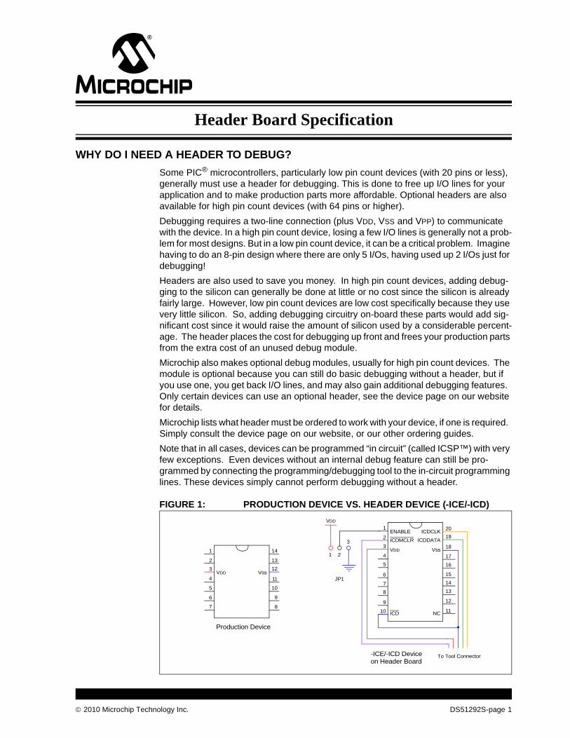
Some PIC® microcontrollers, particularly low pin count devices (with 20 pins or less), generally must use a header for debugging. This is done to free up I/O lines for your application and to make production parts more affordable. Optional headers are also available for high pin count devices (with 64 pins or higher).
Debugging requires a two-line connection (plus VDD, VSS and VPP) to communicate with the device. In a high pin count device, losing a few I/O lines is generally not a prob-lem for most designs. But in a low pin count device, it can be a critical problem. Imagine having to do an 8-pin design where there are only 5 I/Os, having used up 2 I/Os just for debugging!
Headers are also used to save you money. In high pin count devices, adding debug-ging to the silicon can generally be done at little or no cost since the silicon is already fairly large. However, low pin count devices are low cost specifically because they use very little silicon. So, adding debugging circuitry on-board these parts would add sig-nificant cost since it would raise the amount of silicon used by a considerable percent-age. The header places the cost for debugging up front and frees your production parts from the extra cost of an unused debug module.
Microchip also makes optional debug modules, usually for high pin count devices. The module is optional because you can still do basic debugging without a header, but if you use one, you get back I/O lines, and may also gain additional debugging features. Only certain devices can use an optional header, see the device page on our website for details.
Microchip lists what header must be ordered to work with your device, if one is required. Simply consult the device page on our website, or our other ordering guides.
Note that in all cases, devices can be programmed “in circuit” (called ICSP™) with very few exceptions. Even devices without an internal debug feature can still be pro-grammed by connecting the programming/debugging tool to the in-circuit programming lines. These devices simply cannot perform debugging without a header.
FIGURE 1: PRODUCTION DEVICE VS. HEADER DEVICE (-ICE/-ICD)
ENABLE
ICDMCLR
VDD
ICDCLK
ICDDATA
Vss
ICD NC
1
2
3
4
5
6
7
20
19
18
17
16
15
14JP1
21
3
VDD
To Tool Connector
8
9
10 11
12
13
-ICE/-ICD Device
VDD Vss
1
2
3
4
5
6
7
14
13
12
11
10
9
8
on Header Board
Production Device
2010 Microchip Technology Inc. DS51292S-page 1
Header Board Specification
DEBUG DETAILS
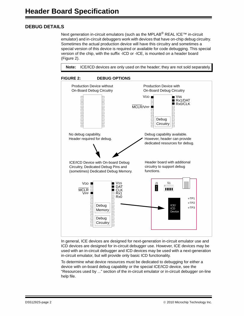
Next generation in-circuit emulators (such as the MPLAB® REAL ICE™ in-circuit emulator) and in-circuit debuggers work with devices that have on-chip debug circuitry. Sometimes the actual production device will have this circuitry and sometimes a special version of this device is required or available for code debugging. This special version of the chip, with the suffix -ICD or -ICE, is mounted on a header board (Figure 2).
FIGURE 2: DEBUG OPTIONS
In general, ICE devices are designed for next-generation in-circuit emulator use and ICD devices are designed for in-circuit debugger use. However, ICE devices may be used with an in-circuit debugger and ICD devices may be used with a next-generation in-circuit emulator, but will provide only basic ICD functionality.
To determine what device resources must be dedicated to debugging for either a device with on-board debug capability or the special ICE/ICD device, see the “Resources used by ...” section of the in-circuit emulator or in-circuit debugger on-line help file.
Note: ICE/ICD devices are only used on the header; they are not sold separately.
Production Device withoutOn-Board Debug Circuitry
DebugCircuitry
Production Device withOn-Board Debug Circuitry
VDD
MCLR/VPP
Vss
Rx0/CLKRx1/DAT
DebugCircuitry
No debug capability.Header required for debug.
Debug capability available.However, header can provide dedicated resources for debug.
VDD
VPP
VSS
CLKDAT
Rx0Rx1
DebugMemory
MCLR
ICE/ICD Device with On-board Debug Circuitry, Dedicated Debug Pins and (sometimes) Dedicated Debug Memory.
Header board with additional circuitry to support debug functions.
J1 S1
ON
TP1
TP2
TP3ICE/ICDDevice
DS51292S-page 2 2010 Microchip Technology Inc.

Header Board Specification
PROGRAMMING DETAILS
The header board is designed to be used with the in-circuit emulator or the in-circuit debugger selected as a debugger, not a programmer, in MPLAB IDE. Any program-ming of the ICE/ICD device on the header is for debug purposes and includes the debug executive. See your related debug tool documentation for details on using it as a debugger.
To program production (non-ICE/ICD) devices with your debug tool, use the Universal Programming Module (AC162049) or design a modular interface connector on the target. See the appropriate specification for connections. For the most up-to-date device programming specifications, see the Microchip website (www.microchip.com).
Also, production devices may be programmed with the following tools:
• MPLAB PM3 device programmer
• PICSTART® Plus development programmer
• PICkit™ 1, 2 or 3 development programmer
• MPLAB ICD 3 in-circuit debugger (select as a programmer)
• MPLAB REAL ICE in-circuit emulator (select as a programmer)
GENERAL HEADER SETUP
To set up your header, do the following:
1. Check the header board for any stickers and the header box for any paper inserts that may specify special operating instructions (Figure 3). Follow these instructions before doing anything else.
FIGURE 3: SPECIAL HEADER INSTRUCTIONS
2. Set any jumpers or switches on the header to determine device functionality or selection as specified for that header. See the sections “Optional Headers” or “Required Headers” for information on how to set up individual headers.
Header Board (Top)
CAUTIONCAUTION
2010 Microchip Technology Inc. DS51292S-page 3
Header Board Specification
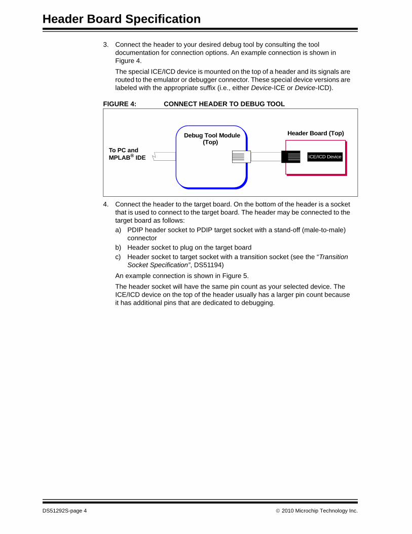
3. Connect the header to your desired debug tool by consulting the tool documentation for connection options. An example connection is shown in Figure 4.
The special ICE/ICD device is mounted on the top of a header and its signals are routed to the emulator or debugger connector. These special device versions are labeled with the appropriate suffix (i.e., either Device-ICE or Device-ICD).
FIGURE 4: CONNECT HEADER TO DEBUG TOOL
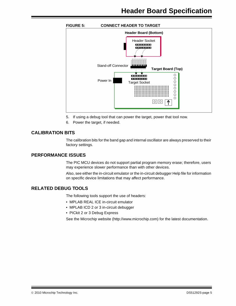
4. Connect the header to the target board. On the bottom of the header is a socket that is used to connect to the target board. The header may be connected to the target board as follows:
a) PDIP header socket to PDIP target socket with a stand-off (male-to-male) connector
b) Header socket to plug on the target board
c) Header socket to target socket with a transition socket (see the “Transition Socket Specification”, DS51194)
An example connection is shown in Figure 5.
The header socket will have the same pin count as your selected device. The ICE/ICD device on the top of the header usually has a larger pin count because it has additional pins that are dedicated to debugging.
Header Board (Top)
ICE/ICD Device
Debug Tool Module(Top)
To PC and MPLAB® IDE
DS51292S-page 4 2010 Microchip Technology Inc.
Header Board Specification
FIGURE 5: CONNECT HEADER TO TARGET
5. If using a debug tool that can power the target, power that tool now.
6. Power the target, if needed.
CALIBRATION BITS
The calibration bits for the band gap and internal oscillator are always preserved to their factory settings.
PERFORMANCE ISSUES
The PIC MCU devices do not support partial program memory erase; therefore, users may experience slower performance than with other devices.
Also, see either the in-circuit emulator or the in-circuit debugger Help file for information on specific device limitations that may affect performance.
RELATED DEBUG TOOLS
The following tools support the use of headers:
• MPLAB REAL ICE in-circuit emulator
• MPLAB ICD 2 or 3 in-circuit debugger
• PICkit 2 or 3 Debug Express
See the Microchip website (http://www.microchip.com) for the latest documentation.
Power In
Target Board (Top)
Target Socket
Stand-off Connector
Header Board (Bottom)
Header Socket
2010 Microchip Technology Inc. DS51292S-page 5

Header Board Specification
CUSTOMER SUPPORT
Users of Microchip products can receive assistance through several channels:
• Distributor or Representative
• Local Sales Office
• Field Application Engineer (FAE)
• Technical Support
Customers should contact their distributor, representative or field application engineer (FAE) for support. Local sales offices are also available to help customers.
Technical support is available through the web site at: http://support.microchip.com.
Documentation errors or comments may be emailed to [email protected].
DS51292S-page 6 2010 Microchip Technology Inc.

Required Headers
Some devices have no built-in debug circuitry. Therefore, special ICE/ICD versions of these devices are required for debug tool operation.
Currently available headers and their associated ICE/ICD devices are shown below by supported device.
TABLE 1: REQUIRED HEADERS BY DEVICE
DevicePin
CountHeader Part
NumberICE/ICD Device Used VDD Max
PIC10F200/2/4/6 8/14 AC162059 PIC16F505-ICD 5.5V
PIC10F220/2 8/14 AC162070 PIC16F506-ICD 5.5V
PIC12F508/509 8/14 AC162059 PIC16F505-ICD 5.5V
PIC12F510 8/14 AC162070 PIC16F506-ICD 5.5V
PIC12F519 8/14 AC162096 PIC16F526-ICD 5.5V
PIC12F609/HV609 28 AC162083 PIC16F616-ICD 5.5V
PIC12F615/HV615 28 AC162083 PIC16F616-ICD 5.5V
PIC12F617 28 AC162083 PIC16F616-ICD 5.5V
PIC12F629 8 AC162050 PIC12F675-ICD 5.5V
PIC12F635 14 AC162057 PIC16F636-ICD 5.5V
PIC12F675 8 AC162050 PIC12F675-ICD 5.5V
PIC12F683 8 AC162058 PIC12F683-ICD 5.5V
PIC16F505 8/14 AC162059 PIC16F505-ICD 5.5V
PIC16F506 8/14 AC162070 PIC16F506-ICD 5.5V
PIC16F526 8/14 AC162096 PIC16F526-ICD 5.5V
PIC16F610/HV610 14/16 AC162083 PIC16F616-ICD 5.5V
PIC16F616/HV616 14/16 AC162083 PIC16F616-ICD 5.5V
PIC16F627A/628A 18 AC162053 PIC16F648A-ICD 5.5V
PIC16F630 14 AC162052 PIC16F676-ICD 5.5V
PIC16F631 20 AC162061 PIC16F690-ICD 5.5V
PIC16F636 14 AC162057 PIC16F636-ICD 5.5V
PIC16F639(1) 20 AC162066 PIC16F636-ICD 5.5V
PIC16F648A 18 AC162053 PIC16F648A-ICD 5.5V
PIC16F676 14 AC162052 PIC16F676-ICD 5.5V
PIC16F677 20 AC162061 PIC16F690-ICD 5.5V
PIC16F684 14 AC162055 PIC16F684-ICD 5.5V
PIC16F685/687 20 AC162061 PIC16F690-ICD 5.5V
PIC16F688 14 AC162056 PIC16F688-ICD 5.5V
PIC16F689/690 20 AC162061 PIC16F690-ICD 5.5V
2010 Microchip Technology Inc. DS51292S-page 7
Required Headers
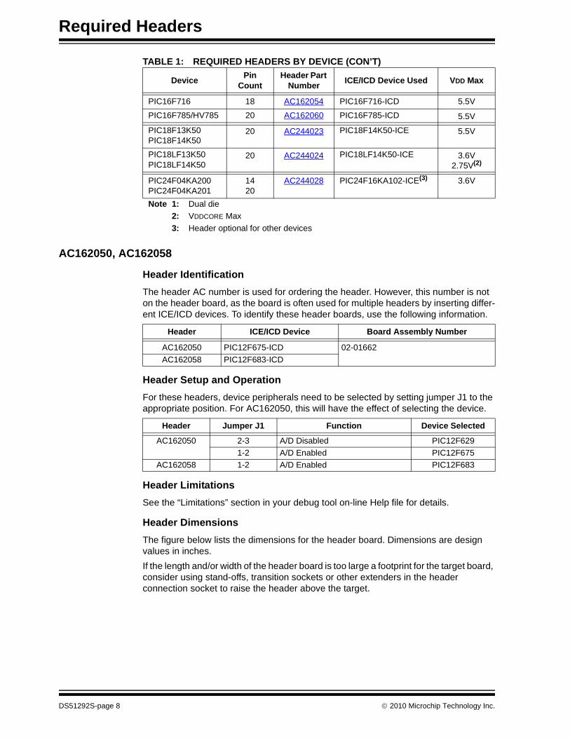
AC162050, AC162058
Header Identification
The header AC number is used for ordering the header. However, this number is not on the header board, as the board is often used for multiple headers by inserting differ-ent ICE/ICD devices. To identify these header boards, use the following information.
Header Setup and Operation
For these headers, device peripherals need to be selected by setting jumper J1 to the appropriate position. For AC162050, this will have the effect of selecting the device.
Header Limitations
See the “Limitations” section in your debug tool on-line Help file for details.
Header Dimensions
The figure below lists the dimensions for the header board. Dimensions are design values in inches.
If the length and/or width of the header board is too large a footprint for the target board, consider using stand-offs, transition sockets or other extenders in the header connection socket to raise the header above the target.
PIC16F716 18 AC162054 PIC16F716-ICD 5.5V
PIC16F785/HV785 20 AC162060 PIC16F785-ICD 5.5V
PIC18F13K50PIC18F14K50
20 AC244023 PIC18F14K50-ICE 5.5V
PIC18LF13K50PIC18LF14K50
20 AC244024 PIC18LF14K50-ICE 3.6V2.75V(2)
PIC24F04KA200PIC24F04KA201
1420
AC244028 PIC24F16KA102-ICE(3) 3.6V
Note 1: Dual die
2: VDDCORE Max
3: Header optional for other devices
TABLE 1: REQUIRED HEADERS BY DEVICE (CON’T)
DevicePin
CountHeader Part
NumberICE/ICD Device Used VDD Max
Header ICE/ICD Device Board Assembly Number
AC162050 PIC12F675-ICD 02-01662
AC162058 PIC12F683-ICD
Header Jumper J1 Function Device Selected
AC162050 2-3 A/D Disabled PIC12F629
1-2 A/D Enabled PIC12F675
AC162058 1-2 A/D Enabled PIC12F683
DS51292S-page 8 2010 Microchip Technology Inc.

Required Headers
FIGURE 1: DIMENSIONS – AC162050, AC162058
Side
0.165 Typical
0.062 Typical
Dimensions are in inches
1.275
0.700
1.000
0.525
6 ConductorModular Cable
Target Pin 1 Located onBottom side of Header
Top
0.560Typical
J1
J2
P1
1
2010 Microchip Technology Inc. DS51292S-page 9

Required Headers
AC162052, AC162055, AC162056, AC162057
Header Identification
The header AC number is used for ordering the header. However, this number is not on the header board, as the board is often used for multiple headers by inserting different ICE/ICD devices. To identify these header boards, use the following information.
Header Setup and Operation
For these headers, device peripherals need to be selected by setting jumper J1 to the appropriate position. For AC162052 and AC162057, this will have the effect of selecting the device.
Header Limitations
See the “Limitations” section in your debug tool on-line Help file for details.
Header ICE/ICD Device Board Assembly Number
AC162052 PIC16F676-ICD 02-01686
AC162055 PIC16F684-ICD
AC162056 PIC16F688-ICD
AC162057 PIC16F636-ICD
Header Jumper J1 Function Device Selected
AC162052 2-3 A/D Disabled PIC16F630
1-2 A/D Enabled PIC16F676
AC162055 Don’t care N/A PIC16F684
AC162056 Don’t care N/A PIC16F688
AC162057 2-3 PORTC, Comparator 2 Disabled PIC12F635
1-2 PORTC, Comparator 2 Enabled PIC16F636
DS51292S-page 10 2010 Microchip Technology Inc.
Required Headers
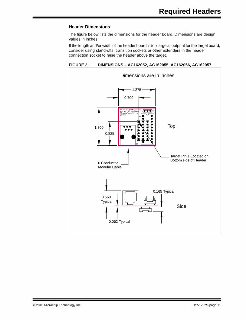
Header Dimensions
The figure below lists the dimensions for the header board. Dimensions are design values in inches.
If the length and/or width of the header board is too large a footprint for the target board, consider using stand-offs, transition sockets or other extenders in the header connection socket to raise the header above the target.
FIGURE 2: DIMENSIONS – AC162052, AC162055, AC162056, AC162057
Dimensions are in inches
1.275
0.700
1.300
0.825
6 ConductorModular Cable
Target Pin 1 Located onBottom side of Header
Top
Side
0.165 Typical
0.062 Typical
0.560Typical
J1
J2
P1
1
2010 Microchip Technology Inc. DS51292S-page 11
Required Headers
AC162053, AC162054
Header Identification
The header AC number is used for ordering the header. However, this number is not on the header board, as the board is often used for multiple headers by inserting different ICE/ICD devices. To identify these header boards, use the following information.
Header Setup and Operation – AC162053
For this headers, there are no jumpers/switches. The device with the most program memory is always selected.
If PIC16F627A or PIC16F628A devices are selected for development in MPLAB IDE, the warning “Invalid target device ID” may be received in the build window and as a dia-log. The reason is the PIC16F648A-ICD device supports PIC16F648A, PIC16F627A and PIC16F628A, but only reports the device ID for the PIC16F648A.
Ignore this warning or disable it under the Warnings tab on the ICD Programming dialog.
Header Setup and Operation – AC162054
This header supports one device (PIC16F716) so there are no jumpers or switches.
Header Limitations
See the “Limitations” section in your debug tool on-line Help file for details.
Header ICE/ICD Device Board Assembly Number
AC162053 PIC16F648A-ICD 02-01695
AC162054 PIC16F716-ICD
DS51292S-page 12 2010 Microchip Technology Inc.
Required Headers
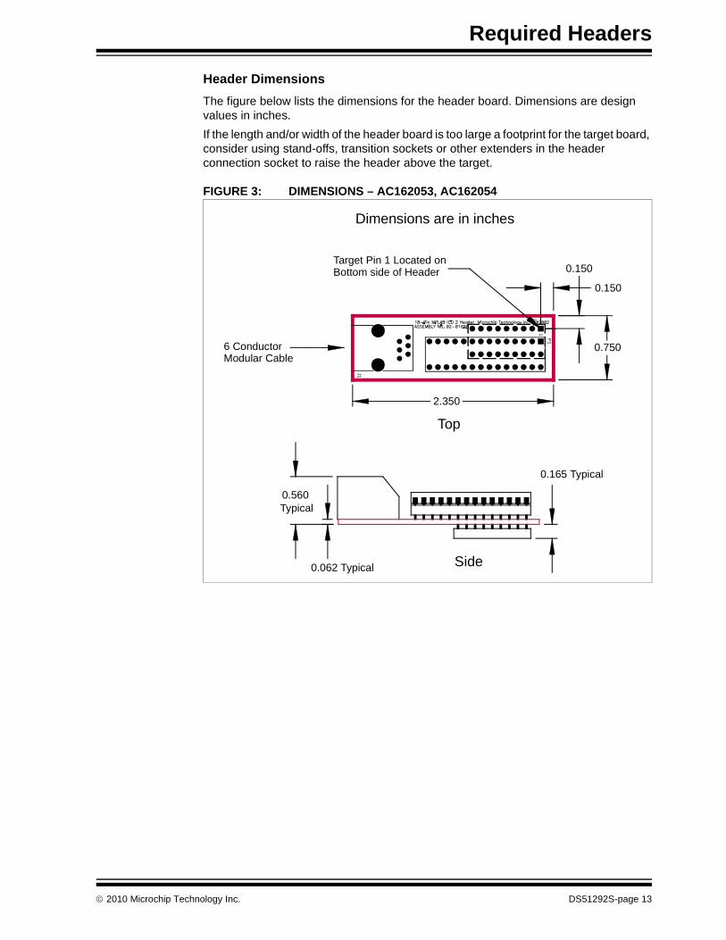
Header Dimensions
The figure below lists the dimensions for the header board. Dimensions are design values in inches.
If the length and/or width of the header board is too large a footprint for the target board, consider using stand-offs, transition sockets or other extenders in the header connection socket to raise the header above the target.
FIGURE 3: DIMENSIONS – AC162053, AC162054
6 ConductorModular Cable
Target Pin 1 Located onBottom side of Header
Dimensions are in inches
2.350
Top
0.150
0.150
0.750
J1
P1
1
Side
0.165 Typical
0.062 Typical
0.560Typical
2010 Microchip Technology Inc. DS51292S-page 13

Required Headers
AC162059, AC162070, AC162096
Header Identification
The header AC number is used for ordering the header. However, this number is not on the header board, as the board is often used for multiple headers by inserting different ICE/ICD devices. To identify these header boards, use the following information.
Header Setup and Operation
The ICD devices on these headers are specifically designed to select a device without the use of additional jumpers or switches.
These headers support 8 and 14-pin devices (see Figure 4.) For the AC162059 and AC162070, there is an 8-pin and a 14-pin connector. For the AC162096, there is only a 14-pin connector. (The 8-pin connector is not populated.) Use the 14-pin connector for 8-pin devices, but make sure device pin 1 is placed at the 14-pin connector pin 1.
Header Limitations
See the “Limitations” section in your debug tool on-line Help file for details.
Header ICE/ICD Device Board Assembly Number
AC162059 PIC16F505-ICD 02-01803
AC162070 PIC16F506-ICD
AC162096 PIC16F526-ICD
DS51292S-page 14 2010 Microchip Technology Inc.
Required Headers
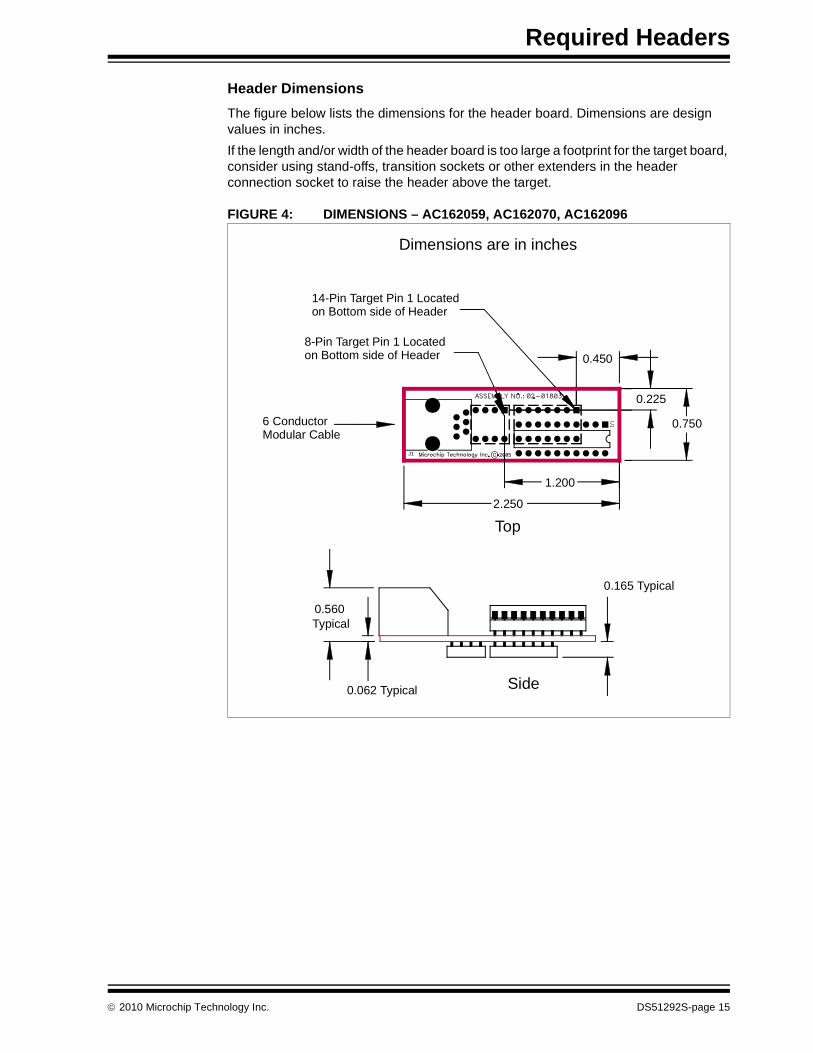
Header Dimensions
The figure below lists the dimensions for the header board. Dimensions are design values in inches.
If the length and/or width of the header board is too large a footprint for the target board, consider using stand-offs, transition sockets or other extenders in the header connection socket to raise the header above the target.
FIGURE 4: DIMENSIONS – AC162059, AC162070, AC162096
Side
0.165 Typical
0.062 Typical
0.560Typical
6 ConductorModular Cable
14-Pin Target Pin 1 Locatedon Bottom side of Header
2.250
0.450
0.225
0.750
1.200
8-Pin Target Pin 1 Locatedon Bottom side of Header
Dimensions are in inches
Top
J1
U1
2010 Microchip Technology Inc. DS51292S-page 15
Required Headers
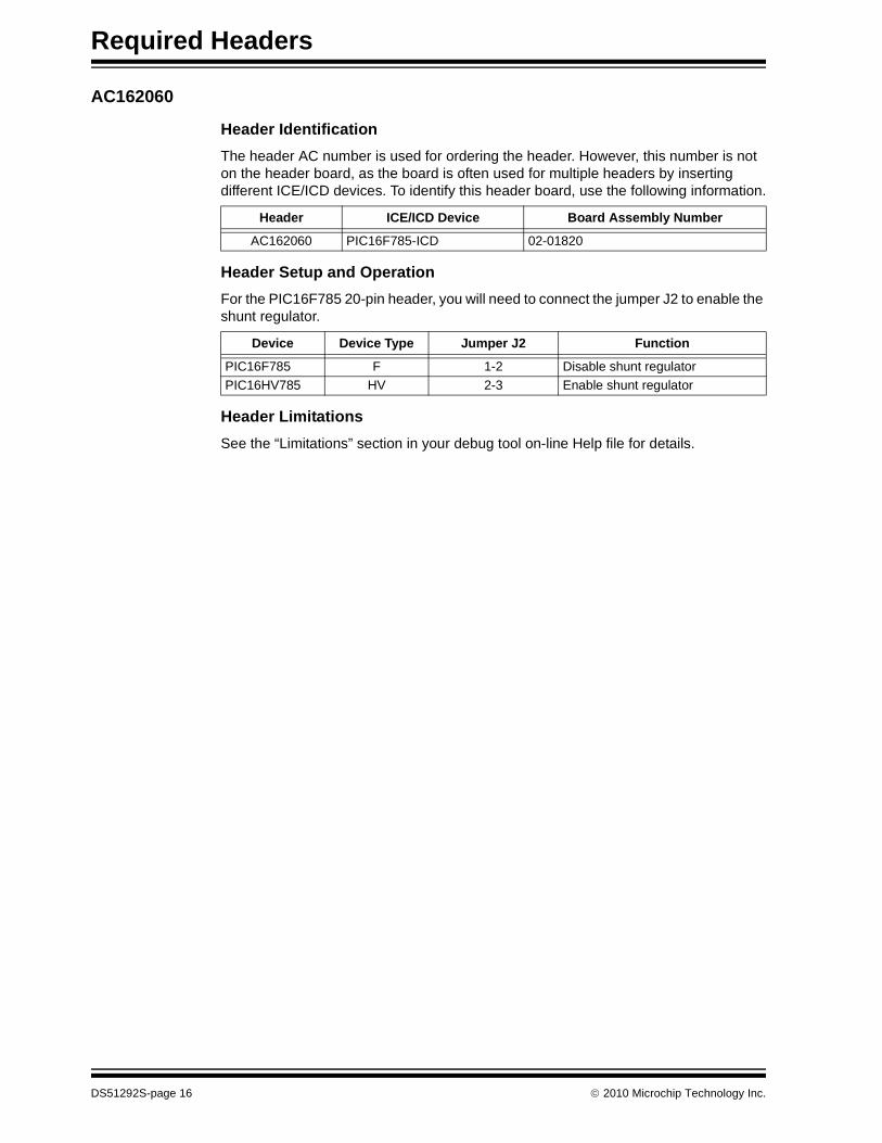
AC162060
Header Identification
The header AC number is used for ordering the header. However, this number is not on the header board, as the board is often used for multiple headers by inserting different ICE/ICD devices. To identify this header board, use the following information.
Header Setup and Operation
For the PIC16F785 20-pin header, you will need to connect the jumper J2 to enable the shunt regulator.
Header Limitations
See the “Limitations” section in your debug tool on-line Help file for details.
Header ICE/ICD Device Board Assembly Number
AC162060 PIC16F785-ICD 02-01820
Device Device Type Jumper J2 Function
PIC16F785 F 1-2 Disable shunt regulator
PIC16HV785 HV 2-3 Enable shunt regulator
DS51292S-page 16 2010 Microchip Technology Inc.
Required Headers
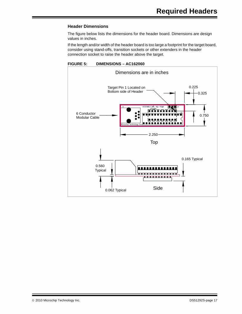
Header Dimensions
The figure below lists the dimensions for the header board. Dimensions are design values in inches.
If the length and/or width of the header board is too large a footprint for the target board, consider using stand-offs, transition sockets or other extenders in the header connection socket to raise the header above the target.
FIGURE 5: DIMENSIONS – AC162060
6 ConductorModular Cable
Target Pin 1 Located onBottom side of Header
Dimensions are in inches
2.250
Top
0.225
0.325
0.750
Side
0.165 Typical
0.062 Typical
0.560Typical
J1 J2
U1
2010 Microchip Technology Inc. DS51292S-page 17
Required Headers
AC162061
Header Identification
The header AC number is used for ordering the header. However, this number is not on the header board, as the board is often used for multiple headers by inserting different ICE/ICD devices. To identify this header board, use the following information.
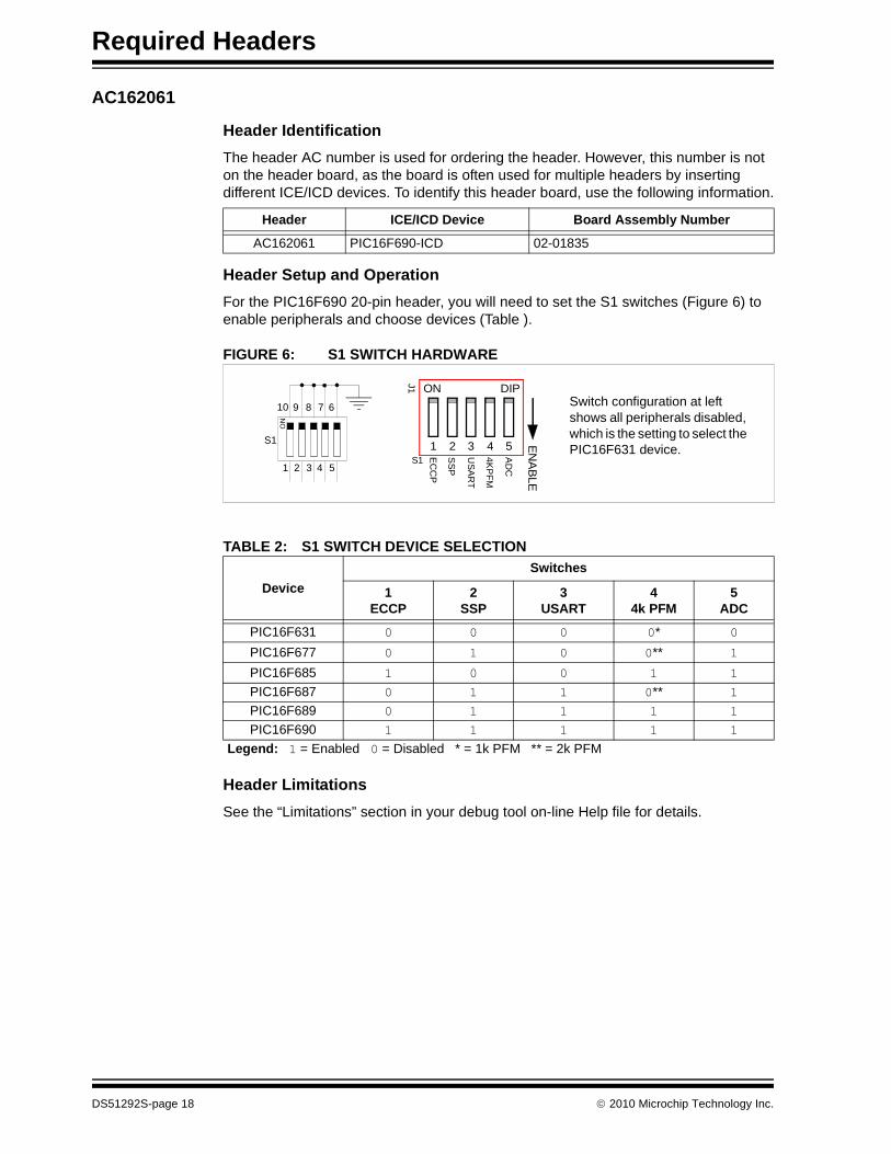
Header Setup and Operation
For the PIC16F690 20-pin header, you will need to set the S1 switches (Figure 6) to enable peripherals and choose devices (Table ).
FIGURE 6: S1 SWITCH HARDWARE
Header Limitations
See the “Limitations” section in your debug tool on-line Help file for details.
Header ICE/ICD Device Board Assembly Number
AC162061 PIC16F690-ICD 02-01835
TABLE 2: S1 SWITCH DEVICE SELECTION
Device
Switches
1ECCP
2SSP
3USART
44k PFM
5ADC
PIC16F631 0 0 0 0* 0PIC16F677 0 1 0 0** 1PIC16F685 1 0 0 1 1PIC16F687 0 1 1 0** 1PIC16F689 0 1 1 1 1PIC16F690 1 1 1 1 1
Legend: 1 = Enabled 0 = Disabled * = 1k PFM ** = 2k PFM
Switch configuration at left shows all peripherals disabled, which is the setting to select the PIC16F631 device.
ON DIP
1 2 3 4 5 EN
AB
LE
AD
C
4K
PF
M
US
AR
T
SS
P
EC
CP
J1
S1
S1
ON
1 2 3 4 5
678910
DS51292S-page 18 2010 Microchip Technology Inc.
Required Headers
Header Dimensions
The figure below lists the dimensions for the header board. Dimensions are design values in inches.
If the length and/or width of the header board is too large a footprint for the target board, consider using stand-offs, transition sockets or other extenders in the header connection socket to raise the header above the target.
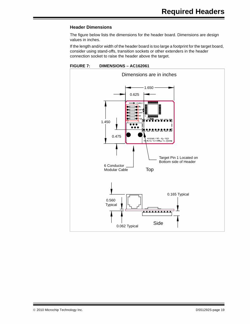
FIGURE 7: DIMENSIONS – AC162061
Side
0.165 Typical
0.062 Typical
0.560Typical
6 ConductorModular Cable
Target Pin 1 Located onBottom side of Header
Dimensions are in inches
Top
1.650
0.625
1.450
0.475
2010 Microchip Technology Inc. DS51292S-page 19

Required Headers
AC162066
Header Identification
The header AC number is used for ordering the header. However, this number is not on the header board, as the board is often used for multiple headers by inserting different ICE/ICD devices. To identify this header board, use the following information.
Header Setup and Operation
For the PIC16F639 20-pin header, you will need to connect the jumper J3 as specified below.
In addition to being used with debug tools that normally use headers, this header is used with the PCM16YM0 processor module to emulate a PIC16F639 on the MPLAB ICE 2000 in-circuit emulator. Plug the end of the processor module into the header, and then plug the header into the transition socket or directly onto the target board.
Header Limitations
See the “Limitations” section in your debug tool on-line Help file for details.
Header ICE/ICD Device Board Assembly Number
AC162066 PIC16F636-ICD 02-01832
Tool Jumper J3 Function
MPLAB® ICE 2000 1-2 Run/program as production device
In-circuit debuggers,next generation in-circuit emulators
2-3 Run/program as ICD device
DS51292S-page 20 2010 Microchip Technology Inc.
Required Headers
Header Dimensions
The figure below lists the dimensions for the header board. Dimensions are design values in inches.
If the length and/or width of the header board is too large a footprint for the target board, consider using stand-offs, transition sockets or other extenders in the header connection socket to raise the header above the target.
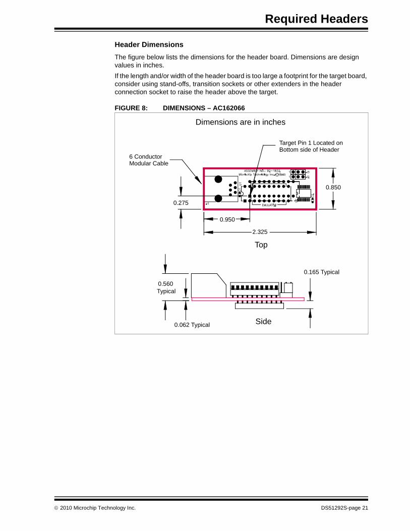
FIGURE 8: DIMENSIONS – AC162066
6 ConductorModular Cable
Target Pin 1 Located onBottom side of Header
Dimensions are in inches
2.325
Top
0.275
0.950
0.850
Side
0.165 Typical
0.062 Typical
0.560Typical
2010 Microchip Technology Inc. DS51292S-page 21

Required Headers
AC162083
Header Identification
The header AC number is used for ordering the header. However, this number is not on the header board, as the board is often used for multiple headers by inserting different ICE/ICD devices. To identify this header board, use the following information.
Header Setup and Operation
Test points are available on this header to check the following: Ground (TP1), VDD (TP2), ICD Clock (TP3), ICD Data (TP4) and ICD MCLR/VPP (TP5).
POTENTIAL ISSUES
HV device selected instead of F device
If you inadvertently select a shunt regulator (HV) device and attempt to use it in a target board designed for a non-shunt regulator (F) device, the shunt may draw excessive current due to the lack of current-limiting circuitry on the target board and damage the device mounted on the header.
F device selected instead of HV device
If you inadvertently select a non-shunt regulator (F) device and attempt to use it in a target board designed for a shunt regulator (HV) device, the device may draw exces-sive current due to the higher voltage used on a target board designed for HV devices and damage the device mounted on the header.
HV devices cannot be powered from debug tool
Do not select in MPLAB IDE to power the target (debug header) from the debug tool (if it supports powering the target) when using shunt regulator (HV) devices since this will also cause the shunt to draw excessive current.
Header ICE/ICD Device Board Assembly Number
AC162083 PIC16F616-ICD 02-01976
CAUTION
Incorrect rotary switch (Figure 9) settings may irreparably damage the header. Ensure rotary switch settings are correct (Table 3) before powering or connecting the header. Do not change the rotary switch setting while the header is powered or connected to a debug tool. Do not power shunt regulator (HV) devices from the debug tool.
TABLE 3: ROTARY SWITCH SETTINGS
Switch Position Device Switch Position Device
0 PIC12HV609 8 PIC12F609
1 PIC12HV615 9 PIC12F615
2 Reserved HV A PIC12F617
3 PIC16HV610 B PIC16F610
4 PIC16HV616 C PIC16F616
5 Reserved HV D Reserved F
6 Reserved HV E Reserved F
7 Reserved HV F Reserved F
DS51292S-page 22 2010 Microchip Technology Inc.

Required Headers
DETERMINING DAMAGE
A damaged header will cause MPLAB IDE to report a device ID of 0. However, there are other issues that can cause the device ID to report as 0. Please consult your debug tool documentation on troubleshooting to identify the problem. If you believe you have a damaged header, please contact Microchip technical support at http://support.microchip.com.
Header Limitations
See the “Limitations” section in your debug tool on-line Help file for details.
Header Dimensions
The figure below lists the dimensions for the header board. Dimensions are design values in inches.
If the length and/or width of the header board is too large a footprint for the target board, consider using stand-offs, transition sockets or other extenders in the header connection socket to raise the header above the target.
FIGURE 9: DIMENSIONS – AC162083
6 ConductorModular Cable
Target Pin 1 Located onBottom side of Header
Dimensions are in inches
2.450
Top
0.600
0.650
1.600
Side
0.165 Typical
0.062 Typical
0.560Typical
RotarySwitch
Use for Both 14-pin and 8-pin Device Alignment
2010 Microchip Technology Inc. DS51292S-page 23

Required Headers
AC244023, AC244024
Header Identification
The header AC number is used for ordering the header. However, this number is not on the header board, as the board is often used for multiple headers by inserting different ICE/ICD devices. To identify these header boards, use the following information.
Header Setup and Operation
When the MPLAB ICD 2 is used with this header, you must use the Vpp Limiter (AC164112).
FIGURE 10: VPP LIMITER SCHEMATIC
Header Limitations
See the “Limitations” section in your debug tool on-line Help file for details.
Header ICE/ICD Device Board Assembly Number
AC244023 PIC18F14K50-ICE 02-02031
AC244024 PIC18LF14K50-ICE
VREF
J1
VPP
VDD
VSS
ICSP_DATAICSP_CLOCK
NC
RJ11-6PIN
RJ11-6PIN
J2R1
270 Ohm
To MPLAB® ICD To Target Board
123456 1
23456
R2 R3
10k 1% 24k 1%
U1
LM431BCMX
A2367
8
AAA
K
NCNC
1
45
DS51292S-page 24 2010 Microchip Technology Inc.
Required Headers
Header Dimensions
The figure below lists the dimensions for the header board. Dimensions are design values in inches.
If the length and/or width of the header board is too large a footprint for the target board, consider using stand-offs, transition sockets or other extenders in the header connection socket to raise the header above the target.
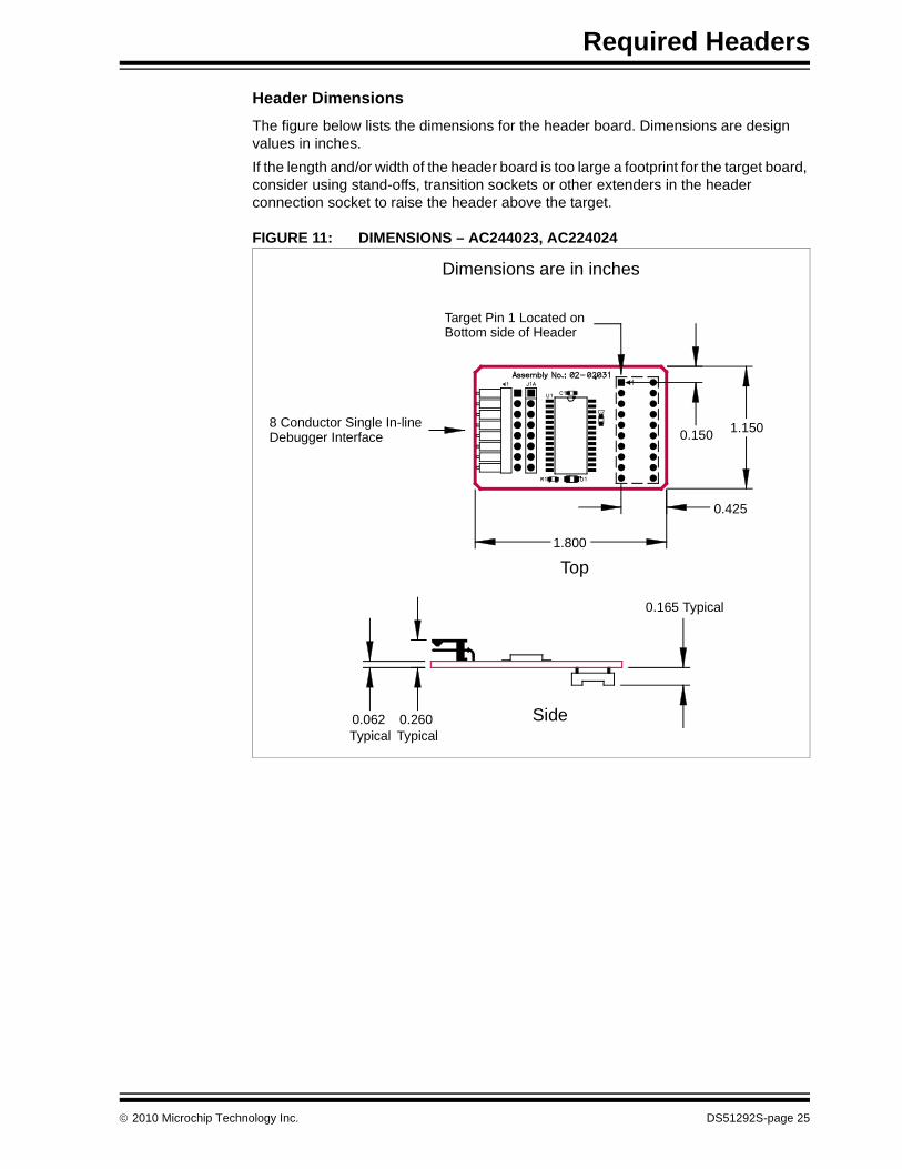
FIGURE 11: DIMENSIONS – AC244023, AC224024
8 Conductor Single In-lineDebugger Interface
Target Pin 1 Located onBottom side of Header
Dimensions are in inches
Top
1.800
0.150 1.150
0.425
Side
0.165 Typical
0.062Typical
0.260Typical
2010 Microchip Technology Inc. DS51292S-page 25

Required Headers
AC244028
Header Identification
The header AC number is used for ordering the header. However, this number is not on the header board, as the board is often used for multiple headers by inserting differ-ent ICE/ICD devices. To identify this header board, use the following information.
Header Setup and Operation
For this header, you will need to set up jumper J2 and J3.
Header Limitations
See the “Limitations” section in your debug tool on-line Help file for details.
Header ICE/ICD Device Board Assembly Number
AC244028 PIC24F16KA102-ICE 02-02107
Jumper Setting Function
J2 Open Disable weak ICE/MCLR pull-up resistor
Short Enable weak ICE/MCLR pull-up resistor
J3 Open Disable power LED indicator
Short Enable power LED indicator
DS51292S-page 26 2010 Microchip Technology Inc.
Required Headers
Header Dimensions
The figure below lists the dimensions for the header board. Dimensions are design values in inches.
If the length and/or width of the header board is too large a footprint for the target board, consider using stand-offs, transition sockets or other extenders in the header connection socket to raise the header above the target.
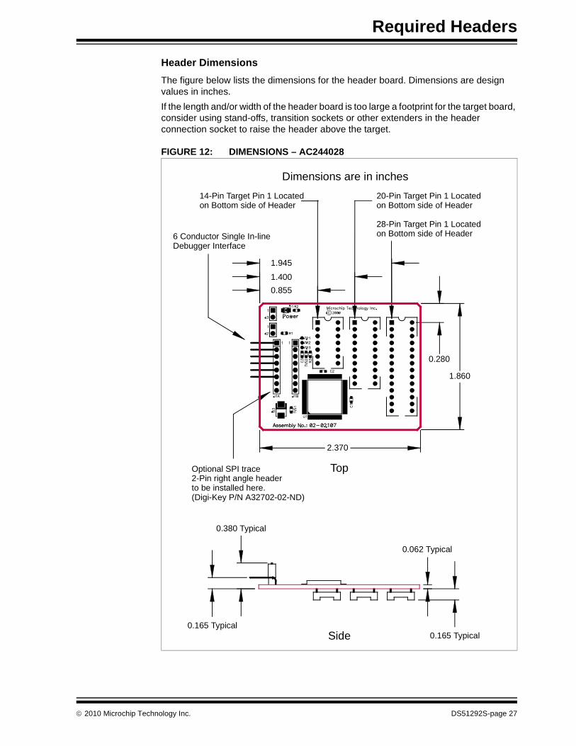
FIGURE 12: DIMENSIONS – AC244028
Dimensions are in inches
Top
Side
0.062 Typical
0.165 Typical0.165 Typical
0.380 Typical
2.370
0.280
1.860
1.945
1.400
0.855
20-Pin Target Pin 1 Locatedon Bottom side of Header
28-Pin Target Pin 1 Locatedon Bottom side of Header
14-Pin Target Pin 1 Locatedon Bottom side of Header
6 Conductor Single In-lineDebugger Interface
Optional SPI trace2-Pin right angle headerto be installed here.(Digi-Key P/N A32702-02-ND)
2010 Microchip Technology Inc. DS51292S-page 27
Required Headers
NOTES:
DS51292S-page 28 2010 Microchip Technology Inc.
Optional Headers
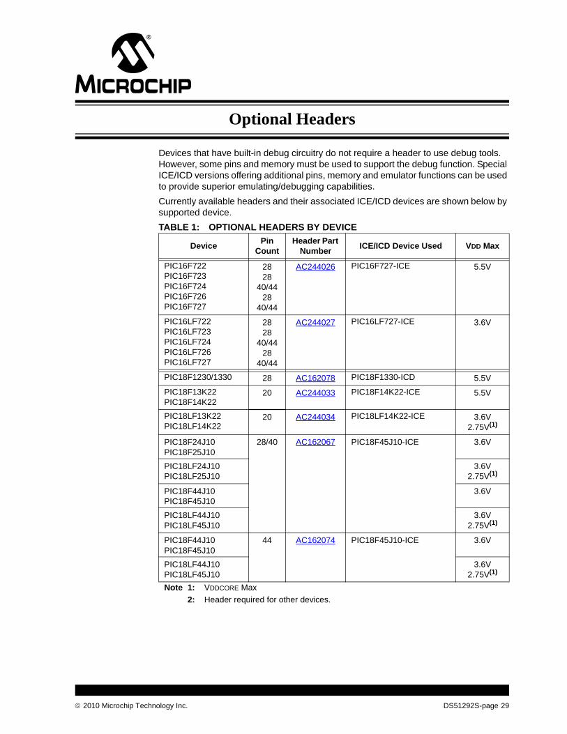
Devices that have built-in debug circuitry do not require a header to use debug tools. However, some pins and memory must be used to support the debug function. Special ICE/ICD versions offering additional pins, memory and emulator functions can be used to provide superior emulating/debugging capabilities.
Currently available headers and their associated ICE/ICD devices are shown below by supported device.
TABLE 1: OPTIONAL HEADERS BY DEVICE
DevicePin
CountHeader Part
NumberICE/ICD Device Used VDD Max
PIC16F722PIC16F723PIC16F724PIC16F726PIC16F727
2828
40/4428
40/44
AC244026 PIC16F727-ICE 5.5V
PIC16LF722PIC16LF723PIC16LF724PIC16LF726PIC16LF727
2828
40/4428
40/44
AC244027 PIC16LF727-ICE 3.6V
PIC18F1230/1330 28 AC162078 PIC18F1330-ICD 5.5V
PIC18F13K22PIC18F14K22
20 AC244033 PIC18F14K22-ICE 5.5V
PIC18LF13K22PIC18LF14K22
20 AC244034 PIC18LF14K22-ICE 3.6V2.75V(1)
PIC18F24J10PIC18F25J10
28/40 AC162067 PIC18F45J10-ICE 3.6V
PIC18LF24J10PIC18LF25J10
3.6V2.75V(1)
PIC18F44J10PIC18F45J10
3.6V
PIC18LF44J10PIC18LF45J10
3.6V2.75V(1)
PIC18F44J10PIC18F45J10
44 AC162074 PIC18F45J10-ICE 3.6V
PIC18LF44J10PIC18LF45J10
3.6V2.75V(1)
Note 1: VDDCORE Max
2: Header required for other devices.
2010 Microchip Technology Inc. DS51292S-page 29

Optional Headers
PIC18F63J11PIC18F63J90PIC18F64J11PIC18F64J16PIC18F64J90PIC18F64J95PIC18F65J11PIC18F65J90
64/80 AC162079 PIC18F85J90-ICE 3.6V
PIC18F83J11PIC18F83J90PIC18F84J11PIC18F84J16PIC18F84J90PIC18F84J95PIC18F85J11PIC18F85J90
PIC18F65J10PIC18F65J15PIC18F66J10PIC18F66J15PIC18F67J10
64/80 AC162062 PIC18F87J10-ICE 3.6V
PIC18F85J10PIC18F85J15PIC18F86J10PIC18F86J15PIC18F87J10
PIC18F65J16PIC18F66J11PIC18F66J16PIC18F67J11
64/80 AC162091 PIC18F87J11-ICE 3.6V
PIC18F85J16PIC18F86J11PIC18F86J16PIC18F87J11
PIC18F65J50PIC18F65J55PIC18F66J50PIC18F66J55PIC18F67J50
64/80 AC162087 PIC18F87J50-ICE 3.6V
PIC18F85J50PIC18F85J55PIC18F86J50PIC18F86J55PIC18F87J50
TABLE 1: OPTIONAL HEADERS BY DEVICE (CON’T)
DevicePin
CountHeader Part
NumberICE/ICD Device Used VDD Max
Note 1: VDDCORE Max
2: Header required for other devices.
DS51292S-page 30 2010 Microchip Technology Inc.

Optional Headers
PIC18F66J60PIC18F66J65PIC18F67J60
64/80/100
AC162064 PIC18F97J60-ICE 3.6V
PIC18F86J60PIC18F86J65PIC18F87J60
PIC18F96J60PIC18F96J65PIC18F97J60
PIC24F08KA101PIC24F08KA102PIC24F16KA101PIC24F16KA102
20/28 AC244028 PIC24F16KA102-ICE(2) 3.6V
PIC24FJ16GA002PIC24FJ32GA002PIC24FJ48GA002PIC24FJ64GA002
28 AC162088 PIC24FJ64GA004-ICE 3.6V
PIC24FJ16GA004PIC24FJ32GA004PIC24FJ48GA004PIC24FJ64GA004
44 AC162094
PIC24FJ64GA006PIC24FJ64GA008PIC24FJ64GA010
64/80/100
AC162065or
AC244022
PIC24FJ128GA010-ICE 3.6V
PIC24FJ96GA006PIC24FJ96GA008PIC24FJ96GA010
PIC24FJ128GA006PIC24FJ128GA008PIC24FJ128GA010
TABLE 1: OPTIONAL HEADERS BY DEVICE (CON’T)
DevicePin
CountHeader Part
NumberICE/ICD Device Used VDD Max
Note 1: VDDCORE Max
2: Header required for other devices.
2010 Microchip Technology Inc. DS51292S-page 31
Optional Headers
AC162062, AC162079, AC162087, AC162091
Header Identification
The header AC number is used for ordering the header. However, this number is not on the header board, as the board is often used for multiple headers by inserting different ICE/ICD devices. To identify these header boards, use the following information.
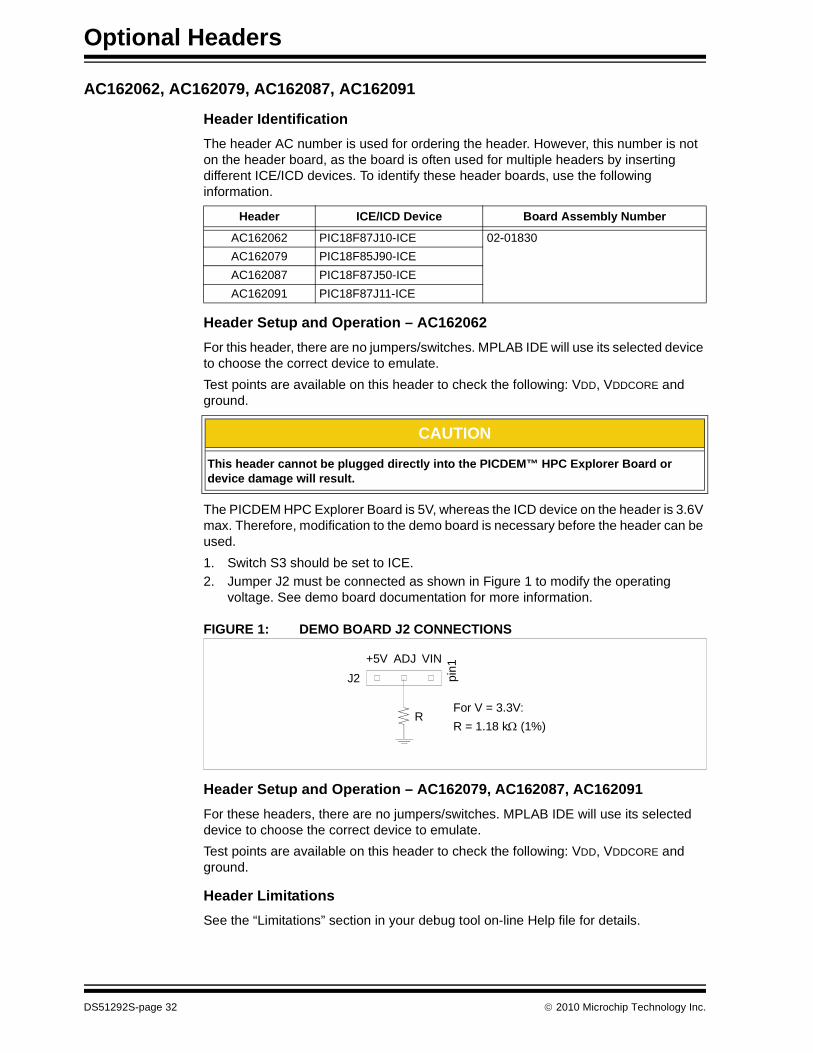
Header Setup and Operation – AC162062
For this header, there are no jumpers/switches. MPLAB IDE will use its selected device to choose the correct device to emulate.
Test points are available on this header to check the following: VDD, VDDCORE and ground.
The PICDEM HPC Explorer Board is 5V, whereas the ICD device on the header is 3.6V max. Therefore, modification to the demo board is necessary before the header can be used.
1. Switch S3 should be set to ICE.
2. Jumper J2 must be connected as shown in Figure 1 to modify the operating voltage. See demo board documentation for more information.
FIGURE 1: DEMO BOARD J2 CONNECTIONS
Header Setup and Operation – AC162079, AC162087, AC162091
For these headers, there are no jumpers/switches. MPLAB IDE will use its selected device to choose the correct device to emulate.
Test points are available on this header to check the following: VDD, VDDCORE and ground.
Header Limitations
See the “Limitations” section in your debug tool on-line Help file for details.
Header ICE/ICD Device Board Assembly Number
AC162062 PIC18F87J10-ICE 02-01830
AC162079 PIC18F85J90-ICE
AC162087 PIC18F87J50-ICE
AC162091 PIC18F87J11-ICE
CAUTION
This header cannot be plugged directly into the PICDEM™ HPC Explorer Board or device damage will result.
J2 pin
1VINADJ+5V
RFor V = 3.3V:
R = 1.18 k (1%)
DS51292S-page 32 2010 Microchip Technology Inc.

Optional Headers
Header Dimensions
The figure below lists the dimensions for the header board. Dimensions are design values in inches.
If the length and/or width of the header board is too large a footprint for the target board, consider using stand-offs, transition sockets or other extenders in the header connection socket to raise the header above the target.
FIGURE 2: DIMENSIONS – AC162062, AC162079, AC162087, AC162091
6 ConductorModular CableTarget Pin 1 Located on
Bottom side of Header
Dimensions are in inches
1.800
Top
0.320
0.420
1.080 0.980
2.325
Side0.062 Typical
0.560Typical
0.335 Typical
0.050
2010 Microchip Technology Inc. DS51292S-page 33
Optional Headers
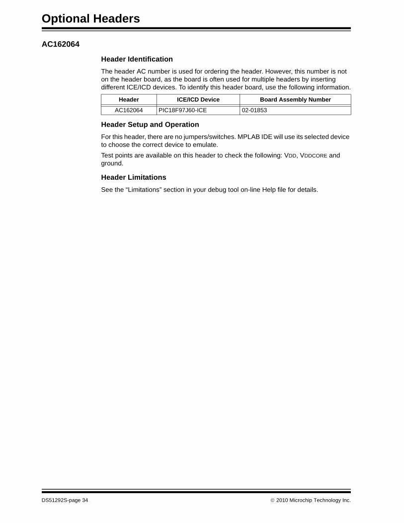
AC162064
Header Identification
The header AC number is used for ordering the header. However, this number is not on the header board, as the board is often used for multiple headers by inserting different ICE/ICD devices. To identify this header board, use the following information.
Header Setup and Operation
For this header, there are no jumpers/switches. MPLAB IDE will use its selected device to choose the correct device to emulate.
Test points are available on this header to check the following: VDD, VDDCORE and ground.
Header Limitations
See the “Limitations” section in your debug tool on-line Help file for details.
Header ICE/ICD Device Board Assembly Number
AC162064 PIC18F97J60-ICE 02-01853
DS51292S-page 34 2010 Microchip Technology Inc.
Optional Headers
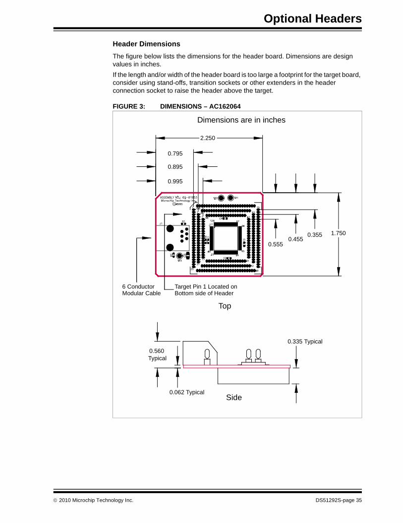
Header Dimensions
The figure below lists the dimensions for the header board. Dimensions are design values in inches.
If the length and/or width of the header board is too large a footprint for the target board, consider using stand-offs, transition sockets or other extenders in the header connection socket to raise the header above the target.
FIGURE 3: DIMENSIONS – AC162064
6 ConductorModular Cable
Target Pin 1 Located onBottom side of Header
Dimensions are in inches
2.250
Top
0.795
0.895
0.995
1.7500.3550.455
0.555
Side0.062 Typical
0.560Typical
0.335 Typical
2010 Microchip Technology Inc. DS51292S-page 35
Optional Headers
AC162065, AC244022
Header Identification
The header AC number is used for ordering the header. However, this number is not on the header board, as the board is often used for multiple headers by inserting different ICE/ICD devices. To identify these header boards, use the following information.
Header Setup and Operation
For this header, there are no jumpers/switches. MPLAB IDE will use its selected device to choose the correct device to emulate.
Test points are available on this header to check the following: VDD, VDDCORE and ground.
Header Limitations
See the “Limitations” section in your debug tool on-line Help file for details.
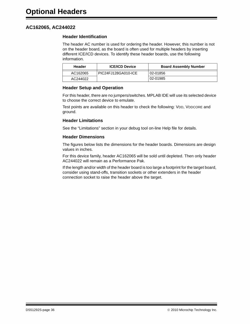
Header Dimensions
The figures below lists the dimensions for the header boards. Dimensions are design values in inches.
For this device family, header AC162065 will be sold until depleted. Then only header AC244022 will remain as a Performance Pak.
If the length and/or width of the header board is too large a footprint for the target board, consider using stand-offs, transition sockets or other extenders in the header connection socket to raise the header above the target.
Header ICE/ICD Device Board Assembly Number
AC162065 PIC24FJ128GA010-ICE 02-01856
AC244022 02-01985
DS51292S-page 36 2010 Microchip Technology Inc.
Optional Headers
FIGURE 4: DIMENSIONS – AC162065
6 ConductorModular Cable
Target Pin 1 Located onBottom side of Header
Dimensions are in inches
2.250
0.795
0.895
0.995
1.7500.3550.455
0.555
Top
Side0.062 Typical
0.560Typical
0.335 Typical
2010 Microchip Technology Inc. DS51292S-page 37

Optional Headers
FIGURE 5: DIMENSIONS – AC244022
Dimensions are in inches
2.200
0.695
0.795
0.895
8 Conductor Single In-lineDebugger Interface
Top
Side0.260Typical
0.335 Typical
0.620Typical
1.8500.325
0.4250.525
Target Pin 1 Located onBottom side of Header
DS51292S-page 38 2010 Microchip Technology Inc.
Optional Headers
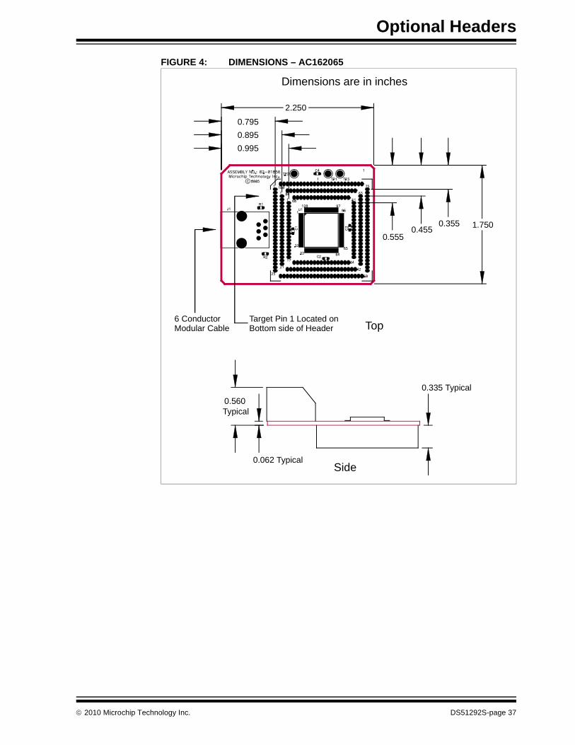
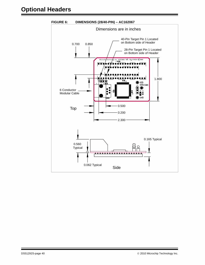
AC162067, AC162074
Header Identification
The header AC number is used for ordering the header. However, this number is not on the header board, as the board is often used for multiple headers by inserting different ICE/ICD devices. To identify these header boards, use the following information.
Header Setup and Operation
For these headers, you will need to connect jumpers J2 and J3 to select between the LF and F versions of devices.
Header Limitations
See the “Limitations” section in your debug tool on-line Help file for details.
Header Dimensions
The figures below lists the dimensions for the header boards. Dimensions are design values in inches.
If the length and/or width of the header board is too large a footprint for the target board, consider using stand-offs, transition sockets or other extenders in the header connection socket to raise the header above the target.
Header ICE/ICD Device Board Assembly Number
AC162067 PIC18F45J10-ICE 02-01854
AC162074 02-01929
Device Device Type Jumper J2 Jumper J3 Function
PIC18LFXXJ10 LF 1-2 1-2 Disable voltage regulator*
PIC18FXXJ10 F 2-3 2-3 Enable voltage regulator
* VDDCORE must be supplied externally.
2010 Microchip Technology Inc. DS51292S-page 39
Optional Headers
FIGURE 6: DIMENSIONS (28/40-PIN) – AC162067
Side0.062 Typical
0.560Typical
0.165 Typical
6 ConductorModular Cable
40-Pin Target Pin 1 Locatedon Bottom side of Header
Dimensions are in inches
Top
28-Pin Target Pin 1 Locatedon Bottom side of Header
0.700 0.850
1.800
0.500
0.200
2.300
DS51292S-page 40 2010 Microchip Technology Inc.

Optional Headers
FIGURE 7: DIMENSIONS (44-PIN) – AC162074
6 ConductorModular Cable
Target Pin 1 Located onBottom side of Header
Dimensions are in inches
Top
Side0.062 Typical
0.560Typical
0.335 Typical
0.850
1.800
1.350
0.925
2010 Microchip Technology Inc. DS51292S-page 41
Optional Headers
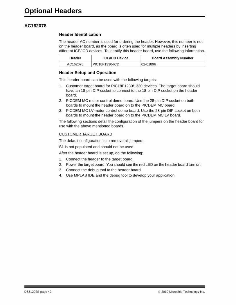
AC162078
Header Identification
The header AC number is used for ordering the header. However, this number is not on the header board, as the board is often used for multiple headers by inserting different ICE/ICD devices. To identify this header board, use the following information.
Header Setup and Operation
This header board can be used with the following targets:
1. Customer target board for PIC18F1230/1330 devices. The target board should have an 18-pin DIP socket to connect to the 18-pin DIP socket on the header board.
2. PICDEM MC motor control demo board. Use the 28-pin DIP socket on both boards to mount the header board on to the PICDEM MC board.
3. PICDEM MC LV motor control demo board. Use the 28-pin DIP socket on both boards to mount the header board on to the PICDEM MC LV board.
The following sections detail the configuration of the jumpers on the header board for use with the above mentioned boards.
CUSTOMER TARGET BOARD
The default configuration is to remove all jumpers.
S1 is not populated and should not be used.
After the header board is set up, do the following:
1. Connect the header to the target board.
2. Power the target board. You should see the red LED on the header board turn on.
3. Connect the debug tool to the header board.
4. Use MPLAB IDE and the debug tool to develop your application.
Header ICE/ICD Device Board Assembly Number
AC162078 PIC18F1330-ICD 02-01896
DS51292S-page 42 2010 Microchip Technology Inc.

Optional Headers
PICDEM MC/MC LV MOTOR CONTROL DEMO BOARDS
To run a BLDC motor on the PICDEM MC board or PICDEM MC LV board using the supplied firmware, use the following jumper setup:
S1 is not populated and should not be used.
After the header board is set up, do the following:
1. Connect the header to the PICDEM MC/MC LV target board.
2. Power the target board. You should see the red LED on the header board turn on.
3. Connect the debug tool to the header board.
4. Program the part with the demo code.
5. Run the program.
6. Press and release switch S2 on the target board to toggle the direction of the motor’s rotation.
7. Press and release switch S1 on the target board to toggle between running and stopping the motor.
8. If the motor stops while reversing from a high speed, there could be an overcurrent condition detected by the system. Reset the system to run the program again.
Header Limitations
See the “Limitations” section in your debug tool on-line Help file for details.
Jumper Jumper Setting Jumper Jumper Setting
J1 2-3JP1 Open
J2 2-3
J3 2-3JP2 Open
J5 2-3
J6 1-2JP3 Open
J7 1-2
2010 Microchip Technology Inc. DS51292S-page 43
Optional Headers
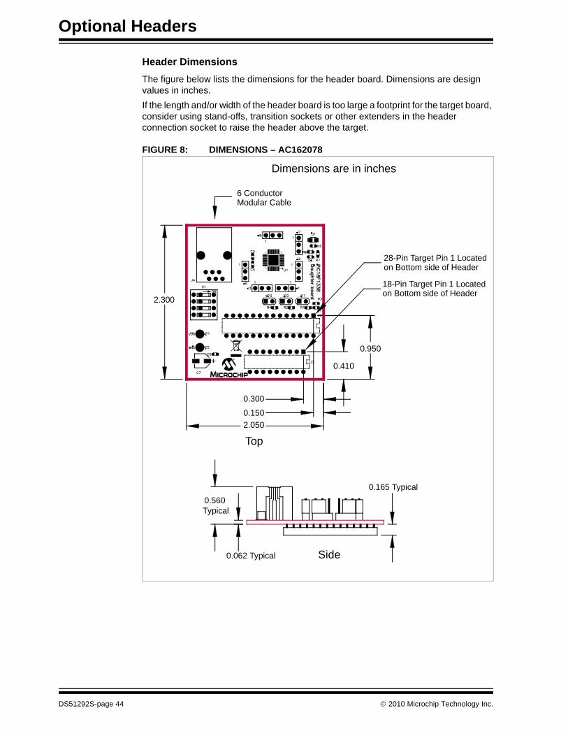
Header Dimensions
The figure below lists the dimensions for the header board. Dimensions are design values in inches.
If the length and/or width of the header board is too large a footprint for the target board, consider using stand-offs, transition sockets or other extenders in the header connection socket to raise the header above the target.
FIGURE 8: DIMENSIONS – AC162078
M
6 ConductorModular Cable
18-Pin Target Pin 1 Locatedon Bottom side of Header
Dimensions are in inches
Top
28-Pin Target Pin 1 Locatedon Bottom side of Header
Side0.062 Typical
0.560Typical
0.165 Typical
2.300
0.950
0.410
0.300
0.150
2.050
DS51292S-page 44 2010 Microchip Technology Inc.
Optional Headers
AC162088, AC162094
Header Identification
The header AC number is used for ordering the header. However, this number is not on the header board, as the board is often used for multiple headers by inserting different ICE/ICD devices. To identify this header board, use the following information.
Header Setup and Operation
Both 28-pin and 44-pin device headers have jumpers related to the enabling or dis-abling of the on-chip 2.5 volt voltage regulator. Please see the section entitled “On-Chip Voltage Regulator” in the “dsPIC33F Family Reference Manual” (DS70165) for more details.
Test points are available on this header to check the following:
Header Limitations
See the “Limitations” section in your debug tool on-line Help file for details.
Header Dimensions
The figures below list the dimensions for the header boards. Dimensions are design values in inches.
If the length and/or width of the header board is too large a footprint for the target board, consider using stand-offs, transition sockets or other extenders in the header connection socket to raise the header above the target.
Header ICE/ICD Device Board Assembly Number
AC162088 PIC24FJ64GA004-ICE 02-01979
AC162094 02-01982
Jumper J2 Function
1-2 Disable voltage regulator
2-3 Enable voltage regulator
No connection DISVREG controlled by target
Test Point Color Signal Test Point Color Signal
TP1 Black Ground TP5 White DISVREG
TP2 Red VDD TP6 White PGC
TP3 Black AVSS TP7 White PGD
TP4 Red AVDD TP8 Yellow ICRST
2010 Microchip Technology Inc. DS51292S-page 45
Optional Headers
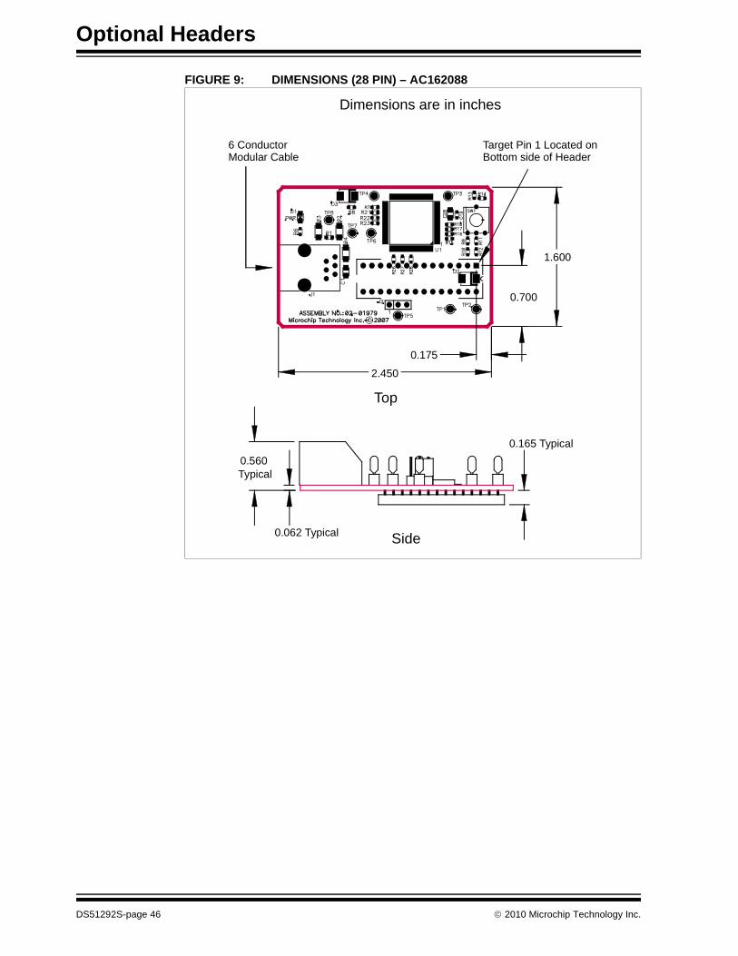
FIGURE 9: DIMENSIONS (28 PIN) – AC162088
6 ConductorModular Cable
Target Pin 1 Located onBottom side of Header
Dimensions are in inches
2.450
Top
0.175
1.600
0.700
Side0.062 Typical
0.560Typical
0.165 Typical
DS51292S-page 46 2010 Microchip Technology Inc.
Optional Headers
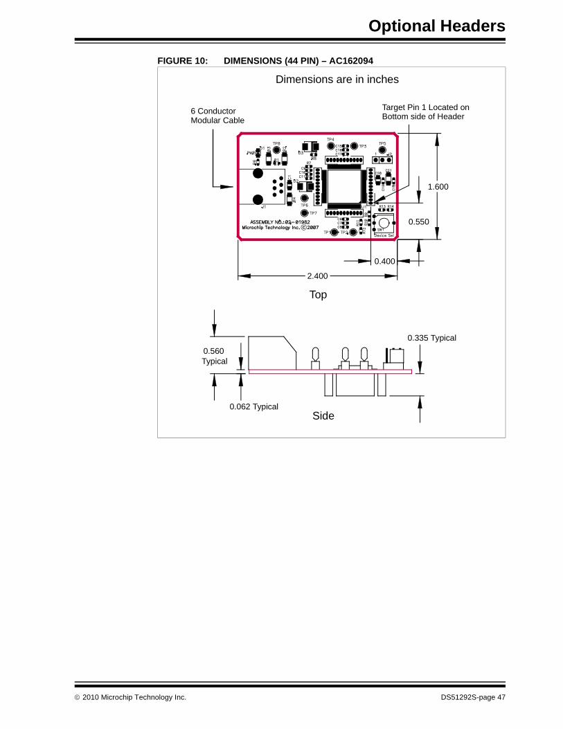
FIGURE 10: DIMENSIONS (44 PIN) – AC162094
6 ConductorModular Cable
Target Pin 1 Located onBottom side of Header
Dimensions are in inches
2.400
Top
0.400
1.600
0.550
Side0.062 Typical
0.560Typical
0.335 Typical
2010 Microchip Technology Inc. DS51292S-page 47
Optional Headers
AC244026, AC244027
Header Identification
The header AC number is used for ordering the header. However, this number is not on the header board, as the board is often used for multiple headers by inserting different ICE/ICD devices. To identify this header board, use the following information.
Header Setup and Operation - AC244026
This Processor Extension Pak provides extra debugging capability not available on PIC16F727 production devices:
• 3 Address / Data breakpoints (1 Address only breakpoint on production devices)
• Data capture (Real Time Data Streaming)
• No user Flash resources needed for debugging
• No user RAM resources needed for debugging
• No user pins required
This header has jumpers available for MCLR pull-up and power LED control.
Additionally, this header has jumpers related to the LDO voltage regulator. Depending on the device pin used for this function, you would use either J4 (RA0), J5 (RA5) or J6 (RA6) for Vcap selection. For details on the voltage regulator, see the “PIC16F72X/PIC16LF72X Data Sheet” (DS41341).
Header ICE/ICD Device Board Assembly Number
AC244026 PIC16F727-ICE 02-02105
AC244027 PIC16LF727-ICE
Jumper Setting Function
J2 Open Disable weak ICE MCLR pull-up resistor.
Short Enable weak ICE MCLR pull-up resistor. This option keeps the target program running even after the tool has been disconnected from the header, i.e., the pin will not float high.
J3 Open Disable power LED indicator. This option saves power.
Short Enable power LED indicator.
Jumper Setting Function
J4 or J5 or J6 Open Use only target capacitance for VCAP. This is the standard configuration.
Short Use both on-board and target capacitance for VCAP. This option is to provide extra margin for the voltage regulator stability/regulation in cases where there is a long lead length between the emulation header VCAP pin and the target VCAP pin. (As examples, when using long-pin DIP transition sockets or certain QFN transition sockets.)
DS51292S-page 48 2010 Microchip Technology Inc.

Optional Headers
Test points are available on this header to check the following:
Header Setup and Operation - AC244027
This Processor Extension Pak provides extra debugging capability not available on PIC16LF727 production devices:
• 3 Address/Data breakpoints (1 Address only breakpoint on production devices)
• Data capture (Real Time Data Streaming)
• No user Flash resources needed for debugging
• No user RAM resources needed for debugging
• No user pins required
This header has jumpers available for MCLR pull-up and power LED control.
Test points are available on this header to check the following:
Header Limitations
See the “Limitations” section in your debug tool on-line Help file for details.
Header Dimensions
The figures below list the dimensions for the header boards. Dimensions are design values in inches.
If the length and/or width of the header board is too large a footprint for the target board, consider using stand-offs, transition sockets or other extenders in the header connection socket to raise the header above the target.
Test Point Signal Test Point Signal Pin Jumper
TP1 Vss TP6 Vcap RA0 J4
TP2 VDD TP7 Vcap RA5 J5
TP3 ICD Enable TP8 Vcap RA6 J6
TP4 VDD
TP5 Vss
Jumper Setting Function
J2 Open Disable weak ICE MCLR pull-up resistor.
Short Enable weak ICE MCLR pull-up resistor. This option keeps the target program running even after the tool has been disconnected from the header, i.e., the pin will not float high.
J3 Open Disable power LED indicator. This option saves power.
Short Enable power LED indicator.
Test Point Signal Test Point Signal
TP1 Vss TP4 VDD
TP2 VDD TP5 Vss
TP3 ICD Enable
2010 Microchip Technology Inc. DS51292S-page 49
Optional Headers
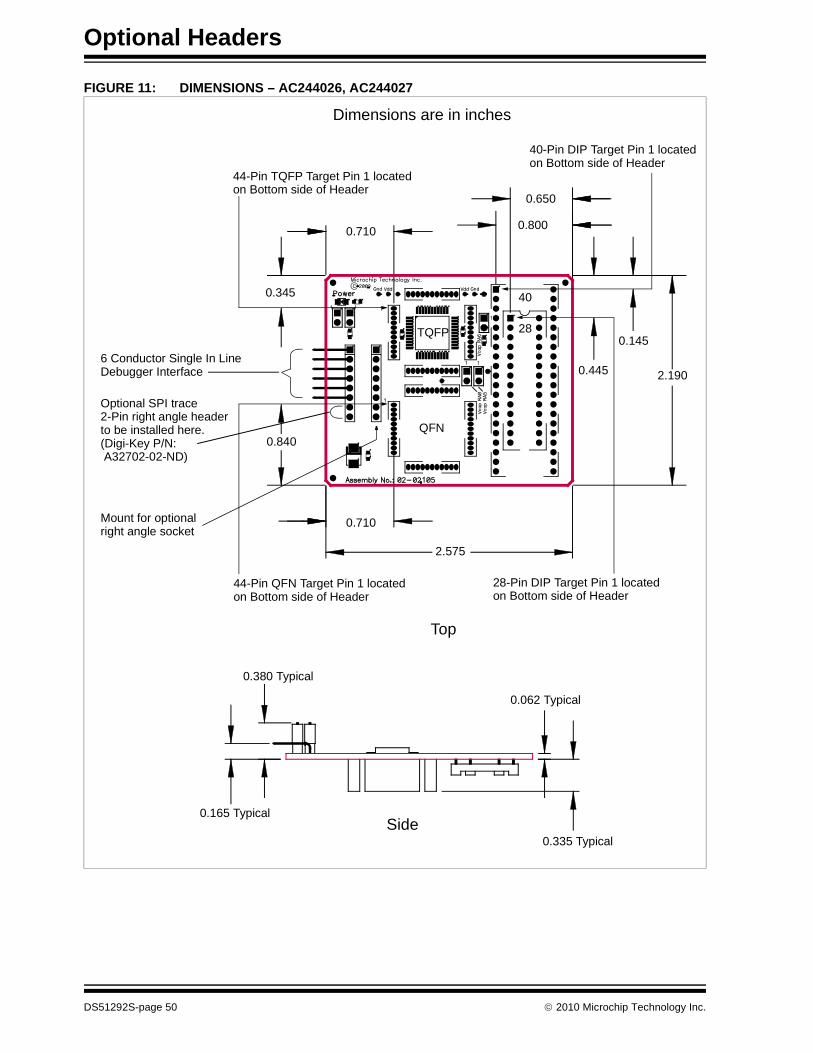
FIGURE 11: DIMENSIONS – AC244026, AC244027
Side
0.062 Typical
Top
0.335 Typical
0.380 Typical
0.165 Typical
0.710
0.710
2.575
0.345
0.840
0.650
0.800
0.445
0.145
2.190
TQFP
QFN
44-Pin TQFP Target Pin 1 locatedon Bottom side of Header
44-Pin QFN Target Pin 1 locatedon Bottom side of Header
28-Pin DIP Target Pin 1 locatedon Bottom side of Header
40-Pin DIP Target Pin 1 locatedon Bottom side of Header
6 Conductor Single In LineDebugger Interface
Optional SPI trace2-Pin right angle headerto be installed here.(Digi-Key P/N: A32702-02-ND)
28
40
Mount for optionalright angle socket
Dimensions are in inches
DS51292S-page 50 2010 Microchip Technology Inc.
Optional Headers
AC244033, AC244034
Header Identification
The header AC number is used for ordering the header. However, this number is not on the header board, as the board is often used for multiple headers by inserting different ICE/ICD devices. To identify this header board, use the following information.
Header Setup and Operation
For this header, there are no jumpers/switches. MPLAB IDE will use its selected device to choose the correct device to emulate.
Header Limitations
See the “Limitations” section in your debug tool on-line Help file for details.
Header Dimensions
The figures below list the dimensions for the header boards. Dimensions are design values in inches.
If the length and/or width of the header board is too large a footprint for the target board, consider using stand-offs, transition sockets or other extenders in the header connection socket to raise the header above the target.
Header ICE/ICD Device Board Assembly Number
AC244033 PIC18F14K22-ICE 02-02031
AC244034 PIC18LF14K22-ICE
2010 Microchip Technology Inc. DS51292S-page 51
Optional Headers
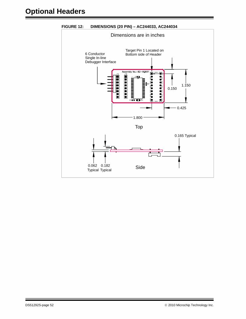
FIGURE 12: DIMENSIONS (20 PIN) – AC244033, AC244034
Side0.062Typical
0.165 Typical
0.182Typical
6 ConductorSingle In-lineDebugger Interface
Target Pin 1 Located onBottom side of Header
Dimensions are in inches
Top
1.800
1.1500.150
0.425
DS51292S-page 52 2010 Microchip Technology Inc.

Appendix A. Header Target Footprints
To connect a header board directly to a target board (without the use of a transition socket) the following information will be helpful.
• DIP Device Footprints
• TQFP/PLCC Device Footprints
DIP DEVICE FOOTPRINTS
DIP device adapter footprints shown will accept adapter plugs like Samtec series APA plugs. These plugs can be soldered in place during development/emulation and eliminate the need for any other sockets.
FIGURE 13: DIP FOOTPRINT
TQFP/PLCC DEVICE FOOTPRINTS
TQFP/PLCC device adapter footprints shown will accept board stackers like Samtec series DWM 0.050 Pitch Stackers. These stackers can be soldered in place during development/emulation and eliminate the need for any other sockets.
FIGURE 14: SINGLE-ROW TQFP/PLCC FOOTPRINT
0.100
C
UNLESS OTHERWISE SPECIFIED, DIMENSIONS ARE IN INCHES.
Drawing of DIP is 40-pin.
DIP C
8-Pin 0.300
14-Pin 0.300
18-Pin 0.300
20-Pin 0.300
28-Pin 0.300
40-Pin 0.600
0.028 DIA PLATED-THRU HOLES
0.050
0.800
0.800 UNLESS OTHERWISE SPECIFIED, DIMENSIONS ARE IN INCHES.
Drawing of device is 44-pin TQFP/PLCC.
0.028 DIA PLATED-THRU HOLES
2010 Microchip Technology Inc. DS51292S-page 53
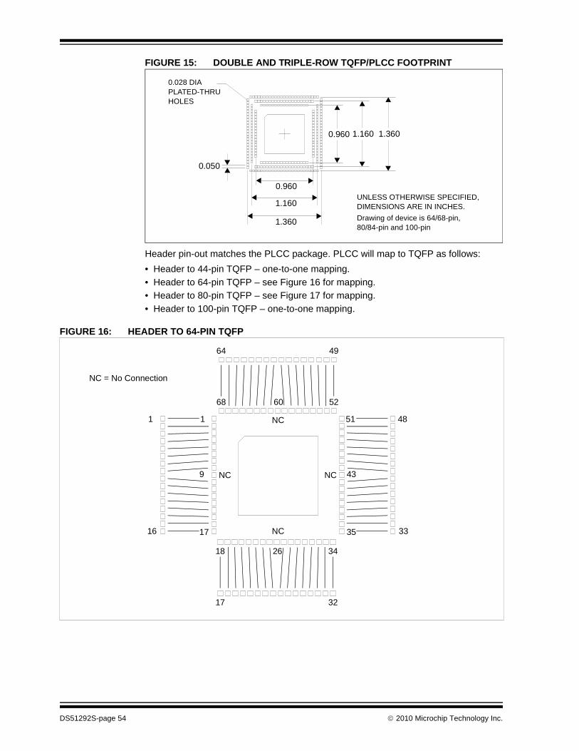
FIGURE 15: DOUBLE AND TRIPLE-ROW TQFP/PLCC FOOTPRINT
Header pin-out matches the PLCC package. PLCC will map to TQFP as follows:
• Header to 44-pin TQFP – one-to-one mapping.
• Header to 64-pin TQFP – see Figure 16 for mapping.
• Header to 80-pin TQFP – see Figure 17 for mapping.
• Header to 100-pin TQFP – one-to-one mapping.
FIGURE 16: HEADER TO 64-PIN TQFP
0.050
1.160
1.160
0.960
0.960
UNLESS OTHERWISE SPECIFIED, DIMENSIONS ARE IN INCHES.
Drawing of device is 64/68-pin, 80/84-pin and 100-pin
0.028 DIA PLATED-THRU HOLES
1.360
1.360
68 52
1
17
9
60
NC
NC
1
16
NC = No Connection
51
35
43NC
48
33
64 49
18 3426
17 32
NC
DS51292S-page 54 2010 Microchip Technology Inc.
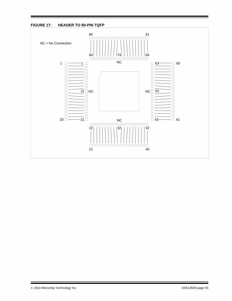
FIGURE 17: HEADER TO 80-PIN TQFP
84 64
22 42
1
21
63
43
80 61
11 53
32
74
NC
21 40
NC
60
41
NC NC
1
20
NC = No Connection
2010 Microchip Technology Inc. DS51292S-page 55

NOTES:
DS51292S-page 56 2010 Microchip Technology Inc.

Appendix B. Header Connections
The different types of header board connectors are shown here, as well as information on connecting development tools to the header.
• 6-Pin Modular Connector
• 8-Pin SIL Connector
• 6-Pin SIL Connector
• Modular-to-SIL Adapter
• Ordering Information
6-PIN MODULAR CONNECTOR
Header boards with 6-pin modular (RJ-11/ICSP) connectors can connect directly with the following tools:
• MPLAB REAL ICE in-circuit emulator (Standard Communication)
• MPLAB ICD 2 or 3
FIGURE 1: MODULAR CONNECTION
HeaderConnector
From
HeaderConnector
Tool
FromTool
TOP
SIDE
J1
TOP
SIDE
2010 Microchip Technology Inc. DS51292S-page 57
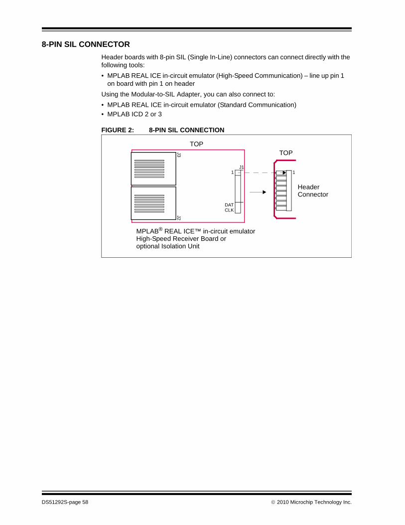
8-PIN SIL CONNECTOR
Header boards with 8-pin SIL (Single In-Line) connectors can connect directly with the following tools:
• MPLAB REAL ICE in-circuit emulator (High-Speed Communication) – line up pin 1 on board with pin 1 on header
Using the Modular-to-SIL Adapter, you can also connect to:
• MPLAB REAL ICE in-circuit emulator (Standard Communication)
• MPLAB ICD 2 or 3
FIGURE 2: 8-PIN SIL CONNECTION
MPLAB® REAL ICE™ in-circuit emulatorHigh-Speed Receiver Board or
TOP
HeaderConnector
optional Isolation Unit
TOP
11J1
DATCLK
J3J2
DS51292S-page 58 2010 Microchip Technology Inc.

6-PIN SIL CONNECTOR
Header boards with 6-pin SIL (Single In-Line) connectors can connect directly with the following tools:
• MPLAB REAL ICE in-circuit emulator (High-Speed Communication) – line up pin 1 on board with pin 1 on header
• PICkit 2 or 3 Debug Express
Using the Modular-to-SIL Adapter, you can also connect to:
• MPLAB REAL ICE in-circuit emulator (Standard Communication)
• MPLAB ICD 2 or 3
FIGURE 3: 6-PIN SIL CONNECTION
Note: No SPI trace is possible in this case because of the loss of DAT and CLK pins.
1J1
DATCLK
J3J2
PICkit 2 or 3
PICkit
TOP
TOP
HeaderConnector
HeaderConnector
MPLAB® REAL ICE™ in-circuit emulatorHigh-Speed Receiver Board oroptional Isolation Unit
TOP
TOP
1
11
2010 Microchip Technology Inc. DS51292S-page 59

MODULAR-TO-SIL ADAPTER
To adapt a 6-pin modular connector to an 8-pin SIL (Single In-Line) connector, you can use this adapter. You can also use this adapter for a 6-pin modular connector to an 6-pin SIL connector. In either case, line up pin 1 of J1 with pin 1 of the 6- or 8-pin header connector.
FIGURE 4: MODULAR-TO-SIL ADAPTER CONNECTION
ORDERING INFORMATION
To order the development tools and other hardware shown here, please refer to the table below.
Modular Connector SIL Connector
ICRST
VDD
ICDTICCKNC
123456
J2 J112345678
ICDT
ICCK
TP1 USD0TP2 USCK
6- or 8-PinHeaderConnector
FromTool
TOP11
J1
J2
TOP
TOP
NC
ICRSTVDD
TABLE B-1: MICROCHIP HARDWARE ORDERING NUMBERS
Hardware Order #
MPLAB® REAL ICE™ in-circuit emulator (Standard Communication) DV244005
MPLAB REAL ICE in-circuit emulator (High-Speed Communication) – Performance Pak
AC244002
MPLAB REAL ICE Isolation Unit (works with High-Speed Communication) AC244005
MPLAB ICD 2 DV164005
MPLAB ICD 3 DV164035
PICkit™ 2 Debug Express DV164121
PICkit 3 Debug Express DV164131
Modular-to-SIL Adapter AC164110
DS51292S-page 60 2010 Microchip Technology Inc.
Header Board Specification
APPENDIX C: REVISION HISTORY
C.1 Revision N (February 2006)
• Added Appendix A: Revision History
• Updated document to reflect support of additional tools
• Additional minor corrections throughout document text
C.2 Revision P (September 2007)
• Updated document to reflect support of additional tools
• Additional minor corrections throughout document text
C.3 Revision Q (December 2008)
• Added limitations to header setup sections as needed.
• Changed “ICD Headers” and “ICE Headers” to “Required Headers” and “Optional Headers” and move sections as necessary.
• Rearranged sections to organize by header (AC) number.
C.4 Revision R (April 2009)
• Added board dimensions
• Removed header pinouts
• Added board identification info
• Added “why use a header” section
• Added footprint appendix
• Changed MPLAB ICD 2 and MPLAB ICD 3 references to generic debug tool
• Added MPLAB REAL ICE in-circuit emulator and MPLAB ICD 3 as programmers
C.5 Revision S (July 2010)
• Added AC244028
• Added Header Connections chapter
• Added AC244033, AC244034
• Moved limitations to common Limitations file and added small section referencing Help files
• Added PIC12F617 to AC162083
2010 Microchip Technology Inc. DS51292S-page 61

Header Board Specification
NOTES:
DS51292S-page 62 2010 Microchip Technology Inc.

HEADER BOARD SPECIFICATION
Index
Numerics6-Pin Modular Connector ......................................... 576-Pin SIL Connector................................................. 598-Pin SIL Connector................................................. 58
AAC162050 .................................................................. 8AC162052 ................................................................ 10AC162053 ................................................................ 12AC162054 ................................................................ 12AC162055 ................................................................ 10AC162056 ................................................................ 10AC162057 ................................................................ 10AC162058 .................................................................. 8AC162059 ................................................................ 14AC162060 ................................................................ 16AC162061 ................................................................ 18AC162062 ................................................................ 32AC162064 ................................................................ 34AC162065 ................................................................ 36AC162066 ................................................................ 20AC162067 ................................................................ 39AC162070 ................................................................ 14AC162074 ................................................................ 39AC162078 ................................................................ 42AC162079 ................................................................ 32AC162083 ................................................................ 22AC162087 ................................................................ 32AC162088 ................................................................ 45AC162091 ................................................................ 32AC162094 ................................................................ 45AC162096 ................................................................ 14AC244022 ................................................................ 36AC244023 ................................................................ 24AC244024 ................................................................ 24AC244026 ................................................................ 48AC244027 ................................................................ 48AC244028 ................................................................ 26AC244033 ................................................................ 51AC244034 ................................................................ 51Additional Information ................................................ 5
CCalibration Bits ........................................................... 5
IICE vs. ICD ................................................................ 2
JJumper Settings 8, 10, 16, 20, 26, 32, 39, 43, 45, 48, 49
MModular Connector................................................... 57Modular-to-SIL Adapter............................................ 60MPLAB ICE 2000 ..................................................... 20
OOrdering Hardware................................................... 60
PPCM16YM0.............................................................. 20Performance............................................................... 5PIC10F200 ................................................................. 7PIC10F202 ................................................................. 7PIC10F204 ................................................................. 7PIC10F206 ................................................................. 7PIC10F220 ................................................................. 7PIC10F222 ................................................................. 7PIC12F508 ................................................................. 7PIC12F509 ................................................................. 7PIC12F510 ................................................................. 7PIC12F519 ................................................................. 7PIC12F609 ........................................................... 7, 22PIC12F615 ........................................................... 7, 22PIC12F617 ........................................................... 7, 22PIC12F629 ............................................................. 7, 8PIC12F635 ........................................................... 7, 10PIC12F675 ............................................................. 7, 8PIC12F683 ............................................................. 7, 8PIC12HV609 ........................................................ 7, 22PIC12HV615 ........................................................ 7, 22PIC16F505 ................................................................. 7PIC16F506 ................................................................. 7PIC16F526 ................................................................. 7PIC16F610 ........................................................... 7, 22PIC16F616 ........................................................... 7, 22PIC16F627A......................................................... 7, 12PIC16F628A......................................................... 7, 12PIC16F630 ........................................................... 7, 10PIC16F631 ........................................................... 7, 18PIC16F636 ........................................................... 7, 10PIC16F639 ........................................................... 7, 20PIC16F648A......................................................... 7, 12PIC16F676 ........................................................... 7, 10PIC16F677 ........................................................... 7, 18PIC16F684 ........................................................... 7, 10PIC16F685 ........................................................... 7, 18PIC16F687 ........................................................... 7, 18PIC16F688 ........................................................... 7, 10PIC16F689 ........................................................... 7, 18PIC16F690 ........................................................... 7, 18PIC16F716 ........................................................... 8, 12PIC16F785 ........................................................... 8, 16
2010 Microchip Technology Inc. DS51292S-page 63

Header Board Specification
PIC16HV610 ........................................................ 7, 22PIC16HV616 ........................................................ 7, 22PIC16HV785 ........................................................ 8, 16PIC18F1230 ....................................................... 29, 42PIC18F1330 ....................................................... 29, 42PIC18F13K22........................................................... 29PIC18F13K50............................................................. 8PIC18F14K22........................................................... 29PIC18F14K50............................................................. 8PIC18F24J10 ........................................................... 29PIC18F25J10 ..................................................... 29, 39PIC18F44J10 ........................................................... 29PIC18F45J10 ..................................................... 29, 39PIC18F63J11 ........................................................... 30PIC18F63J90 ........................................................... 30PIC18F64J11 ........................................................... 30PIC18F64J16 ........................................................... 30PIC18F64J90 ........................................................... 30PIC18F64J95 ........................................................... 30PIC18F65J10 ........................................................... 30PIC18F65J11 ........................................................... 30PIC18F65J15 ........................................................... 30PIC18F65J16 ........................................................... 30PIC18F65J50 ........................................................... 30PIC18F65J55 ........................................................... 30PIC18F65J90 ........................................................... 30PIC18F66J10 ........................................................... 30PIC18F66J11 ........................................................... 30PIC18F66J15 ........................................................... 30PIC18F66J16 ........................................................... 30PIC18F66J50 ........................................................... 30PIC18F66J55 ........................................................... 30PIC18F66J60 ........................................................... 30PIC18F66J65 ........................................................... 30PIC18F67J10 ........................................................... 30PIC18F67J11 ........................................................... 30PIC18F67J50 ........................................................... 30PIC18F67J60 ........................................................... 30PIC18F83J11 ........................................................... 30PIC18F83J90 ........................................................... 30PIC18F84J11 ........................................................... 30PIC18F84J16 ........................................................... 30PIC18F84J90 ........................................................... 30PIC18F84J95 ........................................................... 30PIC18F85J10 ........................................................... 30PIC18F85J11 ........................................................... 30PIC18F85J15 ........................................................... 30PIC18F85J16 ........................................................... 30PIC18F85J50 ........................................................... 30PIC18F85J55 ........................................................... 30PIC18F85J90 ........................................................... 30PIC18F86J10 ........................................................... 30PIC18F86J11 ........................................................... 30PIC18F86J15 ........................................................... 30PIC18F86J16 ........................................................... 30PIC18F86J50 ........................................................... 30PIC18F86J55 ........................................................... 30PIC18F86J60 ........................................................... 30PIC18F86J65 ........................................................... 30PIC18F87J10 ........................................................... 30
PIC18F87J11 ........................................................... 30PIC18F87J50 ........................................................... 30PIC18F87J60 ........................................................... 30PIC18F96J60 ........................................................... 30PIC18F96J65 ........................................................... 30PIC18F97J60 ........................................................... 30PIC18LF13K22......................................................... 29PIC18LF13K50........................................................... 8PIC18LF14K22......................................................... 29PIC18LF14K50........................................................... 8PIC18LF24J10 ......................................................... 29PIC18LF25J10 ................................................... 29, 39PIC18LF44J10 ......................................................... 29PIC18LF45J10 ................................................... 29, 39PIC24F04KA200 ........................................................ 8PIC24F04KA201 ........................................................ 8PIC24F08KA101 ...................................................... 31PIC24F08KA102 ...................................................... 31PIC24F16KA101 ...................................................... 31PIC24F16KA102 ...................................................... 31PIC24FJ128GA006 .................................................. 31PIC24FJ128GA008 .................................................. 31PIC24FJ128GA010 .................................................. 31PIC24FJ16GA002 .................................................... 31PIC24FJ16GA004 .................................................... 31PIC24FJ32GA002 .................................................... 31PIC24FJ32GA004 .................................................... 31PIC24FJ48GA002 .................................................... 31PIC24FJ48GA004 .................................................... 31PIC24FJ64GA002 .................................................... 31PIC24FJ64GA004 .................................................... 31PIC24FJ64GA006 .................................................... 31PIC24FJ64GA008 .................................................... 31PIC24FJ64GA010 .................................................... 31PIC24FJ96GA006 .................................................... 31PIC24FJ96GA008 .................................................... 31PIC24FJ96GA010 .................................................... 31PICDEM HPC Explorer Board.................................. 32Pin Count.............................................................. 7, 29Programming Non-ICD Devices ................................. 3
SSIL Connector, 6 Pin ................................................ 59SIL Connector, 8 Pin ................................................ 58Switch Settings......................................................... 18Switch Settings, Rotary ............................................ 22
TTransition Socket........................................................ 4
VVdd Max ............................................................... 7, 29Vddcore Max ........................................................ 7, 29
DS51292S-page 64 2010 Microchip Technology Inc.

Note the following details of the code protection feature on Microchip devices:
• Microchip products meet the specification contained in their particular Microchip Data Sheet.
• Microchip believes that its family of products is one of the most secure families of its kind on the market today, when used in the intended manner and under normal conditions.
• There are dishonest and possibly illegal methods used to breach the code protection feature. All of these methods, to our knowledge, require using the Microchip products in a manner outside the operating specifications contained in Microchip’s Data Sheets. Most likely, the person doing so is engaged in theft of intellectual property.
• Microchip is willing to work with the customer who is concerned about the integrity of their code.
• Neither Microchip nor any other semiconductor manufacturer can guarantee the security of their code. Code protection does not mean that we are guaranteeing the product as “unbreakable.”
Code protection is constantly evolving. We at Microchip are committed to continuously improving the code protection features of ourproducts. Attempts to break Microchip’s code protection feature may be a violation of the Digital Millennium Copyright Act. If such actsallow unauthorized access to your software or other copyrighted work, you may have a right to sue for relief under that Act.
Information contained in this publication regarding deviceapplications and the like is provided only for your convenienceand may be superseded by updates. It is your responsibility toensure that your application meets with your specifications.MICROCHIP MAKES NO REPRESENTATIONS ORWARRANTIES OF ANY KIND WHETHER EXPRESS ORIMPLIED, WRITTEN OR ORAL, STATUTORY OROTHERWISE, RELATED TO THE INFORMATION,INCLUDING BUT NOT LIMITED TO ITS CONDITION,QUALITY, PERFORMANCE, MERCHANTABILITY ORFITNESS FOR PURPOSE. Microchip disclaims all liabilityarising from this information and its use. Use of Microchipdevices in life support and/or safety applications is entirely atthe buyer’s risk, and the buyer agrees to defend, indemnify andhold harmless Microchip from any and all damages, claims,suits, or expenses resulting from such use. No licenses areconveyed, implicitly or otherwise, under any Microchipintellectual property rights.
2010 Microchip Technology Inc.
Trademarks
The Microchip name and logo, the Microchip logo, dsPIC, KEELOQ, KEELOQ logo, MPLAB, PIC, PICmicro, PICSTART, PIC32 logo, rfPIC and UNI/O are registered trademarks of Microchip Technology Incorporated in the U.S.A. and other countries.
FilterLab, Hampshire, HI-TECH C, Linear Active Thermistor, MXDEV, MXLAB, SEEVAL and The Embedded Control Solutions Company are registered trademarks of Microchip Technology Incorporated in the U.S.A.
Analog-for-the-Digital Age, Application Maestro, CodeGuard, dsPICDEM, dsPICDEM.net, dsPICworks, dsSPEAK, ECAN, ECONOMONITOR, FanSense, HI-TIDE, In-Circuit Serial Programming, ICSP, Mindi, MiWi, MPASM, MPLAB Certified logo, MPLIB, MPLINK, mTouch, Octopus, Omniscient Code Generation, PICC, PICC-18, PICDEM, PICDEM.net, PICkit, PICtail, REAL ICE, rfLAB, Select Mode, Total Endurance, TSHARC, UniWinDriver, WiperLock and ZENA are trademarks of Microchip Technology Incorporated in the U.S.A. and other countries.
SQTP is a service mark of Microchip Technology Incorporated in the U.S.A.
All other trademarks mentioned herein are property of their respective companies.
© 2010, Microchip Technology Incorporated, Printed in the U.S.A., All Rights Reserved.
Printed on recycled paper.
ISBN: 978-1-60932-377-6
DS51292S-page 65
Microchip received ISO/TS-16949:2002 certification for its worldwide headquarters, design and wafer fabrication facilities in Chandler and Tempe, Arizona; Gresham, Oregon and design centers in California and India. The Company’s quality system processes and procedures are for its PIC® MCUs and dsPIC® DSCs, KEELOQ® code hopping devices, Serial EEPROMs, microperipherals, nonvolatile memory and analog products. In addition, Microchip’s quality system for the design and manufacture of development systems is ISO 9001:2000 certified.

DS51292S-page 66 2010 Microchip Technology Inc.
AMERICASCorporate Office2355 West Chandler Blvd.Chandler, AZ 85224-6199Tel: 480-792-7200 Fax: 480-792-7277Technical Support: http://support.microchip.comWeb Address: www.microchip.com
AtlantaDuluth, GA Tel: 678-957-9614 Fax: 678-957-1455
BostonWestborough, MA Tel: 774-760-0087 Fax: 774-760-0088
ChicagoItasca, IL Tel: 630-285-0071 Fax: 630-285-0075
ClevelandIndependence, OH Tel: 216-447-0464 Fax: 216-447-0643
DallasAddison, TX Tel: 972-818-7423 Fax: 972-818-2924
DetroitFarmington Hills, MI Tel: 248-538-2250Fax: 248-538-2260
KokomoKokomo, IN Tel: 765-864-8360Fax: 765-864-8387
Los AngelesMission Viejo, CA Tel: 949-462-9523 Fax: 949-462-9608
Santa ClaraSanta Clara, CA Tel: 408-961-6444Fax: 408-961-6445
TorontoMississauga, Ontario, CanadaTel: 905-673-0699 Fax: 905-673-6509
ASIA/PACIFICAsia Pacific OfficeSuites 3707-14, 37th FloorTower 6, The GatewayHarbour City, KowloonHong KongTel: 852-2401-1200Fax: 852-2401-3431
Australia - SydneyTel: 61-2-9868-6733Fax: 61-2-9868-6755
China - BeijingTel: 86-10-8528-2100 Fax: 86-10-8528-2104
China - ChengduTel: 86-28-8665-5511Fax: 86-28-8665-7889
China - ChongqingTel: 86-23-8980-9588Fax: 86-23-8980-9500
China - Hong Kong SARTel: 852-2401-1200 Fax: 852-2401-3431
China - NanjingTel: 86-25-8473-2460Fax: 86-25-8473-2470
China - QingdaoTel: 86-532-8502-7355Fax: 86-532-8502-7205
China - ShanghaiTel: 86-21-5407-5533 Fax: 86-21-5407-5066
China - ShenyangTel: 86-24-2334-2829Fax: 86-24-2334-2393
China - ShenzhenTel: 86-755-8203-2660 Fax: 86-755-8203-1760
China - WuhanTel: 86-27-5980-5300Fax: 86-27-5980-5118
China - XianTel: 86-29-8833-7252Fax: 86-29-8833-7256
China - XiamenTel: 86-592-2388138 Fax: 86-592-2388130
China - ZhuhaiTel: 86-756-3210040 Fax: 86-756-3210049
ASIA/PACIFICIndia - BangaloreTel: 91-80-3090-4444 Fax: 91-80-3090-4123
India - New DelhiTel: 91-11-4160-8631Fax: 91-11-4160-8632
India - PuneTel: 91-20-2566-1512Fax: 91-20-2566-1513
Japan - YokohamaTel: 81-45-471- 6166 Fax: 81-45-471-6122
Korea - DaeguTel: 82-53-744-4301Fax: 82-53-744-4302
Korea - SeoulTel: 82-2-554-7200Fax: 82-2-558-5932 or 82-2-558-5934
Malaysia - Kuala LumpurTel: 60-3-6201-9857Fax: 60-3-6201-9859
Malaysia - PenangTel: 60-4-227-8870Fax: 60-4-227-4068
Philippines - ManilaTel: 63-2-634-9065Fax: 63-2-634-9069
SingaporeTel: 65-6334-8870Fax: 65-6334-8850
Taiwan - Hsin ChuTel: 886-3-6578-300Fax: 886-3-6578-370
Taiwan - KaohsiungTel: 886-7-536-4818Fax: 886-7-536-4803
Taiwan - TaipeiTel: 886-2-2500-6610 Fax: 886-2-2508-0102
Thailand - BangkokTel: 66-2-694-1351Fax: 66-2-694-1350
EUROPEAustria - WelsTel: 43-7242-2244-39Fax: 43-7242-2244-393Denmark - CopenhagenTel: 45-4450-2828 Fax: 45-4485-2829
France - ParisTel: 33-1-69-53-63-20 Fax: 33-1-69-30-90-79
Germany - MunichTel: 49-89-627-144-0 Fax: 49-89-627-144-44
Italy - Milan Tel: 39-0331-742611 Fax: 39-0331-466781
Netherlands - DrunenTel: 31-416-690399 Fax: 31-416-690340
Spain - MadridTel: 34-91-708-08-90Fax: 34-91-708-08-91
UK - WokinghamTel: 44-118-921-5869Fax: 44-118-921-5820
WORLDWIDE SALES AND SERVICE
01/05/10