hd/sd 6-channel digital video switcher se-2200
TRANSCRIPT

SE-2200
HD/SD 6-CHANNELDIGITAL VIDEO SWITCHER
Instruction manual

2
Table of Contents
FCC COMPLIANCE STATEMENT ..................................................................................................... 4
WARNINGS AND PRECAUTIONS .................................................................................................... 4
WARRANTY .................................................................................................................................. 5
STANDARD WARRANTY ............................................................................................................................. 5 THREE YEAR WARRANTY ........................................................................................................................... 5
DISPOSAL ..................................................................................................................................... 5
INTRODUCTION ............................................................................................................................ 6
FEATURES ............................................................................................................................................... 6 SYSTEM DIAGRAM .................................................................................................................................... 7
CONNECTIONS AND CONTROLS .................................................................................................... 7
CONNECTING THE SE-2200 MAIN UNIT TO THE CONTROL PANEL ..................................................................... 8 MAIN UNIT – FRONT PANEL ...................................................................................................................... 8 MAIN UNIT - REAR PANEL ......................................................................................................................... 9
Rear Panel Connections .................................................................................................................. 9 CONTROL PANEL OVERVIEW .................................................................................................................... 12
Keyboard Controls ........................................................................................................................ 13 MENU OPTIONS .................................................................................................................................... 19
MULTI SCREEN MODES ............................................................................................................... 21
SE-2200 VIDEO LAYERS ............................................................................................................... 22
PICTURE IN PICTURE FUNCTION .................................................................................................. 23
PIP SETTINGS ........................................................................................................................................ 23 PIP PRESET AND PIP PROGRAM ................................................................................................................ 23 ASSIGNING A VIDEO SOURCE INPUT TO A PIP ................................................................................................ 23
DSK FUNCTION ........................................................................................................................... 25
DSK SETTINGS ....................................................................................................................................... 25 DSK PVW AND DSK PGM ..................................................................................................................... 25 ASSIGNING AN INPUT TO THE DSK PVW CHANNEL FOR KEYING ....................................................................... 25
TC-200 MODE & CG-200 OVERLAY INPUT FROM A LAPTOP .......................................................... 26
AUDIO FUNCTION ....................................................................................................................... 28
OVERVIEW ............................................................................................................................................ 28 AUDIO FOLLOW VIDEO ..................................................................................................................... 28 AUDIO FIXED ..................................................................................................................................... 29 AUDIO MENU OPTIONS – DE-EMBEDDING SDI OR HDMI AUDIO .................................................................... 29 WORKING WITH A FIXED OR SINGLE AUDIO SOURCE ........................................................................................ 30 SWITCHING BETWEEN DIFFERENT EMBEDDED AUDIO SOURCES ......................................................................... 31
HOW TO RE-CALIBRATE THE SE-2200 T-BAR ................................................................................. 32
GPI CONNECTIONS ...................................................................................................................... 33
SE-2200 TALLY OUTPUTS ............................................................................................................. 34
DIMENSIONS .............................................................................................................................. 35

3
SPECIFICATIONS ......................................................................................................................... 36
SERVICE & SUPPORT ................................................................................................................... 40
Disclaimer of Product & Services The information offered in this instruction manual is intended as a guide only. At all times, Datavideo Technologies will try to give correct, complete and suitable information. However, Datavideo Technologies cannot exclude that some information in this manual, from time to time, may not be correct or may be incomplete. This manual may contain typing errors, omissions or incorrect information. Datavideo Technologies always recommend that you double check the information in this document for accuracy before making any purchase decision or using the product. Datavideo Technologies is not responsible for any omissions or errors, or for any subsequent loss or damage caused by using the information contained within this manual. Further advice on the content of this manual or on the product can be obtained by contacting your local Datavideo Office or dealer.

4
FCC Compliance Statement
This device complies with part 15 of the FCC rules. Operation is subject to the following two conditions: (1) This device may not cause harmful interference, and (2) This device must accept any interference received, including interference that may cause
undesired operation.
Warnings and Precautions
1. Read all of these warnings and save them for later reference. 2. Follow all warnings and instructions marked on this unit. 3. Unplug this unit from the wall outlet before cleaning. Do not use liquid or aerosol
cleaners. Use a damp cloth for cleaning. 4. Do not use this unit in or near water. 5. Do not place this unit on an unstable cart, stand, or table. The unit may fall, causing serious
damage. 6. Slots and openings on the cabinet top, back, and bottom are provided for ventilation. To ensure
safe and reliable operation of this unit, and to protect it from overheating, do not block or cover these openings. Do not place this unit on a bed, sofa, rug, or similar surface, as the ventilation openings on the bottom of the cabinet will be blocked. This unit should never be placed near or over a heat register or radiator. This unit should not be placed in a built-in installation unless proper ventilation is provided.
7. This product should only be operated from the type of power source indicated on the marking label of the AC adapter. If you are not sure of the type of power available, consult your Datavideo dealer or your local power company.
8. Do not allow anything to rest on the power cord. Do not locate this unit where the power cord will be walked on, rolled over, or otherwise stressed.
9. If an extension cord must be used with this unit, make sure that the total of the ampere ratings on the products plugged into the extension cord do not exceed the extension cord rating.
10. Make sure that the total amperes of all the units that are plugged into a single wall outlet do not exceed 15 amperes.
11. Never push objects of any kind into this unit through the cabinet ventilation slots, as they may touch dangerous voltage points or short out parts that could result in risk of fire or electric shock. Never spill liquid of any kind onto or into this unit.
12. Except as specifically explained elsewhere in this manual, do not attempt to service this product yourself. Opening or removing covers that are marked “Do Not Remove” may expose you to dangerous voltage points or other risks, and will void your warranty. Refer all service issues to qualified service personnel.
13. Unplug this product from the wall outlet and refer to qualified service personnel under the following conditions: a. When the power cord is damaged or frayed; b. When liquid has spilled into the unit; c. When the product has been exposed to rain or water; d. When the product does not operate normally under normal operating conditions. Adjust
only those controls that are covered by the operating instructions in this manual; improper adjustment of other controls may result in damage to the unit and may often require extensive work by a qualified technician to restore the unit to normal operation;
e. When the product has been dropped or the cabinet has been damaged; f. When the product exhibits a distinct change in performance, indicating a need for service.

5
Warranty
Standard Warranty
Datavideo equipment are guaranteed against any manufacturing defects for one year from the date of purchase.
The original purchase invoice or other documentary evidence should be supplied at the time of any request for repair under warranty.
The product warranty period begins on the purchase date. If the purchase date is unknown, the product warranty period begins on the thirtieth day after shipment from a Datavideo office.
Damage caused by accident, misuse, unauthorized repairs, sand, grit or water is not covered under warranty.
Viruses and malware infections on the computer systems are not covered under warranty. Any errors that are caused by unauthorized third-party software installations, which are not
required by our computer systems, are not covered under warranty. All mail or transportation costs including insurance are at the expense of the owner. All other claims of any nature are not covered. Cables and batteries are not covered under warranty. Warranty only valid in the country or region of purchase. Your statutory rights are not affected.
Three Year Warranty
All Datavideo products purchased after July 1st, 2017 are qualified for a free two years extension to the standard warranty, providing the product is registered with Datavideo within 30 days of purchase.
Certain parts with limited lifetime expectancy such as LCD panels, DVD drives, Hard Drive, Solid State Drive, SD Card, USB Thumb Drive, Lighting, Camera module, PCIe Card are covered for 1 year.
The three-year warranty must be registered on Datavideo's official website or with your local Datavideo office or one of its authorized distributors within 30 days of purchase.
Disposal
For EU Customers only - WEEE Marking This symbol on the product or on its packaging indicates that this product must not be disposed of with your other household waste. Instead, it is your responsibility to dispose of your waste equipment by handing it over to a designated collection point for the recycling of waste electrical and electronic equipment. The separate collection and recycling of your waste equipment at the time of disposal will help
to conserve natural resources and ensure that it is recycled in a manner that protects human health and the environment. For more information about where you can drop off your waste equipment for recycling, please contact your local city office, your household waste disposal service or the shop where you purchased the product.
CE Marking is the symbol as shown on the left of this page. The letters "CE" are the abbreviation of French phrase "Conformité Européene" which literally means "European Conformity". The term initially used was "EC Mark" and it was officially replaced by "CE Marking" in the Directive 93/68/EEC in 1993. "CE Marking" is now
used in all EU official documents.

6
Introduction The SE-2200 6 input multi-definition switcher is perfect for live production, religious worship, meetings or conference purposes. It is a technically smart and cost effective portable broadcast-quality switcher. SE-2200 is a solution that comes with great features such as 6x6 SDI genlocked Matrix, Dual PIP and built-in title overlay system that works with entry level Datavideo CG systems, or other graphics programmes. SE-2200 consists of 6 HD-SDI video inputs or with a combination of 4 HD-SDI and 2 HDMI inputs; all of the inputs are re-assignable, thus it is able to adapt to your needs. One of the HDMI inputs can be used to accept video from a PC/Laptop computer to work with built-in title overlay system such as Datavideo's CG solutions, including CG-200.
Features
6 input HD broadcast quality switcher Ideal for live production venues, religious worship, meetings or conference purposes Video Inputs: 6 x HD-SDI, 2 x HDMI (CH 5 & 6) Audio Inputs: 4 x XLR Configurable Video Outputs: 6x HD-SDI (Program, Aux, Multi-View) Multi-View Outputs: 2 x HDMI 6x6 SDI Genlocked Matrix, Dual PIP and a built-in title creator system that works with Datavideo
CG systems, PowerPoint and other graphics programmes

7
System Diagram

8
Connections and Controls
Connecting the SE-2200 Main Unit to the Control Panel
Use D-SUB Cable to connect SE-2200 main unit to SE-2200 control unit.
SE-2200 Control Panel
SE-2200 Main Unit
Main Unit – Front Panel
The front panel on the SE-2200 main unit has a grille for airflow cooling fans. Please do not block or cover this grille as the unit may overheat. This grille should also be kept free of dust. The front panel can be removed by using the four thumbscrews. A soft brush or cloth can then be used to clean the grille before attaching it back to the unit. The power button starts and shuts down both the SE-2200 main unit and its attached keyboard.
D-Sub Cable

9
Main Unit - Rear Panel
1. Video Input 1~4 – HD-SDI 9. Grounding Terminal
2. Tally Output Connector 10. 4pin XLR Power Input Connector (12V)
3. Connect the SE-2200 Keyboard 11. Mini Switch 2
4. Ethernet Port for external Control (PC) 12. Service Port - Load FS file & Firmware Updates
5. RS-232/422 Connector & Mini Switch 1 (TBD) 13. Multi View Outputs – HDMI
6. GPI Output Connector 14. Video Output 1~6 – HD-SDI
7. 3pin XLR Audio Inputs 1~4 15. Input 6 – HD-SDI / HDMI (User Defined)
8. 3pin XLR Audio Outputs 1 / 2 16. Input 5 – HD-SDI / HDMI (User Defined)
Rear Panel Connections
Video Inputs
The SE-2200 can be supplied with up to six video input channels.
The SE-2200 has six BNC input connectors and two input HDMI ports. Input channels 5 and 6 are optionally set up either as BNC SDI or HDMI. Note: Please activate the SE-2200 MENU and select
INPUT 5 AND 6 MODE to set the required input
connection.
Tally Output The SE-2200 Tally Output port provides bi-colour tally information to a number of other Datavideo products, such as the ITC-100 eight channel talkback system or the Datavideo TLM range of monitors.

10
Console Port This 9pin D-Sub connector is used to connect the Control Panel / Keyboard to the rear of the SE-2200 Main Processing unit.
Ethernet Port For external PC control only
RS-232 / RS-422 Remote This port is not active under current firmware.
GPI The GPI socket can be used for simple external control.
Note: Please activate the SE-2200 MENU and select
GPI SETTINGS to set up the required GPI connection.
AUDIO Inputs Supports four channels XLR Balanced Audio Input for embedding.
AUDIO Outputs Supports two channels XLR Balanced Audio output. (de-embedded audio from any of the digital video sources)
Grounding Terminal When connecting this unit to any other component, make sure that it is properly grounded by connecting this terminal to an appropriate point. When connecting, use the socket and be sure to use wire with
a cross-sectional area of at least 1.0 mm2.

11
DC Input Connect the supplied 12V 3A PSU to this 4pin XLR socket. Pin 1 = GND ( - ) Pin 2 = NC Pin 3 = NC Pin 4 = VCC ( + )
Mini Switch 2 For firmware upgrades, switch both switches to the upper position. For Fast Start, please select lower position.
Service Port This RJ45 Ethernet port is used to update the SE-2200 firmware, or upload logos and images using the SEConfig software.
SDI Video Outputs The six BNC output connectors are user defined SDI outputs. Each of these SDI outputs has the option to be:
1. Program 2. Program logo free 3. Program logo & titles free 4. Preview 5. Aux1, 2, 3 or 4 6. Multi screen
Note: Please activate the SE-2200 MENU and select OUTPUT SOURCE to set the output source.
HDMI Multi-View Outputs SE-2200 Multi-view monitoring is available across two HDMI monitors. These HDMI outputs can be used to monitor video and audio in a number of different configurations.
This Multi-view is supplied from the HDMI connection(s)
on the rear panel. When connected to two compatible
HDMI monitors a variety of multi-image layouts is
possible.
Note: HDMI multi-view output is 1080i. Note that both
HDMI outputs are Identical (cloned).

12
Control Panel Overview
1. HDMI Multi Screen [MSCR] or Program [PGM]
2. PC Control
3. Audio Fixed 4. Cross Point Video, Audio, Frame Store [FS] & Aux
5. Audio Follows Video 6. Menu access
7. Wipe Transition Selection 8. Function Keys F1~F4
9. PIP Preview [PVW] & Program [PGM] 10. DSK Preview [PVW] & Program [PGM]
11. Logos 1 & 2 and clock selection 12. Fade to Black [FTB]
13. Speed Selection [Auto Take Transitions] 14. Wipe Function
15. CUT & AUTO TAKE 16. Mix / Dissolve Function
17. Freeze Function 18. T-Bar – Manual Transitions
19. Program row – On Air 20. Preset Row – Preview / Next source
21. Timer Function – Multi view only

13
Keyboard Controls
Program and Preset rows
The Program row of buttons is the active channel, this is the live output. The active channel
will appear as the Program Output. You can switch or CUT from one video source to another
directly on the Program row. You will see the multi view Program output change as you press
different keys along this top row of buttons.
The Preset row is the cued channel; this channel will appear in the Preview window. The Preset row
selection decides which input will be transitioned next when using any of the transition controls.
BK
Black background – the black background, for use on the
Program and Preset row.
BG
Background button – assigns a background colour or colour
bars for use on the Program and Preset row.
Note: Please activate the SE-2200 MENU and select
CONSOLE SETTINGS to set the background colour.
MSCR/PGM Switch HDMI outputs between Multi Screen [MSCR] view
and Program [PGM] view.
PC Control Press this key, to allow a computer to remotely control the
SE-2200, or when using the supplied SEConfig software to
load Frame Store [FS] stills and Logos.
Audio Fixed For more details, please see the AUDIO FIXED section.

14
FS – Frame Store Button The SE-2200 CH1~6 video channels, each of these channels has its own Frame Store. Each of these Frame Stores can hold one still image. This still image can be called into the production by using the FS button located at the top left corner of the SE-2200 Control Panel / Keyboard. The FS button allows the user to toggle between the still image of the Frame Store or the live video input also connected to that same video channel.
How to choose live video input or Frame Store
1. First press and hold down the FS button. The Preset row of input sources will light.
2. While still holding down the FS button, press the required input on the Preset row.
3. The input button will flash to confirm the Frame Store is selected.
The contents of each Frame Store are uploaded to the SE-2200 from a PC. The supplied SEConfig software is used to do this. This selection will also be confirmed on the HDMI Multi-view, with the selected channel showing the live input or frame store image.
AUX Source Selection The SE-2200 has four user defined AUX SDI outputs; one or all of these outputs can be set up as an auxiliary (AUX) output via a menu option. The AUX output source can be quickly selected in the following way.
1. First press and hold down the AUX button. The Program row of input sources will light.
2. While still holding down the AUX button, press the required input on the Program row*. The Preset row of input sources will light.
3. While still holding down the AUX button, press the required input on the Preset row.
4. The input button will flash to confirm the AUX source is selected. *Repeat this for the other aux output if required.
XPT Video Assigning video source, channel setting depended on your selection. The XPT Video source can be quickly selected in the following way.
1. First press and hold down the XPT VIDEO button. The Program row of input sources will light.
2. While still holding down this XPT VIDEO button, press the required input on the Program
row. The Preset row of input sources will light.
3. While still holding down the XPT VIDEO button, press the required input on the Preset row. 4. The input button will flash to confirm the video source is selected.

15
XPT Audio Assigning audio source, channel setting depended on your selection. The XPT Audio source can be quickly selected in the following way.
1. First press and hold down the XPT AUDIO button. The Program row of input sources will light.
2. While still holding down this XPT AUDIO button, press the required input on the Program
row. The Preset row of input sources will light.
3. While still holding down the XPT AUDIO button, press the required input on the Preset row. 4. The input button will flash to confirm the audio source is selected.
Audio Follow Video For more details, please see the AUDIO FOLLOW VIDEO
section.
Menu Control Press the MENU button in the SE-2200 function section to enter the System Configuration Menu. Press the UP, DOWN, LEFT, and RIGHT arrow buttons to navigate the menu options and to change values. Use the ENTER button to save and confirm any setting that has been amended.
WIPES The SE-2200 has 17 user defined wipe buttons, and a BDR button. All wipes can have an optional colour border applied. The wipe border width and colour are chosen within the menu system. Transitions can be performed manually using the T-Bar or automatically by using the SPEED and AUTO TAKE buttons.
Vertical Wipe Left to Right. Vertical Wipe Right to Left.
Horizontal Wipe Top to Bottom. Horizontal Wipe Bottom to Top.
Box Wipe from outside edges to
Centre.
Box Wipe from Centre to outside edges.

16
Upper Left corner Wipe to Lower
Right corner
Upper Right corner Wipe to Lower Left corner
Lower Left corner Wipe to Upper
Right corner
Lower Right corner Wipe to Upper Left corner
Circle Wipe from Centre to outside
edges
Circle Wipe from outside edges to Centre
Vertical Wipes from Centre to Left
and Right sides
Vertical Wipes from Left and Right sides to Centre
Horizontal Wipes from Centre to Top
and Bottom
Horizontal Wipes from Top and Bottom to Centre
Diamond Wipe from Centre to
outside edges
Border: Enable / Disable wipe border
FUNCTION buttons (F1~F4) These function buttons are not yet active under the current firmware.
PIP Preview and PIP Program When looking at the top right corner of the SE-2200 Control Panel / Keyboard there are four PIP keys. These are labelled Program and Preview. The upper PIP1 and PIP2 keys relate to activating Picture In Picture images on the Program outputs. The lower PIP1 and PIP2 keys relate to activating Picture In Picture images on the Multi-view and Preview outputs (as well as allowing the assigning of a PIP source)
For more details, please see Picture in Picture Function.
DSK Preview and DSK Program When looking at the top right corner of the SE-2200 Control Panel / Keyboard there are two DSK keys. These are labelled Program and Preview. The upper DSK key relates to activating Down Stream Keying on the Program outputs. The lower DSK key relate to activating Down Stream Keying on the Multi-view or Preview outputs. (as well as allowing the assigning of the key source) For more details, please see DSK Function.

17
LOGO 1/2 The LOGO 1 and LOGO 2 buttons are used to display pre-selected logos on the SE-2200 Preview and Program outputs. When the button is active the selected logo is shown. These logos are selected from the switcher’s memory and positioned using a menu option.
LOGO 2 or CLOCK The user cannot display LOGO 2 and CLOCK at the same time. Instead use LOGO 1 and CLOCK together or use LOGO 1 and LOGO 2 together.
FTB Fade To Black, this button fades the current video program source to black. When pressed again it acts in reverse from complete black to the currently selected program video source.
SPEED There are three speed buttons which can be defined by the user. By pressing a speed button the user is choosing the rate of transition or time taken when using the AUTO TAKE button. Note: Please activate the SE-2200 MENU and select CONSOLE SETTINGS to set up SPEED BUTTON SETTING.
WIPE The WIPE button is selected when a wipe effect transition between the selected Program and Preset sources is required. This WIPE effect is produced by then moving the T-Bar manually or by pressing the AUTO button.
CUT This performs a simple immediate switch from the current main source to the selected sub source. The selected transition wipe or MIX is not used. AUTO TAKE This performs an automated switch from the current program source to the selected Preview source. The selected transition wipe or MIX will also be used. The timing of the transition is set by the chosen Speed button.
MIX Pressing this button selects a basic A/B Dissolve for the next transition.

18
FREEZE Freeze the program source image or return to live video of the selected program source. Press and hold down this button and the Preset bus will light. While pressing this button select the desired channel to grab a still or frozen image.
T-Bar This performs a manually controlled transition from the current program source to the selected Preset source. The selected transition wipe or dissolve will be used. When the T-Bar has travelled as far as it can go the transition between sources is complete. The T-Bar has indicators next to it which light when the transition is complete. The T-Bar can be operated in one of two modes which are chosen by a menu option.
TIMER In some mixing or switching applications it is useful to have a countdown timer. It could be that the input is a pre-recorded video clip and you need to know when to be ready to switch away from it.
This countdown timer function is only seen in the status area of the HDMI multi-view output near the normal Clock function. The timer can be selected for one input channel, several channels or all channels. When the TIMER button is active and the user switches to a selected input channel the countdown starts on the HDMI multi-view. The value of the countdown is set in Minutes and Seconds (MM:SS). A maximum countdown of sixty minutes [60:00] is possible. However, the initial default is 15 seconds [00:15]. When the countdown reaches zero, the user must then switch or transition to another input channel. The switcher will not automatically change to the selected Preset source at the end of the countdown.
How to set up the TIMER Countdown Settings
1. On the switcher’s keyboard, select the video source to be set up for TIMER on the PRESET row.
2. Press the MENU key and select the ON PREVIEW SETTING to find the COUNT DOWN SETTING.
3. Count Down is on can be switched ON or OFF.
4. Count Down Value can be set to the required length of time in Minutes and Seconds [MM:SS].

19
5. Press the ENTER key to save your chosen settings, and then exit the MENU Mode.
6. Press the TIMER key so it is on and then transition to the chosen PRESET channel. The countdown will start in the status area near the clock function.
7. Select the next source that needs to be set up for countdown timer on the PRESET row by following steps 2 to 6.
Note: The Count Down will only start if the selected Preset and Program sources are different. The Count Down will not start if Program and Preset sources are both set for the same input.
Menu Options
When the ENTER button is pressed the Main Menu list is displayed on the HDMI 1 Multi-view output. This section covers the Menu options in the order that they appear on the
SE-2200 HDMI 1 Multi-view. These settings may also appear in more detail
elsewhere in this instruction manual. Options may vary depending on the
firmware version in use.
Once the chosen setting has been confirmed with the ENTER button it
is stored within the switchers non-volatile memory.
* The following menu table applies when the switcher is in HD 1080i mode.
Version No Where xx.xx is the version number
1 Mode (Video Format) 1080i or 720P
2 On Preview settings
Video input adjustment
Brightness Range 072 to 184
Contrast Range 36 to 92
Saturation Range 36 to 92
Apeture 0~3
Y-C Delay 0~7
Set to Nominal Reset to default values
Audio input adjustment Level -60 ~ +60
Set to Nominal Tick to reset
Count Down Settings
Count Down is on See Timer section on page 15.
Count Down Value
Value is set in minutes and seconds [MM:SS] Default 15 sec or 00:15 Max 1 hour or 60:00
3 Inputs 5 and 6 mode
Input 5 SDI Tick and enter to select
HDMI Tick and enter to select
Input 6 HDMI Color Mode
RGB
YUV 422 Tick to select
YUV 444 TC-200 mode

20
4 Output Sources Output 1~6
User has a choice of: Program Program Logo Free Program Logo & DSK Free Preview Aux 1~4 Multi Screen
5 Aux Selection Aux 1~4 Inputs 1~6
6 Audio Settings
Dynamic Range (dB) 18 or 24
Audio Crosspoints Input 1~6 Value 1~6
SDI de-embed Audio Input 1~6 Group 1~4 & Pair 1 or 2
HDMI de-embed Audio Input 5 or Input 6 Pair 1, 2, 3 or 4
Audio re-embed setup Output 1~6 Pair 1, 2, 3 or 4
Audio Mixing Type X type or Y Type Tick to select
7 PIP Settings PIP 1 PIP 2
Horizontal Position 000~107
Vertical Position 000~108
Window size 01~33
Border Width 00~35
Border Color 01~08
8 Logo Settings Logo 1 Logo 2
Logo Selection 1~8
Horizontal Position 000~110
Vertical Position 000~124
9 Clock Settings
Horizontal Position 000~110
Vertical Position 000~124
Set Hours 00~24
Set Minutes 00~59
Clear seconds
10 DSK Settings
DSK
See DSK section Luma Key Mode
Luma Key Level
11 Wipe Border Settings Wipe 1~17 Width 0~4
Color 1~8
12 Multi Screen Setup
Multi Screen Mode Variant A/ B/ C See Multi Screen mode section below
Multi Screen Audio setup Preview/ Program Audio
Audio Level Indicator ON/ OFF
13 Console Settings
T-Bar Audio Mixing Type Follow T-Bar / By the END
T-Bar Mode One way mode / Two way mode
Speed Button Setting Speed 1/ 2/ 3 4 ~ 64 Frames
BG Button Color 1 ~ 9 where 9 = colour bars
Button Settings Brightness 000 ~ 004
Backlight is on On/ Off
1KHz to Bars On/ Off
14 GPI Settings
Input Select 0 ~ 6 Channel 1~6 0=GPI function disabled
Time Delay Mode
01 ~ 75 Delay time can be set between 1 ~ 75 frames Level Pulse
15 Remote Control Ethernet
Tick to select DVIP Board
16 Factory Settings Tick selection to enable – Reset all menu settings to factory default values

21
Multi Screen modes
The SE-2200 HDMI Multi view outputs can be configured using menu option 12. Multi Screen Setup. Three Multi Screen layouts are available, variant A, B or C. This Multi Screen output can also be assigned to any of the six SDI outputs using menu option 4. Output Sources.
Multi Screen - Variant A
Multi Screen - Variant B Multi Screen - Variant C

22
SE-2200 Video Layers
The SE-2200 is a Standard Definition or High Definition Digital Video Switcher and as well as mixing
video and audio sources it has additional functions such as Picture in Picture (PIP), DSK LUMA KEY and
LOGOs.
Before attempting to use the SE-2200’s PIP, DSK LUMA KEY and LOGO functions it may help to first
understand the order of the video layers at the SE-2200 Program (PGM) outputs.
The Background video layer is the normal video layer when mixing and switching with the SE-2200.
It occupies the whole screen area of the Program output. This layer can be hidden or part hidden by
the PIP, DSK and LOGO layers in front of it.
The PIP 1 layer does not occupy the whole screen and is shown in front of the Background video layer
when enabled. In some setups the PIP 1 image can be hidden behind the PIP 2 image. This is not a
fault. Change the position or size of the PIP 1 or PIP 2 image if required.
The PIP 2 layer does not occupy the whole screen and is shown in front of the Background video
and PIP 1 layers when enabled. In some setups the PIP 1 image can hide the PIP 2 image. Change the
position or size of the PIP 2 or PIP 1 image if required.
The DSK layer can occupy the whole screen. If set up incorrectly this layer can stop the video layers
behind it from being seen properly. Re-adjust your DSK 1 settings or switch off the DSK1 function
on the SE-2200 to restore the video behind it.
The LOGO and Clock layer does not occupy the whole screen and all other layers are visible
through it. A logo if positioned incorrectly can partially hide an important part of the video, PIP or CG
LUMA KEY layers. Typically logos or station ID bugs are placed in a corner of the screen.
NB: Where possible prepare and position the upper video layer elements in advance of the live
production starting to avoid them appearing on the program output incorrectly.
Most broadcast networks have guidelines and advice on the use of video, images, music, logos and
on screen text so it is best to check beforehand when planning a production. Do not use copyright
protected content until you have the relevant permissions. Information on royalty free video,
images and music is widely available, speak to your local dealer or search for advice on the
internet.

23
Picture in Picture Function
The SE-2200 Picture in Picture function allows you to place one or two smaller PIP images over a chosen full size background image. The smaller PIP images can be set to pre-defined sizes and positioned almost anywhere within the Preset/Program screen area. These PIP windows can also have a coloured border applied, and can be brought into the production with a default PIP dissolve transition.
PIP Settings
Before trying to activate the PIP function it is best to understand how to set up or choose the right options for your production. Press the ENTER Key in the MENU area of the SE-2200 keyboard. Navigate to the PIP Settings option using the down arrow key. The PIP menu options provided here are:
PIP Settings
PIP1
PIP2
Horizontal Position = 000 to 107 (Left to right) Vertical Position = 000 to 108 (Lower to Upper) Window Size = 1 (small) to 33 (large) Border Width = 0 (OFF), 1 (Thin) to 5 (Thick) Border Color 1 = White, 2 = Yellow, 3 = Light Blue, 4 = Green,
5 = Purple, 6 = Red, 7 = Dark Blue, 8 = Black.
PIP Preset and PIP Program
When looking at the top right corner of the SE-2200 Control Panel / Keyboard there are four PIP keys. These are labelled Program and Preset.
The upper PIP1 and PIP2 keys relate to activating Picture In Picture images on the Program outputs.
The lower PIP1 and PIP2 keys relate to activating Picture In Picture images on the Multi-view or Preview outputs.
Assigning a video source input to a PIP
Using the lower PIP1 or PIP2 PVW buttons you can assign a selected video input to the chosen PIP video layer.
1. First press and hold down the required PIP PVW button on the lower row. The Preset row of input sources will light.
2. While still holding down the PIP PVW button, press to select the required video input from the Preset row.
3. The input button will flash to confirm it is selected.
This selection will also be confirmed on the HDMI Multi-view, with a PIP1 or PIP2 label shown next to the selected input image.

24
4. Pressing PIP PGM will take the chosen PIP1 or PIP2 to air with a fade in transition.

25
DSK Function
The SE-2200 has two Down Stream buttons (DSK PGM, DSK PVW). This means it is able to take a key source video input and replace the white or black parts of this image with the video from another source. If the input video carries an alpha channel it is also possible to key in this way too.
DSK Settings
Before trying to activate the DSK function it is best to understand how to set up or choose the
right options for your production well in advance of the production.
Press the ENTER Key in the MENU area of the SE-2200 keyboard. Navigate to the DSK Settings option using the down arrow key. The DSK menu options provided here are:
DSK Settings Titles + α Channel [DSK] Luma Key Mode Luma Key Level
Luma Key Level 0 (black) to 255 (white)
DSK PVW and DSK PGM
When looking at the top right corner of the SE-2200 Control Panel / Keyboard there are two DSK
buttons. These are labelled Program and Preset.
The upper DSK PGM key relate to activating Down Stream Keying on the Program outputs.
The lower DSK PVW key relate to activating Down Stream Keying on the Multi-view or Preview
outputs.
Assigning an input to the DSK PVW channel for keying
Using the lower DSK PVW button you can assign a selected video input to the chosen DSK video layer.
1. First press and hold down the DSK PVW button on the lower row. The Preset row of input sources will light.
2. While still holding down the DSK PVW button, press to select the required input from the Preset row.
3. The input will flash to confirm it is selected.
This selection will also be confirmed on the HDMI Multi-view, with a DSK label shown next to the selected input image.
4. Pressing DSK PGM will take the DSK overlay to air with a fade in transition.

26
TC-200 Mode & CG-200 overlay input from a laptop
The CG-200 Character Generator software allows the producer to create professional overlays with a
Windows laptop or Windows PC from which the CG-200 outputs a computer generated video stream
via an HDMI interface. This software works perfectly with the SE-2200’s built-in title overlay system
(TC-200) if subtitles are a requirement in your production environment. However, please note that
the following hardware restrictions may apply when using this feature.
The built-in title overlay system (TC-200) has a better compatibility performance with ATI and
Intel VGA graphics cards.
Compatibility issue such as color difference may occur when used with NVIDIA graphics cards.
Visit Datavideo’s official website http://www.datavideo.com/product/CG-200 to download a free
copy of the latest CG-200 software. Then follow the steps outlined below to set up the CG-200
Character Generator software with the SE-2200.
1. Use the SE-2200 menu option Inputs 5 and 6 mode to change input 6 from SDI input to HDMI.
2. Use the up arrow key to select HDMI. A tick will appear. Press ENTER to save this setting.
3. Within the menu option Inputs 5 and 6 mode there is a third option for HDMI colour mode which should be set to TC-200 Mode.
4. Now use the SE-2200 menu option DSK Settings and select DSK
5. Connect the laptop running the CG-200 Windows software to HDMI input 6 via HDMI.
6. Once the software is launched the switcher may not automatically show the extended Windows desktop. This is normal.
7. Use the CG-200 HDMI On / Off button to toggle the CG overlay output On and Off.

27
8. Load your prepared CG-200 project and click the playback button on the same toolbar.
9. Pressing DSK PGM will take the DSK CG-200 overlay to air with a fade in transition.
Note: A separate manual is also provided for help with preparing CG-200 projects.
28
AUDIO Function
Overview
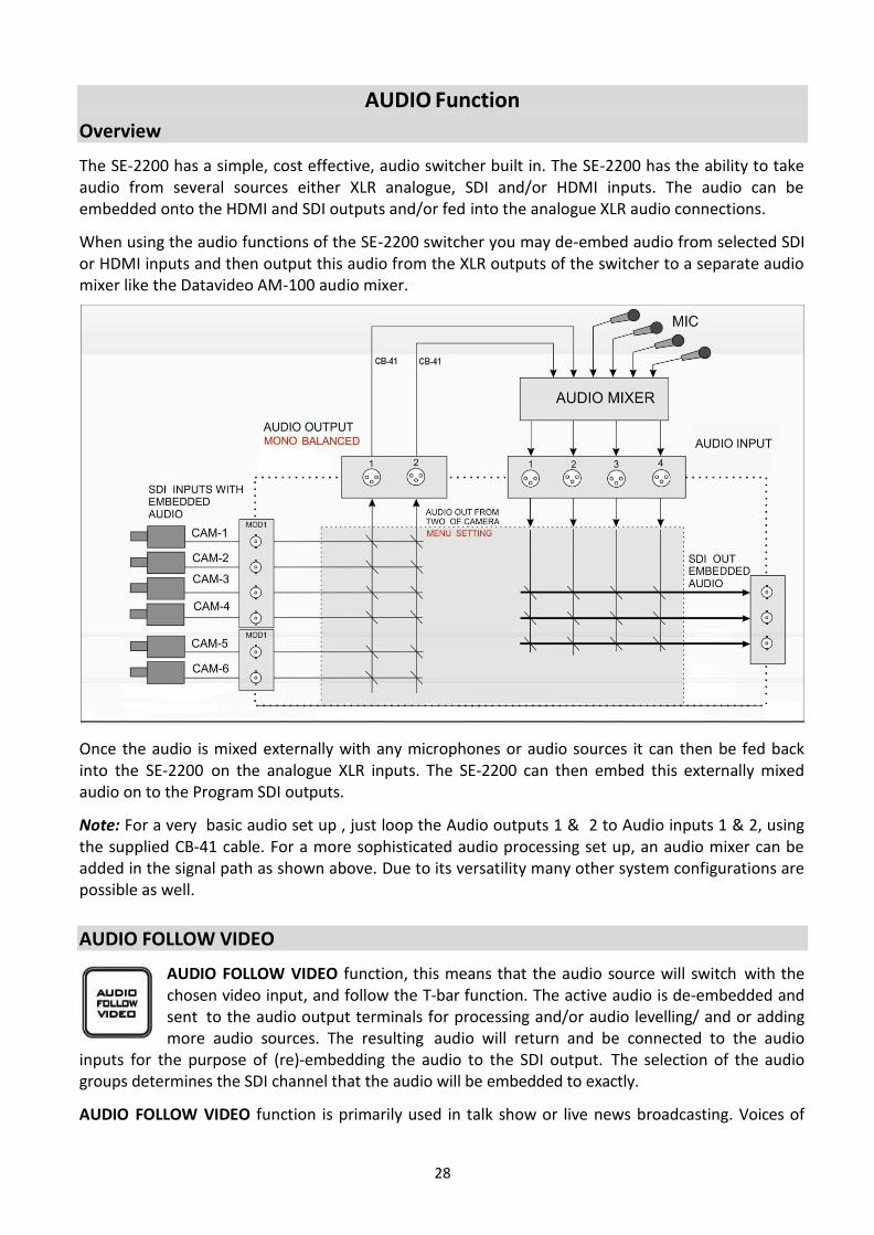
The SE-2200 has a simple, cost effective, audio switcher built in. The SE-2200 has the ability to take audio from several sources either XLR analogue, SDI and/or HDMI inputs. The audio can be embedded onto the HDMI and SDI outputs and/or fed into the analogue XLR audio connections.
When using the audio functions of the SE-2200 switcher you may de-embed audio from selected SDI or HDMI inputs and then output this audio from the XLR outputs of the switcher to a separate audio mixer like the Datavideo AM-100 audio mixer.
Once the audio is mixed externally with any microphones or audio sources it can then be fed back into the SE-2200 on the analogue XLR inputs. The SE-2200 can then embed this externally mixed audio on to the Program SDI outputs.
Note: For a very basic audio set up , just loop the Audio outputs 1 & 2 to Audio inputs 1 & 2, using the supplied CB-41 cable. For a more sophisticated audio processing set up, an audio mixer can be added in the signal path as shown above. Due to its versatility many other system configurations are possible as well.
AUDIO FOLLOW VIDEO
AUDIO FOLLOW VIDEO function, this means that the audio source will switch with the chosen video input, and follow the T-bar function. The active audio is de-embedded and sent to the audio output terminals for processing and/or audio levelling/ and or adding more audio sources. The resulting audio will return and be connected to the audio
inputs for the purpose of (re)-embedding the audio to the SDI output. The selection of the audio groups determines the SDI channel that the audio will be embedded to exactly.
AUDIO FOLLOW VIDEO function is primarily used in talk show or live news broadcasting. Voices of

29
different guests are directly collected by the corresponding cameras, thus, when the program director switches between different guests, the video is switched at the same time with voice of the guest during program broadcasting. This function is definitely an indispensable function during live broadcasting.
AUDIO FIXED
The AUDIO FIXED method, allows a user to manually select which audio input can be matched to the SDI video input and assigned to the audio output terminals, which is shown in the example below:
The table below illustrates that the sound of video input 1 is used for all individual video inputs.
AUDIO CROSSPOINTS
INPUT 1 (BUTTON 1) 1
INPUT 2 (BUTTON 2) 1
INPUT 3 (BUTTON 3) 1
INPUT 4 (BUTTON 4) 1
INPUT 5 (BUTTON 5) 1
INPUT 6 (BUTTON 6) 1
The AUDIO FIXED function is primarily used during big (concert) events and (wedding) parties. One camera picks up the audio of the audience and/or ambience of that video input 1, which is assigned to be sent to the audio output. The other cameras are assigned to this same audio of video input 1. When the operator switches between the video sources, the sound of video input 1 remains on all the time.
Audio Menu Options – De-embedding SDI or HDMI audio
Using the following SE-2200 menu options, audio can be selected from the SDI or HDMI video inputs.
SDI INPUTS Embedded Audio Inputs 1 to 6 User choice of Group 1,2,3 or 4 Pair 1 or 2
HDMI in Embedded Audio Pair Input 5 or 6 User choice of Pair 1,2,3 or 4
As each HD-SDI source can have up to sixteen channels of embedded audio, and HDMI eight channels, we need to choose the audio channels with the options above and by the following reference tables. Normal Stereo resides at channels 1 and 2.
SDI Embedded Audio Table
Group Stereo Pair Channel
Group 1 Pair 1 1
2
SE-2200 Assigned Audio Output Channel SE-2200 Audio INPUT Channel

30
Pair 2 3
4
Group 2
Pair 3 5
6
Pair 4 7
8
Group 3
Pair 5 9
10
Pair 6 11
12
Group 4
Pair 7 13
14
Pair 8 15
16
HDMI Embedded Audio Table
Pair Channel
Pair 1 1
2
Pair 2 3
4
Pair 3 5
6
Pair 4 7
8
In some cases, there may only be two channels of audio associated with the video: Pair 1.
Working with a fixed or single audio source Example 1: We have two mono mics (channels 1 & 2) connected to an HD camera. These embedded audio channels are then sent from this camera along with the HD-SDI video to the SE-2200 switcher. If we want to only hear these two audio channels regardless of the video channel used then we would set up the switcher in the following way.
Press the ENTER key in the MENU area of the SE-2200 keyboard to display the on screen menu and then enter AUDIO CROSSPOINTS of the AUDIO SETTINGS option.
Change the de-embedded audio setup in the menu system to show a value of 1 for each video input channel. Press the ENTER key to store the audio values chosen for each video input.
Change the audio (re-)embedding setup in the switcher’s menu system to show a value of Group 1.

31
Press the ENTER key to store the audio values chosen for each video input.
Now exit the menu by pressing any wipe key.
Locate the AUDIO FIXED button at the top left corner of the keyboard. Enable the AUDIO FIXED status by pressing the AUDIO FIXED button. Confirm that the AUDIO FIXED has been enabled by checking the status area of the HDMI multi-view. The button will be backlit red.
Switching between different embedded audio sources Example 2: We have two mono mics with each connected to a different HD camera. These embedded audio channels are then sent from this camera along with the HD-SDI video to the SE-2200 switcher. If we want to hear the audio from each camera as the video channels are switched, audio follows video, then we would set up in the following way.
Press the ENTER key in the MENU area of the SE-2200 keyboard to display the on screen menu and then enter AUDIO CROSSPOINTS of the AUDIO SETTINGS option.
Change the Audio Association settings in the menu system to set input 1 audio source to 1, input 2 audio source to 2, input 3 audio source to 3 and etc. Press the ENTER key to store the audio values chosen for each video input.
Change the SDI Embedded Audio setting in the switcher’s menu system to show a value of Group 1 and Pair 1. Press the ENTER key to store the audio values chosen for each video input.
Now exit the menu by pressing the menu key and locate the AUDIO FIXED button in the crosspoint area of the keyboard.
Select the AUDIO FOLLOW VIDEO status with this button when looking at the status area of the HDMI multi-view. The button will be off. The status area is located just below or near the Preview image on the HDMI multi-view monitor.
When switching between the video sources the audio sources will also change. We can choose how the audio will change sources, whether it is a clean cut (immediate switch) or some sort of transitioned change (cross fade or fade out & in). To do this we would need to set up with the following menu options.
Auto Audio Mixing Type
User choice of
X type or V type Tick selection
X type = A/B cross fade V type = Fade out A then fade in B
T-Bar Audio Mixing Type
Tick selection of
Follow auto audio mixing type (use above option) By the end (clean cut or immediate audio switch)
32
How to Re-calibrate the SE-2200 T-Bar
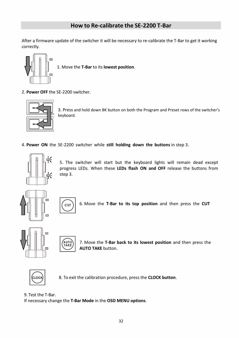
After a firmware update of the switcher it will be necessary to re-calibrate the T-Bar to get it working correctly.
1. Move the T-Bar to its lowest position.
2. Power OFF the SE-2200 switcher. 3. Press and hold down BK button on both the Program and Preset rows of the switcher’s keyboard.
4. Power ON the SE-2200 switcher while still holding down the buttons in step 3.
5. The switcher will start but the keyboard lights will remain dead except progress LEDs. When these LEDs flash ON and OFF release the buttons from step 3.
6. Move the T-Bar to its top position and then press the CUT button.
7. Move the T-Bar back to its lowest position and then press the AUTO TAKE button.
8. To exit the calibration procedure, press the CLOCK button.
9. Test the T-Bar. If necessary change the T-Bar Mode in the OSD MENU options.

33
GPI Connections The SE-2200 can control external recorder/playback devices like the HDR-60/70 via simple contact closure GPI switch. The interface supports both “trigger pulse” and level “Hi/ low” system. The GPI interface is a 3.5mm Jack Socket which is situated on the rear panel of the SE-2200. Contact closure between the Outer and Inner contacts on the jack plug will trigger a user selected event. Power is supplied by the SE- 2200 and is less than 5V DC.
This GPI socket can also be used as a socket to trigger record or playback events with other equipment such as the Datavideo HDR-70 recorder.
SAFETY FIRST The cabling required needs to be designed specifically to connect the SE-2200 to the
chosen record or playback device as they are not all the same. The cabling required can be
made by yourself or a competent technician. Please speak with your Dealer or local Datavideo
office to get further help and advice.

34
SE-2200 Tally Outputs
The SE-2200 has a D-sub 25 pin female tally output
port. These connections provide bi-colour tally
information to a number of other Datavideo products,
such as the ITC-100 eight channel talkback system and
the TLM range of LCD Monitors.
These ports are open collector ports and as such
do not provide power to tally light circuits.
Dielectric strength: Max. DC
24V Current: Max. 50mA
The pin outputs are defined as follows:
Pin No. Signal name Input/Output Description of signal
1 Program 1 Open collector output Tally output of input video Program 1
2 Program 2 Open collector output Tally output of input video Program 2
3 Program 3 Open collector output Tally output of input video Program 3
4 Program 4 Open collector output Tally output of input video Program 4
5 Program 5 Open collector output Tally output of input video Program 5
6 Program 6 Open collector output Tally output of input video Program 6
13 GND Ground Ground
14 Preview 1 Open collector output Tally output of input video Preview 1
15 Preview 2 Open collector output Tally output of input video Preview 2
16 Preview 3 Open collector output Tally output of input video Preview 3
17 Preview 4 Open collector output Tally output of input video Preview 4
18 Preview 5 Open collector output Tally output of input video Preview 5
19 Preview 6 Open collector output Tally output of input video Preview 6

35
Dimensions

36
Specifications
Model Name SE-2200
Product Name HD/SD 6-Channel Digital Video Switcher
Video Standard HD & SD
Video Format
1080i 50/59.94/60Hz 720p 50/59.94/60Hz 576i 50Hz 480i 59.94Hz
Video Processing SDI: 4:2:2 HDMI: YUV 4:2:2 10 bit, RGB: 4:4:4
Input Routable / Crosspoint
All 6, repeatable
Video Input 6 x HD-SDI 2 x HDMI (CH5/6)
Mix HD & SD Source N/A
Computer Graphical Interface
2 via HDMI
Video Output
6 x SDI output assignable:
Multiview
Program
Preview
Clean Program
AUX 1 – 4 2 x HDMI output assignable
Multiview
Program
Down-Converted Output N/A
Built-in Multi-View Monitoring Out
2 x HDMI
Analogue Audio Input 4 x Balanced XLR
Analogue Audio Output 2 x Balanced XLR
Digital Embedded Audio Support
Input: 16 Channels Output: 4 Channels
Audio Delay Calibration N/A
A+V Switching Yes
Chromakey N/A
Title Creator Yes, download CG-200 software for free
USK N/A
DSK 2 x DSK supporting Lumakey & Linear key (Key / Fill)
Picture in Picture 2

37
Logo Insertion 2 (or 1 logo/1 clock)
Still Store 6
Effects FTB, Cut, 8 Wipe with border
Transition Preview PIP & DSK
Sync / Reference In / Out Built-in Genlock (Internal)
Tally Output 1 x D-sub 25pin, Dual Color
PC Remote Control Ethernet (free Windows software) RS-422/RS-232
Built-in Audio Mixer N/A
Special Features 6x6 Matrix Seamless Switch Built-in TC-200 CG Interface
Chassis 2 units, 2RU Rack-Mount Mainframe
Dimensions (LxWxH) 433 x 312 x 76 mm (Switcher) 432 x 252 x 88 mm (Main Unit)
Weight 6.1 kg
Power DC 12V 32W
Accessory CB-60/61/62 / CB-46/47
Operating Temperature 0°C - 40°C [32°F - 104°F]

38
Notes

39
Notes

Oct-23.2020 Version E7
Datavideo Technologies Co., Ltd. All rights reserved 2020
www.datavideo.com/product/SE-2200