hdcp 2.2 v1 - xilinx - all programmable xilinx® hdcp 2.2 solution consists of the following: •...
TRANSCRIPT

HDCP 2.2 v1.0
Product Guide
Vivado Design Suite
PG249 October 5, 2016
HDCP 2.2 v1.0 2PG249 October 5, 2016 www.xilinx.com
Table of ContentsIP Facts
Chapter 1: OverviewHDCP 2.2 Over HDMI . . . . . . . . . . . . . . . . . . . . . . . . . . . . . . . . . . . . . . . . . . . . . . . . . . . . . . . . . . . . . . . 5Applications . . . . . . . . . . . . . . . . . . . . . . . . . . . . . . . . . . . . . . . . . . . . . . . . . . . . . . . . . . . . . . . . . . . . . . 7Licensing and Ordering Information . . . . . . . . . . . . . . . . . . . . . . . . . . . . . . . . . . . . . . . . . . . . . . . . . . . 7
Chapter 2: Product SpecificationIP Cores . . . . . . . . . . . . . . . . . . . . . . . . . . . . . . . . . . . . . . . . . . . . . . . . . . . . . . . . . . . . . . . . . . . . . . . . . 10Standards . . . . . . . . . . . . . . . . . . . . . . . . . . . . . . . . . . . . . . . . . . . . . . . . . . . . . . . . . . . . . . . . . . . . . . . 12Performance and Resource Utilization. . . . . . . . . . . . . . . . . . . . . . . . . . . . . . . . . . . . . . . . . . . . . . . . 13Port Descriptions . . . . . . . . . . . . . . . . . . . . . . . . . . . . . . . . . . . . . . . . . . . . . . . . . . . . . . . . . . . . . . . . . 13
Chapter 3: Designing with the IPGeneral Design Guidelines . . . . . . . . . . . . . . . . . . . . . . . . . . . . . . . . . . . . . . . . . . . . . . . . . . . . . . . . . 17Clocking. . . . . . . . . . . . . . . . . . . . . . . . . . . . . . . . . . . . . . . . . . . . . . . . . . . . . . . . . . . . . . . . . . . . . . . . . 28Resets . . . . . . . . . . . . . . . . . . . . . . . . . . . . . . . . . . . . . . . . . . . . . . . . . . . . . . . . . . . . . . . . . . . . . . . . . . 28
Chapter 4: Design Flow StepsCustomizing and Generating the IP . . . . . . . . . . . . . . . . . . . . . . . . . . . . . . . . . . . . . . . . . . . . . . . . . . 29Constraining the IP. . . . . . . . . . . . . . . . . . . . . . . . . . . . . . . . . . . . . . . . . . . . . . . . . . . . . . . . . . . . . . . . 31Simulation . . . . . . . . . . . . . . . . . . . . . . . . . . . . . . . . . . . . . . . . . . . . . . . . . . . . . . . . . . . . . . . . . . . . . . 32Synthesis and Implementation . . . . . . . . . . . . . . . . . . . . . . . . . . . . . . . . . . . . . . . . . . . . . . . . . . . . . . 32
Appendix A: Application Software DevelopmentDevice Drivers . . . . . . . . . . . . . . . . . . . . . . . . . . . . . . . . . . . . . . . . . . . . . . . . . . . . . . . . . . . . . . . . . . . 33
Appendix B: Upgrading
Appendix C: DebuggingFinding Help on Xilinx.com . . . . . . . . . . . . . . . . . . . . . . . . . . . . . . . . . . . . . . . . . . . . . . . . . . . . . . . . . 43Debug Tools . . . . . . . . . . . . . . . . . . . . . . . . . . . . . . . . . . . . . . . . . . . . . . . . . . . . . . . . . . . . . . . . . . . . . 44Hardware Debug . . . . . . . . . . . . . . . . . . . . . . . . . . . . . . . . . . . . . . . . . . . . . . . . . . . . . . . . . . . . . . . . . 45
Send Feedback

HDCP 2.2 v1.0 3PG249 October 5, 2016 www.xilinx.com
Appendix D: Additional Resources and Legal NoticesXilinx Resources . . . . . . . . . . . . . . . . . . . . . . . . . . . . . . . . . . . . . . . . . . . . . . . . . . . . . . . . . . . . . . . . . . 47References . . . . . . . . . . . . . . . . . . . . . . . . . . . . . . . . . . . . . . . . . . . . . . . . . . . . . . . . . . . . . . . . . . . . . . 47Revision History . . . . . . . . . . . . . . . . . . . . . . . . . . . . . . . . . . . . . . . . . . . . . . . . . . . . . . . . . . . . . . . . . . 48Please Read: Important Legal Notices . . . . . . . . . . . . . . . . . . . . . . . . . . . . . . . . . . . . . . . . . . . . . . . . 48
Send Feedback

HDCP 2.2 v1.0 4PG249 October 5, 2016 www.xilinx.com Product Specification
IntroductionThe Xilinx® High-bandwidth Digital Content Protection (HDCP) 2.2 transmitter and receiver implement the HDCP 2.2 specification which defines how to securely send audiovisual content from an HDCP 2.2 protected transmitter to HDCP 2.2 compliant downstream receivers. HDCP 2.2 supersedes the HDCP 1.4 protocol and does not provide backward compatibility. Typically, HDCP 2.2 is used to encrypt content at Ultra-High Definition (UHD) while HDCP 1.4 is the legacy content protection scheme used at lower resolutions. The IP supports the HDCP 2.2 over HDMI mapping. The IP is not a standalone core, but instead is integrated as part of the HDMI Transmitter and Receiver Subsystems.
Features• HDCP 2.2 Transmitter/Receiver over HDMI
• HDCP 2.2 Authentication and key exchange
• Encryption/Decryption of Video, Audio, and Data Island Packets
• Acceleration of RSA decryption for authentication
• Support for resolutions up to 2160p (UHD) at 60 fps
• Repeater and converter support
• System Renewability Message (SRM) and Revocation
IP Facts
IP Facts Table
Core Specifics
Supported Device Family(1)
UltraScale+™, including Zynq® UltraScale+UltraScale™Zynq-7000
7 series
Supported User Interfaces AXI4-Lite, AXI4-Stream,
ResourcesPerformance and Resource Utilization TXPerformance and Resource Utilization RX
Provided with CoreDesign Files Encrypted RTL
Example Design Not Provided
Test Bench Not Provided
Constraints File XDC
Simulation Model Not Provided
Supported S/W Driver(2) Standalone
Tested Design Flows(3)
Design Entry Vivado® Design Suite
Simulation For supported simulators, see theXilinx Design Tools: Release Notes Guide.
Synthesis Vivado Synthesis
SupportProvided by Xilinx at the Xilinx Support web page
Notes: 1. For a complete list of supported devices, see the Vivado IP
catalog.2. Standalone driver details can be found in the SDK directory
(<install_directory>/SDK/<release>/data/embeddedsw/doc/xilinx_drivers.htm). Linux OS and driver support information is available from the Xilinx Wiki page.
3. For the supported versions of the tools, see theXilinx Design Tools: Release Notes Guide.
Send Feedback

HDCP 2.2 v1.0 5PG249 October 5, 2016 www.xilinx.com
Chapter 1
OverviewThe Xilinx® HDCP 2.2 solution consists of the following:
• HDCP 2.2 Transmitter
• HDCP 2.2 Receiver
The HDCP 2.2 transmitter and receiver can only be instantiated as part of the Xilinx HDMI Transmitter/Receiver Subsystems (see the HDMI 1.4/2.0 Transmitter Subsystem v1.0 Product Guide (PG235) [Ref 1] and the HDMI 1.4/2.0 Receiver Subsystem v1.0 Product Guide (PG236) [Ref 2] for more information). The following sections give an overview of how HDCP 2.2 is used within the HDMI subsystems.
HDCP 2.2 Over HDMIHDCP can be enabled as part of the Xilinx HDMI Transmitter and Receiver Subsystem in the following configurations:
• No HDCP
• HDCP 1.4 only
• HDCP 2.2 only
• HDCP 1.4 and HDCP 2.2
Figure 1-1 shows a configuration of the HDMI transmitter where both HDCP 1.4 and 2.2 are enabled. With both HDCP protocols enabled the HDMI Subsystem configures itself in the cascade topology where the HDCP 1.4 and HDCP 2.2 are connected back-to-back. The HDCP Egress interface of the HDMI transmitter sends unencrypted audiovisual data, which gets encrypted by the active HDCP block and sent back into the HDMI transmitter over the HDCP Ingress interface for transmission over the link. The HDMI transmitter subsystem ensures that only one of the HDCP protocols are active at any given time and the other is passive.
Send Feedback

HDCP 2.2 v1.0 6PG249 October 5, 2016 www.xilinx.com
Chapter 1: Overview
Similarly, the HDMI receiver is able to decrypt data received over the link from an HDCP 1.4 or 2.2 transmitter as shown in Figure 1-2. The HDMI transmitter or receiver subsystem should be customized to enable only the required HDCP protocol. Although HDCP 2.2 can be used to encrypt video at any resolution it is important to note that HDCP transmitters choose their encryption scheme based on the supported resolution of the receiver. For example, the HDCP transmitter might decide to use HDCP 1.4 for resolutions below 2160p60Hz and HDCP 2.2 for resolutions at or above 2160p60Hz. Applications must take the supported use cases into consideration when deciding which protocol to enable in the HDMI subsystem.
X-Ref Target - Figure 1-1
Figure 1-1: HDCP 2.2 over HDMI Transmitter
HDMI Transmitter
HDCP 2.2 Transmitter
(Active)
HDCP 1.4 Transmitter(Passive)
AXI4-StreamHDCP Egress(Unencrypted)
AXI4-StreamHDCP Ingress
(Encrypted)
AXI4-Stream Video TMDS Link
AXI4-Stream Audio
HDMI Transmitter Subsystem
Send Feedback

HDCP 2.2 v1.0 7PG249 October 5, 2016 www.xilinx.com
Chapter 1: Overview
ApplicationsThe Xilinx HDCP 2.2 transmitter and receiver are seamlessly integrated into the Xilinx HDMI transmitter and receiver subsystems for simple integration into user applications and rapid deployment. The Xilinx HDCP 2.2 solution is composed of a transmitter and receiver and software driver. Resolutions up to 2160p60Hz (UHD) are supported.
The HDCP 2.2 transmitter and receiver implement the AES-128 cipher along with support for particular parts of the authentication and key exchange process such as random number generation and acceleration for RSA decryption. The random numbers used during authentication and key exchange are generated by the hardware Random Number Generator (RNG) providing true randomness. The true random numbers generated are based on real world phenomenon such as temperature and process variation rather than algorithmic or mathematical models typically used to generate pseudo-randomness. The Montgomery Multiplier (MMULT) is implemented in the HDCP 2.2 receiver to accelerate the RSA modular exponentiation process for decryption of the master key.
Licensing and Ordering Information
License CheckersIf the IP requires a license key, the key must be verified. The Vivado® design tools have several license checkpoints for gating licensed IP through the flow. If the license check
X-Ref Target - Figure 1-2
Figure 1-2: HDCP 2.2 over HDMI Receiver
HDMI Receiver
HDCP 2.2 Receiver(Active)
HDCP 1.4 Receiver(Passive)
AXI4-Stream
HDCP EgressAXI4-Stream(Encrypted)
HDCP IngressAXI4-Stream(Decrypted)
AXI4-Stream VideoTMDS Link
AXI4-Stream Audio
HDMI Receiver Subsystem
Send Feedback

HDCP 2.2 v1.0 8PG249 October 5, 2016 www.xilinx.com
Chapter 1: Overview
succeeds, the IP can continue generation. Otherwise, generation halts with error. License checkpoints are enforced by the following tools:
• Vivado synthesis
• Vivado implementation
• write_bitstream (Tcl command)
IMPORTANT: IP license level is ignored at checkpoints. The test confirms a valid license exists. It does not check IP license level.
License TypeThis Xilinx IP module is provided under the terms of the Xilinx Core License Agreement. The module is shipped as part of the Vivado® Design Suite. For full access to all core functionalities in simulation and in hardware, you must purchase a license for the core. Contact your local Xilinx sales representative for information about pricing and availability.
Information about other Xilinx LogiCORE IP modules is available at the Xilinx Intellectual Property page. For information on pricing and availability of other Xilinx LogiCORE IP modules and tools, contact your local Xilinx sales representative.
The IP/reference design(s) enables Xilinx customers to implement High-bandwidth Digital Content Protection (HDCP) cipher and authentication functions in Xilinx silicon devices using the Xilinx LogiCORE High-Definition Multimedia Interface (HDMI) IP solutions. The reference design(s) which also include logic blocks which may be used by customers at their option to securely read HDCP device keys from an external storage device and store them on a Xilinx silicon device; alternatively, customers can independently develop such logic to perform these functions. HDCP device keys are not provided with the reference design(s) and are not available from Xilinx under any circumstances. Customers who use the IP and reference design(s) to implement HDCP must become an HDCP Adopter and acquire device keys directly from Digital Content Protection, LLC. Failure by customers to do so will render the IP and reference design(s) incapable of successfully completing the HDCP implementation in customer products.
Send Feedback
HDCP 2.2 v1.0 9PG249 October 5, 2016 www.xilinx.com
Chapter 2
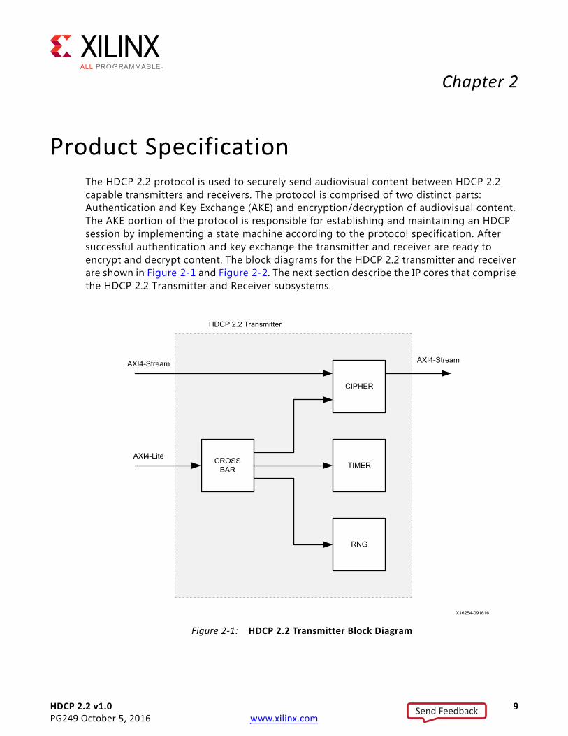
Product SpecificationThe HDCP 2.2 protocol is used to securely send audiovisual content between HDCP 2.2 capable transmitters and receivers. The protocol is comprised of two distinct parts: Authentication and Key Exchange (AKE) and encryption/decryption of audiovisual content. The AKE portion of the protocol is responsible for establishing and maintaining an HDCP session by implementing a state machine according to the protocol specification. After successful authentication and key exchange the transmitter and receiver are ready to encrypt and decrypt content. The block diagrams for the HDCP 2.2 transmitter and receiver are shown in Figure 2-1 and Figure 2-2. The next section describe the IP cores that comprise the HDCP 2.2 Transmitter and Receiver subsystems.
X-Ref Target - Figure 2-1
Figure 2-1: HDCP 2.2 Transmitter Block Diagram
CIPHER
TIMER
RNG
CROSSBAR
AXI4-Stream AXI4-Stream
AXI4-Lite
HDCP 2.2 Transmitter
Send Feedback

HDCP 2.2 v1.0 10PG249 October 5, 2016 www.xilinx.com
Chapter 2: Product Specification
IP CoresThe HDCP 2.2 transmitter and receiver are composed of the IP cores outlined in the following sections.
CipherThe cipher receives audiovisual content over its AXI4-Stream interface and is responsible for performing encryption and decryption operations. The cipher is aware of the Encryption Status Signaling (ESS) provided by the HDMI subsystem to determine when to encrypt or decrypt frames using its AES-128 block cipher.
X-Ref Target - Figure 2-2
Figure 2-2: HDCP 2.2 Receiver Block Diagram
CIPHER
TIMER
RNG
CROSSBAR
AXI4-Stream AXI4-Stream
AXI4-Lite
HDCP 2.2 Receiver
MMULT
Send Feedback

HDCP 2.2 v1.0 11PG249 October 5, 2016 www.xilinx.com
Chapter 2: Product Specification
The HDCP 2.2 Cipher is responsible for encrypting and decrypting audiovisual content using an Advanced Encryption Standard (AES) based cipher implementation with a block size of 128 bits as required by the HDCP 2.2 protocol. The Cipher is keyed based on two confidential parameters: session key (ks) and DCP global constant (lc128). The lc128 constant is issued by the DCP to HDCP 2.2 adopters while ks is a random value generated during the authentication and key exchange process. Both parameters are loaded into the cipher before the first frame is encrypted or decrypted.
For HDCP 2.2 over HDMI, the Cipher operates in counter mode where the count increments based on the frame and data word. Encryption Status Signaling (ESS) control characters transmitted over the TMDS channels carry information to signal the receiver when to decrypt incoming frames. The Cipher in the HDCP 2.2 transmitter is responsible for generating the ESS signaling, while the Cipher in the HDCP 2.2 receiver must react to the ESS signaling.
Random Number Generator (RNG)The random number generator is required for generation of true random numbers used during the authentication and key exchange protocol (that is, km, rtx, rrx, rn, ks).
During authentication and key exchange the HDCP 2.2 protocol requires generation of random numbers that are exchanged between the transmitter and receiver. While some of the random numbers are only required to be pseudo-random, secret keys such as the master key (km) and session key (ks) are required to be truly random. The HDCP 2.2 Random Number Generator (RNG) produces true random numbers through the use of a ring oscillator method where the oscillation frequency is the source of entropy and is susceptible to temperature, voltage variations, and system noise.
Montgomery Modular Multiplier (MMULT)The Montgomery modular multiplier is used only in the HDCP 2.2 receiver and is required to offload the PKCS#1 modular exponentiation process into hardware to meet the protocol timing requirements.
Exchange of the master key (km) during authentication and key exchange is performed securely using the Public Key Cryptography System (PKCS #1), which is based on the RSA algorithm. The HDCP 2.2 protocol does not place timing restrictions on the encryption of km with the public key by the transmitter. Because the specification does not specify a timing requirement for the encryption of km, plus the fact that the public key has a relatively small public exponent, makes a software implementation of the RSA Encryption Primitive (RSAEP) feasible.
On the other hand, the HDCP 2.2 protocol does place a one second timing constraint for the decryption of the master key (Ekpub (km)) using the RSA private key. Meeting the one second timing requirement in the context of an embedded application is too computationally intensive to satisfy in a software only implementation when considering
Send Feedback
HDCP 2.2 v1.0 12PG249 October 5, 2016 www.xilinx.com
Chapter 2: Product Specification
that the private exponent is a large value. As a result, the RSA Decryption Primitive (RSADP) is partially offloaded into hardware using the Montgomery Modular Multiplier (MMULT) in conjunction to the binary square and multiply method. This technique significantly reduces the time required to decrypt the master key.
TimerThis is the AXI Timer LogiCORE IP and is configured with two internal counters. One of the counters is used as a watchdog timer producing interrupts when a timeout period has expired, and the other is used to generate timestamps for logging. The watchdog timer is triggered by the software driver to track timeout periods between message transactions.
During the HDCP 2.2 authentication and key exchange process, the transmitter and receiver is required to measure message transaction time intervals using a watchdog timer. When a message transaction fails to meet the timing requirement the authentication and key exchange process is aborted. The HDCP 2.2 timer is loaded with the desired timeout value and generates an interrupt to signal to the driver that the timer has expired.
In order to provide performance data and to aid debugging, the HDCP 2.2 transmitter and receiver insert timestamps into the driver log buffer based on the HDCP 2.2 timer counter. Every event that is written into the log buffer is tagged with a relative time. The relative time along with the computed delta is printed when the log is displayed.
AXI4-Lite CrossbarThis is the AXI crossbar LogiCORE IP which allows the HDCP 2.2 to expose a single external AXI4-Lite slave interface with a contiguous address space for status and control of internal slaves by the processor.
StandardsThe Xilinx HDCP 2.2 is complaint with the HDCP 2.2 specification entitled High-bandwidth Digital Content Protection, Mapping HDCP to HDMI, Revision 2.2, issued by Digital Content Protection (DCP) LLC [Ref 12].
In addition, the Xilinx HDCP 2.2 is compliant to the changes and test vectors outlined in the Errata to HDCP 2.2 on HDMI Specification, Version 2, February 09, 2015, issued by the DCP LLC [Ref 13].
Send Feedback

HDCP 2.2 v1.0 13PG249 October 5, 2016 www.xilinx.com
Chapter 2: Product Specification
Performance and Resource UtilizationFor full details about performance and resource utilization, visit one of:
• Performance and Resource Utilization web page (transmitter)
• Performance and Resource Utilization web page (receiver)
Port DescriptionsFigure 2-3 shows the port diagram for the HDCP 2.2 transmitter and receiver. There are three interfaces used for the purpose of control/status and data flow as follows:
• AXI4-Lite Slave interface for control and status (S_AXI_CPU)
• AXI4-Stream Slave interface for data input (S_AXIS_HDCP)
• AXI4-Stream Master interface for data output (M_AXIS_HDCP)
Table 2-1 lists the system ports that are used for clocking, reset, and interrupts. The AXI4-Lite host interface and interrupt signals are synchronous to the cpu_aclk domain. The AXI4-Stream Ingress/Egress interfaces are synchronous to the hdcp_aclk domain.
X-Ref Target - Figure 2-3
Figure 2-3: HDCP Pinout
S_AXI_CPU
S_AXIS_HDCP
cpu_aclk
cpu_aresetn
hdcp_aclk
hdcp_aclken
hdcp_aresetn
M_AXIS_HDCP
cipher_irq
timer_irq
Send Feedback

HDCP 2.2 v1.0 14PG249 October 5, 2016 www.xilinx.com
Chapter 2: Product Specification
Table 2-2 lists the AXI4-Lite ports for the Host interface used for control and status.
Table 2-3 lists the AXI4-Stream ports for the HDCP Egress interface. For the HDCP 2.2 transmitter the Egress interface is where the unencrypted data comes into the HDCP 2.2 transmitter. Conversely, for the HDCP 2.2 receiver the encrypted data comes into the HDCP Egress interface.
Table 2-1: HDCP 2.2 Ports
Name Direction Descriptioncpu_aclk Input AXI4-Lite clock
cpu_aresetn Input AXI4-Lite reset, active-Low
cipher_irq OutputCipher interrupt, synchronous to cpu_aclk. This interrupt is currently unused for both transmitter and receiver and is always driven Low.
timer_irq OutputTimer interrupt, synchronous to cpu_aclk. This interrupt is currently only used by the transmitter for watchdog timer functionality, but for the receiver it is always driven Low.
hdcp_aclk Input AXI4-Stream clock
hdcp_aclken Input AXI4-Stream clock enable
hdcp_aresetn Input AXI4-Stream reset, active-Low
Table 2-2: HDCP 2.2 Host Interface
Name Direction Description
s_axi_cpu_awaddr[17:0] Input AXI4-Lite write address
s_axi_cpu_awvalid Input AXI4-Lite write address valid
s_axi_cpu_awready Output AXI4-Lite write address ready
s_axi_cpu_wdata[31:0] Input AXI4-Lite write data
s_axi_cpu_wstrb[3:0] Input AXI4-Lite write strobe
s_axi_cpu_wvalid Input AXI4-Lite write valid
s_axi_cpu_wready Output AXI4-Lite write ready
s_axi_cpu_bresp[1:0] Output AXI4-Lite write response
s_axi_cpu_bvalid Output AXI4-Lite write response valid
s_axi_cpu_bready Input AXI4-Lite write response ready
s_axi_cpu_araddr[17:0] Input AXI4-Lite read address
s_axi_cpu_arvalid Input AXI4-Lite read address valid
s_axi_cpu_arready Output AXI4-Lite read address ready
s_axi_cpu_rdata[31:0] Output AXI4-Lite read data
s_axi_cpu_rresp[1:0] Output AXI4-Lite read response
s_axi_cpu_rvalid Output AXI4-Lite read valid
s_axi_cpu_rready Input AXI4-Lite read ready
Send Feedback

HDCP 2.2 v1.0 15PG249 October 5, 2016 www.xilinx.com
Chapter 2: Product Specification
Table 2-4 lists the AXI4-Stream ports for the Ingress interface. For the HDCP 2.2 transmitter the Ingress interface is where the encrypted data goes out for transmission over the link. Conversely, for the HDCP 2.2 receiver the decrypted data goes out through the HDCP Ingress interface to the downstream device.
Table 2-3: HDCP 2.2 Egress Interface
Name Direction Description
s_axis_hdcp_tdata[95:0] Input AXI4-Stream egress data
s_axis_hdcp_tid Input AXI4-Stream egress identifier
s_axis_hdcp_tlast Input AXI4-Stream egress last
s_axis_hdcp_tready Output AXI4-Stream egress ready
s_axis_hdcp_tstrb[3:0] Input AXI4-Stream egress strobe
s_axis_hdcp_tuser[31:0] Input
AXI4-Stream egress userBits[31:28] = Keep out region indicator (debug only)Bits[27:24] = Window of opportunity indicatorBits[23:20] = EESS control signaling (lane 3)Bit[19] = Vertical sync (lane 3).Bit[18] = Horizontal sync (lane 3)Bits[17:14] = EESS control signaling (lane 2)Bits[13] = Vertical sync (lane 2)Bit[12] = Horizontal sync (lane 2)Bits[11:8] = EESS control signaling (lane 1)Bit[7] = Vertical sync (lane 1)Bit[6] = Horizontal sync (lane 1)Bits[5:2] = EESS control signaling (lane 0)Bit[1] = Vertical sync (lane 0)Bit[0] = Horizontal sync (lane 0)
s_axis_hdcp_tvalid Input AXI4-Stream egress valid
Table 2-4: HDCP 2.2 Ingress Interface
Name Direction Description
m_axis_hdcp_tdata[95:0] Output AXI4-Stream ingress data
m_axis_hdcp_tid Output AXI4-Stream ingress identifier
m_axis_hdcp_tlast Output AXI4-Stream ingress last
m_axis_hdcp_tready Input AXI4-Stream ingress ready
m_axis_hdcp_tstrb[3:0] Output AXI4-Stream ingress strobe
m_axis_hdcp_tuser[31:0] OutputAXI4-Stream ingress userSame bit fields as port s_axis_hdcp_tuser.
m_axis_hdcp_tvalid Output AXI4-Stream ingress valid
Send Feedback
HDCP 2.2 v1.0 16PG249 October 5, 2016 www.xilinx.com
Chapter 3
Designing with the IPThis chapter includes guidelines and additional information to facilitate designing with the IP.
Because the HDCP 2.2 is provided as part of a subsystem, there is no direct interface to the HDCP 2.2; instead the HDMI transmitter/receiver subsystem automatically configures itself to work with HDCP 2.2. See the HDMI product guides (HDMI 1.4/2.0 Transmitter Subsystem v1.0 Product Guide (PG235) [Ref 1] and HDMI 1.4/2.0 Receiver Subsystem v1.0 Product Guide (PG236) [Ref 2]) to understand how to build systems with the HDMI transmitter/receiver subsystems.
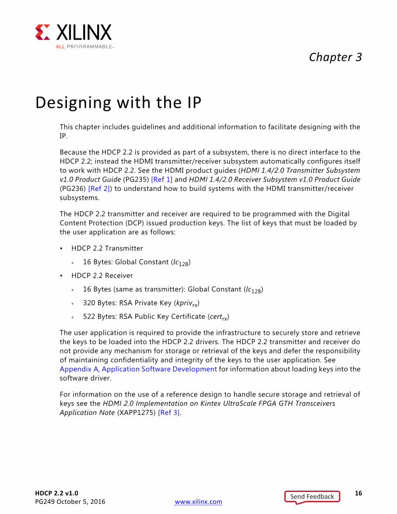
The HDCP 2.2 transmitter and receiver are required to be programmed with the Digital Content Protection (DCP) issued production keys. The list of keys that must be loaded by the user application are as follows:
• HDCP 2.2 Transmitter
° 16 Bytes: Global Constant (lc128)
• HDCP 2.2 Receiver
° 16 Bytes (same as transmitter): Global Constant (lc128)
° 320 Bytes: RSA Private Key (kprivrx)
° 522 Bytes: RSA Public Key Certificate (certrx)
The user application is required to provide the infrastructure to securely store and retrieve the keys to be loaded into the HDCP 2.2 drivers. The HDCP 2.2 transmitter and receiver do not provide any mechanism for storage or retrieval of the keys and defer the responsibility of maintaining confidentiality and integrity of the keys to the user application. See Appendix A, Application Software Development for information about loading keys into the software driver.
For information on the use of a reference design to handle secure storage and retrieval of keys see the HDMI 2.0 Implementation on Kintex UltraScale FPGA GTH Transceivers Application Note (XAPP1275) [Ref 3].
Send Feedback

HDCP 2.2 v1.0 17PG249 October 5, 2016 www.xilinx.com
Chapter 3: Designing with the IP
General Design GuidelinesHDCP 2.2 is included as part of the HDMI subsystem, thus hardware integration of the IP is handled by the subsystem. The subsystem is responsible for instantiating the HDCP 2.2 IP and interfacing it with the HDMI IP. Since the hardware is abstracted into subsystems, much of the integration of HDCP 2.2 is responsible with using the software driver APIs to load the production keys and bind callbacks executed during the state machine execution. This section describes the software integration concepts that are important to understand in order to initialize and execute the HDCP 2.2 state machines.
Transmitter KeysThe HDCP 2.2 transmitter cipher is required to be loaded with the Global Constant (lc128). All HDCP 2.2 devices use this global constant as a parameter to key the AES-128 cipher. This is a 128-bit value that is provided only to HDCP adopters and is formatted in big endian byte order. The confidentiality and integrity of this key must be maintained by the user application. The HDCP 2.2 driver provides the facility to load this key during the driver initialization process. This key must be loaded prior to executing the HDCP 2.2 transmitter state machine. If the key is not loaded properly or an incorrect key is loaded the authentication and key exchange process will complete successfully, but the transmitter cipher will produce incorrect cipher words.
Receiver KeysThe HDCP 2.2 Receiver cipher is required to be loaded with the same lc128 Global Constant described in the previous section. Besides this key there are two other keys that are unique to every individual HDCP 2.2 Receiver device namely, the Device Private Key (kprivrx) and Device Public Key Certificate (certrx).
The DCP provides the Device Private Key, in a format convenient for performing modular exponentiation using the Chinese Remainder Theorem (CRT) in order to reduce computation time. The Private Key is a 320-Byte value comprised of a quintuple (p, q, dP, dQ, qInv) provided only to HDCP adopters and is formatted in big endian byte order. The confidentiality and integrity of this key must be maintained by the user application. The HDCP 2.2 driver provides the facility to load this key during the driver initialization process. This key must be loaded prior to executing the HDCP 2.2 transmitter state machine. If the key is not loaded properly or an incorrect key is loaded the authentication and key exchange process will fail during the exchange of the RSA encrypted master key (km) in the AKE_No_Stored_km message.
The Device Public Key Certificate contains the unique receiver ID, Receiver Public Key, and the DCP signature used for verification of the certificate. The Public Key Certificate is a 522-Byte value formatted in big endian byte order. The user application must maintain the integrity of the Public Key Certificate, but confidentiality is not required. The HDCP 2.2
Send Feedback

HDCP 2.2 v1.0 18PG249 October 5, 2016 www.xilinx.com
Chapter 3: Designing with the IP
driver provides the facility to load this key during the driver initialization process. The key is must be loaded prior to executing the HDCP 2.2 transmitter state machine. If the key is not loaded properly or an incorrect key is loaded the authentication and key exchange process will fail during the exchange of the Public Key Certificate in the AKE_Send_Cert message because the signature verification fails by the transmitter.
Service Renewability MessagesThe HDCP 2.2 transmitters are required to perform revocation checks in order to determine if downstream receivers are blacklisted or revoked by the DCP, thus forcing authentication to be aborted. The SRM contains a list of receiver IDs that have been identified by the DCP to be compromised and that should be revoked by the HDCP 2.2 transmitter. The SRM header defines how many receiver IDs are contained in the SRM. The user application is responsible for the maintenance and integrity of the SRM. The HDCP 2.2 driver provides the facility to load the complete SRM during the driver initialization process. The SRM must be loaded prior to executing the HDCP 2.2 transmitter state machine. If the SRM is not loaded properly, an incorrect SRM is loaded, or a receiver ID matches the revocation list, the transmitter fails and aborts the authentication protocol.
State Machine PerformanceThe HDCP 2.2 state machines are executed by calling a poll function periodically by the user application. The performance of the state machine is dependent upon the frequency that the poll function is called. It is important not to starve the poll for any given interface which could lead to degraded performance and potentially cause authentication failure by missing one of the deadlines defined in the specification. The HDCP 2.2 transmitter and receiver IP drivers provide a log buffer, which can be used to assess the protocol behavior and performance.
During authentication, the HDCP 2.2 specification defines real time deadlines for message exchange, which are enforced by either the transmitter or receiver. The strictest deadline defined by the protocol is the exchange of the LC_Send_L_prime message, which should be received by the transmitter within 20 ms after the last byte of the LC_Init message is sent. The user application should ensure that the HDCP 2.2 poll function is called more often than once every 20 ms to avoid starving state machine execution during authentication. Applications which have multiple HDCP 2.2 upstream or downstream interfaces should ensure that execution of the poll functions are scheduled in such a way to avoid starvation between interfaces.
Transmitter and Receiver OperationAn HDCP 2.2 top-level transmitter is able to authenticate with the following class of devices:
• HDCP 2.2 endpoint receiver
• HDCP 2.2 repeater upstream interface
Send Feedback

HDCP 2.2 v1.0 19PG249 October 5, 2016 www.xilinx.com
Chapter 3: Designing with the IP
Depending upon which class of device that the transmitter is connected, the authentication state machine executes slightly differently. Specifically, authentication with a repeater will require exchange of topology information and stream management information, which is not required when authenticating with an endpoint receiver. The HDCP 2.2 transmitter driver allows callback functions to be registered, which are executed at various transitions of the state machine. The transmitter callback events are described in Appendix A, Application Software Development, and are summarized in Table 3-1.
The top-level HDCP 2.2 transmitter is responsible for determining when to start transmission of high value content. The transmitter can enable encryption only after the state machine has transitioned to the authenticated state; therefore, when the state machine is not authenticated, only low value content should be sent downstream. The transmitter can use the authenticated callback to determine when to start transmission of high value content. Note that the transmitter is allowed to send low value content either encrypted or unencrypted, but high value content should always be encrypted. Conversely, the transmitter can use the Unauthenticated callback to determine when to halt transmission of high value content.
An HDCP 2.2 endpoint receiver is able to authenticate with the following class of devices:
• HDCP 2.2 top-level transmitter
• HDCP 2.2 repeater downstream interface
Unlike a transmitter, the receiver state machine execution is identical whether it authenticates with a top level transmitter or repeater interface. The HDCP 2.2 Receiver driver callback events are described in Appendix A, Application Software Development, and are summarized in Table 3-2.
Note: Some of the callbacks are only available when the receiver is operating as a repeater upstream interface.
Table 3-1: Transmitter Callback Events
Callback Event Description
Authenticated Executed when the state machine transitions to the authenticated state.
Unauthenticated Executed when the state machine transitions from any state back to the unauthenticated state.
Topology Available Executed when topology information is available for upstream propagation.
Table 3-2: Receiver Callback Events
Callback Event Description
Authenticated Executed when the state machine transitions to the authenticated state.
Unauthenticated Executed when the state machine transitions to the unauthenticated state.
Authentication Request Executed when an authentication request is received from an upstream transmitter (AKE_Init).
Send Feedback

HDCP 2.2 v1.0 20PG249 October 5, 2016 www.xilinx.com
Chapter 3: Designing with the IP
The HDCP 2.2 Receiver is ready to decrypt incoming content immediately after it has transitioned to the authenticated state. Since the transmitter decides when to encrypt content, the receiver must be ready to decrypt any time after the state machine has transitioned to the authenticated state, which is handled automatically by the HDCP 2.2 IP. When the Receiver is used in non-repeater mode as part of a repeater design, as shown in Figure 3-1, it is important to note that the upstream and downstream interface are disjoint. In other words, the authentication protocol for the upstream interface and downstream interface are independent such that the top-level transmitter (Tx1) is not aware of the authentication status of the downstream receiver (Rx1).
In the disjoint repeater topology, it is the responsibility of the transmitter on the downstream interface (Tx2) to block transmission of the protected content when it is not authenticated. It can do this by sending low value content, such as a blue screen over the downstream interface. The HDCP 2.2 Transmitter cipher provides the ability to block
Encryption UpdateExecuted when the encryption status changes from unencrypted to encrypted or vice versa if the receiver is in the authenticated state. Based on a 1 second timer interrupt.
Topology Update Executed when the state machine is waiting for the topology information to propagate upstream. Only available in repeater mode.
Stream Management RequestExecuted when a content stream management information message is received (RepeaterAuth_Stream_Manage). Only available in repeater mode.
X-Ref Target - Figure 3-1
Figure 3-1: Disjoint Repeater Topology with Single Downstream Interface
Table 3-2: Receiver Callback Events (Cont’d)
Callback Event Description
Send Feedback
HDCP 2.2 v1.0 21PG249 October 5, 2016 www.xilinx.com
Chapter 3: Designing with the IP
content by producing a blank output. The receiver Authenticated and Unauthenticated callback events can be used to enable blocking of content downstream based on the encryption status of upstream interface. The receiver driver sets a one second periodic timer interrupt once the state machine has transitioned to the authenticated state. The timer interrupt is used to check the encryption status of the incoming frame. During this time if the encryption status changes from unencrypted to encrypted, or vice versa, the Encryption Update callback event is executed. In the encryption update callback, if the upstream interface is authenticated and encrypted, but the downstream interface is not authenticated, then the content should be blocked.
It is also important to consider when encryption should be enabled on the downstream interface for the disjoint repeater topology. There are two options for enabling encryption as follows:
• Option 1: Enable encryption immediately after the downstream interface has transitioned to the authenticated state
• Option 2: Enable encryption after the downstream interface has transitioned to the authenticated state and the upstream interface has begun receiving encrypted frames.
Option 1 is the preferred method because it avoids the possibility of sending protected content downstream without enabling encryption. The reason being that the upstream receiver (Rx2) can detect that the incoming frame is encrypted with a granularity of one second based on the encryption update callback event. It is possible for the receiver to miss an encrypted frame that occurs in between the one second interval. In addition, it is possible for a malicious source to encrypt every other frame or some other pattern which could circumvent the receiver from detecting that the incoming frame is encrypted.
RECOMMENDED: For the various reasons described earlier, it is recommended that you use a true repeater configuration rather than a disjoint repeater.
The next section describes the operation of the transmitter and receiver in repeater mode.
Repeater and Converter OperationHDCP 2.2 repeaters have one upstream interface and one or more downstream interfaces as shown in Figure 3-2. Repeaters can be cascaded with a maximum DEPTH of 4, and maximum DEVICE_COUNT of 31. The HDCP 2.2 Transmitter and Receiver IP can be set in repeater mode at runtime by the user application. Enabling the repeater mode changes the behavior of the transmitter and receiver authentication state machine from operating as a transmitter or receiver to a repeater downstream or upstream interface respectively.
Send Feedback

HDCP 2.2 v1.0 22PG249 October 5, 2016 www.xilinx.com
Chapter 3: Designing with the IP
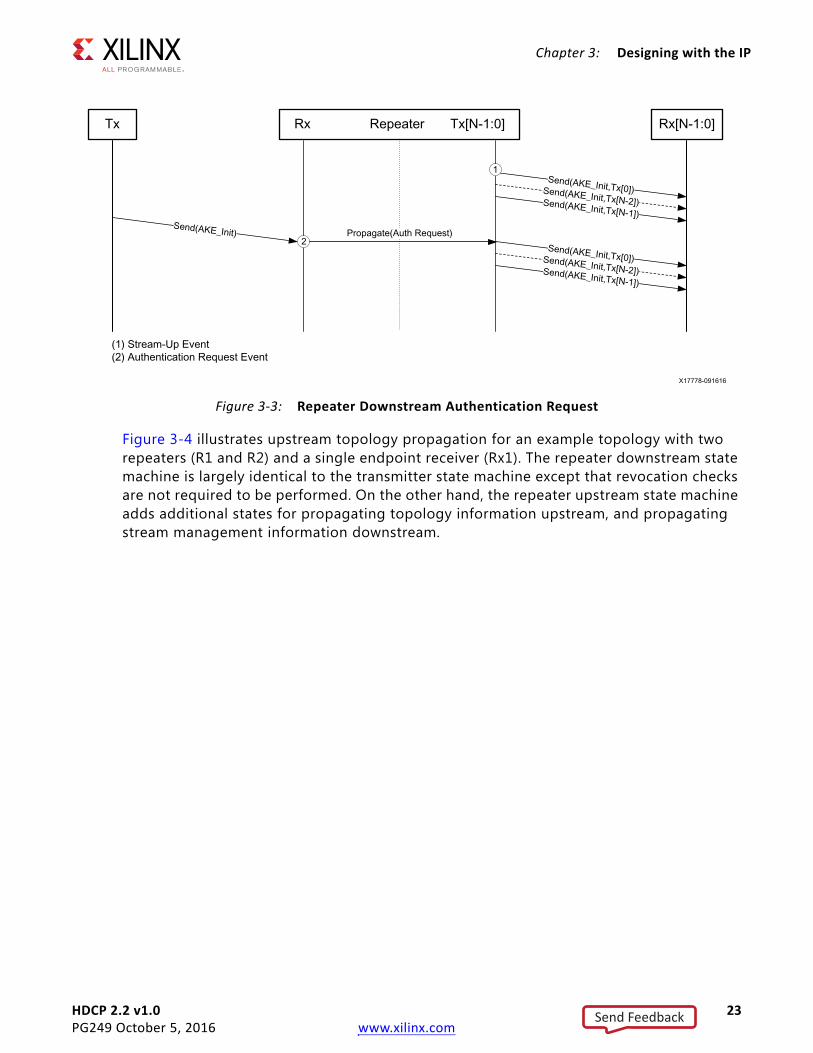
The callback events defined in the previous section are the same ones used while in repeater mode. Figure 3-3 shows how downstream authentication requests can be triggered by the user application. The first method is to immediately trigger authentication after the downstream interface is ready to transmit content denoted by the Stream-Up event. The Stream-Up event is produced by the HDMI Transmitter. The second method is to propagate the authentication request using the HDCP 2.2 Authentication Request event callback. In the second method, authentication should be triggered only for downstream interface that are not already in the authenticated state.
X-Ref Target - Figure 3-2
Figure 3-2: Repeater with Single Downstream Interface
Send Feedback
HDCP 2.2 v1.0 23PG249 October 5, 2016 www.xilinx.com
Chapter 3: Designing with the IP
Figure 3-4 illustrates upstream topology propagation for an example topology with two repeaters (R1 and R2) and a single endpoint receiver (Rx1). The repeater downstream state machine is largely identical to the transmitter state machine except that revocation checks are not required to be performed. On the other hand, the repeater upstream state machine adds additional states for propagating topology information upstream, and propagating stream management information downstream.
X-Ref Target - Figure 3-3
Figure 3-3: Repeater Downstream Authentication Request
Send Feedback

HDCP 2.2 v1.0 24PG249 October 5, 2016 www.xilinx.com
Chapter 3: Designing with the IP
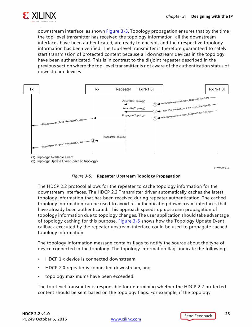
Topology information is propagated upstream from the lowest level of the repeater topology to the top-level transmitter. Each of the repeaters in the topology will send their topology information upstream after its downstream interfaces have been authenticated and the topology information has been verified. The HDCP 2.2 Transmitter driver provides the Topology Available event callback as a means to assemble the topology for each
X-Ref Target - Figure 3-4
Figure 3-4: Repeater Upstream Topology Propagation, DEPTH=2, DEVICE_COUNT=2
Send Feedback
HDCP 2.2 v1.0 25PG249 October 5, 2016 www.xilinx.com
Chapter 3: Designing with the IP
downstream interface, as shown Figure 3-5. Topology propagation ensures that by the time the top-level transmitter has received the topology information, all the downstream interfaces have been authenticated, are ready to encrypt, and their respective topology information has been verified. The top-level transmitter is therefore guaranteed to safely start transmission of protected content because all downstream devices in the topology have been authenticated. This is in contrast to the disjoint repeater described in the previous section where the top-level transmitter is not aware of the authentication status of downstream devices.
The HDCP 2.2 protocol allows for the repeater to cache topology information for the downstream interfaces. The HDCP 2.2 Transmitter driver automatically caches the latest topology information that has been received during repeater authentication. The cached topology information can be used to avoid re-authenticating downstream interfaces that have already been authenticated. This approach speeds up upstream propagation of topology information due to topology changes. The user application should take advantage of topology caching for this purpose. Figure 3-5 shows how the Topology Update Event callback executed by the repeater upstream interface could be used to propagate cached topology information.
The topology information message contains flags to notify the source about the type of device connected in the topology. The topology information flags indicate the following:
• HDCP 1.x device is connected downstream,
• HDCP 2.0 repeater is connected downstream, and
• topology maximums have been exceeded.
The top-level transmitter is responsible for determining whether the HDCP 2.2 protected content should be sent based on the topology flags. For example, if the topology
X-Ref Target - Figure 3-5
Figure 3-5: Repeater Upstream Topology Propagation
Send Feedback

HDCP 2.2 v1.0 26PG249 October 5, 2016 www.xilinx.com
Chapter 3: Designing with the IP
information indicates that an HDCP 1.x device is present downstream, the top-level transmitter may decide to avoid sending the protected content.
Stream management information is propagated downstream originating from the top-level transmitter. The top-level transmitter must decide whether the content is of Type 0 or Type 1. Type 0 content can be sent to all HDCP devices, while Type 1 content can be transmitted only to HDCP 2.2 devices. The HDCP 2.2 Receiver driver executes the Stream Management Request event callback when a stream management request is received as shown in the second event in Figure 3-6. When the callback is executed, the user application can extract the stream type to determine if stream should be blocked over a downstream interface. When converting from HDCP 1.4 to HDCP 2.2, the transmitter will not send the Stream Management Information; therefore, the stream type is set to zero for all downstream interfaces after the Authentication Request Event.
The HDCP 2.2 protocol supports conversion from HDCP 2.2 to HDCP 1.x, and vice versa. The HDMI Subsystem can be customized to support any set of HDCP protocols including enabling both HDCP 1.x and 2.2. It is important to consider when to block content to a device connected to a repeater downstream interface based on the supported protocol. Table 3-3 lists the repeater configurations with connected devices and when the downstream interface should block content. When the receiver does not support at least one of the protocols supported by the repeater, the downstream interface is blocked.
Note: The HDCP 2.2 IP does not support the HDCP 1.x protocol. In order to support protocol conversion, the HDCP 1.x must also be included in the subsystem.
X-Ref Target - Figure 3-6
Figure 3-6: Repeater Downstream Content Stream Management Propagation
Send Feedback

HDCP 2.2 v1.0 27PG249 October 5, 2016 www.xilinx.com
Chapter 3: Designing with the IP
If there are no HDCP capable devices connected to the repeater downstream interface, repeater can do one of the following:
• Option 1: De-assert HPD on the repeater upstream interface.
• Option 2: Disable repeater support on the upstream interface and do not send protected content downstream.
Option 1 is the simplest approach, but does not allow any content downstream, even unprotected content. After an HDCP capable device is connected, HPD is asserted and the repeater authentication is allowed to proceed. Option 2 has the added benefit of allowing unprotected content downstream, but requires effort in blocking content if content protection is enabled on the upstream interface. Once an HDCP capable device is connected the upstream interface can change itself back to repeater mode and toggle the HPD for at least 100ms to notify the upstream transmitter to re-authenticate. Depending upon the requirement, users must decide which option to implement for their application.
Automatic Protocol SwitchingThe HDMI Receiver Subsystem implements the ability to perform automatic HDCP protocol switching. The HDMI Receiver changes the active protocol based on what address range the transmitter is trying to access. HDCP 1.4 occupies the I2C address range from 0x00 to 0x44, while HDCP 2.2 occupies the address range from 0x50 to 0x81. The protocol states that an HDCP 2.2 transmitter is required to successfully read the HDCP 2 version register before initiating authentication. When the HDMI Receiver detects the first read of the register, it automatically sets HDCP 2.2 as the active protocol. Similarly, the HDCP 1.x transmitter is required to successfully read an HDCP 1.x register before initiating authentication. The HDMI Receiver automatically sets HDCP 1.x as the active protocol after successful read of the HDCP 1.x register.
Table 3-3: Repeater Downstream Protocol Blocking
Repeater Supported Protocols Receiver Supported Protocols Block?
HDCP 2.2 HDCP 2.2 No
HDCP 2.2 HDCP 1.x Yes
HDCP 2.2 None Yes
HDCP 1.x HDCP 1.x No
HDCP 1.x HDCP 2.2 Yes
HDCP 1.x None Yes
HDCP 1.x and HDCP 2.2 HDCP 1.x No
HDCP 1.x and HDCP 2.2 HDCP 2.2 No
HDCP 1.x and HDCP 2.2 HDCP 1.x and HDCP 2.2 No
HDCP 1.4/2.2 None Yes
Send Feedback

HDCP 2.2 v1.0 28PG249 October 5, 2016 www.xilinx.com
Chapter 3: Designing with the IP
Note: The HDCP 2.2 IP does not support the HDCP 1.x protocol. In order to support Automatic Protocol Switching, the HDCP 1.x must also be included in the subsystem.
ClockingThe HDCP 2.2 IP has two clock domains:
• cpu_aclk: This is the host processor clock domain, which is used for control and status. This clock domain is typically a fixed frequency. The following IP cores in HDCP 2.2 operate solely on this clock domain: Random Number Generator, Montgomery Modular Multiplier, and Timer.
• hdcp_aclk: This is the audiovisual data clock domain, which is used to clock the Cipher data path. The frequency of this clock domain can vary depending upon the HDMI link clock frequency.
ResetsThe HDCP 2.2 blocks have two resets:
• cpu_aresetn: This reset input is active-Low and synchronous to the cpu_aclk domain.
• hdcp_aresetn: This reset input is active-Low and synchronous to the hdcp_aclk domain.
Send Feedback

HDCP 2.2 v1.0 29PG249 October 5, 2016 www.xilinx.com
Chapter 4
Design Flow StepsThis chapter describes customizing and generating the IPs, constraining the IPs, and the simulation, synthesis and implementation steps that are specific to these IPs. More detailed information about the standard Vivado® design flows and the IP integrator can be found in the following Vivado Design Suite user guides:
• Vivado Design Suite User Guide: Designing IP Subsystems using IP Integrator (UG994) [Ref 4]
• Vivado Design Suite User Guide: Designing with IP (UG896) [Ref 5]
• Vivado Design Suite User Guide: Getting Started (UG910) [Ref 6]
• Vivado Design Suite User Guide: Logic Simulation (UG900) [Ref 7]
Customizing and Generating the IPThis section includes information about using Xilinx tools to customize and generate the IP in the Vivado Design Suite.
If you are customizing and generating the IP in the Vivado IP integrator, see the Vivado Design Suite User Guide: Designing IP Subsystems using IP Integrator (UG994) [Ref 4] for detailed information. IP integrator might auto-compute certain configuration values when validating or generating the design. To check whether the values do change, see the description of the parameter in this chapter. To view the parameter value, run the validate_bd_design command in the Tcl console.
You can customize the IP for use in your design by specifying values for the various parameters associated with the IP using the following steps:
1. Select the HDMI Transmitter or Receiver Subsystem from the Vivado IP catalog. The HDCP 2.2 IP is automatically generated as part of the HDMI Subsystem.
2. Double-click the selected IP or select the Customize IP command from the toolbar or right-click menu.
For details, see the Vivado Design Suite User Guide: Designing with IP (UG896) [Ref 5] and the Vivado Design Suite User Guide: Getting Started (UG910) [Ref 6].
Note: Figures in this chapter are illustrations of the Vivado Integrated Design Environment (IDE). The layout depicted here might vary from the current version.
Send Feedback

HDCP 2.2 v1.0 30PG249 October 5, 2016 www.xilinx.com
Chapter 4: Design Flow Steps
The HDMI Transmitter Subsystem IP customization screen is shown in Figure 4-1. Enable the checkbox to include the HDCP 2.2 transmitter IP in the subsystem.
The HDMI Receiver Subsystem IP customization GUI is shown in Figure 4-2. Enable the checkbox to include the HDCP 2.2 receiver in the subsystem.
X-Ref Target - Figure 4-1
Figure 4-1: HDMI Transmitter Subsystem Customization for HDCP 2.2
X-Ref Target - Figure 4-2
Figure 4-2: HDMI Receiver Subsystem Customization for HDCP 2.2
Send Feedback

HDCP 2.2 v1.0 31PG249 October 5, 2016 www.xilinx.com
Chapter 4: Design Flow Steps
Constraining the IPThis section contains information about constraining the IP in the Vivado Design Suite.
Required ConstraintsThis section is not applicable for this IP.
Device, Package, and Speed Grade SelectionsThis section is not applicable for this IP.
Clock FrequenciesThis section is not applicable for this IP.
Clock ManagementThis section is not applicable for this IP.
Clock PlacementThis section is not applicable for this IP.
BankingThis section is not applicable for this IP.
Transceiver PlacementThis section is not applicable for this IP.
I/O Standard and PlacementThis section is not applicable for this IP.
Send Feedback

HDCP 2.2 v1.0 32PG249 October 5, 2016 www.xilinx.com
Chapter 4: Design Flow Steps
SimulationFor comprehensive information about Vivado simulation components, as well as information about using supported third-party tools, see the Vivado Design Suite User Guide: Logic Simulation (UG900) [Ref 7].
IMPORTANT: For IPs targeting 7 series or Zynq®-7000 devices, UNIFAST libraries are not supported. Xilinx IP is tested and qualified with UNISIM libraries only.
Synthesis and ImplementationFor details about synthesis and implementation, see the Vivado Design Suite User Guide: Designing with IP (UG896) [Ref 5].
Send Feedback

HDCP 2.2 v1.0 33PG249 October 5, 2016 www.xilinx.com
Appendix A
Application Software DevelopmentHDCP 2.2 has a transmitter and receiver driver with the following hierarchy:
• HDCP 2.2 transmitter driver (xhdcp22_tx.h)
° HDCP 2.2 Cipher Driver (xhdcp22_cipher.h)
° HDCP 2.2 Random Number Generator Driver (xhdcp22_rng.h)
° HDCP 2.2 Common Utilities (xhdcp22_common.h)
° AXI Timer Driver (xtmrctr.h)
• HDCP 2.2 receiver (hdcp22_rx)
° HDCP 2.2 Cipher Driver (xhdcp22_cipher.h)
° HDCP 2.2 Montgomery Modular Multiplier Driver (xhdcp22_mmult.h)
° HDCP 2.2 Random Number Generator Driver (xhdcp22_rng.h)
° HDCP 2.2 Common Utilities (xhdcp22_common.h)
° AXI Timer Driver (xtmrctr.h)
The HDCP 2.2 drivers are responsible for implementing the authentication protocol state machine including, authentication, pairing, locality check, session key exchange, link integrity check, topology information propagation, and stream management information propagation. The drivers implement the majority of the cryptographic functions required by the authentication protocol, except for RSA decryption which is offloaded by the Montgomery Multiplier into hardware to meet performance requirements.
Device DriversThe subsequent sections describe the architecture of the HDCP 2.2 transmitter and receiver drivers along with key APIs used for initializing and running the driver. This section is presented for reference only and is not required to be used by user applications using HDCP 2.2 with HDMI because the HDMI drivers wrap around the HDCP 2.2 drivers, thus providing a higher layer of abstraction for user applications. Nonetheless, this information may be useful for conceptual understanding and debugging of the drivers. See the HDMI 1.4/2.0 Transmitter Subsystem v1.0 Product Guide (PG235) [Ref 1] and HDMI 1.4/2.0 Receiver
Send Feedback

HDCP 2.2 v1.0 34PG249 October 5, 2016 www.xilinx.com
Appendix A: Application Software Development
Subsystem v1.0 Product Guide (PG236) [Ref 2] for more information about the higher level HDCP wrapper API.
The drivers implement a state machine to handle the HDCP 2.2 authentication protocol. In order to facilitate integration and debugging, the names of the individual states are aligned with those defined within the specifications wherever possible. The state machine makes use of a simple operating system independent scheduler. The client application software regularly calls a non-blocking poll function in order to ensure servicing of messages and events. The relation between the HDCP 2.2 transmitter and HDCP 2.2 receiver is master and slave respectively, meaning that the transmitter is responsible for initiating authentication while the receiver is waiting to react.
Note that byte arrays used to store octet strings for HDCP 2.2 authentication are defined in big endian byte order throughout the driver.
HDCP 2.2 Transmitter Driver OverviewThe HDCP 2.2 transmitter acts as the master in the authentication protocol. The transmitter is allowed to initiate authentication with a receiver at any time after the HDCP_HPD event has occurred and the receiver is HDCP 2.2-capable. The HDCP 2.2 driver does not decide whether or not encryption is to be enabled after successful authentication; instead, the user application software is responsible for enabling encryption for the cipher and is also responsible for disabling encryption. Anytime authentication is re-initiated the cipher counters are reset for synchronization with the receiver.
The HDCP 2.2 specification requires that the transmitter perform a timeout check on most of the response messages from the receiver. For this timeout check, the HDCP 2.2 transmitter driver uses a hardware timer. The timer is initialized by the HDCP 2.2 transmitter driver at the start of message transactions. When the timer expires an interrupt event is generated by the timer and serviced by an interrupt service routine to signal to the HDCP 2.2 transmitter driver that a timeout occurred.
The HDCP 2.2 transmitter driver provides a function to set callbacks with the HDMI transmitter driver for DDC message write and read transactions. The HDMI transmitter provides the physical DDC interface and receives read/write commands from the HDCP 2.2 transmitter driver for transmission over the I2C interface.
HDCP 2.2 Transmitter Driver IntegrationThis section describes the steps required to initialize and run the HDCP 2.2 transmitter driver. The higher level software, such as the HDMI transmitter subsystem driver, should call the functions roughly in the order specified to ensure that the driver instance is initialized:
1. Initialize the HDCP 2.2 transmitter driver instance:
° XHdcp22Tx_LookupConfig
° XHdcp22Tx_CfgInitialize
Send Feedback

HDCP 2.2 v1.0 35PG249 October 5, 2016 www.xilinx.com
Appendix A: Application Software Development
2. Connect the system interrupt controller with the timer interrupt for the HDCP 2.2 transmitter. The timer is required for guarding response times of an attached HDCP 2.2 receiver and registration of time stamps in logging. The function returns the timer instance located in the HDCP 2.2 transmitter subsystem:
° XHdcp22Tx_GetTimer
3. Set callbacks for the DDC read and write handlers:
° XHdcp22Tx_SetCallbacks
4. Load DCP global constant into the cipher:
° XHdcp22Tx_LoadLc128
5. Load SRM table into the driver.
° XHdcp22Tx_LoadRevocationTable.
6. Set the polling value to tell the state machine if and when it should poll for messages from the receiver, or wait for the allowed timeout to pass before checking if an expected message has arrived. The value to be used is 0 if no polling is needed. All other integer values determine the moment polling should start. This can be calculated with 100-(100/value)%. With a value of 1, polling starts immediately. For example with a value 3, polling starts if 66% of the timeout has elapsed. A default value of 4 (75%) is set.
° XHdcp22Tx_SetMessagePollingValue
7. Set the repeater mode
° XHdcp22Tx_SetRepeater
8. Reset and enable the internal state machine.
° XHdcp22Tx_Reset
° XHdcp22Tx_Enable
9. This function is called to initiate authentication with a receiver. The user should start authentication only after a Hot Plug Detect (HPD) event from the receiver.
° XHdcp22Tx_Authenticate
10. For proper operation of the internal state machine of the HDCP 2.2 transmitter, a poll function must be called on a regular basis. The call to this function can be inserted in the main loop of the user application and should execute anytime HDCP 2.2 is enabled. The return value of the poll function can be used to detect the current authenticated state. After successful authentication, polling must be continued to detect a re-authentication request from the attached HDCP 2.2 receiver.
° XHdcp22Tx_Poll
11. The status of authentication can be checked using the following functions:
° XHdcp22Tx_IsInprogress
° XHdcp22Tx_IsAuthenticated
Send Feedback

HDCP 2.2 v1.0 36PG249 October 5, 2016 www.xilinx.com
Appendix A: Application Software Development
12. Encryption can be enabled or disabled any time after successful authentication. The HDCP 2.2 transmitter initializes the cipher with the session key, but does not enable or disable encryption. Enabling encryption is the responsibility of the user application. Note that enabling encryption is only possible if the attached HDCP 2.2 receiver is successfully authenticated. The following functions are used to enable or disable encryption:
° XHdcp22Tx_EnableEncryption
° XHdcp22Tx_DisableEncryption
13. Get the repeater topology information:
° XHdcp22Tx_GetTopologyField
° XHdcp22Tx_GetTopoogyReceiverIdList
HDCP 2.2 Transmitter Callback EventsThe HDCP 2.2 transmitter driver provides callback functions which you can be registered to perform tasks during important state machine transitions or events. These callbacks are essential for implementing repeater topology and stream management propagation. The list of callbacks are as follows:
• XHDCP22_TX_HANDLER_AUTHENTICATED
Executed when the state machine transitions to the authenticated state.
• XHDCP22_TX_HANDLER_UNAUTHENTICATED
Executed when the state machine transitions from any state to the unauthenticated state.
• XHDCP22_TX_HANDLER_DOWNSTREAM_TOPOLOGY_AVAILABLE
Executed when the state machine detects that the topology information is available from the downstream device. When the downstream device is an endpoint receiver, the topology information contains only a single device. If the downstream device is a repeater, the topology information can contain up to 31 devices. The information for the topology can be extracted using the functions: XHdcp22Tx_GetTopologyField and XHdcp22Tx_GetTopologyReceiverIdList.
HDCP 2.2 Transmitter Interrupts and PerformanceThe HDCP 2.2 transmitter driver is responsible for handling interrupts generated by the subsystem. The list of interrupt sources and associated events are as follows:
1. HDCP 2.2 Timer Interrupt
° Timer0 Event: Unused, reserved for future use.
Send Feedback

HDCP 2.2 v1.0 37PG249 October 5, 2016 www.xilinx.com
Appendix A: Application Software Development
° Timer1 Event: Indicates that the count down timer has expired. This event is used to determine protocol timeouts.
2. HDCP 2.2 Cipher Interrupt
° This interrupt is currently unused and is reserved for future use.
The HDCP 2.2 transmitter is responsible for measuring and reacting to message timeout intervals. In order to understand the detailed timeout requirements for various states of the HDCP 2.2 protocol, refer to High-bandwidth Digital Content Protection System—Mapping HDCP to HDMI Revision 2.2 [Ref 12]. Because the HDCP 2.2 transmitter state machine is run using the XHdcp22Tx_Poll function, it is important to ensure that this function is given adequate CPU runtime, especially during authentication attempts. If the poll function is starved during authentication, it is possible that authentication will fail due to protocol timing violations detected by the transmitter. Protocol timing performance can be checked based on the timestamps inserted into the log buffer as described in HDCP 2.2 Driver Logging. The HDCP 2.2 protocol places the most stringent timing requirement on the locality check, which has a message turnaround time of 20 ms by the receiver.
HDCP 2.2 Receiver Driver OverviewThe HDCP 2.2 receiver acts as the slave in the authentication protocol and waits for the transmitter to initiate authentication. The receiver driver sets the HDCP 2.2-capable bit when the driver is initialized signaling to the transmitter that it is allowed to initiate HDCP 2.2 transactions.
The HDCP 2.2 receiver defers the responsibility of tracking timing delays between different phases of the authentication protocol to the transmitter. As such, the HDCP 2.2 receiver does not preemptively timeout during the authentication protocol and instead relies on the transmitter to detect anomalies and re-initiate authentication. As an exception, the receiver driver checks that the RepeaterAuth_Send_Ack message is available in less than two seconds after the READY bit in the RxStatus register has been asserted. This is the only time that the state machine preemptively fails authentication. If unexpected messages are received or error conditions are detected during authentication, the HDCP 2.2 receiver clears message buffers and gracefully resets itself to the unauthenticated state. Any time an authentication initialization message is received, the receiver clears all state information from previous authentication attempts.
An RSA private key is required to perform authentication in order to decrypt the master key. The HDCP 2.2 receiver provides a function to load the private key pointer and DCP global constant into the driver, which gets programmed into the cipher during authentication and key exchange. Key management, or the process of storing and retrieving keys, is beyond the scope of the HDCP 2.2 receiver driver and is the responsibility of the user application. The user application should ensure that secret keys are not compromised and remain confidential per the HDCP 2.2 specification.
Other than loading the secret keys, the HDCP 2.2 driver also provides an API to load the public certificate, which is sent as part of the send certificate (AKE_Send_Cert) message. The
Send Feedback

HDCP 2.2 v1.0 38PG249 October 5, 2016 www.xilinx.com
Appendix A: Application Software Development
public key certificate is unique for each receiver device and contains a signature generated by the DCP. The public certificate is not required to be confidential and is provided to the transmitter on every authentication request.
The cryptographic functions required during receiver authentication protocol are almost entirely implemented in software with the exception of RSA decryption used to decrypt the master key. RSA decryption performs a modular exponentiation process, which is computationally intensive due to the size of the private exponent; therefore, the Montgomery Modular Multiplication algorithm runs in hardware to meet the timing requirements.
The HDCP 2.2 receiver driver provides a function to set callbacks with the HDMI receiver driver for DDC message write and read transactions. The HDMI receiver provides the physical DDC interface and receives read/write commands from the HDCP 2.2 receiver driver for transmission over the I2C interface.
HDCP 2.2 Receiver Driver IntegrationThis section describes the steps required to initialize and run the HDCP 2.2 receiver driver. The higher level software, such as the HDMI receiver subsystem driver, should call the functions roughly in the order specified to ensure that the driver instance is initialized:
1. Initialize the HDCP 2.2 transmitter driver instance:
° XHdcp22Rx_LookupConfig
° XHdcp22Rx_CfgInitialize
2. Set callbacks for the DDC read and write handlers:
° XHdcp22Rx_SetCallbacks
3. Load the DCP global constant into the cipher:
° XHdcp22Rx_LoadLc128
4. Load the pointer to the receiver public certificate into the driver instance:
° XHdcp22Rx_LoadPublicCert
5. Load the pointer to the receiver private key into the driver instance. This function calculates the Montgomery Multiplier constants using the private key parameters.
° XHdcp22Rx_LoadPrivateKey
6. Connect the DDC callback functions to the HDMI receiver for message handling. These functions are called when a complete message is either available in the HDMI receiver write buffer, or a complete message has been read out of the HDMI receiver read buffer.
° XHdcp22Rx_SetWriteMessageAvailable
° XHdcp22Rx_SetReadMessageComplete
Send Feedback

HDCP 2.2 v1.0 39PG249 October 5, 2016 www.xilinx.com
Appendix A: Application Software Development
7. Connect the DDC callback functions to the HDMI receiver for error handling. The DDC error is set if a DDC message transaction has failed. The link error is set when 50 consecutive ECC parity errors are detected by the HDMI receiver.
° XHdcp22Rx_SetDdcError
° XHdcp22Rx_SetLinkError
8. Set the repeater mode.
° XHdcp22Rx_SetRepeater
9. Reset and enable the internal state machine.
° XHdcp22Rx_Reset
° XHdcp22Rx_Enable
10. For proper operation of the internal state machine of the HDCP 2.2 receiver, a poll function must be called on a regular basis. The call to this function can be inserted in the main loop of the user application and should execute anytime HDCP 2.2 is enabled. After successful authentication, polling must continue to perform link integrity checking.
° XHdcp22Rx_Poll
11. The status of authentication can be checked using the following functions:
° XHdcp22Rx_IsInprogress
° XHdcp22Rx_IsAuthenticated
12. Set the repeater topology information.
° XHdcp22Rx_SetTopologyField
° XHdcp22Rx_SetTopoogyReceiverIdList
° XHdcp22Rx_SetTopologyUpdate
HDCP 2.2 Receiver Callback EventsThe HDCP 2.2 receiver driver provides callback functions which can be registered by the user to perform tasks during important state machine transitions or events. These callbacks are essential for implementing repeater topology and stream management propagation. The list of callbacks are as follows:
• XHDCP22_RX_HANDLER_AUTHENTICATED
Executed when the state machine transitions to the authenticated state.
• XHDCP22_RX_HANDLER_UNAUTHENTICATED
Executed when the state machine transitions to the unauthenticated state.
Send Feedback

HDCP 2.2 v1.0 40PG249 October 5, 2016 www.xilinx.com
Appendix A: Application Software Development
• XHDCP22_RX_HANDLER_AUTHENTICATION_REQUEST
Executed when an authentication request (AKE_Init) has been received.
• XHDCP22_RX_HANDLER_TOPOLOGY_UPDATE
Executed when the receiver has exchanged the session key and is waiting to receive and assemble the receiver ID list for upstream propagation.
• XHDCP22_RX_HANDLER_STREAM_MANAGE_REQUEST
Executed when stream management request is received. Use the XHdcp22Rx_GetContentStreamType function to extract the stream type.
• XHDCP22_RX_HANDLER_ENCRYPTION_UPDATE
Executed when the cipher has transitioned from receiving unencrypted content to encrypted content, or vice versa. Use the XHdcp22Rx_IsEncryptionEnabled function to check if the cipher encryption has been enabled. This callback is executed periodically every second after the state machine has transitioned to authenticated. When repeater mode is enabled there can be up to a three second interval, due to topology propagation, where encrypted content could be sent without the receiver being informed.
HDCP 2.2 Receiver Interrupts and PerformanceThe HDCP 2.2 receiver driver is responsible for handling interrupts generated by the subsystem. The list of interrupt sources and associated events are as follows:
1. HDCP 2.2 Timer Interrupt
° Timer0 Event: Unused.
° Timer1 Event: Indicates that the count down timer has expired. This event is used to determine protocol timeouts.
2. HDCP 2.2 Cipher Interrupt
° This interrupt is currently unused and is reserved for future use.
In order to understand the detailed timeout requirements for various states of the HDCP 2.2 protocol, refer to High-bandwidth Digital Content Protection System—Mapping HDCP to HDMI Revision 2.2 [Ref 12]. Because the HDCP 2.2 receiver state machine is run using the XHdcp22Rx_Poll function, it is important to ensure that this function is given adequate CPU runtime, especially during authentication attempts. If the poll function is starved during authentication, it is possible that authentication will fail due to protocol timing violations detected by the transmitter. Protocol timing performance can be checked based on the timestamps inserted into the log buffer as described in HDCP 2.2 Driver Logging. The HDCP 2.2 protocol places the most stringent timing requirement on the locality check, which has a message turnaround time of 20 ms from the receiver.
Send Feedback

HDCP 2.2 v1.0 41PG249 October 5, 2016 www.xilinx.com
Appendix A: Application Software Development
HDCP 2.2 Driver LoggingThe HDCP 2.2 driver provides a log buffer for performance characterization and debugging. Log events are posted into a circular log buffer and printed by user command. The hardware timer is used to insert timestamps into every log event. Since the timer has a 32-bits range, it will wrap after 42.9 seconds when using a 100 MHz clock. The following functions are used to interface with the log buffer by the user application:
1. Clear the internal log buffer and restart the timer. Optionally the verbose parameter can be used, to log extended information on protocol details.
° XHdcp22Tx_LogReset
° XHdcp22Rx_LogReset
2. Display and clear the contents of the log buffer. The log is printed with the following format:
[<relative_time_in_us> : <delta_time_in_us>] <log_message>
° XHdcp22Tx_LogDisplay
° XHdcp22Rx_LogDisplay
3. Besides predefined log events, there is an optional user level log event that allows custom log message to be inserted into the log buffer as follows:
° XHdcp22Tx_LogWr
° XHdcp22Rx_LogWr
Send Feedback

HDCP 2.2 v1.0 42PG249 October 5, 2016 www.xilinx.com
Appendix B
UpgradingThis appendix is not applicable for this release of the core.
Send Feedback

HDCP 2.2 v1.0 43PG249 October 5, 2016 www.xilinx.com
Appendix C
DebuggingThis appendix includes details about resources available on the Xilinx Support website and debugging tools.
TIP: If the IP generation halts with an error, there might be a license issue. See License Checkers in Chapter 1 for more details.
Finding Help on Xilinx.comTo help in the design and debug process when using the HDCP 2.2 IP subsystems, the Xilinx Support web page contains key resources such as product documentation, release notes, answer records, information about known issues, and links for obtaining further product support.
DocumentationThis product guide is the main document associated with the HDCP 2.2 IP subsystems. This guide, along with documentation related to all products that aid in the design process, can be found on the Xilinx Support web page or by using the Xilinx Documentation Navigator.
Download the Xilinx Documentation Navigator from the Downloads page. For more information about this tool and the features available, open the online help after installation.
Answer Records Answer Records include information about commonly encountered problems, helpful information on how to resolve these problems, and any known issues with a Xilinx product. Answer Records are created and maintained daily ensuring that users have access to the most accurate information available.
Send Feedback

HDCP 2.2 v1.0 44PG249 October 5, 2016 www.xilinx.com
Appendix C: Debugging
Answer Records for this subsystem can be located by using the Search Support box on the main Xilinx support web page. To maximize your search results, use proper keywords such as
• Product name
• Tool message(s)
• Summary of the issue encountered
A filter search is available after results are returned to further target the results.
Master Answer Record for the HDCP 2.2 IP subsystems
AR: 66762
Technical SupportXilinx provides technical support at the Xilinx Support web page for this IP when used as described in the product documentation. Xilinx cannot guarantee timing, functionality, or support if you do any of the following:
• Implement the solution in devices that are not defined in the documentation.
• Customize the solution beyond that allowed in the product documentation.
• Change any section of the design labeled DO NOT MODIFY.
To contact Xilinx Technical Support, navigate to the Xilinx Support web page.
Debug ToolsThere are many tools available to address HDCP 2.2 IP subsystems design issues. It is important to know which tools are useful for debugging various situations.
Vivado Design Suite Debug FeatureThe Vivado® Design Suite debug feature inserts logic analyzer and virtual I/O cores directly into your design. The debug feature also allows you to set trigger conditions to capture application and integrated block port signals in hardware. Captured signals can then be analyzed. This feature in the Vivado IDE is used for logic debugging and validation of a design running in Xilinx devices.
The Vivado logic analyzer is used with the logic debug IP cores, including:
• ILA 2.0 (and later versions)
• VIO 2.0 (and later versions)
Send Feedback
HDCP 2.2 v1.0 45PG249 October 5, 2016 www.xilinx.com
Appendix C: Debugging
See the Vivado Design Suite User Guide: Programming and Debugging (UG908) [Ref 9].
Hardware DebugHardware issues can range from link bring-up to problems seen after hours of testing. This section provides debug steps for common issues. The Vivado debug feature is a valuable resource to use in hardware debug. The signal names mentioned in the following individual sections can be probed using the debug feature for debugging the specific problems.
General ChecksEnsure that all the timing constraints for the IP were properly incorporated from the example design and that all constraints were met during implementation.
• Does it work in post-place and route timing simulation? If problems are seen in hardware but not in timing simulation, this could indicate a PCB issue. Ensure that all clock sources are active and clean.
• If using MMCMs in the design, ensure that all MMCMs have obtained lock by monitoring the locked port.
• If your outputs go to 0, check your licensing.
HDCP 2.2 Specific ChecksThis section describes some of the common problems encountered during integration of the HDCP 2.2 transmitter and receiver IPs into user applications. See Appendix D for the driver initialize sequence as a prerequisite to debugging.
If HDCP 2.2 authentication is failing there could be multiple reasons that could lead to such behavior. Some common reasons are as follows:
• Have the cables been plugged in correctly? Unconnected or faulty cables will cause authentication to fail.
• Are the state machines enabled and running? Even after the drivers are initialized the user must explicitly enable the state machine to execute.
• Could there be a stack overflow in the software? Ensure that the stack is sized large enough to not overrun. Stack overflows could lead to unexpected behavior.
• Where does the authentication failure occur? Check the log buffer to find out where the failure occurs. The log buffer inserts timestamps that can be used to check message transaction intervals. The log buffer also inserts error events that can aid in debugging. If the failure happens because of timeouts, typically this might be a result of processor loading.
Send Feedback

HDCP 2.2 v1.0 46PG249 October 5, 2016 www.xilinx.com
Appendix C: Debugging
• Have the keys been properly loaded? If authentication is not failing due to timeouts, then check if the public certificate and private keys have been properly loaded into the receiver driver. Improper loading of the keys will cause authentication to fail.
For more information on proper loading of the keys, see the HDMI 1.4/2.0 Receiver Subsystem v1.0 Product Guide (PG236) [Ref 2] for the targeted Video Protocol Subsystem.
If HDCP 2.2 authentication is passing, but the video displayed is noise (or snow), check the following:
• Has the DCP global constant been loaded correctly? Incorrect loading of the global constant will result in noise.
• Try resetting the system by doing a hard reset on the system to see if the problem is resolved.
• Otherwise, if there is still noise there may be a cipher synchronization problem caused by the either the transmitter or receiver. Try to isolate the issue and report such findings.
Send Feedback

HDCP 2.2 v1.0 47PG249 October 5, 2016 www.xilinx.com
Appendix D
Additional Resources and Legal Notices
Xilinx ResourcesFor support resources such as Answers, Documentation, Downloads, and Forums, see Xilinx Support.
ReferencesThese documents provide supplemental material useful with this product guide:
1. HDMI 1.4/2.0 Transmitter Subsystem v1.0 Product Guide (PG235)
2. HDMI 1.4/2.0 Receiver Subsystem v1.0 Product Guide (PG236)
3. HDMI 2.0 Implementation on Kintex UltraScale FPGA GTH Transceivers (XAPP1275)
4. Vivado Design Suite User Guide: Designing IP Subsystems using IP Integrator (UG994)
5. Vivado Design Suite User Guide: Designing with IP (UG896)
6. Vivado Design Suite User Guide: Getting Started (UG910)
7. Vivado Design Suite User Guide: Logic Simulation (UG900)
8. ISE to Vivado Design Suite Migration Guide (UG911)
9. Vivado Design Suite User Guide: Programming and Debugging (UG908)
10. Vivado Design Suite User Guide: Implementation (UG904)
11. LogiCORE IP AXI Interconnect Product Guide (PG059)
12. HDCP 2.2 on HDMI Specification (High-bandwidth Digital Content Protection System—Mapping HDCP to HDMI Revision 2.2) available on the Digital Content Protection website)
13. Errata to HDCP 2.2 on HDMI Specification available on the Digital Content Protection website
Send Feedback

HDCP 2.2 v1.0 48PG249 October 5, 2016 www.xilinx.com
Appendix D: Additional Resources and Legal Notices
Revision HistoryThe following table shows the revision history for this document.
Please Read: Important Legal NoticesThe information disclosed to you hereunder (the “Materials”) is provided solely for the selection and use of Xilinx products. To the maximum extent permitted by applicable law: (1) Materials are made available “AS IS” and with all faults, Xilinx hereby DISCLAIMS ALL WARRANTIES AND CONDITIONS, EXPRESS, IMPLIED, OR STATUTORY, INCLUDING BUT NOT LIMITED TO WARRANTIES OF MERCHANTABILITY, NON-INFRINGEMENT, OR FITNESS FOR ANY PARTICULAR PURPOSE; and (2) Xilinx shall not be liable (whether in contract or tort, including negligence, or under any other theory of liability) for any loss or damage of any kind or nature related to, arising under, or in connection with, the Materials (including your use of the Materials), including for any direct, indirect, special, incidental, or consequential loss or damage (including loss of data, profits, goodwill, or any type of loss or damage suffered as a result of any action brought by a third party) even if such damage or loss was reasonably foreseeable or Xilinx had been advised of the possibility of the same. Xilinx assumes no obligation to correct any errors contained in the Materials or to notify you of updates to the Materials or to product specifications. You may not reproduce, modify, distribute, or publicly display the Materials without prior written consent. Certain products are subject to the terms and conditions of Xilinx’s limited warranty, please refer to Xilinx’s Terms of Sale which can be viewed at http://www.xilinx.com/legal.htm#tos; IP cores may be subject to warranty and support terms contained in a license issued to you by Xilinx. Xilinx products are not designed or intended to be fail-safe or for use in any application requiring fail-safe performance; you assume sole risk and liability for use of Xilinx products in such critical applications, please refer to Xilinx’s Terms of Sale which can be viewed at http://www.xilinx.com/legal.htm#tos.AUTOMOTIVE APPLICATIONS DISCLAIMERAUTOMOTIVE PRODUCTS (IDENTIFIED AS “XA” IN THE PART NUMBER) ARE NOT WARRANTED FOR USE IN THE DEPLOYMENT OF AIRBAGS OR FOR USE IN APPLICATIONS THAT AFFECT CONTROL OF A VEHICLE (“SAFETY APPLICATION”) UNLESS THERE IS A SAFETY CONCEPT OR REDUNDANCY FEATURE CONSISTENT WITH THE ISO 26262 AUTOMOTIVE SAFETY STANDARD (“SAFETY DESIGN”). CUSTOMER SHALL, PRIOR TO USING OR DISTRIBUTING ANY SYSTEMS THAT INCORPORATE PRODUCTS, THOROUGHLY TEST SUCH SYSTEMS FOR SAFETY PURPOSES. USE OF PRODUCTS IN A SAFETY APPLICATION WITHOUT A SAFETY DESIGN IS FULLY AT THE RISK OF CUSTOMER, SUBJECT ONLY TO APPLICABLE LAWS AND REGULATIONS GOVERNING LIMITATIONS ON PRODUCT LIABILITY.© Copyright 2016 Xilinx, Inc. Xilinx, the Xilinx logo, Artix, ISE, Kintex, Spartan, Virtex, Vivado, Zynq, and other designated brands included herein are trademarks of Xilinx in the United States and other countries. All other trademarks are the property of their respective owners
Date Version Revision
10/05/2016 1.0 General:• Added information about repeater and converter operations.In the Designing with the IP chapter:• Updated the list of keys needed by the user application.• Added completely new General Design Guidelines section.In the Application Software Development appendix:• Updated steps throughout.• Added new HDCP 2.2 Transmitter Callback Events, and HDCP 2.2 Receiver
Callback Events sections.
04/06/2016 1.0 Initial Xilinx release.
Send Feedback