hc500 heater controller · led diagnostic - output-module-master (omm) page 6/15 hc500 diagnostic...
TRANSCRIPT
HC500 Heater Controller
Diagnostic
HETRONIK GmbH
Heisinger Str. 12 D-87437 Kempten / Germany
phone: +49 / (0)831-56 58 59-34 fax: +49 / (0)831-56 58 59-39 e-mail: [email protected]
www.heatcontrol.com
HC500-diagnostic_en.doc / September 05, 2016
Table of contents
page 2/15 HC500 Diagnostic
1 Table of contents
1 Table of contents 2
2 LED diagnostic 3
2.1 CPU-unit (CU) 3
2.1.1 With PROFIBUS-DP 4
2.2 Output-card (OC) 5
2.3 Output-module-master (OMM) 6
2.4 Output-module (OM) 7
2.5 Output-unit (OU) 8
2.6 Output-unit-ampmeter (OUI) 9
2.7 Voltage-unit (VU) 10
2.8 Temperature-unit 11
2.8.1 (TU) 11
2.8.2 (TU-V2) 12
3 Diagnostic with WINDOWS software 13

LED diagnostic - CPU-unit (CU)
HC500 Diagnostic page 3/15
2 LED diagnostic
2.1 CPU-unit (CU)
H9
H11
H12
H13
H14
H15
H16
H10
H1
H2
H3
H4
H5
H6
H7
H8
PROFIBUS-DP
CU no. (1 CU only = "0")
HC-COMascii HC-COMhex
CU no. (1 CU only = "0")
HC-NET/HC-COM
H1
H2
H3
H4
H5
H6
H7
H8
OC
VU
TU
---
H9
H10
H11
H12
H13
H14
H15
H16
OC temperat.
HC500-DIAG2
HC-BUS
S1 S2+ OC quantity
S3
S4
1
2
3
4
off = on =
---
HC-standard
---
KISS
save all HC-parameterssave TUQ & TALP
master com.
ON normal
ON softSART
volt. comp.
save param.
power supply
power circles
OC temperat.
LED meaning color LED on LED off LED blinking [fast blinking]
H1 output-cards (OC)*
green all OC present CPU (CU) 24 Vdc supply voltage missing
min. 1 OC missing or S1 + S2 wrong
H2 voltage-unit (VU)
green VU present & ok VU not present VU not present but power voltage fluctuation compensation = ON [error]
H3 temperature-units (TU)
green all TU present & ok no TU setup min. 1 TU missing [min. 1 TU with failure]
H4 --- green --- --- ---
H5 power-outputs green heating ON with normalSTART
heating OFF [automatic heating OFF because of communication problem]
H6 green heating ON with softSTART(light)
H7 power voltage fluctuation compensation
green ON heating OFF ---
H8 --- green --- --- ---
* OC = output-cards has same meaning as OM = output-modules and OU = output-units
LED diagnostic - CPU-unit (CU)
page 4/15 HC500 Diagnostic
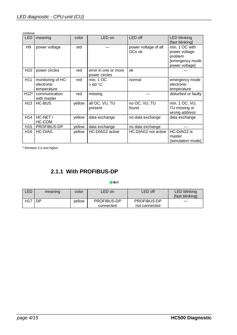
continue
LED meaning color LED on LED off LED blinking [fast blinking]
H9 power voltage red --- power voltage of all OCs ok
min. 1 OC with power voltage problem [emergency mode power voltage]
H10 power circles red error in one or more power circles
ok ---
H11 monitoring of HC-electronic temperature
red min. 1 OC
> 60 C
normal emergency mode electronic temperature
H12* communication with master
red missing --- disturbed or faulty
H13 HC-BUS yellow all OC, VU, TU present
no OC, VU, TU found
min. 1 OC, VU, TU missing or wrong address
H14 HC-NET / HC-COM
yellow data exchange no data exchange data exchange
H15 PROFIBUS-DP yellow data exchange no data exchange ---
H16 HC-DIAG yellow HC-DIAG2 active HC-DIAG2 not active HC-DIAG2 is master [simulation mode]
* firmware 2.0 and higher
2.1.1 With PROFIBUS-DP
LED meaning color LED on LED off LED blinking [fast blinking]
H17 DP yellow PROFIBUS-DP connected
PROFIBUS-DP not connected
---
LED diagnostic - Output-card (OC)
HC500 Diagnostic page 5/15
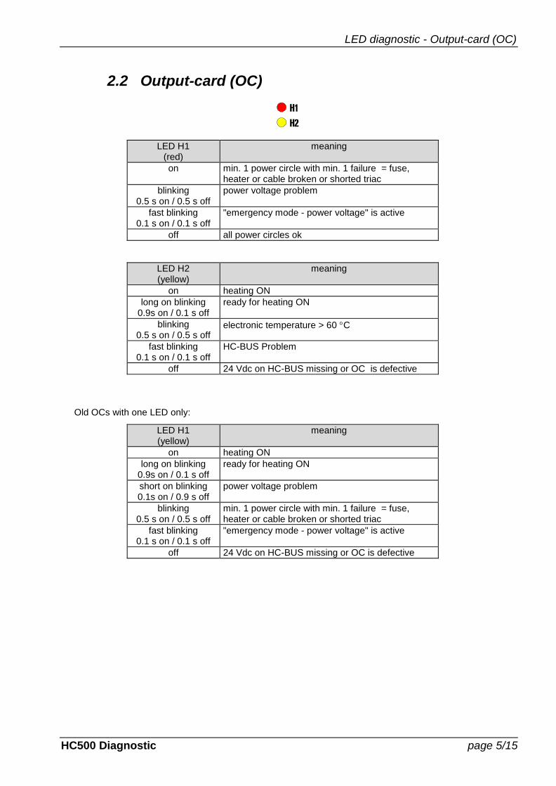
2.2 Output-card (OC)
H1
H2
LED H1 (red)
meaning
on min. 1 power circle with min. 1 failure = fuse, heater or cable broken or shorted triac
blinking 0.5 s on / 0.5 s off
power voltage problem
fast blinking 0.1 s on / 0.1 s off
"emergency mode - power voltage" is active
off all power circles ok
LED H2 (yellow)
meaning
on heating ON
long on blinking 0.9s on / 0.1 s off
ready for heating ON
blinking 0.5 s on / 0.5 s off
electronic temperature > 60 C
fast blinking 0.1 s on / 0.1 s off
HC-BUS Problem
off 24 Vdc on HC-BUS missing or OC is defective
Old OCs with one LED only:
LED H1 (yellow)
meaning
on heating ON
long on blinking 0.9s on / 0.1 s off
ready for heating ON
short on blinking 0.1s on / 0.9 s off
power voltage problem
blinking 0.5 s on / 0.5 s off
min. 1 power circle with min. 1 failure = fuse, heater or cable broken or shorted triac
fast blinking 0.1 s on / 0.1 s off
"emergency mode - power voltage" is active
off 24 Vdc on HC-BUS missing or OC is defective
LED diagnostic - Output-module-master (OMM)
page 6/15 HC500 Diagnostic
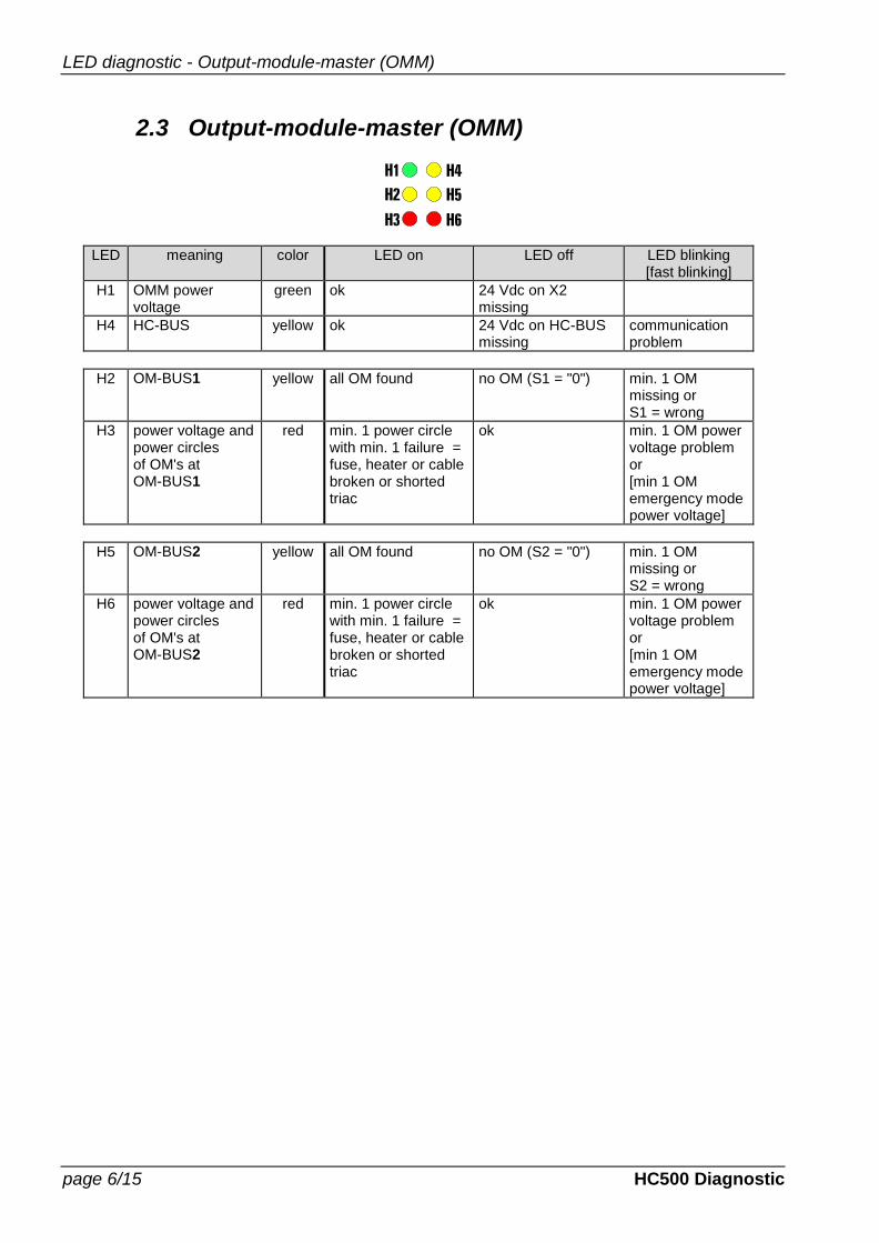
2.3 Output-module-master (OMM)
H1
H2
H3
H4
H5
H6
LED meaning color LED on LED off LED blinking [fast blinking]
H1 OMM power voltage
green ok 24 Vdc on X2 missing
H4 HC-BUS yellow ok 24 Vdc on HC-BUS missing
communication problem
H2 OM-BUS1 yellow all OM found no OM (S1 = "0") min. 1 OM missing or S1 = wrong
H3 power voltage and power circles of OM's at OM-BUS1
red min. 1 power circle with min. 1 failure = fuse, heater or cable broken or shorted triac
ok min. 1 OM power voltage problem or [min 1 OM emergency mode power voltage]
H5 OM-BUS2 yellow all OM found no OM (S2 = "0") min. 1 OM missing or S2 = wrong
H6 power voltage and power circles of OM's at OM-BUS2
red min. 1 power circle with min. 1 failure = fuse, heater or cable broken or shorted triac
ok min. 1 OM power voltage problem or [min 1 OM emergency mode power voltage]

LED diagnostic - Output-module (OM)
HC500 Diagnostic page 7/15
2.4 Output-module (OM)
H1H2
H3H4H5
LED meaning color LED on LED off LED blinking [fast blinking]
H1 power circles red min. 1 power circle with min. 1 failure = fuse, heater or cable broken or shorted triac
ok power voltage problem [emergency mode power voltage]
LED H2 (yellow)
meaning
on heating ON
blinking 0.5 s on / 0.5 s off
HC-BUS problem
fast blinking 0.1 s on / 0.1 s off
electronic temperature > 60 C
short off blinking 0.9s on / 0.1 s off
ready for heating ON
off 24 Vdc on HC-BUS missing or OM is defective
LED meaning color LED on LED off LED blinking [fast blinking]
H4 output 1 green
100% output 1 … 99% output 0 % (no) output H5 output 2 green
H6 output 3 green
LED diagnostic - Output-unit (OU)
page 8/15 HC500 Diagnostic
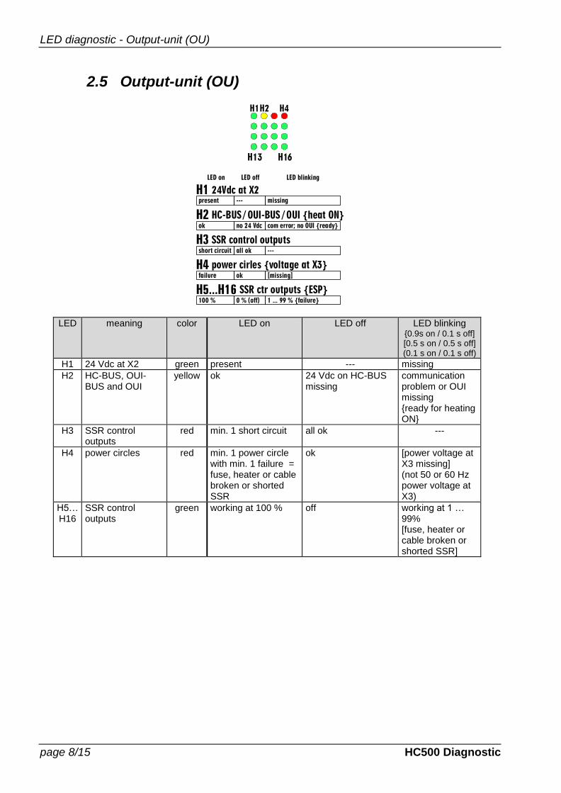
2.5 Output-unit (OU)
H16
H1H2 H4
H13
H1
H2
H3
H4
H5...H16
24Vdc at X2
HC-BUS / OUI-BUS / OUI {heat ON}
SSR control outputs
power cirles {voltage at X3}
SSR ctr outputs {ESP}
LED offLED on
all okshort circuit ---
LED blinking
---present missing
no 24 Vdcok com error; no OUI {ready}
0 % (off)100 % 1 ... 99 % {failure}
okfailure [missing]
LED meaning color LED on LED off LED blinking {0.9s on / 0.1 s off] [0.5 s on / 0.5 s off] (0.1 s on / 0.1 s off)
H1 24 Vdc at X2 green present --- missing
H2 HC-BUS, OUI-BUS and OUI
yellow ok 24 Vdc on HC-BUS missing
communication problem or OUI missing {ready for heating ON}
H3 SSR control outputs
red min. 1 short circuit all ok ---
H4 power circles red min. 1 power circle with min. 1 failure = fuse, heater or cable broken or shorted SSR
ok [power voltage at X3 missing] (not 50 or 60 Hz power voltage at X3)
H5…H16
SSR control outputs
green working at 100 % off working at 1 … 99% [fuse, heater or cable broken or shorted SSR]
LED diagnostic - Output-unit-ampmeter (OUI)
HC500 Diagnostic page 9/15
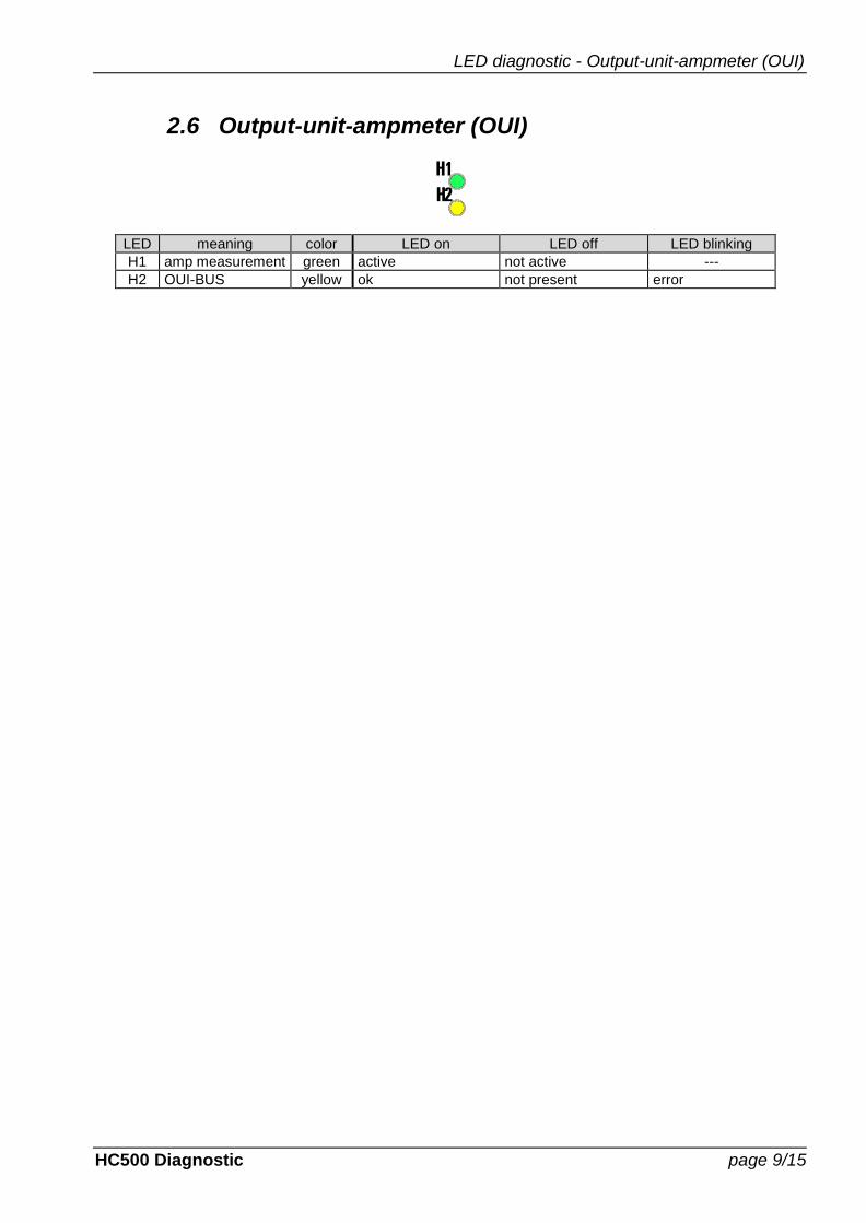
2.6 Output-unit-ampmeter (OUI)
H1
H2
LED meaning color LED on LED off LED blinking
H1 amp measurement green active not active ---
H2 OUI-BUS yellow ok not present error

LED diagnostic - Voltage-unit (VU)
page 10/15 HC500 Diagnostic
2.7 Voltage-unit (VU)
H1
H2
LED meaning color LED on LED off LED blinking
H1 phase voltage L1, L3, L3
red min. 1 phase absent or non 3 different phases
ok all phases not present
H2 HC-BUS yellow ok 24 Vdc on HC-BUS missing
communication problem
LED diagnostic - Temperature-unit
HC500 Diagnostic page 11/15
2.8 Temperature-unit
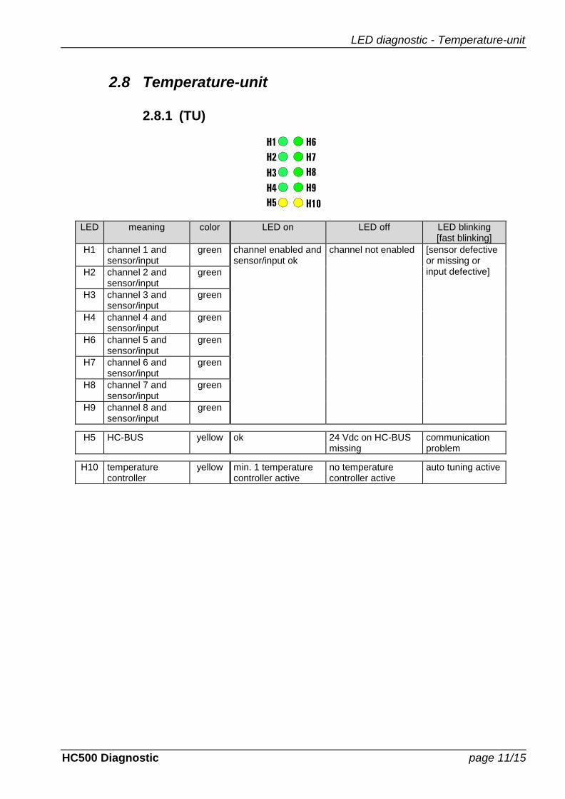
2.8.1 (TU)
H1
H2
H3
H4
H5
H6
H8
H9
H10
H7
LED meaning color LED on LED off LED blinking [fast blinking]
H1 channel 1 and sensor/input
green channel enabled and sensor/input ok
channel not enabled [sensor defective or missing or input defective] H2 channel 2 and
sensor/input green
H3 channel 3 and sensor/input
green
H4 channel 4 and sensor/input
green
H6 channel 5 and sensor/input
green
H7 channel 6 and sensor/input
green
H8 channel 7 and sensor/input
green
H9 channel 8 and sensor/input
green
H5 HC-BUS yellow ok 24 Vdc on HC-BUS missing
communication problem
H10 temperature controller
yellow min. 1 temperature controller active
no temperature controller active
auto tuning active
LED diagnostic - Temperature-unit
page 12/15 HC500 Diagnostic
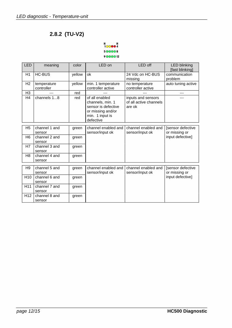
2.8.2 (TU-V2)
LED meaning color LED on LED off LED blinking [fast blinking]
H1 HC-BUS yellow ok 24 Vdc on HC-BUS missing
communication problem
H2 temperature controller
yellow min. 1 temperature controller active
no temperature controller active
auto tuning active
H3 --- red --- --- ---
H4 channels 1...8 red of all enabled channels, min. 1 sensor is defective or missing and/or min. 1 input is defective
inputs and sensors of all active channels are ok
---
H5 channel 1 and sensor
green channel enabled and sensor/input ok
channel enabled and sensor/input ok
[sensor defective or missing or input defective] H6 channel 2 and
sensor green
H7 channel 3 and sensor
green
H8 channel 4 and sensor
green
H9 channel 5 and sensor
green channel enabled and sensor/input ok
channel enabled and sensor/input ok
[sensor defective or missing or input defective] H10 channel 6 and
sensor green
H11 channel 7 and sensor
green
H12 channel 8 and sensor
green
Diagnostic with WINDOWS software
HC500 Diagnostic page 13/15
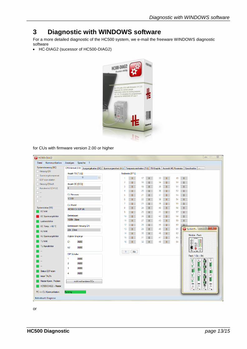
3 Diagnostic with WINDOWS software For a more detailed diagnostic of the HC500 system, we e-mail the freeware WINDOWS diagnostic software
HC-DIAG2 (sucessor of HC500-DIAG2)
for CUs with firmware version 2.00 or higher
or
Diagnostic with WINDOWS software
page 14/15 HC500 Diagnostic
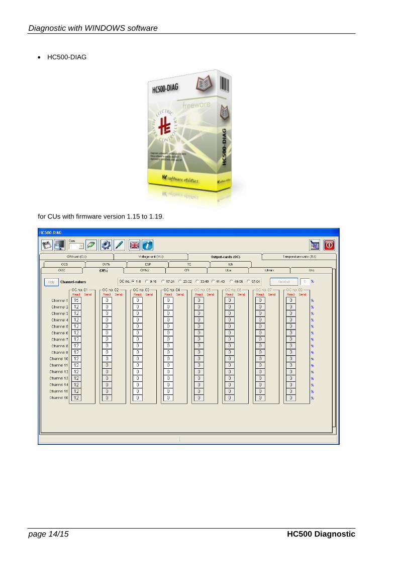
HC500-DIAG
for CUs with firmware version 1.15 to 1.19.
Diagnostic with WINDOWS software
HC500 Diagnostic page 15/15
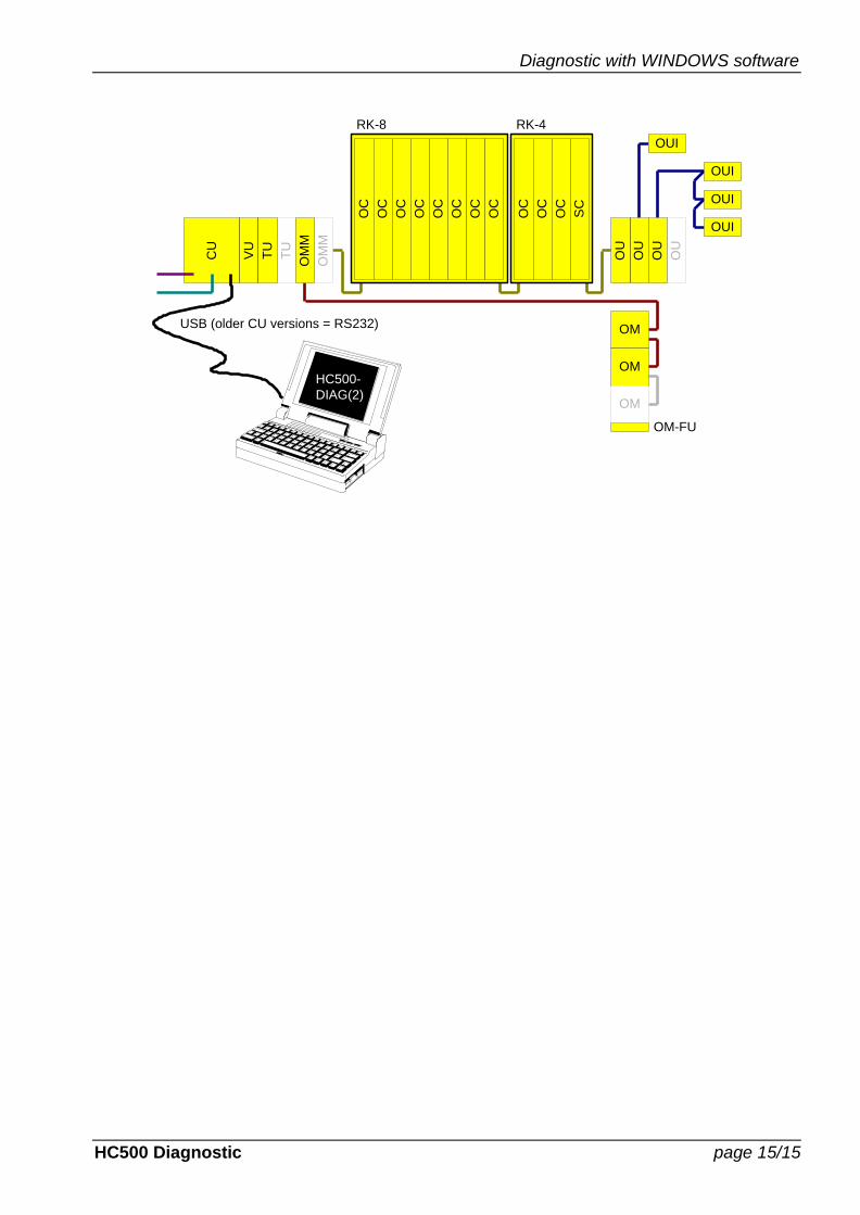
CU
TU
OM
M
VU
OM
M
TU
OC
OC
OC
OC
OC
OC
OC
OC
OC
OC
OC
SC
OM
OM-FU
OM
OM
RK-8 RK-4
OU
OU
OUI
OU
OUI
OUI
OUI
OU
HC500-
DIAG(2)
USB (older CU versions = RS232)