hc-ex54 - välkommen · hc-ex54 with hydraulic control hc-ex54 with electrohydraulic control 11...
TRANSCRIPT
HC-EX54Flow sharing compensated valve
A global partner for innovative solutions
www.hydrocontrol-inc.com
HEAD QUARTERSHydrocontrol SpAVia San Giovanni 481 . 40060 Osteria GrandeCastel S.Pietro Terme . Bologna - ItalyPhone +39.051.6959411 (15 linee)Fax +39.051.946476Phone sales Dep.: +39.051.6959447Fax sales Dep.: [email protected]
U.S.A.Hydrocontrol Inc.1109 Technology Drive . Red Wing, MN 55066 U.S.APhone +1 (651) 212 6400 . Fax +1 (651 212 6401)usa@hydrocontrol-inc-com
GERMANYHydrocontrol GmbHRudolf Diesel Str. 1 42477 RadevormwaldDeutschlandPhone +49 2195-931123 Fax +49 [email protected]
FRANCEHC France SAS7, Rue des Entrepreneurs . Parc de la Vertonne44122 Vertou . FrancePhone +33 02-40332348 . Fax +33 [email protected]
EX54-00 04.2013
INDIAHC Hydraulic Technologies (P) LTDA5 (B) Ngef Ancillary Indl. EstateWhitefield Road . Mahadevpura (Po)Bangalore . 560048IndiaPhone +91 (080) 40454707 Fax +91 (080) [email protected]
CHINAHC China Sales and Production FacilityGuangzhou Bushi Hydraulic Technology LtdShangwei Shaheshe, Yuehu VillageXiancun, Xintang Town . Zengcheng City511335 Guangzhou . Guangdong ProvinceChinaPhone +86 (021) 52380695Fax +86 (021) 52380697fareast@hydrocontrol-inc-com
A global partner for innovative solutions
Functional advantages offered by the EX Family
PATENTED SYSTEMAll the control valves belonging to the EX family work according to a principle designed by Hydrocontrol’s R&D depart-ment and covered by patents EP1860327 (A1) EP1860327 (B1) US2008282691 (A1) and US7581487 (B2).The valve LS signal is managed according to innovative tecnique which is an absolute first in the flow sharing world, ensuring:
• elimination of any LS signal bleed off, which can be observed in most systems currently available commercially, and is often the cause of poor compensation accuracy, slow response and excessive sensitivity to operating conditions.
• LS signal picking downstream of the local compensator: this will make signal detection “neater’’ improving control efficiency and accuracy.
RESPONSE RATEThe EX control valve’s strength resides in its quick, prompt response, achieved thanks to the functional advantages built into our patented system. Even the most critical applications such as excavator bucket shacking and the swift dynamics of forestry machinery, usually hard to achieve on flow sharing systems, can be successfully implemented by using EX family products.
ACCURACY AND STABILITYThe unique technical characteristics of the Hydrocontrol’s patent allows for outstanding flow control and compensation precision, not likely to be affected even by the most diverse operating conditions. Simultaneous functions are never mutually influenced, not even in the presence of the same load factors (an aspect best highlighted in crawler machi-nery travelling). System stability itself is greatly benefited by the EX design; the system, also in combination with traditional overcenter valves, appears well balanced and able to effectively reduce oscillation and dynamic instability.
EFFICIENCYIn addition to the well known advantages typically offered by flow sharing systems which, associated with a variable pump, will drastically reduce the machine operating consumption, the EX family introduces a number of interesting options, including pressure relief on the LS signal to further increase energy saving and guarantee top efficiency levels.
FLEXIBILITYThe EX family control valves can be easily adjusted to a variety of applications, thanks to the wide range of available options and different types of available control systems.
COMPACT DIMENSIONSThe carefully designed features and integrated electrohydraulic control ensure a highly compact and optimised layout. In-tegrated end plates are available in the final working section, adding to the system dimensional and functional efficiency.
PRIORITYThe EX family allow to install side by side pre-compensated section with post-compensated section. This feauture allow to establish a priority in the way the oil is directed and increse the number of application where the EX fa-mily can be applied solving technical difficulties that before required external components. Both Inlets and Outlets remain common for the pre and post compensated sections making the assembling of the valve particularly convenient.
Flow sharing valve
2EX54-00
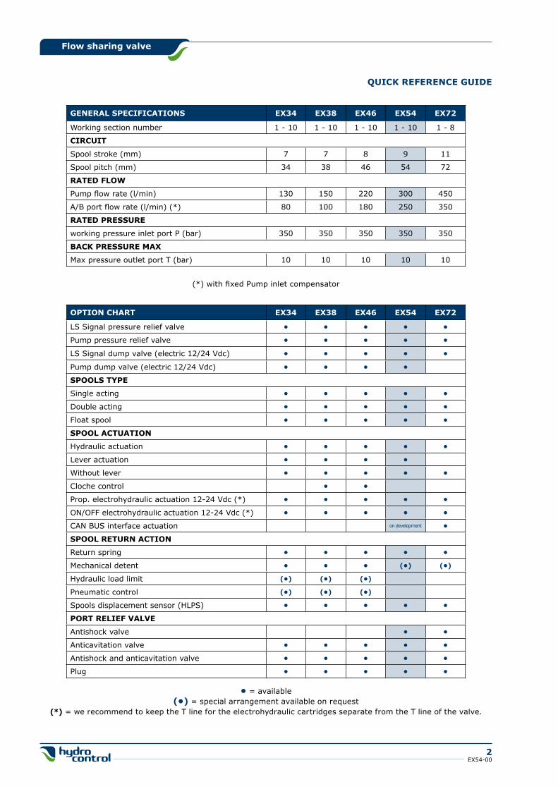
QUICk REFERENCE gUIDE
gENERAL SPECIFICATIONS EX34 EX38 EX46 EX54 EX72
Working section number 1 - 10 1 - 10 1 - 10 1 - 10 1 - 8
CIRCUIT
Spool stroke (mm) 7 7 8 9 11
Spool pitch (mm) 34 38 46 54 72
RATED FLOW
Pump flow rate (l/min) 130 150 220 300 450
A/B port flow rate (l/min) (*) 80 100 180 250 350
RATED PRESSURE
working pressure inlet port P (bar) 350 350 350 350 350
BACk PRESSURE MAX
Max pressure outlet port T (bar) 10 10 10 10 10
(*) with fixed Pump inlet compensator
OPTION ChART EX34 EX38 EX46 EX54 EX72
LS Signal pressure relief valve • • • • •
Pump pressure relief valve • • • • •
LS Signal dump valve (electric 12/24 Vdc) • • • • •
Pump dump valve (electric 12/24 Vdc) • • • •
SPOOLS TYPE
Single acting • • • • •
Double acting • • • • •
Float spool • • • • •
SPOOL ACTUATION
Hydraulic actuation • • • • •
Lever actuation • • • •
Without lever • • • • •
Cloche control • •
Prop. electrohydraulic actuation 12-24 Vdc (*) • • • • •
ON/OFF electrohydraulic actuation 12-24 Vdc (*) • • • • •
CAN BUS interface actuation on development •
SPOOL RETURN ACTION
Return spring • • • • •
Mechanical detent • • • (•) (•)
Hydraulic load limit (•) (•) (•)
Pneumatic control (•) (•) (•)
Spools displacement sensor (HLPS) • • • • •
PORT RELIEF VALVE
Antishock valve • •
Anticavitation valve • • • • •
Antishock and anticavitation valve • • • • •
Plug • • • • •
• = available(•) = special arrangement available on request
(*) = we recommend to keep the T line for the electrohydraulic cartridges separate from the T line of the valve.
Flow sharing valve
3EX54-00
gENERAL INDEX
The specifications detailed in this catalogue show standard products. Special applications are available to order subject to contacting our Engineering Department for an estimate. The data and specifications indicated are to be considered a guide only and Hydrocontrol S.p.A. reserves the right to intro-duce improvements and modifications without prior notice. Hydrocontrol is not responsible for any damage caused by an incorrect use of the product.
4 general specifications Standard working conditions Fluid options Applications Operating principle
6 hydraulic schema Post Compensated system Electrohydraulic control Pre Compensated system Hydraulic control
7 Order example Standard thread Tie-rod kit classification Painting
9 Dimensions HC-EX54 with Hydraulic control HC-EX54 with Electrohydraulic control
11 Typical curves
13 Inlet Section Order example Inlet side classification Valve identification Valve arrangement Inlet classification
17 Working section Order example Spool identification Spool flow Spool actuation classification for hydraulic control Spool actuation classification for electrohydraulic control Work section arrangement Auxiliary valves identification
22 Integrated outlet section Order example Integrated outlet section arrangement
24 hC-EX54 Spare parts list Gasket kits Trasformation kits
28 Installation and maintenance Guidelines General clamping torque Dimensions - Thread codes Dimensions - SAE Flange codes
31 general conditions and patents Product identification
hC-EX54
4EX54-00
Flow sharing valve
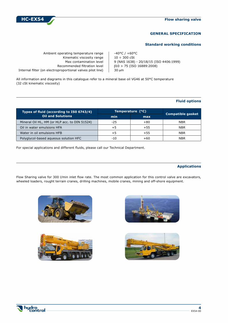
Applications
Flow Sharing valve for 300 l/min inlet flow rate. The most common application for this control valve are excavators, wheeled loaders, rought terrain cranes, drilling machines, mobile cranes, mining and off-shore equipment.
gENERAL SPECIFICATION
Fluid options
Types of fluid (according to IS0 6743/4)Oil and Solutions
Temperature (°C)Compatible gasket
min max
Mineral Oil HL, HM (or HLP acc. to DIN 51524) -25 +80 NBR
Oil in water emulsions HFA +5 +55 NBR
Water in oil emulsions HFB +5 +55 NBR
Polyglycol-based aqueous solution HFC -10 +60 NBR
For special applications and different fluids, please call our Technical Department.
Standard working conditions
All information and diagrams in this catalogue refer to a mineral base oil VG46 at 50°C temperature(32 cSt kinematic viscosity)
Ambient operating temperature range -40°C / +60°C Kinematic viscosity range 10 ÷ 300 cSt Max contamination level 9 (NAS 1638) - 20/18/15 (ISO 4406:1999) Recommended filtration level b10 > 75 (ISO 16889:2008) Internal filter (on electroproportional valves pilot line) 30 μm

hC-EX54
5EX54-00
Flow sharing valve
Operating principle
Single section
Multi-section
The flow sharing technology applied to the standard load sensing system characterizes the new control valves HC-EX. The valve, completely pressure compensated, guarantees great controllability to all actuations, making workport flow dependent only on metering area (spool position). When flow saturation occurs the system reacts by implementing an equal reduction of pressure margin across all spools, generating a proportional reduction of workport flow.
2
3
Workport A
54
1 Workport B
Flow Sharing function
Referring to picture it’s possible to remark some aspects of system functionality. Coming from the common inlet line the main flow, passing across the metering area, reaches local compensator. Metering area, according to the pressure margin, controls the total amount of flow to the workport selected by the main spool. The load sensing signal, picked up downstream the local compensator, feeds the common load-sensing line. When a single section is actuated, the local compensator fully opens to the left side, reaching its complete balanced position. The control of the LS system is made by the inlet compensator for fixed displacement pump or pump compensator for variable displacement pump.
When two or more sections are actuated only one, characterized by the highest pressure (dominant), is involved in the LS signal transmission, working as briefly described in the previous paragraph. The other functions (slaves) become directly dependent on it. The common LS line transfers the information coming from the dominant local compensator to all dependent compensators. Driven by the LS signal, the unbalanced slave compensators activate the pressure compensation creating an artificial pressure drop able to keep pressure margin nominally the same on all the spools. Workport flow becomes only a function of metering area making the system totally load independent.
When saturation occurs the total amount of flow required by actuations is higher than the maximum pump flow rate. The system is able to keep the nominal pressure margin no more. The actual pressure margin reduces according to real flow demand. Since all the local compensators feel the same LS signal and the same pressure drop is applied to different metering areas, then workport flows are reduced proportionally in order to keep all actuations completely under control.
LEgEND:
1. Inlet line (High pressure)2. Metering notches3. Load sensing line4. Local compensator5. Metering spool
hC-EX54
6EX54-00
Flow sharing valve
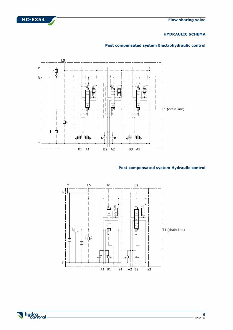
hYDRAULIC SChEMA
LS
R
P
T
B1 A1 B2 A2 B3 A3
T1 (drain line)
Post compensated system hydraulic control
M
P
LS
T
T1 (drain line)
b2b1
A1 B1 a1 A2 B2 a2
Post compensated system Electrohydraulic control

hC-EX54
7EX54-00
Flow sharing valve
ORDER EXAMPLE
TYPE: EX54: product type /2: working section number
1) INLET ARRANgEMENT: MR 701 inlet side and valve type 200 setting (bar) kV S35 inlet position and available thread type
2) WORk SECTION ARRANgEMENT: W001C 5050 type and spool delivery h005C spool actuation type RC1 g06 section type and port threads 04 PA 350 auxiliary valve (port A) 04 PB 350 auxiliary valve (port B)
3) INTEgRATED OUTLET SECTION ARRANgEMENT: W001C 5050 type and spool delivery h005C spool actuation type RCk1A g06 section type and port threads 05 PA auxiliary valve (port A) 05 PB auxiliary valve (port B)
hC-EX54/2: MR 701 200 kV S35 - W001C 5050 h005C RC1 g06 04 PA 350 04 PB 350 - W001C 5050 h005C RCk1A g06 05 PA 05 PB
Ordering row 2 must be repeated for every work section
Ports BSP (ISO - 228) UN-UNF (ISO - 725) SAE 3000 (ISO 6162-1) SAE 6000 (ISO 6162-2)
P G 1”1/4 1”5/8 - 12 UNF 1” MA - 1” UNC
T G 1”1/4 1”5/8 - 12 UNF 1”1/4 MA - 1”1/4 UNC
A - B G 1” 1”5/16 - 12 UNF 3/4” MA - 3/4” UNC
Standard threadThe connection ports size is indicated by an ordering code common for all Hydrocontrol products. Following table shows all available connections; for ordering code refer to table on page 30.
PT
1
2B
A
3B
A
hC-EX54
8EX54-00
Flow sharing valve
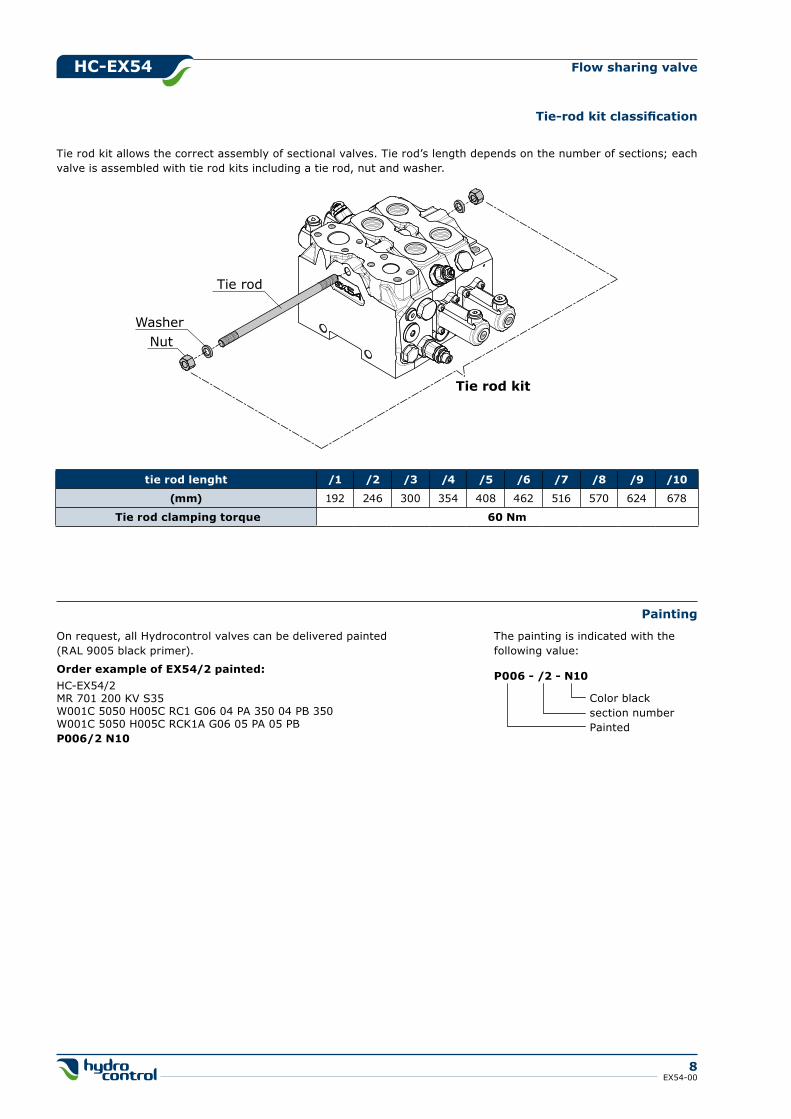
Tie-rod kit classification
Tie rod kit allows the correct assembly of sectional valves. Tie rod’s length depends on the number of sections; each valve is assembled with tie rod kits including a tie rod, nut and washer.
Tie rod
NutWasher
Tie rod kit
tie rod lenght /1 /2 /3 /4 /5 /6 /7 /8 /9 /10
(mm) 192 246 300 354 408 462 516 570 624 678
Tie rod clamping torque 60 Nm
Painting
On request, all Hydrocontrol valves can be delivered painted(RAL 9005 black primer).
Order example of EX54/2 painted:HC-EX54/2MR 701 200 KV S35W001C 5050 H005C RC1 G06 04 PA 350 04 PB 350W001C 5050 H005C RCK1A G06 05 PA 05 PBP006/2 N10
P006 - /2 - N10
Color black section number Painted
The painting is indicated with the following value:
hC-EX54
9EX54-00
Flow sharing valve
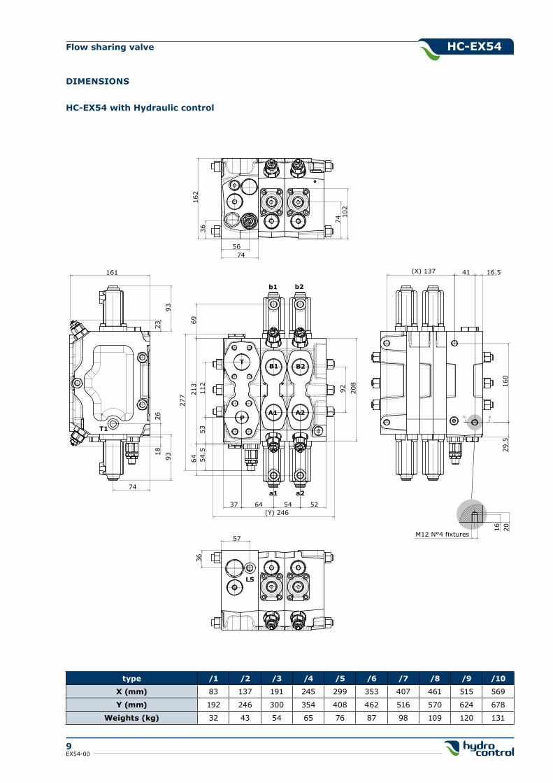
DIMENSIONS
T
PA1 A2
B1 B2
b1 b2
a1 a2
69
277 21
3
92112
54.5
6453
37 64 54 52(Y) 246
208
T1
74
2618
9393
23
161
162
36
102
74
5674
36
57
160
29.5
41 16.5(X) 137
M12 N°4 fixtures
2016
LS
type /1 /2 /3 /4 /5 /6 /7 /8 /9 /10
X (mm) 83 137 191 245 299 353 407 461 515 569
Y (mm) 192 246 300 354 408 462 516 570 624 678
Weights (kg) 32 43 54 65 76 87 98 109 120 131
hC-EX54 with hydraulic control
hC-EX54
10EX54-00
Flow sharing valve
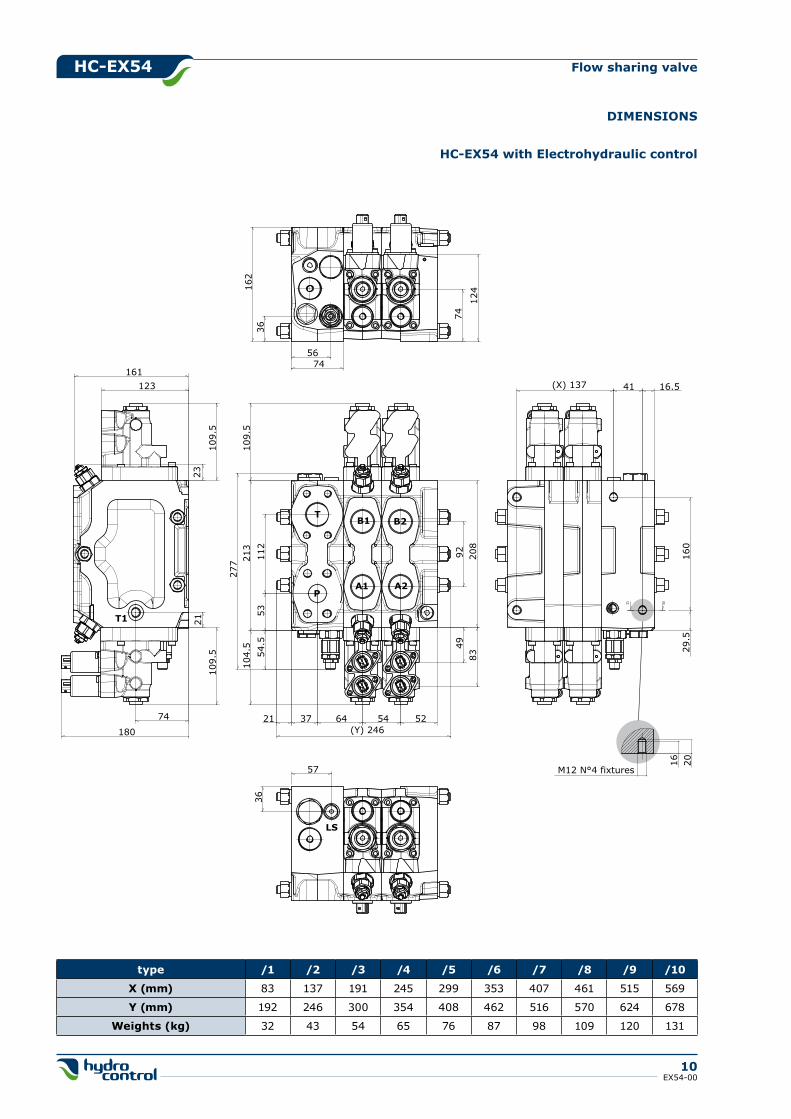
DIMENSIONS
type /1 /2 /3 /4 /5 /6 /7 /8 /9 /10
X (mm) 83 137 191 245 299 353 407 461 515 569
Y (mm) 192 246 300 354 408 462 516 570 624 678
Weights (kg) 32 43 54 65 76 87 98 109 120 131
M12 N°4 fixtures
201616
029
.5
41 16.5(X) 137
36
57
LS
36
5674
162
74
124
T1
180
109.
510
9.5
161
2321
74
123
T
PA1 A2
B1 B2
277 21
3
92112
54.5
53
37 64 54 52(Y) 246
109.
510
4.5
208
21
4983
hC-EX54 with Electrohydraulic control
hC-EX54
11EX54-00
Flow sharing valve
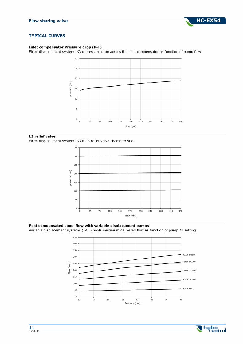
TYPICAL CURVES
Inlet compensator Pressure drop (P-T)Fixed displacement system (KV): pressure drop across the inlet compensator as function of pump flow
0
5
10
15
20
25
30
pres
sure
[ba
r]
0 35 70 105 140 175 210 245 280 315 350
flow [l/m]
LS relief valveFixed displacement system (KV): LS relief valve characteristic
0
50
100
150
200
250
300
350
pres
sure
[ba
r]
flow [l/m]
0 35 70 105 140 175 210 245 280 315 350
Post compensated spool flow with variable displacement pumpsVariable displacement systems (JV): spools maximum delivered flow as function of pump DP setting
0
50
100
150
200
250
300
Flow
[l/
min
]
12 14 16 18 20 22 24 26
Pressure [bar]
Spool 250250
Spool 200200
Spool 150150
Spool 100100
Spool 5050
350
400
450
hC-EX54
12EX54-00
Flow sharing valve
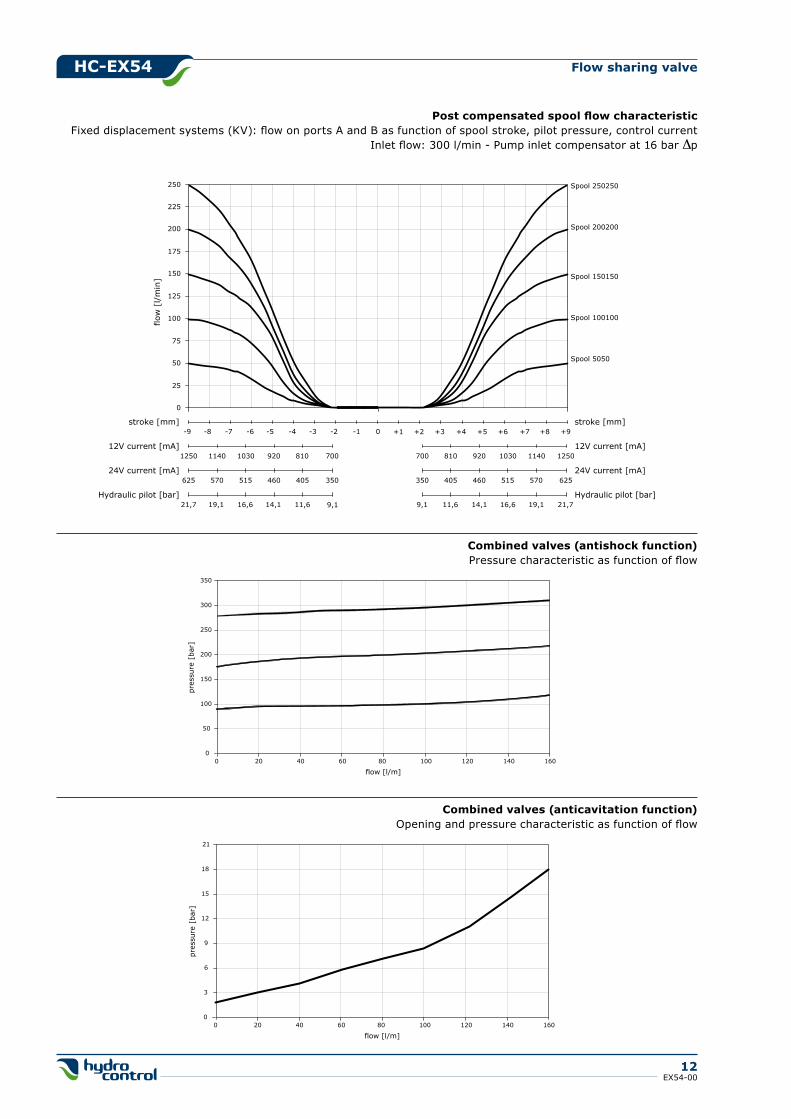
Post compensated spool flow characteristicFixed displacement systems (KV): flow on ports A and B as function of spool stroke, pilot pressure, control current
Inlet flow: 300 l/min - Pump inlet compensator at 16 bar Dp
0
100
75
50
25
125
150
175
200
225
250
flow
[l/
min
]
0-1-2-3-4-5-6-7 +1 +2 +3 +4 +5 +6 +7stroke [mm]
700 810 920 1030 125012V current [mA]
350 405 460 515
1140
570 62524V current [mA]
9,1 11,6 14,1 16,6 19,1 21,7Hydraulic pilot [bar]
stroke [mm]
12V current [mA]
24V current [mA]
Hydraulic pilot [bar]
Spool 250250
Spool 200200
Spool 150150
Spool 100100
Spool 5050
1250 1140 1030 920 700
625 570 515 460
810
405 350
21,7 19,1 16,6 14,1 11,6 9,1
-8-9 +8 +9
Combined valves (antishock function)Pressure characteristic as function of flow
0
50
100
150
200
250
300
350
0 20 40 60 80 100 120 140 160
flow [l/m]
pres
sure
[ba
r]
Combined valves (anticavitation function)Opening and pressure characteristic as function of flow
0
3
6
9
12
15
18
21
0 20 40 60 80 100 120 140 160
flow [l/m]
pres
sure
[ba
r]
hC-EX54
13EX54-00
Flow sharing valve
MR inlet side
1. 701 valve arrangement
200 setting (bar)
2. kV S35 inlet position and available thread type
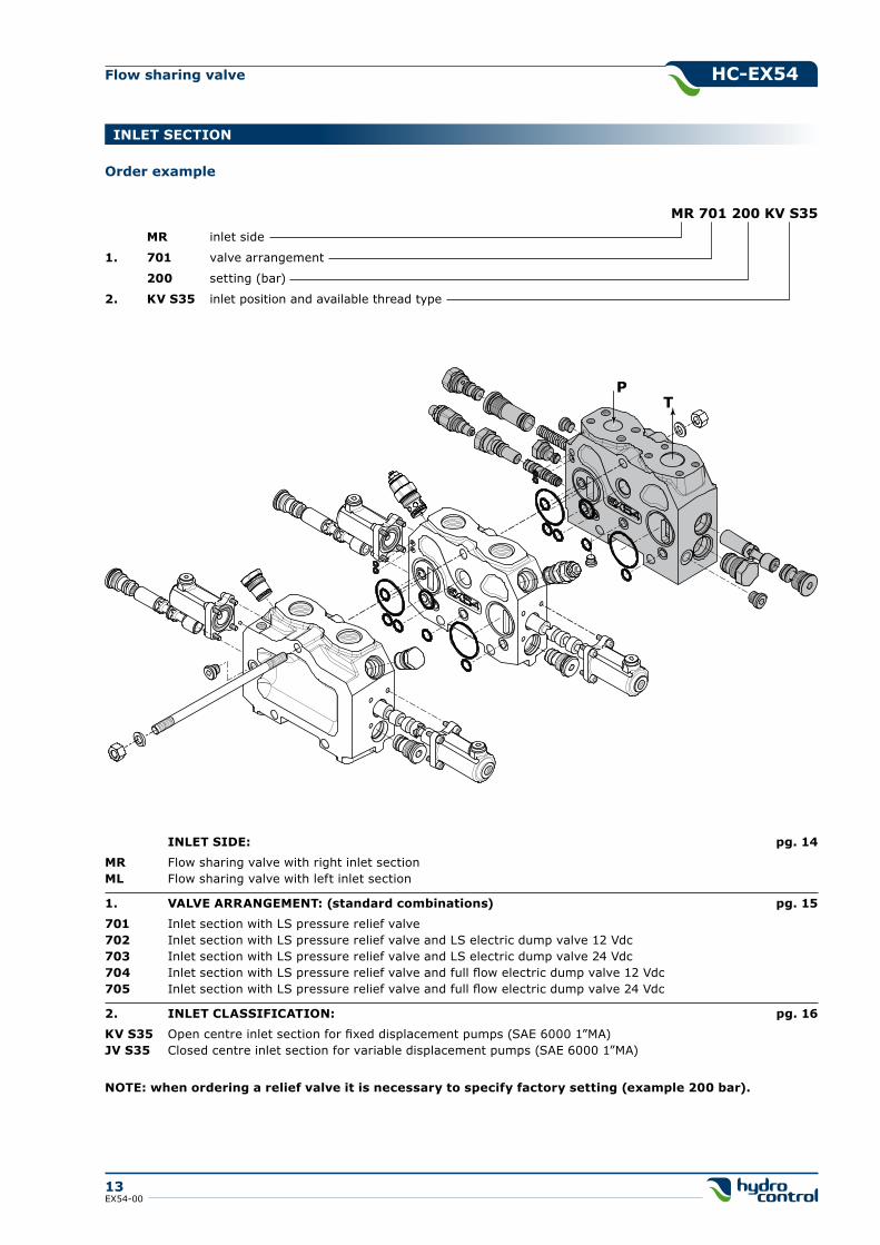
INLET SECTION
MR 701 200 kV S35
PT
INLET SIDE: pg. 14
MR Flow sharing valve with right inlet sectionML Flow sharing valve with left inlet section
1. VALVE ARRANgEMENT: (standard combinations) pg. 15
701 Inlet section with LS pressure relief valve702 Inlet section with LS pressure relief valve and LS electric dump valve 12 Vdc703 Inlet section with LS pressure relief valve and LS electric dump valve 24 Vdc704 Inlet section with LS pressure relief valve and full flow electric dump valve 12 Vdc705 Inlet section with LS pressure relief valve and full flow electric dump valve 24 Vdc
2. INLET CLASSIFICATION: pg. 16
kV S35 Open centre inlet section for fixed displacement pumps (SAE 6000 1”MA)JV S35 Closed centre inlet section for variable displacement pumps (SAE 6000 1”MA)
NOTE: when ordering a relief valve it is necessary to specify factory setting (example 200 bar).
Order example
hC-EX54
14EX54-00
Flow sharing valve
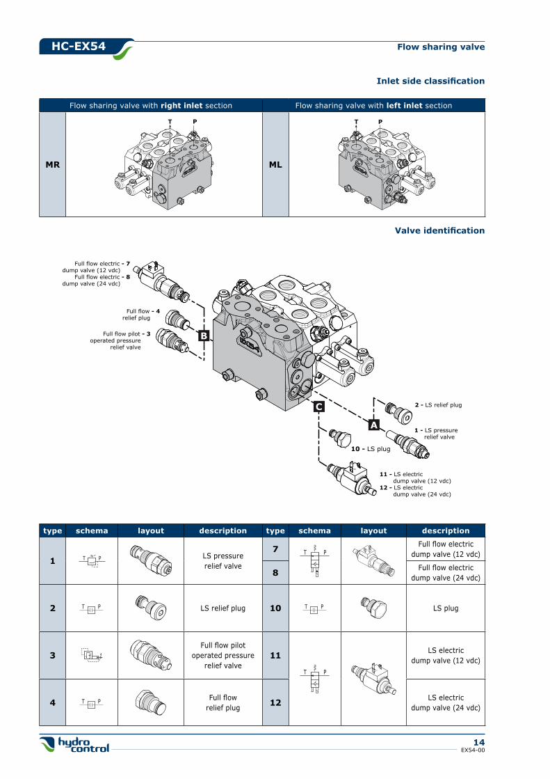
Inlet side classification
Flow sharing valve with right inlet section Flow sharing valve with left inlet section
MR ML
PT PT
A1 - LS pressure relief valve
Full flow pilot - 3operated pressure
relief valve
Full flow - 4relief plug
Full flow electric - 7dump valve (12 vdc)
Full flow electric - 8dump valve (24 vdc)
2 - LS relief plug
10 - LS plug
11 - LS electric dump valve (12 vdc)12 - LS electric dump valve (24 vdc)
C
B
type schema layout description type schema layout description
1 LS pressurerelief valve
7 Full flow electricdump valve (12 vdc)
8 Full flow electricdump valve (24 vdc)
2 LS relief plug 10 LS plug
3Full flow pilot
operated pressure relief valve
11 LS electricdump valve (12 vdc)
4 Full flowrelief plug 12 LS electric
dump valve (24 vdc)
Valve identification
T P
T P
T P
T P
T P
T P
hC-EX54
15EX54-00
Flow sharing valve
Valve arrangement
AC
B
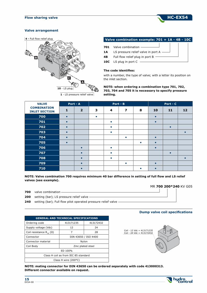
4 - Full flow relief plug
1 - LS pressure relief valve
10 - LS plug
701 Valve combination
1A LS pressure relief valve in port A
4B Full flow relief plug in port B
10C LS plug in port C
The code identifies:
with a number, the type of valve; with a letter its position on the inlet section.
NOTE: when ordering a combination type 701, 702, 703, 704 and 705 it is necessary to specify pressure setting.
Valve combination example: 701 = 1A - 4B - 10C
VALVE COMBINATIONINLET SECTION
Port - A Port - B Port - C
1 2 3 4 7 8 10 11 12
700 • • •
701 • • •
702 • • •
703 • • •
704 • • •
705 • • •
706 • • •
707 • • •
708 • • •
709 • • •
710 • • •
NOTE: Valve combination 700 requires minimum 40 bar difference in setting of full flow and LS relief valves (see example).
700 valve combination
200 setting (bar); LS pressure relief valve
240 setting (bar); Full flow pilot operated pressure relief valve
MR 700 200*240 KV G05
gENERAL AND TEChNICAL SPECIFICATIONS
Ordering code 413171235 413172432
Supply voltage (Vdc) 12 24
Coil resistance R20 (Ω) 7 28
Connector DIN 43650 / ISO 4400
Connector material Nylon
Coil Body Zinc plated steel
ED 100%
Class H coil as from IEC 85 standard
Class H wire (200°C)
NOTE: mating connector for DIN 43650 can be ordered separately with code 413000313.Different connector available on request.
Dump valve coil specifications
Coil - 12 Vdc = 413171235Coil - 24 Vdc = 413172432
hC-EX54
16EX54-00
Flow sharing valve
Inlet classification
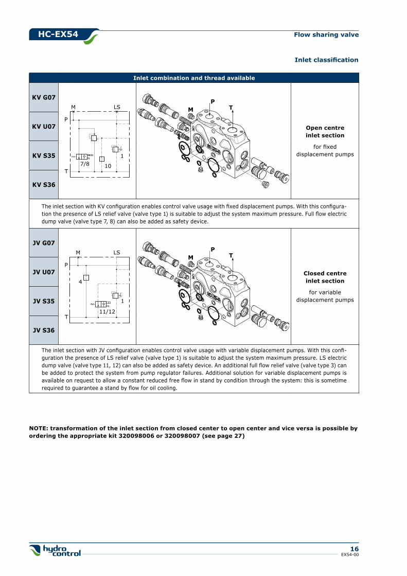
Inlet combination and thread available
kV g07
Open centreinlet section
for fixeddisplacement pumps
kV U07
kV S35
kV S36
The inlet section with KV configuration enables control valve usage with fixed displacement pumps. With this configura-tion the presence of LS relief valve (valve type 1) is suitable to adjust the system maximum pressure. Full flow electric dump valve (valve type 7, 8) can also be added as safety device.
JV g07
Closed centreinlet section
for variabledisplacement pumps
JV U07
JV S35
JV S36
The inlet section with JV configuration enables control valve usage with variable displacement pumps. With this confi-guration the presence of LS relief valve (valve type 1) is suitable to adjust the system maximum pressure. LS electric dump valve (valve type 11, 12) can also be added as safety device. An additional full flow relief valve (valve type 3) can be added to protect the system from pump regulator failures. Additional solution for variable displacement pumps is available on request to allow a constant reduced free flow in stand by condition through the system: this is sometime required to guarantee a stand by flow for oil cooling.
LS
P
T
M
1
107/8
LS
P
T
M
4
1
11/12
PTM
PTM
NOTE: transformation of the inlet section from closed center to open center and vice versa is possible by ordering the appropriate kit 320098006 or 320098007 (see page 27)
hC-EX54
17EX54-00
Flow sharing valve
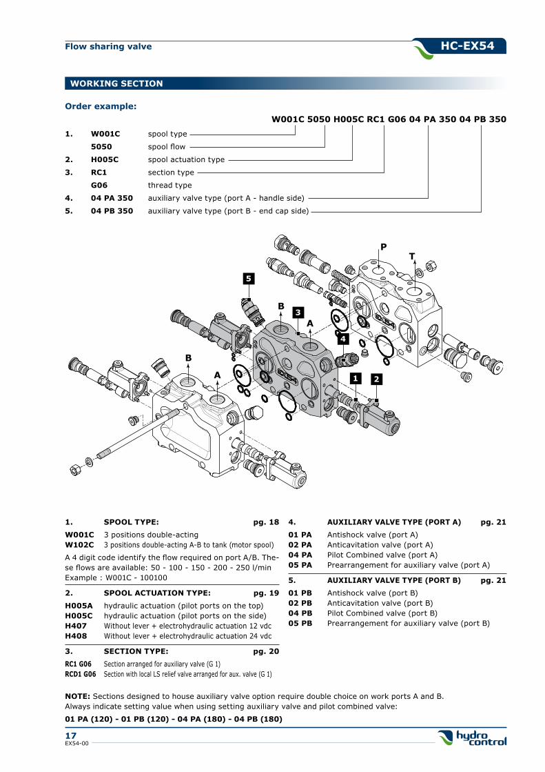
1. W001C spool type
5050 spool flow
2. h005C spool actuation type
3. RC1 section type
g06 thread type
4. 04 PA 350 auxiliary valve type (port A - handle side)
5. 04 PB 350 auxiliary valve type (port B - end cap side)
Order example:W001C 5050 h005C RC1 g06 04 PA 350 04 PB 350
WORkINg SECTION
1. SPOOL TYPE: pg. 18
W001C 3 positions double-actingW102C 3 positions double-acting A-B to tank (motor spool)
A 4 digit code identify the flow required on port A/B. The-se flows are available: 50 - 100 - 150 - 200 - 250 l/minExample : W001C - 100100
2. SPOOL ACTUATION TYPE: pg. 19
h005A hydraulic actuation (pilot ports on the top)h005C hydraulic actuation (pilot ports on the side)h407 Without lever + electrohydraulic actuation 12 vdch408 Without lever + electrohydraulic actuation 24 vdc
3. SECTION TYPE: pg. 20
RC1 g06 Section arranged for auxiliary valve (G 1)RCD1 g06 Section with local LS relief valve arranged for aux. valve (G 1)
4. AUXILIARY VALVE TYPE (PORT A) pg. 21
01 PA Antishock valve (port A)02 PA Anticavitation valve (port A)04 PA Pilot Combined valve (port A)05 PA Prearrangement for auxiliary valve (port A)
5. AUXILIARY VALVE TYPE (PORT B) pg. 21
01 PB Antishock valve (port B)02 PB Anticavitation valve (port B)04 PB Pilot Combined valve (port B)05 PB Prearrangement for auxiliary valve (port B)
PT
1
B
A
B
A 2
3
5
4
NOTE: Sections designed to house auxiliary valve option require double choice on work ports A and B.Always indicate setting value when using setting auxiliary valve and pilot combined valve:
01 PA (120) - 01 PB (120) - 04 PA (180) - 04 PB (180)
hC-EX54
18EX54-00
Flow sharing valve
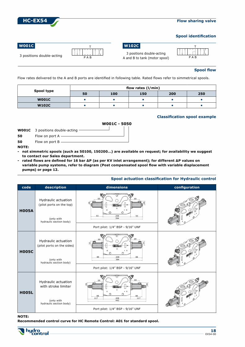
W001C 3 positions double-acting
50 Flow on port A
50 Flow on port B
Spool identification
W001C T
P A B3 positions double-acting
W102C T
P A B3 positions double-acting
A and B to tank (motor spool)
Flow rates delivered to the A and B ports are identified in following table. Rated flows refer to simmetrical spools.
Spool flow
W001C - 5050
Spool typeflow rates (l/min)
50 100 150 200 250
W001C • • • • •
W102C • • • • •
NOTE:- not simmetric spools (such as 50100, 150200...) are available on request; for availability we suggest to contact our Sales department.- rated flows are defined for 16 bar ΔP (as per kV inlet arrangement); for different ΔP values on variable pump systems, refer to diagram (Post compensated spool flow with variable displacement pumps) or page 12.
Classification spool example
Spool actuation classification for hydraulic control
code description dimensions configuration
h005A
Hydraulic actuation(pilot ports on the top)
(only withhydraulic section body)
Port pilot: 1/4” BSP - 9/16” UNF
h005C
Hydraulic actuation(pilot ports on the sides)
(only withhydraulic section body)
Port pilot: 1/4” BSP - 9/16” UNF
h005L
Hydraulic actuationwith stroke limiter
(only withhydraulic section body)
Port pilot: 1/4” BSP - 9/16” UNF
93 208 93
28
69 69
28
394
88 208 88
6969
33 33
384
88 88117208117
442
28 28
6969
NOTE:Recommended control curve for hC Remote Control: A01 for standard spool.
hC-EX54
19EX54-00
Flow sharing valve
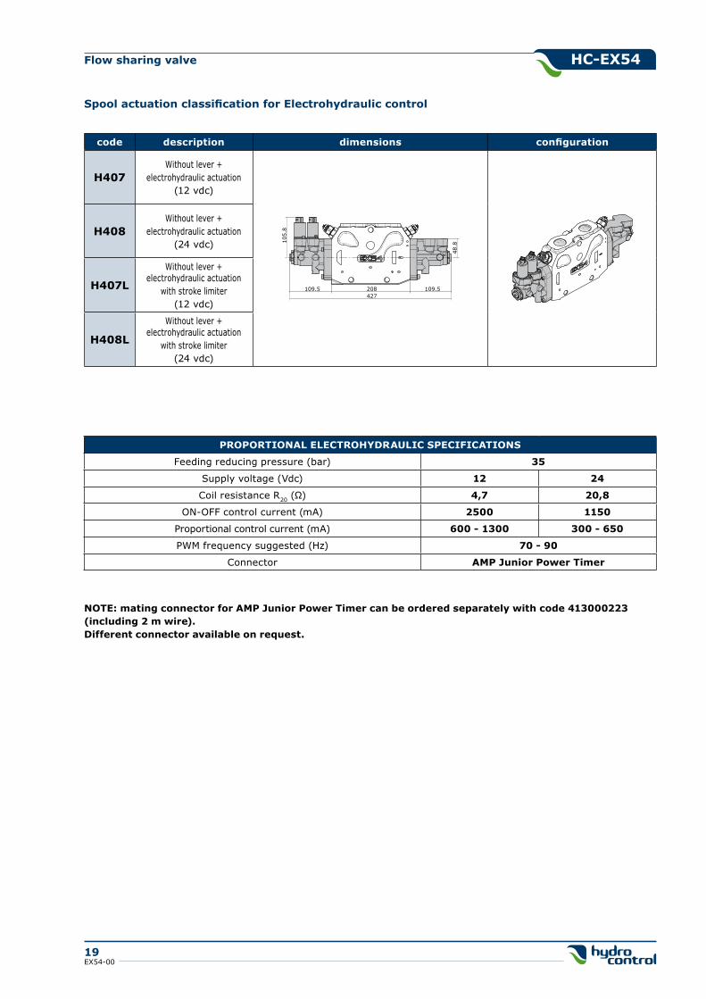
Spool actuation classification for Electrohydraulic control
code description dimensions configuration
h407Without lever +
electrohydraulic actuation(12 vdc)
h408Without lever +
electrohydraulic actuation(24 vdc)
h407L
Without lever +electrohydraulic actuation
with stroke limiter(12 vdc)
h408L
Without lever +electrohydraulic actuation
with stroke limiter(24 vdc)
109.5 208 109.510
5.8
48.8
427
PROPORTIONAL ELECTROhYDRAULIC SPECIFICATIONS
Feeding reducing pressure (bar) 35
Supply voltage (Vdc) 12 24
Coil resistance R20 (Ω) 4,7 20,8
ON-OFF control current (mA) 2500 1150
Proportional control current (mA) 600 - 1300 300 - 650
PWM frequency suggested (Hz) 70 - 90
Connector AMP Junior Power Timer
NOTE: mating connector for AMP Junior Power Timer can be ordered separately with code 413000223(including 2 m wire).Different connector available on request.
hC-EX54
20EX54-00
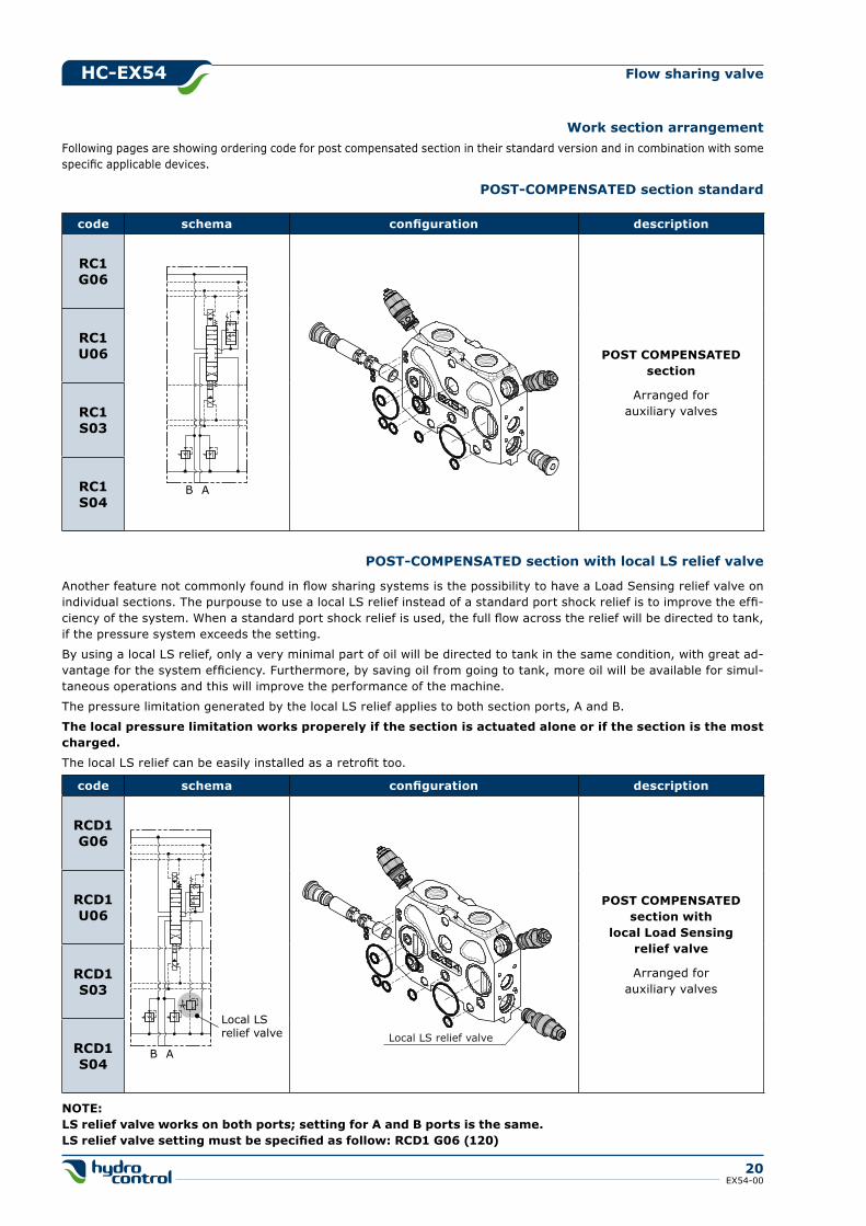
Flow sharing valve
Work section arrangementFollowing pages are showing ordering code for post compensated section in their standard version and in combination with some specific applicable devices.
code schema configuration description
RC1g06
POST COMPENSATEDsection
Arranged forauxiliary valves
RC1U06
RC1S03
RC1S04
AB
POST-COMPENSATED section standard
code schema configuration description
RCD1g06
POST COMPENSATEDsection with
local Load Sensingrelief valve
Arranged forauxiliary valves
RCD1U06
RCD1S03
RCD1S04
Local LSrelief valve
AB
POST-COMPENSATED section with local LS relief valve
Another feature not commonly found in flow sharing systems is the possibility to have a Load Sensing relief valve on individual sections. The purpouse to use a local LS relief instead of a standard port shock relief is to improve the effi-ciency of the system. When a standard port shock relief is used, the full flow across the relief will be directed to tank, if the pressure system exceeds the setting.
By using a local LS relief, only a very minimal part of oil will be directed to tank in the same condition, with great ad-vantage for the system efficiency. Furthermore, by saving oil from going to tank, more oil will be available for simul-taneous operations and this will improve the performance of the machine.
The pressure limitation generated by the local LS relief applies to both section ports, A and B.
The local pressure limitation works properely if the section is actuated alone or if the section is the most charged.
The local LS relief can be easily installed as a retrofit too.
NOTE:LS relief valve works on both ports; setting for A and B ports is the same.LS relief valve setting must be specified as follow: RCD1 g06 (120)
Local LS relief valve
hC-EX54
21EX54-00
Flow sharing valve
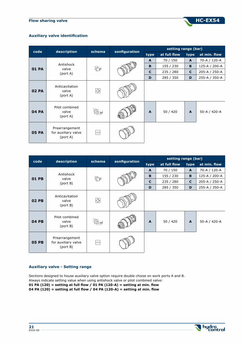
Auxiliary valve identification
code description schema sonfigurationsetting range (bar)
type at full flow type at min. flow
01 PAAntishock
valve(port A)
A 70 / 150 A 70-A / 120-A
B 155 / 230 B 125-A / 200-A
C 235 / 280 C 205-A / 250-A
D 285 / 350 D 255-A / 350-A
02 PAAnticavitation
valve(port A)
04 PAPilot combined
valve(port A)
A 50 / 420 A 50-A / 420-A
05 PAPrearrangement
for auxiliary valve(port A)
Auxiliary valve - Setting range
Sections designed to house auxiliary valve option require double choise on work ports A and B.Always indicate setting value when using antishock valve or pilot combined valve:01 PA (120) = setting at full flow / 01 PA (120-A) = setting at min. flow04 PA (120) = setting at full flow / 04 PA (120-A) = setting at min. flow
code description schema sonfigurationsetting range (bar)
type at full flow type at min. flow
01 PBAntishock
valve(port B)
A 70 / 150 A 70-A / 120-A
B 155 / 230 B 125-A / 200-A
C 235 / 280 C 205-A / 250-A
D 285 / 350 D 255-A / 350-A
02 PBAnticavitation
valve(port B)
04 PBPilot combined
valve(port B)
A 50 / 420 A 50-A / 420-A
05 PBPrearrangement
for auxiliary valve(port B)
hC-EX54
22EX54-00
Flow sharing valve
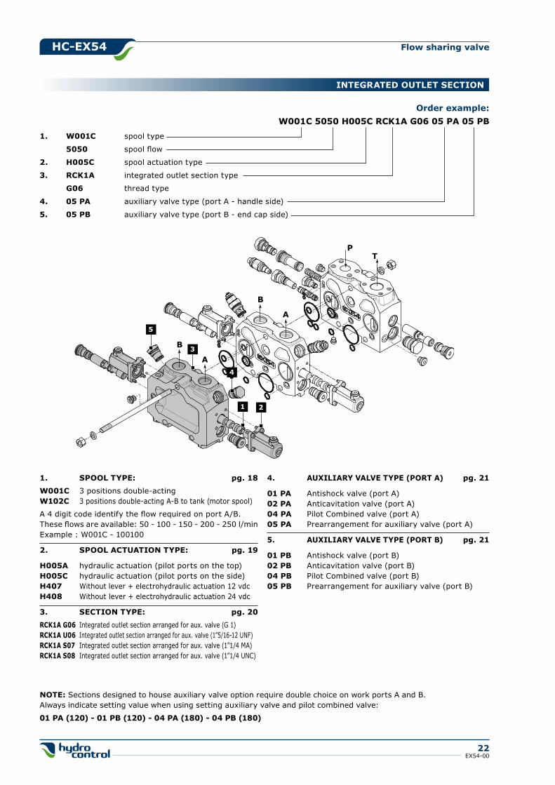
1. W001C spool type
5050 spool flow
2. h005C spool actuation type
3. RCk1A integrated outlet section type
g06 thread type
4. 05 PA auxiliary valve type (port A - handle side)
5. 05 PB auxiliary valve type (port B - end cap side)
Order example:W001C 5050 h005C RCk1A g06 05 PA 05 PB
1. SPOOL TYPE: pg. 18
W001C 3 positions double-actingW102C 3 positions double-acting A-B to tank (motor spool)
A 4 digit code identify the flow required on port A/B.These flows are available: 50 - 100 - 150 - 200 - 250 l/minExample : W001C - 100100
2. SPOOL ACTUATION TYPE: pg. 19
h005A hydraulic actuation (pilot ports on the top)h005C hydraulic actuation (pilot ports on the side)h407 Without lever + electrohydraulic actuation 12 vdch408 Without lever + electrohydraulic actuation 24 vdc
3. SECTION TYPE: pg. 20
RCk1A g06 Integrated outlet section arranged for aux. valve (G 1)RCk1A U06 Integrated outlet section arranged for aux. valve (1”5/16-12 UNF)RCk1A S07 Integrated outlet section arranged for aux. valve (1”1/4 MA)RCk1A S08 Integrated outlet section arranged for aux. valve (1”1/4 UNC)
4. AUXILIARY VALVE TYPE (PORT A) pg. 21
01 PA Antishock valve (port A)02 PA Anticavitation valve (port A)04 PA Pilot Combined valve (port A)05 PA Prearrangement for auxiliary valve (port A)
5. AUXILIARY VALVE TYPE (PORT B) pg. 21
01 PB Antishock valve (port B)02 PB Anticavitation valve (port B)04 PB Pilot Combined valve (port B)05 PB Prearrangement for auxiliary valve (port B)
NOTE: Sections designed to house auxiliary valve option require double choice on work ports A and B.Always indicate setting value when using setting auxiliary valve and pilot combined valve:
01 PA (120) - 01 PB (120) - 04 PA (180) - 04 PB (180)
PT
B
A
B
A
1 2
3
5
4
INTEgRATED OUTLET SECTION
hC-EX54
23EX54-00
Flow sharing valve
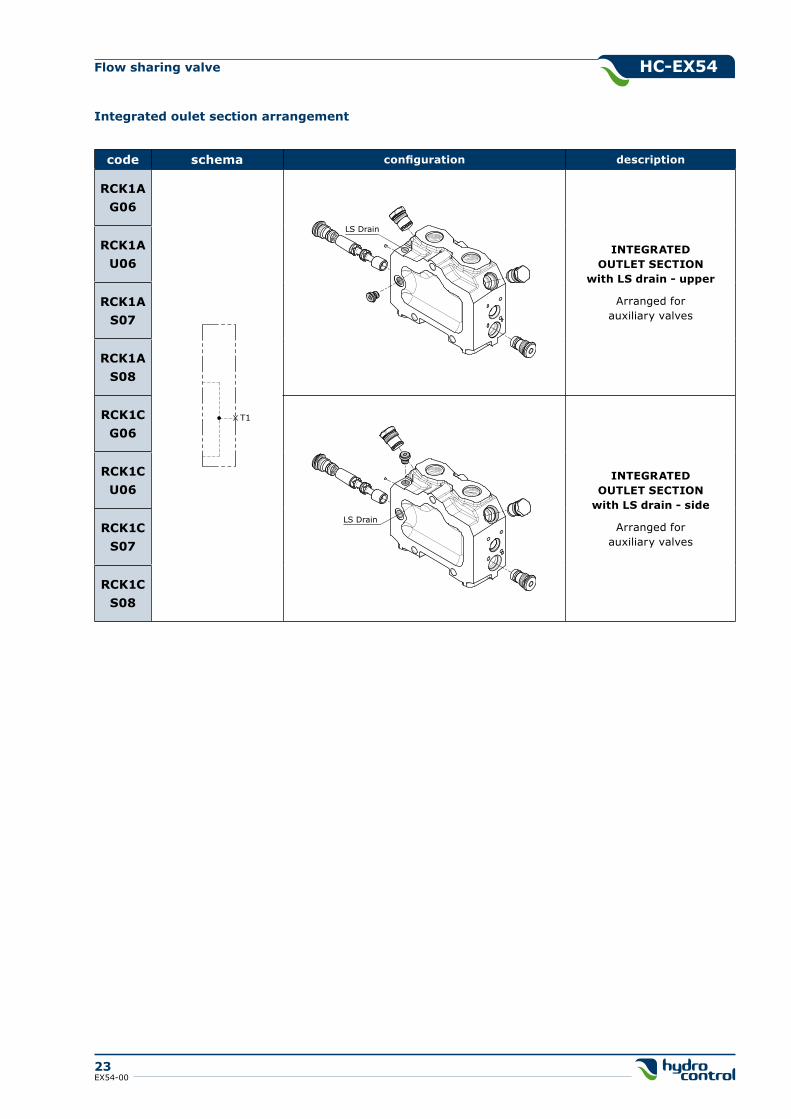
Integrated oulet section arrangement
code schema configuration description
RCk1Ag06
INTEgRATEDOUTLET SECTION
with LS drain - upper
Arranged forauxiliary valves
RCk1AU06
RCk1AS07
RCk1AS08
RCk1Cg06
INTEgRATEDOUTLET SECTION
with LS drain - side
Arranged forauxiliary valves
RCk1CU06
RCk1CS07
RCk1CS08
T1
LS Drain
LS Drain
hC-EX54
24EX54-00
Flow sharing valve
PT
4
B
A
B
A
1
11
9
10
5
6
12
7
8
2
1416
17
18
19
21
20
13
3
14*
15
15*
1416
17
13
15 19
18
14*
15*
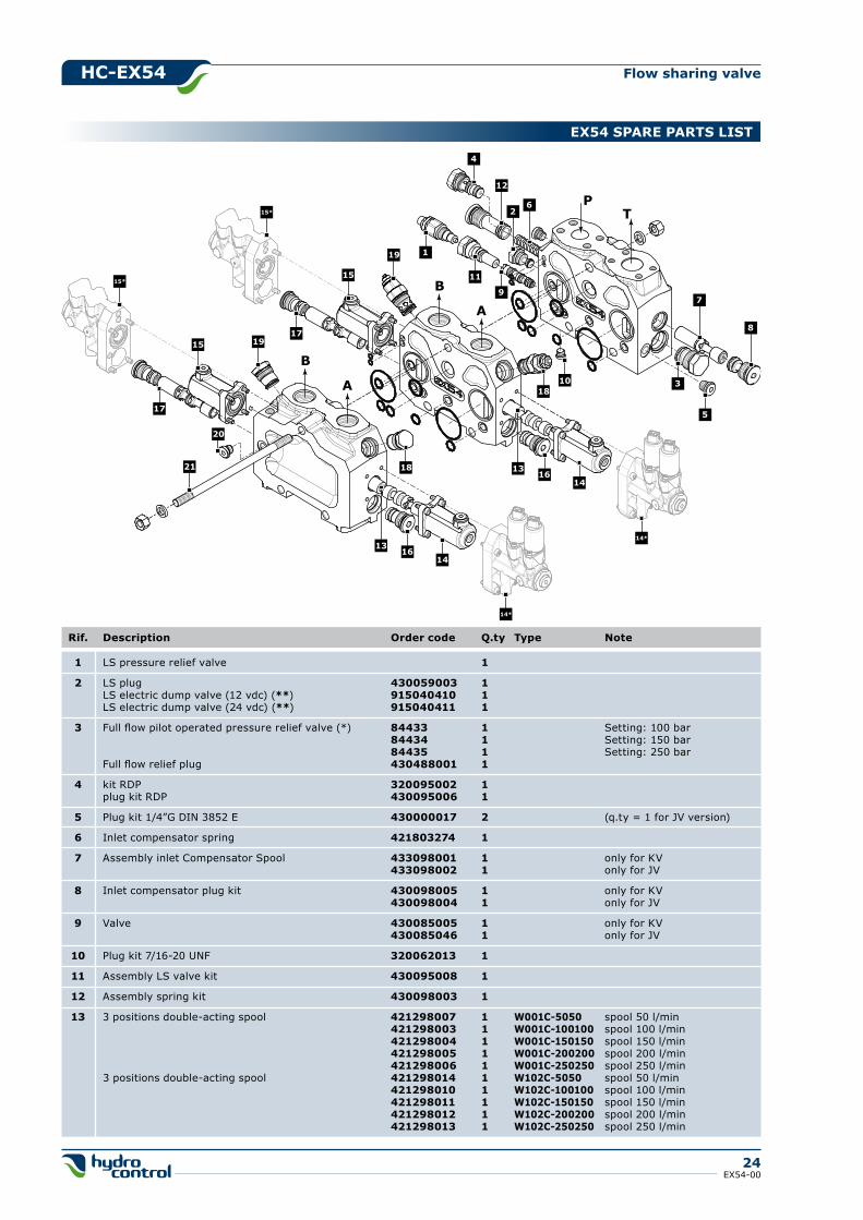
EX54 SPARE PARTS LIST
1 LS pressure relief valve 1
2 LS plug 430059003 1 LS electric dump valve (12 vdc) (**) 915040410 1 LS electric dump valve (24 vdc) (**) 915040411 1
3 Full flow pilot operated pressure relief valve (*) 84433 1 Setting: 100 bar 84434 1 Setting: 150 bar 84435 1 Setting: 250 bar Full flow relief plug 430488001 1
4 kit RDP 320095002 1 plug kit RDP 430095006 1
5 Plug kit 1/4”G DIN 3852 E 430000017 2 (q.ty = 1 for JV version)
6 Inlet compensator spring 421803274 1
7 Assembly inlet Compensator Spool 433098001 1 only for KV 433098002 1 only for JV
8 Inlet compensator plug kit 430098005 1 only for KV 430098004 1 only for JV
9 Valve 430085005 1 only for KV 430085046 1 only for JV
10 Plug kit 7/16-20 UNF 320062013 1
11 Assembly LS valve kit 430095008 1
12 Assembly spring kit 430098003 1
13 3 positions double-acting spool 421298007 1 W001C-5050 spool 50 l/min 421298003 1 W001C-100100 spool 100 l/min 421298004 1 W001C-150150 spool 150 l/min 421298005 1 W001C-200200 spool 200 l/min 421298006 1 W001C-250250 spool 250 l/min 3 positions double-acting spool 421298014 1 W102C-5050 spool 50 l/min 421298010 1 W102C-100100 spool 100 l/min 421298011 1 W102C-150150 spool 150 l/min 421298012 1 W102C-200200 spool 200 l/min 421298013 1 W102C-250250 spool 250 l/min
Rif. Description Order code Q.ty Type Note
hC-EX54
25EX54-00
Flow sharing valve
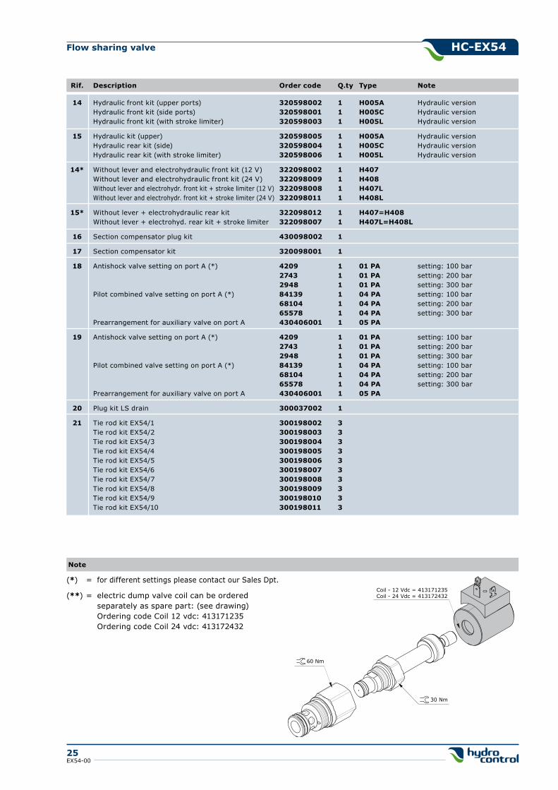
14 Hydraulic front kit (upper ports) 320598002 1 h005A Hydraulic version Hydraulic front kit (side ports) 320598001 1 h005C Hydraulic version Hydraulic front kit (with stroke limiter) 320598003 1 h005L Hydraulic version
15 Hydraulic kit (upper) 320598005 1 h005A Hydraulic version Hydraulic rear kit (side) 320598004 1 h005C Hydraulic version Hydraulic rear kit (with stroke limiter) 320598006 1 h005L Hydraulic version
14* Without lever and electrohydraulic front kit (12 V) 322098002 1 h407 Without lever and electrohydraulic front kit (24 V) 322098009 1 h408 Without lever and electrohydr. front kit + stroke limiter (12 V) 322098008 1 h407L Without lever and electrohydr. front kit + stroke limiter (24 V) 322098011 1 h408L
15* Without lever + electrohydraulic rear kit 322098012 1 h407=h408 Without lever + electrohyd. rear kit + stroke limiter 322098007 1 h407L=h408L
16 Section compensator plug kit 430098002 1
17 Section compensator kit 320098001 1
18 Antishock valve setting on port A (*) 4209 1 01 PA setting: 100 bar 2743 1 01 PA setting: 200 bar 2948 1 01 PA setting: 300 bar Pilot combined valve setting on port A (*) 84139 1 04 PA setting: 100 bar 68104 1 04 PA setting: 200 bar 65578 1 04 PA setting: 300 bar Prearrangement for auxiliary valve on port A 430406001 1 05 PA
19 Antishock valve setting on port A (*) 4209 1 01 PA setting: 100 bar 2743 1 01 PA setting: 200 bar 2948 1 01 PA setting: 300 bar Pilot combined valve setting on port A (*) 84139 1 04 PA setting: 100 bar 68104 1 04 PA setting: 200 bar 65578 1 04 PA setting: 300 bar Prearrangement for auxiliary valve on port A 430406001 1 05 PA
20 Plug kit LS drain 300037002 1
21 Tie rod kit EX54/1 300198002 3 Tie rod kit EX54/2 300198003 3 Tie rod kit EX54/3 300198004 3 Tie rod kit EX54/4 300198005 3 Tie rod kit EX54/5 300198006 3 Tie rod kit EX54/6 300198007 3 Tie rod kit EX54/7 300198008 3 Tie rod kit EX54/8 300198009 3 Tie rod kit EX54/9 300198010 3 Tie rod kit EX54/10 300198011 3
Rif. Description Order code Q.ty Type Note
Note
(*) = for different settings please contact our Sales Dpt.
(**) = electric dump valve coil can be ordered separately as spare part: (see drawing) Ordering code Coil 12 vdc: 413171235 Ordering code Coil 24 vdc: 413172432
60 Nm
30 Nm
Coil - 12 Vdc = 413171235Coil - 24 Vdc = 413172432
hC-EX54
26EX54-00
Flow sharing valve
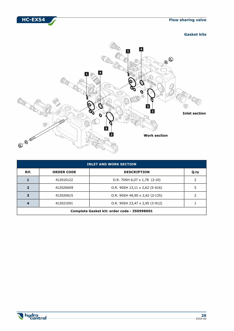
Inlet section
Work section
1
1
2
2
3
3
4
4
INLET AND WORk SECTION
Rif. ORDER CODE DESCRIPTION Q.ty
1 412010122 O.R. 70SH 6,07 x 1,78 (2-10) 2
2 412020609 O.R. 90SH 13,11 x 2,62 (5-616) 5
3 412020615 O.R. 90SH 48,90 x 2,62 (2-135) 2
4 412021001 O.R. 90SH 23,47 x 2,95 (3-912) 1
Complete gasket kit: order code - 350998001
gasket kits
hC-EX54
27EX54-00
Flow sharing valve
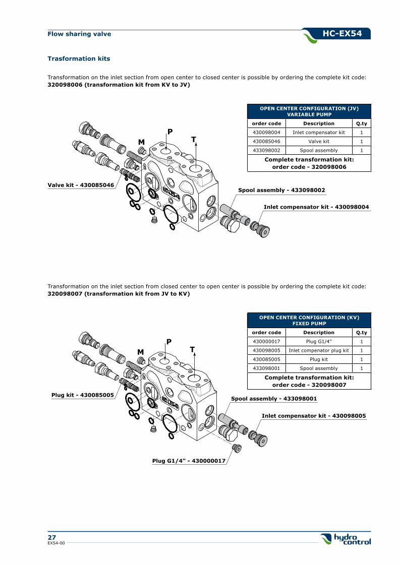
PTM
Spool assembly - 433098002Valve kit - 430085046
Inlet compensator kit - 430098004
PTM
Spool assembly - 433098001Plug kit - 430085005
Inlet compensator kit - 430098005
Plug G1/4” - 430000017
OPEN CENTER CONFIgURATION (kV)FIXED PUMP
order code Description Q.ty
430000017 Plug G1/4” 1
430098005 Inlet compenator plug kit 1
430085005 Plug kit 1
433098001 Spool assembly 1
Complete transformation kit:order code - 320098007
Transformation on the inlet section from open center to closed center is possible by ordering the complete kit code: 320098006 (transformation kit from kV to JV)
Transformation on the inlet section from closed center to open center is possible by ordering the complete kit code: 320098007 (transformation kit from JV to kV)
OPEN CENTER CONFIgURATION (JV)VARIABLE PUMP
order code Description Q.ty
430098004 Inlet compensator kit 1
430085046 Valve kit 1
433098002 Spool assembly 1
Complete transformation kit:order code - 320098006
Trasformation kits
hC-EX54
28EX54-00
Flow sharing valve
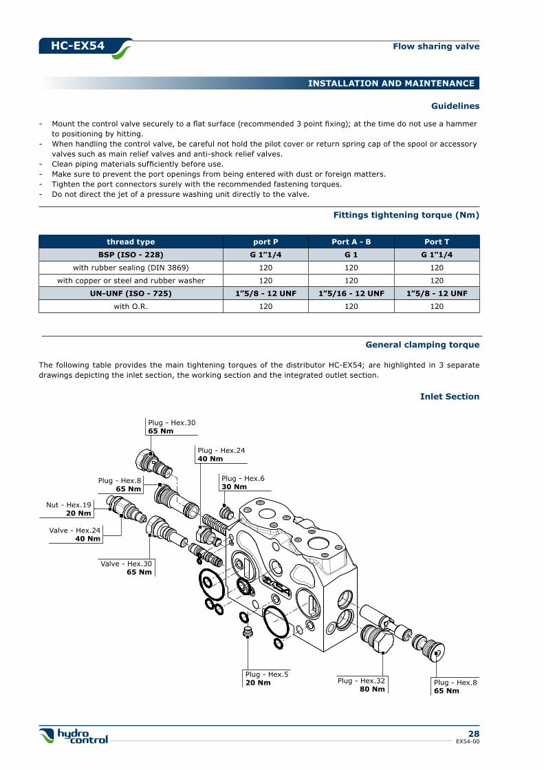
Plug - Hex.630 Nm
Plug - Hex.3280 Nm
Plug - Hex.520 Nm
Valve - Hex.3065 Nm
Plug - Hex.865 Nm
Nut - Hex.1920 Nm
Valve - Hex.2440 Nm
Plug - Hex.3065 Nm
Plug - Hex.2440 Nm
Plug - Hex.865 Nm
INSTALLATION AND MAINTENANCE
general clamping torque
The following table provides the main tightening torques of the distributor HC-EX54; are highlighted in 3 separate drawings depicting the inlet section, the working section and the integrated outlet section.
Inlet Section
Fittings tightening torque (Nm)
thread type port P Port A - B Port T
BSP (ISO - 228) g 1”1/4 g 1 g 1”1/4
with rubber sealing (DIN 3869) 120 120 120
with copper or steel and rubber washer 120 120 120
UN-UNF (ISO - 725) 1”5/8 - 12 UNF 1”5/16 - 12 UNF 1”5/8 - 12 UNF
with O.R. 120 120 120
guidelines
- Mount the control valve securely to a flat surface (recommended 3 point fixing); at the time do not use a hammer to positioning by hitting.- When handling the control valve, be careful not hold the pilot cover or return spring cap of the spool or accessory valves such as main relief valves and anti-shock relief valves.- Clean piping materials sufficiently before use.- Make sure to prevent the port openings from being entered with dust or foreign matters.- Tighten the port connectors surely with the recommended fastening torques.- Do not direct the jet of a pressure washing unit directly to the valve.
hC-EX54
29EX54-00
Flow sharing valve
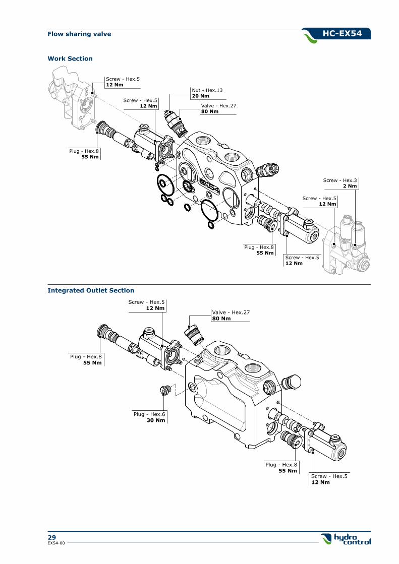
Work Section
Plug - Hex.855 Nm
Screw - Hex.512 Nm
Plug - Hex.855 Nm
Screw - Hex.512 Nm
Screw - Hex.32 Nm
Nut - Hex.1320 Nm
Valve - Hex.2780 Nm
Screw - Hex.512 Nm
Screw - Hex.512 Nm
Plug - Hex.855 Nm
Screw - Hex.512 Nm
Plug - Hex.855 Nm
Screw - Hex.512 Nm
Valve - Hex.2780 Nm
Plug - Hex.630 Nm
Integrated Outlet Section
Flow sharing valve
30EX54-00
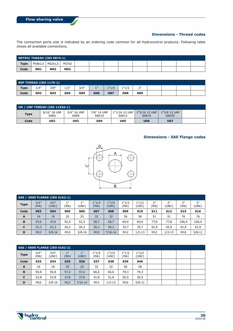
Dimensions - Thread codes
METRIC ThREAD (ISO 9974-1)
Type M18x1,5 M22x1,5 M27x2
Code M01 M02 M03
BSP ThREAD (ISO 1179-1)
Type 1/4” 3/8” 1/2” 3/4” 1” 1”1/4 1”1/2 2”
Code g02 g03 g04 g05 g06 g07 g08 g09
UN / UNF ThREAD (ISO 11926-1)
Type 9/16” 18 UNFSAE6
3/4” 16 UNFSAE8
7/8” 14 UNFSAE10
1”1/16 12 UNFSAE12
1”5/16 12 UNFSAE16
1”5/8 12 UNFSAE20
Code U02 U03 U04 U05 U06 U07
SAE / 3000 FLANgE (ISO 6162-1)
Type 3/4”(MA)
3/4”(UNC)
1”(MA)
1”(UNC)
1”1/4(MA)
1”1/4(UNC)
1”1/2(MA)
1”1/2(UNC)
2”(MA)
2”(UNC)
3”(MA)
3”(UNC)
Code S03 S04 S05 S06 S07 S08 S09 S10 S11 S12 S15 S16
A 19 19 25 25 32 32 38 38 51 51 76 76
B 47,6 47,6 52,4 52,4 58,7 58,7 69,9 69,9 77,8 77,8 106,4 106,4
C 22,3 22,3 26,2 26,2 30,2 30,2 35,7 35,7 42,9 42,9 61,9 61,9
D M10 3/8-16 M10 3/8-16 M10 7/16-14 M12 1/2-13 M12 1/2-13 M16 5/8-11
SAE / 6000 FLANgE (ISO 6162-2)
Type 3/4”(MA)
3/4”(UNC)
1”(MA)
1”(UNC)
1”1/4(MA)
1”1/4(UNC)
1”1/2(MA)
1”1/2(UNC)
Code S33 S34 S35 S36 S37 S38 S39 S40
A 19 19 25 25 32 32 38 38
B 50,8 50,8 57,2 57,2 66,6 66,6 79,3 79,3
C 23,8 23,8 27,8 27,8 31,8 31,8 36,5 36,5
D M10 3/8-16 M12 7/16-14 M14 1/2-13 M16 5/8-11
The connection ports size is indicated by an ordering code common for all Hydrocontrol products. Following table shows all available connections.
C
A
B
D
Dimensions - SAE Flange codes

Flow sharing valve
31EX54-00
Product identificationAll Hydrocontrol products have an identifying plate placed in specific position.
Serial number
Product code
Made in Italy
000807500
44612
Serial number
Product code
Serial number:It univocally identifies the physical valve: this provides an easy way to find all sales and production details.
Product code:It is a number univocally identifying the configuration and pressure settings of a valve.
Introduction
These general conditions apply to all general supplies from Hydrocontrol s.p.a., after receiving orders from the Custo-mer. Should commercial terms such as EXW, DDP, etc be mentioned, of course the Incoterms of the International Cham-ber of Commerce must be referred to, according to the test existing when the general supply conditions are agreed on.
Management of orders
No Customer’s order is binding to Hydrocontrol s.p.a. if Hydrocontrol s.p.a. has not confirmed the order in writing. Hydrocontrol s.p.a. commits to supplying the orders in compliance with the order confirmation that has been is-sued. Any disagreement with the content of the order confirmation must be communicated in writing to Hydrocon-trol s.p.a. within and no later than 5 days from the delivery of the order confirmation. The Customer commits to paying for the goods supplied by Hydrocontrol s.p.a., according to the prices indicated on the order confirmation.
Payment conditions
The Parties agree on the payment terms at the beginning of the supply. The terms will be indicated on the order con-firmation. Should the Customer be late with the payments, Hydrocontrol S.p.a. will be entitled to require the payment of interests on arrears based on the exiting Prime Rate increased by 2%. Should there be any payment delay, Hydro-control s.p.a. will be entitled not to process the Customer’s purchase order, even if it has already been confirmed.
Delivery and shipment
The goods are always supplied Ex Works, even when Hydrocontrol s.p.a. agrees with the Customer that the shi-pment, or a part of it, will be arranged by Hydrocontrol s.p.a. It is agreed that the Customer will bear the risk of goods deterioration or damaging from the moment the goods are handed by Hydrocontrol s.p.a. to the first carrier.
Product characteristics
Hydrocontrol s.p.a. commits to supplying good quality products, compliant with the technical specifications declared on the technical tables and on the catalogue. Hydrocontrol s.p.a, even without notice, at its own discretion, reserves the right to modify the products as necessary, without these changes altering the main characteristics of the products.
Claims
Any claims about defects on delivered products (just as an example: claims about the packaging, the number, the quantity or the external product characteristics) will have to be notified to Hydrocontrol s.p.a. in writing, within and no later than 7 days from reception of the goods, otherwise the claims will be considered as null and void. Occult defects (the defects of the goods that cannot be spotted with a careful control of the goods received by the Customer), will have to be notified in writing to Hydrocontrol s.p.a. within 7 days from the discovery of the defect, and anyhow no later than 12 months from the delivery of the goods, otherwise the claim will be consi-dered as null and void. Even in case of claim or objection, the Customer will never be entitled to suspend or de-lay the payments to Hydrocontrol s.p.a. for the products subject to claim or objection nor for any other supply.
gENERAL CONDITIONS AND PATENTS
Flow sharing valve
32EX54-00
gENERAL CONDITIONS AND PATENTS
Warranty
Should the products supplied by Hydrocontrol not be compliant or have the required quality and should this defect be due to Hydrocontrol, Hydrocontrol s.p.a. commits, at its choice, to replace or repair the faulty products, as long as the defect or lack of compliance is notified to Hydrocontrol s.p.a. in writing, as specified at point 6, within and no later than 18 months from product delivery. On the products that have been fixed or replaced in accordance with what specified above, the above-mentioned warranty applies. The 12 month duration starts from the date of repair or replacement. In case of defects, lack of quality or in case of lack of compliance for the supplied products, with the exception of fraud or serious offence, Hydrocontrol s.p.a. only commits to repairing or replacing the faul-ty products, according to what specified above. This warranty replaces any other Supplier’s warranty or liability established by the law. This warranty excludes any other liability contractual or extra-contractual by Hydrocontrol s.p.a. on the products supplied by Hydrocontrol (as a mere example: damage refund, loss of profit, product recall campaign, etc). Hydrocontrol s.p.a. has signed a product civil liability police, with a suitable maximum coverage.
Ownership retention
The products supplied by Hydrocontrol s.p.a. will be owned by the latter until Hydrocontrol receives the complete payment for the supplied goods.
Obligation confidentiality
Hydrocontrol s.p.a. commits to not disclosing the technical and commercial information it receives from the Customer, unless this information has already been publicly disclosed.
Patents
The Customer is not allowed to use the provided Products, or a part of them, their descriptions or drawings protected or not protected by Patent or registered trademark in order to design or make similar products, unless Hydrocontrol s.p.a. previously issues its written authorization. Should Hydrocontrol s.p.a. give its written authorization, all patents, trade-marks, registered designs, copyrights and intellectual property rights related or connected to the Products provided by Hydrocontrol s.p.a. will stay Hydrocontrol’s property. The Customer commits to respecting the highest confidentiality.
Applicable law and court of jurisdiction
Hydrocontrol s.p.a.’s supplies are regulated by these General Supply Conditions and, for anything not defi-ned here, by the Italian law. Any controversy related, generated or connected to the supply of Products by Hydrocontrol s.p.a., where Hydrocontrol s.p.a. is involved, will be exclusively dealt with by the Court of Bologna.
HC-EX54Flow sharing compensated valve
A global partner for innovative solutions
www.hydrocontrol-inc.com
HEAD QUARTERSHydrocontrol SpAVia San Giovanni 481 . 40060 Osteria GrandeCastel S.Pietro Terme . Bologna - ItalyPhone +39.051.6959411 (15 linee)Fax +39.051.946476Phone sales Dep.: +39.051.6959447Fax sales Dep.: [email protected]
U.S.A.Hydrocontrol Inc.1109 Technology Drive . Red Wing, MN 55066 U.S.APhone +1 (651) 212 6400 . Fax +1 (651 212 6401)usa@hydrocontrol-inc-com
GERMANYHydrocontrol GmbHRudolf Diesel Str. 1 42477 RadevormwaldDeutschlandPhone +49 2195-931123 Fax +49 [email protected]
FRANCEHC France SAS7, Rue des Entrepreneurs . Parc de la Vertonne44122 Vertou . FrancePhone +33 02-40332348 . Fax +33 [email protected]
EX54-00 04.2013
INDIAHC Hydraulic Technologies (P) LTDA5 (B) Ngef Ancillary Indl. EstateWhitefield Road . Mahadevpura (Po)Bangalore . 560048IndiaPhone +91 (080) 40454707 Fax +91 (080) [email protected]
CHINAHC China Sales and Production FacilityGuangzhou Bushi Hydraulic Technology LtdShangwei Shaheshe, Yuehu VillageXiancun, Xintang Town . Zengcheng City511335 Guangzhou . Guangdong ProvinceChinaPhone +86 (021) 52380695Fax +86 (021) 52380697fareast@hydrocontrol-inc-com