hc-14 nexstar owners manual - auto...
TRANSCRIPT

470103110-HC-14-NS-0315-A
HC-14 NEXSTAR
OWNERS MANUAL
Serial No. __________________
Mailing Address: P.O. Box 580697 Tulsa, OK 74158-0697 Physical Address: 4707 N. Mingo Rd. Tulsa, OK 74117-5904
Phone 1-800-777-2760 Fax (918) 269-6688 http://www.autocrane.com


Product Registration Rev 05152014
Auto Crane Registration
From: Date:
End User Information:
Company: Phone:
Address:
City: State: Zip:
Contact: E-mail:
Distributor Information:
Company: Phone:
Address:
City: State: Zip:
Contact: E-mail:
Product Information:
Model No: Serial No: Date Delivered:
VIN #:
ONE REGISTRATION FORM PER UNIT (CRANE, BODY, OR COMPRESSOR)Please submit form within 15 days after installation
Online: www.autocrane.com | Resources | Warranties
Fax: 918-234-2177
Mail: Product Registration, Auto Crane Company, PO Box 580697, Tulsa, OK 74158-0697


READ THIS PAGE
WARNING! Federal law (49 cfr part 571) requires that the Final Stage Manufacturer of a vehicle certify that the vehicle complies with all applicable federal regulations. Any modi!cations performed on the vehicle prior to the !nal state are also considered intermediate stage manufacturing and must be certi!ed as to compliance. "e installer of this crane and body is considered one of the manufacturers of the vehicle. As such a manufacturer, the installer is responsible for compliance with all applicable federal and state regulations, and is required to certify that the vehicle is in compliance.
WARNING! It is the further responsibility of the installer to comply with the OSHA Truck Crane Stability Requirements as speci!ed by 29 CFR part 1910.180 (C) (1).
WARNING! NEVER OPERATE THE CRANE NEAR ELECTRICAL POWER LINES!
Death or serious injury will result from boom, line, or load contacting electric lines. Do not use crane within 10 feet (3.05m) of electric power lines carrying up to 50,000 volts. One-foot additional clearance is required for every additional 30,000 volts or less. SEE DANGER DECAL (P/N 040529) in this Owner’s Manual.
WARNING! NEVER .....................................................
EXCEED load chart capacities (centerline of rotation to hoist hook).
Un-reel last 5 wraps of cable from drum!
Wrap cable around load!
Attempt to li$ or drag a load from the side! "e boom can fail far below its rated capacity.
Weld, modify, or use unauthorized components on any Auto Crane unit! "is will void any warranty or liability. Also failure of the crane may result.
Place a chain link on the tip of the hook and try to li$ a load!
Use a sling bar or anything larger than the hook throat that could prevent the hook latch from closing, thus negating the safety feature!
Hold on any pendant Select Switch that will cause unsafe operating conditions!
WARNING! In using a hook with latch, ALWAYS make sure that the hook throat is closed before li$ing a load! Proper attention and common sense applied to the use of the hoist hook and various slings will prevent possible damage to material being hoisted and may prevent injury to personnel.
WARNING! Failure to correctly plumb and wire crane can cause inadvertent operation and damage to crane and/or personnel!
WARNING! Auto Crane Company remote controlled cranes are not designed or intended for use for any applications involving the li$ing or moving of personnel.
WARNING! ALWAYS operate the crane in compliance with the load capacity chart. DO NOT USE the overload shutdown device to determine maximum rated loads, if the crane is equipped with this type of device.
WARNINGS

HC-14 NEXSTARTABLE OF CONTENTS
INTRODUCTION ……………………………………………………………… 1
GENERAL SPECIFICATIONS ……………………………………………………………… 3
SAFETY TIPS AND PRECAUTIONS ……………………………………………………………… 4
OPERATING PRACTICES & WARNINGS ……………………………………………………………… 6
QUALIFICATIONS FOR OPERATORS ……………………………………………………………… 7
OPERATION OF UNIT / OUTRIGGERS ……………………………………………………………… 10
CRANE OPERATION ……………………………………………………………… 11-13
TRASMITTER SYNCHRONIZATION ……………………………………………………………… 14
INSPECTION ……………………………………………………………… 15
TESTING ……………………………………………………………… 17
MAINTENANCE ……………………………………………………………… 19
BATTERIES ……………………………………………………………… 21
LUBRICATION AND MAINTENANCE SCHEDULE……………………………………………………………… 23
ROTATION BEARING ……………………………………………………………… 25
SAFETY DECAL SECTION ……………………………………………………………… 26
GENERAL DIMENSIONS ……………………………………………………………… 33
MOUNTING AND INSTALLATION ……………………………………………………………… 35
GENERAL ASSEMBLY, HARDWIRED ……………………………………………………………… 37
PEDESTAL ASSEMBLY ……………………………………………………………… 39
BOOM ASSEMBLY ……………………………………………………………… 44
ROTATION GEAR BOX ……………………………………………………………… 46
HOIST ASSEMBLY ……………………………………………………………… 48
TRAVELING BLOCK ASSEMBLY ……………………………………………………………… 51
MAIN HARNESS ……………………………………………………………… 52
HYDRAULIC SECTION ……………………………………………………………… 53
COUNTER BALANCE VALVE ADJUSTMENT ……………………………………………………………… 55
TROUBLE SHOOTING CHART ……………………………………………………………… 57
CARTRIDGE MAINTENANCE ……………………………………………………………… 63
LOAD CHART ……………………………………………………………… 64
PREVENTATIVE MAINTENANCE ……………………………………………………………… 65
WA RRANTY ……………………………………………………………… LAST 2 PAGES

1
HC-14 NEXSTAR INTRODUCTION
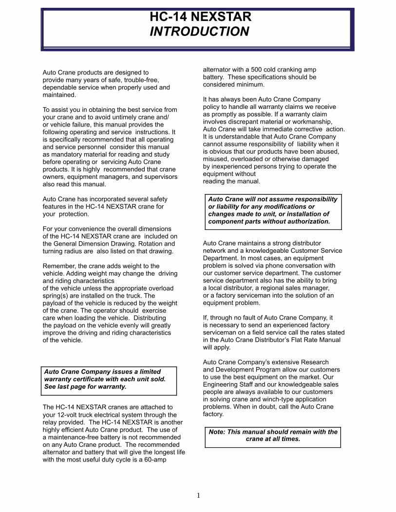
alternator with a 500 cold cranking amp battery. These specifications should be considered minimum. It has always been Auto Crane Company policy to handle all warranty claims we receive as promptly as possible. If a warranty claim involves discrepant material or workmanship, Auto Crane will take immediate corrective action. It is understandable that Auto Crane Company cannot assume responsibility of liability when it is obvious that our products have been abused, misused, overloaded or otherwise damaged by inexperienced persons trying to operate the equipment without reading the manual.
Auto Crane maintains a strong distributor network and a knowledgeable Customer Service Department. In most cases, an equipment problem is solved via phone conversation with our customer service department. The customer service department also has the ability to bring a local distributor, a regional sales manager, or a factory serviceman into the solution of an equipment problem.
If, through no fault of Auto Crane Company, it is necessary to send an experienced factory serviceman on a field service call the rates stated in the Auto Crane Distributor’s Flat Rate Manual will apply.
Auto Crane Company’s extensive Research and Development Program allow our customers to use the best equipment on the market. Our Engineering Staff and our knowledgeable sales people are always available to our customers in solving crane and winch-type application problems. When in doubt, call the Auto Crane factory.
Auto Crane will not assume responsibility or liability for any modifications or changes made to unit, or installation of component parts without authorization.
Note: This manual should remain with the crane at all times.
Auto Crane products are designed to provide many years of safe, trouble-free, dependable service when properly used and maintained. To assist you in obtaining the best service from your crane and to avoid untimely crane and/or vehicle failure, this manual provides the following operating and service instructions. It is specifically recommended that all operating and service personnel consider this manual as mandatory material for reading and study before operating or servicing Auto Crane products. It is highly recommended that crane owners, equipment managers, and supervisors also read this manual. Auto Crane has incorporated several safety features in the HC-14 NEXSTAR crane for your protection. For your convenience the overall dimensions of the HC-14 NEXSTAR crane are included on the General Dimension Drawing. Rotation and turning radius are also listed on that drawing. Remember, the crane adds weight to the vehicle. Adding weight may change the driving and riding characteristics of the vehicle unless the appropriate overload spring(s) are installed on the truck. The payload of the vehicle is reduced by the weight of the crane. The operator should exercise care when loading the vehicle. Distributing the payload on the vehicle evenly will greatly improve the driving and riding characteristics of the vehicle.
The HC-14 NEXSTAR cranes are attached to
your 12-volt truck electrical system through the relay provided. The HC-14 NEXSTAR is another highly efficient Auto Crane product. The use of a maintenance-free battery is not recom mended on any Auto Crane product. The rec ommended alternator and battery that will give the longest life with the most useful duty cycle is a 60-amp
Auto Crane Company issues a limited warranty certificate with each unit sold. See last page for warranty.

2
HC-14 NEXSTAR INTRODUCTION
DISTRIBUTOR ASSISTANCE:
Should you require any assistance not given in this manual, we recommend that you consult your nearest Auto Crane Distributor. Our distributors sell authorized parts and have service departments that can solve almost any needed repair. This manual does not cover all maintenance, operating, or repair instructions pertinent to all possible situations. If you require additional information, please contact the Auto Crane Company at the following tele phone number: 1-800-777-2760. The information contained in the manual is in effect at the time of this printing. Auto Crane Company reserves the right to update this material without notice or obligation.
3
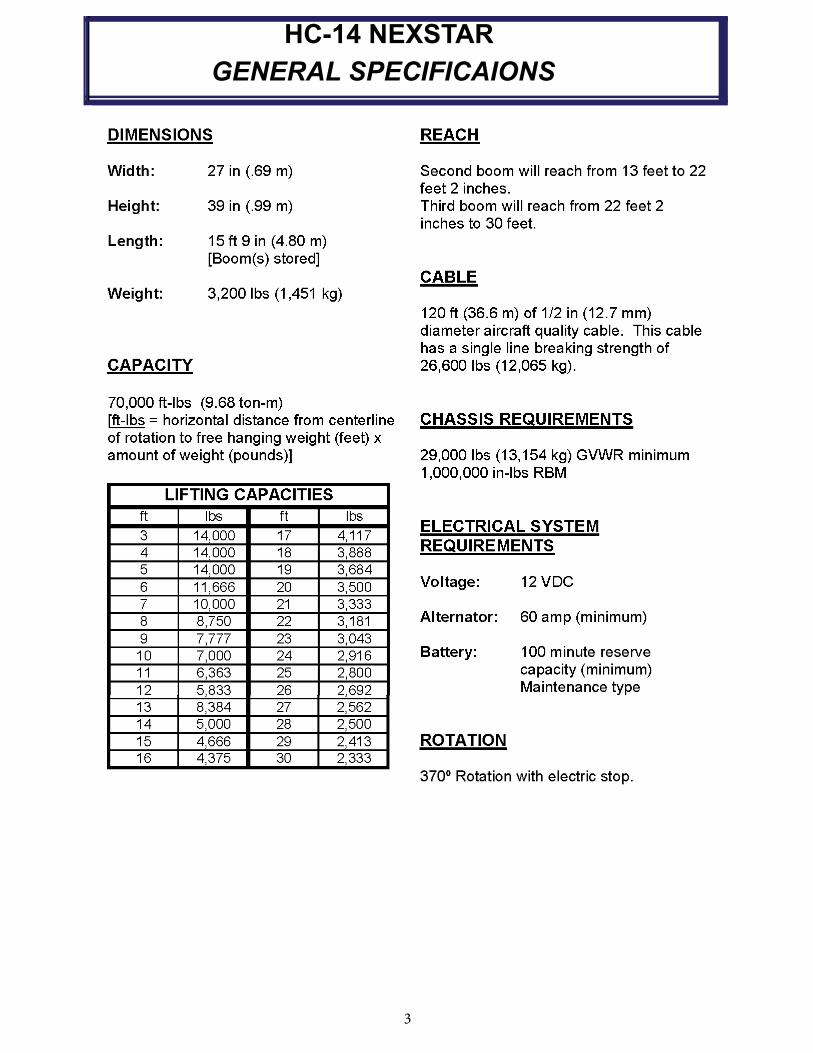
HC-14 NEXSTAR
GENERAL SPECIFICAIONS

4
-IMPORTANT-
SAFETY TIPS AND PRECAUTIONS
1. No unqualified or unauthorized person shall be allowed to operate the crane.
2. WARNING: Never weld, modify, or use unau-thorized components / parts on any Auto Crane unit. This will void any warranty or liability. Also, failure of the crane may result.
3. Make certain the vehicle meets minimum chassis requirements. (These requirements do not guarantee unit stability.)
4. Make certain the crane is installed per factory specifications. Contact your local distributor or the Auto Crane factory if any questions arise.
5. Visual inspections and tests should be con-ducted at the beginning of each shift each day to insure that the crane and all its operat ing systems are in good condition and work ing order before it is used.
6. Inspect hydraulic hoses frequently for signs of deterioration, and replace them as re quired.
7. If a hydraulic break occurs, leave the area of the break and do not attempt to stop the break by hand as the hydraulic oil may be hot and under high pressure which can cause serious injury. Shut the system down as soon as possible.
8. Check the hook at least every thirty days for distortions or cracks and replace it as re quired.
9. Oil gears as required.
10. Stop all operations when cleaning, adjusting or lubricating the machine.
11. Keep dirt and grit out of moving parts by keeping crane clean. Make sure machine is free of excess oil, grease, mud and rubbish, thus reducing accidents and fire hazards.
12. When a new cable is installed, operate first with a light load to let the cable adjust itself.
13. Locate the vehicle at the work site for the best stability possible.
14. Keep the vehicle in a level position while loading or unloading.
15. Observe operating area for obstructions and/ or power lines that might be a hazard.
16. WARNING: NEVER OPERATE THE CRANE NEAR ELECTRICAL POWER LINES. Auto Crane Company recommends that the crane never be any closer to a power line (including telephone lines) than 10 feet at any point.
17. Allow the vehicle engine to warm up before operating crane.
18. Know the weight of your rigging and load to avoid overloading the crane.
19. Deduct the weight of the load handling equip-ment from the load rating to determine how much weight can be lifted.
20. All load ratings are based on crane capacity, NOT the vehicle stability. Remember in lifting a heavy load, the weight can create enough tipping moment to overturn the vehicle
21. Always comply with load chart capacities, (centerline of rotation to hook).
22. Secure all loads before lifting.
23. Always set the emergency brake before begin-ning operation.
24. Keep objects and personnel clear of crane path during operation.
25. Operate control levers slowly and smoothly in order to meter oil flow for safe operation.
(Not applicable to electric-hydraulic cranes.)
26. Always extend the outriggers from vehicle to the ground before crane operation. Insure that they are firmly positioned on solid foot ings. Stand clear of outriggers while they are being extended.
27. If any outrigger, when extended, rests on a curb or other object that prevents it from ex tending to its maximum distance, shorten bearing or fulcrum point and reduce the maxi-mum load accordingly.
28. When an outrigger will not reach the ground due to holes or grades, it shall be blocked up to provide level and firm support for the truck.
29. When working in soft earth, use wide pads under outrigger feet to prevent sinking.
30. Always store outriggers before transportation.
WARNING!
Auto Crane Company cranes are not designed or intended for use in lifting or moving persons. Any such use shall be considered to be improper and the seller shall not be responsible for any claims arising there from. This sale is made with the express understanding that there is no warranty that the goods shall be fit for the purpose of lifting or moving persons or other improper use and there is no implied warranty or responsibility for such purposes.
5
-IMPORTANT- SAFETY TIPS AND PRECAUTIONS
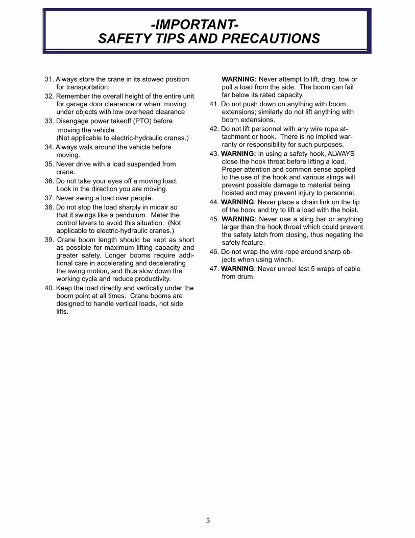
31. Always store the crane in its stowed position for transportation.
32. Remember the overall height of the entire unit for garage door clearance or when moving under objects with low overhead clearance
33. Disengage power takeoff (PTO) before
moving the vehicle. (Not applicable to electric-hydraulic cranes.)
34. Always walk around the vehicle before moving.
35. Never drive with a load suspended from crane.
36. Do not take your eyes off a moving load. Look in the direction you are moving.
37. Never swing a load over people.
38. Do not stop the load sharply in midair so that it swings like a pendulum. Meter the control levers to avoid this situation. (Not applicable to electric-hydraulic cranes.)
39. Crane boom length should be kept as short as possible for maximum lifting capacity and greater safety. Longer booms require addi-tional care in accelerating and deceleratingthe swing motion, and thus slow down the working cycle and reduce productivity.
40. Keep the load directly and vertically under the boom point at all times. Crane booms are designed to handle vertical loads, not side lifts.
WARNING: Never attempt to lift, drag, tow or pull a load from the side. The boom can fail far below its rated capacity.
41. Do not push down on anything with boom extensions; similarly do not lift anything with boom extensions.
42. Do not lift personnel with any wire rope at-tachment or hook. There is no implied war-ranty or responsibility for such purposes.
43. WARNING: In using a safety hook, ALWAYS close the hook throat before lifting a load. Proper attention and common sense applied to the use of the hook and various slings will prevent possible damage to material being hoisted and may prevent injury to personnel.
44. WARNING: Never place a chain link on the tip of the hook and try to lift a load with the hoist.
45. WARNING: Never use a sling bar or anything larger than the hook throat which could pre vent the safety latch from closing, thus negat ing the safety feature.
46. Do not wrap the wire rope around sharp ob-jects when using winch.
47. WARNING: Never unreel last 5 wraps of ca ble from drum.
6
-IMPORTANT-
OPERATING PRACTICES AND WARNINGS
1. Make certain the vehicle meets minimum chassis requirements. (These requirements do not guarantee unit stability)
2. Make certain the crane is installed per factory specifications. Contact your local Distributor or the Auto Crane factory if any questions arise.
3. Keep the vehicle in as level a position as possible while loading or unloading.
4. ALWAYS set the vehicle emergency brake before beginning crane operations.
5. ALWAYS use outriggers from vehicle to the ground during crane operation. Make sure they are firmly positioned on solid footings.
6. All load ratings are based on crane capacity, NOT truck/crane stability.
7. Keep objects and personnel clear of crane path during operation.
8. Keep hoist cable pulled tight at all times.
9. REMEMBER, in lifting a heavy load, the weight can create enough tipping momentum to overturn the vehicle.
10. ALWAYS keep load as close to ground as possible.
11. Hydraulic hoses need to be inspected frequently for signs of deterioration, and be replaced as required.
12. The hoist hook is an important item that an operator should consider and use properly. It should be checked on a daily basis for distortion or cracks.
13. ALWAYS store outriggers before road travel.
14. In applications, where the rotation of the load is haz-ardous, a tag or restraint line should be used (ref. OSHA 1910.180(h)(3)(xvi)). To reduce the potential for the load to rotate or rope twist, operate at mini mal boom angles and extension. If restraining the load and/or changing operation location is not an option, Contact AutoCrane for rotation resistant wire rope for your application.
14. WARNING! NEVER OPERATE THE CRANE NEAR ELECTRICAL POWER LINES! Death or serious injury will result from boom, line, or load contacting electric lines. Do not use crane within 10 feet (3.05m) of electric power lines carrying up to 50,000 volts. One foot additional clearance is required for every additional 30,000 volts or less.
15. WARNING! NEVER EXCEED load chart capacities (centerline of rotation to hoist hook).
16. WARNING! NEVER un-reel last 5 wraps of cable from drum!
17. WARNING! NEVER wrap cable around load!
18. WARNING! NEVER attempt to lift or drag a load from the side! The boom can fail far below its rated capacity.
19. WARNING! NEVER weld, modify, or use unauthorized components on any Auto Crane unit! This will void any warranty or liability. Also failure of the crane may result.
20. WARNING! NEVER place a chain link on the tip of the hook and try to lift a load!
21. WARNING! NEVER use a sling bar or anything larger than the hook throat that could prevent the hook latch from closing, thus negating the safety feature!
22. WARNING! In using a hook with latch, ALWAYS insure that the hook throat is closed before lifting a load! Proper attention and common sense ap plied to the use of the hoist hook and variousslings will prevent possible damage to material being hoisted and may prevent injury to personnel.
WARNING! NEVER hold any Control Select Switch on that will cause unsafe operating conditions!
WARNING! Auto Crane Company remote controlled, stiff boom cranes
are not designed or intended for use on any applications involving the lifting or moving of personnel.
7
QUALIFICATIONS FOR AND CONDUCT OF OPERATORS AND OPERATING PRACTICES
REFERENCE ASME B30.5a AND OSHA 1910.180 FOR COMPLETE QUALIFICATION
REQUIREMENTS
OPERATORS
1. Crane operation shall be limited to personnel with the following minimum qualifications:
A. Designated persons.
B. Trainees under the direct supervision of a designated person.
C. Maintenance and test personnel (when it is necessary in the performance of their du ties).
D. Inspectors (crane).
2. No one other than the personnel specified above shall enter the operating area of a crane with the exception of persons such as oilers, supervisors, and those specified persons authorized by supervisors whose duties require them to do so and then only in the performance of their duties and with the knowledge of the operator or other persons.
QUALIFICATIONS FOR OPERATORS
1. Operators shall be required by the employer to pass a practical operating examination. Qualifications shall be limited to the specific type of equipment for which examined.
2. Operators and operator trainees shall meet the following physical qualifications:
A. Vision of at least 20/30 Snellen in one eye and 20/50 in the other, with or without corrective lenses.
B. Ability to distinguish colors, regardless of position, if color differentiation is required for operation.
C. Adequate hearing with or without hearing aid for the specific operation.
3. Evidence of physical defects or emotional instability, which render a hazard to operator or others, which in the opinion of the examiner could interfere with the operator!s performance, may be sufficient cause for disqualification. In such cases, specialized clinical or medical judgment and tests may be required.
4. Evidence that operator is subject to seizures or loss of physical control shall be sufficient reason for disqualification. Specialized medical
tests may be required to determine these conditions.
5. Operators and operator trainees should have normal depth perception, coordination, and no tendencies to dizziness or similar undesirable characteristics.
6. In addition to the above listed requirements, the operator shall:
A. Demonstrate the ability to comprehend and interpret all labels, operator!s manuals, safety codes, and other information perti nent to correct crane operations.
B. Posses the knowledge of emergency proce-dures and implement it.
C. Demonstrate to the employer the ability to operate the specific type of equipment.
D. Be familiar with the applicable safety regula-tions.
E. Understand the operating procedures as out-lined by the manufacturer.
F. Be thoroughly familiar with the crane and its control functions.
G. Understand the operating procedures as outlined by the manufacturer.
CONDUCT OF OPERATORS
1. The operator shall not engage in any practice, which will divert his attention while actually oper-ating the crane.
2. Each operator shall be responsible for those operations under the operator’s direct control. Whenever there is any doubt as to safety, the operator shall consult with the supervisor before handling the loads.
3. The operator should not leave a suspended load unattended unless specific precautions have been instituted and are in place.
4. If there is a warning sign on the switch or engine starting controls, the operator shall not close the switch or start the engine until the warning signhas been removed by the appointed person.
5. Before closing the switch or starting the engine, the operator shall see that all controls are in the “OFF”

8
QUALIFICATIONS FOR AND CONDUCT OF OPERATORS AND OPERATING PRACTICES
or neutral position and all personnel are in the clear.
6. If power fails during operation, the operator shall:
A. Move power controls to the “OFF” or neu-tral position.
B. Land the suspended load and boom, if practical.
7. The operator shall be familiar with the equip-ment and its proper care. If adjustments or repairs are necessary, the operator shall re port the same promptly to the appointed per son, and shall also notify the next operator.
8. The operator at the start of each shift shall test all controls. If any controls do not operate properly, they shall be adjusted or repaired before operations are begun.
9. Stabilizers shall be visible to the operator while extending or setting unless a signal person assists operator.
OPERATING PRACTICES/HANDLING THE LOAD
1. Size of load.
A. No crane shall be loaded beyond the rated load except for test purposes
B. The load to be lifted is to be within the rated load of the crane and its existing configuration.
C. When loads that are not accurately known are to be lifted, the person responsible for the job shall ascertain that the weight ofthe load does not exceed the crane rated load at the radius at which the load is to be lifted.
2. Attaching the load.
A. The load shall be attached to the hook by means of slings or other devices of sufficient capacity.
B. Hoist rope shall not be wrapped around the load.
3. Moving the load.
The operator shall determine that:
A. The crane is level and, where necessary, the vehicle/carrier is blocked properly.
B. The load is well secured and balanced in the sling or lifting device before it is lifted more than a few inches.
C. Means are provided to hold the vehicle stationary while operating the crane.
D. Before starting to lift, the hook shall be positioned over the load in such a manner as to minimize swinging.
E. During lifting care shall be taken that:
1. There is no sudden acceleration or deceleration of the moving load.
2. Load, boom or other parts of the crane do not contact any obstruction.
F. Cranes shall not be used for dragging loads sideways.
G. This standard recognizes that telescopic boom cranes are designed and intended for handling materials. They do not meet personnel lift or elevator requirements. Therefore, no lifting, lowering, swinging or traveling shall be done while a person is on the hook or load. Hook attached suspended work platforms (baskets) shall not be used with cranes covered by this standard. Crane manufacturer must approve work platforms attached to the boom.
H. The operator should avoid carrying loads over people.
I. When the crane is so equipped, the stabilizers shall be fully extended and set. Blocking under stabilizers shall meet the requirements as follows:
1. Strong enough to prevent crushing.
2. Of such thickness, width and length as to completely support the stabilizer pad.
J. Firm footing under all tires, or individual stabilizer pads should be level. Where such a footing is not otherwise supplied, timbers, cribbing, or other structural members to distribute the load so as to not exceed allowable bearing capacity or the underlying material should provide it.
K. In transit, the boom shall be carried in stowed position.
L. When rotating the crane, sudden starts and stops shall be avoided. Rotational speed shall be such that the load does not swing out beyond the radius at which it can be controlled.
M. The crane shall not be transported with a load on the hook unless recommended by the manufacturer.
9
QUALIFICATIONS FOR AND CONDUCT OF OPERATORS AND OPERATING PRACTICES
N. No person should be permitted to stand or pass under a suspended load.
4. Stowing procedure.
Follow the manufacturer's procedure and sequence when stowing and un-stowing the crane.
MISCELLANEOUS
OPERATING NEAR ELECTRICAL POWER
LINES
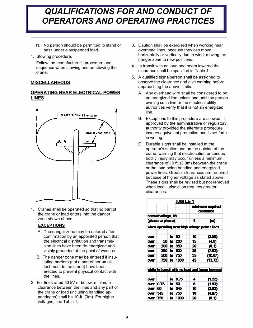
1. Cranes shall be operated so that no part of the crane or load enters into the danger zone shown above.
EXCEPTIONS
A. The danger zone may be entered after confirmation by an appointed person that the electrical distribution and transmis-sion lines have been de-energized and visibly grounded at the point of work; or
B. The danger zone may be entered if insu-lating barriers (not a part of nor an at-tachment to the crane) have been erected to prevent physical contact with the lines.
2. For lines rated 50 kV or below, minimum clearance between the lines and any part of the crane or load (including handling ap-pendages) shall be 10-ft. (3m). For higher voltages, see Table 1.
3. Caution shall be exercised when working near overhead lines, because they can move horizontally or vertically due to wind, moving the danger zone to new positions.
4. In transit with no load and boom lowered the clearance shall be specified in Table 1.
5. A qualified signalperson shall be assigned to observe the clearance and give warning before approaching the above limits.
A. Any overhead wire shall be considered to be an energized line unless and until the person owning such line or the electrical utility authorities verify that it is not an energized line.
B. Exceptions to this procedure are allowed, if approved by the administrative or regulatory authority provided the alternate procedure insures equivalent protection and is set forth in writing.
C. Durable signs shall be installed at the operator's station and on the outside of the crane, warning that electrocution or serious bodily injury may occur unless a minimum clearance of 10 ft. (3.0m) between the crane or the load being handled and energized power lines. Greater clearances are required because of higher voltage as stated above. These signs shall be revised but not removed when local jurisdiction requires greater clearances.
10
-IMPORTANT- BEFORE OPERATING CRANE
1. Make sure this manual has been thoroughly read by all crane operating personnel and supervisors.
2. A routine inspection of the crane should be mandatory before each operating day. Any defects should be corrected immediately.
3. At a job site the vehicle should be positioned so that the crane can adequately reach the load within the rated capacity (centerline of rotation to hoist hook).
4. Keep the vehicle as level as possible during
operation. CANNOT EXCEED 10° SLOPE.
5. For electric cranes, engage emergency brake and leave ignition on with transmission in neutral (or in park for automatic transmissions). Activate any crane power switches. For Auto Crane units requiring battery and hydraulic operation, engage emergency brake, place gear selector in neutral, press clutch, activate PTO, release clutch and after hydraulic fluid is warm, set throttle control to proper engine speed.
6. Always use outriggers from the truck to the
ground. Be sure these are firm and ade quately
positioned. When rotating, keep load as low
to the ground as possible.
7. Remove the transmitter from cab or storage area. Power transmitter on. Detach hook from dead man. Crane is now ready for op eration.
8. Always boom up before rotating so the boom will clear the required boom support.
9. When extending the boom, always maintain clearance between the boom crown and the traveling block or hoist hook.
10. Always observe safe and practical operation to avoid possible accidents. Refer to Safety Tips and Precautions.
11. After completing lifting operations, return the boom to stowed position on the boom support. Avoid unneeded pressure on the boom support.
12. Store transmitter in proper location (in cab or storage area).
13. Return outriggers to stowed position. Make sure they are pinned in place or jacklegs are returned to compartment.
14. Check work area for any tools or equipment not stored.
15. Release throttle control, depress clutch and dis-engage PTO. Deactivate any crane power switches.
16. Report any unusual occurrence during crane operation that may indicate required mainte-nance or repair.
17. NEVER use two cranes to support a load too large for either crane.
HYDRAULIC OUTRIGGERS1. Shift crane/outrigger control valve to
“outrigger” position.
2. Operate the outrigger control valves to position the outriggers.
3. After outriggers are positioned, return crane/ outrigger selector to “crane” position.
4. Crane is now ready to operate.
MANUAL OUTRIGGERS1. Pull lock pins to release jackleg or drop down
outrigger and move to outermost lock position.
2. Make sure lock pins are reinstalled properly.
3. Lower outrigger pad to firm ground and adjust foot to take out slack.
4. Crane is now ready to operate.
OPERATION OF OUTRIGGERS
11
CRANE OPERATION
BOOM DOWN BOOM UP
BELT CLIP
ENGINE STOP
(NEXSTAR II)
ENGINE FAST IDLE
(NEXSTAR II)
BOOM RETRACT
ENG ENG
STOP START
IDLE
FASTAUX
ENGINE START
(NEXSTAR II)
AUXILIARY
(NEXSTAR II)
HOIST DOWN
ROTATE CW
HOIST UP
BOOM EXTEND
ROTATE CCW
E-STOP SWITCH
MECHANICAL LATCHING
(TWIST TO UNLOCK)
SPEED
OFF
ON
ON/OFF/MULTI SPEED
3 POSITION KEYSWITCH
LED INDICATORS
%57%52 %001%05
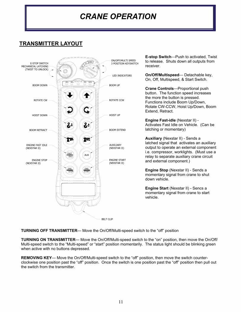
TRANSMITTER LAYOUT
E-stop Switch—Push to activated, Twist to release. Shuts down all outputs from receiver.
On/Off/Multispeed— Detachable key, On, Off, Multispeed, & Start Switch.
Crane Controls—Proportional push button. The function speed increases the more the button is pressed. Functions include Boom Up/Down, Rotate CW-CCW, Hoist Up/Down, Boom Extend, Retract.
Engine Fast-idle (Nexstar II) - Activates Fast Idle on Vehicle. (Can be latching or momentary)
Auxiliary (Nexstar II) - Sends a latched signal that activates an auxiliary output to operate an external component i.e. compressor, worklights. (Must use a relay to separate auxiliary crane circuit and external component.)
Engine Stop (Nexstar II) - Sends a momentary signal from crane to shut down vehicle.
Engine Start (Nexstar II) - Sencs a momentary signal from crane to start vehicle.
TURNING OFF TRANSMITTER— Move the On/Off/Multi-speed switch to the “off” position
TURNING ON TRANSMITTER— Move the On/Off/Multi-speed switch to the “on” position, then move the On/Off/Multi-speed switch to the “Multi-speed” or “start” position momentarily. The status light should be blinking green when active with no buttons depressed.
REMOVING KEY— Move the On/Off/Multi-speed switch to the “off” position, then move the switch counter-clockwise one position past the “off” position. Once the switch is one position past the “off” position then pull out the switch from the transmitter.

12
CRANE OPERATION
ACTIVATING E-STOP
Press the E-stop Switch.
Note:1. When E-stop is active, the transmitter will remain on but will not operate any functions. This includes truck
and crane functions. 2. Activating E-stop will not turn the truck off.3. There will be an Error Code on the receiver stating “E-stop active”.
DEACTIVATING E-STOP
1. Twist to release E-stop. 2. Turn transmitter to the “OFF” position. 3. Once all lights turn off. Turn transmitter to the “ON” postion. 4. Turn transmitter to the “START”/”SPEED” position and release
Note:There is very little height difference in a active and inactive E-stop. To verify E-stop switch is deactivated, twist switch to release.
WAKING UP TRANSMITTER
Turn the transmitter to the “START”/”SPEED” position and release
Note:The transmitter goes into sleep mode after 5 minutes of inactivity. All truck functions are still available and will remain in the same state. (i.e. Aux function will remain on even when the unit goes to sleep if it was active before unit went to sleep.)
SPEED CONTROL
1. Rotate “ON/OFF/SPEED” switch to the “SPEED” position and hold 2. Press the Boom Up switch in increase max speed or press Boom Down button to decrease. Each time the
button is actuated, the max speed increases or decreases to the next 25% range. 3. Release “ON/OFF/SPEED” switch once the desired speed is selected.
Note:1. Slower speed decreases the max speed and gives more finite control of the proportional push button. 2. Faster speed increases the max speed but give less finite control of the load 3. The LED indicators show the current speed setting of the transmitter.
ON/OFF/MULTI SPEED
3 POSITION KEYSWITCH
LED INDICATORS
25% 75%50% 100%
E-STOP SWITCH
MECHANICAL LATCHING
(TWIST TO UNLOCK)
OFF
ON
DECREASE MAX
SPEED
INCREASE MAX
SPEED
SPEED
13
CRANE OPERATION
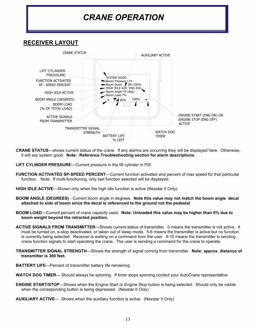
RECEIVER LAYOUT
CRANE STATUS—shows current status of the crane. If any alarms are occurring they will be displayed here. Otherwise, it will say system good. Note: Reference Troubleshooting section for alarm descriptions.
LIFT CYLINDER PRESSURE—Current pressure in the lift cylinder in PSI
FUNCTION ACTIVATED SP-SPEED PERCENT—Current function activated and percent of max speed for that particular function. Note: If multi-functioning, only last function selected will be displayed.
HIGH IDLE ACTIVE—Shown only when the high idle function is active (Nexstar II Only)
BOOM ANGLE (DEGREES) - Current boom angle in degrees. Note this value may not match the boom angle decal attached to side of boom since the decal is referenced to the ground not the pedestal.
BOOM LOAD—Current percent of crane capacity used. Note: Unloaded this value may be higher than 0% due to boom weight beyond the retracted position.
ACTIVE SIGNALS FROM TRANSMITTER—Shows current status of transmitter. 0 means the transmitter is not active. It must be turned on, e-stop deactivated, or taken out of sleep mode. 5-6 means the transmitter is active but no function is currently being selected. Receiver is waiting on a command from the user. 9-10 means the transmitter is sending crane function signals to start operating the crane. The user is sending a command for the crane to operate.
TRANSMITTER SIGNAL STRENGTH—Shows the strength of signal coming from transmitter. Note: approx. distance of transmitter is 300 feet.
BATTERY LIFE—Percent of transmitter battery life remaining
WATCH DOG TIMER— Should always be spinning. If timer stops spinning contact your AutoCrane representative
ENGINE START/STOP—Shows when the Engine Start or Engine Stop button is being selected. Should only be visible when the corresponding button is being depressed. (Nexstar II Only)
AUXILIARY ACTIVE— Shows when the auxiliary function is active. (Nexstar II Only)
80%9
CRANE STATUS
HIGH IDLE ACTIVE
BOOM ANGLE (DEGREES)
BOOM LOAD
(% OF TOTAL LOAD)
TRANSMITTER SIGNAL
STRENGTHBATTERY LIFE
% LEFT
100%
WATCH DOG
TIMER
FUNCTION ACTIVATED
SP - SPEED PERCENT
ENGINE START (ENG ON) OR
ENGINE STOP (ENG OFF)
ACTIVE
SYSTEM GOODBoom Pressure 174Boom Down SP=100%HIGH IDLE AUX ENG XXXBoom Angle 43 (deg)Boom Load 7%
AUXILIARY ACTIVE
ACTIVE SIGNALS
FROM TRANSMITTER
LIFT CYLINDER
PRESSURE
14
TRANSMITTER SYNCHRONIZATION
INSTRUCTIONS
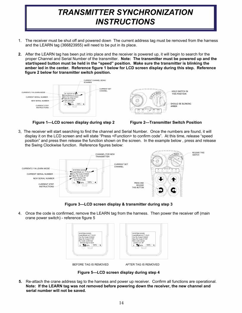
1. The receiver must be shut off and powered down The current address tag must be removed from the harness and the LEARN tag (366823955) will need to be put in its place.
2. After the LEARN tag has been put into place and the receiver is powered up, it will begin to search for the proper Channel and Serial Number of the transmitter. Note: The transmitter must be powered up and the start/speed button must be held in the “speed” position. Make sure the transmitter is blinking the
amber led in the center. Reference figure 1 below for LCD screen display during this step. Reference figure 2 below for transmitter switch position.
Figure 1—LCD screen display during step 2 Figure 2—Transmitter Switch Position
3, The receiver will start searching to find the channel and Serial Number. Once the numbers are found, it will display it on the LCD screen and will state “Press <Function> to confirm code”. At this time, release “speed position” and press then release the function shown on the screen. In the example below , press and release the Swing Clockwise function. Reference figures below:
Figure 3—LCD screen display & transmitter during step 3
4. Once the code is confirmed, remove the LEARN tag from the harness. Then power the receiver off (main crane power switch) - reference figure 5
Figure 5—LCD screen display during step 4
5. Re-attach the crane address tag to the harness and power up receiver. Confirm all functions are operational. Note: If the LEARN tag was not removed before powering down the receiver, the new channel and
serial number will not be saved.
S0. ESTOP ACTIVELearnMode sc= 6 rf=21Cur Rx Code 010020New Rx Code 00Start transmitter for new code
100%80%9
CURRENTLY IN LEARN MODE
CURRENT SERIAL NUMBER
NEW SERIAL NUMBER
CURRENT STEP
INSTRUCTIONS
CURRENT CHANNEL BEING
SCANNED
CURRENT SET
CHANNELSPEED
OFF
ON
HOLD SWITCH IN
THIS POSITION
SHOULD BE BLINKING
AMBER
25% 75%50% 100%
100%80%9
CURRENTLY IN LEARN MODE
CURRENT SERIAL NUMBER
NEW SERIAL NUMBER
CURRENT STEP
INSTRUCTIONS
CURRENT SET
CHANNEL
CHANNEL FOR NEW
TRANSMITTER
SYSTEM GOODLearnMode sc= 7 rf=21Cur Rx Code 010020New Rx Code 01157Press Swing CW to confirm code
SPEED
ON
OFF
PRESS AND
RELEASE
THIS BUTTON
RELEASE THIS
SWITCH
100%80%9
SYSTEM GOODLearnMode sc= 7 rf=21Cur Rx Code 010020New Rx Code 01157Rx Code confirmed remove tag to save
SYSTEM GOODLearnMode sc= 7 rf=21Cur Rx Code 010020New Rx Code 01157New code saved power rcvr off
100%80%9
BEFORE TAG IS REMOVED AFTER TAG IS REMOVED
15
INSPECTION REQUIREMENTS
REFERENCE ASME B30.5a AND OSHA 1910.180 FOR COMPLETE INSPECTION REQUIREMENTS
INSPECTION CLASSIFICATION
1. Initial inspection.
Prior to initial use, all new, altered, modified or extensively repaired cranes shall be inspected by a designated person to insure compliance with provisions of this standard
1. Regular inspection.
Inspection procedure for cranes in regular service is divided into two general classifications based upon the intervals at which inspection should be performed. The intervals in turn are dependent upon the nature of the components of the crane and the degree of their exposure to wear, deterioration, or malfunction. The two general classifications are herein designated as “frequent” and “periodic” with respective intervals between inspections as defined below.
A. Frequent inspection - daily or before each use
B. Periodic inspection - one to twelve-month intervals or as specifically recommended by the manufacturer or qualified person.
DESIGNATED PERSONNEL SHALL
PERFORM INSPECTIONS ONLY.
FREQUENT INSPECTION
Inspections should also occur during operation for any deficiencies that might appear between regular in-spections. Any deficiencies, such as those listed below, shall be carefully examined and a determination made as to whether they constitute a hazard:
1. Inspect control mechanisms for maladjustment that interferes with proper operation.
2. Inspect control mechanisms for excessive wear of components and contamination by lubricants or other foreign matter.
3. Inspect safety devices for malfunction.
4. Visually inspect all hydraulic hoses, particularly those that flex in normal operation of crane func-tions.
5. Inspect hooks and latches for deformation, chemi-cal damage, cracks, and wear. Refer to ANSI/ ASME B30.10.
6. Inspect for proper rope reeving.
7. Inspect electrical wiring and components for malfunctioning, signs of excessive deterioration, dirt and moisture accumulation.
8. Inspect hydraulic system for proper oil level and leaks.
9. Inspect tires for recommended inflation pressure, cuts and loose wheel nuts.
10. Inspect connecting pins and locking device for wear damage and loose retaining bolts.
11. Inspect rope for gross damage, such as listed below, which may be an immediate hazard.
A. Distortion such as kinking, crushing, un-stranding, birdcaging, main strand displacement, or core protrusion. Loss of rope diameter in a short length or unevenness of outer strands should be replaced.
B. General corrosion.
C. Broken or cut strands.
D. Use care when inspecting sections of rapid deterioration around flange points, crossover points, and repetitive pickup points on drums.
E. Inspect number, distribution, and type of visible broken wires. Reference Rope Maintenance section in the owner"s manual.
Continued use of rope depends upon good judgment by a designated person in evaluating remaining strength in a used rope after allowance for deterioration disclosed by inspection. Continued rope operation depends upon this remaining strength.
PERIODIC INSPECTION
Any deficiencies, such as those listed below, shall be carefully examined and determination made as to whether they constitute a hazard:
1. Inspect for deformed, cracked or corroded members in the crane structure and entire boom.
2. Inspect for loose bolts, particularly mounting bolts.
3. Inspect for cracked or worn sheaves and drums.
4. Inspect for worn, cracked, or distorted parts such as pins, bearings, shafts, gears, rollers and devices.
5. Inspect for excessive wear on brake and clutch system parts and lining.
16
INSPECTION REQUIREMENTS
6. Inspect crane hooks for cracks.
7. Inspect travel steering, braking, and locking devices for malfunction.
8. Inspect for excessively worn or damaged tires.
9. Inspect hydraulic hose, fittings, and tubing for the following problems:
A. Evidence of leakage at the surface of the flexible hose or its junction with metal and coupling.
B. Blistering, or abnormal deformation to the outer covering of the hydraulic or pneumatic hose.
C. Leakage at threaded or clamped joints that cannot be eliminated by normal tightening or recommended procedures.
D. Evidence of excessive abrasion or scrubbing on the outer surface of a hose, rigid tube, or fitting. Means shall be taken to eliminate the interference of elements in contact or other-wise protect the components.
10. Inspect hydraulic pumps and motors for the following problems:
A. Loose bolts and fasteners.
B. Leaks at joints between sections.
C. Shaft seal leaks.
D. Unusual noises or vibrations.
E. Loss of operating speed.
F. Excessive heating of the fluid.
G. Loss of pressure.
11. Inspect hydraulic valves for the following problems:
A. Cracks in valve housing.
B. Improper return of spool to neutral position.
C. Leaks at spools or joints.
D. Sticking spools.
E. Failure of relief valves to attain or maintain correct pressure setting.
F. Relief valve pressure shall be checked as specified by the manufacturers.
12. Inspect hydraulic cylinders for the following problems:
A. Drifting caused by fluid leaking across piston.
B. Rod seals leaking.
C. Leaks at welding joints.
D. Scored, nicked, or dented cylinder rods.
E. Damaged case (barrel).
F. Loose or deformed rod eyes or connecting joints.
13. Inspect hydraulic filters for evidence of rubber particles on the filter elements indicating possible hose, O-ring, or other rubber component dete-rioration. Metal chips or pieces on the filter may denote failure in pumps, motors, or cylinders. Further inspection will be necessary to determine the origin of the problem before corrective action can be taken.
14. Inspect labels to confirm correct location and legi-bility. Reference decal layout in this manual for proper location of decals.
15. Rope Inspections need not be at equal calen-dar intervals and should be more frequent as the rope approaches the end of useful life. A qualified person shall inspect the wire rope based on such factors as:
A. Expected rope life as determined by experi-ence on the particular installation or similar installations.
B. Severity of environment.
C. Percentage of capacity lifts.
D. Frequency rates of operation.
E. Exposure to shock loads.
This inspection shall cover the entire length of the rope. Only the surface wires need to be in spected and no attempt should be made to open the rope. Any deterioration resulting in apprecia ble loss of original strength shall be noted and determination made as to whether use of the rope would constitute a hazard. A few notable deterioration points are listed below:
A. Reduction of rope diameter below nominal diameter due to loss of core support.
B. Internal or external corrosion.
C. Wear of outside wires.
D. Severly corroded, cracked, bent, worn, or improperly applied connections.
CRANES NOT IN REGULAR USE
A crane, which has been idle for a period of over one month or more, shall be given an inspection conform-ing to the “initial” and “regular” inspection require ments of this section.
INSPECTION RECORDS
Dated records of periodic inspection should be made on critical items such as brakes, crane hooks, rope, cylinders, and relief pressure valves.
17
TESTING REQUIREMENTS
REFERENCE ASME B30.5a AND OSHA 1910.180 FOR COMPLETE INSPECTION REQUIREMENTS
TESTING SHALL BE PERFORMED BY DESIGNATED PERSONNEL ONLY.
Prior to initial use, all new, altered, modified, or extensively repaired cranes shall be tested for compliance with the operational requirements of this crane.
Test requirements:
1. Test all functions to verify speed and operation.
2. Check that all safety devices are working properly.
3. Confirm operating controls comply with appropriate function labels.
4. Test loads shall not exceed 110% of the manufacturer’s load rating.
5. Written reports shall be maintained showing test procedures and confirming the adequacy of repairs

NOTES
19
REFERENCE ASME B30.5a AND OSHA 1910.180 FOR COMPLETE MAINTENANCE AND
REPAIR REQUIREMENTS
A preventative maintenance program should be establi-shed based on this section and all replacement partsshould be obtained from AutoCrane Company. For replacement parts contact your local authorized distributor.
MAINTENANCE PRECAUTIONS
1. Place crane where it will cause the least interference with other equipment or operations.
2. Verify all controls are in the “off” position and all operating features secured from inadvertent motion by brakes, pawls, or other means.
3. The means for starting the crane shall be rendered inoperative.
4. The boom should be secured in place before maintenance.
5. Relieve hydraulic oil pressure from all hydraulic circuits before loosening or removing hydraulic components.
6. Warning or “OUT OF ORDER” signs shall be placed on all crane controls.
7. After adjustments and repairs have been made, the crane shall not be returned to service until all guards have been reinstalled, trapped air removed from hydraulic system (if required), safety devices reactivated, and maintenance equipment removed.
ADJUSTMENTS AND REPAIRS
1. Any hazardous conditions disclosed by the inspec-tion requirements shall be corrected before opera-tion of crane is resumed. Only designated person nel shall do adjustments and repairs.
2. Adjustments shall be maintained to assure correct functioning of components, the following are examples:
A. Functional operating mechanism.
B. Safety devices.
C. Control systems.
3. Repairs or replacements shall be provided as needed for operation, the following are examples:
A. Critical parts of functional operating mechanisms which are cracked, broken, corroded, bent, or excessively worn.
B. Critical parts of the crane structure which are cracked, bent, broken, or excessively corroded.
C. Crane hooks showing cracks, damage, or corrosion shall be taken out of service. Repairs by welding are not recommended.
4. If bleeding the hydraulic system is required, run each crane function until smooth operation of that particular function is noticeable.
LUBRICATION
All moving parts of the crane, for which lubrication is specified, should be regularly lubricated per the manu-facturer’s recommendations and procedures. Reference Lubrication and Maintenance Schedule in this manual.
ROPE REPLACEMENT
No precise rules can be given for determination of the exact time for replacement of rope, since many variable factors are involved.
1. Conditions such as the following shall be reason for questioning continued use of the rope or increasing the frequency of inspection:
A. In running ropes, six randomly distributed bro-ken wires in one lay or three broken wires in one strand in one lay.
B. One outer wire broken at the contact point with the core of the rope structure and protrudes or loops out of the rope structure. Additional in-spection of this section is required.
C. Wear of one third of the original diameter of the outside individual wire.
D. Kinking, crushing, bird caging, or any other dam-age resulting in distortion of the rope structure.
E. Evidence of any heat damage from any cause.
F. Reduction from nominal diameter of more than1/64 in. (0.4mm) for diameters up to and includ-ing 5/16 in. (8 mm), 1/32 in. (0.8 mm) for diameter 3/8 in. (9.5 mm) to and including 1/2 in. (13 mm), 3/64 in. (1.2 mm) for diameter 9/16 in. (14.5 mm) to and including 3/4 in. (19 mm). 1/16 in. (1.6 mm) for diameter 7/8 in. (22 mm) to and including 11/8 in. (29 mm), 3/32 in. (2.4 mm) for diameters 11/4 in. (32 mm) to and including 11/2 in. (38 mm).
G. In standing ropes, more than two broken wires in one lay in sections beyond end connections or more than one broken wire at an end connection.
GENERAL
REPAIRS AND MAINTENANCE
20
GENERAL
REPAIRS AND MAINTENANCE
2. Replacement rope shall have a strength rating at least as great as the original rope furnished or recommended by AutoCrane. A rope manufac-turer, AutoCrane, or a qualified person shall specify any deviation from the original size, grade, or construction.
ROPE MAINTENANCE
1. Rope should be stored to prevent damage or deterioration.
2. Unreeling or uncoiling of rope shall be done as recommended by the rope manufacturer and with care to avoid kinking or inducing twist.
3. Before cutting a rope, seizing shall be placed on each side of the place where the rope is to be cut to prevent unlaying of the strands. On pre -formed rope, one seizing on each side of the cut is required. On non-preformed ropes of 7/8 in. (22 mm) diameter or smaller, two seizings on each side of the cut are required, and for non preformed rope 1 in. (25 mm) diameter or larger, three seizings on each side of the cut are required.
4. During installation care should be exercised to avoid dragging of the rope in the dirt or around objects that will scrape, nick crush or induce sharp bends in it.
5. Rope should be maintained in a well-lubricated condition. It is important that lubricant applied as a part of a maintenance program shall be com patible with the original lubricant and to this end the rope manufacturer should be consulted. Lu bricant applied shall be the type that does not hinder visual inspection. Those sections of rope that are located over sheaves or otherwise hid-den during inspection and maintenance proce-dures require special attention when lubricating rope. The object of rope lubrication is to reduce internal friction and to prevent corrosion.
6. When an operating rope shows greater wear or well-defined localized areas than on the remain-der of the rope, rope life can be extended in some cases by shifting the wear to different ar eas of the rope.

21
MAINTENANCE OF BATTERIES
Maintenance of Auto Crane unit batteries differs very little from the generally prescribed maintenance of any lead acid battery. All batteries must be kept properly charged, properly filled with water, and relatively clean.
Keep Properly Charged
Many things affect the proper charge to a battery, such as:
1. Regulator settings.
2. Proper tightness of belts on the alternator or generator.
3. Good, clean connections of all cables and wires at the following places:
a. Battery.
b. Regulator.
c. Starting motor.
d. Alternator or generator.
e. Ground connections (most im-portant).
It is of extreme importance to keep the battery as fully charged as possible without overcharging, especially when vehicles are left outside for ex tended periods in extremely cold climates. A battery can freeze. Freezing points for various specific gravities of acid are as follows:
Specific Gravity Freezing Temp.
(Corrected to 80ºF) Degrees F.
1.280 -90ºF
1.250 -62ºF
1.200 -16ºF
1.150 5ºF
1.100 19ºF
As shown, a half-charged battery (about 1.100 specific gravity) cannot stand for any length of time at 20ºF or it will freeze.
The main reason for keeping the battery as fully charged as possible without over-charging is to in-sure that power is available even though the vehicle has been standing for some time.
Keep Properly Filled with Water
The battery should always be properly filled with water. If the electrolyte level is allowed to fall below the top of the plates, the results become threefold:
1. The exposed portion of the plate will become sulfated.
2. The portion of the plate exposed is not usable.
3. That portion of the acid remaining becomes more concentrated and may cause more rapid deteriora-tion of the remaining parts of the battery.
Keep A Relatively Clean Battery
The battery should be kept clean. Batteries filled with acid and which are not in use self-discharge to a limited degree because of the nature of the materials within the battery. If dirt is allowed to collect on the top of the battery (and this dirt absorbs moisture) and electrical path can be set up between the various terminals of the battery and the ground. Once such a path has been established, the self-discharge of the battery is acceler-ated. This also accelerates corrosion of the battery cables at the terminals.
Periodic Maintenance is Needed
A definite program of periodic maintenance of all bat teries should be conducted on a regular basis. Peri odic maintenance includes:
1. Checking belts for tightness on the charging equip-ment.
2. Checking battery electrolyte levels.
3. Checking cables for good connections.
4. Cleaning where corrosion is apparent.
When corrosion is cleaned off, the cable terminals and battery terminals should be coated with a light coating of petroleum jelly before they are replaced. When ter-minals are cleaned, the top of the battery should becleaned with a mild solution of soda water.
Low Maintenance Batteries
(Maintenance Free)
Low maintenance batteries should not be used on AutoCrane Cranes or trucks equipped with Auto-Crane Cranes. The batteries are not designed for “deep” discharge.
Testing Your Battery
If the condition of the battery is in question, it should be removed from the vehicle, taken to the shop, and al lowed to reach room temperature. It should then berecharged until specific gravity readings taken at one-half hour intervals. If the specific gravity readings are fairly uniform, the battery should be checked with a high rate tester. Use the tester in accordance with the manufacturer’s instructions. The high rate tester is the best method to test a questionable battery.

22
MAINTENANCE OF BATTERIES
If, after charging, it is noted that the specific gravity
reading of one cell is 30 points less than any of the
other cells, it may be assumed that the cell is badand that the battery should be replaced. If all cells are uniform but not up to full charge, a low rate of charge should be attempted for an extended time. This usually will recover a badly sulfated battery.
Replacing a Battery
If it is necessary to replace a battery, and a dry
charge battery is used, the following procedure
applies:
1. Fill the battery with electrolyte of the proper
specific gravity.
2. Place the battery on charge according to the manufacturer’s instructions.
It is essential that the second step above be followed to ensure that the battery going on the vehicle is fully charged.
It is also very important that the battery hold-downs be
checked periodically to insure that the batteries are
properly positioned to avoid vibration problems,
breakage of cables or terminals. Care must be taken
to avoid cracking or breaking containers or covers by
tightening hold-down fixtures excessively. They also
must not be so loose that breakage results from a hold-
down that is too loose.
23
HC-14 NEXSTAR
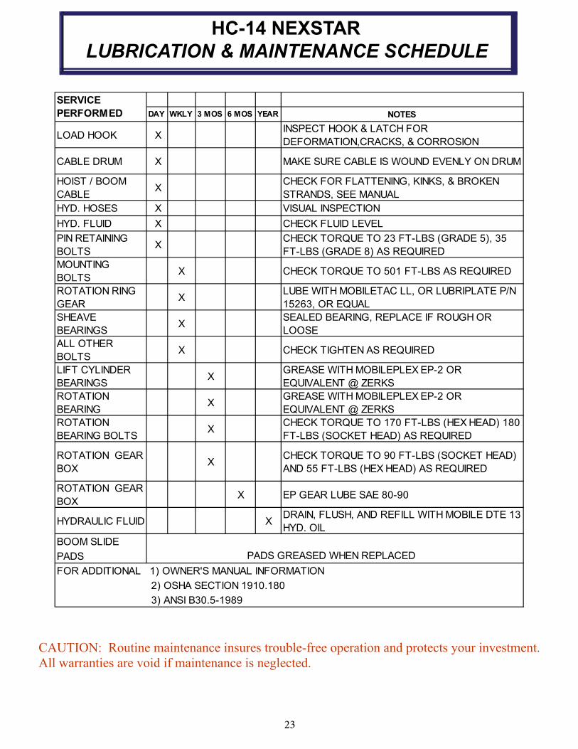
LUBRICATION & MAINTENANCE SCHEDULE
CAUTION: Routine maintenance insures trouble-free operation and protects your invest ment.
All warranties are void if maintenance is neglected.
DAY WKLY 3 MOS 6 MOS YEAR NOTES
LOAD HOOK XINSPECT HOOK & LATCH FOR
DEFORMATION,CRACKS, & CORROSION
CABLE DRUM X MAKE SURE CABLE IS WOUND EVENLY ON DRUM
HOIST / BOOM
CABLEX
CHECK FOR FLATTENING, KINKS, & BROKEN
STRANDS, SEE MANUAL
HYD. HOSES X VISUAL INSPECTION
HYD. FLUID X CHECK FLUID LEVEL
PIN RETAINING
BOLTSX
CHECK TORQUE TO 23 FT-LBS (GRADE 5), 35
FT-LBS (GRADE 8) AS REQUIRED
MOUNTING
BOLTSX CHECK TORQUE TO 501 FT-LBS AS REQUIRED
ROTATION RING
GEARX
LUBE WITH MOBILETAC LL, OR LUBRIPLATE P/N
15263, OR EQUAL
SHEAVE
BEARINGSX
SEALED BEARING, REPLACE IF ROUGH OR
LOOSE
ALL OTHER
BOLTSX CHECK TIGHTEN AS REQUIRED
LIFT CYLINDER
BEARINGSX
GREASE WITH MOBILEPLEX EP-2 OR
EQUIVALENT @ ZERKS
ROTATION
BEARINGX
GREASE WITH MOBILEPLEX EP-2 OR
EQUIVALENT @ ZERKS
ROTATION
BEARING BOLTSX
CHECK TORQUE TO 170 FT-LBS (HEX HEAD) 180
FT-LBS (SOCKET HEAD) AS REQUIRED
ROTATION GEAR
BOXX
CHECK TORQUE TO 90 FT-LBS (SOCKET HEAD)
AND 55 FT-LBS (HEX HEAD) AS REQUIRED
ROTATION GEAR
BOXX EP GEAR LUBE SAE 80-90
HYDRAULIC FLUID XDRAIN, FLUSH, AND REFILL WITH MOBILE DTE 13
HYD. OIL
BOOM SLIDE
PADS
FOR ADDITIONAL 1) OWNER'S MANUAL INFORMATION
2) OSHA SECTION 1910.180
3) ANSI B30.5-1989
PADS GREASED WHEN REPLACED
SERVICE
PERFORMED
24
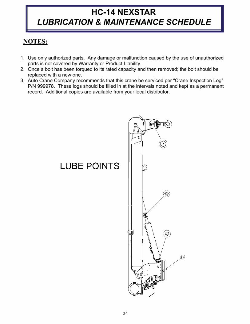
HC-14 NEXSTAR
LUBRICATION & MAINTENANCE SCHEDULE
4-9.0
1. Use only authorized parts. Any damage or malfunction caused by the use of unauthorized parts is not covered by Warranty or Product Liability.
2. Once a bolt has been torqued to its rated capacity and then removed; the bolt should bereplaced with a new one.
3. Auto Crane Company recommends that this crane be serviced per “Crane Inspection Log”P/N 999978. These logs should be filled in at the intervals noted and kept as a permanent record. Additional copies are available from your local distributor.
NOTES:

25
ROTATION BEARING REPLACEMENT
GUIDELINES—14005H
All bearings can wear over time. This includes the main rotation bearing on the crane. No pre-cise rules can be given for replacement of the rotation bearing, since many factors are in-volved. However, there are common symptoms seen during crane operation that may be caused by rotation bearing wear. These symptoms include: 1. Excessive Noise 2. Rough rotation 3. Increased drive power required to rotate. 4. Metal particles in grease
REASONS FOR ROTATION BEARING REPLACEMENT 1. Any noticeable cracking in the bearing housing 2. Damage to internal teeth 3. Excessive axial play (reference axial play check instructions below)
WARNING—NEVER TRY TO REPAIR A ROTATION BEARING. FOR A REPLACE-MENT BEARING CONTACT YOUR LOCAL AUTHORIZED DISTRIBUTOR.
AXIAL PLAY ALLOWANCE CHECK PROCEDURE 1. Boom up to the max boom angle and measure the clearance between base plate and the
rotation bearing with a dial or filler gauge. Reference figure 1 for location. 2. Boom down to the horizontal position and measure the clearance between the base plate
and the rotation bearing with a dial indicator or feeler gauge. Reference figure 1 for loca-tion.
3. If the difference between the two measurements exceeds 2.3mm, replace bearing. 4. Rotate crane 45 degrees then repeat steps above until you reach 360 degrees of rotation.
Rotation bearing replacement kit part number is 470001000
WARNING—WHEN REPLACING ROTATION BEARING, USE NEW HARDWARE WHICH IS INCLUDED IN THE KIT ABOVE.
HC-14 NEXSTAR

26
HC-14 NEXSTAR SAFETY DECAL SECTION
PART NO.: 040579000
DECAL: OPERATING INSTRUCTIONS
FUNCTION: To inform the operator of the proper
procedure to follow for safe operation
of the crane.
USED ON: All Cranes
QUANTITY: 1
PLACEMENT: Right side plate
PART NO.: 040580000
DECAL: OPERATING TRAINING
FUNCTION: To inform the operator of the need to
receive proper training before using
the crane.
USED ON: All Cranes
QUANTITY: 1
PLACEMENT: Right side plate
PART NO.: 040632000
DECAL: TAMPERING WITH OVERLOAD DEVICE
FUNCTION: To inform the operator that tampering
with the overload device may cause a
unit failure or possible personal injury.
USED ON: All Cranes equiped with a load sensor
QUANTITY: 1
PLACEMENT: Right side of valve sensor.

27
HC-14 NEXSTAR SAFETY DECAL SECTION
PART NO.: 040529000
DECAL: ELECTROCUTION HAZARD
FUNCTION: To inform the operator of the
hazard involved with contacting
electrical power lines with crane
boom.
USED ON: All Cranes
QUANTITY: 2
PLACEMENT: Both sides of end of lower boom
PART NO.: 040517000
DECAL: STAY CLEAR OF BOOM
FUNCTION: To inform the operator of the
hazard of proximity or contact
with the crane boom during
operation.
USED ON: All Cranes
QUANTITY: 2
PLACEMENT: Both sides of crown
PART NO.: 040518000
DECAL: STAY CLEAR OF LOAD
FUNCTION: To inform the operator of the
hazard of proximity or contact
with the crane load during
operation.
USED ON: All Cranes
QUANTITY: 2
PLACEMENT: Both sides of traveling block
28
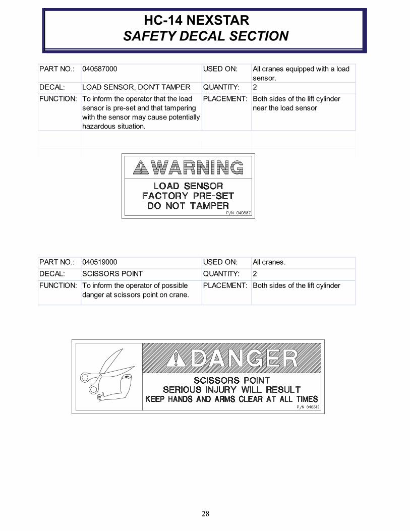
HC-14 NEXSTAR
SAFETY DECAL SECTION
daol a htiw deppiuqe senarc llA:NO DESU000785040:.ON TRAP
sensor.
DECAL: LOAD SENSOR, DON'T TAMPER QUANTITY: 2
FUNCTION: To inform the operator that the load
sensor is pre-set and that tampering
with the sensor may cause potentially
hazardous situation.
PLACEMENT: Both sides of the lift cylinder
near the load sensor
.senarc llA:NO DESU000915040:.ON TRAP
DECAL: SCISSORS POINT QUANTITY: 2
FUNCTION: To inform the operator of possible
danger at scissors point on crane.
PLACEMENT: Both sides of the lift cylinder

29
HC-14 NEXSTAR
SAFETY DECAL SECTION
MF htiw depiuqe senarC llA:NO DESU000961064:.ON TRAP
controls.
DECAL: REMOTE CONTROL QUANTITY: 1
FUNCTION: To inform the operator of failure to
follow the saftey precautions may
result in equipment failure or serious
personal injury.
PLACEMENT: LEFT SIDE OF PLATE
REMOTE CONTROL SAFETY PRECAUTIONS
READ THE OPERATOR'S MANUAL before using the Remote Control System.
Failure to follow the safety precautions may result in equipment failure or serious
personal injury.
MAKE SURE MACHINERY AND SUROUNDING AREA IS CLEAR BEFORE
OPERATING REMOTE CONTROL SYSTEM. Do not activate the Remote Control
System unless it is safe to do so.
TURN OFF THE RECEIVER POWER BEFORE WORKING ON THE MACHINE.
Always disconnect the Remote Control System before doing any maintenance to
prevent accidental operation of the machine.
DO NOT MODIFY EQUIPMENT WITHOUT WRITTEN APPROVAL FROM THE
MANUFACTURER.
CARE
KEEP DRY. Do not clean the Transmitter / Receiver under high pressure. If water
or other liquids get inside the Transmitter battery or Receiver compartment,
immediately dry the unit. Remove the case and let the unit air dry.
Clean the unit after operation using a damp cloth to remove any mud, dirt, concrete,
etc. from the unit and prevent clogging of buttons, switches, etc.
MAINTENANCE / WELDING
DISCONNECT THE RECEIVER BEFORE WELDING ON THIS MACNINE. Failure
to disconnect will result in the destruction of the Receiver.
WARNING

NOTES

31
HC-14 NEXSTAR DECAL LAYOUT P/N: 470103021
3 4
5
12
9
8
1716
10
7
13
15
6
2
14
1
11
SECTION A-A
18
32
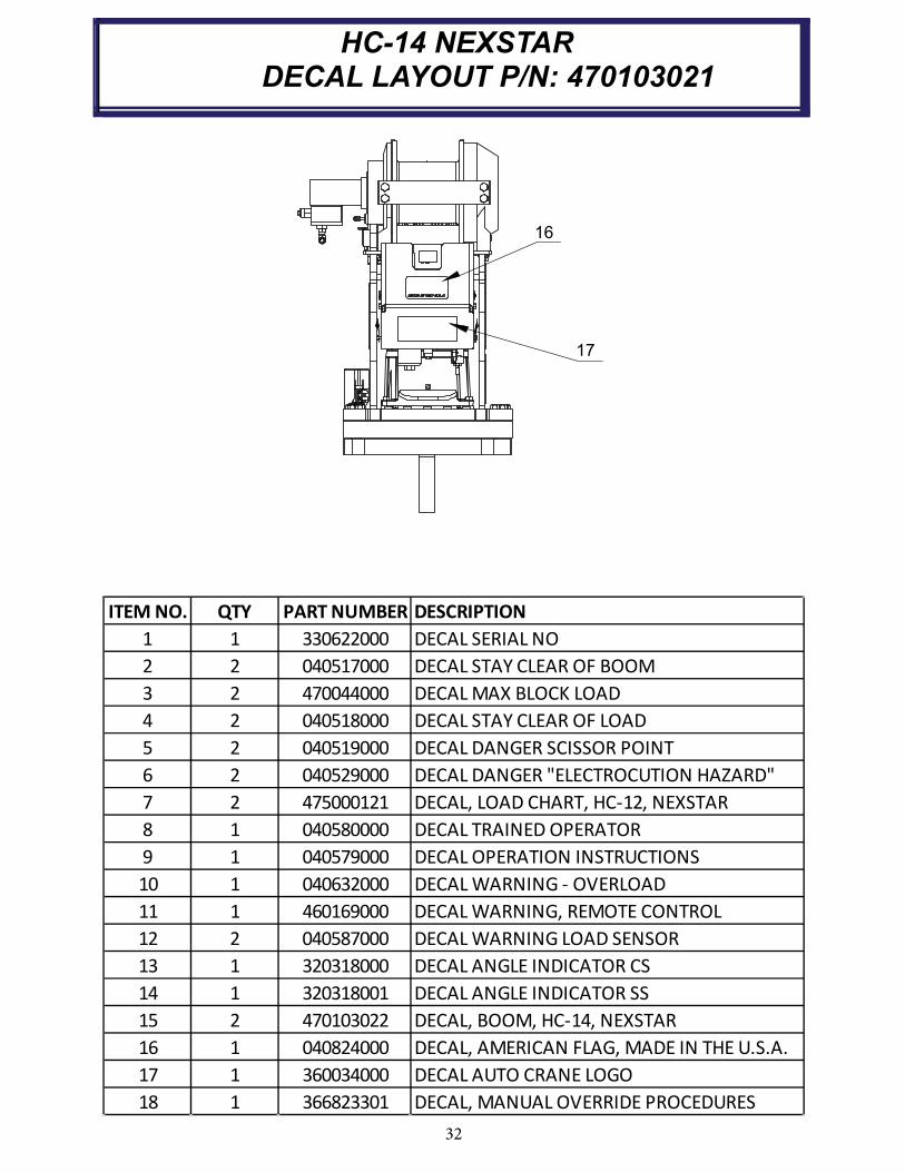
HC-14 NEXSTAR DECAL LAYOUT P/N: 470103021
16
17
ITEM NO. QTY PART NUMBER DESCRIPTION
1 1 330622000 DECAL SERIAL NO
2 2 040517000 DECAL STAY CLEAR OF BOOM
3 2 470044000 DECAL MAX BLOCK LOAD
4 2 040518000 DECAL STAY CLEAR OF LOAD
5 2 040519000 DECAL DANGER SCISSOR POINT
6 2 040529000 DECAL DANGER "ELECTROCUTION HAZARD"
7 2 475000121 DECAL, LOAD CHART, HC-12, NEXSTAR
8 1 040580000 DECAL TRAINED OPERATOR
9 1 040579000 DECAL OPERATION INSTRUCTIONS
10 1 040632000 DECAL WARNING - OVERLOAD
11 1 460169000 DECAL WARNING, REMOTE CONTROL
12 2 040587000 DECAL WARNING LOAD SENSOR
13 1 320318000 DECAL ANGLE INDICATOR CS
14 1 320318001 DECAL ANGLE INDICATOR SS
15 2 470103022 DECAL, BOOM, HC-14, NEXSTAR
16 1 040824000 DECAL, AMERICAN FLAG, MADE IN THE U.S.A.
17 1 360034000 DECAL AUTO CRANE LOGO
18 1 366823301 DECAL, MANUAL OVERRIDE PROCEDURES
33
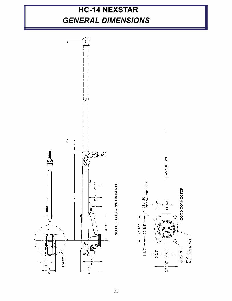
HC-14 NEXSTAR
GENERAL DIMENSIONS
NO
TE
: C
G I
S A
PP
RO
XIM
AT
E

34
NOTES

35
HC-14 NEXSTAR
MOUNTING AND INSTALLATION
ITEM NO. QTY PART NUMBER DESCRIPTION
1 8 015104000 SCREW HX HD 7/8 UNF X 5 GR 8
2 8 022200000 WASHER SP LK 7/8 CP
3 8 018900000 NUT HX 7/8 NFCP GR8
4 1 480689000 FUSE 15 AMP TIME-DELAY
5 1 480688000 FUSE HOLDER IN-LINE WATERPROOF
6 120 800596000 WIRE 16G 600V 1C YEL
7 6 634401000 TIE CABLE-MEDIUM
8 6 750738000 STICK-ON, CABLE TIE MOUNT
9 5 320357000 TERMINAL NON-INS S/O W/L
10 1 340638000 CONDUCTOR POWER
11 1 320355000 RELAY DROP OUT
12 1 320363000 PLUG TERMINAL CONNECTOR
13 1 470103110 MANUAL, HC-14, NEXSTAR II
14 1 470103026 DECAL, LOAD CHART, HC-14
1. Check to make sure the following items are with your crane. Please note the different, model specific, quantities.
B. PRESSURE LINE from pump to crane -10SAE 100R12 min (or equivalent) with a 2,850 PSI MINIMUM
WORKING PRESSURE. Hose lengths are determined by installer. Hose end fittings are both -10JIC
fe male swivel.
IMPORTANT: The recommended hydraulic reservoir size for the average industry application CRANE ONLY installation is two times the crane hydraulic flow rate. For crane applications requiring more than 25% crane operation time while the PTO is engaged and/or additional equip- ment is operated by the same hydraulic system, it is recommended that an appropriate sized larger
hydraulic reservoir and/or forced air, hydraulic oil cooler be installed.
CAUTION - AILURE TO USE CLEAN HYDRAULIC HOSES AND COMPONENTS
MAY CONTAMINATE THE CRANE AND HYDRAULIC SYSTEM AND VOID WARRANTY.
3. Crane must be provided with a flow of 15 to 19 gallons per minute and a pressure of 2800 PSI. Excess
flow will cause erratic operation, and too little flow will cause poor crane operation.
CAUTION - HYDRAULIC RESERVOIR OIL TEMPERATURE MUST NOT EXCEED 180°F OR CRANE
PERFORMANCE MAY BE ADVERSELY AFFECTED.
5. he vehicle MUST be equipped with an engine speed control and tachometer.
6. Make sure mounting surface is properly reinforced to withstand 70,000 ft-lb capacity loading of crane
and that outriggers are used to provide total stability for the truck.
4. Vehicle should meet minimum GVW rating of 129,000 pounds.
2. Pressure and return hoses are not furnished with this crane. The hoses must be provided by the
installer and the lengths determined at installation.
REQUIREMENTS FOR INSTALLATION
A. RETURN LINE from crane to reservoir (in compartment) -12 SAE 100R2 (or equivalent). Hose length is
determined by installer. Return lines longer than 6 feet should be size -12. Hose end fittings are -12JIC female swivel (crane end) and -12 JIC female swivel (reservoir end).
36
HC-14 NEXSTAR
MOUNTING AND INSTALLATION
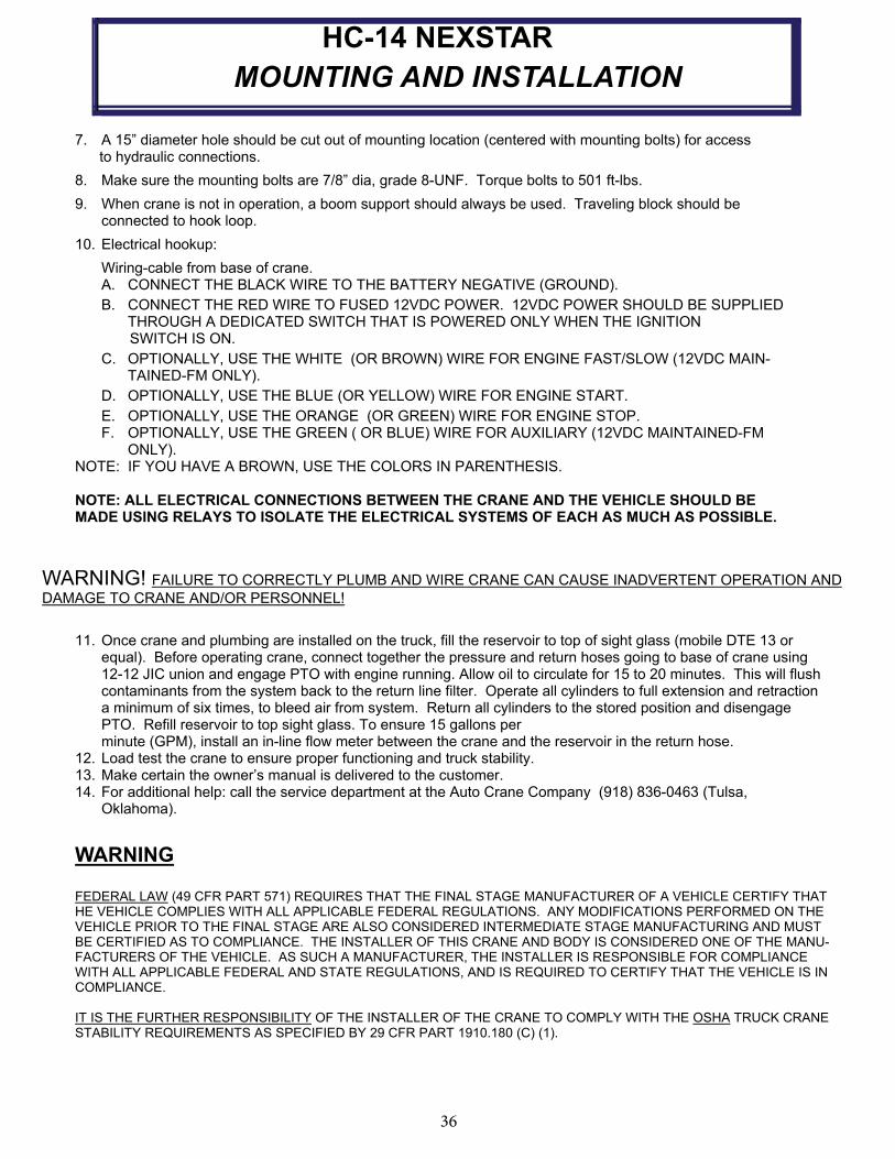
7. A 15” diameter hole should be cut out of mounting location (centered with mounting bolts) for access to hydraulic connections.
8. Make sure the mounting bolts are 7/8” dia, grade 8-UNF. Torque bolts to 501 ft-lbs.
9. When crane is not in operation, a boom support should always be used. Traveling block should be connected to hook loop.
10. Electrical hookup:
Wiring-cable from base of crane.A. CONNECT THE BLACK WIRE TO THE BATTERY NEGATIVE (GROUND).
B. CONNECT THE RED WIRE TO FUSED 12VDC POWER. 12VDC POWER SHOULD BE SUPPLIED THROUGH A DEDICATED SWITCH THAT IS POWERED ONLY WHEN THE IGNITION
SWITCH IS ON.
C. OPTIONALLY, USE THE WHITE (OR BROWN) WIRE FOR ENGINE FAST/SLOW (12VDC MAIN-TAINED-FM ONLY).
D. OPTIONALLY, USE THE BLUE (OR YELLOW) WIRE FOR ENGINE START.
E. OPTIONALLY, USE THE ORANGE (OR GREEN) WIRE FOR ENGINE STOP. F. OPTIONALLY, USE THE GREEN ( OR BLUE) WIRE FOR AUXILIARY (12VDC MAINTAINED-FM
ONLY). NOTE: IF YOU HAVE A BROWN, USE THE COLORS IN PARENTHESIS.
NOTE: ALL ELECTRICAL CONNECTIONS BETWEEN THE CRANE AND THE VEHICLE SHOULD BE MADE USING RELAYS TO ISOLATE THE ELECTRICAL SYSTEMS OF EACH AS MUCH AS POSSIBLE.
WARNING! FAILURE TO CORRECTLY PLUMB AND WIRE CRANE CAN CAUSE INADVERTENT OPERATION AND
DAMAGE TO CRANE AND/OR PERSONNEL!
11. Once crane and plumbing are installed on the truck, fill the reservoir to top of sight glass (mobile DTE 13 or equal). Before operating crane, connect together the pressure and return hoses going to base of crane using 12-12 JIC union and engage PTO with engine running. Allow oil to circulate for 15 to 20 minutes. This will flush contaminants from the system back to the return line filter. Operate all cylinders to full extension and retraction a minimum of six times, to bleed air from system. Return all cylinders to the stored position and disengage PTO. Refill reservoir to top sight glass. To ensure 15 gallons per
minute (GPM), install an in-line flow meter between the crane and the reservoir in the return hose. 12. Load test the crane to ensure proper functioning and truck stability. 13. Make certain the owner’s manual is delivered to the customer. 14. For additional help: call the service department at the Auto Crane Company (918) 836-0463 (Tulsa, Oklahoma).
FEDERAL LAW (49 CFR PART 571) REQUIRES THAT THE FINAL STAGE MANUFACTURER OF A VEHICLE CERTIFY THAT HE VEHICLE COMPLIES WITH ALL APPLICABLE FEDERAL REGULATIONS. ANY MODIFICATIONS PERFORMED ON THE VEHICLE PRIOR TO THE FINAL STAGE ARE ALSO CONSIDERED INTERMEDIATE STAGE MANUFACTURING AND MUST BE CERTIFIED AS TO COMPLIANCE. THE INSTALLER OF THIS CRANE AND BODY IS CONSIDERED ONE OF THE MANU-FACTURERS OF THE VEHICLE. AS SUCH A MANUFACTURER, THE INSTALLER IS RESPONSIBLE FOR COMPLIANCE WITH ALL APPLICABLE FEDERAL AND STATE REGULATIONS, AND IS REQUIRED TO CERTIFY THAT THE VEHICLE IS IN COMPLIANCE.
IT IS THE FURTHER RESPONSIBILITY OF THE INSTALLER OF THE CRANE TO COMPLY WITH THE OSHA TRUCK CRANE STABILITY REQUIREMENTS AS SPECIFIED BY 29 CFR PART 1910.180 (C) (1).
WARNING

37
HC-14 NEXSTAR GENERAL ASSEMBLY P/N 470103000
B
C
2
13
144
11
AA
21 13 12
161
17
D
E
SECTION A-A
DETAIL D
21 19
SLAVE
UNIT
20 21
18
CAN
CONNECTION
MASTER
UNIT
DETAIL B
5
6
8 9 10
DETAIL C
8 9 10
7
1
NOTE: APPLY LOCTITE 242 TO THREADS BEFORE INSTALLATION

38
HC-14 NEXSTAR
GENERAL ASSEMBLY
ITEM NO. QTY PART NO. DESCRIPTION
1 1 470103200 PEDESTAL ASSY, HC-14, NEXSTAR
2 1 470050000 BOOM ASSEMBLY, 14005H
3 1 002902000 SCREW SOC HD 1/4UNC X 1/2 GR8
4 1 366823236 LIGHT, LED (RED, GREEN, YELLOW)
5 1 470077000 PIN, CYLINDER 1.5 OD
6 1 239300000 ZERK, GREASE
7 1 470032000 PIN WLDMNT, BOOM PIVOT, 14005
8 2 320976000 WASHER, FLAT, 3/8 SAE HARDENED
9 2 021100000 WASHER SP LK 3/8
10 2 366159000 SCREW HX HD 3/8-16UNC X 1 1/2 LG GR8
11 1 470076000 PIN, 1 DIA 4-11/16 LG
12 1 360124000 PIN HITCH
13 1 470017000 WIRE ROPE ASS'Y 1/2
14 1 470025000 TRAVELING BLOCK ASSEMBLY
15 2 360677000 PIN, 1/4 COTTERLESS RING
16 1 750419000 CAP, 12 JIC
17 1 367238000 CAP, 10 JIC
18* 1 366823254 SENSOR, TRI-AXIS
19 2 015500000 NUT HX #8-32UNC CP
20 2 019700000 WASHER SP LK #8
21 4 1302000000 SCREW RD HD #8-32UNC X 1/2 LG
22 1 470103023 SHIP KIT, HC-14, NEXSTAR
23 1 470103021 DECAL LAYOUT, HC-14, NEXSTAR
24 1 330622000 DECAL SERIAL NO
* FOR REFERENCE ONLY
39
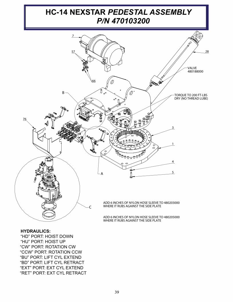
HC-14 NEXSTAR PEDESTAL ASSEMBLYP/N 470103200
A
B
C
3
1
4
5
66
57
7
VALVE
480188000
76
ADD 6 INCHES OF NYLON HOSE SLEEVE TO 480203000
WHERE IT RUBS AGAINST THE SIDE PLATE
ADD 6 INCHES OF NYLON HOSE SLEEVE TO 480205000
WHERE IT RUBS AGAINST THE SIDE PLATE
TORQUE TO 200 FT-LBS
DRY (NO THREAD LUBE)
28
HYDRAULICS:
“HD” PORT: HOIST DOWN
“HU” PORT: HOIST UP
“CW” PORT: ROTATION CW
“CCW” PORT: ROTATION CCW
“BU” PORT: LIFT CYL EXTEND
“BD” PORT: LIFT CYL RETRACT
“EXT” PORT: EXT CYL EXTEND
“RET” PORT: EXT CYL RETRACT

40
HC-14 NEXSTAR PEDESTAL ASSEMBLY NP/N 470103200
D54
53
37
40
39
38
34
29
58 56
59
303132
33
PLUG ADAPTER HARNESS P/N: 739316143 BETWEEN MAIN
HARNESS P/N: 366823257 AND PROXIMITY SWITCHES
P/N: 739316142
12
14
21
15
17
ADD 6 INCHES OF NYLON HOSE SLEEVE TO 480205000 WHERE IT RUBS AGAINST THE SIDE PLATE
ADD 6 INCHES OF NYLON HOSE SLEEVE TO 480203000 WHERE IT RUBS AGAINST THE SIDE PLATE
DETAIL C
36
44
4
41
35
71
72
45
46
47
4
43
42
32
VALVE BANK
HOSING DETAIL
67
67
RET
EXT
68
68
BD
BU
69
69
CCW
CW
70
70
HD
HU
DETAIL D
ROTATION SWITCH
DETAIL
12
14
21
15
17
26
25
20
19
18
16
26
24
2221
5
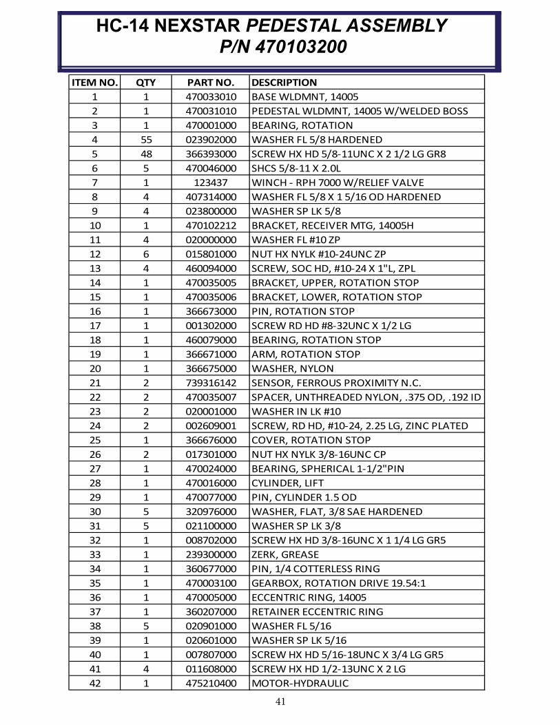
41
HC-14 NEXSTAR PEDESTAL ASSEMBLY P/N 470103200
ITEM NO. QTY PART NO. DESCRIPTION
1 1 470033010 BASE WLDMNT, 14005
2 1 470031010 PEDESTAL WLDMNT, 14005 W/WELDED BOSS
3 1 470001000 BEARING, ROTATION
4 55 023902000 WASHER FL 5/8 HARDENED
5 48 366393000 SCREW HX HD 5/8-11UNC X 2 1/2 LG GR8
6 5 470046000 SHCS 5/8-11 X 2.0L
7 1 123437 WINCH - RPH 7000 W/RELIEF VALVE
8 4 407314000 WASHER FL 5/8 X 1 5/16 OD HARDENED
9 4 023800000 WASHER SP LK 5/8
10 1 470102212 BRACKET, RECEIVER MTG, 14005H
11 4 020000000 WASHER FL #10 ZP
12 6 015801000 NUT HX NYLK #10-24UNC ZP
13 4 460094000 SCREW, SOC HD, #10-24 X 1"L, ZPL
14 1 470035005 BRACKET, UPPER, ROTATION STOP
15 1 470035006 BRACKET, LOWER, ROTATION STOP
16 1 366673000 PIN, ROTATION STOP
17 1 001302000 SCREW RD HD #8-32UNC X 1/2 LG
18 1 460079000 BEARING, ROTATION STOP
19 1 366671000 ARM, ROTATION STOP
20 1 366675000 WASHER, NYLON
21 2 739316142 SENSOR, FERROUS PROXIMITY N.C.
22 2 470035007 SPACER, UNTHREADED NYLON, .375 OD, .192 ID
23 2 020001000 WASHER IN LK #10
24 2 002609001 SCREW, RD HD, #10-24, 2.25 LG, ZINC PLATED
25 1 366676000 COVER, ROTATION STOP
26 2 017301000 NUT HX NYLK 3/8-16UNC CP
27 1 470024000 BEARING, SPHERICAL 1-1/2"PIN
28 1 470016000 CYLINDER, LIFT
29 1 470077000 PIN, CYLINDER 1.5 OD
30 5 320976000 WASHER, FLAT, 3/8 SAE HARDENED
31 5 021100000 WASHER SP LK 3/8
32 1 008702000 SCREW HX HD 3/8-16UNC X 1 1/4 LG GR5
33 1 239300000 ZERK, GREASE
34 1 360677000 PIN, 1/4 COTTERLESS RING
35 1 470003100 GEARBOX, ROTATION DRIVE 19.54:1
36 1 470005000 ECCENTRIC RING, 14005
37 1 360207000 RETAINER ECCENTRIC RING
38 5 020901000 WASHER FL 5/16
39 1 020601000 WASHER SP LK 5/16
40 1 007807000 SCREW HX HD 5/16-18UNC X 3/4 LG GR5
41 4 011608000 SCREW HX HD 1/2-13UNC X 2 LG
42 1 475210400 MOTOR-HYDRAULIC
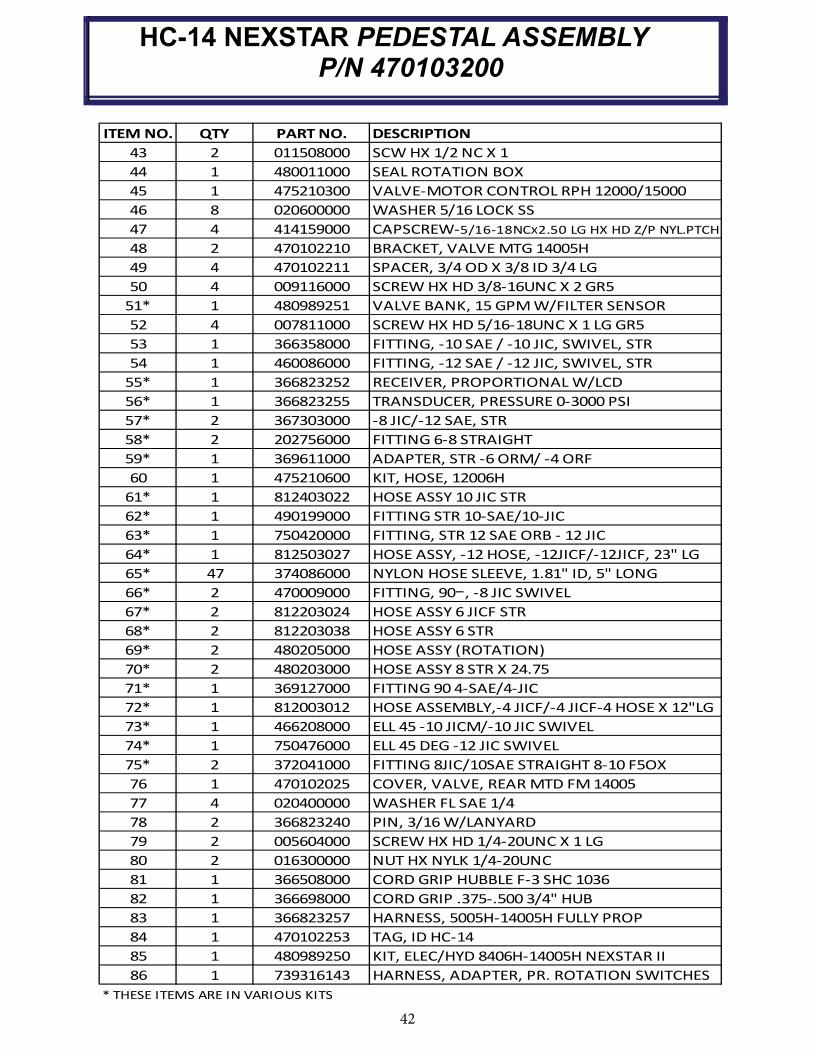
42
HC-14 NEXSTAR PEDESTAL ASSEMBLY P/N 470103200
ITEM NO. QTY PART NO. DESCRIPTION
43 2 011508000 SCW HX 1/2 NC X 1
44 1 480011000 SEAL ROTATION BOX
45 1 475210300 VALVE-MOTOR CONTROL RPH 12000/15000
46 8 020600000 WASHER 5/16 LOCK SS
47 4 414159000 CAPSCREW-5/16-18NCX2.50 LG HX HD Z/P NYL.PTCH
48 2 470102210 BRACKET, VALVE MTG 14005H
49 4 470102211 SPACER, 3/4 OD X 3/8 ID 3/4 LG
50 4 009116000 SCREW HX HD 3/8-16UNC X 2 GR5
51* 1 480989251 VALVE BANK, 15 GPM W/FILTER SENSOR
52 4 007811000 SCREW HX HD 5/16-18UNC X 1 LG GR5
53 1 366358000 FITTING, -10 SAE / -10 JIC, SWIVEL, STR
54 1 460086000 FITTING, -12 SAE / -12 JIC, SWIVEL, STR
55* 1 366823252 RECEIVER, PROPORTIONAL W/LCD
56* 1 366823255 TRANSDUCER, PRESSURE 0-3000 PSI
57* 2 367303000 -8 JIC/-12 SAE, STR
58* 2 202756000 FITTING 6-8 STRAIGHT
59* 1 369611000 ADAPTER, STR -6 ORM/ -4 ORF
60 1 475210600 KIT, HOSE, 12006H
61* 1 812403022 HOSE ASSY 10 JIC STR
62* 1 490199000 FITTING STR 10-SAE/10-JIC
63* 1 750420000 FITTING, STR 12 SAE ORB - 12 JIC
64* 1 812503027 HOSE ASSY, -12 HOSE, -12JICF/-12JICF, 23" LG
65* 47 374086000 NYLON HOSE SLEEVE, 1.81" ID, 5" LONG
66* 2 470009000 FITTING, 90 , -8 JIC SWIVEL
67* 2 812203024 HOSE ASSY 6 JICF STR
68* 2 812203038 HOSE ASSY 6 STR
69* 2 480205000 HOSE ASSY (ROTATION)
70* 2 480203000 HOSE ASSY 8 STR X 24.75
71* 1 369127000 FITTING 90 4-SAE/4-JIC
72* 1 812003012 HOSE ASSEMBLY,-4 JICF/-4 JICF-4 HOSE X 12"LG
73* 1 466208000 ELL 45 -10 JICM/-10 JIC SWIVEL
74* 1 750476000 ELL 45 DEG -12 JIC SWIVEL
75* 2 372041000 FITTING 8JIC/10SAE STRAIGHT 8-10 F5OX
76 1 470102025 COVER, VALVE, REAR MTD FM 14005
77 4 020400000 WASHER FL SAE 1/4
78 2 366823240 PIN, 3/16 W/LANYARD
79 2 005604000 SCREW HX HD 1/4-20UNC X 1 LG
80 2 016300000 NUT HX NYLK 1/4-20UNC
81 1 366508000 CORD GRIP HUBBLE F-3 SHC 1036
82 1 366698000 CORD GRIP .375-.500 3/4" HUB
83 1 366823257 HARNESS, 5005H-14005H FULLY PROP
84 1 470102253 TAG, ID HC-14
85 1 480989250 KIT, ELEC/HYD 8406H-14005H NEXSTAR II
86 1 739316143 HARNESS, ADAPTER, PR. ROTATION SWITCHES
* THESE ITEMS ARE IN VARIOUS KITS

43
NOTES
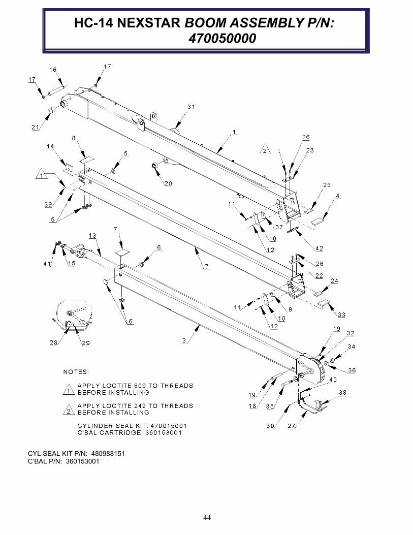
44
HC-14 NEXSTAR BOOM ASSEMBLY P/N: 470050000
CYL SEAL KIT P/N: 480988151 C’BAL P/N: 360153001
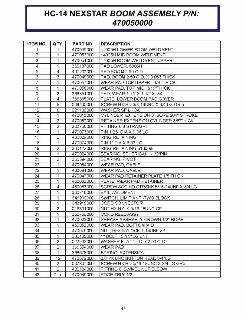
45
HC-14 NEXSTAR BOOM ASSEMBLY P/N: 470050000
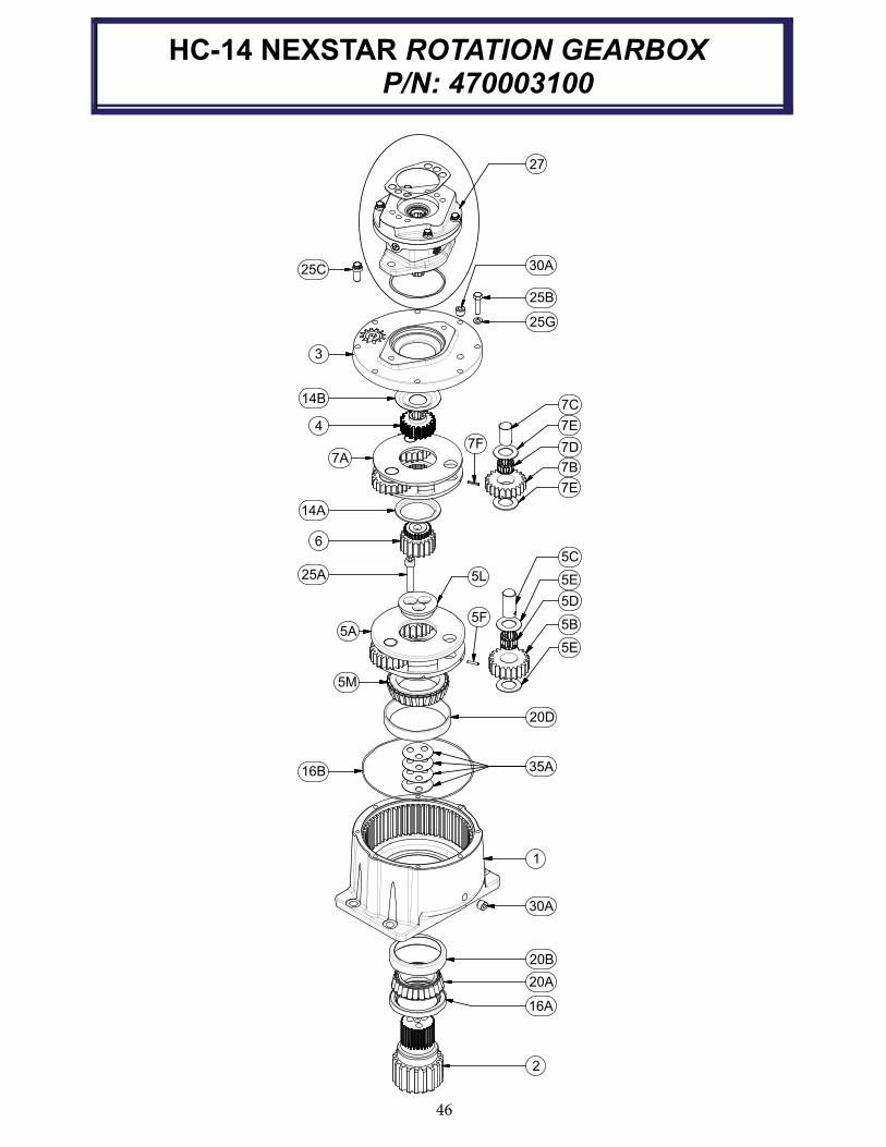
46
5C
5E
5D
5B
5E
5F
5A
5L
5M
25A
6
14A
7C
7E
7D
7B
7E
7F
7A
4
14B
3
30A25C
25B
25G
20D
35A16B
1
30A
20B
20A
16A
2
27
HC-14 NEXSTAR ROTATION GEARBOX P/N: 470003100

47
HC-14 NEXSTAR ROTATION GEARBOX P/N: 470003100
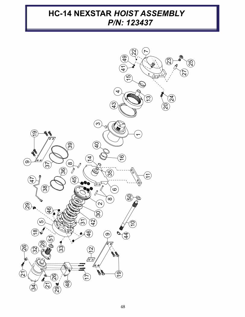
48
HC-14 NEXSTAR HOIST ASSEMBLY P/N: 123437
51
34 21
21
26
32
28
29
48
17
26
33
462
9
18
538
31
42
46
30
45
2
RP
H 7
000
(PA
RT
NO
. 123437)
44
19
10
9
50
86
9
37
19
39
36
8
14
35
12
11
23
25
24
274
149
22 7
TULSA OK
RAMSEY WINCH CO
43
4
13
20
3
1
16
40
15
47
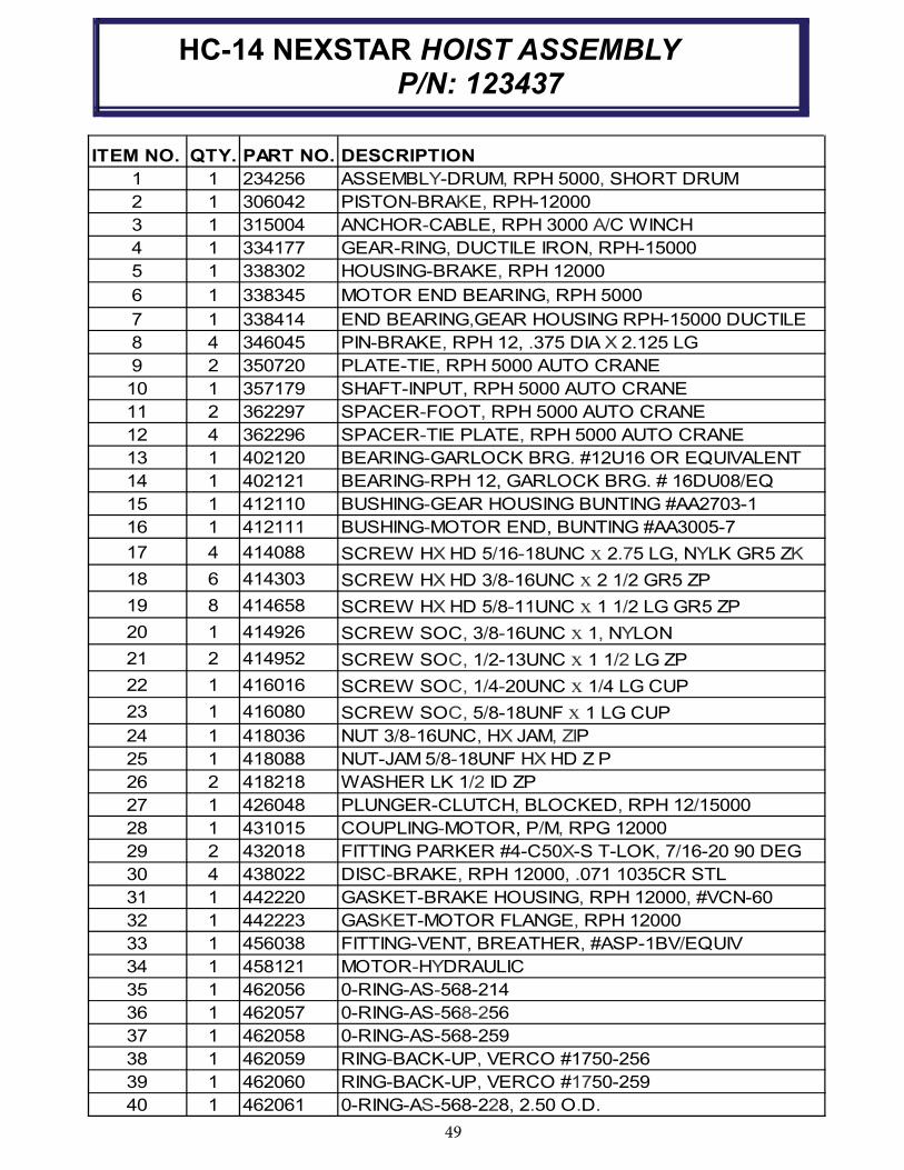
49
ITEM NO. QTY. PART NO. DESCRIPTION
1 1 234256 ASSEMBLY-DRUM, RPH 5000, SHORT DRUM
2 1 306042 PISTON-BRAKE, RPH-12000
3 1 315004 ANCHOR-CABLE, RPH 3000 A/C WINCH
4 1 334177 GEAR-RING, DUCTILE IRON, RPH-15000
5 1 338302 HOUSING-BRAKE, RPH 12000
6 1 338345 MOTOR END BEARING, RPH 5000
7 1 338414 END BEARING,GEAR HOUSING RPH-15000 DUCTILE
8 4 346045 PIN-BRAKE, RPH 12, .375 DIA X 2.125 LG
9 2 350720 PLATE-TIE, RPH 5000 AUTO CRANE
10 1 357179 SHAFT-INPUT, RPH 5000 AUTO CRANE
11 2 362297 SPACER-FOOT, RPH 5000 AUTO CRANE
12 4 362296 SPACER-TIE PLATE, RPH 5000 AUTO CRANE
13 1 402120 BEARING-GARLOCK BRG. #12U16 OR EQUIVALENT
14 1 402121 BEARING-RPH 12, GARLOCK BRG. # 16DU08/EQ
15 1 412110 BUSHING-GEAR HOUSING BUNTING #AA2703-1
16 1 412111 BUSHING-MOTOR END, BUNTING #AA3005-7
17 4 414088 SCREW HX HD 5/16-18UNC x 2.75 LG, NYLK GR5 ZK
18 6 414303 SCREW HX HD 3/8-16UNC x 2 1/2 GR5 ZP
19 8 414658 SCREW HX HD 5/8-11UNC x 1 1/2 LG GR5 ZP
20 1 414926 SCREW SOC, 3/8-16UNC x 1, NYLON
21 2 414952 SCREW SOC, 1/2-13UNC x 1 1/2 LG ZP
22 1 416016 SCREW SOC, 1/4-20UNC x 1/4 LG CUP
23 1 416080 SCREW SOC, 5/8-18UNF x 1 LG CUP
24 1 418036 NUT 3/8-16UNC, HX JAM, ZIP
25 1 418088 NUT-JAM 5/8-18UNF HX HD Z P
26 2 418218 WASHER LK 1/2 ID ZP
27 1 426048 PLUNGER-CLUTCH, BLOCKED, RPH 12/15000
28 1 431015 COUPLING-MOTOR, P/M, RPG 12000
29 2 432018 FITTING PARKER #4-C50X-S T-LOK, 7/16-20 90 DEG
30 4 438022 DISC-BRAKE, RPH 12000, .071 1035CR STL
31 1 442220 GASKET-BRAKE HOUSING, RPH 12000, #VCN-60
32 1 442223 GASKET-MOTOR FLANGE, RPH 12000
33 1 456038 FITTING-VENT, BREATHER, #ASP-1BV/EQUIV
34 1 458121 MOTOR-HYDRAULIC
35 1 462056 0-RING-AS-568-214
36 1 462057 0-RING-AS-568-256
37 1 462058 0-RING-AS-568-259
38 1 462059 RING-BACK-UP, VERCO #1750-256
39 1 462060 RING-BACK-UP, VERCO #1750-259
40 1 462061 0-RING-AS-568-228, 2.50 O.D.
HC-14 NEXSTAR HOIST ASSEMBLY P/N: 123437
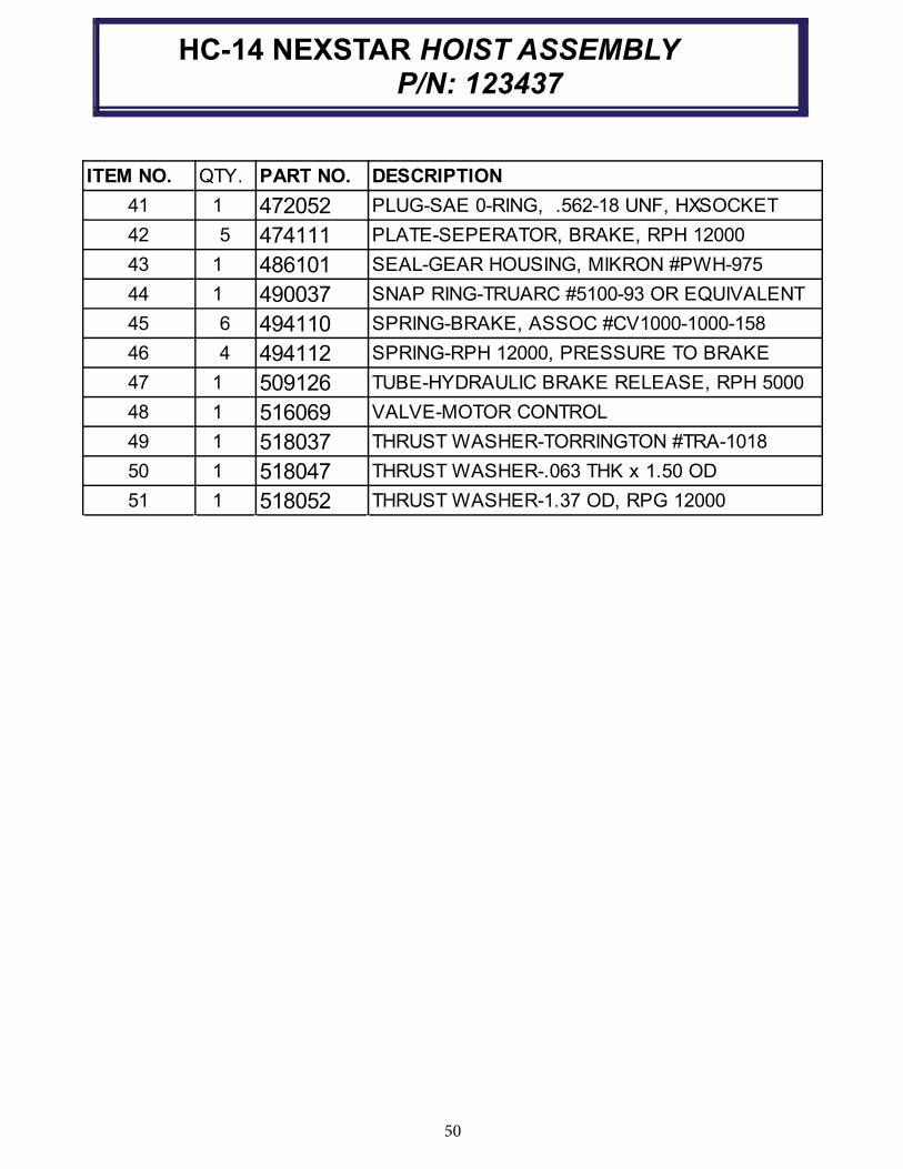
50
ITEM NO. QTY. PART NO. DESCRIPTION
41 1 472052 PLUG-SAE 0-RING, .562-18 UNF, HXSOCKET
42 5 474111 PLATE-SEPERATOR, BRAKE, RPH 12000
43 1 486101 SEAL-GEAR HOUSING, MIKRON #PWH-975
44 1 490037 SNAP RING-TRUARC #5100-93 OR EQUIVALENT
45 6 494110 SPRING-BRAKE, ASSOC #CV1000-1000-158
46 4 494112 SPRING-RPH 12000, PRESSURE TO BRAKE
47 1 509126 TUBE-HYDRAULIC BRAKE RELEASE, RPH 5000
48 1 516069 VALVE-MOTOR CONTROL
49 1 518037 THRUST WASHER-TORRINGTON #TRA-1018
50 1 518047 THRUST WASHER-.063 THK x 1.50 OD
51 1 518052 THRUST WASHER-1.37 OD, RPG 12000
HC-14 NEXSTAR HOIST ASSEMBLY P/N: 123437

51
HC-14 NEXSTAR TRAVELING BLOCK
P/N: 470025000

52
HC-10 NEXSTAR MAIN HARNESS
P/N: 366823257
CONNECTOR FUNCTION
J1 RECIEVER 18 PIN CONNECTION
J2 RECIEVER 30 PIN CONNECTION
J3 USB CONNECTION
J4 CAN CONNECTOR
J5 BOOM UP
J6 BOOM DOWN
J7 SWING CW
J8 SWING CCW
J9 BOOM RETRACT
J10 BOOM EXTEND
J11 HOIST A DOWN
J12 HOIST A UP
J13 HOIST B DOWN
J14 HOIST B UP
J15 ANTI-2 BLOCK
J16 DUMP VALVE
J17 BOOM ANGLE SENSOR
J18 PENDANT CONNECTION
J19 ALARM LIGHT
J20 ADDRESS
J21 BOOM PT
J22 DIRTY FILTER
J23 SWING LIMIT SWITCHES
J24 FAST IDLE MOMENTARY
CONNECTOR ID
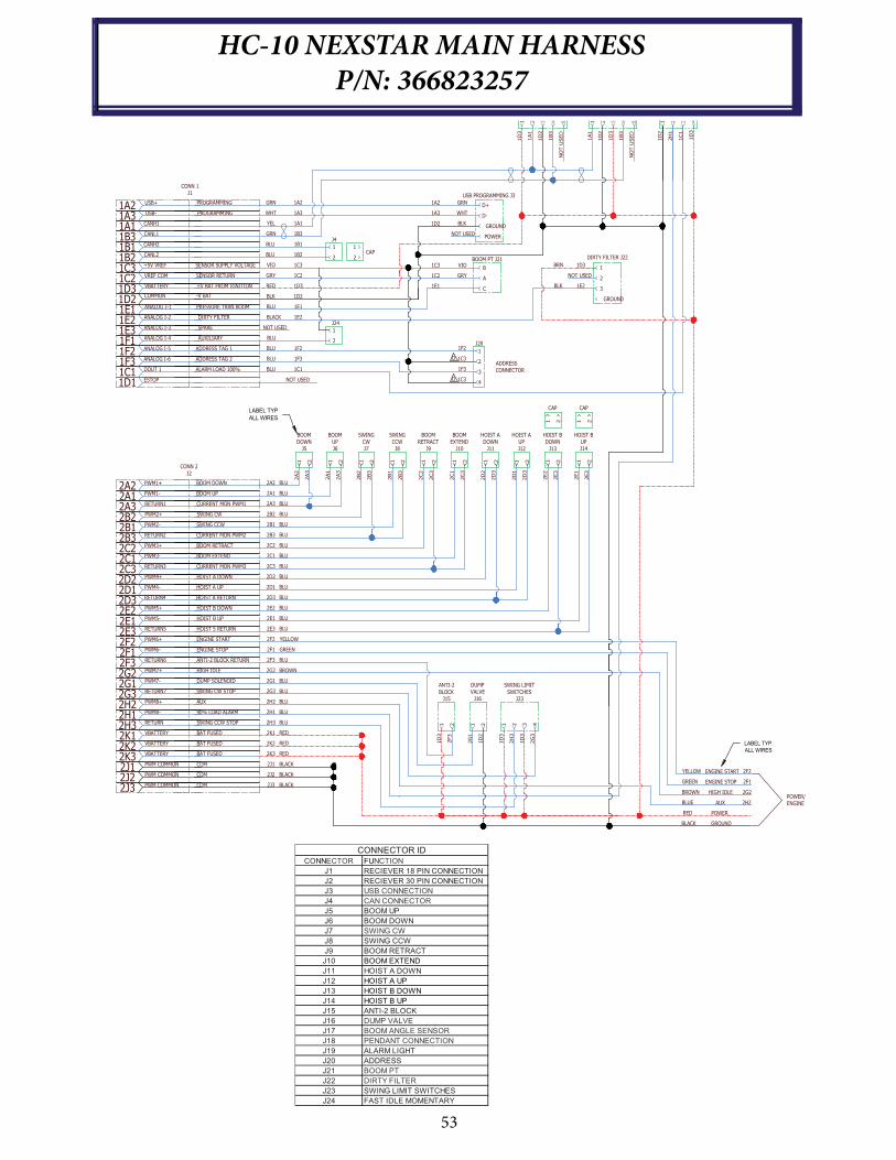
53
HC-10 NEXSTAR MAIN HARNESS
P/N: 366823257
1A2 USB+ GRN 1A2
1A3 USB- WHT 1A3
1A1 CANH1 YEL 1A1
1B3 CANL1 GRN 1B3
1B1 CANH2 1B1
1B2 CANL2 1B2
1C3 +5V VREF VIO 1C3
1C2 VREF COM GRY 1C2
1D3 VBATTERY RED 1D3
1D2COMMON BLK 1D2
1E1 ANALOG I-1 BLU 1E1
1E2 ANALOG I-2 BLACK 1E2
1E3 NOT USED
1F1 BLU
1F2 ANALOG I-5 BLU 1F2
1F3 ANALOG I-6 BLU 1F3
1C1 DOUT 1 BLU 1C1
1D1 NOT USED
HOIST B
UP
J14
1 2
2E1
2E3
HOIST B
DOWN
J13
1 2
2E2
2E3
HOIST A
UP
J12
1 2
2D
1
2D
3
HOIST A
DOWN
J11
1 2
2D
2
2D
3
BOOM
EXTEND
J101 2
2C1
2C3
BOOM
RETRACT
J9
1 2
2C2
2C3
SWING
CCW
J8
1 2
2B1
2B3
SWING
CW
J7
1 2
2B2
2B3
BOOM
UP
J6
1 2
2A1
2A3
BOOM
DOWN
J5
1 2
2A2
2A3
2A2 PWM1+ 2A2
2A1 PWM1- 2A1
2A3 RETURN1 2A3
2B2 PWM2+ 2B2
2B1 PWM2-
2B3 RETURN2
2C2 PWM3+ 2C2
2C1 PWM3- 2C1
2C3 RETURN3 2C3
2D2 PWM4+ 2D2
2D1 PWM4- 2D1
2D3 RETURN4 2D3
2E22E12E3 RETURN5 2E3
2F2 PWM6+ 2F2
2F1 PWM6- 2F1
2F3
ANTI-2
BLOCK
J15
1 2
1D
3
2F3
DUMP
VALVE
J16
1 2
2G
1
1D
2
SWING LIMIT
SWITCHES
J23
1 2
1D
3
2H
3
3 4
1D
3
2G
3
1D
3
1A1
1D
2
1B3
NO
T U
SED
1D
3
1A1
1D
2
1B3
NO
T U
SED
RETURN6 2F3
2G2 PWM7+ 2G2
2G1 PWM7- 2G1
2G3 RETURN7 2G3
2H2 PWM8+ 2H2
2H1 PWM8- 2H1
2H3 RETURN 2H3
2K1 VBATTERY 2K1
2K2 VBATTERY 2K2
2K3 VBATTERY 2K3
2J1 PWM COMMON 2J1
2J2 PWM COMMON 2J2
2J3 PWM COMMON 2J3
2B1
2B3
2E2
2E1PWM5-
PWM5+
D+
GROUND
POWER
D-
1
2
1
2
J4
B
A
C
NOT USED
BLK
WHT
GRN
1D2
1A3
1A2
1E1
1C2
1C3 1
2
3
GROUND
GRY
VIO
1C3
1F3
1C3
1F2
DIRTY FILTER J22BOOM PT J21
USB PROGRAMMING J3
J20
1
2
3
4
NOT USED
1D3
1E2
BRN
BLK
ENGINE START 2F2
ENGINE STOP 2F1
HIGH IDLE 2G2
AUX 2H2
POWER
GROUND
CAP
1D
2
2H
1
1C1
1D
3
POWER/
ENGINE
ADDRESS
CONNECTOR
YELLOW
GREEN
BROWN
BLUE
RED
BLACK
CAP
1 2
CAP
1 2
BOOM DOWN
BOOM UP
CURRENT MON PWM1
SWING CW
SWING CCW
CURRENT MON PWM2
BOOM RETRACT
BOOM EXTEND
CURRENT MON PWM3
HOIST A DOWN
HOIST A UP
HOIST A RETURN
HOIST 5 RETURN
ENGINE START
ENGINE STOP
ANTI-2 BLOCK RETURN
HIGH IDLE
DUMP SOLENOID
SWING CW STOP
AUX
90% LOAD ALARM
SWING CCW STOP
BAT FUSED
BAT FUSED
BAT FUSED
COM
COM
COM
HOIST B UP
HOIST B DOWN
CONN 2
J2
PROGRAMMING
PROGRAMMING
SENSOR SUPPLY VOLTAGE
SENSOR RETURN
+V BAT FROM IGNITION
-V BAT
PRESSURE TRAN BOOM
DIRTY FILTER
ADDRESS TAG 1
ADDRESS TAG 2
ALARM LOAD 100%
CONN 1
J1
SPARE
AUXILIARY
ANALOG I-3
ANALOG I-4
ESTOP
J24
2
1
BLU
BLU
BLU
BLU
BLU
BLU
BLU
BLU
BLU
BLU
BLU
BLU
BLU
BLU
BLU
BLU
BLU
YELLOW
GREEN
BLU
BROWN
BLU
BLU
BLU
BLU
BLU
RED
RED
RED
BLACK
BLACK
BLACK
LABEL TYP.
ALL WIRES
LABEL TYP
ALL WIRES
D
D
CONNECTOR FUNCTION
J1 RECIEVER 18 PIN CONNECTION
J2 RECIEVER 30 PIN CONNECTION
J3 USB CONNECTION
J4 CAN CONNECTOR
J5 BOOM UP
J6 BOOM DOWN
J7 SWING CW
J8 SWING CCW
J9 BOOM RETRACT
J10 BOOM EXTEND
J11 HOIST A DOWN
J12 HOIST A UP
J13 HOIST B DOWN
J14 HOIST B UP
J15 ANTI-2 BLOCK
J16 DUMP VALVE
J17 BOOM ANGLE SENSOR
J18 PENDANT CONNECTION
J19 ALARM LIGHT
J20 ADDRESS
J21 BOOM PT
J22 DIRTY FILTER
J23 SWING LIMIT SWITCHES
J24 FAST IDLE MOMENTARY
CONNECTOR ID

54
HC-14 NEXSTAR II
HYDRAULIC CONTROL VALVE
#8 JIC
TYP (2) PLCS
#6 JIC
TYP (6) PLCS
20
21
2222
26
27
20
21
1919
5/16-18 X .75 DEEP
TYP (2) PLCS
#6 SAE GAUGEPORT
29
10
11
10
10
12
3
16
13
12
5
14
4
6
1
17
2
27MM HEX
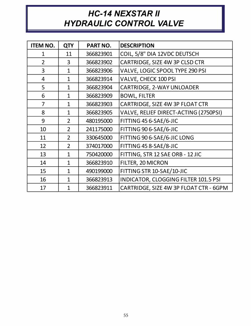
55
HC-14 NEXSTAR II
HYDRAULIC CONTROL VALVE
ITEM NO. QTY PART NO. DESCRIPTION
1 11 366823901 COIL, 5/8" DIA 12VDC DEUTSCH
2 3 366823902 CARTRIDGE, SIZE 4W 3P CLSD CTR
3 1 366823906 VALVE, LOGIC SPOOL TYPE 290 PSI
4 1 366823914 VALVE, CHECK 100 PSI
5 1 366823904 CARTRIDGE, 2-WAY UNLOADER
6 1 366823909 BOWL, FILTER
7 1 366823903 CARTRIDGE, SIZE 4W 3P FLOAT CTR
8 1 366823905 VALVE, RELIEF DIRECT-ACTING (2750PSI)
9 2 480195000 FITTING 45 6-SAE/6-JIC
10 2 241175000 FITTING 90 6-SAE/6-JIC
11 2 330645000 FITTING 90 6-SAE/6-JIC LONG
12 2 374017000 FITTING 45 8-SAE/8-JIC
13 1 750420000 FITTING, STR 12 SAE ORB - 12 JIC
14 1 366823910 FILTER, 20 MICRON
15 1 490199000 FITTING STR 10-SAE/10-JIC
16 1 366823913 INDICATOR, CLOGGING FILTER 101.5 PSI
17 1 366823911 CARTRIDGE, SIZE 4W 3P FLOAT CTR - 6GPM
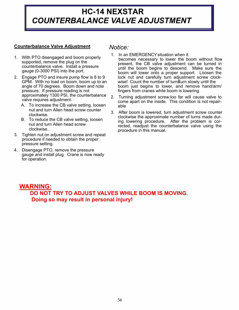
56
HC-14 NEXSTARCOUNTERBALANCE VALVE ADJUSTMENT
Counterbalance Valve Adjustment
1. With PTO disengaged and boom properly supported, remove the plug on the counterbalance valve. Install a pressure gauge (0-3000 PSI) into the port.
2. Engage PTO and insure pump flow is 8 to 9 GPM. With no load on boom, boom up to an angle of 70 degrees. Boom down and note pressure. If pressure reading is not approximately 1300 PSI, the counterbalance valve requires adjustment.
A. To increase the CB valve setting, loosen nut and turn Allen head screw counter clockwise. B. To reduce the CB valve setting, loosen nut and turn Allen head screw clockwise.
3. Tighten nut on adjustment screw and repeat procedure if needed to obtain the proper pressure setting.
4. Disengage PTO, remove the pressure gauge and install plug. Crane is now ready for operation.
Notice:
1. In an EMERGENCYsituation when it becomes necessary to lower the boom without flow
present, the CB valve adjustment can be turned in until the boom begins to descend. Make sure the boom will lower onto a proper support. Loosen the lock nut and carefully turn adjustment screw clock-wise! Count the number of turns. Turn slowly until the boom just begins to lower, and remove hand/arm/fingers from cranes while boom is lowering.
2. Turning adjustment screw too far will cause valve to come apart on the inside. This condition is not repair-able
3. After boom is lowered, turn adjustment screw counter clockwise the approximate number of turns made dur-ing lowering procedure. After the problem is cor-rected, readjust the counterbalance valve using the procedure in this manual.
WARNING:DO NOT TRY TO ADJUST VALVES WHILE BOOM IS MOVING.Doing so may result in personal injury!
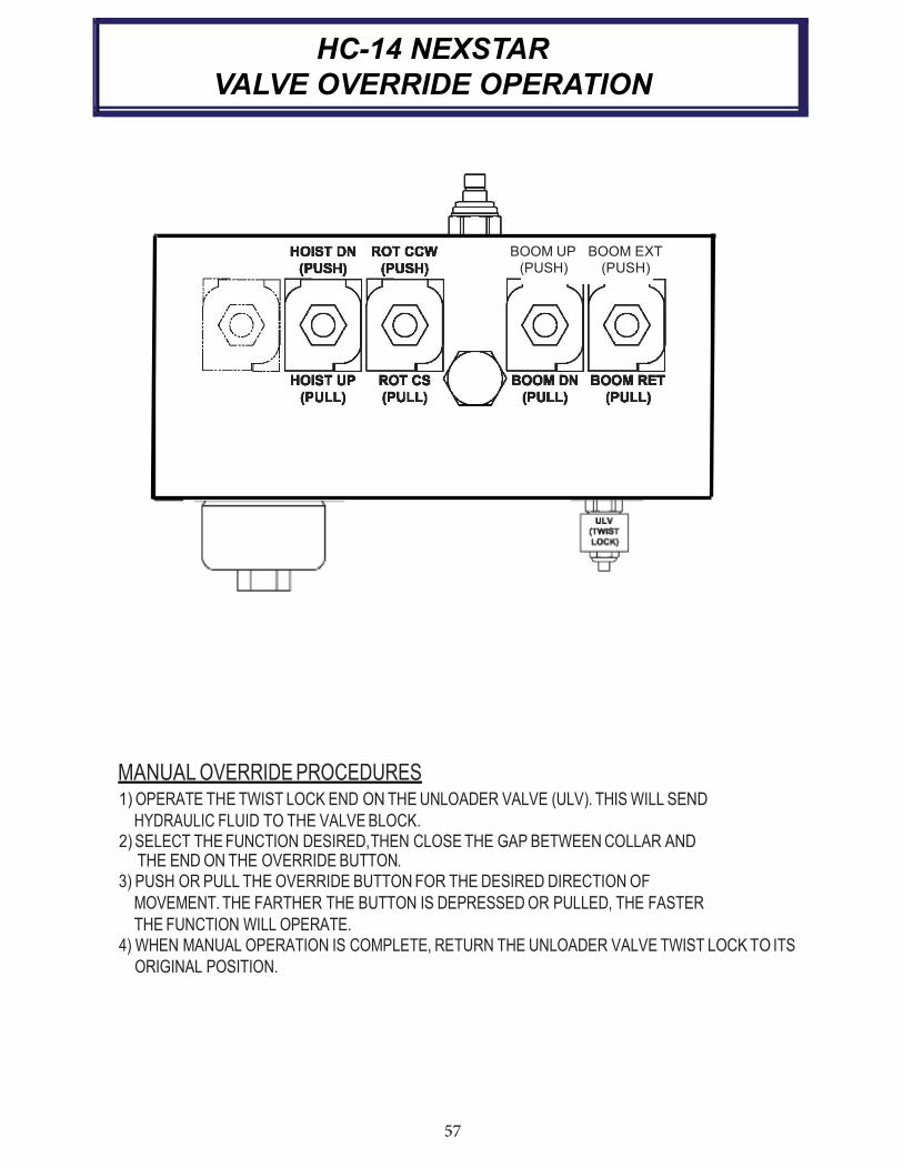
57
HC-14 NEXSTAR
VALVE OVERRIDE OPERATION
BOOM UP BOOM EXT
(PUSH) (PUSH)
ULV
(TWIST
LOCK)
MANUAL OVERRIDE PROCEDURES 1) OPERATE THE TWIST LOCK END ON THE UNLOADER VALVE (ULV). THIS WILL SEND
HYDRAULIC FLUID TO THE VALVE BLOCK. 2) SELECT THE FUNCTION DESIRED,THEN CLOSE THE GAP BETWEEN COLLAR AND
THE END ON THE OVERRIDE BUTTON. 3) PUSH OR PULL THE OVERRIDE BUTTON FOR THE DESIRED DIRECTION OF
MOVEMENT. THE FARTHER THE BUTTON IS DEPRESSED OR PULLED, THE FASTER
THE FUNCTION WILL OPERATE. 4) WHEN MANUAL OPERATION IS COMPLETE, RETURN THE UNLOADER VALVE TWIST LOCK TO ITS
ORIGINAL POSITION.
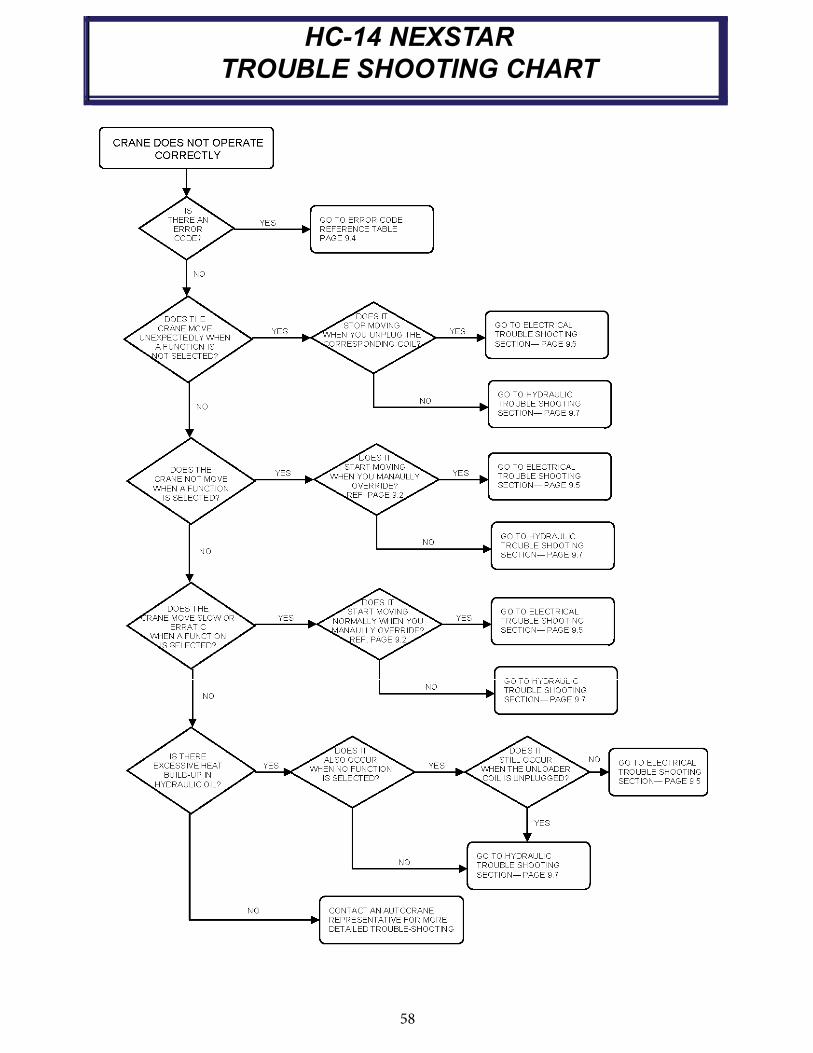
58
SECTION UNDER DEVELOPMENT
HC-14 NEXSTAR
TROUBLE SHOOTING CHART
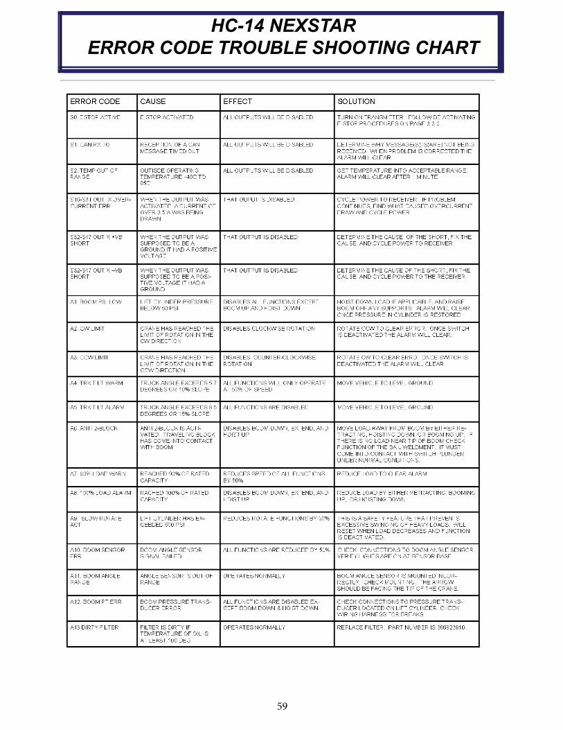
59
HC-14 NEXSTAR
ERROR CODE TROUBLE SHOOTING CHART
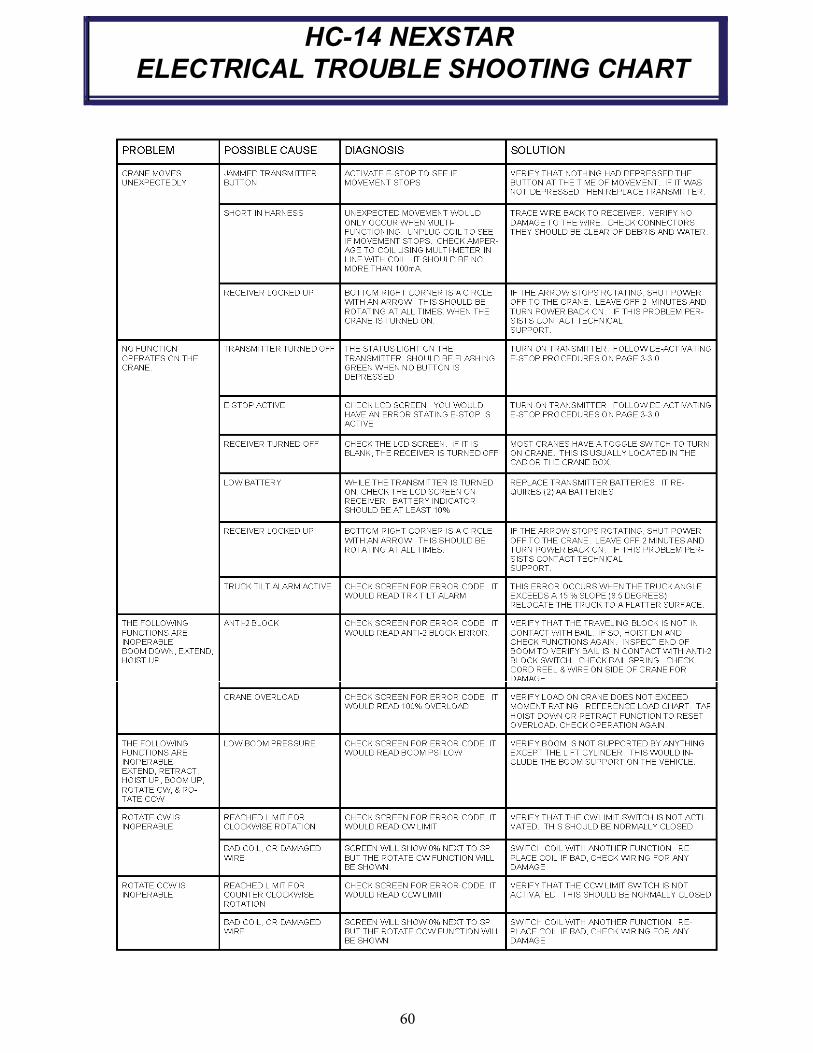
60
HC-14 NEXSTAR
ELECTRICAL TROUBLE SHOOTING CHART

61
HC-14 NEXSTAR
ELECTRICAL TROUBLE SHOOTING CHART
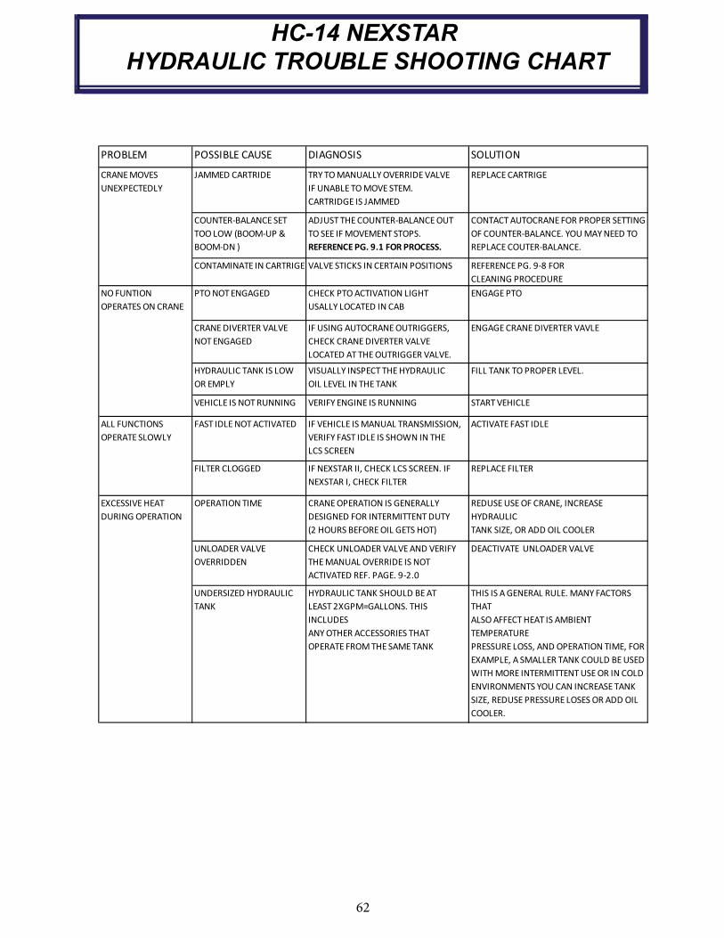
62
PROBLEM POSSIBLE CAUSE DIAGNOSIS SOLUTION
JAMMED CARTRIDE TRY TOMANUALLYOVERRIDEVALVE
IF UNABLE TOMOVESTEM.
CARTRIDGE IS JAMMED
REPLACECARTRIGE
COUNTER BALANCESET
TOO LOW (BOOM UP &
BOOM DN )
ADJUSTTHECOUNTER BALANCEOUT
TO SEE IFMOVEMENT STOPS.
REFERENCEPG. 9.1 FORPROCESS.
CONTACTAUTOCRANEFOR PROPER SETTING
OF COUNTER BALANCE. YOUMAYNEED TO
REPLACECOUTER BALANCE.
CONTAMINATE IN CARTRIGE VALVE STICKS IN CERTAIN POSITIONS REFERENCEPG. 9 8 FOR
CLEANING PROCEDURE
PTONOTENGAGED CHECK PTOACTIVATION LIGHT
USALLY LOCATED IN CAB
ENGAGEPTO
CRANEDIVERTER VALVE
NOTENGAGED
IF USING AUTOCRANEOUTRIGGERS,
CHECK CRANEDIVERTER VALVE
LOCATED ATTHEOUTRIGGER VALVE.
ENGAGECRANEDIVERTER VAVLE
HYDRAULIC TANK IS LOW
OR EMPLY
VISUALLY INSPECT THEHYDRAULIC
OIL LEVEL IN THETANK
FILL TANK TOPROPER LEVEL.
VEHICLE IS NOTRUNNING VERIFY ENGINE IS RUNNING STARTVEHICLE
FAST IDLENOTACTIVATED IF VEHICLE ISMANUAL TRANSMISSION,
VERIFY FAST IDLE IS SHOWN IN THE
LCS SCREEN
ACTIVATE FAST IDLE
FILTER CLOGGED IF NEXSTAR II, CHECK LCS SCREEN. IF
NEXSTAR I, CHECK FILTER
REPLACE FILTER
OPERATION TIME CRANEOPERATION IS GENERALLY
DESIGNED FOR INTERMITTENTDUTY
(2 HOURS BEFOREOIL GETS HOT)
REDUSEUSEOF CRANE, INCREASE
HYDRAULIC
TANK SIZE, OR ADD OIL COOLER
UNLOADER VALVE
OVERRIDDEN
CHECK UNLOADER VALVEAND VERIFY
THEMANUAL OVERRIDE IS NOT
ACTIVATED REF. PAGE. 9 2.0
DEACTIVATE UNLOADER VALVE
UNDERSIZED HYDRAULIC
TANK
HYDRAULIC TANK SHOULD BEAT
LEAST2XGPM=GALLONS. THIS
INCLUDES
ANYOTHER ACCESSORIES THAT
OPERATE FROMTHESAMETANK
THIS IS AGENERAL RULE. MANYFACTORS
THAT
ALSOAFFECTHEAT IS AMBIENT
TEMPERATURE
PRESSURE LOSS, AND OPERATION TIME, FOR
EXAMPLE, A SMALLER TANK COULD BEUSED
WITHMORE INTERMITTENTUSEOR IN COLD
ENVIRONMENTS YOU CAN INCREASETANK
SIZE, REDUSEPRESSURE LOSES OR ADD OIL
COOLER.
CRANEMOVES
UNEXPECTEDLY
NOFUNTION
OPERATES ONCRANE
ALL FUNCTIONS
OPERATESLOWLY
EXCESSIVEHEAT
DURING OPERATION
HC-14 NEXSTAR
HYDRAULIC TROUBLE SHOOTING CHART


64
HC-14 NEXSTAR
CARTRIDGE MAINTENANCE
Clean the area around the valve spool to be removed from the valve bank
Remove the valve spool from the valve bank being careful not to touch or hit surrounding objects
Carefully remove any visible debris from the valve spool
The recommended cleaning fluid is off-the-shelf automotive brake cleaning fluid.
It is recommended the skin and eye protection be worn when spraying the valve spool clean.
Inspect o-rings for damage and replace if needed
Dip the valve spool into fresh hydraulic oil to lubricate and fill cavities
Reinstall the valve spool in the reverse order in which it was removed
Validate function operation of the crane
VERIFY MOVEMENT IN PORTS WHILE
MANUALLY OVER-RIDING CARTRIDGE.
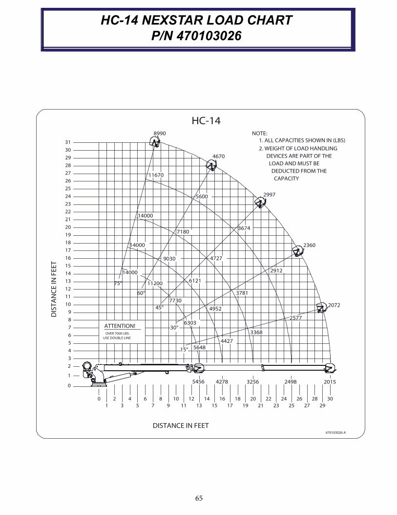
65
HC-14 NEXSTAR LOAD CHART
P/N 470103026
HC-14
DEDUCTED FROM THE
NOTE:
2. WEIGHT OF LOAD HANDLING
1. ALL CAPACITIES SHOWN IN (LBS)
LOAD AND MUST BE
DEVICES ARE PART OF THE
CAPACITY
2072
2015
29
30
4670
2997
8990
5600
11670
2912
3674
2577
3781
3368
7180
9030
14000
14000
6121
7730
30°6303
60°
75°
45°
11200
14000
4727
4952
31
29
30
27
28
25
23
24
26
21
19
20
17
15
16
18
13
11
12
9
7
8
10
14
DIS
TA
NC
E I
N F
EE
T
22
ATTENTION!
OVER 7000 LBS.
2498
4427
32564278
2723 2521191715
470103026 A
16 18 20 22 24 26
564815°
5456
139 11753
2 4 6 8 10 1412
DISTANCE IN FEET
5
3
4
1
2
0
0
1
USE DOUBLE LINE6
28
2360
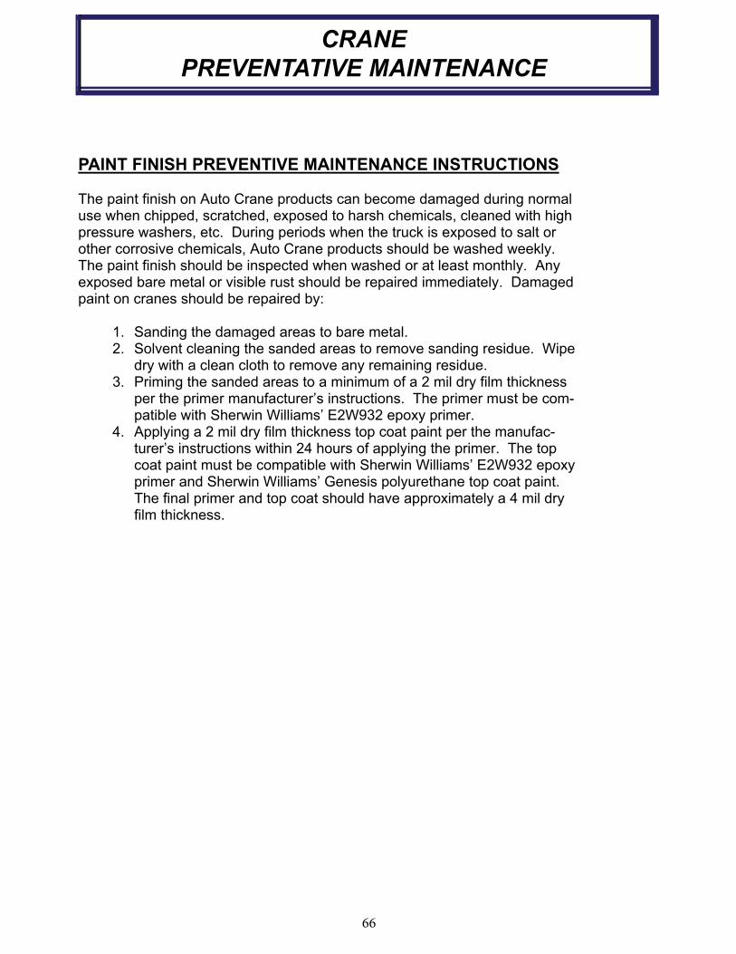
66
CRANE
PREVENTATIVE MAINTENANCE
PAINT FINISH PREVENTIVE MAINTENANCE INSTRUCTIONS
The paint finish on Auto Crane products can become damaged during normal use when chipped, scratched, exposed to harsh chemicals, cleaned with high pressure washers, etc. During periods when the truck is exposed to salt or other corrosive chemicals, Auto Crane products should be washed weekly.The paint finish should be inspected when washed or at least monthly. Any exposed bare metal or visible rust should be repaired immediately. Damaged paint on cranes should be repaired by:
1. Sanding the damaged areas to bare metal. 2. Solvent cleaning the sanded areas to remove sanding residue. Wipe
dry with a clean cloth to remove any remaining residue. 3. Priming the sanded areas to a minimum of a 2 mil dry film thickness
per the primer manufacturer’s instructions. The primer must be com-patible with Sherwin Williams’ E2W932 epoxy primer.
4. Applying a 2 mil dry film thickness top coat paint per the manufac-turer’s instructions within 24 hours of applying the primer. The top coat paint must be compatible with Sherwin Williams’ E2W932 epoxy primer and Sherwin Williams’ Genesis polyurethane top coat paint. The final primer and top coat should have approximately a 4 mil dry film thickness.

P.O.Box 580697 Tulsa, OK 74158-0697
4707 N. Mingo Rd. Phone (918) 438-2760
LIMITED WARRANTY1 YEAR PURCHASED REPLACEMENT PARTS
Auto Crane will warranty to the consumer for a period of (1) year from the date that a new Auto Crane replacement part was purchased from an authorized Auto Crane distributor. Each new Auto Crane part they sell will be free under normal use and service from defects in material andworkmanship. Date of purchase will be honored as the date indicated on the Bill of Sale to the consumer.
The obligation of Auto Crane under this warranty does not apply to parts replaced under thelimited warranty for a new Auto Crane product. The warranty for parts replaced under the limited warranty of a new Auto Crane product expires when the warranty for that product expires.
The obligation of Auto Crane under this warranty is limited to the replacement or repair ofpurchased replacement parts that appear to the manufacturer to be defective after review ofdocumentation (Auto Crane Warranty Claim Form. photos. data etc.) provided by the Auto Cranedistributor and/or inspection of parts returned to Auto Crane. This warranty does not obligate AutoCrane to bear labor costs to replace the defective parts or travel time charges in connection with thereplacement or repair of defective parts. Responsibility for customer's claims arising from
misapplication. abuse. misuse or alteration of equipment or parts lies with the distributor or user andno warranty obligation is assumed in these circumstances by Auto Crane.
Auto Crane will in no event be liable for any consequential damages or contingent liabilitiesarising out of the failure of any Auto Crane product or parts to operate properly
Auto Crane makes no warranty in respect to parts for component accessories. it being subjectto the warranties of their respective manufacturers.
If field service, at the request of the distributor, is rendered and fault is found not to be with AutoCrane's product, the distributor shall pay the time and expense of the field representative.
Claims for service labor or other expenses that have incurred by the buyer without approval
or authorization or Auto Crane will not be accepted
When applying for warranty claims may be handled by contacting your nearest authorized Auto Crane Distributor. All claims are to be filed in writing on an Auto Crane Warranty Claim Form.
Limited Parts Warranty 1 Year Effective June 15. 2010


Auto Crane Company issues a limited warranty
certifi cate with each unit sold. See warranty page.
Auto Crane will not assume responsibility or liability
for any modifi cations or changes made to unit, or
installation of component parts without authorization.
Note: This manual should remain with the crane at all times.
