hb white motors series - cross hydraulics · white motors cross hydraulics pty ltd green catalogue...
TRANSCRIPT

WHITE MOTORS
CROSS HYDRAULICS PTY LTD GREEN CATALOGUE Page 8.35
HB SERIES
The HB Series motor is the leader in its class, offering high efficiency with rugged durability. The three-zone orbiting disk valve, laminated manifold and Roller Stator® motor work harmoniously to produce high overall efficiencies over a wide range of operating conditions. The standard case drain increases shaft seal life by reducing internal pressures experienced by the seal. The case leakage is also directed across all driveline components, increasing motor life. An internal drain option is also available. At the heart of the motor is a heavy-duty drivelink, offering 30% more torque capacity than competitive designs. These features make the HB Series motor the motor of choice for applications requiring peak efficiency for continuous operation.
FeaturesHeavy-Duty Drive Link is up to 30% stronger than competitive designs for longer life.
Three-Zone Orbiting Valve precisely meters oil to produce exceptional volumetric efficiency.
Standard Case Drain increases shaft seal life by reducing pressure on seal.
Rubber Energized Steel Face Seal does not extrude or melt under high pressure or high temperature.
Forced Drive Link Lubrication reduces wear and promotes longer life from motor.
Code0304
0506
0810
121418
24
Displacementin 3/rev
(cm3/rev)
3.2 (52)4.6 (76)
5.4 (89)6.8 (111)
7.7 (127)10.0 (164)
12.5 (205)15.5 (254)17.9 (293)
24.9 (409)
Max SpeedRPM
� Cont.� Inter.� 680� 830� 670� 950
� 680� 840� 680� 850
� 580� 740� 460� 580
� 370� 460� 290� 370� 250� 320
� 180� 230
Max FlowGPM (LPM)
� Cont.� Inter.� 10 (38)� 12 (45)� 14 (53)� 20 (76)
� 16 (61)� 20 (76)� 20 (76)� 25 (95)
� 20 (76)� 25 (95)� 20 (76)� 25 (95)� 20 (76)� 25 (95)� 20 (76)� 25 (95)
� 20 (76)� 25 (95)� 20 (76)� 25 (95)
Max Torquelb-in (Nm)
� Cont.� Inter.� *Stall� 1200 (135)� 1400 (158)� 885 (100)� 1700 (191)� 1975 (222)� 1370 (155)
� 2000 (225)� 2400 (270)� 1670 (189)� 2650 (298)� 3100 (349)� 2315 (261)
� 3000 (338)� 3500 (394)� 2560 (289)� 3975 (448)� 4550 (512)� 3530 (397)
� 5050 (569)� 5800 (653)� 4520 (509)� 6250 (704)� 7100 (799)� 5985 (674)� 7200 (811)� 8250 (929)� 6915 (779)
� 8400 (946)� 9050 (1019)� 7850 (887)
Pressure ∆PSI(∆---Bar)� Cont.� Inter.� Peak� 3000 (207)� 3500 (241)� 4000 (276)� 3000 (207)� 3500 (241)� 4000 (276)
� 3000 (207)� 3500 (241)� 4000 (276)� 3000 (207)� 3500 (241)� 4000 (276)
� 3000 (207)� 3500 (241)� 4000 (276)� 3000 (207)� 3500 (241)� 4000 (276)
� 3000 (207)� 3500 (241)� 4000 (276)� 3000 (207)� 3500 (241)� 4000 (276)� 3000 (207)� 3500 (241)� 4000 (276)
� 2500 (172)� 2750 (189)� 3000 (207)
WHITE MOTORS
CROSS HYDRAULICS PTY LTD GREEN CATALOGUE Page 8.36
HBSERIES
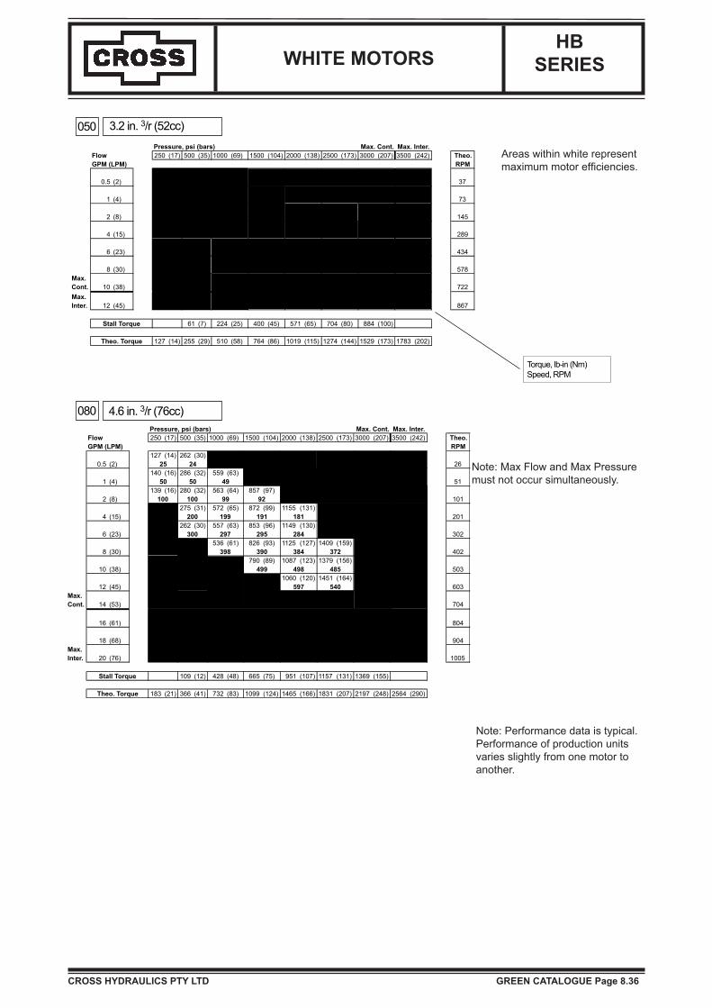
Note: Max Flow and Max Pressure must not occur simultaneously.
Note: Performance data is typical.Performance of production units varies slightly from one motor to another.
Areas within white represent maximum motor efficiencies.
050
080
3.2 in. 3/r (52cc)
4.6 in. 3/r (76cc)
Torque, lb-in (Nm)Speed, RPM

090
110
5.4 in. 3/r (89cc)
6.8 in. 3/r (111cc) Torque, lb-in (Nm)Speed, RPm
WHITE MOTORS
CROSS HYDRAULICS PTY LTD GREEN CATALOGUE Page 8.37
HBSERIES
Note: Max Flow and Max Pressure must not occur simultaneously.
Note: Performance data is typical.Performance of production units varies slightly from one motor to another.
Areas within white represent maximum motor efficiencies.

WHITE MOTORS
CROSS HYDRAULICS PTY LTD GREEN CATALOGUE Page 8.38
HBSERIES
Note: Max Flow and Max Pressure must not occur simultaneously.
Note: Performance data is typical.Performance of production units varies slightly from one motor to another.
Areas within white represent maximum motor efficiencies.
125
160
7.7 in. 3/r (127cc)
10.0 in. 3/r (164cc) Torque, lb-in (Nm)Speed, RPM

WHITE MOTORS
CROSS HYDRAULICS PTY LTD GREEN CATALOGUE Page 8.39
HBSERIES
Note: Max Flow and Max Pressure must not occur simultaneously.
Note: Performance data is typical.Performance of production units varies slightly from one motor to another.
Areas within white represent maximum motor efficiencies.
200
250
12.5 in. 3/r (205cc)
15.5 in. 3/r (254cc) Torque, lb-in (Nm)Speed, RPM

WHITE MOTORS
CROSS HYDRAULICS PTY LTD GREEN CATALOGUE Page 8.40
HBSERIES
Note: Max Flow and Max Pressure must not occur simultaneously.
Note: Performance data is typical.Performance of production units varies slightly from one motor to another.
Areas within white represent maximum motor efficiencies.
300
400
17.9 in. 3/r (293cc)
24.9 in. 3/r (409cc) Torque, lb-in (Nm)Speed, RPM

WHITE MOTORS
CROSS HYDRAULICS PTY LTD GREEN CATALOGUE Page 8.41
HBSERIES
A0 A7
A2 A8
A4 A9
2-Hole with Rear Ports 2-Hole with Side Ports
1.91 (49) Max
2.08 (53) Max
5.19 (132) Max
.522 (13.3)
.514 913.1)
O 4.187 (106.3)
Dim. D
.57 (14).210 (5.3).205 (5.2)
3.250 (82.6)3.242 (82.3)
.12 (3).06 (2)
Seal Groove Detail
4-Hole with Rear Ports 4-Hole with Rear Ports
1.91 (49) Max
2.08 (53) Max.522 (13.3).514 (13.1)
5.19 (132) Max
22.5o
45oO 4.187 (106.3)
Dim D
.57 (14).210 (5.3).205 (5.2)
3.250 (82.6)3.242 (82.3)
.12 (3).06 (2)
Seal Groove DetailDim. D is on page 8.43
6-Hole with Rear Ports 6-Hole with Rear Ports
1.91 (49) Max
2.08 (53) Max
.522 (13.3)
.514 (13.1)
5.19 (132) Max
22.5o
45oO 4.187 (106.3)
Dim D
.57 (14)
.210 (5.3)
.205 (5.2)
3.250 (82.6)3.242 (82.3)
.12 (3).06 (2)
Seal Groove Detail

WHITE MOTORS
CROSS HYDRAULICS PTY LTD GREEN CATALOGUE Page 8.42
HBSERIES
(146,1)5.750
.513 (13,1)
.522 (13,3)
Max.6.96 (176,8)
2.38 (59,5) 2.38 (59,5)
2.00 (50,8) .125
3.992 (101,4)3.999 (101,6)
.06 (2).12 (3)
B0 B7
W2 W8
F2 F8
2-Hole with Rear Ports 2-Hole with Side Ports
4-Hole with Rear Ports 4-Hole with Side Ports
5.45 (138) Max
5.21 (132) Max
O 5.812 (147.6)45o
.522 (13.3)
.514 (13.1)
3.250 (82.6)3.247 (82.5)
1.62 (41)Dim E
1.42 (36)
.10 (3) Min
4.999 (127.0)4.994 (126.8)
Dim. E is on page 8.44
4-Hole with Rear Ports 4-Hole with Side Ports3.56 (90)
3.12 (79) Max
3.12 (79) Max
3.78 (96)
45o O 3.250 (82.6)
(4) 3/8-24 UNF-2B.63 (16) Min. Deep
Dim F
Dim. F is on page 8.44
Dim. D is on page 8.43
Dim D

WHITE MOTORS
CROSS HYDRAULICS PTY LTD GREEN CATALOGUE Page 8.43
HBSERIES
Disp. Dim. D WeightCode in (mm) lbs (kg)
050 7.68 (195) 19.5 (8,8)080 7.82 (199) 20.0 (9,1)090 7.90 (201) 20.2 (9,2)110 8.04 (204) 20.7 (9,4)125 8.14 (207) 21.0 (9,5)160 8.36 (212) 21.7 (9,8)200 8.61 (219) 22.5 (10,2)250 8.91 (226) 23.4 (10,6)300 9.15 (232) 24.3 (11,0)400 9.86 (251) 26.4 (12,0)
Disp. Dim. B WeightCode in (mm) lbs (kg)
050 7.68 (195) 22.2 (10,1)080 7.82 (199) 22.7 (10,3)090 7.90 (201) 22.9 (10,4)110 8.04 (204) 23.4 (10,6)125 8.14 (207) 23.7 (10,8)160 8.36 (212) 24.4 (11,1)200 8.61 (219) 25.2 (11,5)250 8.91 (226) 26.1 (11,9)300 9.15 (232) 27.0 (12,3)400 9.86 (251) 29.1 (13,2)
B Style Flange
A Style Flange
A & B Style Flange-100 -75 -50 -25 0 25 50 75 100 mm
9,000
8,000
7,000
6,000
5,000
4,000
3,000
2,000
1,000
lbs
-4 -3 -2 -1 0 1 2 3 4 in.
500DaN
1,000
1,500
2,000
2,500
3,000
3,5001,000 lbs445 DaN
1,000 lbs445 DaN
Shaft
Bearing
1,000 lbs445 DaN
1,000 lbs445 DaN
Shaft
Bearing
Wheel Mount
9,000
8,000
7,000
6,000
5,000
4,000
3,000
2,000
1,000
lbs
500DaN
1,000
1,500
2,000
2,500
3,000
3,500
4,000
-3 -2 -1 0 1 2 3 4
-75 -50 -25 0 25 50 75 100 125 mm
5 in.
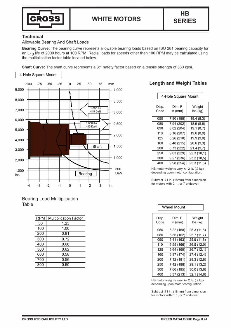
HB motor weights vary +/- 2 lb. (.9 kg) depending upon motor configuration.
Subtract .71 in. (18mm) from dimension for motors with 0, 1, or 7 endcover.
HB motor weights vary +/- 2 lb. (.9 kg) depending upon motor configuration.
Subtract .71 in. (18mm) from dimension for motors with 0, 1, or 7 endcover.
Length and Weight Tables
TechnicalAllowable Bearing And Shaft LoadsBearing Curve: The bearing curve represents allowable bearing loads based on ISO 281 bearing capacity for an L10 life of 2000 hours at 100 RPM. Radial loads for speeds other than 100 RPM may be calculated using the multiplication factor table located on page 8.44.
Shaft Curve: The shaft curve represents a 3:1 safety factor based on a tensile strength of 330 kpsi.
WHITE MOTORS
CROSS HYDRAULICS PTY LTD GREEN CATALOGUE Page 8.44
HBSERIES
HB motor weights vary +/- 2 lb. (.9 kg) depending upon motor configuration.
Subtract .71 in. (18mm) from dimension for motors with 0, 1, or 7 endcover.
HB motor weights vary +/- 2 lb. (.9 kg) depending upon motor configuration.
Subtract .71 in. (18mm) from dimension for motors with 0, 1, or 7 endcover.
Length and Weight Tables
TechnicalAllowable Bearing And Shaft LoadsBearing Curve: The bearing curve represets allowable bearing loads based on ISO 281 bearing capacity for an L10 life of 2000 hours at 100 RPM. Radial loads for speeds other than 100 RPM may be calculated using the multiplication factor table located below.
Shaft Curve: The shaft curve represents a 3:1 safety factor based on a tensile strength of 330 kpsi.
Disp. Dim. F WeightCode in (mm) lbs (kg)
050 7.80 (198) 18.4 (8,3)080 7.94 (202) 18.9 (8,6)090 8.02 (204) 19.1 (8,7)110 8.16 (207) 19.6 (8,9)125 8.26 (210) 19.9 (9,0)160 8.48 (215) 20.6 (9,3)200 8.73 (222) 21.4 (9,7)250 9.03 (229) 22.3 (10,1)300 9.27 (236) 23.2 (10,5)400 9.98 (254) 25.3 (11,5)
RPM Multiplication Factor50 1.23100 1.00200 0.81300 0.72400 0.66500 0.62600 0.58700 0.56800 0.50
Disp. Dim. E WeightCode in (mm) lbs (kg)
050 6.22 (158) 25.3 (11,5)080 6.36 (162) 25.7 (11,7)090 6.41 (163) 25.9 (11,8)110 6.55 (166) 26.5 (12,0)125 6.64 (169) 26.7 (12,1)160 6.87 (174) 27.4 (12,4)200 7.12 (181) 28.3 (12,8)250 7.42 (188) 29.1 (13,2)300 7.66 (195) 30.0 (13,6)400 8.37 (213) 32.1 (14,6)
Wheel Mount
4-Hole Square Mount
4-Hole Square Mount
Bearing
Shaft
1,000 lbs445 DaN
1,000 lbs445 DaN
500DaN
1,000
1,500
2,000
2,500
3,000
3,500
4,000
-100 -75 -50 -25 0 25 50 75 mm
1,000lbs.
2,000
3,000
4,000
5,000
6,000
7,000
8,000
9,000
-4 -3 -2 -1 0 1 2 3 in.
Bearing Load MultiplicationTable
WHITE MOTORS
CROSS HYDRAULICS PTY LTD GREEN CATALOGUE Page 8.45
HBSERIES
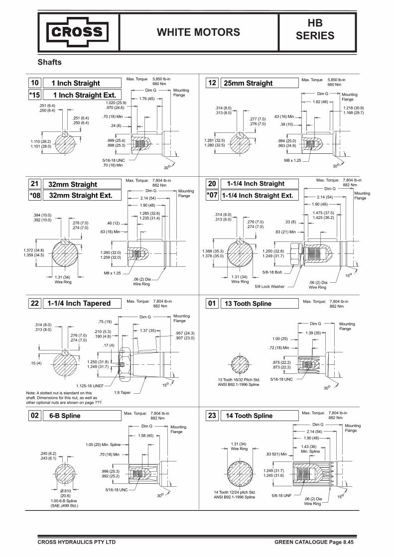
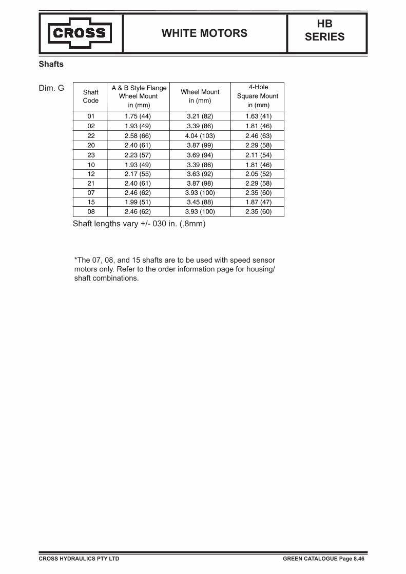
Shafts
10
21
12
20
22 01
02 23
*07
*151 Inch Straight1 Inch Straight Ext.
.251 (6.4)
.250 (6.4)
.251 (6.4)
.250 (6.4)
1.110 (28.2)1.101 (28.0)
Dim G
1.76 (45)
MountingFlange
1.020 (25.9).970 (24.6)
.70 (18) Min
.24 (6)
.999 (25.4)
.998 (25.3)
5/16-18 UNC.70 (18) Min
30o
Max. Torque 5,850 lb-in660 Nm 25mm Straight
.314 (8.0)
.313 (8.0).277 (7.0).276 (7.0)
1.281 (32.5)1.280 (32.5)
M8 x 1.25
.984 (25.0)
.983 (24.9)
.38 (10)
.63 (16) Min
1.82 (46)
Dim G
1.218 (30.9)1.168 (29.7)
30o
MountingFlange
Max. Torque 5,850 lb-in660 Nm
*0832mm Straight32mm Straight Ext.
.394 (10.0)
.392 (10.0).276 (7.0).274 (7.0)
1.31 (34)Wire Ring
1.372 (34.8)1.359 (34.5)
Dim G
2.14 (54)
1.90 (48)
1.285 (32.6)1.235 (31.4)
MountingFlange
.46 (12)
.63 (16) Min
1.260 (32.0)1.259 (32.0)
M8 x 1.25.06 (2) DiaWire Ring
1-1/4 Inch Straight
1-1/4 Inch Straight Ext.
.314 (8.0)
.313 (8.0) .276 (7.0).274 (7.0)
1.388 (35.3)1.376 (35.0)
1.31 (34)Wire Ring
Max. Torque: 7,804 lb-in882 Nm
Max. Torque: 7,804 lb-in882 Nm
Dim G
2.14 (54)
1.90 (48)
1.475 (37.5)1.425 (36.2)
.33 (8)
.83 (21) Min
1.250 (32.8)1.249 (31.7)
5/8-18 Bolt
5/8 Lock Washer.06 (2) DiaWire Ring
15o
1-1/4 Inch TaperedDim G
1.37 (35)
MountingFlange
.957 (24.3)
.907 (23.0)
15o
1:8 Taper
1.125-18 UNEF
1.250 (31.8)1.249 (31.7)
.17 (4)
.210 (5.3)
.190 (4.8)
.75 (19).314 (8.0).313 (8.0)
.276 (7.0)
.274 (7.0)
.15 (4)
Note: A slotted nut is standard on thisshaft. Dimensions for this nut, as well asother optional nuts are shown on page ???
13 Tooth SplineMax. Torque: 7,804 lb-in882 Nm
MountingFlange
Max. Torque: 7,804 lb-in882 Nm
Dim G
1.39 (35)
MountingFlange
1.00 (25)
.72 (18) Min
.875 (22.2)
.873 (22.2)
5/16-18 UNC
30o13 Tooth 16/32 Pitch Std.ANSI B92.1-1996 Spline
Max. Torque: 7,804 lb-in882 Nm
Dim G
1.58 (40)
MountingFlange
30o5/16-18 UNC
1.00 (25) Min. Spline
.70 (18) Min
.996 (25.3)
.992 (25.2)
.245 (6.2)
.243 (6.1)
O.810(20.6)
1.00-6-B Spline(SAE J499 Std.)
6-B Spline 14 Tooth Spline Max. Torque: 7,804 lb-in882 Nm
Dim G
2.14 (54)1.90 (48)
1.43 (36)Min. Spline
MountingFlange
15o.06 (2) DiaWire Ring
5/8-18 UNF
.83 921) Min
1.249 (31.7)1.245 (31.6)
1.31 (34)Wire Ring
14 Tooth 12/24 pitch Std.ANSI B92.1-1996 Spline
WHITE MOTORS
CROSS HYDRAULICS PTY LTD GREEN CATALOGUE Page 8.46
HBSERIES
Shafts
Dim. G
01 1.75 (44) 3.21 (82) 1.63 (41)
02 1.93 (49) 3.39 (86) 1.81 (46)
22 2.58 (66) 4.04 (103) 2.46 (63)20 2.40 (61) 3.87 (99) 2.29 (58)
23 2.23 (57) 3.69 (94) 2.11 (54)
10 1.93 (49) 3.39 (86) 1.81 (46)12 2.17 (55) 3.63 (92) 2.05 (52)21 2.40 (61) 3.87 (98) 2.29 (58)07 2.46 (62) 3.93 (100) 2.35 (60)15 1.99 (51) 3.45 (88) 1.87 (47)08 2.46 (62) 3.93 (100) 2.35 (60)
ShaftCode
A & B Style FlangeWheel Mount
in (mm)
Wheel Mountin (mm)
4-HoleSquare Mount
in (mm)
Shaft lengths vary +/- 030 in. (.8mm)
*The 07, 08, and 15 shafts are to be used with speed sensor motors only. Refer to the order information page for housing/shaft combinations.

WHITE MOTORS
CROSS HYDRAULICS PTY LTD GREEN CATALOGUE Page 8.47
HBSERIES
PortingEnd Ports
?
?
A A
B
B
A
D?
D?
21
5
1/2 BSP.F with 1/4 Drain7/8 O-Ring with 7/16 Drain
Aux.View A
.75 (19)1.12 (28)
Aux.View A
Aux.View B
.20 (5)
1.12 (28)
.75 (19)
67
1-1/16 O-Ring with 7/16 Drain1/2 BSP.F with 1/4 Drain
.50 (13)
.97(24)
B
Aux.View A
BA
.97 (24)
Auxillary Views
Aux. View ACase Drain.47 (12)
1.13 (29)
.55 (14)
Aux. View BValve Cavity
The 1 & 2 porting options can be ordered with an internal drain and/or a relief valve cavity.
The 6 & 7 porting options can be ordered with an internal drain.
9/16 O-Ring with 7/16 Drain
1.22 (31).85 (22).52 (13)
.72 (18)
.19 (5)
.66 (17)
A
B
A
BAux.View A
Aux.View B
D - 10 Series/2-way Valve Cavity (7/8-14 UNF -2B)
The 5 porting option can be ordered with an internal drain or a relief valve cavity.
WHITE MOTORS
CROSS HYDRAULICS PTY LTD GREEN CATALOGUE Page 8.48
HBSERIES
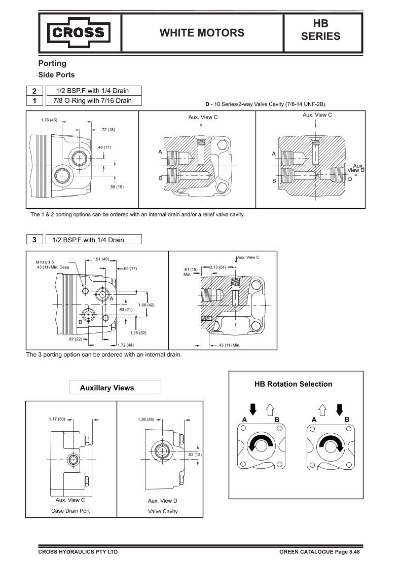
PortingSide Ports
A
B
A
B
21
1/2 BSP.F with 1/4 Drain7/8 O-Ring with 7/16 Drain
3
1.76 (45)
.72 (18)
.46 (11)
.58 (15)
Aux. View C Aux. View C
Aux.View DD
D - 10 Series/2-way Valve Cavity (7/8-14 UNF-2B)
The 1 & 2 porting options can be ordered with an internal drain and/or a relief valve cavity.
1/2 BSP.F with 1/4 Drain
Auxillary Views
1.36 (35)
.53 (13)
Aux. View D
Valve Cavity
Aux. View C
Case Drain Port
1.17 (30)
.87 (22)1.72 (44)
1.26 (32)
.83 (21)1.66 (42)
.65 (17)
1.91 (49)M10 x 1.5.43 (11) Min. Deep
B
A
.43 (11) Min.
2.13 (54).61 (15)Min.
Aux. View C
The 3 porting option can be ordered with an internal drain.
A B A B
HB Rotation Selection

WHITE MOTORS
CROSS HYDRAULICS PTY LTD GREEN CATALOGUE Page 8.49
HBSERIES
Housing
2-Hole End Ports (S)2-Hole Side Ports (S)4-Hole End Ports (S)4-Hole Side Ports (S)
6-Hole End Ports6-Hole Side Ports2-Hole End Ports2-Hole Side Ports4-Hole End Ports4-Hole Side Ports4-Hole End Ports4-Hole Side Ports
Code
A0A7A2A8A4A9B0B7W2W8F2F8
Code
OF
D
XP*R
*R1
*R2
*R3
**Z
**Z1
**Z2
**Z3
**Z4
**Z5
**Z6
Options
No OptionsFree Turn
Internal Drain(Low Pressure)
Solid NutLock Nut
Valve Cavity1000 PSI (69 Bar)
Relief Valve Installed2000 PSI (138 Bar) Relief Valve Installed3000 PSI (207 Bar) Relief Valve Installed
50 Pulse Sensorw/4pin Connector
50 Pulse Sensor w/Male (tower) Hsg. Weather
Pack Connector30 Pulse Sensorw/4pin Connector
30 Pulse Sensor w/Male (tower) Hsg. Weather
Pack Connector30 Pulse Sensor
w/Female (shroud) Hsg. Weather Pack Connector
100 Pulse Sensorw/4pin Connector 100 Pulse Sensor
w/Male (tower) Hsg. Weather Pack Connector
* Available with end ports 1& 2 and side ports 1, 2, & 5
** Available with A0, A2, A7, & A8 housings only and must use speedsensor shafts
(S) Speed Sensor Components
Code
5
6
7
1
2
3
Side Ports
9/16" O-ring1800 Ports
1-1/16" O-ring1800 Ports1/2" BSP.FOffset Ports7/8" O-ringOffset Ports1/2" BSP.F
Manifold Ports1/2" BSP.F
Code
1
2
End Ports
Aligned Ports7/8" O-ring
Aligned Ports1/2" BSP.F
Shafts
13 Tooth Spline
6-B Spline
1-1/4" Tapered
1-1/4" Straight
14 Tooth Spline
1" Straight
25mm Straight
32mm Straight
1-1/4" Straight (S)
1" Straight (S)
32mm Straight (S)
Code
01
02
22
20
23
10
12
21
07
15
08
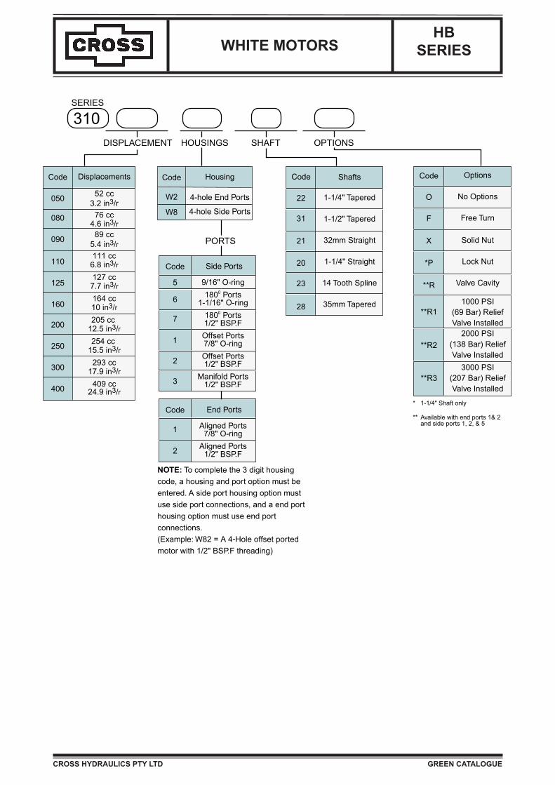
DISPLACEMENT
300SHAFT OPTIONSHOUSINGS
PORTS
SERIES
Code
050
080
090
110
125
160
200
250
300
400
Displacements
52 cc3.2 in3/r
76 cc4.6 in3/r
89 cc5.4 in3/r111 cc
6.8 in3/r127 cc
7.7 in3/r164 cc10 in3/r205 cc
12.5 in3/r254 cc
15.5 in3/r293 cc
17.9 in3/r409 cc
24.9 in3/r
NOTE: To complete the 3 digit housing code, a housing and port option must be entered. A side port housing option must use side port connections, and a end port housing option must use end port connections. (Example: W82 = A 4-Hole offset ported motor with 1/2" BSP.F threading)
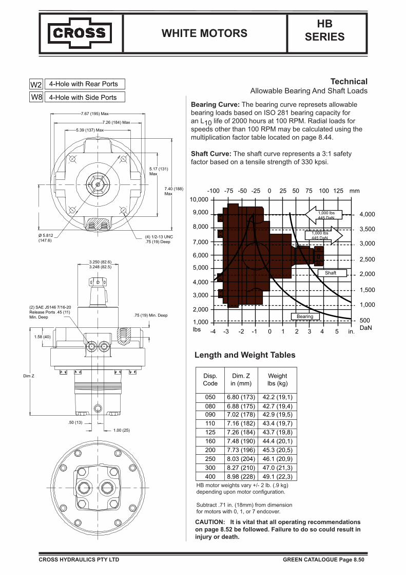
Disp. Dim. Z WeightCode in (mm) lbs (kg)
050 6.80 (173) 42.2 (19,1)080 6.88 (175) 42.7 (19,4)090 7.02 (178) 42.9 (19,5)110 7.16 (182) 43.4 (19,7)125 7.26 (184) 43.7 (19,8)160 7.48 (190) 44.4 (20,1)200 7.73 (196) 45.3 (20,5)250 8.03 (204) 46.1 (20,9)300 8.27 (210) 47.0 (21,3)400 8.98 (228) 49.1 (22,3)
W2W8
4-Hole with Rear Ports
4-Hole with Side Ports
7.67 (195) Max
7.26 (184) Max
5.39 (137) Max
5.17 (131)Max
7.40 (188)Max
(4) 1/2-13 UNC.75 (19) Deep
O 5.812(147.6)
3.250 (82.6)3.248 (82.5)
(2) SAE J5146 7/16-20Release Ports .45 (11)Min. Deep
1.58 (40)
Dim Z
.75 (19) Min. Deep
.50 (13)
1.00 (25)
1,000 lbs445 DaN
1,000 lbs445 DaN
Shaft
Bearing
-4 -3 -2 -1 0 1 2 3 4 5 in.
500DaN
1,000
1,500
2,000
2,500
3,000
3,500
4,000
-100 -75 -50 -25 0 25 50 75 100 125 mm
1,000lbs
2,000
3,000
4,000
5,000
6,000
7,000
8,000
9,000
10,000
WHITE MOTORS
CROSS HYDRAULICS PTY LTD GREEN CATALOGUE Page 8.50
HBSERIES
HB motor weights vary +/- 2 lb. (.9 kg) depending upon motor configuration.
Subtract .71 in. (18mm) from dimension for motors with 0, 1, or 7 endcover.
Length and Weight Tables
TechnicalAllowable Bearing And Shaft Loads
Bearing Curve: The bearing curve represets allowable bearing loads based on ISO 281 bearing capacity for an L10 life of 2000 hours at 100 RPM. Radial loads for speeds other than 100 RPM may be calculated using the multiplication factor table located on page 8.44.
Shaft Curve: The shaft curve represents a 3:1 safetyfactor based on a tensile strength of 330 kpsi.
CAUTION: It is vital that all operating recommendations on page 8.52 be followed. Failure to do so could result in injury or death.

WHITE MOTORS
CROSS HYDRAULICS PTY LTD GREEN CATALOGUE Page 8.51
HBSERIES
Shafts
20 1-1/4 Inch Straight
.314 (8.0)
.313 (8.0)
1.388 (35.3)1.376 (35.0)
1.33 (34)Wire Ring
.276 (7.0)
.274 (7.0).83 (21) Min.
.32 (8)
1.250 (31.8)1.249 (31.7)
5/8-18 UNF .06 (2) Dia.Wire Ring
1.90 (48)
2.14 (54)
*4.19 (106)
Max. Torque 7,804 lb-in882 Nm
MountingFlange
1.475 (37.5)1.425 (36.2)
.394 (10)
.392 (10).276 (7.0).274 (7.0)
.53 (13)
.63 (16)
1.259 (32.0)1.258 (32.0)
M8 x 1.25
30o
1.235 (31.4)1.285 (32.6)
MountingFlange
*3.96 (101)
2.14 (54)
1.89 (48)
Max. Torque 7,804 lb-in882 Nm
.314 (8.0)
.313 (8.0).276 (7.0).274 (7.0)
.15 (4) 1.500 (38.1)1.499 (38.1)
.17 (4)
.75 (19)
*4.56 (116)
1.72 (44)
.20 (5)
1:8 Taper
1.125-18UNEFSlotted Hex NutTorque To 300-400Ft. Lbs.Note: A slotted nut is
standard on this shaft.
1.475 (37.5)1.425 (36.2)
.15 (4)
.314 (8.0)
.313 (8.0).276 (7.0).274 (7.0)
1.250 (31.8)1.248 (31.7)
.17 (4)
1:8 Taper
.957 (24.3)
.907 (23.0)
1.36 (35)
*4.18 (106)
Max. Torque 7,804 lb-in882 Nm22 1-1/4 Tapered 31 1-1/2 Tapered
23 14 Tooth Spline28 35mm Tapered
21 32mm Straight
.15 (3.8)
.314 (8.0)
.313 (8.0).276 (7.0).274 (7.0)
1.378 (35.0)1.358 (34.5)
M24 x 1.5 Thread
1:10 Taper
.19 (5)
.12 (3)
.87 (22)1.42 (36)
*4.20 (107) MountingFlange
.900 (22.9)
.890 (22.6)
1.33 (34)Wire Ring
14 Tooth 12/24Pitch Std. ANSIB92.1-1996 Spline
.83 (21)
1.249 (31.7)1.245 (31.6)
5/8-18 UNF.06 (2) Dia.Wire Ring
1.60 (41)Min. Spline
1.90 (48)
*4.19 (106) MountingFlange
Max. Torque 7,804 lb-in882 Nm
Max. Torque 7,804 lb-in882 Nm
Max. Torque 7,804 lb-in882 Nm
*Note: Shaft lengths may vary by +/- .030 (.8mm)
.76 (19)
.20 (5)
30o
Note: A slotted nut isstandard on this shaft.
Technical Operating SpecificationsRated brake torque: .......................8,000 lb-in (904 Nm)Initial release pressure ......................... 300 psi (21 bar)Full release pressure ............................ 450 psi (31 bar)Maximum release pressure ............. 3,000 psi (207 bar)Release volume .............................8-10 cu.in. (13-16cc)
WHITE MOTORS
CROSS HYDRAULICS PTY LTD GREEN CATALOGUE Page 8.52
HBSERIES
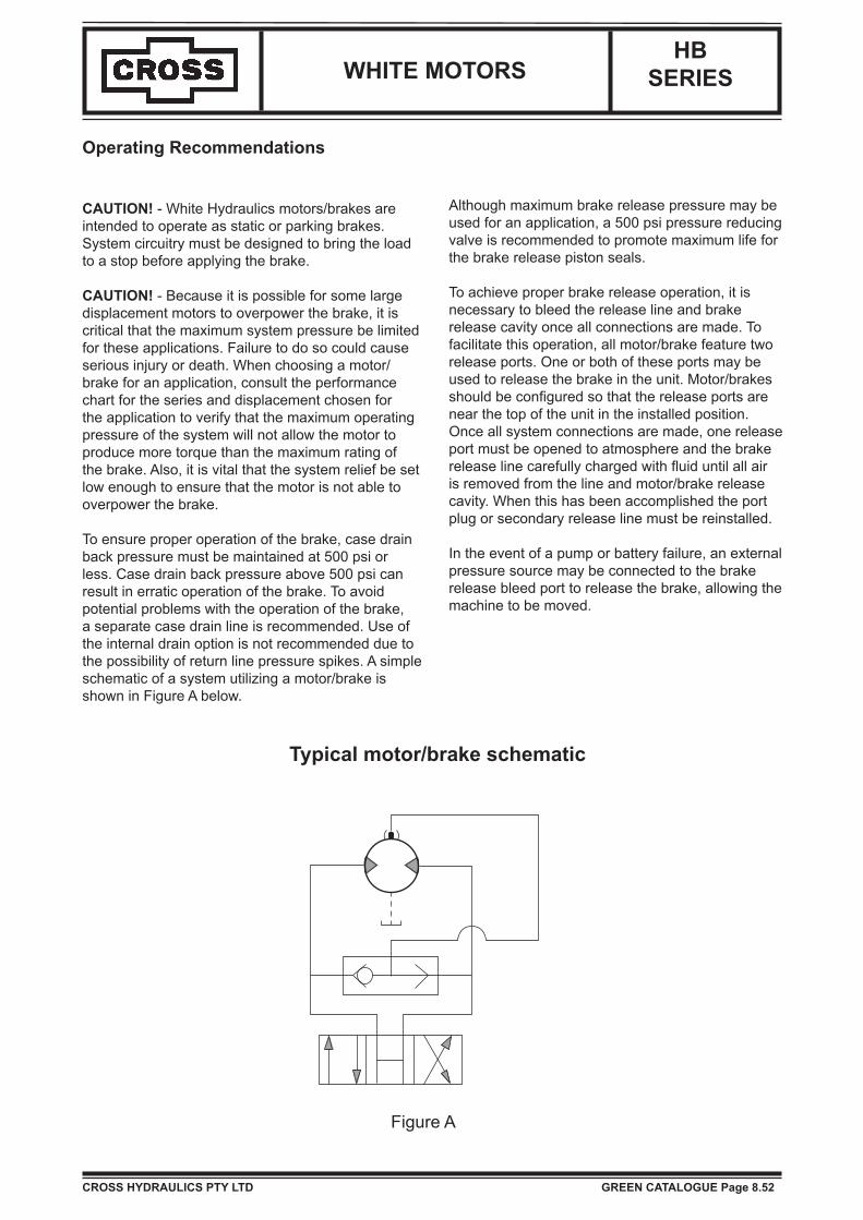
Operating Recommendations
CAUTION! - White Hydraulics motors/brakes are intended to operate as static or parking brakes. System circuitry must be designed to bring the load to a stop before applying the brake.
CAUTION! - Because it is possible for some large displacement motors to overpower the brake, it is critical that the maximum system pressure be limited for these applications. Failure to do so could cause serious injury or death. When choosing a motor/brake for an application, consult the performance chart for the series and displacement chosen for the application to verify that the maximum operating pressure of the system will not allow the motor to produce more torque than the maximum rating of the brake. Also, it is vital that the system relief be set low enough to ensure that the motor is not able to overpower the brake.
To ensure proper operation of the brake, case drain back pressure must be maintained at 500 psi or less. Case drain back pressure above 500 psi can result in erratic operation of the brake. To avoid potential problems with the operation of the brake, a separate case drain line is recommended. Use of the internal drain option is not recommended due to the possibility of return line pressure spikes. A simple schematic of a system utilizing a motor/brake is shown in Figure A below.
Although maximum brake release pressure may be used for an application, a 500 psi pressure reducing valve is recommended to promote maximum life for the brake release piston seals.
To achieve proper brake release operation, it is necessary to bleed the release line and brake release cavity once all connections are made. To facilitate this operation, all motor/brake feature two release ports. One or both of these ports may be used to release the brake in the unit. Motor/brakes should be configured so that the release ports are near the top of the unit in the installed position. Once all system connections are made, one release port must be opened to atmosphere and the brake release line carefully charged with fluid until all air is removed from the line and motor/brake release cavity. When this has been accomplished the port plug or secondary release line must be reinstalled.
In the event of a pump or battery failure, an external pressure source may be connected to the brake release bleed port to release the brake, allowing the machine to be moved.
Figure A
Typical motor/brake schematic
WHITE MOTORS
CROSS HYDRAULICS PTY LTD GREEN CATALOGUE
HBSERIES
Housing
4-hole End Ports
4-hole Side Ports
Code
W2
W8
Code
O
F
X
*P
**R
**R1
**R2
**R3
Options
No Options
Free Turn
Solid Nut
Lock Nut
Valve Cavity
1000 PSI(69 Bar) ReliefValve Installed
2000 PSI(138 Bar) Relief Valve Installed
3000 PSI(207 Bar) Relief Valve Installed
* 1-1/4" Shaft only
** Available with end ports 1& 2 and side ports 1, 2, & 5
Shafts
1-1/4" Tapered
1-1/2" Tapered
32mm Straight
1-1/4" Straight
14 Tooth Spline
35mm Tapered
Code
22
31
21
20
23
28
Code
5
6
7
1
2
3
Side Ports
9/16" O-ring1800 Ports
1-1/16" O-ring1800 Ports1/2" BSP.FOffset Ports7/8" O-ringOffset Ports1/2" BSP.F
Manifold Ports1/2" BSP.F
Code
1
2
End Ports
Aligned Ports7/8" O-ring
Aligned Ports1/2" BSP.F
PORTS
NOTE: To complete the 3 digit housing code, a housing and port option must be entered. A side port housing option must use side port connections, and a end port housing option must use end port connections. (Example: W82 = A 4-Hole offset ported motor with 1/2" BSP.F threading)
DISPLACEMENT
310SHAFT OPTIONSHOUSINGS
SERIES
Code
050
080
090
110
125
160
200
250
300
400
Displacements
52 cc3.2 in3/r
76 cc4.6 in3/r
89 cc5.4 in3/r111 cc
6.8 in3/r127 cc
7.7 in3/r164 cc10 in3/r205 cc
12.5 in3/r254 cc
15.5 in3/r293 cc
17.9 in3/r409 cc
24.9 in3/r

WHITE MOTORS
CROSS HYDRAULICS PTY LTD GREEN CATALOGUE
HBSERIES
HB (312) Series
WARNING AND DISCLAIMER OF WARRANTIES, LIABILITY AND REMEDIES: Due to the special tools, fixtures and test equipment required to properly service the brake portion of thisproduct, it is highly recommended that all motor/brakes be returned to the factory for repair. White Hydraulics accepts no responsibility for repairs performed by anyone other than WhiteHydraulics factory service personnel. TO THE EXTENT THAT ANY MOTOR/BRAKE IS REPAIRED BY ANYONE OTHER THAN WHITE HYDRAULICS, WHITE HYDRAULICS DISCLAIMS ANYWARRANTIES ON THE PRODUCTS. WHITE HYDRAULICS DISCLAIMS ANY AND ALL LIABILITY FOR DAMAGES BASED IN ANY WAY UPON PRODUCTS THAT HAVE BEEN REPAIRED BYANYONE OTHER THAN WHITE HYDRAULICS. IN THE EVENT A PRODUCT REPAIRED BY ANYONE OTHER THAN WHITE HYDRAULICS FAILS, WHITE HYDRAULICS SHALL NOT BELIABLE FOR ANY INCIDENTAL OR CONSEQUENTIAL DAMAGES RELATED IN ANY WAY TO ANY FAILURE OF THE PRODUCT OR THE REPAIRS. To inquire about repairs and obtain returnauthorization for a product, please contact the technical support department at (03) 9544-5155.

WHITE MOTORS
CROSS HYDRAULICS PTY LTD GREEN CATALOGUE
HBSERIES
NIRAEBTFAHSTNORFMIHSPUKCABLATEM GTEFLON BACKUP SEAL THRUST WASHERSHAFT SEAL THRUST BEARINGSMALL O-RING PISTON SEAL FRICTIONS DISKS AND STAMPINGSSMALL TEFLON PISTON SEAL PISTONLARGE O-RING PISTON SEAL SPRINGS (25)LARGE TEFLON PISTON SEAL REAR SHAFT BEARINGO-RING SEAL SPACER SHIM(S)
)8(SWERCSPAC)4(SLAESYDOBCOMMUTATOR SEAL MANIFOLDPISTON O-RING SEAL COMMUTATOR ASSEMBLYPISTON TEFLON SEAL ENDCOVER PISTON
PISTON SPRING1000 PSI RELIEF VALVE2000 PSI RELIEF VALVE3000 PSI RELIEF VALVE1.00-20 UNEF SLOTTED NUT1.00-20 UNEF SOLID NUT1.00-20 UNEF LOCK NUT1.125-18 UNEF SLOTTED NUT1.125-18 UNEF SOLID NUT
ROTORS, DRIVE LINKS AND BOLTSWHEN CHANGING MOTOR DISPLACEMENTS, A MATCHING ROTOR, DRIVE LINK AND BOLT SET KIT MUST BE ORDERED
HOUSING KITS
#W2 & W8- HOUSING WITH TOP RELEASE PORTSREAR HOUSING
SHAFTS AND RELATED COMPONENTS KITSSHAFT KITS COME WITH RELATED SHAFT COMPONENTS (i.e. keys, nuts, etc.)TO ORDER INDIVIDUAL SHAFT COMPONENTS (i.e. keys, nuts, bolts, washers or wire rings) USE THE KIT NUMBER FOR EACH INDIVIDUAL PART
#22- 1-1/4" TAPERED#31- 1-1/2" TAPERED#28- 35MM TAPERED#21- 32MM STRAIGHT#20- 1-1/4" STRAIGHT#23- 1-1/4" 14 TOOTH SPLINE
ENDCOVER KITS (EXPLODED VIEW ITEM #31)ENDCOVER KITS COME ASSEMBLED WITH EXPLODED VIEW ITEMS # 11, 12, 29, & 30TO ORDER A RELIEF VALVE FOR THE VALVE CAVITY ENDCOVERS, SEE THE MISCELLANEOUS KITS LISTING ABOVE FOR RELIEF VALVE KIT #'S
#5- 9/16" O-RING SIDE PORTS#6- 1-1/16" O-RING SIDE PORTS#7- 1/2" BSP.F SIDE PORTS#2- 1/2" BSP.F REAR PORTS#9- 3/8" BSP.F SIDE PORTS#1- 7/8" O-RING OFFSET PORTS#1- 7/8" O-RING REAR PORTS#2- 1/2" BSP.F OFFSET PORTS#3- 1/2" BSP.F OFFSET MANIFOLD PORTS
300015008300012013
700018088
910018011300018068200018074
910018014
---
---------
300339301
300018056300018059500018228500018231
500449201
------------
300339302---
---
300332003300332004300332005300332006300332008300332010
---
300160002300160003
500018203300018002300018003300018088
---
320 300332020300332024
300332020F
---------300160004
300160006
STIKSUOENALLECSIM257333003TIKLAESDESCRIPTION
EXP. VIEWITEM # NOITPIRCSEDTIK
EXP. VIEWITEM #
3121-1#SMETI151NIDEDULCNI2
6 20
3 SEAL KIT 164 17 & 18300333752
12 29
9 2410 27
HB (312) SERIES MOTOR BRAKE COMPONENTS
KIT
11 28
7 218 22
5 19
300334006L300334008L300334010L
30
300339303P700018038700018054
3636
STANDARD ROTOR KIT FREETURN ROTOR KIT
526262
DRIVE LINK KIT
300332003F050 300014028
EXPLODED VIEW ITEM #
080
DISPLACEMENT
500233003090 F 300014028 300334005300332006F 300014029 300334006110
800233003521 F 300014029 300334008
250 300332014
300332010F 300014030200 300332012 300332012F 300014030
300014027
160
300 300332018 300332018F 300014027
450
DESCRIPTIONEXPLODED VIEW
ITEM #HOUSING KIT
300332024F 300014031 300334024
EXPLODED VIEW ITEM # 34 35 36DESCRIPTION SHAFT KIT KEY KIT
DESCRIPTIONSTANDARD
ENDCOVER KIT
300110074300110075
300339101---
300110067
VALVE CAVITYENDCOVER KIT
300160000 300160000R---100061003
300160007R---
300160007300160008300160009
300332004F 300014028
300014031
300013027
300110063300110064300110079
NOT SHOWN
NOT SHOWNNOT SHOWNNOT SHOWN
3636
300334003L300334004L
300334012L300334014L
2314
WIRE RING KIT
300334003300334004
300334024
300130046
300334012
300334018300332014F
300339101500449102500449104300339103
---
33BOLT SET KIT FOR
ENDCOVERS WITH OFFSETPORTS
33
BOLT SET KIT
300334018L300334024L300334024L
300334010
300334005L
NUT KIT
KITS LISTABOVE
------
500449201SEE MISC.
500449201
NOT SHOWNNOT SHOWNWASHER KIT BOLT KIT
500018221500449304500449303
36
300334014

WHITE MOTORS
CROSS HYDRAULICS PTY LTD GREEN CATALOGUE
HBSERIES

WHITE MOTORS
CROSS HYDRAULICS PTY LTD GREEN CATALOGUE
HBSERIES
DUST SEAL SEAL CARRIERWIRE RING THRUST WASHER
GNIRAEBTSURHTMIHSPUKCABLATEMGNIRAEBRELLORLAESERUSSERPHGIHRECAPSGNIRAEBMIHSPUKCABLATEM
ETALPRAEWLAESPUKCABNOLFETSHAFT SEAL MANIFOLDBODY SEALS (5) COMMUTATOR ASSEMBLY
LBMSAROTATUMMOCTNUOMDIMLAESROTATUMMOC YO-RING SEAL ENDCOVER PISTON
GNIRPSNOTSIPLAESPUKCABNOLFET1000 PSI RELIEF VALVE2000 PSI RELIEF VALVE3000 PSI RELIEF VALVE1.00-20 UNEF SLOTTED NUT1.00-20 UNEF SOLID NUTPORT PLUG ("???AB" OPTION)1.00-20 UNEF LOCK NUT
ROTORS, DRIVE LINKS AND BOLTSWHEN CHANGING MOTOR DISPLACEMENTS, A MATCHING ROTOR AND BOLT SET KIT MUST BE ORDERED. A NEW DRIVE LINK KIT MAY BE NECESSARY.
HOUSING KITS (EXPLODED VIEW ITEM #16)HOUSING KITS INCLUDE THE FRONT & REAR BEARINGS (#15), 2 THRUST WASHERS & 1 BEARING (#'S 13 & 14), & SPACER (#30) INSTALLED IN THE HOUSING.THE REAR THRUST WASHER AND THRUST BEARING ARE INCLUDED IN THE HOUSING KIT.
#M2 & M8- 4-HOLE SQUARE MOUNT (MIDMOUNT)#B0 & B7- 2-HOLE SAE B MOUNT#F2 & F8- 4-HOLE SQUARE MOUNT#A0 & A7- 2-HOLE SAE "A" SYTLE MOUNT#W2 & W8- 4-HOLE WHEEL MOUNT#A2 & A8- 4-HOLE SAE "A" STYLE MOUNT#A4 & A9- 6-HOLE SAE "A" STYLE MOUNT
SHAFTS AND RELATED COMPONENTS KITSSHAFT KITS COME WITH RELATED SHAFT COMPONENTS (i.e. keys, nuts, etc.)TO ORDER INDIVIDUAL SHAFT COMPONENTS (i.e. keys, nuts, bolts, washers or wire rings) USE THE KIT NUMBER FOR EACH INDIVIDUAL PART
#01- 13 TOOTH SPLINE#02- 6-B SPLINE#22- 1-1/4" TAPERED#20- 1-1/4" STRAIGHT#23- 14 TOOTH SPLINE#10- 1" STRAIGHT#12- 25MM STRAIGHT#21- 32MM STRAIGHT
ENDCOVER KITS (EXPLODED VIEW ITEM #24)ENDCOVER KITS COME ASSEMBLED WITH EXPLODED VIEW ITEMS # 10, 11, 22 & 23.TO ORDER A RELIEF VALVE FOR THE VALVE CAVITY ENDCOVERS, SEE THE MISCELLANEOUS KITS LISTING ABOVE FOR RELIEF VALVE KIT #'S.
#5- 9/16" O-RING SIDE PORTS#6- 1-1/16" O-RING SIDE PORTS#7- 1/2" BSP.F SIDE PORTS#2- 1/2" BSP.F REAR PORTS#9- 3/8" BSP.F SIDE PORTS#1- 7/8" O-RING OFFSET PORTS#1- 7/8" O-RING REAR PORTS#2- 1/2" BSP.F OFFSET PORTS#3- 1/2" BSP.F OFFSET MANIFOLD PORTS
#15- 1" STRAIGHT SPEED SENSOR
DESCRIPTION
#08- 32mm STRAIGHT SPEED SENSOR
------
300160008D300160009D
300160006DR300160007DR
#07- 1-1/4" STRAIGHT SPEED SENSOR
---500449201500449201
NUT KIT BOLT KIT
300130058300130059
28
---
500018231
500449303
300339303P
WASHER KIT WIRE RING KIT
---
---300339302
BOLT SET KIT FOR
300012012300015008300012013
26
500018221500449304
500018186
300160003DR
300012011300018056300018059500018228
VALVE CAVITY & INTERNALDRAIN ENDCOVER KIT
300334004L300334012300334014
300018054300018052300018053300018096
------
---300160000D------
300160001D300160002D300160003D300160004D
STANDARDENDCOVER KIT
VALVE CAVITYENDCOVER KIT
INTERNAL DRAINENDCOVER KIT
---500449201
------
300339100
29 NOT SHOWN NOT SHOWN NOT SHOWN
SEE MISC.KITS LIST
500449201
400
500449201
EXPLODED VIEW ITEM # 27DESCRIPTION SHAFT KIT KEY KIT
ABOVE
---
300
------
300339302
300335014
---
300110059
300335114
------
---
300110052------
160
---
200
---
410233003052 F300332014
---------
125
300339301------
300335114
300334014300334018
300332012
300332018
300110050
300339301------
110
300110086300110089
300339104300339103300339106
300339103
300110057
300110084
500233003090 F300332006F300332008F300332010F300332012F
300332010
080
DRIVE LINK KIT300014028300014028
300332003F300332004F
300332003300332004
26
050DISPLACEMENT
300334005300334008
2929
29NOT SHOWN
8191BOLT SET KIT
NOT SHOWN
23NOT SHOWNNOT SHOWN
9 NOT SHOWN10 22
7 208 21
6 17300333900
300110056
300339101300339106
---300339100
---
51NIDEDULCNI45 SEAL KIT 30
2 134111-1#SMETI3
EXP.VIEWITEM # KIT
1 12 300018091
DESCRIPTIONEXP. VIEW
ITEM # NOITPIRCSEDTIK
HB (300) SERIES MOTOR COMPONENTSSTIKSUOENALLECSIM009333003TIKLAES
11
TIKGNISUOHNOITPIRCSED
EXPLODED VIEW ITEM # 19STANDARD ROTOR KIT FREETURN ROTOR KIT
300332008
300160006D
------
300160007R---
300160007D
------
300160000R300160000300160001300160002300160003300160004300160006300160007300160008300160009
320
300130050300130055300130056300130057
300110053300110054300110055
300334014300334018300334012L300335110300334018L300335016300334024L300334024L
300014027
300334008300334010300334003L300334012
300332020F300332024F
300014028300014029
300014031300014031
300014029
300014027
300014030300014030
---
300332020
300332005300332006
300332024
300130055
300332018F