hazardous area installation manual - metrix-vibrationhazardous area installation manual setpoint™...
TRANSCRIPT

Hazardous Area Installation Manual
SETPOINT™ Machinery Protection System
Document 1160865 Page 1 of 53 Rev. B (Sept. 2013)
Metrix Instrument Company 8824 Fallbrook Dr. Houston, TX77064, USA Tel: 1-281-940-1802 After Hours Technical Assistance: 1-713-702-8805 Fax: 1-713-559-9421 [email protected] www.metrixvibration.com

Hazardous Area Installation Manual
SETPOINT™ Machinery Protection System
Document 1160865 Page 2 of 53 Rev. B (Sept. 2013)

Hazardous Area Installation Manual
SETPOINT™ Machinery Protection System
Document 1160865 Page 3 of 53 Rev. B (Sept. 2013)
Table of Contents
1 Important Safety Information ......................................................................................................... 6
1.1 General Safety Summary ........................................................................................................... 6
1.2 Safety Terms and Symbols ......................................................................................................... 7
2 Overview ......................................................................................................................................... 8
2.1 Warnings .................................................................................................................................... 8
2.2 Condition for safe use ................................................................................................................ 8
2.3 Enclosure .................................................................................................................................... 9
2.4 Power ......................................................................................................................................... 9
2.5 Labeling .................................................................................................................................... 10
2.5.1 Grounding........................................................................................................................ 11
2.5.2 USB Connector ................................................................................................................ 11
3 Installation .................................................................................................................................... 12
3.1 Installation Considerations ...................................................................................................... 12
3.1.1 Permanent Connection Consideration ............................................................................ 12
3.1.2 Clearance ......................................................................................................................... 12
3.1.3 Environment .................................................................................................................... 12
3.2 Mounting Methods .................................................................................................................. 13
3.2.1 Rack Mounting ................................................................................................................ 13
3.2.2 Panel Mounting ............................................................................................................... 14
3.2.3 Bulkhead Mounting ......................................................................................................... 15
3.2.4 Box Mounting .................................................................................................................. 15
3.2.5 Mounting the Display Remotely ...................................................................................... 15
3.2.6 Reverse Mounting ........................................................................................................... 16
3.3 General Wiring Considerations ................................................................................................ 17
3.4 Rack Connection ModuleConnections ..................................................................................... 19
Hazardous Area Installation Manual
SETPOINT™ Machinery Protection System
Document 1160865 Page 4 of 53 Rev. B (Sept. 2013)
3.4.1 System Chassis Ground ................................................................................................... 19
3.4.2 Single Point System Common to Chassis Connection ..................................................... 20
3.4.3 Power Wiring ................................................................................................................... 21
3.4.4 Fault Relay Wiring ........................................................................................................... 22
3.4.5 Discrete Control Input Wiring ......................................................................................... 23
3.4.6 Digital Inputs ................................................................................................................... 24
3.4.7 Buffered Outputs Connectors ......................................................................................... 25
3.4.8 Switchable BNC connectors: ........................................................................................... 27
3.5 System Access Module Connections........................................................................................ 27
3.5.1 SD Card Installation ......................................................................................................... 27
3.5.2 Modbus/TCP Ethernet Connection ................................................................................. 28
3.5.3 Ethernet Data Acquisition Computer (DAC) Connection ................................................ 29
3.6 Monitor Module Connections .................................................................................................. 30
3.6.1 Connecting to Relays ....................................................................................................... 30
3.6.2 Universal Monitoring Module (UMM) Sensor Wiring ..................................................... 32
3.6.3 Temperature Monitoring Module (TMM) Sensor Wiring ............................................... 44
4 Standards ...................................................................................................................................... 47
4.1.1 Standards for Zones ........................................................................................................ 47
4.1.2 Standards for Divisions .................................................................................................... 47
5 Maintenance ................................................................................................................................. 48
5.1 Inserting and Removing Modules ............................................................................................ 48
5.2 Removing or Installing the Door .............................................................................................. 51
5.2.1 Installing the Rack Door .................................................................................................. 51
5.2.2 Removing or Installing the Display Cable ........................................................................ 52

Hazardous Area Installation Manual
SETPOINT™ Machinery Protection System
Document 1160865 Page 5 of 53 Rev. B (Sept. 2013)
List of Figures:
Figure 1: Rack Mounting Holes ............................................................................................................. 13 Figure 2: Mounting Holes and Cutout ................................................................................................... 14 Figure 3: Bulkhead Mounting ................................................................................................................ 15 Figure 4: Reverse Mounting the Rack ................................................................................................... 16 Figure 5: Loosen Connector Flange Screws .......................................................................................... 17 Figure 6: Pull Connector Plug Out ......................................................................................................... 17 Figure 7: Chassis Jumper Installation .................................................................................................... 20 Figure 8: Chassis Jumper Removal ........................................................................................................ 20 Figure 9: Fault Relay Operation ............................................................................................................ 22 Figure 10: Discrete Contact Inputs ........................................................................................................ 23 Figure 11: Wiring Digital Inputs ............................................................................................................ 24 Figure 12: RCM Buffered Out Connectors ............................................................................................ 25 Figure 13: Connecting to Modbus......................................................................................................... 28 Figure 14: Relay Wiring ......................................................................................................................... 31 Figure 15: MX2030 Wiring .................................................................................................................... 33 Figure 16: -24 V Proximity Sensor Wiring ............................................................................................. 34 Figure 17: -24 V, 3-wire Accelerometer wiring ..................................................................................... 35 Figure 18: IEPE Transducer Wiring ........................................................................................................ 36 Figure 19: Moving Coil Velocity Sensor Wiring ..................................................................................... 37 Figure 20: Phase Trigger Wiring ............................................................................................................ 38 Figure 21: Aeroderivative Wiring .......................................................................................................... 39 Figure 22: 86517 Interface Wiring ........................................................................................................ 39 Figure 23: Magnetic Pickup Wiring ....................................................................................................... 40 Figure 24: Impact transmitter wiring .................................................................................................... 43 Figure 25: RTD Wiring ........................................................................................................................... 44 Figure 26: Thermocouple Wiring .......................................................................................................... 45 Figure 27: TMM Process Variable Transmitter Wiring .......................................................................... 46 Figure 28: Loosen Captive Screws ......................................................................................................... 49 Figure 29: Removing a Module ............................................................................................................. 49 Figure 30: Module Installation .............................................................................................................. 50 Figure 31: Door Hinge Open ................................................................................................................. 51 Figure 32: Door Hinge Locked ............................................................................................................... 51 Figure 33: Display Connector Retention Locks ..................................................................................... 52 Figure 34: Inserting the Display Cable at the SAM ............................................................................... 53

Hazardous Area Installation Manual
SETPOINT™ Machinery Protection System
Document 1160865 Page 6 of 53 Rev. B (Sept. 2013)
1 Important Safety Information
1.1 General Safety Summary Review the following safety precautions to avoid injury and prevent damage to this product or any products connected to it.
• USE ONLY AS SPECIFIED To avoid potential hazards, use this product only as specified. Only qualified personnel should perform installation and uninstallation procedures.
• CONNECT AND DISCONNECT PROPERLY Do not connect or disconnect this product while it is connected to the live power source.
• GROUND THE PRODUCT The housing of this product should be connected to earth ground. Before attempting to turn on the product, ensure its housing is properly grounded.
• OBSERVE ALL TERMINAL RATINGS To avoid fire or shock hazard, observe all ratings and markings on the product. Consult the individual sections of this manual for further ratings information before making connections to the product.
• DO NOT OPERATE WITHOUT COVER If the product has a cover or covers, do not operate with cover(s) removed.
• AVOID EXPOSURE TO CIRCUITRY Do not touch exposed electrical connections and components when power is present.
• DO NOT OPERATE WITH SUSPECT FAILURES If you suspect there is damage to this product, have it inspected by qualified personnel.
• DISCONNECTING METHOD a) a switch or circuit-breaker must be included in the installation
b) it must be suitably located and easily reached;
c) it must be marked as the disconnecting device for the equipment.
Hazardous Area Installation Manual
SETPOINT™ Machinery Protection System
Document 1160865 Page 7 of 53 Rev. B (Sept. 2013)
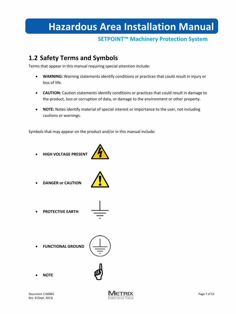
1.2 Safety Terms and Symbols Terms that appear in this manual requiring special attention include:
• WARNING: Warning statements identify conditions or practices that could result in injury or loss of life.
• CAUTION: Caution statements identify conditions or practices that could result in damage to the product, loss or corruption of data, or damage to the environment or other property.
• NOTE: Notes identify material of special interest or importance to the user, not including cautions or warnings.
Symbols that may appear on the product and/or in this manual include:
• HIGH VOLTAGE PRESENT
• DANGER or CAUTION
• PROTECTIVE EARTH
• FUNCTIONAL GROUND
• NOTE

Hazardous Area Installation Manual
SETPOINT™ Machinery Protection System
Document 1160865 Page 8 of 53 Rev. B (Sept. 2013)
2 Overview
This manual contains information on installing a Setpoint Machinery Protection System (MPS) in a hazardous area. This manual supplements the Setpoint MPS Operation and Maintenance Manual (1079330).
2.1 Warnings • THIS EQUIPMENT IS SUITABLE FOR USE IN CLASS I, DIVISION 2, GROUPS A, B, C, D OR NON-
HAZARDOUS LOCATIONS ONLY; • WARNING - EXPLOSION HAZARD – SUBSTITUTION OF COMPONENTS MAY IMPAIR
SUITABILITY FOR CLASS I, DIVISION 2; • AVERTISSEMENT - RISQUE D'EXPLOSION – LA SUBSTITUTIOND E COMPOSANTSP EUTR
ENDRE CE MATERIEL INACCEPTABLE POUR LES EMPLACEMENTS DE CLASSE I, DIVISION 2”; • WARNING - EXPLOSION HAZARD - DO NOT DISCONNECT EQUIPMENT UNLESS POWER HAS
BEEN SWITCHED OFF OR THE AREA IS KNOWN TO BE NONHAZARDOUS”; • AVERTISSEMENT - RISQUE D'EXPLOSION - AVANT DE DECONNECTER L'EQUIPEMENT,
COUPER LE COURANT OU S'ASSURER QUE L'EMPLACEMENT EST DESIGNE NON”; • Warning – EXPLOSION HAZARD - Do not use USB connectors in hazardous area; • AVERTISSEMENT – RISQUE D’EXPLOSION – Ne pas utiliser les connecteurs USB en zone
dangereuse; • Warning – EXPLOSION HAZARD - Do not service when an explosive atmosphere is present; • AVERTISSEMENT - RISQUE D’EXPLOSION – Ne pas réparer en présence d’une atmosphère
explosive;
2.2 Condition for safe use • THIS EQUIPMENT MUST BE INSTALLED INSIDE A CERTIFIED IECEx Ex e or ATEX Ex e IP54
ENCLOSURE • THIS EQUIPMENT IS TO BE CONNECTED TO A CERTIFIED ISOLATED SELV POWER SOURCE; • TRANSIENT PROTECTION SHALL BE PROVIDED ON THE SUPPLY TO LIMIT TRANSIENTS TO
MAXIMUM OF 50.4Vpk; • USB CONNECTORS ARE NOT FOR USE IN HAZARDOUS AREA AND WILL BE INTERNAL TO
INSTALLATION IN IECEx Ex e CERTIFIED IP54 ENCLOSURE;

Hazardous Area Installation Manual
SETPOINT™ Machinery Protection System
Document 1160865 Page 9 of 53 Rev. B (Sept. 2013)
2.3 Enclosure When installing in hazardous areas, install the Setpoint system in an enclosure or area protected to IP54 (splash protected).
The MX2020 shall be installed in a suitably-certified enclosure which provides at least an ingress protection level of IP54, over the operating temperature range plus the applicable thermal rise and safety margins as described in clause 13 of IEC/EN 60079-15.
2.4 Power The Setpoint MPS must be powered by a 24-Vdc power by an isolated SELV supply which has been certified for use in a Zone 2/Division 2 location. The Metrix supplied power supplies meet this requirement.
In the event the external, 24 Vdc power supply does not clamp the output voltage to less than 140% of the rated maximum voltage, the installer will fit a suitably-certified over-voltage protection device between the power supply and the Setpoint MPS.
Maximum power consumed by the Setpoint rack is 128W.
Maximum current drawn by the Rack (without sensors attached): 5.3A
Maximum power consumed by sensors connected to Setpoint: 2W/monitor
Maximum electrical ratings of the system (Rack including sensors) are as follows: Voltage: Continuous duty: 22- 30VDC
Intermittent / Excursions to: 18-36 Vdc Current: 8.0 A Expected power budget of supply: 160 W
The external power supplies are powered from high voltages. Only qualified personnel should make connections to the power supply. Refer to instructions included with the power supply module.
Hazardous Area Installation Manual
SETPOINT™ Machinery Protection System
Document 1160865 Page 10 of 53 Rev. B (Sept. 2013)
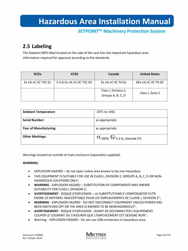
2.5 Labeling The Setpoint MPS label located on the side of the rack lists the important hazardous area information required for approval according to the standards.
IECEx ATEX Canada United States
Ex nA nC IIC T3C Gc II 3 G Ex nA nC IIC T3C GC Ex nA nC IIC T4 Gc AEx nA nC IIC T4 GC
Class I, Division 2, Groups A, B, C, D
Class I, Zone 2
Ambient Temperature -20°C to +65C
Serial Number: as appropriate
Year of Manufacturing: as appropriate
Other Markings: 0976 II 3 G, Intertek ETL
Warnings located on outside of main enclosure (separately supplied):
WARNING:
• EXPLOSION HAZARD – do not open unless area known to be non-hazardous • THIS EQUIPMENT IS SUITABLE FOR USE IN CLASS I, DIVISION 2, GROUPS A, B, C, D OR NON-
HAZARDOUS LOCATIONS ONLY; • WARNING - EXPLOSION HAZARD – SUBSTITUTION OF COMPONENTS MAY IMPAIR
SUITABILITY FOR CLASS I, DIVISION 2; • AVERTISSEMENT - RISQUE D'EXPLOSION – LA SUBSTITUTIOND E COMPOSANTSP EUTR
ENDRE CE MATERIEL INACCEPTABLE POUR LES EMPLACEMENTS DE CLASSE I, DIVISION 2”; • WARNING - EXPLOSION HAZARD - DO NOT DISCONNECT EQUIPMENT UNLESS POWER HAS
BEEN SWITCHED OFF OR THE AREA IS KNOWN TO BE NONHAZARDOUS”; • AVERTISSEMENT - RISQUE D'EXPLOSION - AVANT DE DECONNECTER L'EQUIPEMENT,
COUPER LE COURANT OU S'ASSURER QUE L'EMPLACEMENT EST DESIGNE NON”; • Warning – EXPLOSION HAZARD - Do not use USB connectors in hazardous area;

Hazardous Area Installation Manual
SETPOINT™ Machinery Protection System
Document 1160865 Page 11 of 53 Rev. B (Sept. 2013)
• AVERTISSEMENT – RISQUE D’EXPLOSION – Ne pas utiliser les connecteurs USB en zone dangereuse;
• Warning – EXPLOSION HAZARD - Do not service when an explosive atmosphere is present; • AVERTISSEMENT - RISQUE D’EXPLOSION – Ne pas réparer en présence d’une atmosphère
explosive;
Caution: Although the system will continue to operate as long as supply voltages do not drop below 18 Vdc or rise above 36 Vdc, extended operation outside the range of 22-30 Vdc will shorten component life and may cause excessive heat dissipation inside of enclosures. Do not design the primary or secondary excitation systems to continuously supply voltages outside the range of 22 – 30 Vdc.
2.5.1 Grounding Connect chassis ground wire to the rack at the RCM power connector chassis terminal. Follow electrical codes when selecting wire size, maximum wire length, and maximum earth ground resistance. When used in Zone 2 hazardous area applications, use a 4 mm2 wire with crimp style lug to connect the chassis ground wire to earth ground.
2.5.2 USB Connector USB connectors are not to be used in hazardous area and will be internal to installation in IECEx Ex e certified IP54 enclosure.

Hazardous Area Installation Manual
SETPOINT™ Machinery Protection System
Document 1160865 Page 12 of 53 Rev. B (Sept. 2013)
3 Installation
3.1 Installation Considerations The intended use of this equipment is to connect to various sensors described within this document, record the received data and display it on a built in display or relay the recorded information to a suitable display module. This unit will also flag the user if set limits are reached of a particular sensor reading.
3.1.1 Permanent Connection Consideration Permanently Connected Equipment installation considerations:
a) a switch or circuit-breaker must be included in the installation;
b) it must be suitably located and easily reached;
c) it must be marked as the disconnecting device for the equipment.
3.1.2 Clearance Setpoint requires 4 inches of clearance between Setpoint and any other components. This clearance is required for proper airflow for cooling the Setpoint rack.
3.1.3 Environment Install the Setpoint system in an environment compatible with the system specifications. Refer to the Setpoint system datasheets for environmental specifications. When installing in hazardous areas, install the Setpoint system in an enclosure or area protected to IP54 (splash protected).
3.1.3.1 Environmental condition range: Altitude: 2000m;
Temperature: -20 – 65oC;
Humidity: 80% RH max;
Pollution Degree 2;

Hazardous Area Installation Manual
SETPOINT™ Machinery Protection System
Document 1160865 Page 13 of 53 Rev. B (Sept. 2013)
3.2 Mounting Methods
3.2.1 Rack Mounting The Setpointrack mounting option provides brackets for installation in an EIA 19 inch rack. Secure the rack using four 10/32 bolts and washers at the four locations shown in Figure 1.
Figure 1: Rack Mounting Holes
Rack mounting holes. Four places.
Hazardous Area Installation Manual
SETPOINT™ Machinery Protection System
Document 1160865 Page 14 of 53 Rev. B (Sept. 2013)
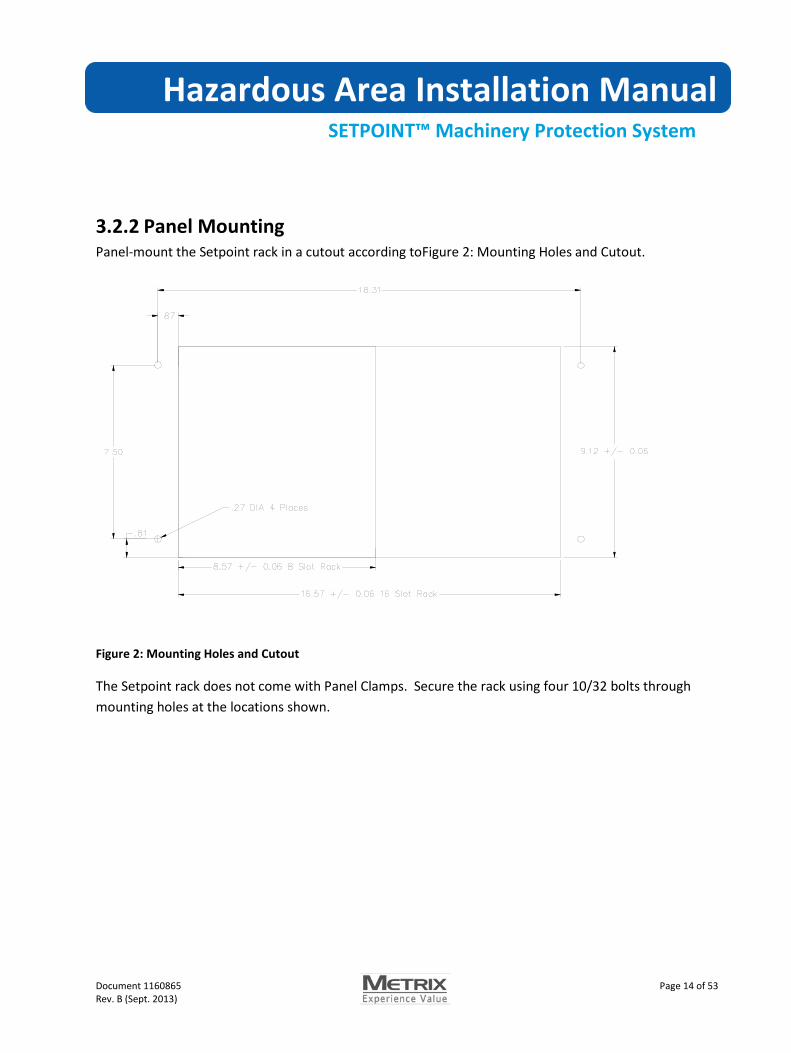
3.2.2 Panel Mounting Panel-mount the Setpoint rack in a cutout according toFigure 2: Mounting Holes and Cutout.
Figure 2: Mounting Holes and Cutout
The Setpoint rack does not come with Panel Clamps. Secure the rack using four 10/32 bolts through mounting holes at the locations shown.

Hazardous Area Installation Manual
SETPOINT™ Machinery Protection System
Document 1160865 Page 15 of 53 Rev. B (Sept. 2013)
3.2.3 Bulkhead Mounting To bulkhead mount a Setpoint rack, the mounting brackets are installed on the backside of the rack as shown.
Figure 3: Bulkhead Mounting
The mounting hole pattern for bulkhead mounting is the same as for panel mounting. Refer to Figure 2.
3.2.4 Box Mounting The Setpoint system’s small, front-loading design lends itself well to mounting in weatherproof or explosion proof boxes. Be sure to consider heat dissipation to ensure the box interior stays within the Setpoint ambient temperature rating. If possible, keep the box out of direct sunlight. Refer to the module datasheets for power dissipation information in order to calculate heat rise inside the box. Provide ventilation air if required.
3.2.5 Mounting the Display Remotely You can mount the Setpoint door and display up to 3 meters (10 feet) from the Setpoint rack using the remote display option. Anchor the display cable to a solid surface every 15 cm (6 inches). Refer
Bulkhead Mount Brackets

Hazardous Area Installation Manual
SETPOINT™ Machinery Protection System
Document 1160865 Page 16 of 53 Rev. B (Sept. 2013)
to the remote display datasheet for part numbers and ordering information.Refer to datasheet 1110470 for additional details on MX2020/RDP Remote Display Panel.
3.2.6 Reverse Mounting For applications requiring the system wiring to terminate at the rack back, you can move the display to the rack back and install in panels or 19 inch EIA racks following the instructions in 3.2.1 or 3.2.2. Reverse mounting requires a longer display cable to reach from the System Access Module to the display. Refer to the datasheet for display cable part numbers and ordering information.
Figure 4: Reverse Mounting the Rack
Modules now insert from the rack back with sensor and relay wiring terminating on the back.
Use a longer display cable to connect the display to the SAM display connector on the rack back.
Move the display brackets from the front to the back.
Hazardous Area Installation Manual
SETPOINT™ Machinery Protection System
Document 1160865 Page 17 of 53 Rev. B (Sept. 2013)
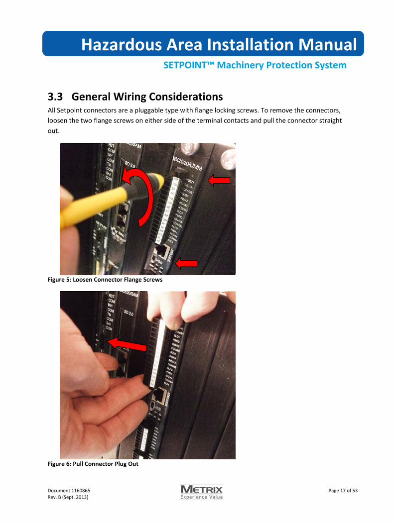
3.3 General Wiring Considerations All Setpoint connectors are a pluggable type with flange locking screws. To remove the connectors, loosen the two flange screws on either side of the terminal contacts and pull the connector straight out.
Figure 5: Loosen Connector Flange Screws
Figure 6: Pull Connector Plug Out

Hazardous Area Installation Manual
SETPOINT™ Machinery Protection System
Document 1160865 Page 18 of 53 Rev. B (Sept. 2013)
Strip wires to 6.5 mm (0.25 in).
6.5 mm (.25 in)
Fully open the connector by turning the terminal screw counterclockwise.
Insert the wire and tighten the connector by turning the screw clockwise. Torque to 0.2 Nm.

Hazardous Area Installation Manual
SETPOINT™ Machinery Protection System
Document 1160865 Page 19 of 53 Rev. B (Sept. 2013)
3.4 Rack Connection ModuleConnections The Rack Connection Module (RCM) installs in the Setpoint rack slot 1 (left).
The RCM provides connections for:
• System Chassis Ground • Single Point System Common to Chassis Ground • +24 V System Primary Power • +24 V System Secondary Power • Fault Relay • Discrete Control Contacts • Buffered Outputs
3.4.1 System Chassis Ground Connect chassis ground wire to the rack at the RCM power connector chassis terminal. Follow electrical codes when selecting wire size, maximum wire length, and maximum earth ground resistance. When used in Zone 2 hazardous area applications, use a 4 mm2 wire with crimp style lug to connect the chassis ground wire to earth ground.
The external power supplies are powered from high voltages. Only qualified personnel should make connections to the power supply. Refer to instructions included with the power supply module.

Hazardous Area Installation Manual
SETPOINT™ Machinery Protection System
Document 1160865 Page 20 of 53 Rev. B (Sept. 2013)
3.4.2 Single Point System Common to Chassis Connection For normal installation, insert the jumper between COM and as shown. This connects the internal system ground to the chassis. You can install the jumper at either the Power 1 or Power 2 plugs. Both work the same.
Figure 7: Chassis Jumper Installation
When usingZener safety barriers, or when the internal system ground is connected to another instrument ground, remove the jumper.
Figure 8: Chassis Jumper Removal
Jumper Installed
Loosen screws and remove jumper

Hazardous Area Installation Manual
SETPOINT™ Machinery Protection System
Document 1160865 Page 21 of 53 Rev. B (Sept. 2013)
3.4.3 Power Wiring Select the power wiring gauge to be large enough to keep the input supply voltage within the normal range of +22 Vdc to +30 Vdc. The amount of cable resistance allowed is determined by the maximum Setpoint rack current draw and the nominal power supply.
Table 1 shows the maximum wire length for fully loaded racks when powered with a +24 Vdc power supply.
Table 1: Maximum Power Wire Length at +24 Vdc Input Power
Wire Size 16 slot rack 8 slot rack 4 slot rack
12 AWG 23 m (75 ft.) 61 m (200 ft.) 104 m (340 ft.)
14 AWG 18 m (50 ft.) 46 m (150 ft.) 76 m (250 ft.)
16 AWG 9 m (30 ft.) 24 m (80 ft.) 41 m (135 ft.)
18 AWG 6 m (20 ft.) 16 m (50 ft.) 26 m (85 ft.)
20 AWG 4 m (12 ft.) 9 m (30 ft.) 15 m (49 ft.)
22 AWG 2.5 m (8 ft.) 6.5 m (21 ft.) 11 m (36 ft.)

Hazardous Area Installation Manual
SETPOINT™ Machinery Protection System
Document 1160865 Page 22 of 53 Rev. B (Sept. 2013)
3.4.4 Fault Relay Wiring The Setpoint fault relay is a fault tolerant Single-Pole, Double-Throw (form C) relay. The fault relay activates whenever machine protection is compromised due to a detected failure.
The fault relay labeling is in reference to the fault condition (i.e. when a fault occurs NC will be connected to ARM.). The fault relay is normally energized when the system is operating correctly and de-energizes to indicate a fault condition. Loss of rack power causes a fault indication.
Connect to the fault relay using AWG 12 to 24 AWG wire (0.2 mm2 to 4 mm2). Refer to the specifications for the fault relay current and voltage rating shown in the datasheet.
NC
ARM
NO
NC
NO
ARM
System Unpowered or Fault
NC
NO
ARM
No Fault
Figure 9: Fault Relay Operation
Electrical Shock Hazard: High voltages may be present on relay wiring. Remove power before servicing relay connections.

Hazardous Area Installation Manual
SETPOINT™ Machinery Protection System
Document 1160865 Page 23 of 53 Rev. B (Sept. 2013)
3.4.5 Discrete Control Input Wiring The discrete input connector provides control signal inputs from external devices, dry contact relays, or switches. All discrete inputs are active low and are asserted when the input is pulled to common. The discrete inputs are 5V logic compatible and can be pulled low by logic gates.
Figure 10: Discrete Contact Inputs
Connect to the discrete inputs using AWG 14 to AWG 28 wire as shown below.
Caution! Connecting high voltage wetted relays to the discrete contacts can damage the module. Connect only dry contact relays or low voltage logic.

Hazardous Area Installation Manual
SETPOINT™ Machinery Protection System
Document 1160865 Page 24 of 53 Rev. B (Sept. 2013)
3.4.6 Digital Inputs The Setpoint UMM supports discrete digital inputs from external +3.3 V logic devices, +5V logic devices, or from a dry contact relay closure. Figure 11 shows how to wire logic devices and dry contact relays to the UMM inputs. Table 2 shows the Measurement value for the supported input states.
Figure 11: Wiring Digital Inputs
Table 2: Digital Input Operation
Input Source Level Measurement Value
+3.3 V or +5 V Logic Device 0 V to +1 V 0%
+3.3 V or +5 V Logic Device > 2 V 100%
Relay Relay Closed 0%
Relay Relay Opened 100%
MX2020/UMM
PWR1SIG/A1COM/B1SLD1PWR2SIG/A2COM/B2SLD2PWR3SIG/A3COM/B3SLD3PWR4SIG/A4COM/B4SLD4Connect relay armature to UMM COM
input and either relay NC or NO contacts to the UMM SIG input.
Connect logic device outputs to the UMM SIG input. Connect UMM COM input to the logic device common.
Hazardous Area Installation Manual
SETPOINT™ Machinery Protection System
Document 1160865 Page 25 of 53 Rev. B (Sept. 2013)
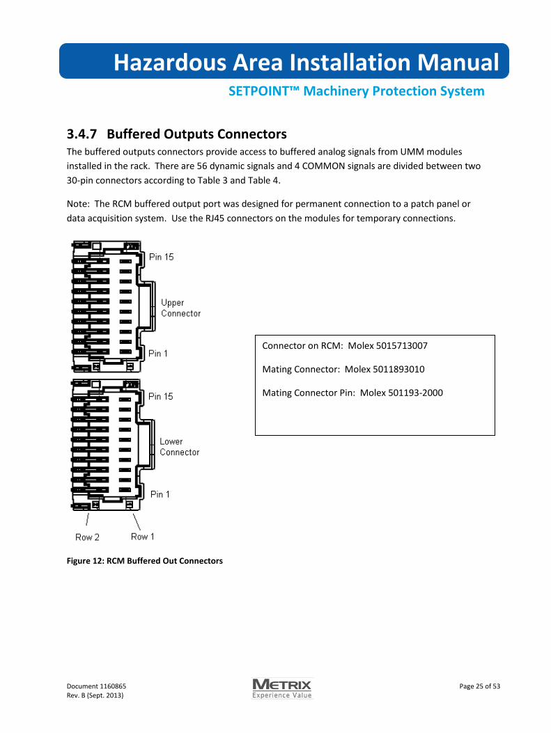
3.4.7 Buffered Outputs Connectors The buffered outputs connectors provide access to buffered analog signals from UMM modules installed in the rack. There are 56 dynamic signals and 4 COMMON signals are divided between two 30-pin connectors according to Table 3 and Table 4.
Note: The RCM buffered output port was designed for permanent connection to a patch panel or data acquisition system. Use the RJ45 connectors on the modules for temporary connections.
Figure 12: RCM Buffered Out Connectors
Connector on RCM: Molex 5015713007
Mating Connector: Molex 5011893010
Mating Connector Pin: Molex 501193-2000
Hazardous Area Installation Manual
SETPOINT™ Machinery Protection System
Document 1160865 Page 26 of 53 Rev. B (Sept. 2013)
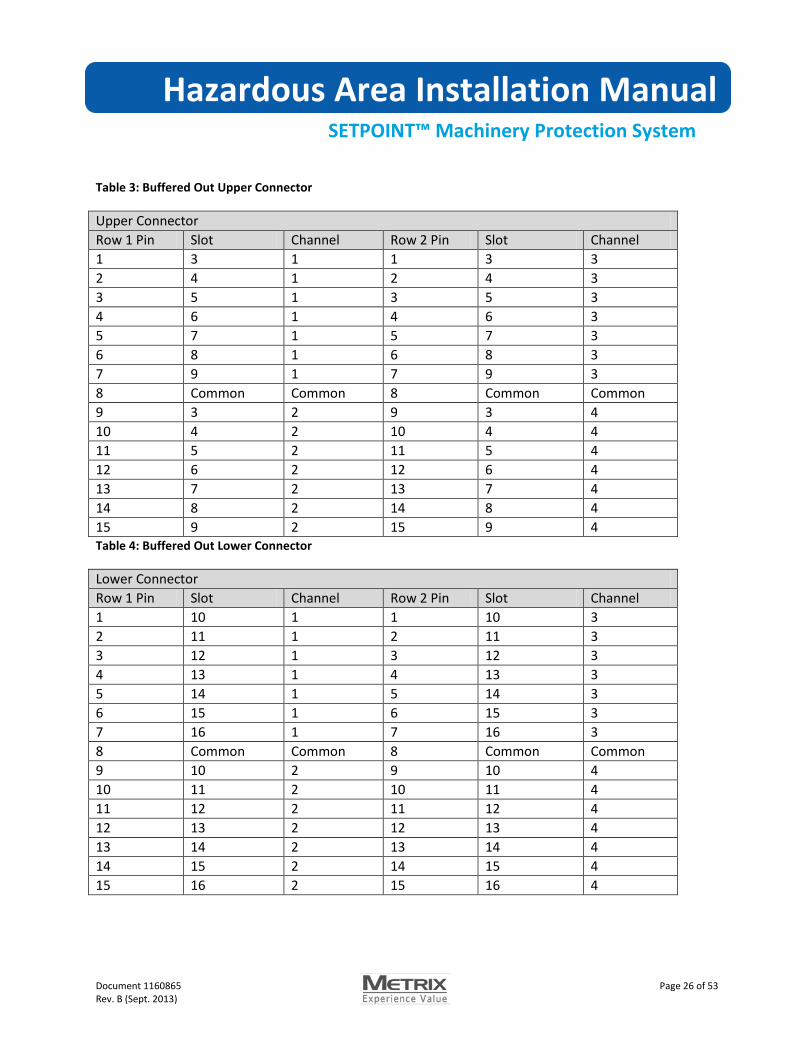
Table 3: Buffered Out Upper Connector
Upper Connector Row 1 Pin Slot Channel Row 2 Pin Slot Channel 1 3 1 1 3 3 2 4 1 2 4 3 3 5 1 3 5 3 4 6 1 4 6 3 5 7 1 5 7 3 6 8 1 6 8 3 7 9 1 7 9 3 8 Common Common 8 Common Common 9 3 2 9 3 4 10 4 2 10 4 4 11 5 2 11 5 4 12 6 2 12 6 4 13 7 2 13 7 4 14 8 2 14 8 4 15 9 2 15 9 4 Table 4: Buffered Out Lower Connector
Lower Connector Row 1 Pin Slot Channel Row 2 Pin Slot Channel 1 10 1 1 10 3 2 11 1 2 11 3 3 12 1 3 12 3 4 13 1 4 13 3 5 14 1 5 14 3 6 15 1 6 15 3 7 16 1 7 16 3 8 Common Common 8 Common Common 9 10 2 9 10 4 10 11 2 10 11 4 11 12 2 11 12 4 12 13 2 12 13 4 13 14 2 13 14 4 14 15 2 14 15 4 15 16 2 15 16 4

Hazardous Area Installation Manual
SETPOINT™ Machinery Protection System
Document 1160865 Page 27 of 53 Rev. B (Sept. 2013)
3.4.8 Switchable BNC connectors: Setpoint Racks purchased with the display option provide three switchable BNC connectors. Switchable BNC connectors allow you to quickly change the buffered out signals into a portable data collector or other test equipment without connecting or reconnecting BNC cables.
3.5 System Access Module Connections The System Access Module (SAM) installs in the Setpoint rack slot 2. Future Setpoint functionality will allow installation of a redundant SAM in rack slot 3.
The SAM provides connections for:
• SD Card Data Storage • Ethernet Modbus/TCP connection to the controller • Ethernet Data Acquisition computer connection • Display connection
3.5.1 SD Card Installation The Dynamic Data option (future) is required to activate the SD card functionality. The SD card iscurrently used for Display Module program updates.

Hazardous Area Installation Manual
SETPOINT™ Machinery Protection System
Document 1160865 Page 28 of 53 Rev. B (Sept. 2013)
3.5.2 Modbus/TCP Ethernet Connection The top port provides static data and statuses to a control system via 10/100baseT Ethernet using a standard CAT5 or CAT6 cable with an RJ45 connector.
The maximum length for twisted pair wiring without an interposing switch or hub is 100 m (328 ft).
Note: Ethernet connection to the Setpoint Setup softwareis not currently available.
Client 2
Figure 13: Connecting to Modbus
Modbus Client 1
M
odbu
s Clie
nts
Switc
h
Modbus
Modbus Client 3
Modbus Client 4
Modbus Client 5
Modbus Client 6
Master Clock
SETPOINT Config SW

Hazardous Area Installation Manual
SETPOINT™ Machinery Protection System
Document 1160865 Page 29 of 53 Rev. B (Sept. 2013)
3.5.3 Ethernet Data Acquisition Computer (DAC) Connection The lower Ethernet port provides dynamic data to a data acquisition computer (future) via 10/100/1000base T Ethernet. When connecting to a 1000baseT (gigabit) Ethernet network, use CAT6 cable. Slower networks can use CAT5 or CAT6 cable. The connector is a standard RJ45.
Hazardous Area Installation Manual
SETPOINT™ Machinery Protection System
Document 1160865 Page 30 of 53 Rev. B (Sept. 2013)
3.6 Monitor Module Connections This section describes installation of the UMM and TMM monitor modules including:
• Relay Wiring • Analog 4 to 20 mA output wiring • UMM sensor wiring • TMM sensor wiring
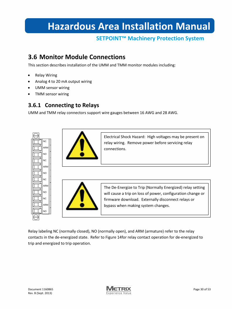
3.6.1 Connecting to Relays UMM and TMM relay connectors support wire gauges between 16 AWG and 28 AWG.
NC
ARM
NO
NC
ARM
NO
NC
ARM
NO
NC
ARM
NO
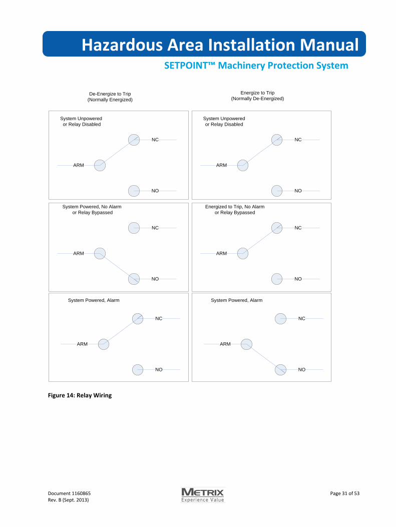
Relay labeling NC (normally closed), NO (normally open), and ARM (armature) refer to the relay contacts in the de-energized state. Refer to Figure 14for relay contact operation for de-energized to trip and energized to trip operation.
Electrical Shock Hazard: High voltages may be present on relay wiring. Remove power before servicing relay connections.
The De-Energize to Trip (Normally Energized) relay setting will cause a trip on loss of power, configuration change or firmware download. Externally disconnect relays or bypass when making system changes.
Hazardous Area Installation Manual
SETPOINT™ Machinery Protection System
Document 1160865 Page 31 of 53 Rev. B (Sept. 2013)
NC
NO
ARM
System Unpowered or Relay Disabled
NC
NO
ARM
System Powered, No Alarm or Relay Bypassed
NC
NO
ARM
System Powered, Alarm
NC
NO
ARM
System Unpowered or Relay Disabled
NC
NO
ARM
Energized to Trip, No Alarmor Relay Bypassed
NC
NO
ARM
System Powered, Alarm
De-Energize to Trip(Normally Energized)
Energize to Trip(Normally De-Energized)
Figure 14: Relay Wiring

Hazardous Area Installation Manual
SETPOINT™ Machinery Protection System
Document 1160865 Page 32 of 53 Rev. B (Sept. 2013)
3.6.1.1 Connecting the Analog Outputs The monitor modules provide 4 to 20 mA outputs proportional to the Direct variable measurement. 4 mA corresponds to the configured bottom-scale, 20 mA corresponds to the configured full-scale. The 4 to 20 mA is self-powered (sourcing) and requires no external power source.
Shielded wire is recommended to reduce electrical noise. Terminate shielding at the receiving device.
In the event of a sensor fault, the 4 to 20 mA output will drop to 2 mA or to a programmed clamp value depending on configuration. An output between 20 mA and 24 mA indicates an over-range condition.
3.6.2 Universal Monitoring Module (UMM) Sensor Wiring This section describes installation of the Universal Monitoring Module including field wiring for:
-24 V, 2-wire Proximity Transducers (MX2030) -24 V, 3-wire Proximity Transducers -24 V, 3-wire Acceleration Transducers +24 V, 2-wire IEPE Accelerometers +24 V, 2-wire IEPE Velocity Sensors Moving coil velocity sensors -24 V, 3-wire Proximity type speed sensors 2-wire loop powered process variable transmitters Externally powered process variable transmitters

Hazardous Area Installation Manual
SETPOINT™ Machinery Protection System
Document 1160865 Page 33 of 53 Rev. B (Sept. 2013)
3.6.2.1 Wiring Metrix Two-Wire Proximity Sensors Connect the Metrix Setpoint MX2030 sensor power to the UMM PWR terminal and the MX2030 signal line to the UMM Sig/A input.
Note: Due to compliance voltage requirements across the Setpoint MX2030 sensor, the scale factor measured at the UMM Sig/A input is 50 mV/mil. The UMM provides gain to convert this signal to 200 mV/mil at the buffered outputs.
Figure 15: MX2030 Wiring

Hazardous Area Installation Manual
SETPOINT™ Machinery Protection System
Document 1160865 Page 34 of 53 Rev. B (Sept. 2013)
3.6.2.2 Wiring 3-Wire Proximity Transducers Connect standard, -24 V powered Proximity transducers as shown below:
Figure 16: -24 V Proximity Sensor Wiring

Hazardous Area Installation Manual
SETPOINT™ Machinery Protection System
Document 1160865 Page 35 of 53 Rev. B (Sept. 2013)
3.6.2.3 Wiring 3-Wire Accelerometers Connect 3-wire, voltage mode accelerometers as shown below:
Figure 17: -24 V, 3-wire Accelerometer wiring

Hazardous Area Installation Manual
SETPOINT™ Machinery Protection System
Document 1160865 Page 36 of 53 Rev. B (Sept. 2013)
3.6.2.4 Wiring IEPE Transducers The UMM provides +24Vdc at 3 mA constant current to power typical IEPE 2-wire sensors. Connect the transducer “A” wire to the UMM Sig/A wire and the transducer “B” wire to the UMM COM/B terminal as shown in Figure 18: IEPE Transducer Wiring.
Figure 18: IEPE Transducer Wiring
Note: Sensors designed for negative voltage operation, such as the Bently Nevada Velomitor, typically have the A terminal connected to COM and the B terminal connected to a -24V constant current source. These sensors can be wired to +24 constant current using the same wiring as for positive voltage sensors shown above, however the sensor noise shielding may be impaired.
Hazardous Area Installation Manual
SETPOINT™ Machinery Protection System
Document 1160865 Page 37 of 53 Rev. B (Sept. 2013)
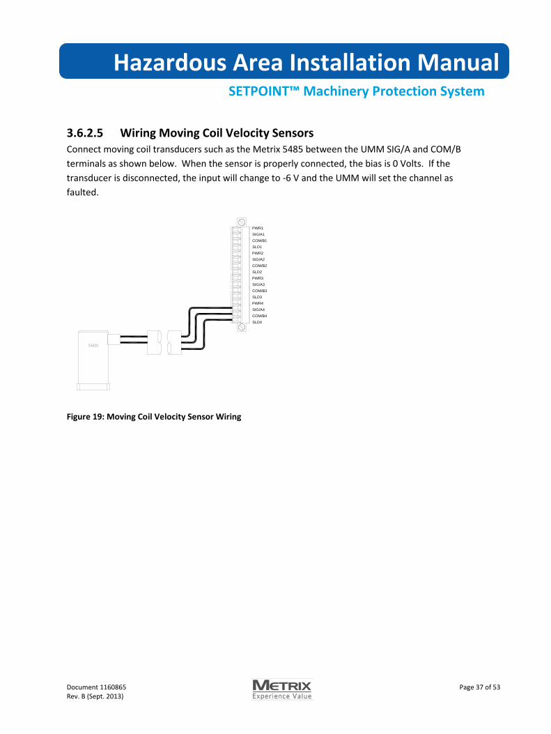
3.6.2.5 Wiring Moving Coil Velocity Sensors Connect moving coil transducers such as the Metrix 5485 between the UMM SIG/A and COM/B terminals as shown below. When the sensor is properly connected, the bias is 0 Volts. If the transducer is disconnected, the input will change to -6 V and the UMM will set the channel as faulted.
PWR1SIG/A1COM/B1SLD1PWR2SIG/A2COM/B2SLD2PWR3SIG/A3COM/B3SLD3PWR4SIG/A4COM/B4SLD4
Figure 19: Moving Coil Velocity Sensor Wiring
Hazardous Area Installation Manual
SETPOINT™ Machinery Protection System
Document 1160865 Page 38 of 53 Rev. B (Sept. 2013)
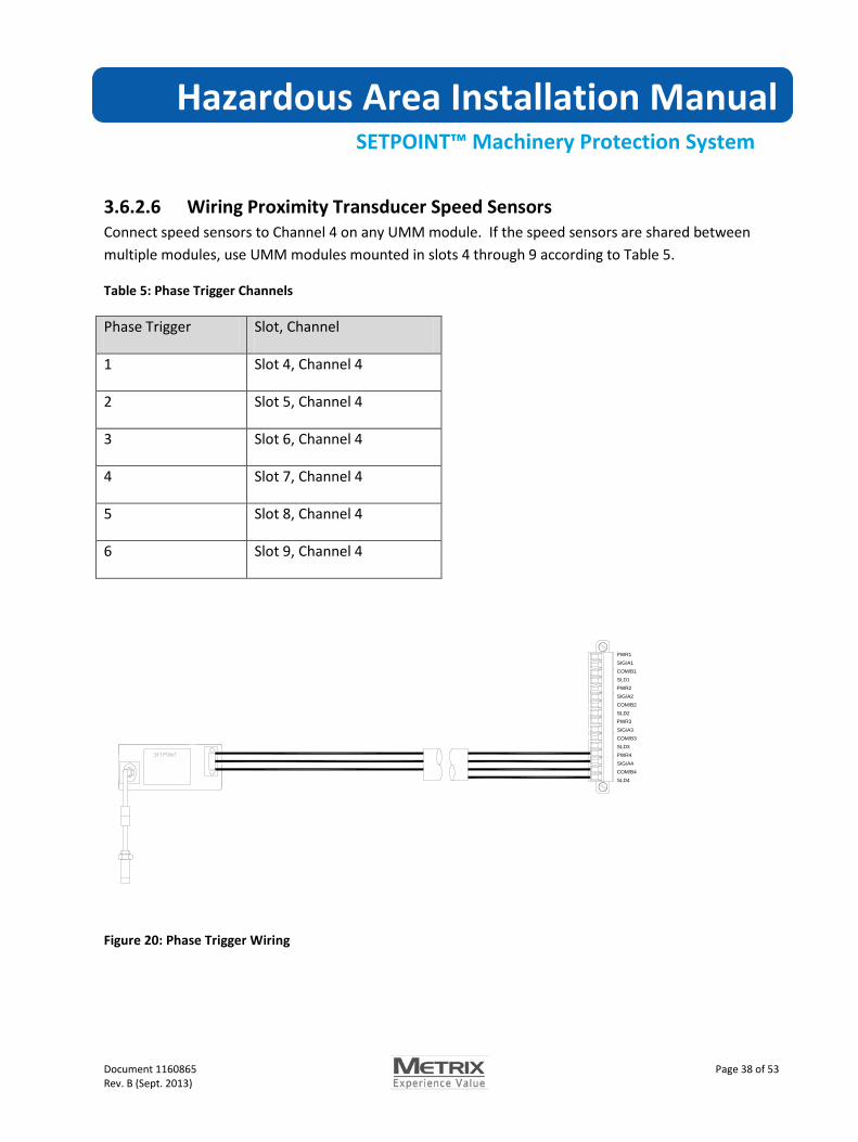
3.6.2.6 Wiring Proximity Transducer Speed Sensors Connect speed sensors to Channel 4 on any UMM module. If the speed sensors are shared between multiple modules, use UMM modules mounted in slots 4 through 9 according to Table 5.
Table 5: Phase Trigger Channels
Phase Trigger Slot, Channel
1 Slot 4, Channel 4
2 Slot 5, Channel 4
3 Slot 6, Channel 4
4 Slot 7, Channel 4
5 Slot 8, Channel 4
6 Slot 9, Channel 4
PWR1SIG/A1COM/B1SLD1PWR2SIG/A2COM/B2SLD2PWR3SIG/A3COM/B3SLD3PWR4SIG/A4COM/B4SLD4
Figure 20: Phase Trigger Wiring
Hazardous Area Installation Manual
SETPOINT™ Machinery Protection System
Document 1160865 Page 39 of 53 Rev. B (Sept. 2013)
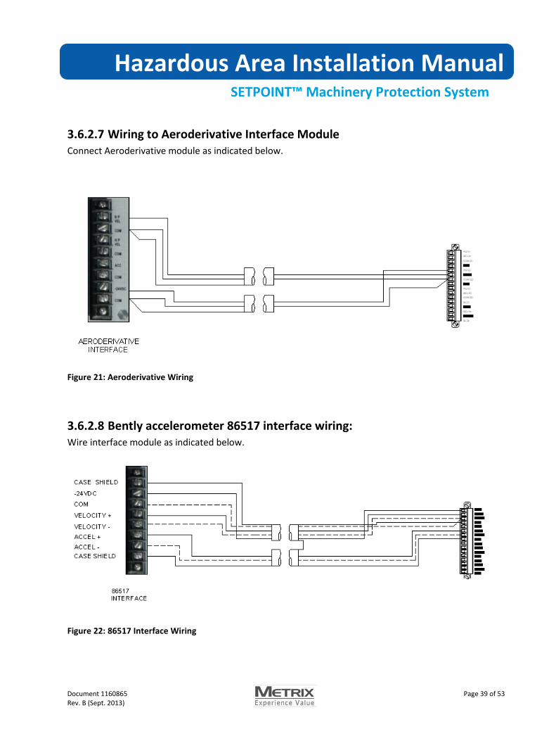
3.6.2.7 Wiring to Aeroderivative Interface Module Connect Aeroderivative module as indicated below.
Figure 21: Aeroderivative Wiring
3.6.2.8 Bently accelerometer 86517 interface wiring: Wire interface module as indicated below.
Figure 22: 86517 Interface Wiring
Hazardous Area Installation Manual
SETPOINT™ Machinery Protection System
Document 1160865 Page 40 of 53 Rev. B (Sept. 2013)
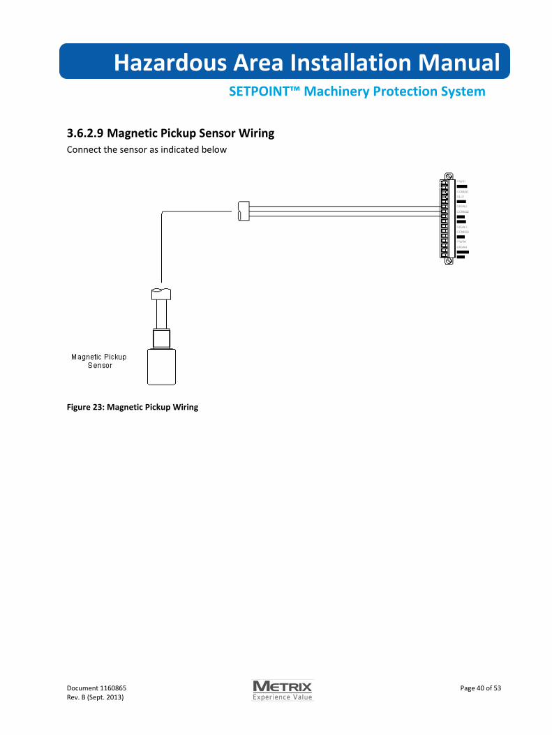
3.6.2.9 Magnetic Pickup Sensor Wiring Connect the sensor as indicated below
Figure 23: Magnetic Pickup Wiring

Hazardous Area Installation Manual
SETPOINT™ Machinery Protection System
Document 1160865 Page 41 of 53 Rev. B (Sept. 2013)
3.6.2.10 Wiring 4 to 20 mA Transmitters You can use the UMM to monitor 4 to 20 mA transmitter inputs. The UMM provides higher sampling rates, faster alarming, and buffered outputs not provided by the TMM.
3.6.2.10.1 Two-wire, Loop-Powered Transmitters Connect 4 to 20 mA 2-wire, loop-powered transmitters as shown in Figure . The UMM provides -24Vdc power sufficient to power the transmitter. The 4 to 20 mA current signal passes through a 249 ohm sense resistor to create a -1.0 V to -5.0 V analog signal that is inverted and gained to create a -1 V to -20 Vsignal available at the UMM buffered outputs.
1. Figure 23: UMM two wire Transmitter Wiring
Connect Loop- to PWR and Loop+ to SIG. Connect the transmitter shield to SLD.
Hazardous Area Installation Manual
SETPOINT™ Machinery Protection System
Document 1160865 Page 42 of 53 Rev. B (Sept. 2013)
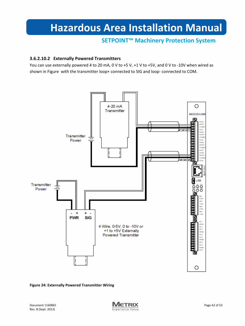
3.6.2.10.2 Externally Powered Transmitters You can use externally powered 4 to 20 mA, 0 V to +5 V, +1 V to +5V, and 0 V to -10V when wired as shown in Figure with the transmitter loop+ connected to SIG and loop- connected to COM.
Figure 24: Externally Powered Transmitter Wiring

Hazardous Area Installation Manual
SETPOINT™ Machinery Protection System
Document 1160865 Page 43 of 53 Rev. B (Sept. 2013)
3.6.2.11 Wiring the IT6810 Impact Transmitter The UMM supports impact measurements similar to the IT6810 Impact Transmitter. Using the UMM provides additional features such as buffered outputs, Modbus output, and alarming not available on the transmitter. You can reuse existing IT6810 Impact Transmitters with the UMM following the wiring described in this section.
Figure 24: Impact transmitter wiring
Wire the IT6810 with the A terminal connected to the -24V PWR output from the UMM and the B terminal connected to Sig. When wired with reverse polarity (A = -24V, B = 0) the IT6810 enters adjustment mode. In this mode, the IT6810 outputs the dynamic signal along with a periodic pulse at the window period. The amplitude of this pulse is equal to the IT6810 threshold setting. The UMM will count this pulse resulting in a reading of “1” each window. You can use this count to verify that the transducer is working and increase your alarm limits by 1. If this is not desirable, adjust the IT6810 threshold to minimum so the UMM will not count this pulse. Refer to the IT6810 Manual for instructions on lowering the threshold.
PWR SIG
Hazardous Area Installation Manual
SETPOINT™ Machinery Protection System
Document 1160865 Page 44 of 53 Rev. B (Sept. 2013)
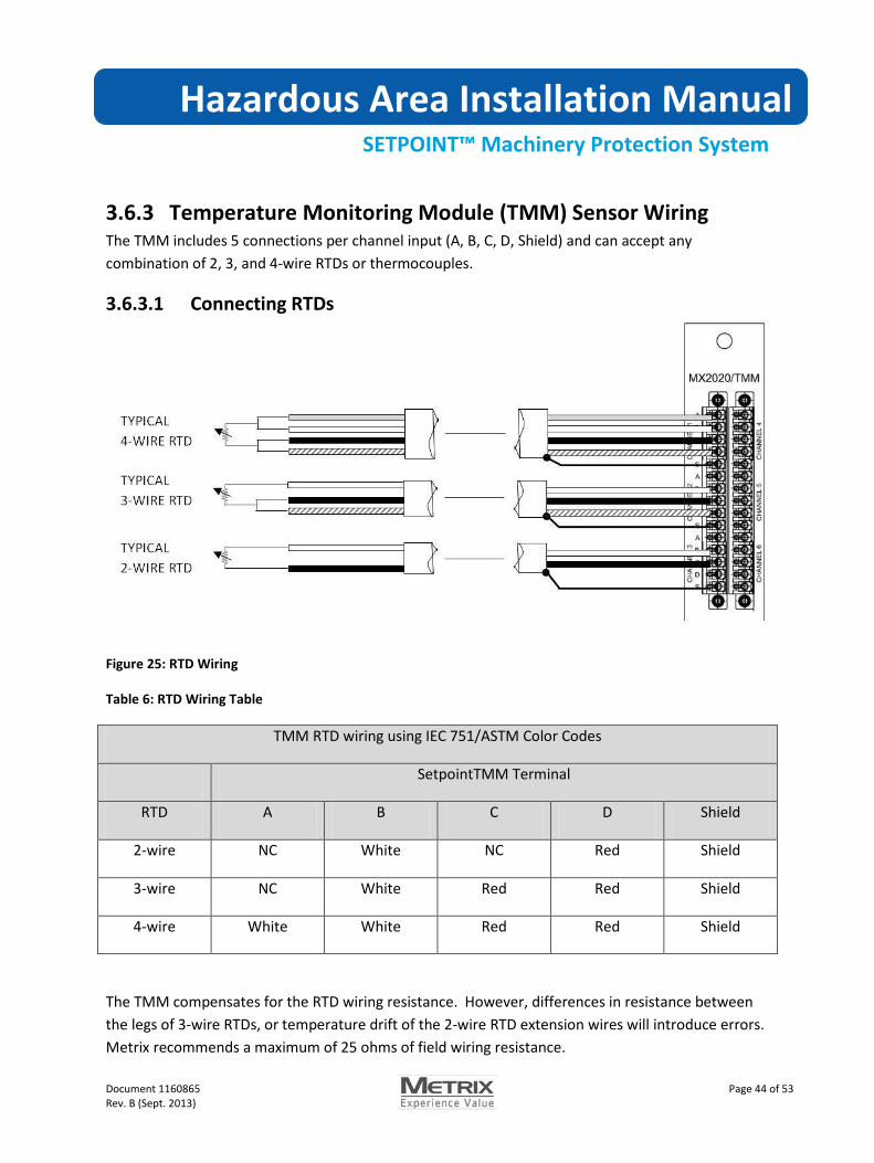
3.6.3 Temperature Monitoring Module (TMM) Sensor Wiring The TMM includes 5 connections per channel input (A, B, C, D, Shield) and can accept any combination of 2, 3, and 4-wire RTDs or thermocouples.
3.6.3.1 Connecting RTDs
Figure 25: RTD Wiring
Table 6: RTD Wiring Table
TMM RTD wiring using IEC 751/ASTM Color Codes
SetpointTMM Terminal
RTD A B C D Shield
2-wire NC White NC Red Shield
3-wire NC White Red Red Shield
4-wire White White Red Red Shield
The TMM compensates for the RTD wiring resistance. However, differences in resistance between the legs of 3-wire RTDs, or temperature drift of the 2-wire RTD extension wires will introduce errors. Metrix recommends a maximum of 25 ohms of field wiring resistance.

Hazardous Area Installation Manual
SETPOINT™ Machinery Protection System
Document 1160865 Page 45 of 53 Rev. B (Sept. 2013)
3.6.3.2 Connecting Thermocouples Thermocouple common lines are electrically isolated from the Setpoint system allowing connection to grounded tip thermocouples on a machine at ground potential different from the Setpointsystem. All thermocouple inputs are on the same common plane so grounded tip thermocouples should be at the same ground potential.
Figure 26: Thermocouple Wiring
Table 7 - Thermocouple Color Coding
ANSI/ASTM E-230 Color Coding IEC 584-3 Color Coding
B Terminal (+) C Terminal (-) B Terminal (+) C Terminal (-)
J White Red Black White
K Yellow Red Green White
T Blue Red Brown White
E Violet Red Violet White
Hazardous Area Installation Manual
SETPOINT™ Machinery Protection System
Document 1160865 Page 46 of 53 Rev. B (Sept. 2013)
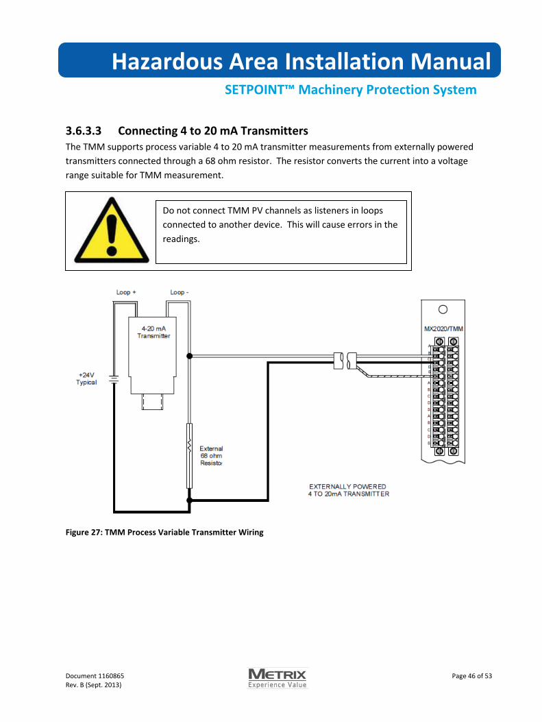
3.6.3.3 Connecting 4 to 20 mA Transmitters The TMM supports process variable 4 to 20 mA transmitter measurements from externally powered transmitters connected through a 68 ohm resistor. The resistor converts the current into a voltage range suitable for TMM measurement.
Figure 27: TMM Process Variable Transmitter Wiring
Do not connect TMM PV channels as listeners in loops connected to another device. This will cause errors in the readings.

Hazardous Area Installation Manual
SETPOINT™ Machinery Protection System
Document 1160865 Page 47 of 53 Rev. B (Sept. 2013)
4 Standards
4.1.1 Standards for Zones IECEx ATEX Canada (Zones) United States (Zones) IEC 60079-0:2007 Ed 5
IEC 60079-11:2006 Ed 5.1
IEC 60079-15:2009 Ed 4
EN 60079-0:2006
EN 60079-11:2007
EN 60079-15:2010
CAN/CSA 60079-0:2006
CAN/CSA 60079-11:2007
CAN/CSA 60079-15:2005
ANSI/UL 60079-0:2006
ANSI/UL 60079-11:2007
ANSI/UL 60079-15:2005
(The requirements of the equivalent ATEX, IECEx and CAN/CSA and UL standards are similar; therefore, any references in the following report can be regarded as referring to either format unless stated otherwise.)
4.1.2 Standards for Divisions Canada (Divisions) United States (Divisions) C22.2 No 157 – 92, Intrinsically Safe and Non-Incendive Equipment for Use in Hazardous Locations.
C22.2 No 213 – M1987, Non-Incendive Electrical Equipment for Use in Class I, Division 2 Hazardous Locations.
UL 913, Sixth Edition Intrinsically Safe Apparatus and Associated Apparatus for use in Class I, II, III, Division 1, Hazardous (Classified) Locations.
UL 1604, Third Edition, Electrical Equipment for Use in Class I and II, Division 2, And Class III Hazardous (Classified) Locations.

Hazardous Area Installation Manual
SETPOINT™ Machinery Protection System
Document 1160865 Page 48 of 53 Rev. B (Sept. 2013)
5 Maintenance This section describes typical procedures for performing Setpoint system maintenance including:
• Inserting an Removing Modules
• Upgrading Firmware
5.1 Inserting and Removing Modules Follow the procedures below when adding, removing, or replacing Setpoint Modules. You may remove Setpoint Modules while the system is powered (Hot Swap). While hot swapping modules does not damage modules, removing and inserting modules into a live system will cause the module statuses to become invalid and the Fault relay to activate. Depending on the voting logic, this can cause an alarm relay trip.
Modules inserted into a live rack will begin protection functions as soon as the module boots up and the filters settle. When hot inserting modules into a rack make sure the module configuration is correct before insertion or else inhibit rack alarming until the module is correctly configured.
Setpoint Modules can be damaged by electrostatic shock when removed from the rack. Take appropriate precautions such as grounding straps when removing or handling Setpoint modules.
Modules removed from the system cause loss of machine protection. Depending on relay voting logic, loss of protection can cause relays to activate. Bypass relays before removing modules
Removing and inserting cables and modules can cause sparking that can ignite hazardous gases. Verify the area is safe before performing maintenance.

Hazardous Area Installation Manual
SETPOINT™ Machinery Protection System
Document 1160865 Page 49 of 53 Rev. B (Sept. 2013)
To remove a module:
1) If necessary, remove field wiring connectors (refer to section 3.3. 2) Fully loosen the two captive screws located at the top and bottom of the module. The
captive screws are spring-loaded and will spring out when fully disengaged.
Figure 28: Loosen Captive Screws
3) Grasp the captive screw large knurled knobs and pull the module from the rack.
Figure 29: Removing a Module

Hazardous Area Installation Manual
SETPOINT™ Machinery Protection System
Document 1160865 Page 50 of 53 Rev. B (Sept. 2013)
To install a module:
1) Align the card edges with the card guide slots on the left. 2) Slowly push the card in until the connector alignment pins engage. 3) Firmly push the module to seat the connector pins. 4) Tighten the captive screws finger tight 5) Use a screwdriver to tighten an additional 1/8 turn.
Figure 30: Module Installation
Hazardous Area Installation Manual
SETPOINT™ Machinery Protection System
Document 1160865 Page 51 of 53 Rev. B (Sept. 2013)
5.2 Removing or Installing the Door Follow these steps to install or remove the rack front door.
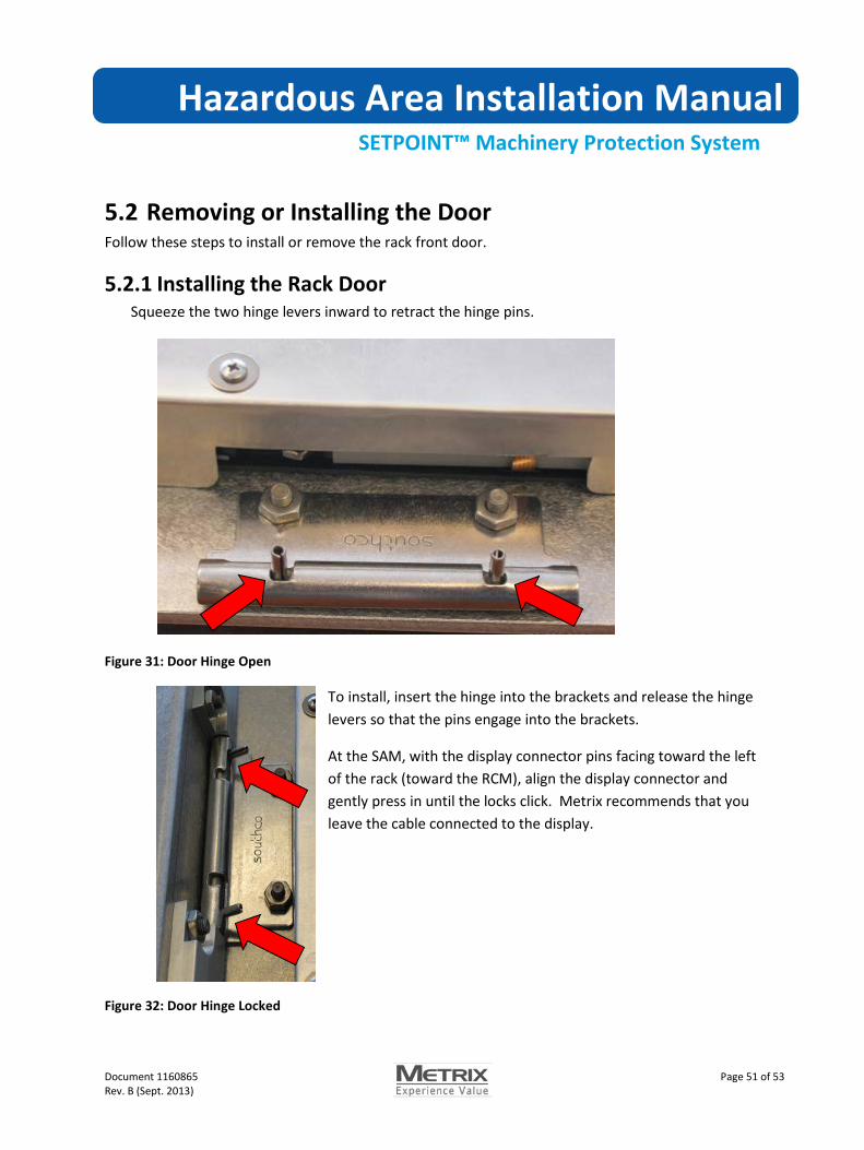
5.2.1 Installing the Rack Door Squeeze the two hinge levers inward to retract the hinge pins.
Figure 31: Door Hinge Open
To install, insert the hinge into the brackets and release the hinge levers so that the pins engage into the brackets.
At the SAM, with the display connector pins facing toward the left of the rack (toward the RCM), align the display connector and gently press in until the locks click. Metrix recommends that you leave the cable connected to the display.
Figure 32: Door Hinge Locked
Hazardous Area Installation Manual
SETPOINT™ Machinery Protection System
Document 1160865 Page 52 of 53 Rev. B (Sept. 2013)
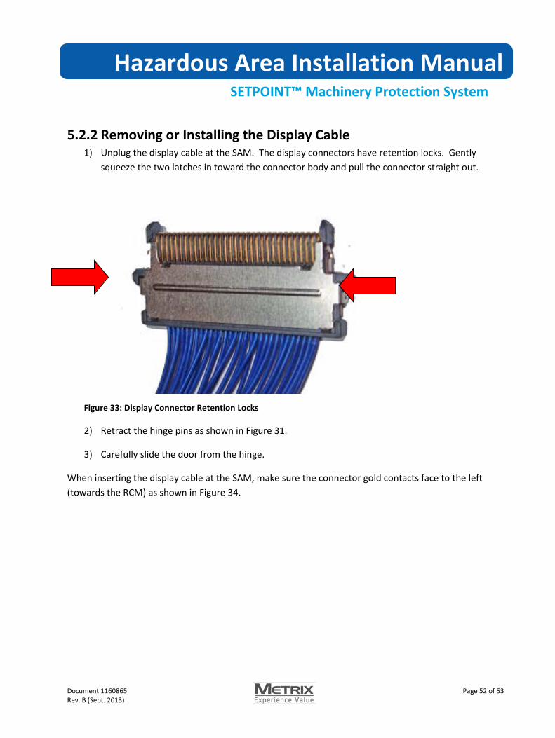
5.2.2 Removing or Installing the Display Cable 1) Unplug the display cable at the SAM. The display connectors have retention locks. Gently
squeeze the two latches in toward the connector body and pull the connector straight out.
Figure 33: Display Connector Retention Locks
2) Retract the hinge pins as shown in Figure 31.
3) Carefully slide the door from the hinge.
When inserting the display cable at the SAM, make sure the connector gold contacts face to the left (towards the RCM) as shown in Figure 34.

Hazardous Area Installation Manual
SETPOINT™ Machinery Protection System
Document 1160865 Page 53 of 53 Rev. B (Sept. 2013)
Figure 34: Inserting the Display Cable at the SAM
© Copyright 201X, Metrix Instrument Company, L.P. All rights reserved.
Revision History:
ECR Number Change Description Revision
NONE Initial Release A