hawk 8000 controller wifi guide - centraline · hawk 8000 controller – wifi guide 3 en2z-1029ge51...
TRANSCRIPT

HAWK 8000 Controller WiFi Guide
® U.S. Registered Trademark
Copyright © 2017 Honeywell Inc. • All Rights Reserved EN2Z-1029GE51 R0517
TABLE OF CONTENTS
About this Guide ----------------------------------------------------------------------------------------------------------------------------------------------- 2 Product Documentation ------------------------------------------------------------------------------------------------------------------------------- 2 Document Content ------------------------------------------------------------------------------------------------------------------------------------- 2
Overview ---------------------------------------------------------------------------------------------------------------------------------------------------------- 3 WiFi Specifications ------------------------------------------------------------------------------------------------------------------------------------- 3
Common Tasks ------------------------------------------------------------------------------------------------------------------------------------------------- 4 Configuring WiFi Access Point Mode ------------------------------------------------------------------------------------------------------------- 4 Configuring WiFi Client Mode ----------------------------------------------------------------------------------------------------------------------- 6 Switching WiFi Modes --------------------------------------------------------------------------------------------------------------------------------- 7 Adding a New Wireless Network ------------------------------------------------------------------------------------------------------------------- 7 Editing a Wireless Network -------------------------------------------------------------------------------------------------------------------------- 8 Restarting the WiFi Adapter after Inactivity Timeout Shutdown ---------------------------------------------------------------------------- 8
Reference ------------------------------------------------------------------------------------------------------------------------------------------------------- 10 Secure Storage and the microSD Flash Memory Card ------------------------------------------------------------------------------------- 10 WiFi Configuration Switch Details ---------------------------------------------------------------------------------------------------------------- 10 WiFi Configuration Switch Positions ------------------------------------------------------------------------------------------------------------- 11 WiFi Configuration View ---------------------------------------------------------------------------------------------------------------------------- 11 Client Mode Tab -------------------------------------------------------------------------------------------------------------------------------------- 14 Access Point Mode Tab ---------------------------------------------------------------------------------------------------------------------------- 16 Supported WiFi Configurations ------------------------------------------------------------------------------------------------------------------- 18
Glossary --------------------------------------------------------------------------------------------------------------------------------------------------------- 23
Related Technical Literature ----------------------------------------------------------------------------------------------------------------------------- 24
Trademark Information LON, LONWORKS, and Neuron are trademarks of Echelon Corporation registered in the United States and other countries.

HAWK 8000 CONTROLLER – WIFI GUIDE
EN2Z-1029GE51 R0517 2
ABOUT THIS GUIDE This topic contains important information about the purpose, content, context, and intended audience for this document.
Product Documentation Released versions of NX software include a complete collection of technical information that is provided in both online help and PDF format. The information in this document is written primarily for Systems Integrators. In order to make the most of the information in this book, readers should have some training or previous experience with NX or NiagaraAX software.
Document Content This document provides basic information about the HAWK 8000 WiFi option. Included are an overview, and descriptions of WiFi requirements, operation notes, and configuration instructions.
This guide is intended for developers, systems engineers, and facility managers.

HAWK 8000 CONTROLLER – WIFI GUIDE
EN2Z-1029GE51 R0517 3
OVERVIEW Topics covered in this chapter
♦ WiFi Specifications
The HAWK 8000 platform features an integrated IEEE 802.11 module for enabling wireless Ethernet communications to or from the platform. Both Client mode and Access Point mode are supported. However, the HAWK 8000 cannot perform in both modes simultaneously.
NOTE: Starting in NX 4.2, the HAWK 8000 can be converted (downgraded) to run AX 3.8.111.6.5 - with some feature limitations. For example, for any HAWK 8000 running AX, the WiFi functionality is not supported. In this configuration, the position of the WiFi Configuration Switch is not monitored. Other unsupported features are IEEE 802.1X wired authentication and USB backup/restore.
Disabled by default from the factory, you can also disable the WiFi feature either via the WiFi Configuration Switch on the housing or remotely via platform WiFi Configuration view. The initial WiFi setup requires COACH NX or serial connectivity. The process of enabling WiFi varies slightly depending on the country the HAWK 8000 is shipped to. When enabled, you can configure the HAWK 8000 as a client to an already established IEEE 802.11 access point and network, or as an access point to establish a new network.
The WiFi feature adds a new platform view, the WiFi Configuration view for HAWK 8000 platform (the only current Niagara NX platform supporting WiFi). In addition, the HAWK 8000 command line system console has a Configure WiFi option which you can use to initially configure WiFi, although this provides only a subset of the configuration parameters that are available via the platform view.
WiFi Specifications The WiFi option can be enabled and configured to attach as a Client (CLT) to an already established IEEE 802.11 access point and network, or configured as an Access Point (ACC) to establish a new network.
• Supports IEEE 802.11a/b/g/n networks • Configurable radio (OFF, ACC, CLT) • Supports WPA-PSK, WPA2-PSK security protocols
NOTE: The HAWK 8000 does not support enterprise-level authentication (such as WPA2-enterprise), WEP authentication, or using no authentication at all.
• Supports 2.4 or 5.8 GHz frequencies – 2.4 GHz channels: 1–11 – 5.8 GHz channels: 36, 40, 44, 48,149, 153, 157, 161, and 165.
NOTE: The following Dynamic Frequency Selection (DFS) channels in the 5 GHz range are not supported: 52, 56, 60, 64, 100, 104, 108, 112, 116, 132, 136, 140.
• Single dual band 2.4/5.8 GHz antenna. The antenna may be remotely located using an extension cable.

HAWK 8000 CONTROLLER – WIFI GUIDE
EN2Z-1029GE51 R0517 4
COMMON TASKS Topics covered in this chapter
♦ Configuring WiFi Access Point mode
♦ Configuring WiFi Client mode
♦ Switching WiFi modes
♦ Adding a new wireless network
♦ Editing a wireless network
♦ Restarting the WiFi adapter after Inactivity Timeout shutdown
The following procedures describe how to configure the HAWK 8000 WiFi adapter for Access Point mode or for Client mode.
You can configure WiFi communications using the platform WiFi Configuration view.
Configuring WiFi Access Point Mode This procedure describes the steps to configure the HAWK 8000 WiFi subsystem to run in Access Point mode. This configuration can be used either as a network for WiFi-enabled field bus devices, or to provide browser or COACH NX access to local tools.
Prerequisites: • The HAWK 8000 is licensed and commissioned • Platform connection to the HAWK 8000 • WiFi Configuration Switch in the OFF (center) position
NOTE: The WiFi subsystem must be "stopped" before any WiFi process can be started.
CAUTION
Risk of equipment malfunction! ► When enabling more than one LAN port (applies to LAN1, LAN2, WiFi) the IP address for each must be configured
on different subnets, otherwise the ports will not function correctly.
Step 1: Click the Access Point Mode tab and if desired, modify the Adapter IPv4 Address and/or Adapter IPv4 Netmask values. This sets the address that a client uses to make an IP connection to this HAWK 8000 over WiFi while the HAWK 8000 is functioning as an access point.
NOTE: The IP address and subnet must not conflict with IP addresses used for wired Ethernet connections.
Step 2: In the Access Point Config area, in the SSID field enter a name for this access point. Best practice is to replace the default name with a unique, meaningful network name.
a. Click the Broadcast SSID checkbox only if configuring the Access Point for field bus devices so that the devices can detect the access point signal and connect as needed. Otherwise, for security purposes, do not click the checkbox.

HAWK 8000 CONTROLLER – WIFI GUIDE
EN2Z-1029GE51 R0517 5
Step 3: Enter a Passkey for the HAWK 8000. This sets a password that a client must enter to connect to this network.
Step 4: Click the Wpa Mode dropdown list and select the preferred mode. WPA WPA2 (default) will accommodate most devices.
Step 5: Click the Key Management Algorithms dropdown list and select an encryption algorithm appropriate for the devices connecting to this network.
Step 6: Click the Pairwise Cipher Suites dropdown list and select an encryption suite appropriate for the devices connecting to this network.
Step 7: In the Inactivity Timeout field, enter the desired value (minutes). This sets a limit on the amount of time a client connection can be inactive. On reaching the timeout limit, the WiFi adapter is shutdown completely. To restart it you must move the WiFi Configuration Switch on the housing to "OFF". Once the WiFi Current State shows "Stopped", move the WiFi Configuration Switch back to "ACC".
NOTE: If the intended WiFi usage is for tool connectivity, then set this value to some small number of minutes. If the intended WiFi usage is for field bus integration, then set this value to "0" to disable the Timeout functionality.
CAUTION
Risk of cyber attack! ► An Access Point represents a potential target for cyber attack. Leaving the Access Point disabled by
default is a recommended security best practice.
Step 8: To configure a Whitelist, click the Enable Whitelist checkbox and then click the Whitelist button to enter MAC addresses that will be permitted to join the network (up to 16 addresses). A "whitelist" is an inventory of known MAC addresses that are permitted (or denied) access to the WiFi access point, functioning as an added layer of protection for the WiFi network. The format is six HEX addresses separated by a colon, for example: 08:00:69:E2:01:FE
Step 9: To configure Mode and Channel properties, click the Config Channel button and select from the following:
NOTE: If not pre-configured, then you must set the Country Code. For U.S. models, the country code is pre-configured at the factory.
a. Click the County Code dropdown list and select the appropriate two-digit country code.
CAUTION
Risk of equipment malfunction! ► Configuring a County Code is a permanent change to the HAWK 8000 that cannot be altered.
b. Click the Radio Mode dropdown list and select an appropriate 802.11 type for the devices connecting to the network.
c. Click the Bandwidth dropdown list and select the preferred frequency band. The HT20 HT40 (default) option accommodates most devices.
d. Click the Channel dropdown list and select the least congested channel number for your network.

HAWK 8000 CONTROLLER – WIFI GUIDE
EN2Z-1029GE51 R0517 6
Step 10: In the DHCP Server Settings pane, in the Client Range Low field, enter the lowest IP address for the range.
NOTE: The adapter IP should be in the same subnet, but not in the range of addresses defined here.
Step 11: In the Max Number of Clients Allowed field, enter the maximum number of WiFi clients that can attach at a given time (maximum limit is 16).
NOTE: The WiFi adapter supports a maximum of 3 user interface devices such as, a laptop, PC, or WiFi phone, at a given time. However, this limit is not enforced.
Step 12: Click Save.
NOTE: The saved configuration changes take effect the next time WiFi is started.
Step 13: In the platform WiFi Configuration view, click on the WiFi Enabled dropdown list and select True.
Step 14: Move the WiFi Configuration Switch on the housing to the ACC (left) position to start the WiFi adapter.
The WiFi subsystem is enabled in Access Point mode. In the WiFi Configuration view, the Current WiFi State field should reflect only the states that are valid for Access Point mode, such as SAP starting, SAP running.
Configuring WiFi Client Mode This procedure describes the steps to configure the HAWK 8000 WiFi subsystem to run in Client mode.
Prerequisites: • The HAWK 8000 is licensed and commissioned • Platform connection to the HAWK 8000 • WiFi Configuration Switch on the housing is in the OFF (center) position • TCP/IP Configuration does not have DHCP Enabled (checked) on any adapter
CAUTION
Risk of equipment malfunction! ► When configured for WiFi Client mode, typically the IP address is DHCP-assigned by a WiFi router. Be sure to
confirm that the WiFi router is configured to assign addresses on a different subnet than that used in either of the controller's LAN configurations, otherwise the ports will not function correctly.
NOTE: The WiFi subsystem must be "stopped" before any WiFi process can be started.
For HAWK 8000 controllers deployed in the U.S. (and in countries that accept U.S. certification) an important consideration is determining whether or not the access point that the HAWK 8000 will connect to is using Dynamic Frequency Selection (DFS). The HAWK 8000 cannot connect to an access point that uses DFS channels in the 5 GHz range. The unsupported channels are listed here: 52, 56, 60, 64, 100, 104, 108, 112, 116, 132, 136, 140.
Step 1: In the platform WiFi Configuration view, click the WiFi Enabled dropdown list and select True.
The Wireless State pane displays read-only values for the WiFi attach state, client adapter name, client MAC address and DHCP address as well as last access point.

HAWK 8000 CONTROLLER – WIFI GUIDE
EN2Z-1029GE51 R0517 7
CAUTION
Risk of equipment malfunction! ► If the Default Gateway Switching property is enabled (checked) when connecting to a third-party access
point (such as Cisco), the gateway changes to whatever is provided by the access point's configuration and this will conflict with your wired LAN settings. Note that this situation does not occur when connecting to HAWK 8000 access point.
Step 2: In the Discovered Networks pane, click Discover to identify available networks.
Step 3: Select the SSID for the network that you want to connect to and click the Add button (or right-click the SSID and click Add).
Step 4: In the Add a Wireless Network dialog, enter values for the following parameters:
• Priority (0–9) to indicate which access point to try first. If all added networks have the same priority the client chooses the strongest signal.
• Network Key (Passkey) needed to connect to the access point.
Step 5: In the Network Database pane, select the added network and click Connect.
Step 6: Move the WiFi Configuration Switch on the housing to the CLT (right) position. In the platform WiFi Configuration view, the value for the WiFi Configuration Switch Position changes to Client.
WiFi subsystem is now running in Client mode and connected to the selected network. The Current WiFi State field should reflect only the states that are valid for Client mode. For example, "Scanning", "Supplicant Running".
Switching WiFi Modes Switching from one WiFi mode to another is done only with the WiFi Configuration Switch on the HAWK 8000 housing.
NOTE: Starting in NX 4.2, the HAWK 8000 can be converted (downgraded) to run AX 3.8.111.6.5 - with some feature limitations. For example, for any HAWK 8000 running AX, the WiFi functionality is not supported. In this configuration, the position of the WiFi Configuration Switch is not monitored. Other unsupported features are IEEE 802.1X wired authentication and USB backup/restore.
When switching modes, always move the switch to "OFF" (center), then wait for the WiFi subsystem to shutdown (less than one minute). Once WiFi is stopped, the HAWK 8000 can be switched to another mode.
NOTE: You can switch modes without first opening the platform configuration view, provided you have already configured WiFi for the HAWK 8000. For example, if you want to turn the WiFi Access Point ON or OFF, you might walk up to the HAWK 8000 and change the position of the WiFi Configuration Switch without opening the platform configuration view.
Step 1: On the HAWK 8000 housing, move the WiFi Configuration Switch to the OFF (center) position. If you have the platform WiFi Configuration view open, the WiFi Current State value changes to Stopping.
Step 2: Wait while the WiFi subsystem shuts down. In the platform WiFi Configuration view, the WiFi Current State value changes to Stopped. Also, the WiFi LED on top of the housing is OFF.
Step 3: On the housing, move the WiFi Configuration Switch to:
• ACC (left) position for Access Point mode • CLT (right) position for Client mode
Adding a New Wireless Network When the access point for a preferred network is not configured to broadcast its SSID, you can still add the network to the WiFi Client configuration provided you know the necessary credentials to connect.

HAWK 8000 CONTROLLER – WIFI GUIDE
EN2Z-1029GE51 R0517 8
Prerequisites: • The SSID and Network Key (passkey) of the desired access point.
Step 1: In the Network Database pane of the Client Mode tab, click New.
Step 2: In the Create a New Wireless Network dialog, configure the following properties for the access point and then click OK.
• Enter the SSID for the access point • Enter a Priority for connecting to the access • Modify the default security options as needed • Enter the Network Key (passkey) for the access point
The new wireless network is added to the Network Database table.
Editing a Wireless Network In the Client mode configuration, you can edit connection properties for a previously accessed wireless network listed in the Network Database table.
Prerequisites: • WiFi Configuration Switch in CLT position • Previously configured WiFi network
Step 1: In the WiFi Configuration view, on the Client Mode tab, select a network listed in the Network Database pane and click Edit.
Step 2: In the Edit a Wireless Network dialog, modify values as needed.
NOTE: In this dialog the Show Password checkbox is activated once you edit the current Network Key value.
Restarting the WiFi Adapter after Inactivity Timeout Shutdown To restart the WiFi adapter after an Inactivity Timeout shutdown, you must physically move the WiFi Configuration Switch. You cannot restart the adapter from the WiFi Configuration view.
Prerequisites: • WiFi adapter is shutdown due to exceeding the amount of time configured for the Inactivity Timeout property.
NOTE: The WiFi Enabled setting in the WiFi Configuration view cannot be used to re-enable WiFi on a HAWK 8000 which has experienced an Inactivity Timeout. You must move the WiFi Configuration Switch on the housing to the "OFF" position (as shown here) in order to reset the timeout.
AC
CO
FFC
LT
1
2 3 4
Fig. 1. WiFi Configuration Switch
LEGEND: 1 WiFi Configuration Switch

HAWK 8000 CONTROLLER – WIFI GUIDE
EN2Z-1029GE51 R0517 9
2 ACC: Access Point mode
3 OFF: WLAN OFF
4 CLT: Client mode
Step 1: Move the WiFi Configuration Switch from "ACC" to the "OFF" (center) position. In the WiFi Configuration view, the Current WiFi State transitions to "Stopped".
Step 2: Once "Stopped", move the WiFi Configuration Switch to the "ACC" (left) position.
Step 3: If disabled in the WiFi Configuration view, click WiFi Enabled dropdown and select "true".
The WiFi adapter is re-enabled in Access Point mode. In the WiFi Configuration view, the Current WiFi State field should show either "SAP starting" or "SAP running".

HAWK 8000 CONTROLLER – WIFI GUIDE
EN2Z-1029GE51 R0517 10
REFERENCE Topics covered in this chapter
♦ Secure storage and the microSD flash memory card
♦ WiFi Configuration Switch details
♦ WiFi Configuration view
♦ Supported WiFi configurations
Secure Storage and the microSD Flash Memory Card On HAWK 8000, the microSD flash memory card is the primary storage media for all data and configuration related to the Niagara installation. Since the microSD flash memory card can be easily removed and the data duplicated, the sensitive data is encrypted when stored on the card. Files are stored in encrypted format, but decoded on the fly as they are accessed.
Sensitive data include the following:
• Credentials for accessing a WiFi network • Niagara key material • Private key files • OS account credentials
The system is designed in a way that protects this data, while at the same time allowing you to move a microSD flash memory card from a HAWK 8000 that suffered a hardware failure to a new HAWK 8000 with minimal effort.
In this scenario, the microSD flash memory card inserted into the replacement HAWK 8000 contains the system passphrase for the original HAWK 8000, which does not match the one in the replacement HAWK 8000. This results in the boot sequence failing due to the passphrase mismatch (indicated by Stat LED flashing with a 50% duty cycle with a 1-second period).
You are then prompted to enter the system passphrase (for the original HAWK 8000 which is stored on the microSD flash memory card) via serial connection. You must first authenticate with platform credentials, before you can update the system password.
NOTE: Pre-configuring (via serial connection) the replacement HAWK 8000 with a system passphrase matching the one stored on the microSD flash memory card (swapped out of the other HAWK 8000) facilitates commissioning the replacement HAWK 8000. In this situation, the commissioning process does not prompt for a passphrase since it detects a passphrase match.
WiFi Configuration Switch Details The HAWK 8000 housing has a 3-position slide switch, the WiFi Configuration Switch (see Fig. 2).
AC
CO
FFC
LTWLAN
Fig. 2. Antenna and switch location on housing

HAWK 8000 CONTROLLER – WIFI GUIDE
EN2Z-1029GE51 R0517 11
NOTE: Starting in NX 4.2, the HAWK 8000 can be converted (downgraded) to run AX 3.8.111.6.5 - with some feature limitations. For example, for any HAWK 8000 running AX, the WiFi functionality is not supported. In this configuration, the position of the WiFi Configuration Switch is not monitored. Other unsupported features are IEEE 802.1X wired authentication and USB backup/restore.
Use the WiFi Configuration Switch on the housing to turn the WiFi subsystem ON or completely OFF. Once you set the switch to either Access Point or Client mode, the WiFi Enabled property in the platform WiFi Configuration view allows you to enable or disable WiFi functionality.
Switching from one WiFi mode to another is done only with the WiFi Configuration Switch (see Fig. 2).
NOTE: By design, the WiFi Enabled setting (in the platform WiFi Configuration view) has no effect whenever the WiFi Configuration Switch on the housing is in the OFF (center) position, or when the HAWK 8000 has experienced an Inactivity Timeout shutdown.
Fig. 3. WiFi Enabled setting
WiFi Configuration Switch Positions • ACC (left position)
Starts the WiFi subsystem in Access Point mode if all of the following conditions are satisfied: – The WiFi Configuration Switch is in the ACC position. – WiFi is enabled (via the platform WiFi Configuration view in COACH NX, or the system shell in HAWK 8000 console
window). – A country code is configured. For U.S. models, the country code is pre-configured at the factory. For other models, the
county code must be set. – A valid configuration for the adapter IP, access point, and Dhcp server have been specified and saved (either through
COACH NX via the platform WiFi Configuration view or system shell menu).
NOTE: If not configured correctly, the Access Point mode attempts to start but fails to complete successfully.
• OFF (center position) The OFF setting disables the WiFi subsystem, keeping it from starting. If already running, the OFF setting shuts down the WiFi subsystem. While the WiFi Configuration Switch is in this position, neither Client mode nor Access Point mode can be started, even if enabled from within the Niagara platform WiFi Configuration view.
• CLT (right position) Starts the WiFi subsystem in Client mode if all of the following conditions are satisfied: – The WiFi Configuration Switch is in the CLT position. – WiFi is enabled (from the platform WiFi Configuration view in COACH NX, or from the system shell in HAWK 8000
console window). – The country code is configured. For U.S. models, the country code is pre-configured at the factory. For other models, the
county code must be set. – If an available access point is specified and configured correctly in the COACH NX view (or via system shell menu), then
the Client mode starts and attempts to connect to an access point.
NOTE: If not configured correctly, or if out of range of the access point, then connection to that access point fails.
WiFi Configuration View The WiFi Configuration view is the main view for configuring WiFi communications for HAWK 8000 platform (the only current Niagara NX platform supporting WiFi). The view includes tabs for configuring the HAWK 8000 to run in both Client mode and Access Point mode. However, the HAWK 8000 cannot perform in both modes at the same time.

HAWK 8000 CONTROLLER – WIFI GUIDE
EN2Z-1029GE51 R0517 12
CAUTION
Risk of equipment malfunction! ► When enabling more than one LAN port (applies to LAN1, LAN2, WiFi) the IP address for each must be configured
on different subnets, otherwise the ports will not function correctly. For example, with a typical "Class C" subnet mask of 255.255.255.0, setting Interface 1=192.168.1.99 and Interface 2 = 192.168.1.188 is an invalid configuration, as both addresses are on the same subnet. Note that when the HAWK 8000 is configured for WiFi Client mode, typically the IP address is DHCP-assigned by a WiFi router. Be sure to confirm that the WiFi router is configured to assign addresses on a different subnet than that used in the controller's LAN1 and/or LAN2 con-figuration. Additionally, if configuring the HAWK 8000 for Access Point mode using syssh, be sure you configure it for a different subnet than that used in either the LAN1 and/or LAN2 configuration.
State Properties WiFi State properties appear in the upper portion of the view.
Table 1. WiFi State properties Property Value Description
WiFi Enabled true, false (default)
Selecting True enables WiFi functionality.
NOTE: The WiFi Enabled setting in the WiFi Configuration view is ignored whenever the WiFi Configuration Switch on the housing is in the OFF (center) position.
WiFi Switch Position Access Point, OFF, Station Read-only value. Indicates the current position of the WiFi Configuration Switch on the housing: Access Point = ACC (left position). OFF (center position) turns the WiFi subsystem completely OFF. Station = CLT (right position).
Current WiFi States General Current WiFi State values listed in the following table may occur when using either Client mode or Access Point mode.
Table 2. Current WiFi states in either Client mode or Access Point mode Current WiFi State Value Condition Additional Notes
Stopping WiFi processes are stopping
This is the result of moving the WiFi Configuration Switch from ACC or CLT to OFF, or of toggling the "Wifi Enabled" control from "true" to "false" in the platform WiFi Configuration view, or an Access Point Inactivity Timeout. In the case of inactivity timeout, the next state will be "Inactivity Timeout" after WiFi is stopped.
In all other cases, the next state will be "Stopped".
Stopped WiFi drivers are not loaded, and no Client or Access Point mode processes are running.
The WiFi LED on top of housing should be OFF in this state.
The state must be "Stopped" before any WiFi process can be started. This state can be entered from a "failed" state or "stopping" state.
As a special case for Access Point mode, if "Inactivity Timeout" is used AND inactivity timer is expired AND user moves the WiFi Configuration Switch from ACC position, then Stopped state can be entered.
Failed WiFi process (either Client or Access Point) was not able to successfully complete.
Usually indicates an invalid configuration. A "failed" state will launch an attempted shutdown of the WiFi processes and drivers, after which the state should transition to "Stopped".

HAWK 8000 CONTROLLER – WIFI GUIDE
EN2Z-1029GE51 R0517 13
Client Mode WiFi States The following current WiFi states are specific to Client mode.
Table 3. Current Mode WiFi states specific to Client mode Current WiFi State Value Condition Additional Notes
Supplicant Running
The supplicant is running, and loading the "Client Mode" net-work database to search for an Access Point to connect to.
After verification to ensure that no other adapter is using the Dhcp.client service, the "tiw_sta0" adapter is started, an IP address is assigned, and the "wpa_supplicant" process is started; the state will transition to the "Supplicant Running" state.
Sta Scanning
The Client mode WiFi adapter is looking for an Access Point to connect to by scanning available frequencies.
This can happen if the WiFi network (ssid/password, etc) is not configured correctly or is unavailable because the Access Point is OFF or out of range.
Sta Trying to Associate
A configured Access Point has been located, and the supplicant is trying to associate with the access point.
If a whitelist is configured in the access point, the MAC address of this client adapter must pass the whitelist filters.
Sta Negotiating
The Client mode supplicant is negotiating capabilities and credentials with the access point.
If successful, the next transition will be "Sta Running"
Sta Association Success The Client has successfully associated with an Access Point.
The Client and Access Point will begin a 4-way handshake process to validate credentials and establish common security protocol suites (see "Sta Negotiating")
Sta Disconnected
Normal state transition on Client mode startup. It is normal to see this during Client mode startup, but should transition to other states.
If no configured access points are available, will not progress past this point. Every 15 seconds, the network database is reloaded, so configuration changes made during this state will be picked up.
Sta Error: Dhcp enabled on another adapter
The Client mode could not be started.
Client mode WiFi could not be started because another adapter is using Dhcp to get its IP address.
Only one adapter is allowed to have a Dhcp assigned address, and WiFi Client mode always uses Dhcp to get an address for the client-mode adapter.
Access Point WiFi States The following current WiFi states are specific to Access Point mode.
Table 4. Current Mode WiFi states specific to Access Point mode Current WiFi State Value Condition Additional Notes
SAP Starting
Access Point processes are starting. Access point mode is enabled in the WiFi Configuration view, and the WiFi Configuration Switch is in the "ACC" (left) position.
Start WiFi driver which adds a "tiw_sap0" adapter, bring the adapter up and assign an IP address to it, start Hostapd, and start Dhcp server on the WiFi adapter. This state can only be entered from the "Stopped" state.
SAP Running
Adapter is up, IP assigned, Hostapd started, and Dhcp server started on the WiFi adapter.
--
Inactivity Timeout
In Access Point mode, a non-zero "Inactivity Timeout" has been configured, and for the specified amount of time, the adapter neither sends nor receives non-broadcast packets to/from attached clients. In this state, the adapter is shut down.
Inactivity timeout is only used in Access Point mode.
To restart the WiFi adapter after an Inactivity Timeout shutdown, you must physically move the WiFi Configuration Switch from "ACC" to "OFF" in order for the state to transition to "Stopped". Once stopped, move the WiFi Configuration Switch back to "ACC".

HAWK 8000 CONTROLLER – WIFI GUIDE
EN2Z-1029GE51 R0517 14
Client Mode Tab
Fig. 4. WiFi Configuration view, Client Mode tab

HAWK 8000 CONTROLLER – WIFI GUIDE
EN2Z-1029GE51 R0517 15
Wireless State Configuration Properties Properties listed in the following table appear in the Wireless State pane of the Client Mode tab in the WiFi Configuration view.
Table 5. Properties appearing in the Wireless State pane of the Client Mode tab in the WiFi Configuration view Property Value Description
WiFi Attach State Disconnected, Connected Read-only value.
Client Adapter tiw_sta[n] Read-only value. Client Adapter name appended with number 0 through the maximum number of clients configured for the Access Point. For example: tiw_sta0, tiw_sta1, tiw_sta2, etc.
Client address 00:00:00:00:0-0:0 MAC address of the client device. Format is six HEX addresses separated by a colon, for example: 08:00:69:E2:01:FE.
Client address via DHCP Unknown Read-only value.
Access Point unknown, last access point Read-only value. "Unknown" indicates that the HAWK 8000 has never connected to an access point. Otherwise, display the name of the last access point the HAWK 8000 connected to.
Default Gateway Switching enabled, disabled
When enabled (checked), uses the gateway provided by the Access Point.
CAUTION: When connecting to a third party access point (such as Cisco), the gateway changes to whatever is provided by the access point's configuration and this will conflict with your wired LAN settings.
NOTE: This situation does not occur when connecting to HAWK 8000 access point.
When disabled (not checked), keep the gateway as assigned in TCP/IP Configuration view.
Discovered Networks Table Once the WiFi Configuration Switch on the housing is in the CLT position, setting the WiFi Enabled property to "true" activates the Discover button.
Table 6. Discovered networks Control buttons Value Description
Discover -- Scans for WiFi signals, displays a list of discovered networks in the table.
Add -- Invokes the Add a Wireless Network dialog which allows you to configure connection properties for the selected network.
Network Database Table List of added WiFi networks.
Table 7. Added WiFi networks Control buttons Value Description
Connect -- Inactive (dimmed) until you select a network in the table to connect to.
Disconnect -- Inactive (dimmed) until the HAWK 8000 is currently connected to an access point.
Edit -- Inactive (dimmed) until you select a network. Invokes the Edit a Wireless Network dialog which allows you to change configured connection priority and/or access point passkey.
New -- Invokes the Create a New Wireless Network dialog which allows you to configure access point properties and add the new network to the Network Database table.
Remove -- Inactive (dimmed) until you select a network to delete. Clicking Remove invokes a confirmation dialog.
HAWK 8000 CONTROLLER – WIFI GUIDE
EN2Z-1029GE51 R0517 16
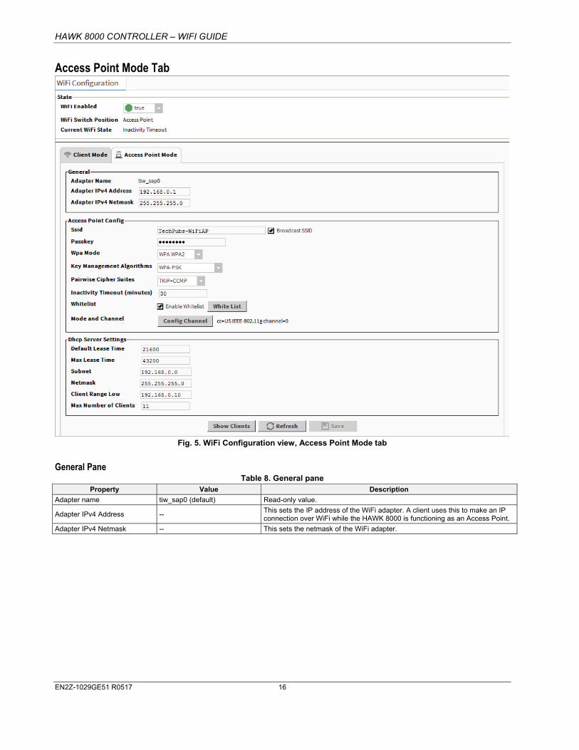
Access Point Mode Tab
Fig. 5. WiFi Configuration view, Access Point Mode tab
General Pane Table 8. General pane
Property Value Description
Adapter name tiw_sap0 (default) Read-only value.
Adapter IPv4 Address -- This sets the IP address of the WiFi adapter. A client uses this to make an IP connection over WiFi while the HAWK 8000 is functioning as an Access Point.
Adapter IPv4 Netmask -- This sets the netmask of the WiFi adapter.

HAWK 8000 CONTROLLER – WIFI GUIDE
EN2Z-1029GE51 R0517 17
Access Point Config Pane Table 9. Access Point Config pane
Type Value Description
Ssid titan (default)
Service Set Identifier is a unique alphanumeric identifier. Sets the name for this access point. Replace default name with a unique, meaningful network name.
NOTE: It is important to change the default value to a unique name to avoid having multiple HAWK 8000 controllers with the same SSID in a particular area.
Broadcast SSID enabled (default), disabled
If enabled, periodically broadcasts WiFi signal so that devices can detect and connect.
If disabled, the SSID is "hidden" and not discoverable, and a client must be manually configured with the correct SSID matching the HAWK 8000's Ssid field above.
Passkey -- Sets a password that a client must enter to connect to this network. Strong password required
Wpa Mode WPA, WPA2, WPA WPA2 (default)
WiFi security protocols and security certification programs. WPA WPA2 will accommodate most devices. Devices with older network cards may only work with WPA security.
Key Management Algorithms WPA-PSK (default), WPA-EAP, WPA-PSK WPA-EAP
Methods of authentication key distribution and the encryption protocols that protect passwords via encryption using either a pre-shared key and/or an authentication server.
Pairwise Cipher Suites TKIP, CCMP, TKIP CCMP (default)
Encryption protocol options. TKIP CCMP will accommodate most devices.
Inactivity Timeout (minutes) 10 (default)
Sets a limit on the amount of time a client connection can be inactive. On reaching the Timeout limit, the WiFi adapter is shutdown completely. To restart it you must move the WiFi Configuration Switch on the housing to "OFF". Once the WiFi Current State shows "Stopped", move the WiFi Configuration Switch back to "ACC".
NOTE: If the intended WiFi usage is for tool connectivity, then set this value to some small number of minutes. If the intended WiFi usage is for field bus integration, then set this value to "0" to disable the Timeout functionality.
CAUTION: An Access Point represents a potential target for cyber attack. Leaving the Access Point disabled by default is a security best practice.
Enable Whitelist disable (default), enable If enabled, only an address in the configured whitelist can connect. If disabled, connection to the access point is not limited to a specific range of devices.
Whitelist -- Allows you to configure the access point with a range of device MAC addresses that can connect.
Mode and Channel
Country code: two digit code
Radio mode: 802.11a/b/g/n
Bandwidth: HT20, HT40, HT20 HT40
Channel number: (number of channel options depends on selected radio mode)
Once it is configured, County Code is a read-only value.
The Config Channel button invokes the Configure Mode and Channel dialog, which you can use to modify radio mode, bandwidth, and channel selections.
CAUTION: Configuring a County Code is a permanent change to the HAWK 8000 that cannot be altered.
HAWK 8000 CONTROLLER – WIFI GUIDE
EN2Z-1029GE51 R0517 18
Dhcp Server Settings Pane Table 10. Dhcp Server Settings pane
Type Value Description
Default Lease Time 21600 (default) Fixed duration (in seconds) for a DHCP IP address lease, before it expires the lease must be renewed.
Max Lease Time 43200 (default) Maximum duration (in seconds) for a DHCP IP address lease.
Subnet --
The subnet of IP addresses assigned by the DHCP server.
CAUTION: Configure this to assign addresses on a different subnet than that used in either of the HAWK 8000 controller's other LAN configurations, otherwise the ports will not function correctly.
Netmask -- The Netmask of IP addresses assigned by the DHCP Server.
Client Range Low --
Lowest IP address for the range. The order of assigning IPs from the Access Point DHCP is indeterminate.
NOTE: The adapter IP should be in the same subnet, but not in the range of addresses defined here.
Max Number of Clients 11 (default) Maximum number of WiFi clients that can attach at a given time (maximum limit is 16)
Supported WiFi Configurations WiFi Client and Access Point modes add support for a number of new network configurations. Supported network configurations are described in the following examples.
NOTE: Although other network configurations may exist they are not necessarily supported.
The HAWK 8000 controller does not support IP routing between any combination of Ethernet and WiFi ports. The HAWK 8000 will not forward IP packets from LAN1 to LAN2, LAN1 to WiFi, WiFi to LAN2, etc. If an installation requires IP routing between WiFi and Ethernet ports, it may be configured using standard IT networking infrastructure components.
In the following figures, different networks are represented by thick gray lines. The HAWK 8000 does not route traffic between different networks. Data may be shared at the application level.
WiFi Access Point for Local Tool Connections In this configuration, the HAWK 8000 Access Point feature is turned ON temporarily to provide a browser or COACH NX with access to the platform and/or station running on the HAWK 8000. The Access Point may support 3 or more simultaneous tool connections.
When configured for Access Point mode, tools such as laptops and mobile devices can connect to the WiFi adapter and access all features available over a wired Ethernet connection. For example, a tablet device can view web pages, or a laptop running COACH NX can upgrade software.
CAUTION
Risk of cyber attack! ► An Access Point represents a potential target for cyber attack. Leaving the Access Point disabled by default is a
recommended security best practice.
When used for connecting tools, the WiFi may be left in disabled mode and then switched ON (using the WiFi Configuration Switch on the housing) only when a user needs access to the HAWK 8000. Additionally, a timeout period can be configured to disable the AP mode after a certain period of inactivity. On reaching this timeout limit, the WiFi adapter is shutdown completely. To restart it, you must move the WiFi Configuration Switch on the housing to "OFF". Once the WiFi Current State shows "Stopped", move the WiFi Configuration Switch back to "ACC".

HAWK 8000 CONTROLLER – WIFI GUIDE
EN2Z-1029GE51 R0517 19
Fig. 6. WiFi Access Point for local tools
LEGEND: 1 COACH NX B
2 Supervisor
3 COACH NX A
4 Tablet A
5 HAWK 8000 WiFi Access Point
In the above figure,
• COACH NX A and Tablet A can access both the station and the platform on the HAWK 8000. • COACH NX A and Tablet A cannot access the Supervisor since it is on a different network. • COACH NX B and Supervisor can access the station and the platform on the HAWK 8000 via the wired Ethernet connection.
WiFi Access Point for Field Bus Device Integration In this configuration, the HAWK 8000 Access Point feature is turned ON permanently in order to provide a network for WiFi enabled field bus devices, such as actuators, sensors, thermostats, etc. This Access Point can also be used by other HAWK 8000 controllers that are configured for WiFi Client mode.
Both field bus devices and tools (laptop/mobile devices) can connect via the Access Point. Up to 16 devices are supported. However, if the maximum limit of 16 devices are connected then no tool access would be available.
In this configuration, the Access Point must always remain enabled so that tools and field bus devices can connect.

HAWK 8000 CONTROLLER – WIFI GUIDE
EN2Z-1029GE51 R0517 20
Fig. 7. WiFi Access Point for WiFi Field Bus
LEGEND: 1 COACH NX B
2 Supervisor
3 HAWK 8000 WiFi Access Point
4 COACH NX A
5 WiFi Field Bus Device A
6 WiFi Field Bus Device B
7 WiFi Field Bus Device C
In the above figure:
• COACH NX A can access the HAWK 8000. Also, the laptop can directly access WiFi field bus devices A, B, and C using appropriate software. If the field bus devices are other HAWK 8000 Clients, then COACH NX A can also directly access.
• COACH NX B and the Supervisor can access the HAWK 8000 via the wired link, but do not have direct access to WiFi field bus devices.
• Additionally, HAWK 8000 applications can read/write data from both networks.
WiFi Client In this configuration, the HAWK 8000 functions as a WiFi Client using an existing IT WiFi access point to gain access to a network. Also, one of the Ethernet ports on the HAWK 8000 is used to connect some Ethernet-based field bus devices.

HAWK 8000 CONTROLLER – WIFI GUIDE
EN2Z-1029GE51 R0517 21
NOTE: HAWK 8000 controllers deployed in the U.S. (and in countries that accept U.S. certification) and configured for Client mode cannot connect to an access point that uses Dynamic Frequency Selection (DFS) channels in the 5 GHz range. Unsupported DFS channels are listed here: 52, 56, 60, 64, 100, 104, 108, 112, 116, 132, 136, 140.
Fig. 8. HAWK 8000 as a WiFi Client
LEGEND: 1 COACH NX B
2 Supervisor
3 Tablet A
4 COACH NX A
5 HAWK 8000 WiFi Client
6 Ethernet Field Bus Device A
7 Ethernet Field Bus Device B
In the above figure:
• COACH NX A, Tablet A, COACH NX B, and the Supervisor can all connect to the HAWK 8000 using the IT networking infrastructure.
All traffic not on the local subnet is routed through the default gateway on the HAWK 8000. This includes any broadcast traffic (Discovery) from the HAWK 8000. This means that if gateway switching is "enabled" on the HAWK 8000 AND the Access Point provides a new default route in its configuration response to the HAWK 8000, then all non-local network traffic and broadcasts are routed to the Access Point and not to the field bus Ethernet when the HAWK 8000 is attached to the WiFi network. It also means that the supervisor should be able to "discover and learn" the HAWK 8000.
Conversely, if switching is disabled, the default gateway will stay pointing at the default gateway in the TCP/IP configuration of the HAWK 8000, regardless of any default route provided by the Access Point. This means that the supervisor / COACH NX need to be on the same subnet as the HAWK 8000, and any "discovery or learning" (which requires broadcasts and/or responses to broadcasts by the HAWK 8000) will not be possible because all the responses will be sent to the field bus network (which is still the default gateway).

HAWK 8000 CONTROLLER – WIFI GUIDE
EN2Z-1029GE51 R0517 22
NOTE: Although discovery (broadcast) will not work, you can still add devices manually.
• The HAWK 8000 can communicate with field bus devices. • Other devices on the IT network cannot connect directly to the field bus devices, since they are on a separate network.

HAWK 8000 CONTROLLER – WIFI GUIDE
EN2Z-1029GE51 R0517 23
GLOSSARY
access point
In a wireless local area network (WLAN), a wireless access point (WAP) is a hardware device, such as the HAWK 8000, that allows wireless devices to connect to a wired network using WiFi, or related standards. WAPs feature radio transmitters and antennae, which facilitate connectivity between devices and the Internet or a network.
client
A wireless client is a device that has the capability to use the 802.11 protocol. For example, a client may be a hardware device such as a HAWK 8000, a laptop, a PC, or WiFi phone. A client may be fixed, mobile, or portable. In wireless networking terminology, the terms "station," "wireless client," and "node" are often used interchangeably.
EAP EAP (Extensible Authentication Protocol) is an enterprise level authentication protocol that requires an authentication server. This is an additional security layer providing protection against attacks on passwords.
IEEE 802.1x An IEEE (Institute of Electrical and Electronics Engineers) standard for Portbased Network Access Control (PNAC) that is part of the IEEE 802.1 group of networking protocols. It provides an authentication mechanism for devices seeking to attach to a LAN or WLAN.
PSK Referred to as WPA-PSK (WiFi protected access-pre-shared key) mode, is a method of authentication key distribution.
SAP In the context of the HAWK 8000 Access Point mode of operation, the term "SAP" is synonymous with "access point", "host mode", or "hostapd". In this context, the terms may be used interchangeably.
STA In the context of the HAWK 8000 Client mode of operation, the term "STA" is synonymous with "client", "station", "station mode", or "wpa_supplicant." In this context, these terms may be used interchangeably.
TKIP TKIP (Temporal Key Integrity Protocol) is an encryption protocol. The RC4 stream cipher is used with a 128-bit per-packet key, dynamically generates a new key for each packet. Used by WPA.
TLS TLS (Transport Layer Security) is a cryptographic protocol that provides communication security over the Internet.
SSID
SSID (Service Set Identifier), an alphanumeric string (up to 32 characters), is a unique identifier for a specific WiFi access point. The SSID differentiates one WLAN from another. If the access point is configured to periodically broadcast its SSID, the wireless devices that are within range can detect the network and connect to it. When broadcasting is disabled, a wireless client must be configured with the network's SSID in order to connect to it.
Whitelist A layer of protection that can be added to a WiFi network. An IP address can be re-assigned to any device but a MAC address is hard-coded to the device. A MAC whitelist is an inventory of known MAC addresses that are permitted access to the WiFi access point.
WPA WPA2
WPA (Wi-Fi Protected Access)/WPA2 (Wi-Fi Protected Access I) are two WiFi security protocols and security certification programs. They provide both security (you can control who connects) and privacy (the transmissions cannot be read by others) for communications as they travel across your network. WPA2 is newer, more secure and complex than WPA. Newer Wi-Fi devices (certified since 2006) support both the WPA and WPA2 security protocols. Devices that have older network cards may only work with WPA security.
HAWK 8000 CONTROLLER – WIFI GUIDE
Manufactured for and on behalf of the Environmental & Energy Solutions Division of Honeywell Technologies Sàrl, Rolle, Z.A. La Pièce 16, Switzerland by its Authorized Representative:
CentraLine Honeywell GmbH Böblinger Strasse 17 71101 Schönaich, Germany Phone +49 (0) 7031 637 845 Fax +49 (0) 7031 637 740 [email protected] www.centraline.com
Subject to change without notice EN2Z-1029GE51 R0517
RELATED TECHNICAL LITERATURE Table 11. Related Technical Literature
Title Product
Literature no.
HAWK 8000 – Installation & Comm. Instructions EN1Z-1016GE51
HAWK 8000 – Product Data EN0Z-1016GE51
HAWK 8000 – Mounting Instructions MU1Z-1016GE51
HAWK 8000 – Installation & Startup Guide EN1Z-1027GE51
HAWK 8000 – Backup & Restore Guide EN2Z-1027GE51
HAWK 8000 – PICS EN0Z-1028GE51
HAWK 8000 – WiFi Guide EN2Z-1029GE51
HON-NXEM-xxx Expansion Modules – M.I. MU1Z-1031GE51
Panel Bus I/O Modules – Product Data EN0Z-0979GE51