haskel liquid pumps booklet 7-1
DESCRIPTION
BOMBA HASKELTRANSCRIPT
Pneumatic Driven Liquid Pumps
Pressure on Demand

H i g h P r e s s u r e
Haskel pneumatic driven liquid pumps are designed to provide a safe, reliable and economical, source of hydraulic pressure.
This brochure introduces our pneumatic driven liquid pump range. Visit our website at www.haskel.com for more information or to locate a distributor.
• Safe pneumatic operation – no heat, flame or spark risk
• Up to 100,000 psi (7000 bar) capability
• Infinitely variable cycling speed
• Stall feature at pre-determined pressure to hold that pressure without consuming power
• Problem-free stop/start applications
• Easily automated – many modification and control options
• Suitable for most liquids and liquefied gases
• Alternative gas drive options – sour gas, natural gas, boil off gases, nitrogen
• No need for air line lubrication – saves costs and prevents contamination
• Robust, reliable, compact and easy to maintain proven design
• Unbalanced cycling spool provides immediate response to pressure changes
• Also available in standard, or custom built power pac configurations
• Excellent worldwide service for spares and repairs
• Can be manufactured to meet ATEX, CE and NACE
Why Use Haskel Pneumat ic Dr iven Pumps?
Our pumps offer many advantages over electrically driven pumps:
A p p l i c a t i o n s i n c l u d e :
• Pressure testing
• Work holding/power clamping
• Jacking/lifting
• Valve actuator control
• Hydraulic cylinder actuation
• Press safety overload devices
• Roller tensioning
• Metering
• Precision lubrication and spraying
• Liquefied gas transfer
www.haskel.com2

www.haskel.com
P r e s s u r e a n d F l o w o n D e m a n d
This guide will help you to pre-select the pump ideally suited for your application. If you have specific questions, however, we urge you to provide Haskel with the operational details of your application. We will recommend a model and any corresponding accessories.
O u t p u t H o r s e p o w e r R a t i n g s
The pumps are categorized on their horsepower ratings (see pages 6-7). These are approximate and peak at 100 psi (7 bar), assuming adequate drive, pressure and volume. Peak horsepower is at about 75% nominal ratio x drive pressure, i.e. 100:1 pump @ 100 psi air drive peaks at 100 x 100 = 10000 x 0.75 psi = 7500 psi (517 bar) hydraulic pressure.
D o u b l e a n d T r i p l e A i r H e a d P u m p s
Performance can be extended for the 1.5 hp pumps by stacking air pistons without changing the hydraulic piston. Haskel multi-head pumps consume less air than competitive single head pumps of the same area, as only one head is pressurized on the return stroke; e.g., on a 1.5 hp pump additional heads can raise performance to 2 hp.
Double air head pumps are identified by the last digit 2 in the pump model number. Thus, a nominal 50:1 ratio pump with two air heads is described as a 52. Similarly, a triple air head pump is identified with a last digit 3. Thus, a 900 ratio pump with three air heads is described as a 903.
O p e r a t i o n
The pumps automatically reciprocate on a differential piston principle. A large piston driven by relatively low pressure drive acts directly upon a smaller hydraulic piston.
The nominal ratio between piston sizes is indicated in the model coding and approximates to the maximum working pressure. The actual ratio is about 15% above nominal so that the pump continues to cycle when drive pressure equals nominal ratio. Initially, the pump will cycle at maximum speed acting as a transfer pump to pressurize downstream.
It will cycle at a slower rate as the fluid meets resistance until it stalls at maximum output pressure. When a pressure drop downstream occurs, it will recycle as necessary in an effort to maintain maximum pressure. Stall pressure is achieved when the outlet pressure rises and offers more resistance to the reciprocating differential piston assembly. The piston assembly then stalls when the forces balance, e.g. when drive pressure x drive piston area equals outlet (stall) pressure x driven hydraulic plunger area. The pump design is sensitive to very small pressure drops due to the low frictional resistance of the large diameter drive piston and hydraulic piston seals.
3
S i n g l e D r i v e H e a d P u m p
D o u b l e A i r H e a d P u m p
T r i p l e A i r H e a d P u m p
Nominal Ratio * (2) Indicates Double Drive Piston** (3) Indicates Triple Drive Piston
0.65 sq in (4 sq cm)Therefore, actual ratio = 40:1Nominal Ratio = 35:1
25.9 sq in (167 sq cm)
Area .65 sq in (4 sq cm)Therefore, actual ratio = 79:1Nominal Ratio = 72:1*
Area 25.2 sq in (163 sq cm)
Area 25.9 sq in (167 sq cm)
Area .65 sq in (4 sq cm)Therefore, actual ratio = 118:1Nominal Ratio = 103:1**
Area 25.2 sq in (163 sq cm)
Area 25.2 sq in (163 sq cm)
Area 25.9 sq in (167 sq cm)
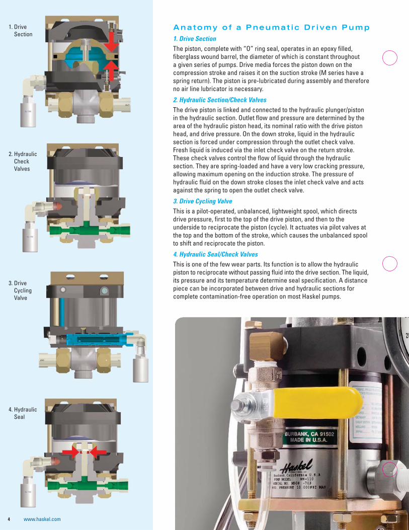
Anatomy of a Pneumat ic Dr iven Pump
1. Drive SectionThe piston, complete with “O” ring seal, operates in an epoxy filled, fiberglass wound barrel, the diameter of which is constant throughout a given series of pumps. Drive media forces the piston down on the compression stroke and raises it on the suction stroke (M series have a spring return). The piston is pre-lubricated during assembly and therefore no air line lubricator is necessary.
2. Hydraulic Section/Check ValvesThe drive piston is linked and connected to the hydraulic plunger/piston in the hydraulic section. Outlet flow and pressure are determined by the area of the hydraulic piston head, its nominal ratio with the drive piston head, and drive pressure. On the down stroke, liquid in the hydraulic section is forced under compression through the outlet check valve. Fresh liquid is induced via the inlet check valve on the return stroke. These check valves control the flow of liquid through the hydraulic section. They are spring-loaded and have a very low cracking pressure, allowing maximum opening on the induction stroke. The pressure of hydraulic fluid on the down stroke closes the inlet check valve and acts against the spring to open the outlet check valve.
3. Drive Cycling ValveThis is a pilot-operated, unbalanced, lightweight spool, which directs drive pressure, first to the top of the drive piston, and then to the underside to reciprocate the piston (cycle). It actuates via pilot valves at the top and the bottom of the stroke, which causes the unbalanced spool to shift and reciprocate the piston.
4. Hydraulic Seal/Check ValvesThis is one of the few wear parts. Its function is to allow the hydraulic piston to reciprocate without passing fluid into the drive section. The liquid, its pressure and its temperature determine seal specification. A distance piece can be incorporated between drive and hydraulic sections for complete contamination-free operation on most Haskel pumps.
4 www.haskel.com
1. Drive Section
2. Hydraulic Check Valves
3. Drive Cycling Valve
4. Hydraulic Seal
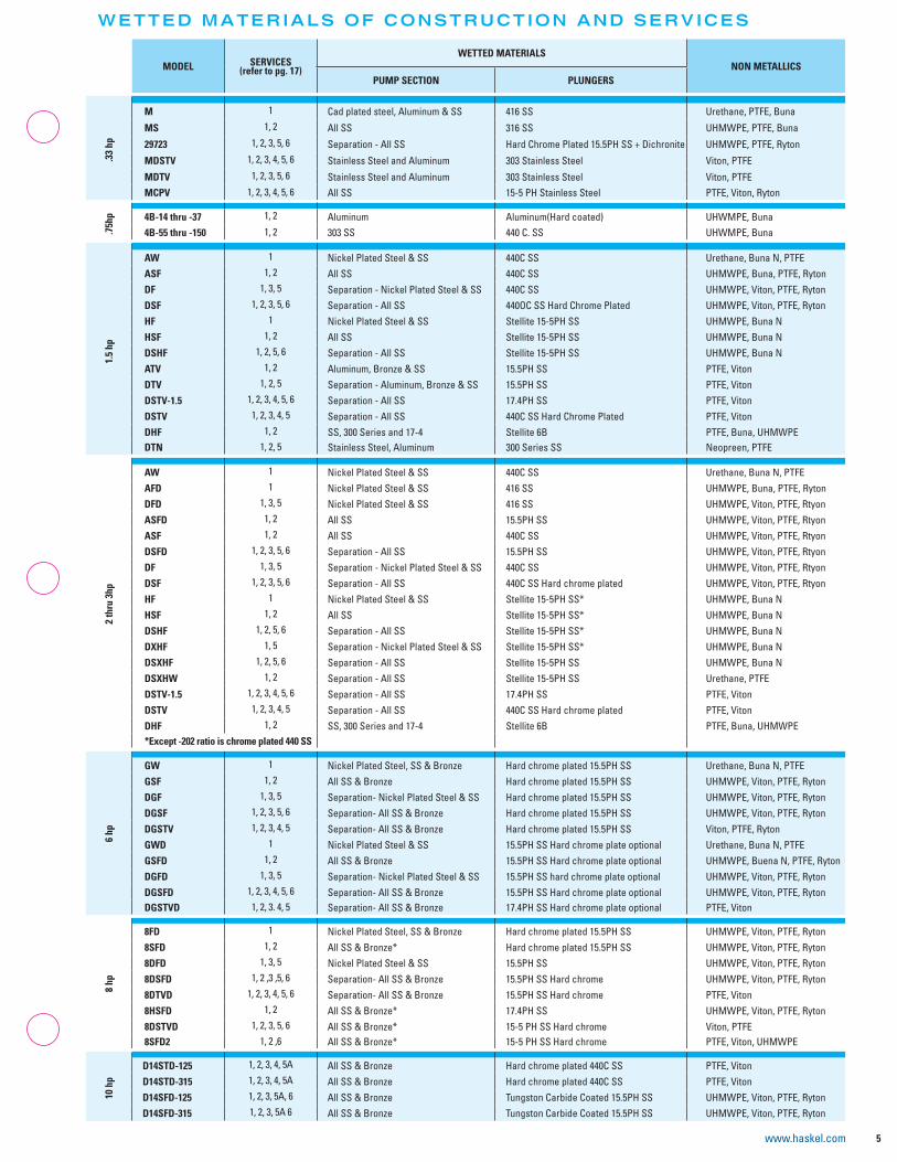
WETTED MATERIALS OF CONSTRUCTION AND SERVICES
5www.haskel.com
MODEL SERVICES(refer to pg. 17)
WETTED MATERIALSNON METALLICS
PUMP SECTION PLUNGERS
.33
hpM 1 Cad plated steel, Aluminum & SS 416 SS Urethane, PTFE, Buna
MS 1, 2 All SS 316 SS UHMWPE, PTFE, Buna
29723 1, 2, 3, 5, 6 Separation - All SS Hard Chrome Plated 15.5PH SS + Dichronite UHMWPE, PTFE, Ryton
MDSTV 1, 2, 3, 4, 5, 6 Stainless Steel and Aluminum 303 Stainless Steel Viton, PTFE
MDTV 1, 2, 3, 5, 6 Stainless Steel and Aluminum 303 Stainless Steel Viton, PTFE
MCPV 1, 2, 3, 4, 5, 6 All SS 15-5 PH Stainless Steel PTFE, Viton, Ryton
.75h
p 4B-14 thru -37 1, 2 Aluminum Aluminum(Hard coated) UHWMPE, Buna
4B-55 thru -150 1, 2 303 SS 440 C. SS UHWMPE, Buna
1.5
hp
AW 1 Nickel Plated Steel & SS 440C SS Urethane, Buna N, PTFE
ASF 1, 2 All SS 440C SS UHMWPE, Buna, PTFE, Ryton
DF 1, 3, 5 Separation - Nickel Plated Steel & SS 440C SS UHMWPE, Viton, PTFE, Ryton
DSF 1, 2, 3, 5, 6 Separation - All SS 440OC SS Hard Chrome Plated UHMWPE, Viton, PTFE, Ryton
HF 1 Nickel Plated Steel & SS Stellite 15-5PH SS UHMWPE, Buna N
HSF 1, 2 All SS Stellite 15-5PH SS UHMWPE, Buna N
DSHF 1, 2, 5, 6 Separation - All SS Stellite 15-5PH SS UHMWPE, Buna N
ATV 1, 2 Aluminum, Bronze & SS 15.5PH SS PTFE, Viton
DTV 1, 2, 5 Separation - Aluminum, Bronze & SS 15.5PH SS PTFE, Viton
DSTV-1.5 1, 2, 3, 4, 5, 6 Separation - All SS 17.4PH SS PTFE, Viton
DSTV 1, 2, 3, 4, 5 Separation - All SS 440C SS Hard Chrome Plated PTFE, Viton
DHF 1, 2 SS, 300 Series and 17-4 Stellite 6B PTFE, Buna, UHMWPE
DTN 1, 2, 5 Stainless Steel, Aluminum 300 Series SS Neopreen, PTFE
2 th
ru 3
hp
AW 1 Nickel Plated Steel & SS 440C SS Urethane, Buna N, PTFE
AFD 1 Nickel Plated Steel & SS 416 SS UHMWPE, Buna, PTFE, Ryton
DFD 1, 3, 5 Nickel Plated Steel & SS 416 SS UHMWPE, Viton, PTFE, Rtyon
ASFD 1, 2 All SS 15.5PH SS UHMWPE, Viton, PTFE, Rtyon
ASF 1, 2 All SS 440C SS UHMWPE, Viton, PTFE, Rtyon
DSFD 1, 2, 3, 5, 6 Separation - All SS 15.5PH SS UHMWPE, Viton, PTFE, Rtyon
DF 1, 3, 5 Separation - Nickel Plated Steel & SS 440C SS UHMWPE, Viton, PTFE, Rtyon
DSF 1, 2, 3, 5, 6 Separation - All SS 440C SS Hard chrome plated UHMWPE, Viton, PTFE, Rtyon
HF 1 Nickel Plated Steel & SS Stellite 15-5PH SS* UHMWPE, Buna N
HSF 1, 2 All SS Stellite 15-5PH SS* UHMWPE, Buna N
DSHF 1, 2, 5, 6 Separation - All SS Stellite 15-5PH SS* UHMWPE, Buna N
DXHF 1, 5 Separation - Nickel Plated Steel & SS Stellite 15-5PH SS* UHMWPE, Buna N
DSXHF 1, 2, 5, 6 Separation - All SS Stellite 15-5PH SS UHMWPE, Buna N
DSXHW 1, 2 Separation - All SS Stellite 15-5PH SS Urethane, PTFE
DSTV-1.5 1, 2, 3, 4, 5, 6 Separation - All SS 17.4PH SS PTFE, Viton
DSTV 1, 2, 3, 4, 5 Separation - All SS 440C SS Hard chrome plated PTFE, Viton
DHF 1, 2 SS, 300 Series and 17-4 Stellite 6B PTFE, Buna, UHMWPE
*Except -202 ratio is chrome plated 440 SS
6 hp
GW 1 Nickel Plated Steel, SS & Bronze Hard chrome plated 15.5PH SS Urethane, Buna N, PTFE
GSF 1, 2 All SS & Bronze Hard chrome plated 15.5PH SS UHMWPE, Viton, PTFE, Ryton
DGF 1, 3, 5 Separation- Nickel Plated Steel & SS Hard chrome plated 15.5PH SS UHMWPE, Viton, PTFE, Ryton
DGSF 1, 2, 3, 5, 6 Separation- All SS & Bronze Hard chrome plated 15.5PH SS UHMWPE, Viton, PTFE, Ryton
DGSTV 1, 2, 3, 4, 5 Separation- All SS & Bronze Hard chrome plated 15.5PH SS Viton, PTFE, Ryton
GWD 1 Nickel Plated Steel & SS 15.5PH SS Hard chrome plate optional Urethane, Buna N, PTFE
GSFD 1, 2 All SS & Bronze 15.5PH SS Hard chrome plate optional UHMWPE, Buena N, PTFE, Ryton
DGFD 1, 3, 5 Separation- Nickel Plated Steel & SS 15.5PH SS hard chrome plate optional UHMWPE, Viton, PTFE, Ryton
DGSFD 1, 2, 3, 4, 5, 6 Separation- All SS & Bronze 15.5PH SS Hard chrome plate optional UHMWPE, Viton, PTFE, Ryton
DGSTVD 1, 2, 3. 4, 5 Separation- All SS & Bronze 17.4PH SS Hard chrome plate optional PTFE, Viton
8 hp
8FD 1 Nickel Plated Steel, SS & Bronze Hard chrome plated 15.5PH SS UHMWPE, Viton, PTFE, Ryton
8SFD 1, 2 All SS & Bronze* Hard chrome plated 15.5PH SS UHMWPE, Viton, PTFE, Ryton
8DFD 1, 3, 5 Nickel Plated Steel & SS 15.5PH SS UHMWPE, Viton, PTFE, Ryton
8DSFD 1, 2 ,3 ,5, 6 Separation- All SS & Bronze 15.5PH SS Hard chrome UHMWPE, Viton, PTFE, Ryton
8DTVD 1, 2, 3, 4, 5, 6 Separation- All SS & Bronze 15.5PH SS Hard chrome PTFE, Viton
8HSFD 1, 2 All SS & Bronze* 17.4PH SS UHMWPE, Viton, PTFE, Ryton
8DSTVD 1, 2, 3, 5, 6 All SS & Bronze* 15-5 PH SS Hard chrome Viton, PTFE
8SFD2 1, 2 ,6 All SS & Bronze* 15-5 PH SS Hard chrome PTFE, Viton, UHMWPE
10 h
p
D14STD-125 1, 2, 3, 4, 5A All SS & Bronze Hard chrome plated 440C SS PTFE, Viton
D14STD-315 1, 2, 3, 4, 5A All SS & Bronze Hard chrome plated 440C SS PTFE, Viton
D14SFD-125 1, 2, 3, 5A, 6 All SS & Bronze Tungston Carbide Coated 15.5PH SS UHMWPE, Viton, PTFE, Ryton
D14SFD-315 1, 2, 3, 5A 6 All SS & Bronze Tungston Carbide Coated 15.5PH SS UHMWPE, Viton, PTFE, Ryton

Performance and Speci f ica t ion Overv iew
6
Max
Air
Air
Hea
d
Pow
er
Pump Model Code Ratio Dashno.
Actual AreaRatio
Maximum Rated Output PressureDisplacement/Cycle Maximum Flow
Continuous Intermittent
psi bar psi bar cu in ml cu in/min l/min
125
psi/8
.6 b
ar
Sing
le
0.33
hp
M, MDSTV, MDTV -5 5 625 43 625 43 0.83 13.6 506 8.30
M, MS-7 7.1 900 62 900 62 0.60 9.8 366 6.00-12 10.5 1500 103 1500 103 0.36 5.9 234 3.83
M, MCPV, MS, 29723
-21 22 2600 179 2600 179 0.20 3.3 130 2.13-36 37 4500 310 4500 310 0.12 2.0 78 1.28-50 58 6500 448 6500 448 0.088 0.40 57 0.934-71 75 8800 607 8800 607 0.06 1.0 39 0.64-110 112 13500 931 13500 931 0.039 0.60 25 0.42
M, MCPV, MS -188 192 15000 1034 15000 1034 0.023 0.40 18 0.2929723, MCPV -188 217 10000 1034 10000 1034 0.023 0.40 18 0.29
MS -220 210 20000 1380 25000 1723 0.021 0.34 14 0.22
100
psi/7
bar
Sing
le
0.75
hp
4B
-14 16 1500 103 1500 103 0.9 14.7 428 7.01-21 24 2300 159 2300 159 0.6 9.8 285 4.67-25 29 2700 186 2700 186 0.5 8.2 238 3.89-30 34 3200 221 3200 221 0.43 7.0 204 3.35-37 42 3800 262 3800 262 0.35 5.7 166 2.72-55 63 6000 414 6000 414 0.22 3.6 105 1.71-75 86 7800 538 7800 538 0.17 2.8 81 1.32-100 114 10600 731 10600 731 0.13 2.0 62 1.01-150 171 15000 1034 15000 1034 0.088 1.44 42 0.68
150
psi/1
0.5
bar
Sing
le
1.5
hp
DSTV -1.5 1.6 160 11 300 21 31.90 513 5104 83.6ATV, DTN, DTV -4 4.6 690 48 1200 83 20.00 328 3200 52.4
AW, ASF. DF. DSF.DSTV
-B10 11.5 1600 110 1600 110 4.05 66.4 1215 19.9-B15 17 2400 165 2400 165 2.70 44.3 810 13.3-25 29 4000 276 4000 276 1.62 26.6 486 8.0-35 40 5700 393 5700 393 1.16 19.0 348 5.7-60 69 9800 676 9800 676 0.67 11.0 201 3.3-100 115 15000 1034 16500 1138 0.41 6.7 123 2.0-150 173 15000 1034 20000 1379 0.27 4.5 81 1.3
HF, HSF, DHF.DSHF-151 173 25000 1724 25000 1724 0.27 4.5 81 1.3-225 260 30000 2069 37000 2552 0.18 3.0 41 0.7-300 345 30000 2069 50000 3448 0.14 2.3 32 0.5
HF -450 533 45000 3103 45000 3103 0.0 1.5 20 0.3
Dou
ble
2 hp
ATV -8 9.2 850 59 1200 83 20 328 3200 52.4
AW, ASF. DF. DSF.DSTV
-B22 23 3200 221 3200 221 4.05 66.4 1215 19.9-B32 34 4800 331 4800 331 2.70 44.3 810 13.3-52 57 5000 345 8000 552 1.62 26.6 488 8.0-72 80 11000 759 11000 759 1.16 19.0 348 5.7-122 138 15000 1034 19000 1310 0.67 11.0 201 3.3
HF, HSF, DHF.DSHF-202 230 30000 2069 33000 2276 0.41 6.7 92 1.5-302 346 30000 2069 50000 3448 0.27 4.5 61 1.0
DXHF, DSXHF-452 520 30000 2069 70000 4828 0.18 3.0 41 0.7-602 690 30000 2069 75000 5172 0.14 2.3 32 0.5
100
psi/7
bar
Trip
le
2 hp
DXHF, DSXHF-683 780 30000 2069 70000 4828 0.18 3.0 25 0.41-903 1038 30000 2069 75000 5172 0.14 2.3 20 0.33
DSXHW -1373 1575 30000 2069 100000 6897 0.086 1.4 12 0.197
Sing
le
2.2 AFD-DFD-ASFD-DSFD -B60 69 6500 448 6500 448 1.34 2.2 369 6.0
150
psi/1
0.5
bar
3 hp ASFD
-10 11.5 1600 110 1600 110 8.10 133 1823 29.9-15 17 2400 165 2400 165 5.40 89 1215 19.9-25 29 4000 276 4000 276 3.24 53.6 729 11.9-35 40 5700 393 5700 393 2.32 38.0 522 8.6-60 69 9800 676 9800 676 1.34 22.0 302 4.9-100 115 15000 1034 16500 1138 0.82 13.4 185 3.0-150 173 15000 1034 20000 1379 0.54 9.0 122 2.0-202 230 30000 2069 33000 2276 0.82 13.4 144 2.4
125
psi/8
.6 b
ar
6 hp
GWD,GSFD.DGFD,DGSFD,DGSTVD -12 14.8 1850 128 4000 276 15.9 260 5009 82.1
GW,DGF,GSF,DGSF,DGSTV
-35 40.3 4375 302 4375 302 6.0 98 1890 31.0-60 69 7500 517 7500 517 3.5 57 1103 18.1-100 115 8000 552 10000 690 2.1 34 662 10.8
8 hp
8SFD,8DSFD,8DSTVD -25 27.5 3575 246 4000 276 14.0 229 2660 43.5
8SFD-40 43.5 6000 414 6000 414 8.90 145 1691 28.0-65 73 10000 690 10000 690 5.40 88 1026 17.0
8DSFD -100 112 10000 690 10000 690 3.52 58 669 11.08HSFD -225 253 25000 1724 25000 1724 1.56 26 296 5.0
8SFD2(Double Air Drive Piston Models)
-55 55 5500 379 7200 497 14.14 232 1900 31.1-88 88 8800 607 10000 690 8.84 145 1182 19.36-224 225 25000 1724 25000 1724 3.53 58 476 7.6
10 h
p D14STD, D14SFD -125 138 16000 1103 16000 1103 8.80 144.2 704 11.5-315 347 36000 2483 36000 2483 3.50 57.4 280 4.6

7www.haskel.com
Typical Performance using 100 psi (7 bar) Air drive
Outlet Pressure Outlet Flow Outlet Pressure Outlet Flow
psi bar cu in/min l/min psi bar cu in/min l/min
225 15.5 500 8.20 415 29 249 4.09300 21 350 5.70 600 41 160 2.6700 48 200 3.28 1125 78 100 1.641500 103 90 1.48 2000 138 48.9 0.81700 117 70 1.15 3100 214 39.6 0.652450 169 tbd tbd 4500 310 tbd tbd
3000 207 40 0.64 6000 414 19 0.31
7500 517 20 0.33 10000 690 8.5 0.145000 345 18 0.30 10000 690 14 0.235000 345 18 0.30 10000 690 14 0.237500 517 15 0.24 15000 1034 12 0.2
700 48 400 6.55 1450 100 61 1.001000 69 270 4.42 2000 138 120 2.001250 86 230 3.77 2500 172 61 1.001500 103 200 3.28 3000 207 62 1.001750 121 170 2.78 3500 241 82 1.332000 138 110 1.80 5000 345 66 1.082500 172 87 1.42 7500 517 37 0.605000 345 57 0.93 10000 690 26 0.437500 517 37 0.60 15000 1034 7 0.11
50 3 5000 81.9 150 10 1000 16.4100 7 1953 32 400 28 750 12.3400 28 1000 16.4 990 68 500 8.19750 52 598 9.8 1600 110 200 3.281000 69 403 6.6 2500 172 195 3.22000 138 350 4.1 3600 248 98 1.63000 207 152 2.5 6200 427 50 0.824000 276 100 1.64 10000 690 24.4 0.47000 483 59.7 0.98 15000 1034 29.9 0.497000 483 59.7 0.98 15000 1034 29.9 0.497500 517 39.6 0.65 24000 1655 9.8 0.1615000 1034 29.9 0.49 27000 1862 20.1 0.3336000 2483 14.6 0.24 45000 3103 9.2 0.15
200 14 1953 32 800 28 750 12.3
400 28 799 13.1 2100 145 200 3.28
700 48 500 8.2 3000 207 152 2.50
1900 131 299 4.9 5000 345 98 1.60
2000 138 226 3.7 7500 517 50 0.82
4000 276 122 2.0 12000 828 40.2 0.66
7000 483 91.5 1.5 20000 1379 20.1 0.33
10000 690 45.2 0.7 30000 2069 15.2 0.25
10000 690 34.8 0.6 40000 2759 15.2 0.2515000 1034 24.4 0.4 50000 3448 12.2 0.2
15000 1034 19.5 0.32 60000 4138 4.9 0.0815000 1034 15.9 0.26 70000 4828 5.5 0.0916000 1103 9.2 0.15 90000 6207 3.1 0.05
1000 69 348 5.7 5500 379 152 2.5
500 34 1520 24.9 1000 69 380 6.22750 52 1030 16.9 1500 103 260 4.26
1000 69 662 10.9 2500 172 162 2.661500 1034 465 7.6 3500 248 100 1.643000 138 248 4.1 6000 414 56 0.925000 345 151 2.5 10000 690 41 0.677500 517 103 2.0 15000 1034 27 0.44
10000 690 63 1.0 20000 1379 47 0.77
200 14 5004 82 1200 83 1454 24
1000 69 1770 29 3500 241 600 9.8
2000 138 976 16 5500 379 397 6.5
2000 138 573 9.4 10000 690 195 3.2
1000 69 2400 39.3 2500 172 280 4.62000 138 1420 23.2 4000 276 200 3.273000 207 880 14.4 6000 414 310 5.085000 345 555 9.1 10000 690 163 2.6710000 690 270 4.4 20000 1379 144 2.362500 172 1230 20.1 4000 276 675 114000 276 850 13.9 5000 345 800 13.110000 690 315 5.2 18500 1276 140 2.3
8000 552 488 8.0 12000 828 195 3.215000 1034 238 3.9 30000 2069 79.3 1.3
P u m p S e l e c t i o n I n f o r m a t i o n
G u i d e l i n e s f o r C o n t i n u o u s D u t y A p p l i c a t i o n s f o r M a x i m i z i n g S e a l L i f e P e r f o r m a n c e
Pump Model Letter Coding
All Haskel pumps are identified by letters coding the type of pump, followed by a number indicating the practical working ratio of the drive area to the hydraulic plunger area. These letters are explained in the chart below.
M .875” stroke .33 hp miniature pump series
S Stainless steel hydraulic piston and body
29723 .33 hp Chemical Pump
D (Prefix) Pump incorporates a Distance Piece
D (Suffix) Double Acting pump
4B 1” stroke .75 hp pump series (bottom inlet only)
A 2” stroke 1.5 + 2 hp pump series
H 2” stroke 1.5 + 2 hp High Pressure pump series
-C Filter, regulator with gauge and shut-off/speed control valve
XH 2” stroke 1.5 + 2 hp Extreme High Pressure pump series
G 4.5” stroke 6 hp pump series
B 4.5” stroke 8 hp pump or booster series
14 4” stroke 10 hp pump series
W Polyurethane U-cup dynamic seal
F UHMWPE (Ultra-high Molecular Weight Polyethylene Dynamic Seal
T Reinforced Teflon® dynamic seal
V Viton® o-ring static seal
-B Bottom inlet
-CP Chemical Pump
Pump Series Maximum Cycles per Minute
0.3 hp 325 cpm
0.75 hp 225 cpm
1.5, 2.0 and 2.2 hp
(Single and Double Drive Piston)80 cpm
2.0 hp (Triple Drive Piston) 60 cpm
3.0 hp 80 cpm
6.0 hp 60 cpm
8.0 hp 50 cpm
10.0 hp 40 cpm

. 3 3 h p ( . 2 5 k W ) M S e r i e s P u m p M o d e l s
ModelNominalRatio
Displacementper Cycle
Maximum Working PressureConsult chart on page 6 for more informationregarding continuous/intermittent pressures.
Optional Modifications
Key Features• Choice of 6 models, 9 ratios,
27 possible combinations
• Flows to 2 gpm (7.5 l/min)
• Choice of wetted materials
• Single air head
• Drive pressure 25 to 125 psi (1.8 to 9 bar)
• Pressures to 25,000 psi (1724 bar)
• All Hydraulic fluids, water (plain or DI), solvents, mild chemicals, liquefied gases
8 www.haskel.com
M,MDSTV
-5 625 psi (43 bar) .83 cu in (13.6 ml)
M, MS -7 900 psi (62 bar) .6 cu in (9.8 ml)
-12 1500 psi (103 bar) .36 cu in (5.9 ml)
M, MS, -21 2600 psi (179 bar) .2 cu in (3.3 ml)
MCPV, -36 4500 psi (310 bar) .12 cu in (2.0 ml)
29723 -50 6500 psi (448 bar) .088 cu in (1.4 ml)
-71 8800 psi (607 bar) .06 cu in (1.0 ml)
M, MS -110 13500 psi (931 bar) .039 cu in (0.6 ml)
-188 15000 psi (1034 bar) .023 cu in (.4 ml)
MCPV, -110 10,000 psi (688 bar) .039 cu in (0.6 ml)
29723 -188 .023 cu in (.4 ml)
MS -220 25000 psi (1723 bar) .021 cu in (.34 ml)
For service codes, see page 17.For weights and dimensions, see page 18.
Number Description Number Description
-HP Hand pump attachment (with handle). Provides manual operation of pump for precision pressure control or use without air power
51809 Normally open air operated release with relief valve. Provides highest release flow capacity. Will hold full pump psi piloted from drive air. Vents are not threaded. Ref. drawing 56643 for tank top mounting parts.26082 Handle only.
26220-2 With handle. 51809-1 Normally closed air operated release with relief valve. Used to hold hydraulic jacks. Will release up to 11000 psi (using 100 psi air). Vents are not threaded. Ref. drawing 56643 for tank top mounting parts. Not available in 188:1 ratio.
26220-3 Without handle.Kits for converting existing units.
-V Manual release with relief valve. For M and MS pumps only. Provides high pressure needle valve with internal adjustable safety relief downstream of pump outlet checks. Tank return is 1⁄8” NPT in pump body.
51810 Safety relief valve. Relief is upstream of outlet check. Vent hole 1/16 NPT M or MS series -21 through 188.
51811 External air pilot. Provides 1⁄8” NPT port for external air to pilot for remote start/stop.26063-3 Dead Man valve. ¼” NPT port.
26064-3 Combination air regulator/filter with gauge. ¼” NPT port. 52340 Solid air cap.26065-3 Speed control valve. ¼” NPT port. 52950 Electric stroke counter provision. Micro switch (BZE6-2RQ) mounted on upper
cap trips with each cycle.26065-3 plus 26064-3
-C air controls installed on pump. ¼” NPT port.53175 Level II cleaning.53304 High pressure outlet port. Fits ¼” O.D. high pressure threaded and coned tube.
28320 Manifold mount inlet port. Provides O-ring boss in aluminum block to enable mounting on side of tank below oil level. Modification applies to M-21 through M-188 only.
53784 Piped exhaust (drive only). For field conversion of any .33 HP pump. Provides ¼” NPT exhaust port.
53935 Low temperature drive. Enables operation down to 5°F. Some sacrifice of seal life at normal temperature. M or MS series.28590 Palm or foot start/stop button drive. Spring loaded shut.
28700-1 Air OP release valve. 54179 Stroke adjuster (includes 29697 above). Useful for metering applications. Knurled knob with vertical scale on pump cap.28926 Remote start/stop control. Provides 1⁄8” NPT bleed signal port for single line remote
control. 57905 No return spring. Provides improved fill on suction stroke pumping liquefied gases by utilizing the inlet pressure. Only available on M and MS series.29002 Viton air drive.
29697 Single stroke from remote air pulse. Useful for metering applications. One stroke per air pulse signal; eliminates automatic cycling. 1⁄8” NPT signal port.
59888 Cycle timer installed.80103 Noise reduction kit fitted.
51331 EPR seals for liquid section for 29723-XX ratio pumps. 80348 SAE outlet for M-pumps, 3⁄8” SAE, 6500 psi (448 bar) max.51788 Piped exhaust – standard. Provides connection ports for drive and pilot exhausts.
Enables under tank top mounting and/or natural gas drive.81499 EPR Seals for M and MS series for Liquid Section.82367 SS trim for 1⁄3 hp drive
51794 Piped exhaust – sour gas. With hand pump (HP). 82500 ATEX Modification (Available on MS & 29723 but not M series).51794-2 Piped exhaust – sour gas. Without hand pump (HP). 85630 Conversion kit, new style exhaust muffler.51804 Muffler (for use with piped exhaust modifications below). ¼” NPT male port. 86337 Extended life air drive.

9www.haskel.com
Optional Modifications
Key Features• One model available
in 9 ratios
• Output pressures to 15,000 psi (1034 bar)
• Flows to 1.5 gpm (5.7 l/min)
• Choice of wetted materials
• Single air head
• Drive pressure 3 psi to 100 psi (.2 to 7 bar)
Number Description Number Description
-C Air drive controls. 59888 Cycle timer installed.56564 Extreme cycling service. Not recommended for long stall periods. 80637 SAE outlet fitting for ratio 37 to 100, 1⁄4” SAE, 6500 psi (448 bar) max.56594 External air pilot. Provides 1⁄8” NPT port for external air to pilot for remote start/
stop operation.81575 Changes the “F” seal to a “W” seal. Recommend for use with water.
82104 Viton air drive.57639 Low drive air pressure. Allows user to regulate drive air to as low as 3 psi (.2 bar). 82500 ATEX modification.57960 Single acting drive. Used for pumping liquefied gases under pressure. 86337 Extended life air drive.
58475 1⁄8” NPT port on drive for recycle valve connection.59354 Noise reduction kit fitted.
. 7 5 h p ( . 5 6 k W ) P u m p M o d e l s
ModelNominalRatio
Displacementper Cycle
Maximum Working PressureConsult chart on page 6 for more informationregarding continuous/intermittent pressures.
4B -14 1500 psi (103 bar) .9 cu in (14.8 ml)
-21 2300 psi (159 bar) .6 cu in (9.8 ml)
-25 2700 psi (186 bar) .5 cu in (8.2 ml)
-30 3200 psi (221 bar) .43 cu in (7.1 ml)
-37 3800 psi (262 bar) .35 cu in (5.7 ml)
-55 6000 psi (414 bar) .22 cu in (3.6 mil)
-75 7800 psi (538 bar) .17 cu in (2.8 ml)
-100 10600 psi (731 bar) .13 cu in (2.1 ml)
-150 15000 psi (1034 bar) .088 cu in (1.4 ml)
For service codes, see page 17.For weights and dimensions, see page 18.

1 . 5 h p ( 1 . 1 2 k W ) P u m p M o d e l s1 . 5 h p ( 1 . 1 2 k W ) P u m p M o d e l sModel
NominalRatio
Displacementper Cycle
Maximum Working PressureConsult chart on page 6 for more informationregarding continuous/intermittent pressures.
Optional Modifications
Key Features• Choice of 11 models,
13 ratios, 50 possible combinations
• Output pressures to 50,000 psi (3448 bar)
• Flows to 22 gpm (83.0 l/min)
• Choice of wetted materials
• Single air head
• Drive pressure 3 to 150 ps (.2 to 10 bar) (1) These series are “Lift” pumps and maximum outlet
pressure is (air drive x pump ratio) + inlet pressure
(2) DTV has poppet checks
10 www.haskel.com
DSTV(1) -1.5 160 psi (11 bar) 31.9 cu in (513.0 ml)
ATV, -4 1200 psi (83 bar) 20.0 cu in (328.0 ml)
DTV(1) (2)
DTN(1)
AW, ASF, -B10 1600 psi (110 bar) 4 cu in (66.4 ml)
DF, DSF, -B15 2400 psi (165 bar) 2.7 cu in (44.3 ml)
DSTV -25 4000 psi (276 bar) 1.6 cu in (26.6 ml)
-35 5700 psi (393 bar) 1.2 cu in (19 ml)
-60 9800 psi (676 bar) .7 cu in (11 ml)
ATV -8 850 psi (59 bar) 20 cu in (328.0 ml)
AW, ASF, -100 16500 psi (1138 bar) .4 cu in (6.7 ml)
DF, DSF, -150 20000 psi (1375 bar) .28 cu in (4.5 ml)
DSTV
HF, HSF, -151 25000 psi (1724 bar) .28 cu in (4.5 ml)DSHF -225 37000 psi (2551 bar) .18 cu in (3.0 ml)
-300 50000 psi (3448 bar) .14 cu in (2.3 ml)
HF -450 45000 psi (3403 bar) .09 cu in (1.5 ml)
For service codes, see page 17.For weights and dimensions, see page 20.
Number Description Number Description
-C Air controls (filter, regulator, gauge, shut-off). ½” NPT. 51050 Extreme service cycling modification. Not recommended for long stall periods.
-CP Air controls with precision regulator. ½” NPT. 51056 Exhaust/pilot vent combination.
-CO Air controls with recycle button. ½” NPT. 51331 EPR (Ethylene propylene) static seals in wetted section. Applies to distance piece pumps only.-CPO Air controls with precision regulator and recycle button. ½” NPT.
-BBottom Inlet (designate “B” before ratio dash number, “BR” on -B10, -B15, -B22 and -B32) 1.5 hp and 2 hp pumps (not applicable to high output, chemical, 2.2 hp, or AWD series pumps).
51345 Sour gas drive provision to N.A.C.E. specifications. 1.5 hp to 2.2 hp distance piece pumps only, single air head and double air head.
52788 Viton seals air drive.
-W Additional upper foot bracket. 53925 Severe Arctic low temperature service. -25, -35, -60, -100, -150, -151, -225, -300, -450 ratios.16821 Low air pressure control feature. For operating at air pressures as low as 3 to 4 psi
(.2 to .3 bar). Includes 28881 modification. 54885 Rotate pump body 90° from standard.
16831 Low temperature modification. For special sealing in air drive for operating temperatures from as low as -20°F up to normal +120°F.
54935 SS trim for 5/3 air drive.
55305 Tube ports. 5⁄8” SAE inlet and outlet. For 1.5 hp to 2 hp pumps. 15 pump minimum.
16834 Exhaust adapter. With back pressure balance piston. 55516 Polyurethane (“W”) seal. For F or TV series pumps, except high output models.
17860 Electrical stroke counter provision. Includes BZE6-2RQ microswitch. 55630 Stainless steel (AISI-316) distance piece. For 1.5 hp to 2 hp pumps.
25721 Mechanical stroke counter, installed (6 digit). 59353 Noise reduction kit fitted. Not available on AFD, DFD, ASFD or DSFD.
27964 Interconnecting inlet-outlet tubing. ½” female for 4:1 ratio series pumps (ATV-4 or DTV-4).
81453 3⁄8 HP outlet fitting.
81453-2 1⁄4 HP inlet fitting.
28000 Threaded vent (or purge) ports on standard distance piece. Except 1.5:1 ratio. 82460 HNBR seals in air drive section.
28003 Test port. Provides access port in pump’s body between inlet and outlet check valves for 1.5 hp and 2 hp pumps. -10 ratio or higher, single acting.
82500 ATEX modification (not available on AW or DSXHW pumps).
82958 Medium pressure outlet port.
28881 Air pilot modification. 1⁄8” NPT. Allows remote start/stop of pump. 86337 Extended life air drive.
29376 Three-way cycling spool. For 1.5 hp and 2 hp single acting pumps, for use with CO2
29702 Single stroke modification.
29806 Double distance piece. For 1.5 hp and 2 hp pumps only, except 1.5:1 ratio.

www.haskel.com 11
Available in a choice of 4 models, these high output, low ratio pumps are capable of pressures to 1200 psi (82 bar) and flow rates of up to 22 gpm (83 l/min). These are “lift” pumps whereby the outlet pressure equals the air drive x the pump ratio plus the inlet pressure.
Model DSTV-1.5 has a maximum air drive of 150 psi (10 bar) and is capable of pressures up to 160 psi (11 bar). The model ATV, DTN-4 and DTV-4 work on a maximum air drive of 150 psi (10 bar) and have a maximum intermittent pressure rating of 1200 psi (83 bar). A noise reduction modification is available for applications where noise level is an issue.
Pumps with prefix “D” in the model number have aluminum distance piece between the air drive and pump section (except DSTV-1.5). Vent holes can be threaded ½” NPT female at extra cost. Specify modification number 28000. Horizontal mounting is recommended for non-exchange of contaminants.
To specify ratios -10, -15, -22 or -32, add “BR” between the model number and the ratio, e.g. AW-BR10.Inlet externally threaded 1 ¼” NPT maleInternally threaded 1” NPT female
Drive inlet and exhaust are ½” NPT female. Drive inlet also includes a ½” NPT male x ½” NPSM female(straight pipe thread) swivel adapter (connecting male nipple should include 30° inside bevel for proper fit).
To specify ratios -25 through -903, add “B” between the model number and the ratio, e.g. AW-B25.Inlet on the bottom and externally threaded 1” NPT maleInternally threaded ½” NPT female
All series mounting brackets have 7/16” holes (slots) for 3/8”bolts. Upper mounting brackets are not furnished as standardon single air head non-distance piece units.
1 . 5 h p ( 1 . 1 2 k W ) H i g h O u t p u tF l o w P u m p s
D i s t a n c e P i e c e ( S e p a r a t i o n )
M o u n t i n g B r a c k e t s
D i m e n s i o n a l D a t a
O p t i o n a l P u m p I n l e t s f o r T a n k M o u n t i n g
M o u n t i n g B r a c k e t s
r
d

Model
Model
NominalRatio
NominalRatio
Displacementper Cycle
Displacementper Cycle
Maximum Working PressureConsult chart on page 6 for more informationregarding continuous/intermittent pressures.
Maximum Working PressureConsult chart on page 6 for more informationregarding continuous/intermittent pressures.
Key Features
Key Features
• Choice of 16 models, 13 ratios, 46 possible combinations
• Output pressures to 100000 psi (7000 bar)
• One model available in 8 ratios
• Output pressures to 33000 psi (2275 bar)
• Flow rates to 8 gpm (30 l/min)
• Flows to 5 gpm (15 l/min)
• Choice of wetted materials
• Double and triple air heads
• Drive pressure 3 to 100 psi (.2 to 7 bar)
• Single air head
• Drive pressure 3 to 150 psi (.2 to 10 bar)
2 h
p
AW, ASF,DF, DSF,DSTV
-B22 3200 psi (221 bar) 4 cu in (66.4 ml)
-B32 4800 psi (331 bar) 2.7 cu in (44.3 ml)
-52 8000 psi (552 bar) 1.6 cu in (26.6 ml)
-72 11000 psi (758 bar) 1.2 cu in (19 ml)
-122 19000 psi (1310 bar) .7 cu in (11 ml)
HF, HSF, -202 33000 psi (2275 bar) .4 cu in (6.7 ml)
DHF, DSHF -302 50000 psi (3448 bar) .28 cu in (4.5 ml)
DXHF, -452 70000 psi (4827 bar) .18 cu in (3.0 ml)
DSXHF -602 75000 psi (5171 bar) .14 cu in (2.3 ml)
DXHF, -683 70000 psi (4827 bar) .18 cu in (3.0 ml)
DSXHF -903 75000 psi (5171 bar) .14 cu in (2.3 ml)
DSXHW -1373 100000 psi (6895 bar) .09 cu in (1.4 ml)
2.2
hp AFD, DSFD, -B60 6500 psi (448 bar) 1.3 cu in (22 ml)
DFD, ASFD
ASFD 10 1600 psi (110 bar) 8.1 cu in (132.8 ml)
15 2400 psi (165 bar) 5.4 cu in (88.6 ml)
25 4000 psi (276 bar) 3.3 cu in (53.2 ml)
35 5700 psi (393 bar) 2.3 cu in (38 ml)
60 9800 psi (676 bar) 1.3 cu in (22 ml)
100 16500 psi (1138 bar) .8 cu in (13.4 ml)
150 20000 psi (1379 bar) .6 cu in (9 ml)
202 33000 psi (2275 bar) .8 cu in (13.4 ml)
For service codes, see page 17.For weights and dimensions, see page 20.
2 & 2 . 2 h p ( 1 . 4 9 & 1 . 6 4 k W ) P u m p M o d e l s
3 h p ( 2 . 2 4 k W ) P u m p M o d e l s3 h p ( 2 . 2 4 k W ) P u m p M o d e l s
When using high pressure ratio pumps the reliability of the XH models (-452 through -1373) will be improved with an air driven supercharge pump, not only to simplify priming but to reduce fatigue stresses. The higher the supercharge, the better the results. Also install a relief valve to protect the lower pressure pump from potential back pressure. Supercharging of the -1373 model is recommended. This approach will ensure a reasonable life for the seals and other wear components.
For service codes, see page 17.For weights and dimensions, see page 20.
For service codes, see page 17.For weights and dimensions, see page 20.
For service codes, see page 17.For weights and dimensions, see page 21.
12 www.haskel.com

13www.haskel.com
Number Description
-C Air controls regulator, gauge, shut-off. ½” NPT.
-CP Air controls with precision regulator. ½” NPT.
-CO Air controls with recycle button. ½” NPT.
-CPO Air controls with precision regulator and recycle button. ½” NPT.
-B Bottom Inlet (designate “B” before ratio dash number, “BR” on -B10, -B15, -B22and -B32) 1.5 hp and 2 hp pumps (not applicable to high output, chemical, 2.2 hp, or AWD series pumps)
16821 Assures reliable drive operation with pressures low as 3 psi as long as 20 psi or more is provided to the separate 1⁄8” NPT port.
16831 Low temperature For special sealing in air drive for operating temperatures from as low as -20°F up to normal +120°F.
16834 Exhaust adapter. With back pressure balance piston.
17860 Electrical stroke counter provision. Includes BZE6-2RQ microswitch.
25721 Mechanical stroke counter. Installed (6 digit).
27964 Interconnecting inlet-outlet tubing. ½” female for 4:1 ratio series pumps (ATV-4 or DTV-4).
28000 Threaded vent (or purge) ports on standard distance piece. Except 1.5:1 ratio and 3 hp pump.
28003 Test port. Provides access port in pump’s body between inlet and outlet check valves for 1.5 hp and 2 hp pumps, -10 ratio or higher, single acting.
28881 External air pilot. Provides 1⁄8” NPT port for external air to pilot for remote start/ stop operation.
29376 Three-way cycling spool. For 1.5 hp and 2 hp single acting pumps.
29702 Single stroke Except 3 hp pump.
29806 Double distance piece. For 1.5 hp and 2 hp pumps only, except 1.5:1 ratio.
51050 Extreme service cycling Not recommended for long stall periods.
Number Description
51056 Exhaust/pilot vent combiner.
51331 EPR (Ethylene propylene) static seals in wetted section. Applies to distance piece pumps only.
51345 Sour gas drive provision to N.A.C.E. 1.5 hp to 2.2 hp distance piece pumps only, single air head and double air head.
52788 Viton seals. Air drive only – 1.5 hp to 2.2 hp pumps only.
53925
53925-4
Severe
Severe Arctic low temperature service. -10, -15, -22, -32
Arctic low temperature service. -25, -35, -60, -100, -150, -151, -225, -300, -450 ratios except 3 hp pump.
54885 Rotate pump body 90° from standard. Except 3 hp pump.
54935 SS trim for 5/3 air drive.
55191 Mounting ring kit for AWD series.
55192 3/4 NPT inlet port installed on AWD series (in place of threaded port).
55193 Extra foot bracket installed.
55305 Tube ports. 5⁄8” SAE inlet and outlet – for 1.5 hp to 2 hp pumps, 15 pump minimum.
55465 Ceramic Plunger -60 Ratio.
55516 Polyurethane “W” seal in “F” series pumps-except high output models.
55630 Stainless steel (SS-316) distance piece – for 1.5 thru 2 hp pumps.
59353 Noise reduction kit Not available on AFD, DFD, ASFD or DSFD.
59888 Cycle timer installed.
81453 3/8 HP outlet
81453-2 1/4 HP inlet
82460 HNBR Seals in air drive section.
82500 ATEX (not available on AW or DSXHW pumps).
86337 Extended life air drive.
Optional Modifications (for 2 hp, 2.2 hp and 3 hp pump models)

6 h p ( 4 . 4 7 k W ) P u m p M o d e l s
8 h p ( 5 . 9 7 k W ) P u m p M o d e l s
Model
Model
NominalRatio
NominalRatio
Displacementper Cycle
Displacementper Cycle
Maximum Working PressureConsult chart on page 6 for more informationregarding continuous/intermittent pressures.
Maximum Working PressureConsult chart on page 6 for more informationregarding continuous/intermittent pressures.
Key Features
Key Features
• Choice of 10 models, 4 ratios, 20 possible combinations
• Output pressures to 10,000 psi (690 bar)
• Flow rates to 21 gpm (80 l/min)
• Choice of wetted materials
• Choice of 9 models, 8 ratios, 9 possible combinations
• Pressures to 30,000 psi (2068 bar)
• Flow rates to 11.5 gpm (44 l/min)
• Single air head – double acting
• Drive pressure 3 to 125 psi (.2 to 9 bar)
• All hydraulic fluids, water (plain or DI), solvents
• All hydraulic fluids, water (plain or DI), solvents, liquefied gases
• Choice of wetted materials
• Single air head – double acting
• Drive pressure 3 to 125 psi (.2 to 9 bar)
GWD, -12 4000 psi (276 bar) 15.9 cu in (260 ml)GSFD,DGFD(1),DGSFD(1),DGSTVD(1)
GW, GSF, -35 4375 psi (302 bar) 6.0 cu in (98 ml)DGF, -60 7500 psi (517 bar) 3.5 cu in (57 ml)DGSF, -100 10000 psi (690 bar) 2.1 cu in (34.5 ml)DGSTV
6 h p ( 4 . 4 7 k W ) P u m p M o d e l s
8 h p ( 5 . 9 7 k W ) P u m p M o d e l s
Incorporating 10 models, this heavy duty range of double acting pumps provide pressures up to 10,000 psi (690 bar) and flow rates up to 4 gpm (15 l/min).
Designed to operate with air drive pressures between 40 and 125 psi (2.8 and 9 bar). For drive pressures 3 to 40 psi (.2 to 2.8 bar), order 51875-1 mod.
(1) Double Acting “Lift” Pumps
(1) Double Acting “Lift” Pumps
For service codes, see page 17.For weights and dimensions, see page 22.
For service codes, see page 17.For weights and dimensions, see page 21.
14 www.haskel.com
8SFD, -25(1) 4000 psi (276 bar) 14 cu in (229 ml)
8DFD,
8DSFD,
8DSTVD8FD
8SFD -40 6000 psi (408 bar) 9 cu in (145.3 ml)
-65 10000 psi (690 bar) 5.4 cu in (88.2 ml)
8DSFD -100(1) 10000 psi (690 bar) 3.5 cu in (57.5 ml)
8SFD2 (1) -55 7200 psi (496 bar) 14 cu in (229 ml)-88 10000 psi (786 bar) 8.83 cu in (144 ml)-224 29000 psi (1724 bar) 3.5 cu in (57 ml)
8HSFD -225(1) 25000 psi (1724 bar) 1.6 cu in (25.5 ml)

15www.haskel.com
ModelNominalRatio
Maximum Working Pressure Displacement per Cycle
D14STD
D14SFD
(1)
For service codes, see page 17.For weights and dimensions, see page 23.
Consult chart on page 6 for more information
Number Description
C Air controls.
17860 Electrical stroke counter provision (includes BZE6-2RQ micro switch).
25721 Mechanical stroke counter installed (6 digit).
29077 Interconnecting tubing – 6 hp and 8 hp pumps, double ended.
29077-1 Interconnecting tubing – 6 hp and 8 hp pumps, double ended low ratio pumps.
29078 Same as 29077, 29077-1 double ended w/distance piece.
29078-1 Same as 29077, 29077-1 double ended w/distance piece low ratio pumps.
29079 Interconnecting tubing – 10 hp pumps.
29125 External pilot – for 6 hp thru 10 hp pumps.
29702-2 Single stroke.
87410 Low air pressure control – for 6 hp thru 10 hp pumps.
54030 Sour gas air drive provision to NACE spec. 6 hp distance piece pumps only.
Optional Modifications (for 6 hp, 8 hp and 10 hp pump)
Key Features
4 possible combinations
liquefied gases
Key Features
Number Description
54312 Extreme service cycling – for 6 hp thru 10 hp pumps.
54936 Exhaust/pilot vent combiner.
55330 Interconnecting tubing 8DSFD-100 low pressure inlet.
55330-1 Interconnecting tubing 8DSFD-100 high pressure inlet.
55366 Interconnecting tubing 8DSFD-225.
57002 Viton seals – air drive only – 6 hp.
57944 Viton seals – air drive only – 8 hp.
59888 Cycle timer installed.
82500 ATEX available for 6 hp only, not available on 8 hp or 14 hp drive, nor on GW, GSF, DGSF, GSFD, or DGSFD models.
86337 Extended life air drive.
Incorporating two basic models, this heavy duty range of double acting pumps provide pressures up to 36000 psi (2482 bar) and output flow rate up to 3 gpm (11 l/min).
Operating from a maximum air drive pressure of 125 psi (9 bar), these pumps are designed for medium to high pressure service with minimum maintenance.
These large, slow speed pumps approach a seal life as high as 5 times that of many smaller pumps and this advantage becomes ever greater in heavy duty service involving water, or other liquids with negligible lubricity.

Qual i ty and Af ter -Sa le Serv ice
Haskel meets the requirements of international quality assurance ISO 9001. Build quality is matched by an innovative
design and problem solving ability which stems from years of years of experience. Our representatives around the world are carefully chosen and trained to help you arrive at a correct product choice, and to offer a maintenance and parts service that is second to none.
• Air pilot switches• Air pilot valves• Regulating relief valves• Directional control and release valves• Hydraulic accumulators, gas receivers
and storage cylinders
• High pressure valves, fittings and tubing
• Plenum chambers• Port adapters• Gauge snubbers• Filters
• Stainless steel check valves Intensifiers with integral checks for
cycling• Capillary type gauge snubbersPlease ask for your copy of our latest accessories brochure.
S e l e c t i n g Y o u r A c c e s s o r i e s
Haskel can either provide accessories separately or supply them fitted to form a complete package suited to your application. Additionally, Haskel can customer nominated accessories. Our accessories catalog is available and our technical support team is always ready to advise you on the most suitable choice of accessories for your application.
www.haskel.com16
Power System Specia l is ts
World safety standards and quality demands are rising. Component manufacturers are required to provide test certification and product quality assurance which can only be determined using the types of systems which Haskel can provide. Typically, we have built systems for production and field testing the proof, leak, and burst aspects of hoses, cylinders, and valves.
These systems can be portable, mobile, or static test rigs. We also offer a range of standard pressure packs used for power jacking, clamping, and other applications where reliable power is needed.

17www.haskel.com
L i q u i d s C o m p a t i b l e w i t h H a s k e l P u m p s
To assist in easier pump selection, we have classified various popular liquids in groups and assigned to each group a service code. These service code numbers are featured in the chart to the right and are designated for each pump series. Seals and other wetted materials can be supplied to suit your preferred liquid. For advice, please contact our technical services personnel at 818-843-4000.
S e r v i c e s
Service Codes1 Petroleum-based oils, kerosene, ethylene glycol,
water with 5% soluble oil.2 Plain water, diesel fuel.3 Most phosphate ester-based hydraulic
e.g. Pydraul, Lindol, Cellulube, Fyrquel, and Houghtosafe 1120 and petroleum-based solvents compatible with UHMWPE (Ultra-high Molecular Weight Polyethylene) dynamic seals and Viton static seals.
4 Petroleum-based solvents, e.g. aromatic hydrocarbons (benzene, toluene, xylene, hylene, etc.); chlorinated solvents (trichlorethylene, carbon tetrachloride, chlorobenzine, etc.); mercaptans, Dowtherm A, solvents
etc.); Dowtherm E, plus all of Group 3 and some mildly corrosive acids compatiblewith wetted materials. See note 5A for service with methyl- ethyl-ketone, methyl acetone, diacetone, alcohol and freon 22.
5 Skydrol and Aerosafe hydraulic acetone and some alcohols (ethyl, methyl, and isopropyl). 5A. Also suitable for these if Viton static seals are replaced with EPR; specify number 51331 (no extra charge); e.g., 51331-MDTV-5. Most phosphate ester-based solidify at approximately 30000 psi.
6 Deionized water; demineralized water.Note: Dynamic seal life with non-lubricating fluids will understandably be less than with lubricating types.
O p e r a t i n g T e m p e r a t u r e s
Drive Section-4° (25°F) to +65°C (150°F) (low temperature seals are available for Arctic operation).
Liquid SectionFor reasonable seal life, high temperature should be limited to 54° C (130° F), for F and W seal models, 135° C (275° F) for T and TV models (with distance piece).
Serviceshp Model 1 2 3 4 5 6
.33
M •MS • • •MDTV • • • • •MDSTV • • • • • •MCPV • • • • • •29723 • • • • •
.754B -14 to -37 • • •4B -55 to -150 • • •
1.522.2
AW •ASF • • •DF • • •DSF • • • • •HF • •HSF • • •DHF • • •DSHF • • • •DSTV • • • • • •ATV • • • •DTV • • • •DSTV -1.5 • • • • • •AFD • •DFD • • •ASFD • • •DSFD • • • • •DXHF • • •DSXHF • • • •DSXHW • • •
3 ASFD • • •
6
GW • •GSF • • •DGF • • •DGSF • • • • •DGSTV • • • • • •GWD •GSFD • • • • •DGFD • • •DGSFD • • • • • •DGSTVD • • • • • •
8
8FD • •8SFD • • • • • •8SFD2 • • • • • •8DFD •8DSFD • • • • •8DSTVD • • • • •8HSFD • • • • • •
10
D14STD -125 • • • • • •D14STD -315 • • • • • •D14SFD -125 • • • • •D14SFD -315 • • • • •

www.haskel.com18
. 3 3 h p ( . 2 5 k W ) M S e r i e s P u m p M o d e l s
Net weight 2.65 kgBoxed weight 2.9 kgBox size 23 x 18 x 12 cm
M-7, M-12 approx. weight 9 lbs (4 kg)
MS-7, MS-12 approx. weight9 lbs (4 kg)
NB. Plan view of M-Pump is common to all M-Series pumps.
MS-21, MS-36, MS-71, MS-110, MS-188, approx. weight 6 lbs (2.7 kg)
M-21, M-36, M-71, M-110, M-188 approx. weight 6 lbs (2.7 kg)
Net weight 4 kgBoxed weight 4.25 kgBox size 23 x 18 x 12 cm
Net weight 2.5 kgBoxed weight 2.75 kgBox size 23 x 18 x 12 cm
Net weight 6 kgBoxed weight 6.5 kgBox size 30 x 20 x 15 cm
M-5 approx. weight 9 lbs (4 kg)
Weights and Dimensions
MS-220 approx. weight 6 lbs (2.7 kg)
1.91 mm11.075”)(
206 mm(8”)

MDSTV-5 , MDTVApprox weight 15 1/2 lbs (7 kg)
29723-21, 29723-36, 29723-71, 29723-110 approx. weight 6.5 lbs (3 kg)
. 7 5 h p ( . 5 6 k W ) P u m p M o d e l s
Model 4B-14, 4B-21, 4B-25 and 4B-30
Model 4B-55 and 4B-75
19www.haskel.com

1.5 and 2 hp low ratio pumps; -B10 and -B15 ratios
www.haskel.com20
DSFD-B60
www.haskel.com
1.5 and 2 hp medium ratio pumps; -52, -72, -122, -202 and -302 ratios
1⁄4 HP port (-202, -302)
(-52, -72, +22)
2 hp high ratio pumps; -683 and -903 ratios
25.4 mm = 1 inch
2 hp (1.49 & 1.64 kW) Pump Models; -1373 ratio
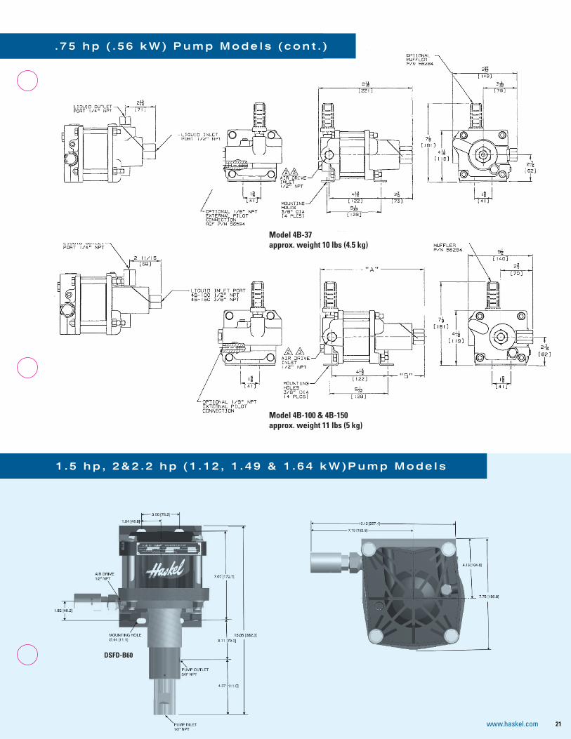
DSFD-B60
Model 4B-37approx. weight 10 lbs (4.5 kg)
Model 4B-100 & 4B-150approx. weight 11 lbs (5 kg)
. 7 5 h p ( . 5 6 k W ) P u m p M o d e l s ( c o n t . )
1 . 5 h p , 2 & 2 . 2 h p ( 1 . 1 2 , 1 . 4 9 & 1 . 6 4 k W ) P u m p M o d e l s
21www.haskel.com

1.5 and 2 hp low ratio pumps; -B10 and -B15 ratios
1.5 and 2 hp medium ratio pumps; -52, -72, -122, -202 and -302 ratios
1⁄2” NPT (-52, -72, 122)Liquid Outlet1⁄4 HP port (-202, -302)
25.4 mm = 1 inch
Breathers
24 mm241 mm
394 mm
ir Drive Inlet1 T
aust1 T
quid InletT
quid Outlet3 t
2 hp high ratio pumps; -683 and -903 ratios
1 . 5 h p , 2 & 2 . 2 h p ( 1 . 1 2 , 1 . 4 9 & 1 . 6 4 k W ) P u m p M o d e l s ( c o n t . )
ATV-4 pumps; double acting, high output-4, add distance piece dimension from page 11.
Interconnecting inlet and outlet port tubing shown.
DSTV-1.5 pump; single acting, high output
2 hp (1.49 & 1.64 kW) pump models; -1373 ratio
22 www.haskel.com

23www.haskel.comwww
ASFD-25 ASFD-35, ASFD-60ASFD-100ASFD-150
3⁄8" med. pressure}
ASFD-10
OUTLET PORT1/2” NPT
MountingBracket (2 places)
Handle
Air DriveExhaust Port1/2” NPT
Air Drive Inlet Port1/2” NPT
Hydraulic Outlet Port1/2” NPT(2 places, this side)
Hydraulic Inlet Port1/2” NPT(2 places, this side)
11 mm(7/16”) (TYP)
76 mm(3”)
279 mm(11”)
413 mm(15 1/4”)
154 mm(6 1/16”)17 mm
(11/16”)
144 mm(5 11/16”)
209 mm(8 1/4”)
102 mm(4”)
105 mm(4 5/32”) (TYP)
64 mm(2 1/2”)
(9 7/8”)119 mm
(4 11/16”)
ATV-8 pumps
MODEL OUTLET PORT INLET PORT
ASFD-25
1/2” NPT
1/2” NPT
ASFD-35
ASFD-60
ASFD-100 3/8” MEDIUM PRESSURE
9/16-18 THREADASFD-150
1.5 and 2 hp medium and high ratios; -25 through -150, -151*, -225*, -300* and -450* ratios*1⁄4” Super Pressure Outlet Port
1⁄2” NPT Liquid Outlet*
AFD or ASFD, -B60, -B100 pumps; double acting, high output
3 h p ( 2 . 2 4 k W ) P u m p M o d e l s
ASFD-15
ASFD-202
AIR DRIVE INLET PORT1/2” NPT
OUTLET PORT1/2” NPT
OUTLET PORT1/2” NPT
www.haskel.com
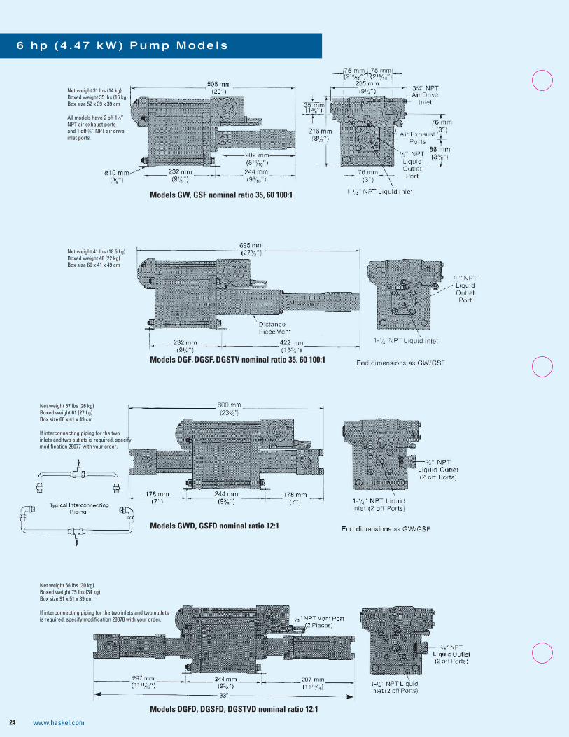
11⁄4”
and 1 off 3⁄4inlet ports.
Models GW, GSF nominal ratio 35, 60 100:1
Models DGF, DGSF, DGSTV nominal ratio 35, 60 100:1
If interconnecting piping for the two inlets and two outlets is required, specify modifi r.
Models GWD, GSFD nominal ratio 12:1
If interconnecting piping for the two inlets and two outlets is required, specify modifi r.
Models DGFD, DGSFD, DGSTVD nominal ratio 12:1
24 www.haskel.com

2X LIQUID INLET PORT 3/8" HIGH PRESSURE (25,000 PSIG MAX)
2X LIQUID OUTLET PORT 3/8" HIGH PRESSURE (25,000 PSIG MAX)
11.36[288 mm]
5.78[147 mm]
22.93[582 mm]
27.66[703 mm]
4.88[124 mm]
10.17[258 mm]
10.96[278 mm]
7.00[178 mm]
8.25[210 mm]
4X MOUNTING HOLES n 9/16"
CYCLING SPOOL ACCESS
AIR DRIVE INLETPORT 3/4" NPT(130 PSIG MAX)
2X AIR DRIVE/SEAL SECTION VENT PORT 1/4" NPT
9.65[245 mm]
5.21[132 mm]
Models 8HSFD-25, 8FD-25, 8SFD-25Inlet, Outlet ports 3/8’’ HP
Models 8DSFD-25 & 8DSTVD-25
Model 8SFD-40
Model 8SFD-65
25www.haskel.com
8 h p ( 5 . 9 7 k W ) P u m p M o d e l s

29.92 in [760 mm]
19.55 in [496 mm]
11.10 in [282 mm]
9.65 in [245 mm]
8.25 in [210 mm]26.48 in [673 mm]
4.88 in [124 mm]
32.73 in [831 mm]
2X HYDRAULIC OUTLET1" NPT PORT
2X HYDRAULIC INLET1 1/4" NPT PORT
4.25 in [108 mm]
7.00 in [178 mm]
18.11 in [460 mm]
�X8 ]mm31[ni35.(MOUNTING HOLES
AIR DRIVE INLET3/4 NPT
10.17 in [258 mm]
Model 8SFD2-55
www.haskel.com
Model 8SFD2-88
33.80 in [858 mm]
28.62 in [727 mm]
32.06 in [814 mm]
19.55 in [496 mm]
4.88 in [124 mm]
2X HYDRAULIC OUTLET1" NPT PORT
18.11 in [460 mm]
�X8 ]mm31[ni35.(MOUNTING HOLES)
26
11.10 in [282
8.25 in [210 mm]
9.65 in [245 mm]
2X HYDRAULIC INLET1 1/4" NPT PORT
4.25 in [108 mm]
7.00 in [178 mm]
10.17 in [258 mm]
AIR DRIVE LET3/4 NPT

Model D14STD-125
Model D14STD-315
HYDRAULIC OUTLET3/8 HP PORT
(MAWP: 29,000 PSI)
HYDRAULIC INTLET1/2 NPT PORT
(MAWP: 10,000 PSI)
HYDRAULIC OUTLET3/8 HP PORT(MAWP: 29,000 PSI)
HYDRAULIC INLET1/2 NPT PORT(MAWP: 10,000 PSI)
37.78 in [960 mm]
35.78 in [909 mm]
19.55 in [496 mm]
4.88 in [124 mm]
18.11 in [460 mm]
�X8 ]mm31[ni35.(MOUNTING HOLES)
Model 8SFD2-224
AIR DRIVE INLET3/4 NPT
11.10 in [282 mm]
8.25 in [210 mm]
9.65 in [245 mm]
4.25 in [108 mm]
7.00 in [178 mm]
10.17 in [258 mm]
1 0 h p ( 7 . 4 6 k W ) P u m p M o d e l s
27www.haskel.com

haskel.com [email protected]
For more information on our high-pressure products, visit Haskel.com or contact your local Haskel representative. Haskel is a brand of Accudyne Industries, a leading global provider of precision-engineered, process-critical and technologically advanced flow control systems and industrial compressors that deliver consistently high performance and give confidence to the mission of our customers in the most important industries and harshest environments around the world. The company is powered by more than 3,000 employees at 18 manufacturing facilities, supporting a broad range of industries in more than 150 countries.
hahah ksksk lelel c.commmm ommmcccomomoll c.cosales@haaskskelel mmcoml.ccookel.c.cskelel