harmonic interaction in high populations of distributed ...ieee-ecce.org/2014/images/documents/ss3b...
TRANSCRIPT
Harmonic Interaction in High Populations of Distributed Power
Resources
Johan H Enslin
Director, Energy Production & Infrastructure Center (EPIC)
Duke Energy Distinguished Chaired Professor
UNC Charlotte, NC, USA
[email protected]; http://epic.uncc.edu

Outline
• Interconnection of DER at Dense Populations
• Mechanism of System Resonance with DER
• Analysis with High Density PV Inverters
• Advanced DER Converter Controls
• Harmonic Mitigation of Smart Inverters
• Real-time HiL Testbed for Harmonic Evaluation
• Conclusions and Recommendations

Interconnection of DER at Dense Populations
Ouddorp, The Netherlands
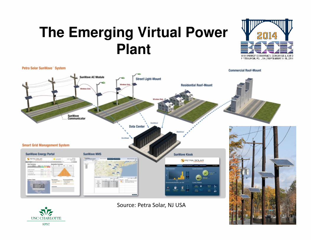
The Emerging Virtual Power Plant
Source: Petra Solar, NJ USA

Interconnection Issues
• Voltage Regulation and Flicker:
– May exceeding voltage limits and inverters trip
– Voltage fluctuations and flicker due to intermittency
• Harmonics:
– Inverters individually satisfy PQ standards
– PQ standards can temporarily be exceeded.
– Inverters trip unexpectedly
• Attention Points on Standards and Interconnections
– Effect of background supply distortion
– Increased distortion due to a system resonance
– Micro-grids and weak networks
– Islanding times and algorithms
– Natural damping

Simple electrical network with one inverter.
Ub
Lb Rb
R C
IPV
Mechanisms of DER Inverter Interactions

Analysis of DER inverter resonance
Mechanism of Parallel and Series Resonance
IhRp
Cp Lp
Cs
Ls
Ih Rs
Cs
Ls
Ih Rs
0
Z
[ohm]
1000 1500 f [Hz]0
Z
[ohm]
1000 1500 f [Hz]
CLf r
π2
1=
• Small current harmonics from large population of DER
inverters excite parallel resonance in networks.
• Supply voltage harmonics increase with DER inverters
due to series resonance.
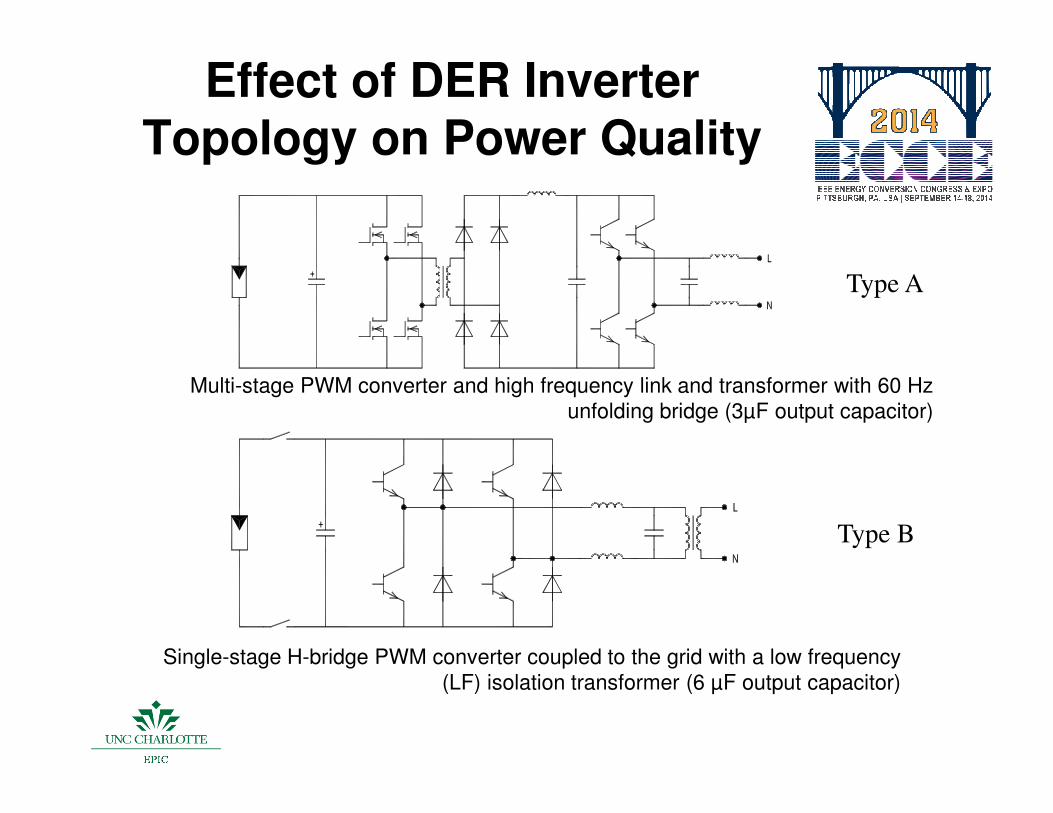
Single-stage H-bridge PWM converter coupled to the grid with a low frequency
(LF) isolation transformer (6 µF output capacitor)
Multi-stage PWM converter and high frequency link and transformer with 60 Hz
unfolding bridge (3µF output capacitor)
Effect of DER Inverter Topology on Power Quality
Type B
Type A

PV Inverter Test Installation
C-home
Spitzenberger 4-Q amplifier
L
N
+
-
Idc Udc Uac IacNorma D 6000 Uac Iac
Scope
Test object
(PV inverter)PV Simulator Network Simulator
L R
Net Impedance
Z=0
PersonalComputer
Waveform
Software
Power Analyser
PV Simulator 10 kW Network Simulator 10 kW
1 – 3 Parallel 1 kW Inverters

Current
Voltage
Sinus Supply: L = 1 mH R = 0,3 ΩΩΩΩ
Measurement ResultsHF Link Inverter – Type A
NL(3%) Supply: L = 1 mH R = 0,3 ΩΩΩΩ EN50160 (8%): L = 1 mH R = 0,3 ΩΩΩΩ
Current
Voltage
Current
Voltage
Voltage:- 200 V/div; Current:- 5 A/div
Time:- 4 ms/dive
C-home = 3 µF

Current
Voltage
Sinus Supply: L = 1 mH R = 0,3 ΩΩΩΩ NL(3%) Supply: L = 1 mH R = 0,3 ΩΩΩΩ EN50160 (8%): L = 1 mH R = 0,3 ΩΩΩΩ
Current
Voltage
Current
Voltage
Voltage:- 200 V/div; Current:- 5 A/div
Time:- 4 ms/dive
C-home = 3 µF
Measurement ResultsLF Link Inverter – Type B

System Analysis Configuration
50kV 10kV
2x36MVAZk=6%Load 18MW/19.1MVA
VP1
VP3
10kV/400V1x400kVAZk=4%
10kV/400V1x400kVAZk=4%50kV 10kV
2x18MVA1x36MVAZk=6%Load 40.6MW/43MVAFeedback 36MW
VP4
10kV/400V1x400kVAZk=4%
3x240Al, 11.62km
3x240Al, 5.9km
267m
net opening
WARMENHUIZEN
OUDDORP

Znet
Tr10kV/400
Vh3,5,...49
Vh1
+
-
+
-
Zkabel, 123m
Zh
Zh
Zh
Zh
Zh
ZhZl, 39m Zl,39m Zl, 39m
Zl, 32m Zl,33m Zl, 32m
Zh
Zh
Zl, 64m
Zkabel, 235m
Zh
ZhZl, 39m
Zh
Zh
Zh
ZhZl, 39m Zl, 54m
Zl, 34m Zl, 33m Zl, 33m
Zh
Zh
Zl, 54m
Zh
Zh
Zl, 21m
Zh
Zh
Zh
ZhZkabel,
65m
Zh
Zh
Zh
Zh
Zh
ZhZkabel,124m
P S
VAhf,IAhf
VAhm,IAhm
Zkabel,
5.9km
Vp,Ip
Vs,Is
Cinv*iPh*i
Jinv*i
A
V
Ch
Zh,appartement
Zh
Zh
Zh
Zh
Zh
Zh
Zh
Zh
2145A
2146
2147
Zkabel,20m
2145B
VAhe,IAhe
VBhf,IBhf
VBhm,IBhm VBhE,IBhE
Ph*i
A
V
Ch
Zl, 21m Zl, 21m Zl, 21m
Zl, 21m Zl, 21m Zl, 21m Zl, 21m
Network Simulation Model VP4

Simulation Results VP-4
Simulated waveforms at two locations for the VP4 network section with
average background distortion (Vmain – 2%)
Average Dutch (3%) Supply

15
Simulation Results VP-4
n Simulated waveforms at two locations for the VP4 network section with
maximum allowable distortion
Maximum EN50160 (8%) Supply Distortion

16
Harmonics VP4 average pollution
VP4 Voltage and Current Harmonics with Dutch Average Distortion
0%
1%
2%
3%
4%
3 5 7 9 11 13 15 17 19 21 23 25 27 29 31 33 35
Harmonic order
Ha
rmo
nic
Vo
ltag
e (
% V
1)
0%
2%
4%
6%
8%
10%
12%
Ha
rmo
nic
Cu
rren
ts (
% I
1)
V main Vs Tr V 2145 BhE Is Tr I 2145 BhE

Advanced Smart DER Converter Controls
Generator Emulation Controls (GEC)
• Control PV inverters in a manner that emulates characteristics and behavior of traditional synchronous generators
GEC allows PV inverters to:
• Supply reactive power
• Active Power Filtering
• Support voltage stability through Volt / VAr control
• Perform voltage ride-through (VRT)
• V-f regulation for Micro-grid operation

GEC Concept Overview
0 sins
o
s
V VP
X
δ⋅ ⋅=
0 (1 cos )s
o
s
V VQ
Xδ
⋅= −

GEC Multi-Mode Operation• Legacy Tie
– UL1741-compliant grid-tie operation
– Active Harmonic Filtering
• Smart Tie– Voltage Regulation support
– Programmable V-f windows
– Low-voltage ride-through
– Reactive power injection
– Ramping control and curtailment
– Active Harmonic Filtering
• Islanded - MicroGrid– Voltage and frequency regulation
– Automatic load sharing
– Black Start support
– Seamless transition to and from grid-tie
– Energy storage integration
– Active Harmonic Filtering
19

LVRT Operation
• GEC control is implemented into grid connected and micro-grid applications
• DER units stay connected through a low voltage transient and inject reactive power until voltage stabilize
• Units inject active power as soon as voltage is stable for a few cycles

Harmonic Mitigation with GEC-based Smart PV Inverter
Voltage THD at PCC is reduced from 9.2% to 4.3% by connecting the PV AC string with PQ mitigating algorithm
GEC Control structure of PQ mitigation algorithm

Duke Energy Smart Grid Lab
• Real Time Digital Simulator (RTDS) – 3 enhanced racks• 32 core OPAL-RT real-time power simulator• 90 kVA Ametek Grid Simulator and Amplifier• 150 A with 120V, 208V, 480V 1&3 phase power supplies• Amatek TerraSAS 10 kW PV SImulator• High speed fiber connections between labs and server room• Dedicated and secured private LAN for external data streams• Raised floor access for power, communication and control cables• 6 fast response large LCD Screens and image control• Data storage devices and SCADA gateways• Communications - Private HP Server for data analytics• HP X820, 16-Core, Dual Processor Xeon Workstation• Simulation tools including - PSS/E; ETAP; EMTP-RV; • RSCAD; PSCAD; Hypersim, RTLAB, etc.

Duke Energy Smart Grid Lab.
HP Dedicated Server for Data Analytics
DESG Control RoomRTDS and OPAL-RT
Simulators
Substation Relay Equipment
SEL; ABB, etc90 kVA Ametek Grid
Simulator & Amplifier
I/O Control
DC
Po
wer
AmetekTerraSAS PV
Simulator

Conclusions & Recommendations
• Small current harmonics from large population of DER inverters excite resonance in distribution networks.
• Background voltage harmonics increase with DER Inverters due to series resonance.
• Household and cable capacitance together with short-circuit inductance can be dominant in resonance circuit
• Smart Inverters, emulating synchronous machine characteristics, can mitigate power quality issues
• Evaluate and test inverters with real-time HiL Testbeds
• Need to develop guidelines and standards for weak, Micro-grid or islanded network operations with variable impedances.

References
• Enslin, JHR: “Integration of Photovoltaic Solar Power – The Quest towards Dispatchability”, IEEE Instrumentation & Measurement Magazine, pp. 21-26, April 2014.
• Campanhol, L.B.G; da Silva, S.A.O; Sampaio, L.P; Junior, A.A.O: “A grid-connected photovoltaic power system with active power injection, reactive power compensation and harmonic filtering”, Power Electronics Conference (COBEP), 2013 Brazilian, pp. 642 - 649, Oct. 2013.
• Lee, C-.T.; Chu, C-.C.; Cheng, P-.T., "A New Droop Control Method for the Autonomous Operation of Distributed Energy Resource Interface Converters," Power Electronics, IEEE Transactions on , vol.28, no.4, pp.1980,1993, April 2013.
• Alatrash, H; Mensah, A; Mark, E; Haddad, G; Enslin, JHR: “Generator Emulation Controls for Photovoltaic Inverters”, IEEE Transactions on Smart Grid, Special Issue: Application of Smart Grid Technologies on Power Distribution Systems, Vol. 3, No 2, pp. 996-1011, June 2012.
• Sun, J: “Power Quality in Renewable Energy Systems - Challenges and Opportunities”, International Conference on Renewable Energies and Power Quality (ICREPQ’12), Spain, 28-30 March 2012.
• Liserre, M.; Teodorescu, R.; Blaabjerg, F., "Stability of photovoltaic and wind turbine grid-connected inverters for a large set of grid impedance values," Power Electronics, IEEE Transactions on , vol.21, no.1, pp.263,272, Jan. 2006.
• Enslin, JHR; Heskes, PJM: “Harmonic interaction between a large number of distributed power inverters and the distribution network”, IEEE Transactions on Power Electronics, Vol. 19, No. 6, pp. 1586 - 1593, Nov. 2004.
25