hardware manual - new.e-yantra.org
TRANSCRIPT

Hardware Manual
for eYFi-Mega Development Board
Produced by: e-Yantra Team
https://e-yantra.org/products/eyfi-mega
Version: 0.1
Dated: December 14, 2019

About this DocumentThis document is created for all developers wanting to work with the eYFi-Mega
development board. It provides the detailed description and specification of the
board.
Revision HistoryFor revision history of this document, please refer to the Appendix A.
Disclaimer and Copyright NoticeInformation in this document, including URL references, is subject to change with-
out notice. This document is provided as is with no warranties whatsoever, includ-
ing any warranty or merchantability, non-infringement, fitness for any particular
purpose, or any warranty otherwise arising out of any proposal, specification or
sample. All liability, including liability for infringement of any proprietary rights,
relating to use of information in this document is disclaimed. No licenses express
or implied to any intellectual property rights are granted herein. The e-Yantra Prod-
ucts logo is a registered trademark.
Copyright ©2019 e-Yantra, ERTS Lab, CSE Dept., IIT Bombay, India.
1

Table of Contents
1 Board Overview 5
1.1 Kit Contents . . . . . . . . . . . . . . . . . . . . . . . . . . . . . . . . . 6
1.2 Quick Start . . . . . . . . . . . . . . . . . . . . . . . . . . . . . . . . . . 6
1.2.1 Getting Started . . . . . . . . . . . . . . . . . . . . . . . . . . . 6
1.2.2 System Requirements . . . . . . . . . . . . . . . . . . . . . . . 6
1.2.3 Development Toolchains . . . . . . . . . . . . . . . . . . . . . 6
1.3 Features . . . . . . . . . . . . . . . . . . . . . . . . . . . . . . . . . . . . 7
1.4 Specifications . . . . . . . . . . . . . . . . . . . . . . . . . . . . . . . . . 7
2 Hardware Description 8
2.1 Functional Description . . . . . . . . . . . . . . . . . . . . . . . . . . . 10
2.1.1 ATmega2560 micro-controller . . . . . . . . . . . . . . . . . . 10
2.1.2 ESP32 micro-controller . . . . . . . . . . . . . . . . . . . . . . 10
2.1.3 16 MHz crystal . . . . . . . . . . . . . . . . . . . . . . . . . . . 10
2.1.4 LEDs . . . . . . . . . . . . . . . . . . . . . . . . . . . . . . . . . 11
2.1.5 Switches . . . . . . . . . . . . . . . . . . . . . . . . . . . . . . . 12
2.1.6 ICSP connector . . . . . . . . . . . . . . . . . . . . . . . . . . . 13
2.1.7 GPIO1 header . . . . . . . . . . . . . . . . . . . . . . . . . . . . 13
2.1.8 GPIO2 header . . . . . . . . . . . . . . . . . . . . . . . . . . . . 15
2.1.9 INTx header . . . . . . . . . . . . . . . . . . . . . . . . . . . . . 15
2.1.10 ADCx header . . . . . . . . . . . . . . . . . . . . . . . . . . . . 15
2.1.11 I2C header . . . . . . . . . . . . . . . . . . . . . . . . . . . . . . 15
2.1.12 UART header . . . . . . . . . . . . . . . . . . . . . . . . . . . . 15
2.1.13 SPI header . . . . . . . . . . . . . . . . . . . . . . . . . . . . . . 16
2.1.14 PWM header . . . . . . . . . . . . . . . . . . . . . . . . . . . . . 16
2.1.15 ESP32 GPIO header . . . . . . . . . . . . . . . . . . . . . . . . . 16
2.1.16 Micro-USB connector . . . . . . . . . . . . . . . . . . . . . . . 17
3 Power Management 19
3.1 5V DC Supply . . . . . . . . . . . . . . . . . . . . . . . . . . . . . . . . . 19
3.2 3.3V header . . . . . . . . . . . . . . . . . . . . . . . . . . . . . . . . . . 19
3.3 EXT_PWR header . . . . . . . . . . . . . . . . . . . . . . . . . . . . . . 19
4 References 20
Appendices 21
A Revision History 21
B Flashing Boot-loader on ATmega2560 22
2
C Flashing Boot-loader on ESP32 25
3

List of Figures
1 eYFi-Mega development board . . . . . . . . . . . . . . . . . . . . . . 5
2 Block diagram of eYFi-Mega . . . . . . . . . . . . . . . . . . . . . . . . 8
3 Functional diagram of eYFi-Mega . . . . . . . . . . . . . . . . . . . . . 9
4 eYFi-Mega Pinout Diagram for ATmega2560 . . . . . . . . . . . . . . . 14
5 eYFi-Mega Pinout Diagram for ESP32 . . . . . . . . . . . . . . . . . . 18
6 Device Programming dialog box in Atmel Studio 7 . . . . . . . . . . . 23
7 Fuse settings to be done . . . . . . . . . . . . . . . . . . . . . . . . . . 23
8 All OK message after programming the Fuses . . . . . . . . . . . . . . 24
List of Tables
1 Specifications of eYFi-Mega development board . . . . . . . . . . . . 7
2 Functional Diagram of eYFi-Mega . . . . . . . . . . . . . . . . . . . . . 9
3 Partition Table of on-board ESP32 micro-controller . . . . . . . . . . 10
4 Patterns of Wi-Fi status LED with various states of the board . . . . . 11
5 Function of Switches S1, S2 and S3 . . . . . . . . . . . . . . . . . . . . 13
6 Switch positions for various programming modes . . . . . . . . . . . 13
7 Revision History of the document . . . . . . . . . . . . . . . . . . . . . 21
4

1Board Overview
Figure 1: eYFi-Mega development board
The eYFi-Mega board provides an flexible and affordable way for users to try out new
concepts and build prototype projects with the 8-bit ATmega2560 micro-controller in
TQFP100 package and the 32-bit ESP32 micro-controller, choosing from the various
combinations of performance, power consumption and features.
The eYFi-Mega board does not require any specialized hardware for programming as it
comes with pre-installed bootloader file thus, the firmware on ATmega2560 and ESP32
can be easily updated either wired / wirelessly (Over-The-Air).
The eYFi-Mega board comes with the comprehensive support of Arduino Programming
Language and Espressif IoT Development Framework (esp-idf) which is the official de-
velopment framework for the ESP32 chip.
5

The eYFi-Mega board comes with the pre-defined group of pins having the same func-
tionality, making it easier for the developer to access and work with it.
1.1 Kit Contents
The eYFi-Mega Kit contains the following items:
• eYFi-Mega Development Board
• Interface Board
• USB micro-B plug to USB-A plug cable
1.2 Quick Start
For more information on the eYFi-Mega board and to access the documentation and
tutorials, visit https://e-yantra.org/products/eyfi-mega.
1.2.1 Getting Started
Follow the sequence below to configure the eYFi-Mega and launch the demo software:
• Connect the eYFi-Mega board to a PC with a USB micro-B plug to USB-A plug
cable through USB connector to power the board. The red LEDs AVR_ON and
ESP_ON should light up.
• The RGB LED should light up and blink Red, Green and Blue colors in a sequence
at the intervals of a second.
• Press button USER_SW (User Switch).
• Observe the change in colors on the RGB LED, by pressing the button USER_SW. It
will glow the colors Yellow, Cyan, Magenta, Red, Green, Blue in a sequence. After
this, the RGB LED will reset to the blinking of Red, Green and Blue color in the
interval of a second.
1.2.2 System Requirements
• Linux: Ubuntu LTS 16.04 and 18.04
• USB micro-B plug to USB-A plug cable
1.2.3 Development Toolchains
• eY-IDE (Visual Studio Code extension)
• AVR-GCC
• ESP-IDF
6

1.3 Features
Your eYFi-Mega development board includes the following features:
• Dual Micro-controller Board 8-bit ATmega2560 & 32-bit ESP32
• High Output Power 12.5 W (5V, 2.5A)
• Wi-Fi Protocol: 802.11 b/g/n (802.11n up to 150 Mbps),
Frequency Range: 2.4 GHz 2.5 GHz
• Bluetooth Low Energy Protocol: Bluetooth v4.2 BR/EDR and
BLE specification
• On-board File Storage 700 KB SPI-Flash File System (expandable up
to 3 MB)
• Compatible with FreeRTOS Both micro-controllers are capable of running
FreeRTOS, ESP32 runs FreeRTOS out-of-the-
box
• Arduino Programming Language Both micro-controllers can be programmed
using Arduino Programming Language
1.4 Specifications
Table 1 summarizes the specifications of the eYFi-Mega board.
Table 1: Specifications of eYFi-Mega development board
Parameter Value
Board Supply Voltage 4.75 VDC to 5.25 VDC from USB Micro-B cable (connected to a PC)
7.0 VDC to 21.0 VDC from External Power Supply
Dimensions 107.95 mm x 64.01 mm x 24 mm (L x W x H)
Break-out power output 3.3 VDC (800 mA max)
5.0 VDC (2.5 A max)
RoHS status Compliant
7

2Hardware Description
Figure 2: Block diagram of eYFi-Mega
The eYFi-Mega board includes ATmega2560 and ESP32 micro-controllers and a range
of useful peripheral features (as the block diagram in Figure 2). This chapter describes
how these peripherals operate and interface to the micro-controller.
8

Figure 3: Functional diagram of eYFi-Mega
Table 2-1 summarizes the parts of the eYFi-Mega board with respect to the Figure 3.
Table 2: Functional Diagram of eYFi-Mega
# Component Name # Component Name
1 ATmega2560 micro-controller 14 PWM header
2 INTx header 15 EXT_PWR header
3 ADCx header 16 S3 switch
4 I2C header 17 3.3 V header
5 GPIO1 header 18 S1 switch
6 USER_SW push button 19 TX LED and RX LED
7 16 MHz crystal 20 ESP32 GPIO header
8 AVR_RESET push button 21 S2 switch
9 GPIO2 header 22 Micro-USB connector
10 UART header 23 Wi-Fi Status LED
11 AVR_ON LED 24 ESP_ON LED
12 ICSP connector 25 ESP32 micro-controller
13 SPI header 26 ESP_RESET push button
9

2.1 Functional Description
2.1.1 ATmega2560 micro-controller
ATmega2560 micro-controller is one of the most rich feature AVR micro-controller from
Atmel featuring 256K Flash, 8K RAM, 86 I/O lines, 16 ADCs, 4 UARTs, 6 Timers, 8 Inter-
rupts and much more.
All AVR micro-controllers can be programmed using ICSP, external programmer or boot-
loader. Advantage with the boot-loader is that you don’t need any external hardware
to load the .hex file on the micro-controller. If Boot-loader firmware is loaded on the
micro-controller then it can be programmed directly via serial port of USB using PC.
We have already loaded the boot-loader firmware on ATmega2560 micro-controller. It
is recommended that you always update the firmware on ATmega2560 either through
wired via Micro-USB port or wirelessly i.e. Over-The-Air (OTA). For more information
on how to update the firmware OTA, refer the Section Button - Wireless Flash in the
Software Manual of eYFi-Mega development board.
2.1.2 ESP32 micro-controller
ESP32-WROOM-32 is a powerful, generic Wi-Fi+BT+BLE MCU module that targets a
wide variety of applications, ranging from low-power sensor networks to the most de-
manding tasks, such as voice encoding, music streaming and MP3 decoding.
It has integrated SPI flash of 4 MB. We have partitioned this memory of on-board ESP32
to accommodate 1 MB OTA (Over-The-Air) application, 2 MB User application and 700
KB File Storage. This partition table can be modified by you as per your requirement.
For example, if you want to increase or decrease the size of the 700 KB File Storage
you can update the partition table. If you decide to modify the partition table for your
project, you might not be able to use the OTA App because our OTA App is compatible
with the partition table described below (Refer Table 3). In case you accidentally erase
the partition you can download our Partition Table and our OTA App from our website.
The current partition table is described below:
Table 3: Partition Table of on-board ESP32 micro-controller
Partition Name Start Address Size
reserved area (nvs, otadata, phy_init) – 300 KB
factory (ota-app) 0x10000 1 MB
app1 (user-app) 0x110000 2 MB
storage (spiffs) 0x310000 700 KB
2.1.3 16 MHz crystal
The frequency of crystal connected to ATmega2560 is 16 MHz.
10
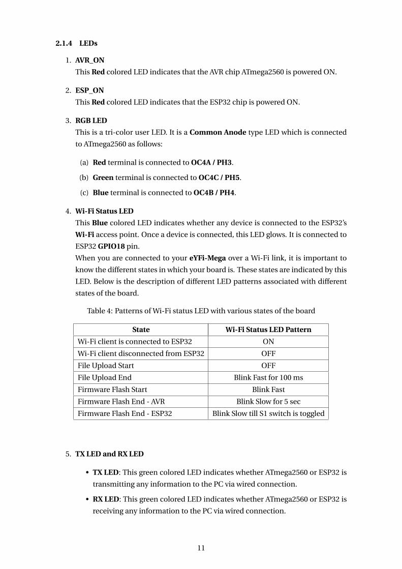
2.1.4 LEDs
1. AVR_ON
This Red colored LED indicates that the AVR chip ATmega2560 is powered ON.
2. ESP_ON
This Red colored LED indicates that the ESP32 chip is powered ON.
3. RGB LED
This is a tri-color user LED. It is a Common Anode type LED which is connected
to ATmega2560 as follows:
(a) Red terminal is connected to OC4A / PH3.
(b) Green terminal is connected to OC4C / PH5.
(c) Blue terminal is connected to OC4B / PH4.
4. Wi-Fi Status LED
This Blue colored LED indicates whether any device is connected to the ESP32’s
Wi-Fi access point. Once a device is connected, this LED glows. It is connected to
ESP32 GPIO18 pin.
When you are connected to your eYFi-Mega over a Wi-Fi link, it is important to
know the different states in which your board is. These states are indicated by this
LED. Below is the description of different LED patterns associated with different
states of the board.
Table 4: Patterns of Wi-Fi status LED with various states of the board
State Wi-Fi Status LED Pattern
Wi-Fi client is connected to ESP32 ON
Wi-Fi client disconnected from ESP32 OFF
File Upload Start OFF
File Upload End Blink Fast for 100 ms
Firmware Flash Start Blink Fast
Firmware Flash End - AVR Blink Slow for 5 sec
Firmware Flash End - ESP32 Blink Slow till S1 switch is toggled
5. TX LED and RX LED
• TX LED: This green colored LED indicates whether ATmega2560 or ESP32 is
transmitting any information to the PC via wired connection.
• RX LED: This green colored LED indicates whether ATmega2560 or ESP32 is
receiving any information to the PC via wired connection.
11

2.1.5 Switches
1. AVR_RESET
This push button is used to reset the AVR chip ATmega2560 micro-controller.
2. ESP_RESET
This push button is used to reset the ESP32 micro-controller.
3. USER_SW
This push button is a User Switch. It is connected to PE7 / INT7 pin of ATmega2560.
4. S1
This switch is used to decide which application code ESP32 should be running.
If S1 is switched to the left side (indicated with a Wi-Fi symbol), ESP32 will run
the Over-The-Air (OTA) application. This application turns ON the ESP32 Wi-Fi
Access Point, listens and waits for any client to get connected with itself. It is
also used for flashing the firmware for ATmega2560 and ESP32 wirelessly. If S1
is switched to right side, ESP32 will run the User application (which is flashed on
ESP32 either via wired connection or wirelessly).
5. S2
This switch is used to make or break the connection between ATmega2560 and
ESP32. If S2 is switched to left side (indicated with a Wi-Fi symbol), the UART0
TX, RX lines of ATmega2560 gets connected to the UART1 RX, TX lines of ESP32
respectively. Through this connection, one can send and receive any data between
ATmega2560 and ESP32. If S2 is switched to right side, the connection between
ATmega2560 and ESP32 breaks.
Note: Make sure that while flashing the firmware for ATmega2560 wirelessly, the
S2 switch is on the left side.
6. S3
This switch is used to decide whether to flash firmware on ATmega2560 or ESP32
through wired connection. If S3 is switched to left side (indicated with W_AVR),
one can flash firmware to ATmega2560 and if it is switched to right side (indicated
with W_ESP/Wi-Fi symbol), one can flash firmware to ESP32 through wired con-
nection. One can also use this switch for debugging purposes by printing data on
the Wired Serial Monitor. For more information on Wired Serial Monitor, refer to
the Section Button - Wired Serial Monitor in the Software Manual of eYFi-Mega
development board.
Note: Make sure that while flashing the firmware for ATmega2560 wirelessly, the
S3 switch is on the right side.
Table 5 highlights the function of Switches S1, S2 and S3 in short.
Table 6 summarizes the use of the Switches S1, S2 and S3 and their positions for flashing
the firmware on ATmega2560 and ESP32 via wired connection or wirelessly (OTA).
12
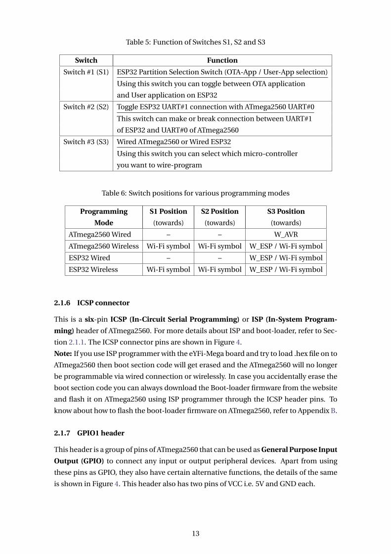
Table 5: Function of Switches S1, S2 and S3
Switch Function
Switch #1 (S1) ESP32 Partition Selection Switch (OTA-App / User-App selection)
Using this switch you can toggle between OTA application
and User application on ESP32
Switch #2 (S2) Toggle ESP32 UART#1 connection with ATmega2560 UART#0
This switch can make or break connection between UART#1
of ESP32 and UART#0 of ATmega2560
Switch #3 (S3) Wired ATmega2560 or Wired ESP32
Using this switch you can select which micro-controller
you want to wire-program
Table 6: Switch positions for various programming modes
Programming S1 Position S2 Position S3 Position
Mode (towards) (towards) (towards)
ATmega2560 Wired – – W_AVR
ATmega2560 Wireless Wi-Fi symbol Wi-Fi symbol W_ESP / Wi-Fi symbol
ESP32 Wired – – W_ESP / Wi-Fi symbol
ESP32 Wireless Wi-Fi symbol Wi-Fi symbol W_ESP / Wi-Fi symbol
2.1.6 ICSP connector
This is a six-pin ICSP (In-Circuit Serial Programming) or ISP (In-System Program-
ming) header of ATmega2560. For more details about ISP and boot-loader, refer to Sec-
tion 2.1.1. The ICSP connector pins are shown in Figure 4.
Note: If you use ISP programmer with the eYFi-Mega board and try to load .hex file on to
ATmega2560 then boot section code will get erased and the ATmega2560 will no longer
be programmable via wired connection or wirelessly. In case you accidentally erase the
boot section code you can always download the Boot-loader firmware from the website
and flash it on ATmega2560 using ISP programmer through the ICSP header pins. To
know about how to flash the boot-loader firmware on ATmega2560, refer to Appendix B.
2.1.7 GPIO1 header
This header is a group of pins of ATmega2560 that can be used as General Purpose Input
Output (GPIO) to connect any input or output peripheral devices. Apart from using
these pins as GPIO, they also have certain alternative functions, the details of the same
is shown in Figure 4. This header also has two pins of VCC i.e. 5V and GND each.
13

Fig
ure
4:eY
Fi-
Meg
aP
ino
utD
iagr
amfo
rAT
meg
a256
0
14

2.1.8 GPIO2 header
This is another header which is also a group of pins of ATmega2560 that can be used as
General Purpose Input Output (GPIO) to connect any input or output peripheral de-
vices. Apart from using these pins as GPIO, they also have certain alternative functions,
the details of the same is shown in Figure 4. This header also has two pins of VCC i.e. 5V
and GND each.
2.1.9 INTx header
This header is a group of pins of ATmega2560 that can be used as External Hardware
Interrupt (INT) sources. There are eight External Interrupt sources from INT7 to INT0
in ATmega2560. The Interrupt sources INT7:4 are present on this header. The other
four Interrupt sources INT3:0 are also available on the board but are not present on
this header, since they have other alternate functions which are given more priority.
These pins INT3:0 can be found in Figure 4. The x in the header name INTx stands for
Interrupt source number and ranges from 7 to 4 for this board. Apart from using these
pins as External Interrupts, they also have certain alternative functions, the details of
the same is shown in Figure 4. This header also has two pins of VCC i.e. 5V and GND
each.
2.1.10 ADCx header
This header is a group of pins of ATmega2560 that can be used as analog inputs or chan-
nels for the Analog to Digital Converter (ADC) inside the micro-controller. There are
sixteen ADC channels from ADC15 to ADC0 in ATmega2560. All ADC channels are
present on this header. The x in the header name ADCx stands for ADC channel and
ranges from 16 to 0. Apart from using these pins as ADC channels, they also have cer-
tain alternative functions, the details of the same is shown in Figure 4. This header also
has two pins of VCC i.e. 5V and GND each.
2.1.11 I2C header
This header is a group of pins of ATmega2560 that can be used as 2-wire Serial Inter-
face Data and Clock for Inter-Integrated Circuit (I2C or I2C) protocol in the micro-
controller. The SDA or PD1 are two names of the same pin of micro-controller. Simi-
larly, SCL or PD0 are two names of the same pin of micro-controller. Apart from using
these pins as I2C serial data and clock, they also have certain alternative functions, the
details of the same is shown in Figure 4. This header also has two pins of VCC i.e. 5V and
GND each.
2.1.12 UART header
This header is a group of pins of ATmega2560 that can be used as Transmit (TX) and
Receive (RX) Data pins for Universal Asynchronous Receiver and Transmitter (UART)
15
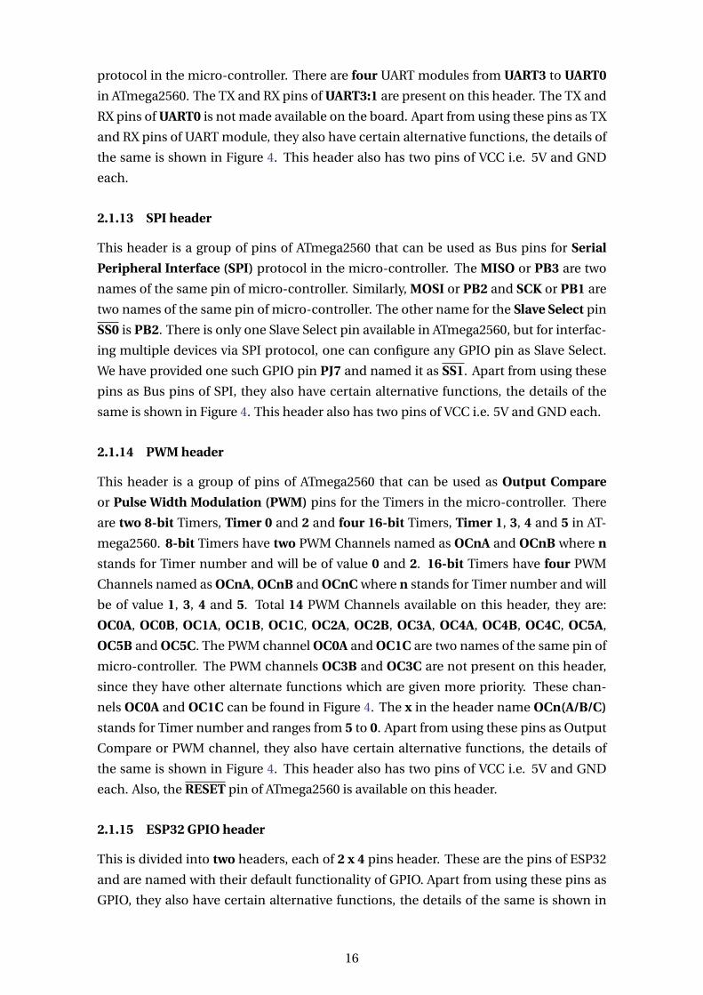
protocol in the micro-controller. There are four UART modules from UART3 to UART0
in ATmega2560. The TX and RX pins of UART3:1 are present on this header. The TX and
RX pins of UART0 is not made available on the board. Apart from using these pins as TX
and RX pins of UART module, they also have certain alternative functions, the details of
the same is shown in Figure 4. This header also has two pins of VCC i.e. 5V and GND
each.
2.1.13 SPI header
This header is a group of pins of ATmega2560 that can be used as Bus pins for Serial
Peripheral Interface (SPI) protocol in the micro-controller. The MISO or PB3 are two
names of the same pin of micro-controller. Similarly, MOSI or PB2 and SCK or PB1 are
two names of the same pin of micro-controller. The other name for the Slave Select pin
SS0 is PB2. There is only one Slave Select pin available in ATmega2560, but for interfac-
ing multiple devices via SPI protocol, one can configure any GPIO pin as Slave Select.
We have provided one such GPIO pin PJ7 and named it as SS1. Apart from using these
pins as Bus pins of SPI, they also have certain alternative functions, the details of the
same is shown in Figure 4. This header also has two pins of VCC i.e. 5V and GND each.
2.1.14 PWM header
This header is a group of pins of ATmega2560 that can be used as Output Compare
or Pulse Width Modulation (PWM) pins for the Timers in the micro-controller. There
are two 8-bit Timers, Timer 0 and 2 and four 16-bit Timers, Timer 1, 3, 4 and 5 in AT-
mega2560. 8-bit Timers have two PWM Channels named as OCnA and OCnB where n
stands for Timer number and will be of value 0 and 2. 16-bit Timers have four PWM
Channels named as OCnA, OCnB and OCnC where n stands for Timer number and will
be of value 1, 3, 4 and 5. Total 14 PWM Channels available on this header, they are:
OC0A, OC0B, OC1A, OC1B, OC1C, OC2A, OC2B, OC3A, OC4A, OC4B, OC4C, OC5A,
OC5B and OC5C. The PWM channel OC0A and OC1C are two names of the same pin of
micro-controller. The PWM channels OC3B and OC3C are not present on this header,
since they have other alternate functions which are given more priority. These chan-
nels OC0A and OC1C can be found in Figure 4. The x in the header name OCn(A/B/C)
stands for Timer number and ranges from 5 to 0. Apart from using these pins as Output
Compare or PWM channel, they also have certain alternative functions, the details of
the same is shown in Figure 4. This header also has two pins of VCC i.e. 5V and GND
each. Also, the RESET pin of ATmega2560 is available on this header.
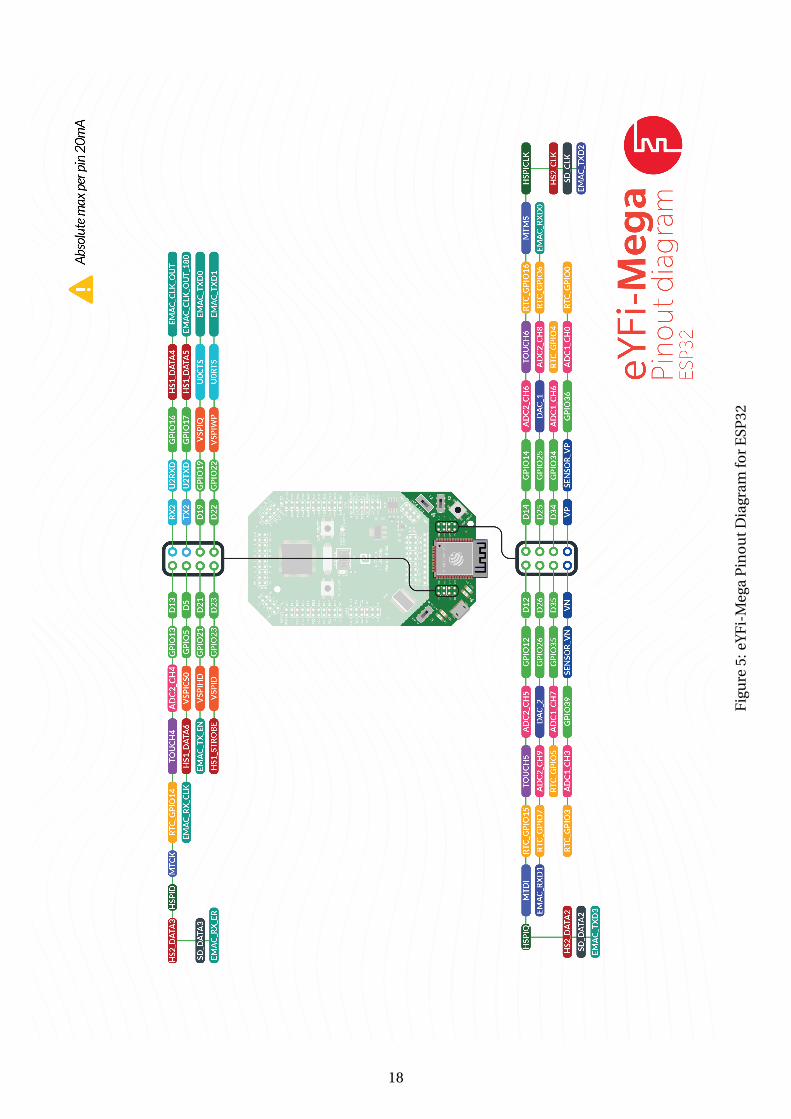
2.1.15 ESP32 GPIO header
This is divided into two headers, each of 2 x 4 pins header. These are the pins of ESP32
and are named with their default functionality of GPIO. Apart from using these pins as
GPIO, they also have certain alternative functions, the details of the same is shown in
16
Figure 5. This header also has Transmit (TX) and Receive (RX) Data pins of UART2 of
ESP32.
2.1.16 Micro-USB connector
This is a Micro-USB port where a USB micro-B plug to USB-A plug cable can be con-
nected to the PC. It can be used to flash the firmware on ATmega2560 or ESP32 via wired
connection. Also, one can connect the board to PC via this connector for the debugging
purposes by printing data on the Wired Serial Monitor.
17
Fig
ure
5:eY
Fi-
Meg
aP
ino
utD
iagr
amfo
rE
SP32
18

3Power Management
3.1 5V DC Supply
There are multiple 5VDC supply available on the board, which one can use to power
multiple devices easily and there will be no need to divide the supply further.
3.2 3.3V header
This header is a group of pins that provide 3.3VDC supply. Maximum of 800 mA current
can be drawn from these pins, but if high current is drawn from these pins, it will also
affect the power delivered to ESP32 and will reduce its Wi-Fi signal strength.
3.3 EXT_PWR header
This header is a group of pins where the eYFi-Mega board can be powered by an External
DC Supply. These pins are divide into VIN and GND each having four pins. The positive
terminal of External DC Supply should be connected to any of the four VIN pins and the
negative terminal should be connected to any of the four GND pins. The External DC
Supply Voltage should strictly be within the range 7.0 VDC to 21.0 VDC.
When the board is powered from External DC Supply, typically 1A and maximum 2.5A
current can be drawn from the 5V pins. But if current more than 1.5A is drawn from the
5V pins, one has to use cooling mechanism as the board will become hot on drawing
larger currents.
19

4References
In addition to this document, the following references will be helpful:
1. ATmega2560 datasheet, available at https://ww1.microchip.com/downloads/en/devicedoc/atmel-2549-8-bit-avr-microcontroller-atmega640-1280-1281-2560-2561_datasheet.pdf
2. ESP32-WROOM32 datasheet, available at https://www.espressif.com/sites/default/files/documentation/esp32-wroom-32_datasheet_en.pdf
3. Espressif IoT Development Framework (ESP-IDF) Programming Guide, available
at https://docs.espressif.com/projects/esp-idf/en/stable/index.html
4. I2C Protocol explained
(a) by Sparkfun: https://learn.sparkfun.com/tutorials/i2c
(b) by Texas Instruments (TI) http://www.ti.com/lit/an/slva704/slva704.pdf
5. SPI Protocol explained
(a) by Sparkfun: https://learn.sparkfun.com/tutorials/serial-peripheral-interface-spi
(b) by electroSome https://electrosome.com/spi/
20

Appendices ARevision History
Table 7: Revision History of the document
Date Version Release notes
December 14, 2019 v0.1 First release of the document
21

BFlashing Boot-loader on ATmega2560
Note: Refer to this section only if you have accidentally overwritten the Boot-loader
firmware of ATmega2560 on eYFi-Mega board.
Follow each of the steps given below carefully:
1. Components and Software required to get started:
(a) eYFi-Mega board
(b) USB micro-B plug to USB-A plug cable
(c) USB A-Male to B-Male cable
(d) Atmel AVRISP mkII (for more details, refer to link)
(e) Atmel Studio 7 software (only on Windows platform)
(f) Boot-loader firmware of ATmega2560 micro-controller on eYFi-Mega board
(can be downloaded from Downloads section on eYFi-Mega page, link: https://e-yantra.org/products/eyfi-mega).
2. Connect the USB A-Male to B-Male cable to the PC and Atmel AVRISP mkII.
3. Connect the 6-pin AVR ISP FRC cable of Atmel AVRISP mkII to the ICSP header on
eYFi-Mega board.
Note: The notch on the FRC cable should match with the notch provided around
the ICSP header.
4. Connect the USB micro-B plug to USB-A plug cable to the PC and Micro-USB con-
nector on eYFi-Mega board.
5. Once the above connections are done, check the LED status on Atmel AVRISP
mkII. If the LED color is Green, this means that everything is working fine and
you can proceed with the next step. But, if the LED color is Orange or Red, this
means that the connections between the Atmel AVRISP mkII and eYFi-Mega board
is weak.
22
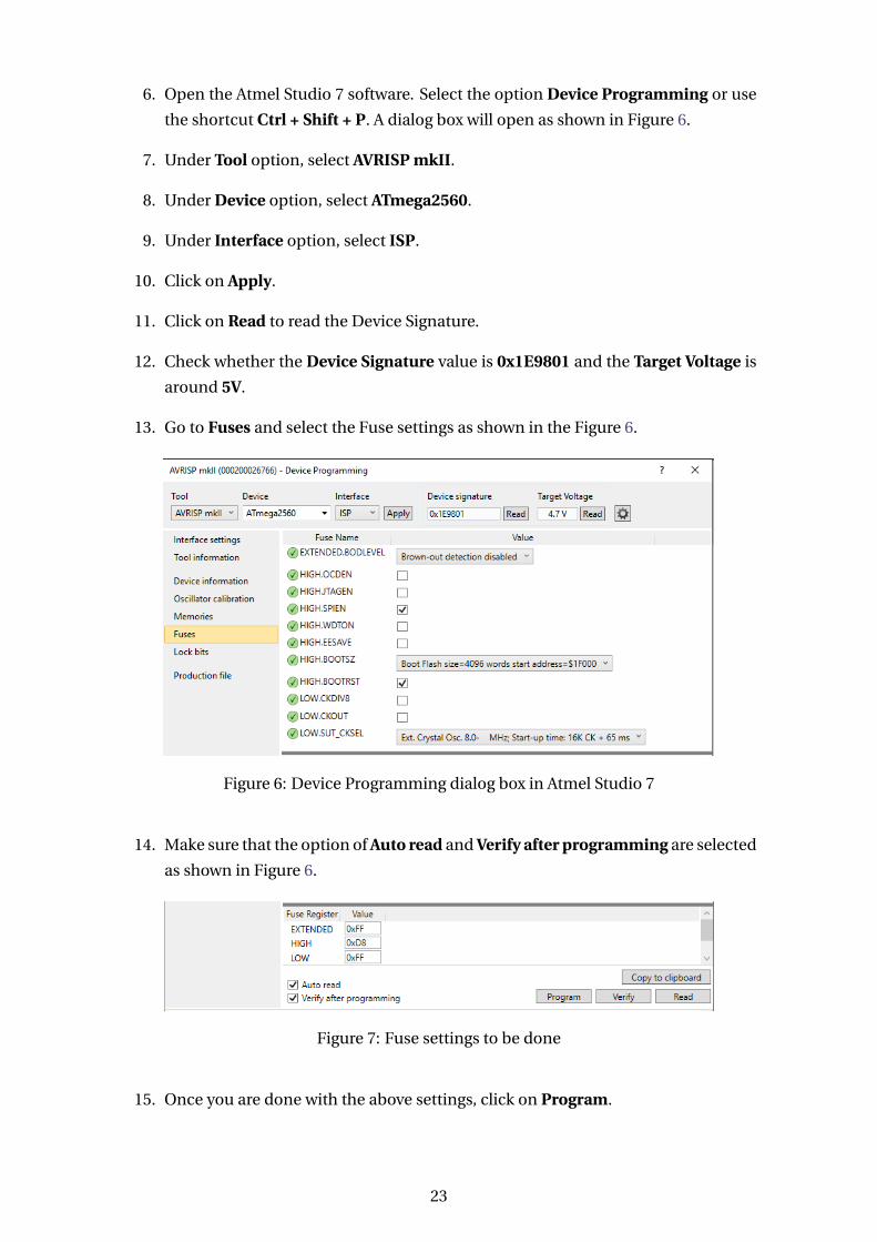
6. Open the Atmel Studio 7 software. Select the option Device Programming or use
the shortcut Ctrl + Shift + P. A dialog box will open as shown in Figure 6.
7. Under Tool option, select AVRISP mkII.
8. Under Device option, select ATmega2560.
9. Under Interface option, select ISP.
10. Click on Apply.
11. Click on Read to read the Device Signature.
12. Check whether the Device Signature value is 0x1E9801 and the Target Voltage is
around 5V.
13. Go to Fuses and select the Fuse settings as shown in the Figure 6.
Figure 6: Device Programming dialog box in Atmel Studio 7
14. Make sure that the option of Auto read and Verify after programming are selected
as shown in Figure 6.
Figure 7: Fuse settings to be done
15. Once you are done with the above settings, click on Program.
23

16. After the programming is complete, you will see the message as shown in the be-
low Figure 6.
Figure 8: All OK message after programming the Fuses
17. Go to Memories, select Erase Now to erase the ATmega2560 chip before flashing
the Boot-loader firmware on to it.
18. Make sure the options Erase device before programming and Verify flash device
after programming are selected.
19. Select the Boot-loader firmware downloaded under the Flash (256 KB) section
and press Program.
20. Once the programming is complete, you will get the message: Verifying Flash....OK.
The LED color on Atmel AVRISP mkII will turn to Orange and will blink continu-
ously.
21. Congrats! Your eYFi-Mega board is updated with the Boot-loader firmware of AT-
mega2560.
24

CFlashing Boot-loader on ESP32
Note: Refer to this section only if you have accidentally overwritten the Boot-loader
firmware / Partition Table / OTA Application of ESP32 on eYFi-Mega board.
1. To upload the Boot-loader firmware of ESP32: refer the Section Flashing eYFi-
Mega ESP32 Bootloader in the Software Manual of eYFi-Mega development board.
2. To upload the Partition Table of ESP32: refer the Section Flashing eYFi-Mega ESP32
Partition Table in the Software Manual of eYFi-Mega development board.
3. To upload the OTA Application of ESP32: refer the Section Flashing eYFi-Mega
ESP32 OTA Application in the Software Manual of eYFi-Mega development board.
25