hardware application evaluation report
TRANSCRIPT

Sylvanus Jenkins Student Number: 000449066 Course Leader: David Israel
Hardware
Application
Evaluation
Report

Sylvanus Jenkins Student Number: 000449066 Course Leader: David Israel
Content Page Introduction: ...........................................................................................................
Task one: Explaining why these particular labs have been chosen to evaluate these
particular examples of technologies use.
Task two: Discusses the advantages of both technologies using referencing citing
from other sources
Task Three: Discusses the disadvantages of both technologies using referencing
citing other sources where it has been used but has not been successful.
Task four: Evaluating the two technologies based only on the work carried out using
these technologies.
Subtask one: Defines which is better?
Subtask two: Gives reasons why preference with the technologies is made using code/
working hardware to support my arguments.
Sylvanus Jenkins Student Number: 000449066 Course Leader: David Israel
Introduction
This report will be critically reviewing two selected labs with an explanation as to how
and this labs where selected. In this report each lab selected is chosen from the two
different technology used during this course, PIC Microprocessor and Xilinx (VHDL). In
other to effectively review each technology, each task has complete a lab with each
using one of the above technology will be evaluated base upon it effective task. Both
technologies will be discussed in details as taking it to account it advantages as well as
citing and examples where it has been used and has been successful in completing that
tasks or area. To give us better understand its disadvantages will also be reviewed with
expand discussion using material where the technology has been used assessing and
why it was not successful in that area. In conclusion the two technologies will be
evaluated based only on the task it has completed with each lab. This will then be
followed by an assessment from which will assess which technology is better using
citing of other works as well as codes used with supporting working hardware where
the hardware is supported using fully functional working code and citing.
To completing the review lab three and lab twelve has been chosen. These labs
corresponds with the standard required expected with each technology so they have
been selected.
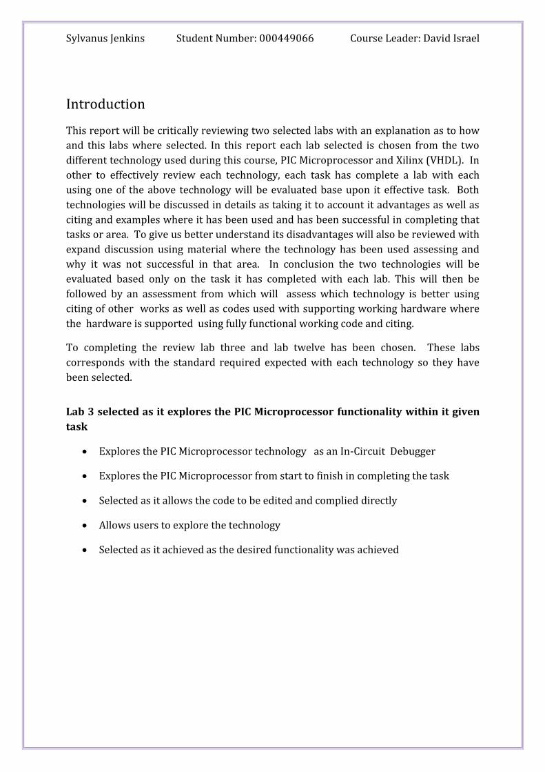
Lab 3 selected as it explores the PIC Microprocessor functionality within it given
task
Explores the PIC Microprocessor technology as an In-Circuit Debugger
Explores the PIC Microprocessor from start to finish in completing the task
Selected as it allows the code to be edited and complied directly
Allows users to explore the technology
Selected as it achieved as the desired functionality was achieved

Sylvanus Jenkins Student Number: 000449066 Course Leader: David Israel
Fig 1: Screenshot Displays Selected Lab
Task had been chosen as it explores functionality on all level of the technology this
enable full assessment of the technology suitability for it task. A task also allows MPLAB
ICD 2 an external In-Circuit Debugger to be used making it ideal for assessment.
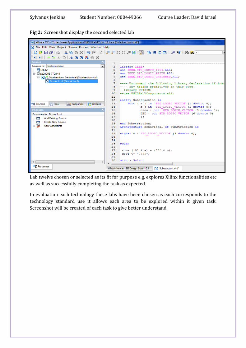
Lab 12 selected as it explores Xilinx (VHDL) features as well as it achieved the
desired functionality in its task
Selected as it explore Xilinx packages available and successfully initiated the
download through net list a feature that allows a design file to be transform in to
a net list known as a UCF file.
Explore technological aspect of the technology as well as packages and data type
that are robust and readily available upon declaration within the integrated
environment.
Explore technology within area
This lab has been chosen for critical review as both has explored each individual
technology in that particular area.
Sylvanus Jenkins Student Number: 000449066 Course Leader: David Israel
Fig 2: Screenshot display the second selected lab
Lab twelve chosen or selected as its fit for purpose e.g. explores Xilinx functionalities etc
as well as successfully completing the task as expected.
In evaluation each technology these labs have been chosen as each corresponds to the
technology standard use it allows each area to be explored within it given task.
Screenshot will be created of each task to give better understand.
Sylvanus Jenkins Student Number: 000449066 Course Leader: David Israel
Background Knowledge of Microchip IDE
MPLAB Integrated Development Environment (IDE) is a free, integrated toolset for the development of embedded applications employing Microchip's PIC® and dsPIC® microcontrollers. MPLAB IDE runs as a 32-bit application on MS Windows®, is easy to use and includes a host of free software components for fast application development and super-charged debugging. MPLAB IDE also serves as a single, unified graphical user interface for additional Microchip and third party software and hardware development tools. Moving between tools is a snap, and upgrading from the free software simulator to hardware debug and programming tools is done in a flash because MPLAB IDE has the same user interface for all tools.
Source:http://www.microchip.com/stellent/idcplg?IdcService=SS_GET_PAGE&nodeId=
1406&dDocName=en019469&part=SW007002
MPLAB IDE provides functions that allow you to: • Create and Edit Source Files • Group Files into Projects • Debug Source Code • Debug Executable Logic Using the Simulator or Emulator(s) The MPLAB IDE allows you to create and edit source code by providing you with a full-featured text editor. Further, you can easily debug source code with the aid of a Build Results window that displays the errors found by the compiler, assembler, and linker when generating executable files. A Project Manager allows you to group source files, precompiled object files, libraries, and linker script files into a project format. The MPLAB IDE also provides feature-rich simulator and emulator environments to debug the logic of executables. Some of the features are: • A variety of windows allowing you to view the contents of all data and program memory locations • Source Code, Program Memory, and Absolute Listing windows allowing you to view the source code and its assembly-level equivalent separately and together (Absolute Listing) • The ability to step through execution, or apply Break, Trace, Standard, or Complex Trigger points
Source:http://www.microchip.com/stellent/idcplg?IdcService=SS_GET_PAGE&nodeId=
1406&dDocName=en010046

Sylvanus Jenkins Student Number: 000449066 Course Leader: David Israel
How MPLAB ICD 2Works
MPLAB ICD 2 is an all-in-one debugger/programmer solution: MPLAB® ICD 2 is a
low cost, real-time debugger and programmer for selected PIC® MCUs and dsPIC® DSCs.
Using Microchip Technology's proprietary In-Circuit Debug functions, programs can be
downloaded, executed in real time and examined in detail with the debug functions of
MPLAB. Set watch variables and breakpoints from symbolic labels in C or assembly
source code, and single step through C source lines or into assembly code. MPLAB ICD 2
can also be used as a development programmer for supported MCUs.
Source:http://www.microchip.com/stellent/idcplg?IdcService=SS_GET_PAGE&nodeId=
1406&dDocName=en010046
Background Knowledge of Xilinx
Xilinx is the world’s largest suppliers for Programmable Logic Array (PLA) the inventor
Field Programmable Logic Gate Array (FPGA). Xilinx was founded in 1984 by two
semiconductor engineers. Xilinx designs, develops and markets programmable logic
products including integrated circuits (ICs), software design tools, predefined system
functions delivered as intellectual property (IP) cores, design services.
What is VHDL?
(Very High Speed Integrated Circuit) is an integrated development environment
commonly used as a design-entry language for field-programmable gate arrays etc.
VHDL is a strongly recommended language amongst many other languages. VHDL
allows users to follow these stages Design Entry (top level design file using VHDL or
schematic); Synthesis is the process of turning a design file to a netlist that is accepted
as input to the implementation step; Implementation is the process which allows the
logical design into a physical file format that can be downloaded to the target device;
Verification is the process of checking that the programmed functionality is the design
input. This process is done through simulator interpretation of the circuit functionality.
How VHDL works
VHDL is a language that can be used to describe the structure and / or
behaviour of hardware designs
VHDL designs can be simulated and / or synthesized
Hierarchical use of VHDL designs permits the rapid creation of complex
hardware designs

Sylvanus Jenkins Student Number: 000449066 Course Leader: David Israel
Advantage of Xilinx (VHDL)
The use of Very High Speed Integrated s Circuit (VHDL) as a design language is it having
many advantages to its users which will be discuss now.
The first obvious advantage that VHDL has is its Synthesis; Synthesis is the translations
of a design file into a netlist file that describes the structure of a hardware design
however even though it a major advantage
Not all VHDL statements are synthesizable
Synthesis tools cannot read the designer’s mind
VHDL next advantage is simulation; Simulation is the prediction of the behaviour of a
design file
Inputs to the simulation is usually specified
Functional simulation approximates the behaviour of a hardware design
by assuming that all outputs change at the same time
Timing simulation predicts the exact behaviour of a hardware design
VHDL is the allows users to declare and use library packages and data types which are
robust and tested time and time again and has proved themselves functional, saving the
programmer valuable time in designing their own.
It libraries provide a set of hardware designs, components, and functions that simplify
the task of designing
It packages provide a collection of commonly used data types and subprograms used in
a design
The following is an example of the use of the IEEE library and its STD_LOGIC_1164
package:
LIBRARY IEEE;
USE ieee.std_logic_1164.ALL;
There are also supports in VHDL for unsynthesizable constructs that are useful in writing high-level models, test benches and other non-hardware or non-synthesizable artifacts that we need in hardware design.
VHDL can be used throughout a large portion of the design process in different capacities, from specification to implementation to verification.
VHDL has static type checking—many errors can be caught before synthesis and/or simulation.

Sylvanus Jenkins Student Number: 000449066 Course Leader: David Israel
VHDL differentiate itself as it resembles the structure of a modern object-oriented
software design in the sense that every VHDL design describes both an external
interface and an internal implementation.

Sylvanus Jenkins Student Number: 000449066 Course Leader: David Israel
VHDL
An example where Xilinx technology were used successfully is the creation of a program
implemented a multiplexer using a three control line input producing an eight bit vector
as it output. Using a seven-segment value to represent which input line is being passed
to the display.
This example best describes
Fig 3: Screenshot displays VHDL with coding.
During the creation of the program several VHDL feature and in built functionalities
where explored e.g. declaration of libraries, packages and built in data types.
Entity (Input and output) ports where declared her)
Architecture declaration (describes the internal
interface of the program)
Library packages where declared at the top.

Sylvanus Jenkins Student Number: 000449066 Course Leader: David Israel
Coding
Library IEEE;
Use IEEE.STD_LOGIC_1164.ALL;
Entity sjenkins is
Port (CL: in STD_LOGIC_VECTOR (2 down to 0) ;
X: in STD_LOGIC_VECTOR (1 down to 0);
J: out STD_LOGIC_VECTOR (3 down to 0);
Q: in out STD_LOGIC_VECTOR (7 down to 0);
D: in out STD_LOGIC_VECTOR (7 down to 0));
End sjenkins;
Architecture Behavioural of sjenkins is
Begin
With x Select
Q <= "00000000" when "01", --1
"00000001" when "10", --2
"00000010" when "11", --3
"00000011" when "01", --4
"1000000" when others; --0
J <= "0111";
With Q Select
D <= "0000000" when "00000001", --1
"0100100" when "00000010", --2
"0110000" when "00000011", --3
"0011001" when "00000100", --4
"0010010" when "00000101", --5
"0000010" when "00000110", --6
"1111000" when "00000111", --7
"0000000" when "10000000", --8
"0010000" when "10000001", --9
"0001000" when "10000010", --A
"0000011" when "10000011", --b
"1000110" when "11000000", --C
Library declarations
The library packages and data typed were declared here.
Entity declaration
With the entity the input and output port where
defined as well as Bidirectional port. Declared
the control line two down to zero. Input was
two bit so they were declared one down to zero.
Output for selecting segment was declared as
three down to zero. Once the input and output
was declared the bidirectional was then
declared as a Std_logic_vector (7 down to 0);
Architecture declaration
Within the architecture the behaviour of the program
was defined using a with select statement, which
uses it defined setting in the entity. This area carries
out the system request of using two inputs and
producing an eight bit vector.
Here the segment which the result was going to be
displayed in was declared using it binary
representation of the number.
To produce an output of eight bit I then declared
each value within a (with select statement) to
defined the seven segment values displayed here.

Sylvanus Jenkins Student Number: 000449066 Course Leader: David Israel
"0100001" when "11000001", --d
"0000110" when "11100000", --E
"0001110" when "11111111", --F
"1000000" when others; --0
End Behavioural;

Sylvanus Jenkins Student Number: 000449066 Course Leader: David Israel
Advantage of MPLAB IDE
To balance views on both technologies MPLAB IDE will have its advantages discuss
below:
An important feature is it complier, that is used by MPLAB IDE to complied with
debugging capabilities directly inside the IDE to allow users to take full
advantage of the tool. This is an efficient application development and debugging
this is a high level language complier that MPLAB IDE has brought to users.
MPLAB comes equip with debugging facilities discussed above.
The MPLAB IDE is a simple yet powerful development environment, support low-
risk product development by providing a complete management solution for all
development system in one tool.
MAPLAB also allows user to select their device with colours used to indicate the
level of support for the selected device. It feature vary as well as configure it
changing the settings in accordance with the selected device.
MPLAB IDE allows users to select the type of language used thorough it project
wizard.
MPLAB IDE allows the testing of code through it simulation. Simulation is
software program that runs instruction of the PIC MCU.
MPLAB IDE provide a facility it called a project wizard containing the files needed
to build an application (source code, linker script files, etc.) along with their
associations to various build tools and build options.
MPLAB IDE also contains a workspace contains information on the selected device,
debug tool and/or programmer, open windows and their location and other IDE
configuration settings.
12, 14 and 16-bit wide instructions are used upward compatible and tailored to
maximize processing efficiency and boost performance.

Sylvanus Jenkins Student Number: 000449066 Course Leader: David Israel
Instruction and data are transferred on separate buses, avoiding processing
bottleneck and increasing overall system performance.
Single wide word instructions increase software code efficiency and reduce
required program memory.
Upwards device compatibility allows designers to retain their capital investment
in code development and development tool resources.
With only 33-79 instructions, programming and debugging tasks are easy to
learn and perform.
Diverse flash memory offering provide industry standard to industry leading
endurance and retention. Devices with the self-write option have the ability to
remotely program and upgrade the MCU application in the field.
An example where MPLAB technologies were used successfully is the creation of
temples using the standard building blocks. The temple created here is one that updates
and reset registers using several of instruction set instructions.
Fig 4: Screenshot shows MPLAB in use temple updating and resetting registers.

Sylvanus Jenkins Student Number: 000449066 Course Leader: David Israel
Codes
;**********************************************************************
; This file is a basic code template for object module code *
; Generation on the PICmicro PIC1658A. This file contains the *
; Basic code building blocks to build upon. As a project minimum *
; the 16c58.lkr file will also be required for this file to *
; correctly build. The .lkr files are located in the MPLAB *
; directory. *
; *
; Refer to the MPASM User's Guide for additional information on *
; features of the assembler and linker (Document DS33014F). *
; *
; Refer to the respective PICmicro data sheet for additional *
; Information on the instruction set. *
; Template file built using MPLAB V3.99.18 with MPASM V2.15.06 and *
; MPLINK 1.10.11 as the language tools. *
;**********************************************************************
; Filename: xxx.asm *
; Date: *
; File Version: *
; *
; Author: *
; Company: *
;**********************************************************************
; Files required: *
;**********************************************************************
; Notes: *
;**********************************************************************
list p=16c58a ; list directive to define processor
#include <p16c5x.inc> ; processor specific variable definitions

Sylvanus Jenkins Student Number: 000449066 Course Leader: David Israel
__CONFIG _CP_OFF & _WDT_ON & _RC_OSC
; '__CONFIG' directive is used to embed configuration word within .asm file.
; The lables following the directive are located in the respective .inc file.
; See respective data sheet for additional information on configuration word.
;***** VARIABLE DEFINITIONS
TEMP_VAR UDATA
temp RES 1 ;example variable definition
;**********************************************************************
RESET_VECTOR CODE 0x7FF ; processor reset vector
goto start
MAIN CODE 0x000
start
nop ; example code
movlw 0xFF ; example code
banksel temp ; ensure GPR bank is selected
movwf temp ; example code
; remaining code goes here
END ; directive 'end of program'

Sylvanus Jenkins Student Number: 000449066 Course Leader: David Israel
To provide a balance view as well as opinion of each technology during its task each
technology disadvantages will follow discussed below and an example as to why it was
not successful in that area.
Disadvantage of Xilinx (VHDL)
Xilinx VHDL is verbose, complicated and confusing.
The technology has many different ways of saying the same thing.
Constructs that have similar purpose have very different syntax (case vs. select)
Constructs that have similar syntax have very different semantics (variables vs. signals)
Hardware that is synthesized is not always obvious (when is a signal a flip-flop vs. latch vs. combinational)
An example where VHDL has failed its users reflected below
Not all VHDL statements are synthesizable
"ERROR: Simulator - Failed to link the design. Check to see if any previous simulation
executables are still running."
Synthesize seems to be ok, but I get this on simulate behaviour:
Running Fuse ...
fuse -intstyle ise -incremental -o jb02_tb_isim_beh.exe -prjjb02_tb_beh.prj -top jb02_tb
Running : C:\Xilinx\10.1\ISE\bin\nt\unwrapped\fuse.exe -ise C:/jon/
fpga_uarted_01/2009_01_28_jl_mod/11jlmod/uart_jb_02_goto/
uart_jb_02_goto.ise -intstyle ise -incremental -o jb02_tb_isim_beh.exe-prj jb02_tb_beh.prj
-top jb02_tb
Determining compilation order of HDL files
Analyzing VHDL file source/jb02_version_goto/New_UART_With_FIFOs/
kcuart_tx.vhd
Restoring VHDL parse-tree ieee.std_logic_1164 from c:/xilinx/10.1/ise/
vhdl/hdp/nt/ieee/std_logic_1164.vdb
Restoring VHDL parse-tree std.standard from c:/xilinx/10.1/ise/vhdl/
hdp/nt/std/standard.vdb
Using precompiled package standard from library std
Using precompiled package std_logic_1164 from library ieee
Using precompiled package std_logic_arith from library ieee
Compiling architecture lut4_v of entity lut4 [\LUT4("1110010011111111")\]
Compiling architecture lut4_v of entity lut4 [\LUT4("0000000110010000")\]
Compiling architecture lut4_v of entity lut4 [\LUT4("0001010101000000")

Sylvanus Jenkins Student Number: 000449066 Course Leader: David Israel
Source: http://newsgroups.derkeiler.com/Archive/Comp/comp.arch.fpga/2009-
02/msg00457.html
Another example of design file that is not synthesizable is time is used to simulated and
it's possible to identify the design error by observing the waveforms:
However it's more efficient to build in checks which automatically verify the result of a
simulation
.... wait for 10 ns; x1 <= '1'; x2 <= '1'; assert y = (x1 xor x2) report "E@TB: circuit failed" severity Error; wait for 10 ns; ...
A simulator executing the code will produce output similar to this:
# ** Error: E@TB: circuit failed # Time: 40 ns Iteration: 0 Instance: /tb1

Sylvanus Jenkins Student Number: 000449066 Course Leader: David Israel
Disadvantage of MPLAB (IDE)
When assembling files in a project, the only file that needs to be there (and that should be there) is the .asm file. The presence of a linker file (.lnk) in the project files causes problems with the building of a program that begins at program memory address 0 (ORG 0). Removing the linker file from the project files should remove the problem.
When c receive the error message 'The format of the file XYZ.COD can not be read or written because its extension was not recognized' (see the picture below), then add '+DF' to the compiler option string.
We only received this error on a Windows 2003 Server machine and could not reproduce it on any other operating system.
When receiving the error message 'Warning! MPLAB IDE does not currently support this OS.' on a Windows 2003 Machine, ignore it.
When receiving any warning or error message when compiling code with
MPLAB, e.g. the message above on the .COD file, then the programming of the
PICs with any programmer does not work! You will notice then that MPLAB does
not write the programming region (0x00 - 0x...) in the output window and
programming will be faster.
MPLAB
Source: http://www.hcilab.org/resources/particles/particles-programming-mplab.htm

Sylvanus Jenkins Student Number: 000449066 Course Leader: David Israel
Conclusion
To compare and contrast one technology against the other each technology will be
evaluated before a choice will be made as to which technology was more suited to its
task and whether task exchange could produce a different result, if it was to be
completed using the other technology.
MPLAB IDE
MPLAB IDE provides functions that allow you to: • Create and Edit Source Files • Group Files into Projects • Debug Source Code • Debug Executable Logic Using the Simulator or Emulator(s)
Using MPLAB IDE technology is a good language, however better understand of the
technology would have presented the user with a faster development of a program and
as well as tasks.
Xilinx VHDL
VHDL is a language that can be used to describe the structure and / or
behaviour of hardware designs
VHDL designs can be simulated and / or synthesized
Hierarchical use of VHDL designs permits the rapid creation of complex
hardware designs
VHDL is simple and easy to use; it is also easy to design a program once it set
functionality has been defined.

Sylvanus Jenkins Student Number: 000449066 Course Leader: David Israel
Evaluating both technology
MPLAB IDE Xilinx VHDL An important feature is it complier, that is
used by MPLAB IDE to complied with
debugging capabilities directly inside the IDE
to allow users to take full advantage of the
tool. This is an efficient application
development and debugging this is a high level
language complier that MPLAB IDE has
brought to users.
VHDL is the allows users to declare and use library packages and data types which are robust and tested time and time again and has proved themselves functional, saving the programmer valuable time in designing their own.
MPLAB IDE provide a facility it called a project wizard containing the files needed to build an application (source code, linker script files, etc.) along with their associations to various build tools and build options.
It libraries provide a set of hardware designs, components, and functions that simplify the task of designing
MPLAB IDE also contains a workspace contains information on the selected device, debug tool and/or programmer, open windows and their location and other IDE configuration settings.
It packages provide a collection of commonly used data types and subprograms used in a design
After carefully assessing both technology it s clear that both are used to be same job, it is
also care that both uses different functionality to get the tasks completed. However, it is
still unclear if one is better in completing its task than the other or better because of its
unique tools or features.

Sylvanus Jenkins Student Number: 000449066 Course Leader: David Israel
Appendix
FPGA
A field-programmable gate array (FPGA) is a semiconductor device that can be configured by the customer or designer after manufacturing—hence the name "field-programmable". FPGAs are programmed using a logic circuit diagram or a source code in a hardware description language (HDL) to specify how the chip will work. They can be used to implement any logical function that an application-specific integrated circuit (ASIC) could perform, but the ability to update the functionality after shipping offers advantages for many applications.
Sources: http://en.wikipedia.org/wiki/Netlist
PLA
A programmable logic array (PLA) is a programmable device used to implement
combinational logic circuits. The PLA has a set of programmable AND gate planes, which
link to a set of programmable OR gate planes, which can then be conditionally
complemented to produce an output. This layout allows for a large number of logic
functions to be synthesized in the sum of products (and sometimes product of sums)
canonical forms.
Sources: http://en.wikipedia.org/wiki/PLA
VHDL
VHDL (VHSIC (Very High Speed Integrated Circuits) hardware description language) is commonly used as a design-entry language for field-programmable gate arrays and application-specific integrated circuits in electronic design automation of digital circuits.
Sources: http://en.wikipedia.org/wiki/VHDL
MPLAB
MPLAB Integrated Development Environment (IDE) is a free, integrated gcc-based toolset for the development of embedded applications employing Microchip's PIC and dsPIC microcontrollers. The MPLAB IDE runs as a 32-bit application on Microsoft Windows, and includes several free software components for application development, hardware simulation and debugging. MPLAB also serves as a single, unified graphical user interface for additional Microchip and third party software and hardware development tools.
Sources: http://en.wikipedia.org/wiki/MPLAB
Object files

Sylvanus Jenkins Student Number: 000449066 Course Leader: David Israel
In computer science, an object file, is an organized collection of named objects, and typically these objects are sequences of microprocessor instructions in a machine code format, which may be directly executed by a computer's CPU. Object files are typically produced by a compiler as a result of processing a source code file. Object files contain compact code, and are often called "binaries".
Sources: http://en.wikipedia.org/wiki/Objectfiles
Assembler
Typically a modern assembler creates object code by translating assembly instruction mnemonics into opcodes, and by resolving symbolic names for memory locations and other entities. The use of symbolic references is a key feature of assemblers, saving tedious calculations and manual address updates after program modifications. Most assemblers also include macro facilities for performing textual substitution—e.g., to generate common short sequences of instructions to run inline, instead of in a subroutine.
Sources: http://en.wikipedia.org/wiki/Assembler
Linker
A linker is typically used to generate an executable or library by amalgamating parts of object files together. Object files for embedded systems typically contain nothing but machine code but generally, object files also contain data for use by the code at runtime: relocation information, stack unwinding information, comments, program symbols (names of variables and functions) for linking and/or debugging purposes, and other debugging information.
Sources: http://en.wikipedia.org/wiki/Linker
Emulator
An emulator duplicates (provides an emulation of) the functions of one system using a different system, so that the second system behaves like (and appears to be) the first system. This focus on exact reproduction of external behavior is in contrast to some other forms of computer simulation, which can concern an abstract model of the system being simulated.
Sources: http://en.wikipedia.org/wiki/Emulator
Debug
Debugging is a methodical process of finding and reducing the number of bugs, or defects, in a computer program or a piece of electronic hardware thus making it behave as expected. Debugging tends to be harder when various subsystems are tightly coupled, as changes in one may cause bugs to emerge in another.
Sources: http://en.wikipedia.org/wiki/Debug

Sylvanus Jenkins Student Number: 000449066 Course Leader: David Israel
Program memory
A programmable read-only memory (PROM) or field programmable read-only memory (FPROM) is a form of digital memory where the setting of each bit is locked by a fuse or antifuse. Such PROMs are used to store programs permanently. The key difference from a strict ROM is that the programming is applied after the device is constructed. They are frequently seen in video game consoles or such products as electronic dictionaries, where PROMs for different languages can be substituted.
Sources: http://en.wikipedia.org/wiki/Program Memory
Sources files
Represent the area that the file or folder is store in.
Netlist
The word netlist can be used in several different contexts, but perhaps the most popular is in the field of electronic design. In this context, a "netlist" describes the connectivity of an electronic design.
Netlists usually convey connectivity information and provide nothing more than instances, nets, and perhaps some attributes. If they express much more than this, they are usually considered to be a hardware description language such as Verilog, VHDL, or any one of several specific languages designed for input to simulators.
Sources: http://en.wikipedia.org/wiki/Netlist

Sylvanus Jenkins Student Number: 000449066 Course Leader: David Israel
References
Software used:
MPLAB IDE
VHDL Xilinx
Books Sources
Mark Zwolinski, 2000, VHDL Digital Systems, Pearson Education Limited 2000
Software Engineering with Project Management
Software Engineering 8
Sommerville, 2006
Addison Wesley
ISBN: 0321313798
Internet Sites
Amazon /FPGA-Prototyping-VHDL
http://www.amazon.com/FPGA-Prototyping-VHDL-Examples-Spartan-3/product-
reviews/0470185317
Measurement uncertainty
http://www.measurementuncertainty.org/mu/guide/introduction.html
VHDL
http://en.wikipedia.org/wiki/VHDL
People.vcu.edu
http://www.people.vcu.edu/~rhklenke/tutorials/vhdl/modules/m13_23/sld006.htm
Digital electronics
http://digitalelectronics.blogspot.com/2007/07/comparison-of-vhdl-to-other-
hardware.html
Google PIC + Microprocessor

Sylvanus Jenkins Student Number: 000449066 Course Leader: David Israel
http://www.google.co.uk/search?hl=en&ei=s13SSZKPGuSrjAfw2On1Bg&sa=X&oi=spell
&resnum=1&ct=result&cd=1&q=PIC+Microprocessor+advantages&spell=1
PIC +Microprocessor + advantages
http://www.google.co.uk/search?hl=en&ei=s13SSZKPGuSrjAfw2On1Bg&sa=X&oi=spell
&resnum=1&ct=result&cd=1&q=PIC+Microprocessor+advantages&spell=1
Microchip
http://www.microchip.com/stellent/idcplg?IdcService=SS_GET_PAGE&nodeId=1406&d
DocName=en019469&part=SW007002
Newsgroups
http://newsgroups.derkeiler.com/Archive/Comp/comp.arch.fpga/2009-
02/msg00457.html
Appdb.wine, org
http://appdb.winehq.org/objectManager.php?sClass=version&iId=11828&iTestingId=3
1998
Wikipedia
http://en.wikipedia.org/wiki/Netlist
MPLAB
http://www.hcilab.org/resources/particles/particles-programming-mplab.htm

Sylvanus Jenkins Student Number: 000449066 Course Leader: David Israel
Appendix Coding
VHDL LAB 13
Library IEEE;
Use IEEE.STD_LOGIC_1164.ALL;
Entity sjenkins is
Port (CL: in STD_LOGIC_VECTOR (2 down to 0) ;
X: in STD_LOGIC_VECTOR (1 down to 0);
J: out STD_LOGIC_VECTOR (3 down to 0);
Q: in out STD_LOGIC_VECTOR (7 down to 0);
D: in out STD_LOGIC_VECTOR (7 down to 0));
End sjenkins;
Architecture Behavioural of sjenkins is
Begin
With x Select
Q <= "00000000" when "01", --1
"00000001" when "10", --2
"00000010" when "11", --3
"00000011" when "01", --4
"1000000" when others; --0
J <= "0111";
With Q Select
D <= "0000000" when "00000001", --1
"0100100" when "00000010", --2
"0110000" when "00000011", --3
"0011001" when "00000100", --4
"0010010" when "00000101", --5
"0000010" when "00000110", --6
"1111000" when "00000111", --7
"0000000" when "10000000", --8
"0010000" when "10000001", --9
"0001000" when "10000010", --A
"0000011" when "10000011", --b
Entity declaration
With the entity the input and output port where
defined as well as Bidirectional port. Declared
the control line two down to zero. Input was
two bit so they were declared one down to zero.
Output for selecting segment was declared as
three down to zero. Once the input and output
was declared the bidirectional was then
declared as a Std_logic_vector (7 down to 0);
Architecture declaration
Within the architecture the behaviour of the program
was defined using a with select statement, which
uses it defined setting in the entity. This area carries
out the system request of using two inputs and
producing an eight bit vector.
Here the segment which the result was going to be
displayed in was declared using it binary
representation of the number.
To produce an output of eight bit I then declared
each value within a (with select statement) to
defined the seven segment values displayed here.

Sylvanus Jenkins Student Number: 000449066 Course Leader: David Israel
"1000110" when "11000000", --C
"0100001" when "11000001", --d
"0000110" when "11100000", --E
"0001110" when "11111111", --F
"1000000" when others; --0
End Behavioural;

Sylvanus Jenkins Student Number: 000449066 Course Leader: David Israel
MPLAB
Lab 3
David Israel
;MPlab 30/01/2004 edited 4/9/2007
;Demo program to turn on all LEDs on a seven segment display
;*******************************************************************
; Useful information
; Normally you use an include file for the specific PIC as commented out below
; list p=16f88
; include <p16f88.inc> this enables you to use the special register without pre defining them
; To help you understand the process the include file has been left out
;*****************************************************************************
; First you initialises the microcontroller
; This is done by defining the register and flag names with their numerical values
;**********************************************************************
status equ 03h ; Status register address
trisA equ 05h ; Sets direction of the I/O register (port A). This register is in memory bank 1
trisB equ 06h ; Sets direction of the I/O register (port B). This register is in memory bank 1
port_A equ 05h ; address of port A
port_B equ 06h ; address of port B
pulse_on equ 0ffh ; turn pulse on
pulse_off equ 00h ; turn pulse off
rp0 equ 05h ; bit in status register to select register
; bank 1 where trisA reg is stored
all_out equ 00h ; sets all register bits as output
;*******************************************************************
org 0h ; gives instruction to the assembly program to set the program at the first memory
location
goto main ; instructs the program to jump to the label "Main"

Sylvanus Jenkins Student Number: 000449066 Course Leader: David Israel
org 010h ; gives instruction to the assembly program to set this line of the program
;at memory address 0X10
main bsf status, rp0 ; sets the status register so that the program is
:looking a memory block 1
movlw all_out ; moves the value of all_out to the working register
movwf trisB ; puts the value from the working register to the special register trisA
bcf status, rp0 ; unsets the flag to the program is back looking at memory block 0
; now port_c is set up as an out put port
; it has taken four lines of to initialise port_c
signal movlw pulse_on ; Now the program can move the value pf Pulse_on to the working register
movwf port_B ; it now moves the value in the working register to port_c
; so the last two lines of code have out put the hex value of 0xff
nop ; this line just increments the program counter but changes nothing else in
the system
goto signal ; this line loops the program so it runs for ever
end ; this is an instruction to the assembler to end the program