hardware and accessories
TRANSCRIPT
WBSETCL / TECH SPEC / Rev.-0 Page 1 of 67 Hardware & Accessories
HARDWARE AND
ACCESSORIES
(for Overhead Transmission Line)
September 2021
Engineering Department
WEST BENGAL STATE ELECTRICITY TRANSMISSION COMPANY LIMITED
Regd. Office: VidyutBhawan, Block – DJ, Sector-II, Bidhannagar, Kolkata – 700091.
CIN: U40101WB2007SGC113474; Website: www.wbsetcl.in

WBSETCL / TECH SPEC / Rev.-0 Page 2 of 67 Hardware & Accessories
TECHNICAL SPECIFICATION OF HARDWARES FOR INSULATOR STRING,
CONDUCTOR AND EARTHWIRE ACCESSORIES
1. GENERAL:
1.1. SCOPE:
1.1.1 This specification covers design, type testing, manufacture, testing at manufacturer’s works
before dispatch, supply and delivery of complete hardware fittings and accessories to be used
in the construction of –
132 KV Transmission line with ACSR Panther conductor & 7/3.15 mm GSS Earth wire
220 KV Transmission line with ACSR Zebra conductor & 7/3.15 mm GSS Earth wire and
400 KV transmission line with A.C.S.R. Quad/Twin “Moose” bundled conductor and 7/3.66 mm G.S.S. earth wire.
1.1.2. The bidders shall also have to take the responsibility for matching their hardware fittings with
the Conductor/Earth wire & Insulator Disc and conduct tests on the complete string
arrangement.
1.2. STANDARDS:
1.2.1. The conductor and earth wire accessories and hardware fittings shall conform to the latest
edition of the following Indian Standards as amended up to date unless otherwise specified
hereinafter. Corresponding standards of IEC or other reputed international standards which
ensure equivalent or better quality are acceptable. In such case English version of standards
followed shall be furnished.
1.2.2. The equipment shall also comply with the latest revision of Indian Electricity Act and Electricity
Rules and any other electrical statutory provision, rules and regulations.
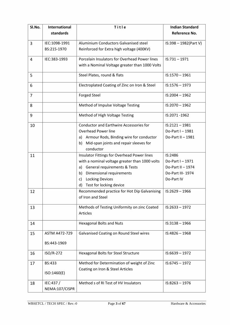
The Indian Standards, to be followed are indicated below:
Sl.No. International
standards
T i t l e Indian Standard
Reference No.
1 BS:3436-1986 Specification for Zinc IS:209 – 1996
2 BS:215-1970 Aluminium Alloy Conductors IS:398 – 1982(Part IV)
WBSETCL / TECH SPEC / Rev.-0 Page 3 of 67 Hardware & Accessories
Sl.No. International
standards
T i t l e Indian Standard
Reference No.
3 IEC:1098-1991
BS:215-1970
Aluminium Conductors Galvanised steel
Reinforced for Extra high voltage (400KV)
IS:398 – 1982(Part V)
4 IEC:383-1993 Porcelain Insulators for Overhead Power lines
with a Nominal Voltage greater than 1000 Volts
IS:731 – 1971
5 Steel Plates, round & flats IS:1570 – 1961
6 Electroplated Coating of Zinc on Iron & Steel IS:1576 – 1973
7 Forged Steel IS:2004 – 1962
8 Method of Impulse Voltage Testing IS:2070 – 1962
9 Method of High Voltage Testing IS:2071 -1962
10 Conductor and Earthwire Accessories for
Overhead Power line
a) Armour Rods, Binding wire for conductor
b) Mid-span joints and repair sleeves for
conductor
IS:2121 – 1981
Do-Part I – 1981
Do-Part II – 1981
11 Insulator Fittings for Overhead Power lines
with a nominal voltage greater than 1000 volts
a) General requirements & Tests
b) Dimensional requirements
c) Locking Devices
d) Test for locking device
IS:2486
Do-Part I – 1971
Do-Part II – 1974
Do-Part III- 1974
Do-Part IV
12 Recommended practice for Hot Dip Galvanising
of Iron and Steel
IS:2629 – 1966
13 Methods of Testing Uniformity on zinc Coated
Articles
IS:2633 – 1972
14 Hexagonal Bolts and Nuts IS:3138 – 1966
15 ASTM A472-729
BS:443-1969
Galvanised Coating on Round Steel wires IS:4826 – 1968
16 ISO/R-272 Hexagonal Bolts for Steel Structure IS:6639 – 1972
17 BS:433
ISO:1460(E)
Method for Determination of weight of Zinc
Coating on Iron & Steel Articles
IS:6745 – 1972
18 IEC:437 /
NEMA:107/CISPR
Method s of RI Test of HV Insulators IS:8263 – 1976

WBSETCL / TECH SPEC / Rev.-0 Page 4 of 67 Hardware & Accessories
Sl.No. International
standards
T i t l e Indian Standard
Reference No.
19 Methods of Switching Impulse Test on HV
Insulators
IS:8269 – 1976
20 Stock bridge Vibration Dampers for Overhead
Power Lines
IS:9708 – 1980
21 Spacers & Dampers for Quad /Twin Horizontal
Bundle Conductors
IS:10162 - 1982
22 ASTM-D1 171 Ozone test on Elastomer
23 Electric Power Connectors IS:55671
1.3. DEVIATION:
Normally the offer should be as per Technical Specification without any deviation. But any
deviation proposed must be mentioned in the Deviation Schedule. Deviation not mentioned in
‘Deviation Schedule’ will not be considered afterwards.
2. SYSTEM PARTICULARS:
2.1. Electrical System Data:
132 KV 220 KV 400 KV
Maximum Voltage (KV) 145 245 420
BIL (Impulse withstand for –ve polarity of
complete string) (KVpeak)
650 1050 1425
Frequency 50 HZ
System grounding Effectively Earth
Power frequency withstand voltage (wet)
of complete string (KVrms)
275 460 630
Switching surge withstand voltage (wet)
of complete string (KVpeak)
- - 1050
Minimum Corona extinction voltage at
50Hz
Not less than 320
KVrms phase to ground

WBSETCL / TECH SPEC / Rev.-0 Page 5 of 67 Hardware & Accessories
Radio interference voltage at one MHZ
for 305 KV phase to earth voltage
- - Not exceeding 1000
micro volts
2.2. Line Data:
i) Conductor:
a) Name ACSR “Panther” ACSR “Zebra” ACSR “Moose”
b) Strands and wire diameter of
i) Aluminium
ii)Steel
30/3.00 mm
7/3.00 mm
54/3.18 mm
7/3.18 mm
54/3.53 mm
7/3.53 mm
c) Conductor per phase 1 no. 1 no. 4 nos.
d) Spacing between the
conductors of same phase
- - 457 mm
e) Min. Conductor spacing (meter)
(Vertical)
3.9mtr 4.9mtr 8mtr
f) Configuration of conductor Triangular for
Single Ckt.
Vertical for
Double Ckt
Triangular for
Single Ckt.
Vertical for
Double Ckt
Double circuit for
400KV line: Two/
Four ACSR Moose
Twin/Quad
conductor bundled
per phase & all three
phases on vertical
configuration.
g) Overall diameter of conductor 21 mm 28.62 mm 31.77 mm
h) Sectional area of Aluminium - 418.6 mm2 515.7 mm2
i) Weight of conductor 976 Kg/Km 1621 Kg/Km 2004 Kg/Km
j) Minimum Ultimate tensile
strength of the conductor
9127 Kgf 13316 Kgf 16250 Kgf
k) Total sectional area 207 mm2 (Al) 418.6 mm2 (Al) 597 mm2
l) Modulus of elasticity (Kg/sqcm) 0.689x10⁶
m) Coefficient of linear expansion 19.3x10⁻⁶/oC

WBSETCL / TECH SPEC / Rev.-0 Page 6 of 67 Hardware & Accessories
ii) Galvanised Steel Earthwire:
* OPGW wire will run through another peak.
2.3. INSULATOR STRINGS:
For the purpose of tower design the following data of complete string shall be adopted.
Particulars
Single
Suspension
Double
Suspension
Single Tension Double Tension
220 132 220 132 220 132 220 132
Length of
Insulator string
upto conductor/
jumper points in
mm.
Max.
Min.
2415
2275
1672+
Hanger
length
2710
2570
1837+
Hanger
length
w
2675
1852+
St.
Plate
3235
3075
2131+
St.
Plate
220 KV/132 KV 400 KV
a) Size (strands & wire
diameter
7/3.15 mm 7/3.66 mm
b) Overall diameter 9.45 mm 10.98 mm
c) Standard weight 428 Kg/Km 583 Kg/Km
d) Location of earthwire One continuous earthwire to
run horizontally on top of
the tower
One continuous earthwires to
run horizontally on top of the
tower through one peak*
e) Minimum breaking load 5710 Kgf 6969 Kgf
f) Total sectional area 54.57 mm2 73.65 mm2
g) Modulus of elasticity 1.933x10⁶ g/Sqcm. 1.860x10⁶ Kg/Sqcm.
h) Co-efficient of linear
expansion
11.5x10⁻⁶/oC 11.5x10⁻⁶/oC

WBSETCL / TECH SPEC / Rev.-0 Page 7 of 67 Hardware & Accessories
Particulars
Single
Suspensio
n
String
Double
Suspension
String
Double
Tension
String
Single
Tension
String
Pilot
suspension
string
220 132 220 132 220 132 220 132 220 132
No. of Standard discs per
string
14 9 2x14 2x9 2x15 2x10 15 10 14 9
Size of disc. in mm 255x145 255x145 255x145 255x145 255x145
Eelectromechanical Failing
load of each string (KN)
70
2x70
2x120
120 70
Minimum Creepage
Distance of each disc in mm
320 320 320 320 320
Pollution level HEAVY
Particulars
Single
Suspension
Pilot String
Double
Suspension
String
Single
Tension
String
Quad /Twin
Tension
String
400 ‘I’ String 400 ‘I’ String 400 400
No. of Standard discs per string 1x23 2x23 1x24 4x23 / 2x23
Size of disc. in mm 255x145 255 x 145 255 x 145 280 x 170
Eelectrom-echanical
Failing load of each string(KN)
1x120 2x120 1x120 4X160 /
2x160
Minimum Creepage
Distance of each disc in mm
370 370 370 370
Pollution level MODERATELY
3. WORKMANSHIP:
a) All the hardware fittings and Conductor/Earthwire Accessories shall be of the latest design and conform to the modern practices adopted in the extra high voltage field. The tenderer shall offer only such equipment which is guaranteed by him to be satisfactory and suitable for transmission lines and will give continuous good performance.
b) The design, manufacturing process and quality control of all the materials shall be such as to given (i) good finish of materials, elimination of sharp edges, corners etc. to limit corona and radio interference and (ii) Maximum factor of safety and highest mobility provides best resistance to consider.

WBSETCL / TECH SPEC / Rev.-0 Page 8 of 67 Hardware & Accessories
c) All ferrous parts including bolts, nuts & washers shall be hot dip galvanised after all machining has been completed. Nuts may be tapped (threaded) after galvanising. The spring washers shall be electro galvanised. The bolt threads shall be undercut to take care of increase in diameter due to galvanising and shall be done in accordance with IS 2633-1986. Bolts, Nuts & Washers shall withstand 4(four) dips while spring washers 3 dips-other galvanised materials shall be guaranteed to withstand at least 6 successive dips each lasting 1(one) minute under standard ‘Preece’ test for galvanising.
d) The zinc coating shall be perfectly adherent, of uniform thickness, smooth, reasonably bright, continuous and free from such imperfections such as flux, ash, rust stains, bulky white deposits and blisters. The zinc used for galvanising shall be electrolytic High Grade (HG) quality of 99.95% purity. It shall conform to the requirements of IS:209 – 1992.
e) Forged/Cast fittings shall be free from all internal defects like shrinkage inclusion, blow holes, cracks etc. 100% checking of each item is to be made and a certificate to this effect is to be produced with each lot offered for inspection.
f) All current carrying part shall be designed and manufactured so that contact resistance is reduced to minimum.
g) No component shall have sharp ends or edges, abrasion or projection and cause any damage to the conductor in any way during erection or during continuous operation which would produce high electrical and mechanical stresses in normal working. The design of adjacent metal parts and machining surfaces shall be such as to prevent corrosion of the contact under service conditions.
h) All bolts and clamps shall have suitable and corona free locking arrangements and guard against vibration loosening.
i) Welding of aluminum shall be by inner gas shielded tungsten arc or inner gas shielded metal earth process. Welding should be clear, sound, smooth, and uniform without overlaps properly fused and completely shield. There should be no cracks, voids, incomplete penetration, incomplete fusion, undertaking or inclusions. Porosity shall be minimized so that mechanical strength of aluminum alloyed are affected.

WBSETCL / TECH SPEC / Rev.-0 Page 9 of 67 Hardware & Accessories
4. TECHNICAL PARTICULARS OF LINE HARDWARES
4.1. DETAILS OF HARDWARE FITTINGS:
i. General design of the hardware fittings shall be such as to ensure uniformity, high strength,
freedom from corona formation and high resistance against corrosion.
ii. All shackles, eyes, fasteners, suspension & Tension Clamp and other fittings for attaching
insulator to the tower or line Conductor shall be so designed as to reduce any damage to the
Conductor, Insulator, or the fittings arising from Conductor vibration.
iii. Smooth finished surface of all parts shall be ensured to reduce the level of RI of the line.
iv. Design of the fittings shall be such as to avoid local corona formation or discharges likely to
cause interference to telecommunication signals of any kind.
v. Adequate bearing area between fittings shall be provided and point or line contacts shall be
avoided. All current carrying parts shall be designed to have minimum contact resistance.
vi. The hardware fittings shall be as per specification and approved drawings.
vii. Each of the above hardware fittings shall be supplied complete in all respect.
viii. Standard anchor shackles for the suspension strings should be suitable for attaching to “U”
hanger of 22 mm dia to be supplied with the tower. The attachment fittings to be supplied with
the tower shall be so arranged that the place of the “U” hanger shall be transverse to the run of
the conductor.
ix. ‘D’ Shackle to be supplied shall be suitable for attaching the tension strings to the strain plates
of tower. The strain plates to be supplied with the towers will have a minimum thickness of 20
mm with vertical holes between 25 mm to 32 mm diameter.
x. Suitable yoke plates for single/double suspension and Single/Quad Tension strings for
conductor arrangements shall be supplied as per requirement.
xi. Sag adjustment Plate/turnbuckle for Quad tension/single tension assembly respectively for
400KV line only shall be supplied.
xii. Suspension and tension clamps assembly to sit all types of Conductor size are to be supplied.
xiii. Other fittings such as corona control ring (for 400KV only) arcing horns eye link, ball clevis,
socket clevis, clevis eye, clevis, chain link etc. shall have to be supplied to make the insulator
string complete.
xix. For every set of Quad tension hardware fittings, one number 250mm rigid spacer suitable for
Quad ACSR Moose conductor shall also be provided to ensure that there is no fouling of
conductors or any components of the fittings while bringing down top two conductors of Quad
bundle at the jumper connection.

WBSETCL / TECH SPEC / Rev.-0 Page 10 of 67 Hardware & Accessories
4.2. INTERCHANGEABILITY:
All the hardware fittings (Suspension and Tension type) together with ball and socket fittings
shall be of standard design so that these hardwares are interchangeable with each other.
4.3. CORONA AND RADIO INTERFERENCE PERFORMANCE:
Sharp edges on all hardware fittings shall be avoided. All surfaces must be clean, smooth,
without cuts and abrasions or projections. No part of any hardware shall be subjected to
excessive localised pressure. The hardware shall not produce noise owing to corona under the
operating conditions.
The Bidder shall guarantee the satisfactory corona and radio interference performance of the
hardware fittings offered.
4.4. HARDWARE ACCESSORIES:
A. BALL AND SOCKET DESIGNATION:
i. Ball fittings shall be made of class IV steel as per IS 2004 are equivalent grade forged in one
piece. They shall be normalised to achieve the minimum breaking strength specified in the
respective drawings. Before galvanising of ball fittings, all dying crashing in shank and on the
bearing surface of the ball shall be carefully removed without reducing the dimension below
the requirement.
Socket ends, before galvanizing shall be of uniformed contour. The bearing surface of socket
ends shall be uniformed about the entire circumference without depression of high spots. The
international contour of socket ends shall be concentrate with the axis of fittings as per IS
2486/IEC 120. The axis of the bearing surfaces of socket ends shall be coaxial with the axis of
fittings.
ii. The dimension of the ball and socket shall be of 20 mm designation in accordance with the
standard dimension as per IS:2486 (Part II) - 1974 in case of 400KV line. And the nominal pin ball
shank diameter of the insulator shall be 20 mm for tension string unit & 16 mm for suspension
string unit for 220 KV/132 KV line. All dimensions are to be checked by appropriate gauge after
galvanizing only.
iii. Ball eye/Clevis & ball/Socket Clevis.
All the load bearing HRH bolts shall be of property class 5.6 to 8.8 as per IS:6639 – 1972 with
matching property class of nuts. The bolt and nuts shall be galvanised as per IS:1367 (Part 13).
Thickness of the spring and place washers, wherever used, shall be of minimum 2.5 mm.
Split pins of Phosphor bronze / stainless steel are to be used. Clevis and eyes shall be suitable
for appropriate fittings for which they are connected. The minimum breaking strength of these
fittings shall not be less than the respective minimum breaking strength of the insulator strings.
Before assembly, all these parts are to be checked against void, internal crack etc.

WBSETCL / TECH SPEC / Rev.-0 Page 11 of 67 Hardware & Accessories
B. ANCHOR SHACKLE & CHAIN LINK:
The above fittings components shall be made of forged steel of class designation-IV as per IS
2004-1978. All the load bearing HRH bolts shall be of property class 5.6 to 8.8 as per IS:6639-
1972 with matching property class of nuts. The bolt and nuts shall be galvanised as per IS:1367
(Part 13). Thickness of the spring and plane washers, wherever used, shall be of minimum 2.5
mm. Split pins of Phosphor bronze / stainless steel are to be used. The diameter and centre
clearances will be as per matching loads to be catered. Minimum breaking strength of the
fittings will be the U.T.S. of the respective strings where the same is to be used. All these parts
are to be checked individually and thoroughly before assembly so that absence of void, internal
cracks etc. may be ensured.
C. SECURITY CLIPS AND SPLIT PINS:
Security clips for use with ball and socket coupling shall be ‘R’ shaped hump type and shall
provide positive locking of the coupling as per IS 2486 (Part IV) – 1981. The legs of the Security
Clips shall be spread after assembly in the works to prevent complete withdrawal from the
Socket. The locking device shall be resilient, corrosion of the locking device being displaced
accidentally or being rotated when in position. Under no circumstances shall the locking device
allow separation of fittings.
Split pins shall be used with cotter bolts.
Security clip and Split Pin shall be made of good quality phosphor bronze / stainless steel as per
Is-1385.
D. ARCING HORNS:
i. The Arcing horns shall be suitably designed and attached on the hardware fittings only. The
attachments shall be provided with minimum two bolts for fitting the arcing horns. It shall be
made of mild steel tube or rod and hot dip galvanised.
ii. The arcing horns to be supplied shall be either loop or ball ended rod type or tubular type. The
minimum clearance between the arcing horn and corona control rings/grading ring at nearest
point shall be 3050 mm minimum (in 400 KV).
iii. Arcing horns should be provided at both tower and line side.
iv. The air gap should be so adjusted to ensure effective operation under actual field condition.
WBSETCL / TECH SPEC / Rev.-0 Page 12 of 67 Hardware & Accessories
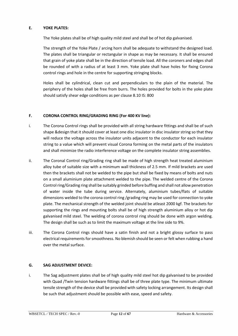
E. YOKE PLATES:
The Yoke plates shall be of high quality mild steel and shall be of hot dip galvanised.
The strength of the Yoke Plate / arcing horn shall be adequate to withstand the designed load.
The plates shall be triangular or rectangular in shape as may be necessary. It shall be ensured
that grain of yoke plate shall be in the direction of tensile load. All the coroners and edges shall
be rounded of with a radius of at least 3 mm. Yoke plate shall have holes for fixing Corona
control rings and hole in the centre for supporting stringing blocks.
Holes shall be cylindrical, clean cut and perpendiculars to the plain of the material. The
periphery of the holes shall be free from burrs. The holes provided for bolts in the yoke plate
should satisfy shear edge conditions as per clause 8.10 IS: 800
F. CORONA CONTROL RING/GRADING RING (For 400 KV line):
i. The Corona Control rings shall be provided with all string hardware fittings and shall be of such
shape &design that it should cover at least one disc insulator in disc insulator string so that they
will reduce the voltage across the insulator units adjacent to the conductor for each insulator
string to a value which will prevent visual Corona forming on the metal parts of the insulators
and shall minimize the radio interference voltage on the complete insulator string assemblies.
ii. The Coronal Control ring/Grading ring shall be made of high strength heat treated aluminium
alloy tube of suitable size with a minimum wall thickness of 2.5 mm. If mild brackets are used
then the brackets shall not be welded to the pipe but shall be fixed by means of bolts and nuts
on a small aluminium plate attachment welded to the pipe. The welded centre of the Corona
Control ring/Grading ring shall be suitably grinded before buffing and shall not allow penetration
of water inside the tube during service. Alternately, aluminium tubes/flats of suitable
dimensions welded to the corona control ring /grading ring may be used for connection to yoke
plate. The mechanical strength of the welded joint should be atleast 2000 kgf. The brackets for
supporting the rings and mounting bolts shall be of high strength aluminium alloy or hot dip
galvanised mild steel. The welding of corona control ring should be done with argon welding.
The design shall be such as to limit the maximum voltage at the line side to 9%.
iii. The Corona Control rings should have a satin finish and not a bright glossy surface to pass
electrical requirements for smoothness. No blemish should be seen or felt when rubbing a hand
over the metal surface.
G. SAG ADJUSTMENT DEVICE:
i. The Sag adjustment plates shall be of high quality mild steel hot dip galvanised to be provided
with Quad /Twin tension hardware fittings shall be of three plate type. The minimum ultimate
tensile strength of the device shall be provided with safety locking arrangement. Its design shall
be such that adjustment should be possible with ease, speed and safety.

WBSETCL / TECH SPEC / Rev.-0 Page 13 of 67 Hardware & Accessories
ii. The maximum length of the total sag adjustment device from the connecting part of rest of the
hardware fitting shall be about 520 mm. The details of maximum and minimum adjustment
possible and steps of adjustment shall be clearly indicated in the tender drawings. An
adjustment of at least 150 mm should be possible with the above device.
iii. The holes provided for bolts should satisfy shear edge conditions as per clause 8.10 of IS 800.
H. TURN BUCKLE:
The turn buckle to be provided with single tension fittings and double tension fittings shall be
made from class-II steel and shall have the minimum ultimate tensile strength of 160 KN.
The maximum length of the turn buckle from the connecting part of the rest of the hardware
fitting shall be 520 mm.
The details of the minimum and maximum adjustment possible shall be clearly indicated in the
tender. With the turn buckle and adjustment of at least 150 mm should be possible.
I. SUSPENSION CLAMP ASSEMBLY:
i. The suspension assembly shall be suitable for A.C.S.R. Moose conductor for 400 KV lines,
A.C.S.R. Zebra conductor for 220 KV and ACSR Panther conductor for 132KV lines.
ii. The suspension assembly along with standard and preformed armour rod set shall be designed
to minimise the stress and strain developed in conductor at suspension points resulting from
static and dynamic load (maximum wind pressure Aeolian vibration, broken wire condition etc.).
The suspension assembly set shall have slip strength between 20KN to 29 KN for ACSR Moose
and 8% to 15% of UTS for ACSR Zebra & ACSR Panther conductor.
iii. The Suspension assembly shall be designed, manufactured and finished to give it a suitable
shape so as to avoid any possibility of hammering between suspension assembly and conductor
due to vibration. The assembly shall be smooth, without any cuts, abrasions, projections, ridges
etc. which might damage the conductor.
iv. The magnetic power loss should not be more than 1 watt at 600 amp for ACSR Moose conductor,
1 watt at 500 amp. for ACSR Zebra conductor and 1 watt at 400 amp for ACSR Panther while
that of pilot suspension clamp (envelop type) should not be more than 2 watts at above current
ratings.
J. ARMOUR GRIP SUSPENSION CLAMP:
Armour Grip Suspension Clamp shall consist of elastomer insert, one set of Armour Rods made
of Aluminium alloy, two aluminium housing having inner profile matching with the profile of the
armour rods cage and jointed by supporting strap made of Aluminium alloy.

WBSETCL / TECH SPEC / Rev.-0 Page 14 of 67 Hardware & Accessories
The elastomer insert shall be resistant to the effects of temperature upto 85oC. Ozone,
ultraviolet radiation and other atmospheric contaminants likely to be encountered into service.
The physical properties of elastomer shall be of approved standards. It shall be electrically
shielded by a cage of A.G.S preformed rod sets. The elastomer insert shall be so designed thus
the curvature of the A.G.S rod shall follow the contour of the neoprene insert.
The A.G. Type Suspension clamp shall be so designed, manufactured and finished to have a
suitable shape without sharp angles at the end and to hold the respective conductor properly.
It should have sufficient contact surface to minimise damage due to fault current.
The A.G. Type Suspension Clamp shall permit the conductor to slip before failure of the
conductor occurs and shall have sufficient slip strength to resist the conductor tension under
broken wire condition.
K. FREE CENTRE TYPE CLAMP:
The clamp body and keeper plate shall be of high strength corrosion resistant and heat Treated
Cast/forged aluminum alloy. The components such as cotter bolts, hangers, shackles, brackets
shall be of mild steel, ‘U’ bolt shall be of stainless steel or high strength Alloy 6061. The steel
materials shall be hot dip galvanized.
L. ENVELOPE TYPE CLAMP:
The same are to be used only in Pilot insulator strings. The seat of the envelope type clamp shall
be smoothly rounded and suitably curved at the ends. The lip edges shall have round bead.
There shall be at least two ‘U’ bolts for tightening of clamp body and keeper pieces together.
Sizes of inside groove of the clamp will be such to just hold conductor only. Hexagonal bolts and
nuts with spring and plain washers of standard quality shall be used for attachment of the clamp.
M. TENSION CLAMP ASSEMBLY:
i. The tension clamp shall be suitable for specific Conductor.
ii. The tension clamp shall be of compression type with provision for compressing Jumper terminal
at one end. The angle of Jumper terminal to be mounted should be 30oC with respect to the
vertical line. The area of bearing surface on all the connectors shall be sufficient to ensure
positive electrical and mechanical contact. The conductivity of the clamp shall not be less than
that of conductor.
iii. Die compression areas shall be clearly marked on each tension clamp assembly designed for
continuous die compression and shall bear the words ‘COMPRESS FIRST’ suitably inscribed near
the point of each assembly where the compression begins. If the dead end assembly is designed
for intermittent die compression it shall bear identification marks “COMPRESSION ZONE” and
“NONCOMPRESSION ZONE” distinctly with arrow marks showing the direction of compression

WBSETCL / TECH SPEC / Rev.-0 Page 15 of 67 Hardware & Accessories
and knurling marks showing the end of the zones. The letters, number and other markings on
the finished clamp shall be distinct and legible.
iv. The clamp shall not permit slipping at a load less than 95% of the ultimate tensile strength of
the conductor. Its outer sleeve shall be made out of EC grade Aluminium of purity not less than
99.5% for ACSR conductor and high strength Aluminium Alloy of type 6201 or equivalent for
AAAC. The steel sleeve shall be made of mild steel and hot dip galvanised.
N. FASTENERS:
i. All fasteners shall be as per IS:6639-1972. All bolt heads and nuts shall be hexagonal and when
required the nuts shall be locked in an approved manner. All fasteners shall be hot dip
galvanised including the threaded portion of the bolts.
ii. Fully threaded bolts shall not be used. Length of threaded shall be such that no thread shall be
extended into the plane of contact of the component parts but shall be sufficient to take full
depth of the nuts and threaded enough to permit firm gripping of the component parts only. It
shall be also ensured that the threaded portion of the bolt protrudes not less than 5 mm and
not more than 10 mm when fully tightened. Flat washer and spring washer shall be provided as
required. Thickness of washer shall conform to IS:2016-1967.
iii. Fasteners of grade higher than 8.8 are to be avoided.
O. PREFORMED ARMOUR RODS:
i. This shall be provided at all suspension points of each sub-conductor/conductor to minimise
the stress and strain developed in the conductor at suspension supports resulting from static
and dynamic loads (viz. Maximum wind pressure, Aeolian vibrations, broken wire conditions
etc.). They shall also withstand power arcs, abrasions from clamps and localised heating effect
due to magnetic power losses of the clamps.
ii. The preformed armour rods shall be made of high strength special aluminium alloy. The alloy
shall be properly heat treated during manufacturing process. Conductivity of each strand of
Armour rod shall not be less than 40% of the conductivity of International Annealed Copper
Standard (IACS). Number of Armour rods in each set shall not be less than twelve for AGS
suspension clamp. The ends of Armour rods shall be parrot billed type. The armour rods shall
be capable of being fixed by hand on the conductor without the aid of any tool. The direction of
the helix (right hand lay) shall be same as that of the conductor and internal dia of the helix shall
be less than the conductor dia. so as to grip the same tightly. Each set shall be suitably marked
with black paint at its centre for easy application on the line. The armour rod shall not lose their
resilience even after five applications. The surface of armour rods when fitted on the conductor
shall be smooth and free from projections, cuts and abrasions etc.

WBSETCL / TECH SPEC / Rev.-0 Page 16 of 67 Hardware & Accessories
iii. The armour rods shall have perfect uniformity of pitch and diameter within the limit of tolerance
not exceeding +/- 1%. Each strand of the preformed armour rods shall be interchangeable with
any other strands.
iv. The armour rods should not lose resilience even after 5 applications.
v. The length of the A.G.S preformed rod shall be such that it shall ensure sufficient sliping strength
and shall not introduce unfavourable stress on the under all operating conditions. However,
the length of the A.G.S preformed rods shall not be less than as mentioned in S.T.P. The
tolerance in length of completed set should be within thirteen mm between longest and
shortest rod.
P. BALANCING WEIGHTS:
For limiting the swings of 400KV single suspension pilot insulator string used for jumper
connection at the transposition towers or in similar uses from excessive deflection, suitable
balancing weights about 200kg are to be suspended through the line side yoke plate. Each unit
shall be of multiple of 50kgs weight and shall be connected to the yoke plate by means of eye
bolts and shackle arrangement.
The balancing weight shall be of malleable cast iron / machined miled steel with sharp edges
and shall be hot dip galvanised.
The bottom weight shall be provided with recess to shield the ends of eye bolts. The same shall
be suitable for use on specific transmission lines.
4.5. INSULATOR HARDWARE COMPONENT DETAILS
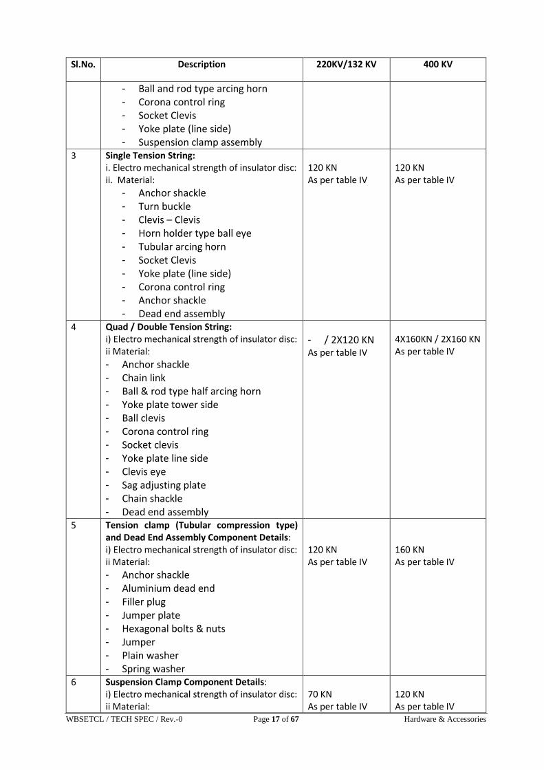
Sl.No. Description 220KV/132 KV 400 KV
1 Single Suspension String: i. Electro mechanical strength of insulator disc: ii. Material:
- Anchor shackle - Horn holder type ball eye - Full arcing horn set - Corona control ring - Socket clevis - Yoke Plate line side - Suspension clamp assembly - U-clevis (for AGS type)
70 KN As per table IV
120 KN As per table IV
2 Double Suspension String: i. Electro mechanical strength of insulator disc: ii. Material:
- Anchor shackle - Yoke plate (tower side) - Clevis – Clevis
2x70 KN As per table IV
2X120 KN As per table IV
WBSETCL / TECH SPEC / Rev.-0 Page 17 of 67 Hardware & Accessories
Sl.No. Description 220KV/132 KV 400 KV
- Ball and rod type arcing horn - Corona control ring - Socket Clevis - Yoke plate (line side) - Suspension clamp assembly
3 Single Tension String: i. Electro mechanical strength of insulator disc: ii. Material:
- Anchor shackle - Turn buckle - Clevis – Clevis - Horn holder type ball eye - Tubular arcing horn - Socket Clevis - Yoke plate (line side) - Corona control ring - Anchor shackle - Dead end assembly
120 KN As per table IV
120 KN As per table IV
4 Quad / Double Tension String: i) Electro mechanical strength of insulator disc: ii Material:
- Anchor shackle - Chain link - Ball & rod type half arcing horn - Yoke plate tower side - Ball clevis - Corona control ring - Socket clevis - Yoke plate line side - Clevis eye - Sag adjusting plate - Chain shackle - Dead end assembly
- / 2X120 KN As per table IV
4X160KN / 2X160 KN As per table IV
5 Tension clamp (Tubular compression type) and Dead End Assembly Component Details: i) Electro mechanical strength of insulator disc: ii Material:
- Anchor shackle - Aluminium dead end - Filler plug - Jumper plate - Hexagonal bolts & nuts - Jumper - Plain washer - Spring washer
120 KN As per table IV
160 KN As per table IV
6 Suspension Clamp Component Details: i) Electro mechanical strength of insulator disc: ii Material:
70 KN As per table IV
120 KN As per table IV

WBSETCL / TECH SPEC / Rev.-0 Page 18 of 67 Hardware & Accessories
Sl.No. Description 220KV/132 KV 400 KV
- Clamp body - Keeper - U bolt with nuts - Plain washers - Hex. bolts - Jumper - Saddle - Line strap - Twisted shackle
7 Armour Gri: i) Electro mechanical strength of insulator disc: ii Material:
- Armour rod type retaining rods - Neoprene cushion - Clamp body - Round strap - Hex. bolts with nut - Spring washer - Plain washer - Split pin
70 KN As per table IV
120 KN As per table IV
TABLE IV
DETAILS OF MATERIALS FOR HARDWARE FITTINGS AND ACCESSORIES
Sl. No.
NAME OF ITEM MATERIAL PROCESS OF TREATMENT
REFERENCE STANDARD
REMARKS
1. Security Clips Stainless Steel / Phosphor Bronze
- AISI 302 or 304-L / IS:1385-1968
2. Arcing Horn Mild Steel Rod / Tube type
Hot Dip Galvanised
As per IS:226-1975 or IS:206201992
3. Ball fittings, Socket All Shackles, link clevis
Class IV forged steel Forged and normalised Hot Dip Galvanised
As per IS:2004-1978
4. Yoke Plate Mild Steel Hot Dip Galvanised
As per IS:226-1975 or IS:2062-1992
5. Sag Adjustment Plate
Mild Steel Hot Dip Galvanised
As per IS:226-1975 or IS:2062-1992
6. (a) Corona Control Rings
High strength Alumi9nium Alloy tube
Heat treated ASTM-B429 Or as per IS:226 or IS:2062
Mechanical strength of welded joints
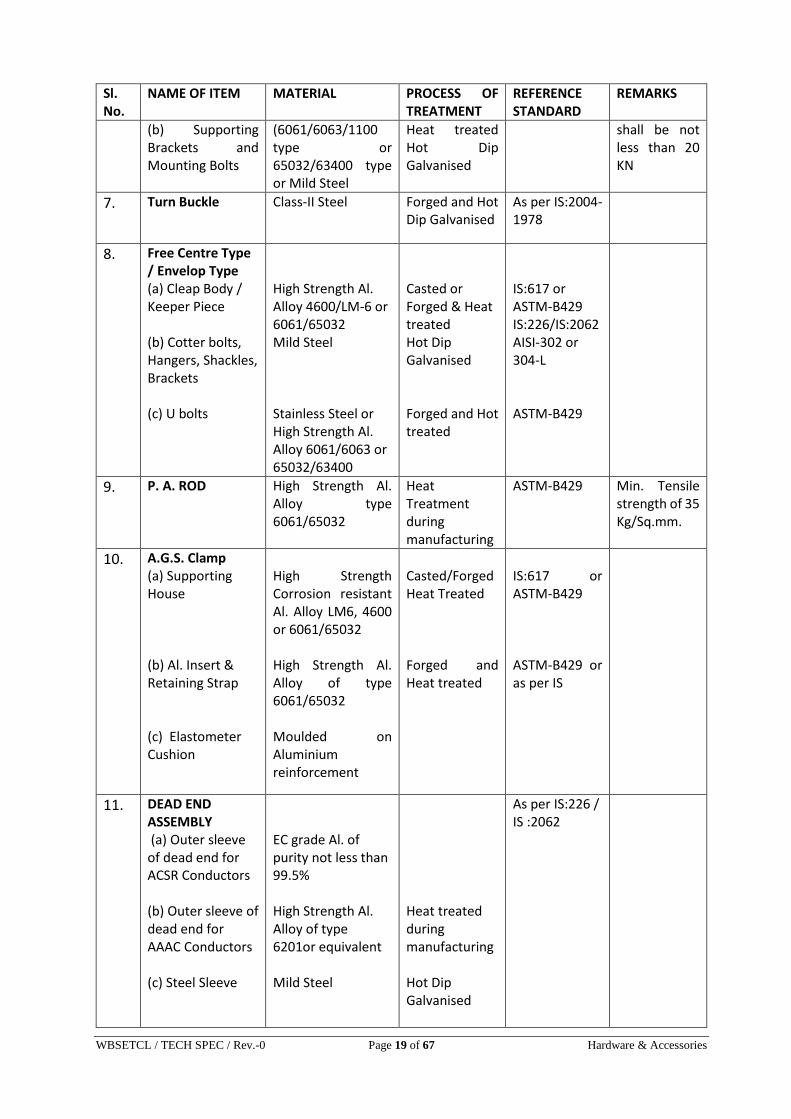
WBSETCL / TECH SPEC / Rev.-0 Page 19 of 67 Hardware & Accessories
Sl. No.
NAME OF ITEM MATERIAL PROCESS OF TREATMENT
REFERENCE STANDARD
REMARKS
(b) Supporting Brackets and Mounting Bolts
(6061/6063/1100 type or 65032/63400 type or Mild Steel
Heat treated Hot Dip Galvanised
shall be not less than 20 KN
7. Turn Buckle Class-II Steel Forged and Hot Dip Galvanised
As per IS:2004-1978
8. Free Centre Type / Envelop Type (a) Cleap Body / Keeper Piece (b) Cotter bolts, Hangers, Shackles, Brackets (c) U bolts
High Strength Al. Alloy 4600/LM-6 or 6061/65032 Mild Steel Stainless Steel or High Strength Al. Alloy 6061/6063 or 65032/63400
Casted or Forged & Heat treated Hot Dip Galvanised Forged and Hot treated
IS:617 or ASTM-B429 IS:226/IS:2062 AISI-302 or 304-L ASTM-B429
9. P. A. ROD High Strength Al. Alloy type 6061/65032
Heat Treatment during manufacturing
ASTM-B429 Min. Tensile strength of 35 Kg/Sq.mm.
10. A.G.S. Clamp (a) Supporting House (b) Al. Insert & Retaining Strap (c) Elastometer Cushion
High Strength Corrosion resistant Al. Alloy LM6, 4600 or 6061/65032 High Strength Al. Alloy of type 6061/65032 Moulded on Aluminium reinforcement
Casted/Forged Heat Treated Forged and Heat treated
IS:617 or ASTM-B429 ASTM-B429 or as per IS
11. DEAD END ASSEMBLY (a) Outer sleeve of dead end for ACSR Conductors (b) Outer sleeve of dead end for AAAC Conductors (c) Steel Sleeve
EC grade Al. of purity not less than 99.5% High Strength Al. Alloy of type 6201or equivalent Mild Steel
Heat treated during manufacturing Hot Dip Galvanised
As per IS:226 / IS :2062
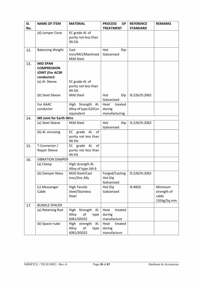
WBSETCL / TECH SPEC / Rev.-0 Page 20 of 67 Hardware & Accessories
Sl. No.
NAME OF ITEM MATERIAL PROCESS OF TREATMENT
REFERENCE STANDARD
REMARKS
(d) Jumper Cone EC grade Al. of purity not less than 99.5%
12. Balancing Weight Cast Iron/MCI/Machined Mild Steel
Hot Dip Galvanised
13. MID SPAN COMPRESSION JOINT (For ACSR conductor): (a) Al. Sleeve (b) Steel Sleeve
EC grade Al. of purity not less than 99.5% Mild Steel
Hot Dip Galvanised
IS:226/IS:2062
For AAAC conductor
High Strength Al. Alloy of type 6201or equivalent
Heat treated during manufacturing
14. MS Joint for Earth Wire
(a) Steel Sleeve Mild Steel Hot Dip Galvanised
IS:226/IS:2062
(b) Al. encasing EC grade Al. of purity not less than 99.5%
15. T-Connector / Repair Sleeve
EC grade Al. of purity not less than 99.5%
16. VIBRATION DAMPER
(a) Clamp High strength Al. Alloy of type LM-6
(b) Damper Mass Mild Steel/Cast Iron/Zinc Ally
Forged/Casting Hot Dip Galvanised
IS:226/IS:2062
(c) Messenger Cable
High Tensile Steel/Stainless Steel
Hot Dip Galvanised
IS:4826 Minimum strength of cable 135kg/Sq.mm
17. BUNDLE SPACER
(a) Retaining Rod High Strength Al. Alloy of type 6061/65032
Heat treated during manufacture
(b) Spacer tube High strength Al. Alloy of type 6061/65032
Heat treated during manufacture

WBSETCL / TECH SPEC / Rev.-0 Page 21 of 67 Hardware & Accessories
5. ACCESSORIES FOR ACSR CONDUCTOR AND GALVANISED STEEL EARTHWIRE:
5.1. CONDUCTOR ACCESSORIES:
A. Repair Sleeves:
The compression type repair sleeves for conductor are required for repairing the minor
damages on the aluminium strands of the conductor. The repair sleeves will be used where the
damage is limited to two strands of outer layer of conductor strands. The sleeves hall comprise
of two pieces, one sliding in the other. The edges of the two pieces of repair sleeve shall be
properly rounded so that the conductor strands are not damaged during installation. The repair
sleeve shall be made by extrusion process and shall be manufactured of EC grade aluminium of
99.5% purity. After compression, the sleeve shall have smooth surface. The portion where repair
sleeves provided shall have resistance less than 75% of the equivalent length of conductor.
B. Mid-span compression joints:
i. Compression type mid span joints are required for jointing of Moose Conductor. The joint shall
have a resistance less than 75% of the equivalent length of the conductor. The joint shall not
permit slipping off, damage to or failure of the complete conductor or any part thereof at a load
less than 95% of the UTS of the conductor. The joint shall comprise of steel and aluminium
sleeves for steel core and aluminium core respectively. The steel sleeve shall be hot dip
galvanised as per relevant IS specifications. The Brinneal hardness no. of the steel plate shall
not exceed 200.
ii. For ACSR Conductor the Aluminium sleeve shall be made of 99.5% purity EC Grade aluminium
and should be made by extrusion process. Compression and non-compression zones to be
marked clearly on the aluminium sleeve either by providing holes (to be plugged by Aluminium
filler plugs subsequently) or by knurling marks.
iii. For AAAC Conductor the Aluminium sleeve to be provided shall be made of aluminium alloy of
type 6201 or equivalent.
C. VIBRATION DAMPERS (for Zebra and Panther Conductor):
i. Suitable 4R Stock Bridge type vibration dampers shall be used at all tension and suspension
points on each sub-conductor/conductor in each span. The damper shall eliminate fatigue on
the conductor and damp out the vibrations effectively, so that the dynamic strain at the
suspension point/tension point shall not exceeds 150 micro strains. The Bidder shall furnish,
with supporting calculations, the required damper placement ranging from 100 metre to 800
metres. The minimum no. of vibration damper per conductor for suspension and tension tower
shall be 2 for Ruling Design Span.

WBSETCL / TECH SPEC / Rev.-0 Page 22 of 67 Hardware & Accessories
ii. The clamp of the vibration damper shall be made of high strength aluminium alloy of type LM-
6, so designed that it is capable of supporting the damper during installation and to prevent any
damage to conductor including chafing during erection or continued operation.
iii. The messenger cable shall be made of high tensile steel strands or spring and performed in
order to prevent subsequent fall of weights in service. The number of strands in the messenger
cable shall be 19 each having a minimum strength of 135 Kgf/mm2.
iv. Clamping bolts shall be provided with self-locking nuts designed to prevent corrosion of the
threads or loosening during service, ensuring that no slippage occurs on clamp along with
conductor. All ferrous parts including the messenger cable shall be effectively sealed to prevent
corrosion. The damper mass shall be made of hot dip galvanised mild seel/cast iron or zinc alloy.
All castings shall be free from defects and the surface to be smooth.
V. The clamp shall be capable of being removed and reinstalled on the conductor at the designed
torque without shearing or damaging bolts, nuts or cap screws.
vi. The vibration damper shall not have magnetic power loss more than 1 watt at 500 amps. 50 Hz
for ACSR Zebra and at 400amps.50 Hz for ACSR Panther conductor.
vii. The vibration analysis of the system, with and without damper, dynamic characteristic of the
dampers, slip strength & fatigue test on damper shall have to be submitted by the Bidder along
with the bid.
D. Spacer Damper (for Quad bundle conductor):
i. Suitable spacer dampers for four bundle ACSR MOOSE conductor for 400 kV (Quad/Twin)
line shall be offered. The spacer damper covered by this specification shall be designed to
maintain the bundle spacing of 457 mm under all normal operating conditions and to
effectively control Aeolian vibrations as well as sub span oscillation and to restore conductor
spacing after release of any external extraordinary load. The nominal sub conductor spacing
shall be maintained within ±5 mm.
ii. The spacer damper shall restore the normal sub-conductor spacing due to displacement by
wind, electromagnetic and electrostatic forces including the specified short circuit level
without permanent deformation or damage either to bundle conductors or to spacer
damper itself.
iii. The design offered shall be presented as a system consisting of spacer dampers and their
staggering scheme for spans ranging from 100 m to 1100 m. A vibration performance test
shall be carried out on an experimental test line. The systems tested should be those
specified by the Supplier for the 800 kV line conditions. Only systems satisfying the
performance criteria under Annexure-A shall be submitted by Bidder along with bid.
The test line selected for the performance evaluation shall have been designed for that
purpose, be adequately exposed to wind and properly instrumented.

WBSETCL / TECH SPEC / Rev.-0 Page 23 of 67 Hardware & Accessories
iv. Under the operating conditions, the spacer damper system shall adequately control Aeolian
vibrations throughout the life of the transmission line with wind velocity ranging from 0 to
30 km per hour in order to prevent damage to conductor at suspension clamps, dead end
clamps and spacer damper clamps.
v. The spacer damper system shall also control the sub-span oscillations in order to prevent
conductor damage due to chaffing and severe bending stresses at the spacer damper
clamps as well as suspension and dead end clamps and to avoid wear to spacer damper
components.
vi. The spacer damper shall consist of a rigid central body called the frame linked to the
conductor by four articulated arms terminated by suitable clamping system. The
articulation shall be designed to provide elastic and damping forces under angular
movement of the arms. The dynamic characteristics of the articulations shall be maintained
for the whole life of the transmission line.
vii. The clamping system shall be designed to provide firm but gentle and permanent grip while
protecting the conductor against local static or dynamic stresses expected during normal
operating conditions. The clamping system shall be designed to compensate for any
reduction of conductor diameter due to creep.
viii. Bolted type clamps shall allow installation without removal of the bolts or the clamps from
clamp body. Locking mechanism shall be suitable to prevent bolt loosening. Clamp locking
devices with small loose components shall not be accepted. Nut cracker, hinged open or
boltless type clamps are acceptable provided adequate grip can be maintained on the
conductor.
ix. Bolts and nuts shall be of mild steel, stainless steel, or high strength steel in accordance with
the design of the spacer damper.
x. Where elastomer surfaced clamps are used, the elastomer elements shall be firmly fixed to
the clamp. The insert should be forged from aluminium alloy of type 6061 or equivalent
aluminium alloy having minimum tensile strength of 25 kg/mm2. The insert shall be
moulded on the insert surface. The insert shall be duly heat treated and aged to retain its
consistent characteristics during service. The grain flow of the forged insert shall be in the
direction of the maximum tension and compression loads experienced.
xi. If clamps involving preformed rods are used, these rods shall be designed for specific
conductor size. They shall be made of high strength aluminium alloy of type 6061 or
equivalent aluminium alloy having a minimum tensile strength of 35 kg/mm3. The rods shall
be ball ended. The rods shall be heat treated and aged to achieve specified mechanical
properties and to retain the same during service. The length of the rods shall be such that
the ends fall inside the imaginary square whose sides are vertical and horizontal outer
tangents to the conductor sections.
xii. The spacer damper body shall be cast/forged from suitable high strength corrosion resistant
aluminum alloy. The aluminium alloy shall be chosen in relation with the process used.

WBSETCL / TECH SPEC / Rev.-0 Page 24 of 67 Hardware & Accessories
xiii. The rubber components involved in the design such as damping elements shall be made
with rubber compound selected specifically for that particular application. The Bidder shall
submit a complete list of physical and mechanical properties of the elastomer used. This
list shall make reference to all applicable ASTM standards.
xiv. The rubber components used shall have good resistance to the effects of temperature up
to 95°C and to ultraviolet radiation, ozone and other atmospheric contaminants. The
rubber shall have good wear and fatigue resistance and shall be electrically semi-
conductive.
xv. The spacer damper involving ferrous material shall not have magnetic power loss more than
that stipulated in the Standard Technical Particulars at 500 A, 50 Hz alternating current per
sub-conductor.
xvi. The spacer damper assembly shall have electrical continuity. The electrical resistance
between the sub-conductors across the assembly in case of spacer damper involving
elastomer surfaced clamps shall be suitably selected by the manufacturer to ensure
satisfactory electrical performance and avoid deterioration of elastomer under service
conditions.
xvii. The spacer damper assembly shall have complete ease of installation and shall be capable
of removal/reinstallation without any damage.
xviii. The spacer damper assembly shall be capable of being installed and removed from the
energized line by means of hot line techniques. The Bidder shall supply with the bid the
complete description of the installation, removal and reinstallation procedure.
xix. The Bidder shall recommend the staggering scheme for installation of spacer dampers on
the line which shall ensure most satisfactory fatigue performance of the line as specified.
The scheme shall indicate the number of spacer dampers per phase per span and the sub
span lengths to be maintained between spacer dampers while installing on the four bundle
conductors.
xx. The staggering scheme shall be provided for spans ranging from 100 m to 1100 m. The
number of spacer dampers for a nominal ruling span of 400 m shall not be less than six.
xxi. No sub span shall be greater than 70 m and no end sub span shall be longer than 40 m.
xxii. The staggering scheme shall be such that the spacer dampers be unequally distributed along
the span to achieve sufficient detuning of adjacent subs pans for oscillations of sub span
mode and to ensure bundle stability for wind speeds up to 60 km/hr.
xxiii. The Bidder shall furnish all the relevant technical documents in supports of the staggering
scheme recommended for the spacer damper.

WBSETCL / TECH SPEC / Rev.-0 Page 25 of 67 Hardware & Accessories
E. Rigid Spacer for Jumper of Quad Conductor:
Jumpers at tension points shall be fitted with spacers so as to limit the length of free
conductor to 3.65 m and to maintain the sub conductor spacing of 457 mm 400 kV (Quad)
line. Bidder shall quote for rigid spacer for jumper. It shall meet all the requirements of
spacer used in line except for its vibration performance. Spacers requiring retaining rods
shall not be quoted for jumpers.
The spacer offered by the Bidder shall satisfy the following requirements.
Spacer shall restore normal spacing of the sub conductors after displacement by wind,
electromagnetic and the electrostatic forces under all operating conditions including the
specified short circuit level without permanent deformation damage either to conductor or
to the assembly itself. They shall have uniform grip on the conductor
For spacer requiring retaining rods, the retaining rods shall be designed for the specified
conductor size. The preformed rods shall be made of high strength, special aluminium alloy
of type 6061/65032 and shall have minimum tensile strength of 35 kg/sq.mm. The ends of
retaining rods should be ball ended. The rods shall be heat-treated to achieve specified
mechanical properties and give proper resilience and retain the same during service.
Four number of rods shall be applied on each clamps to hold the clamp in position. The
minimum diameter of the rods shall be 7.87 + 0.1 mm and the length of the rods shall not
be less than 1100 mm.
Where elastomer surfaced clamp grooves are used, the elastomer shall be firmly fixed to
the clamp. The insert should be forged from aluminium alloy of type 6061/65032. The insert
shall be duly heat treated and aged to retain its consistent characteristics during service.
Any nut used shall be locked in an approved manner to prevent vibration loosening. The
ends of bolts and nuts shall be properly rounded for specified corona performance or
suitably shielded.
Clamp with cap shall be designed to prevent its cap from slipping out of position when being
tightened.
The clam grooves shall be in uniform contact with the conductor over the entire surface,
except for rounded edges. The groove of the clamp body and clamp cap shall be smooth
and free of projections, grit or other material. which cause damage to the conductor when
the clamp is installed.
For the spacer involving bolted clamps, the manufacturer must indicate the clamp bolt
tightening torque to ensure that the slip strength of the clamp is maintained between 2.5
kN and 5 kN. The clamp when installed on the conductor shall not cause excessive stress
concentration on the conductor leading to permanent deformation of the conductor
strands and premature fatigue failure in operation.
Universal type bolted clamps, covering a range of conductor sizes, will not be permitted.

WBSETCL / TECH SPEC / Rev.-0 Page 26 of 67 Hardware & Accessories
No rubbing, other than that of the conductor clamp hinges or clamp swing bolts, shall take
place between any parts of the spacer. Joint incorporating a flexible medium shall be such
that there is no relative slip between them.
The spacer shall be suitably designed to avoid distortion or damage to the conductor or to
themselves during service.
Rigid spacers shall be acceptable only for jumpers.
The spacer shall not damage or chafe the conductor in any way which might affect its
mechanical and fatigue strength or corona performance.
The clamping system shall be designed to compensate for any reduction in diameter of
conductor due to creep.
The spacer assembly shall not have any projections, cuts, abrasions etc. or chattering parts
which might cause corona or RIV.
The spacer tube shall be made of aluminium alloy of type 6061/65032. If fasteners of ferrous
material are used, they shall conform to and be galvanised conforming to relevant Indian
Standards. The spacer involving ferrous fasteners shall not have magnetic power loss more
than one watt at 600 Amps 50 Hz alternating current per sub conductor.
Elastomer, if used, shall be resistant to the effects of temperature up to 95 deg.C, ultraviolet
radiation and other atmospheric contaminants likely to be encountered in service. It shall
have good fatigue characteristics. The physical properties of the elastomer shall be of
approved standard.
The spacer assembly shall have electrical continuity. The electrical resistance between the
sub-conductor across the assembly in case of spacer having elastomer clamp grooves shall
be suitably selected by the manufacturers to ensure satisfactory electrical performance and
to avoid deterioration of elastomer under all service conditions.
The spacer assembly shall have complete ease of installation and shall be capable of
removal/reinstallation without any damage.
The spacer assembly shall be capable of being installed and removed from the energised line
by means of hot line technique.
F. T – CONNECTOR:
The connector shall be of compression type and shall be used for jumper connection at
transposition towers. It shall be made of E.C. grade aluminium of 99.5% purity and shall be
strong enough to withstand normal working load. The connector shall have a resistance across
jumper less than 75% resistance of equivalent length of conductor. The welded portions shall
be designed for 30KN tensile load.

WBSETCL / TECH SPEC / Rev.-0 Page 27 of 67 Hardware & Accessories
G. Compression Markings: Die compression areas shall be clearly marked on each equipment
designed for continuous die compression and shall bear the words ‘COMPRESS FIRST ’ suitably
inscribed suitable near the point of each equipment where the compression begins. If the
equipment is designed for intermittent die compression it shall bear identification marks
“COMPRESSION ZONE” and “NONCOMPRESSION ZONE” distinctly with arrow marks showing
the direction of compression and knurling marks showing the end of the zones. The letters,
number and other markings on the finished clamp shall be distinct and legible
5.2. EARTHWIRE ACCESSORIES:
A. Suspension clamp assembly:
Free centre type suspension clamps made of heat treated malleable iron or forged steel of
suitable size are required for holding the galvanised steel stranded earthwire of 7/3.66 mm size
at suspension points, the suspension assembly shall conform to IS:2486/1971.
There shall be no sharp point in the clamp coming in contact with earthwire nor any part of the
earthwire should be displaced, damaged or unduly stressed in final assembly during working
condition. The keeper piece and the clamp body shall be clamped by at least two inverted type
U-bolt & nut and one nut shall be long enough to accommodate the lug of the flexible copper
bond for connecting with tower body.
Eye hook for clamp shall be supplied for attaching to the hanger plate having a minimum
thickness 12 mm with a hole of 21.5 mm diameter.
The major component of suspension assembly includes shackles, bolts, nuts, washers, pin etc.
The complete suspension clamp assembly shall be guaranteed for a slip strength of not less than
12KN but at the same time shall not be more than 17KN for 7/3.66 mm galvanized steel
earthwire and in between 18% to 25% of UTS of 7/3.15 mm earth wire.
B. Tension clamp Assembly:
i Compression type tension clamp complete with anchor shackles, bolts, nuts, split pin, washers
jumper arrangement etc. suitable for respective size of galvanised steel earth wire shall be
offered to hold the earthwire at all tension towers. The tension clamp shall be made of mild
steel with Al. encasing. The anchor shackle and bolts & nuts shall be of galvanised steel. One of
the bolts holding the jumper clamp shall be sufficiently long and shall be provided with locking
nuts etc. for connecting flexible earthing bond between the tension clamp and the tower
structure.
ii. The Anchor Shackle shall be suitable for attaching the; tension clamp with the strain plates of
tower the minimum thickness of strain plates will be 20 mm for 7/3.15 mm earth wire and 10
to 16 mm for 7/3.15 mm earth wire with provision of one 25 to 32 mm diameter hole. The angle
of jumper terminal to be mounted should be 30o with respect to vertical plain.

WBSETCL / TECH SPEC / Rev.-0 Page 28 of 67 Hardware & Accessories
iii The slip strength of the assembly should not be less than 95% of the breaking load of the
earthwire. The clamps shall have adequate area of bearing surface to ensure positive electrical
and mechanical contacts and shall not permit any slippage under vibration condition at
maximum working tension.
iv. The slip strength of tension clamp assembly shall not be less than 95% of the ultimate tensile
strength of earth wire.
C. Flexible copper bonds:
Flexible copper bonds shall be offered for all towers for connecting the ground wire to the
nearest tower members. These should be made of electrolytic copper wire of size 37/7/0/47
mm duly tinned and having copper area equivalent to 34.59 Sq.mm. The length of each; bond
shall not be less than 500 mm (approx.). Two forged steel hot dip galvanised lugs shall be press
jointed to either end of the copper cable.
D. Mid-span Compression Joints:
Compression type mid span joints, required for jointing two lengths of respective galvanised
steel earth wire should be easily compressible by means of 100 Ton hydraulic compressor. The
joint shall be made of mild steel with Aluminium encasing. Filler Aluminium Sleeve shall also be
provided at the both ends. It shall not fail or crack during compressing process or in service. The
slip strength of the joint shall not be less than 95% of the ultimate tensile strength of the earth
wire. The joints shall have conductivity similar to earthwire.
E. Vibration damper:
4R-Stock Bridge type vibration damper for ground wire shall be used to damp out the vibrations
of the earthwire so that dynamic strain developed at the suspension/tension points shall be less
than 150 micro strains at the suspension or tension points of the wires. Minimum one damper
each on one side of sub-conductor/conductor shall normally be used both for suspension or
tension points. No damper shall be allowed to be used on jumper. Bidders shall indicate most
suitable placing of the damper in the earthwire. However, the required damper placement shall
have to be furnished by the Bidder.
The design particulars of clamp, messenger cable, and damper mass & clamping arrangements
are similar to that of dampers for conductors excepting that the damper clamp materials shall
be of steel (hot dip galvanised) and no armour rods will be used at ground wire suspension
locations.
The vibration analysis of the system, with and without damper, dynamic characteristic of the
dampers, slip strength & fatigue test on damper shall have to be submitted by the Bidder
alongwith the bid.

WBSETCL / TECH SPEC / Rev.-0 Page 29 of 67 Hardware & Accessories
6. INSPECTION, TESTING AND MARKING:
The entire cost of testing for the type, acceptance test and routine test shall be treated as
included in the quoted unit price of hardware and conductor / earthwire accessories.
INSPECTION
i. The representative of WBSETCL shall have full facility for unrestricted inspection of manufacturer’s works, the raw materials and manufacture of hardwares conductor/Earthwire Accessories etc. and for carrying out necessary tests as detailed herein before. The supplier shall keep purchaser informed well in advance of the time of starting and progress of manufacture of various items in its various stages so that arrangement can be made for inspection.
ii. No hardwares, Conductor/Earthwire Accessories etc. shall be dispatched before it has been
satisfactorily inspected, tested and clearance issued by WBSETCL for dispatch unless the inspection is waived by WBSETCL in writing.
iii. Acceptance of any quantity of material shall in no way relieve the contractor of any of its
responsibility for meeting all requirements of the specification and shall not prevent subsequent rejection, if such materials are later found to be defective
MARKING:
1) Name or Trade mark of manufacturer 2) Country of manufacturer
TESTS & REPORTS:
Type, acceptance & routine test shall be carried out on clamps (suspension & tension) for
hardware fittings, conductor and earthwire accessories as per approved manufacturing quality
plan, WBSETCL specification and relevant IS / IEC & other standards.
Type tests are to be conducted in accordance with the procedures laid down in relevant IS / IEC
and standards referred to therein. Annexure ‘A’ wherever mentioned is to be followed.
The contractor shall submit all type test results of offered materials (six copies) to WBSETCL for
approval. Validity of the type test shall be as per latest CEA guidelines.
Routine test shall be carried out on all the clamps and Test Report shall be maintained by the
manufacturer at his works for periodic inspection of the same by the WBSETCL representative.
Routine Tests are to be carried out on individual hardware fittings and Conductor / Earthwire
Accessories as well as on complete string of conductor
Acceptance tests are to be carried out at the works of manufacturer as per latest IS/IEC in
presence of representative of WBSETCL and shall be conducted on every Lot offered for
inspection.

WBSETCL / TECH SPEC / Rev.-0 Page 30 of 67 Hardware & Accessories
The number of samples to be selected at random from the lot shall be in accordance with
relevant standards.
i. MIDSPAN JOINTS FOR CONDUCTOR & EARTHWIRE AND REPAIR SLEEVE FOR CONDUCTOR:
Following acceptance test shall be conducted on every Lot offered for inspection.
1) Visual Examination 2) Dimensional Verification 3) Failing load test 4) Galvanising test 5) Resistance test 6) Temperature rise test
ii. ARMOUR ROD:
Following acceptance test shall be conducted on every Lot offered for inspection.
1) Visual Examination 2) Verification of Dimension 3) Tensile Strength Test 4) Electrical Resistance Test 5) Resilience Test 6) Slip Strength Test 7) Bend test
iii. Spacer Damper:
Following acceptance test shall be conducted on every Lot offered for inspection.
1) Visual Examination
2) Dimensional Verification
3) Galvanising test
4) Movement test
5) Clamp Slip test
6) Compression tension test
7) Assembly torque load
8) Hardness test for Elastomer
iv. VIBRATION DAMPER (For Conductor/Earthwire):
Following acceptance test shall be conducted on every Lot offered for inspection.
1) Visual Examination 2) Verification of Dimension 3) Clamp slip Strength Test 4) Clamp Bolt Hot Test 5) Mass Pull off Test 6) Verification of Resonance Frequency 7) Galvanising / Electro Plating Test

WBSETCL / TECH SPEC / Rev.-0 Page 31 of 67 Hardware & Accessories
v. HARDWARES:
For all hardware fittings each component shall be subjected to a load equal to the specified
minimum.
UTS which shall be increased at a steady rate of 67% of minimum UTS specified. The load shall
be held for five minutes and then removed. The component then shall again be loaded to 50%
of UTS and the load shall be further increased at a steady rate till the specified UTS is achieved
and held for 1 minute. No fracture should occur. The applied load shall then be increased until
failing load is reached and the value recorded.
7. TENDER / CONTRACT DRAWINGS & DOCUMENTS:
a. The bidder shall furnish detailed dimensional drawings of the Hardware / conductor and earth
wire accessories and all component parts.
b. Separate drawings are to be submitted for each type of equipment identified by a separate
drawing number neatly arranged. All dimensions and dimensional tolerance shall be indicated
clearly.
c. The major information to be furnished in the drawings are as follows:
(i) Dimensions and dimensional tolerances, if any, of all the Hardware fittings including clamps, vibration dampers, corona control ring, repair sleeves, mid span compression joint etc.
(ii) Dimensional General Arrangement Drawings of Insulator string along with all fittings and accessories, technical parameter of the string etc.
(iii) Material fabrication details, welding details and any specified finished and coatings of individual parts.
(iv) Catalogue No. (v) Marking. (vi) Weight of assembly and individual parts. (vii) Withstand torque that may be applied to bolts or cap screw without failure of
component parts. (viii) The Compression die details for tension clamp with recommended compression
pressure. (ix) All other relevant technical details.
d. Six sets of approved drawings, test certificates and particulars, along with of
operation/maintenance instruction shall be submitted for record and distribution to site.

WBSETCL / TECH SPEC / Rev.-0 Page 32 of 67 Hardware & Accessories
STANDARD TECHNICAL PARTICULARS
Suspension hardware fittings for Quad/Twin ACSR MOOSE conductor
Sl. Description Unit
Particulars/ Value
Double “I”
Suspension Fittings
with
(ACSR MOOSE
Conductor)
Single suspension Pilot
Fitting with
AGS
clamp
Free Centre
clamp
Envelope clamp
1. Maximum magnetic power loss of
one suspension assembly at sub-
conductor current of 600 amperes
Watt 4
8
2. Slipping strength of suspension
assembly
KN 20-29
20-29
3. Particulars of standard/ AGS
preformed armour rod set for
suspension assembly
a) No. of rods per set No. 12 NA
b) Direction of lay Right hand NA
c) Overall length after fitting on
conductor
mm 2235 2540 NA
d) Diameter of each rod mm 9.27 NA
e) Tolerance in NA NA
i) Diameter of each rod ±mm 0.10 NA
ii) Length of each rod ±mm 25 NA
iii) Difference of length between the
longest and shortest rod in a set
±mm 13
NA
f) Type of Aluminium alloy used for
manufacture of PA rod set
6061/ 65032
NA
WBSETCL / TECH SPEC / Rev.-0 Page 33 of 67 Hardware & Accessories
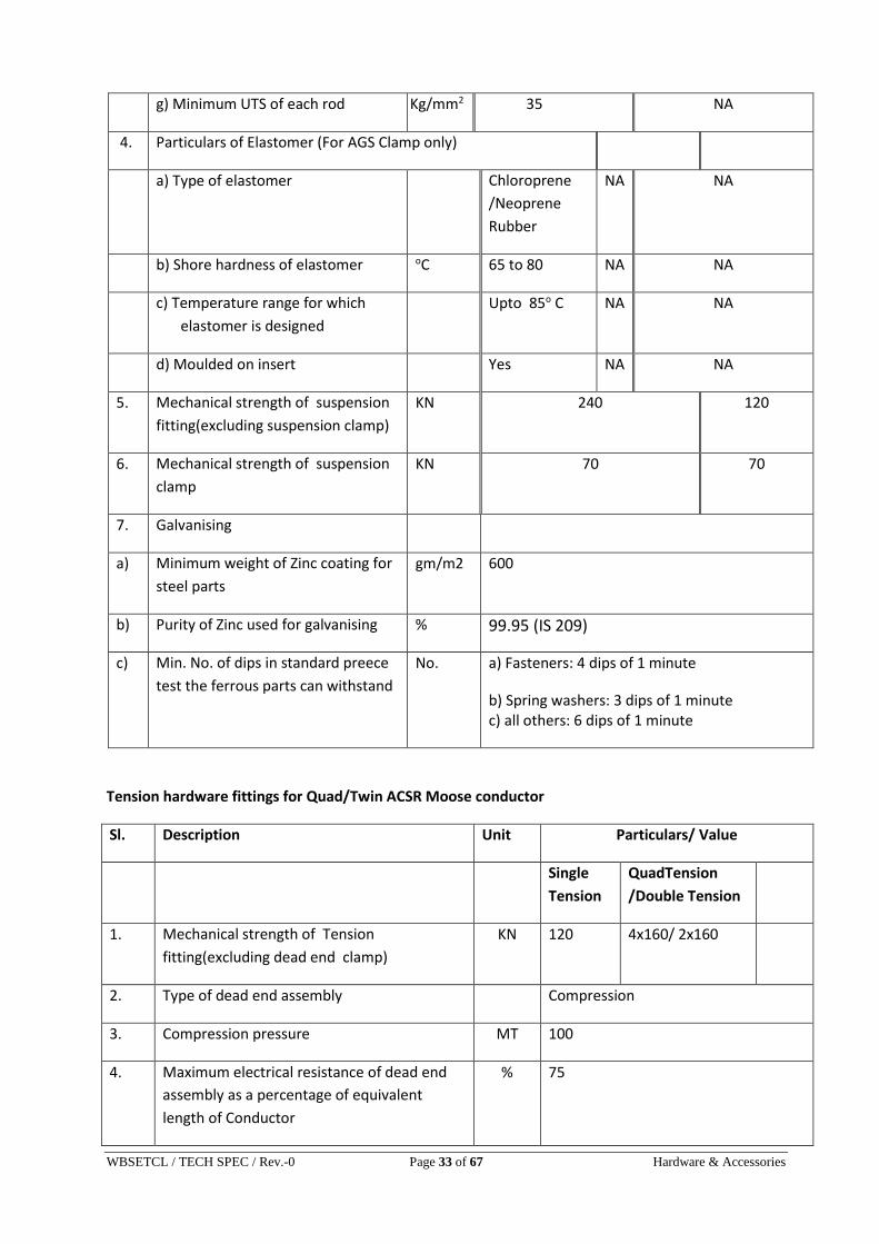
g) Minimum UTS of each rod Kg/mm2 35 NA
4. Particulars of Elastomer (For AGS Clamp only)
a) Type of elastomer Chloroprene
/Neoprene
Rubber
NA NA
b) Shore hardness of elastomer oC 65 to 80 NA NA
c) Temperature range for which
elastomer is designed
Upto 85o C NA NA
d) Moulded on insert Yes NA NA
5. Mechanical strength of suspension
fitting(excluding suspension clamp)
KN 240 120
6. Mechanical strength of suspension
clamp
KN 70 70
7. Galvanising
a) Minimum weight of Zinc coating for
steel parts
gm/m2 600
b) Purity of Zinc used for galvanising % 99.95 (IS 209)
c) Min. No. of dips in standard preece
test the ferrous parts can withstand
No. a) Fasteners: 4 dips of 1 minute
b) Spring washers: 3 dips of 1 minute c) all others: 6 dips of 1 minute
Tension hardware fittings for Quad/Twin ACSR Moose conductor
Sl. Description Unit Particulars/ Value
Single
Tension
QuadTension
/Double Tension
1. Mechanical strength of Tension
fitting(excluding dead end clamp)
KN 120 4x160/ 2x160
2. Type of dead end assembly Compression
3. Compression pressure MT 100
4. Maximum electrical resistance of dead end
assembly as a percentage of equivalent
length of Conductor
% 75
WBSETCL / TECH SPEC / Rev.-0 Page 34 of 67 Hardware & Accessories
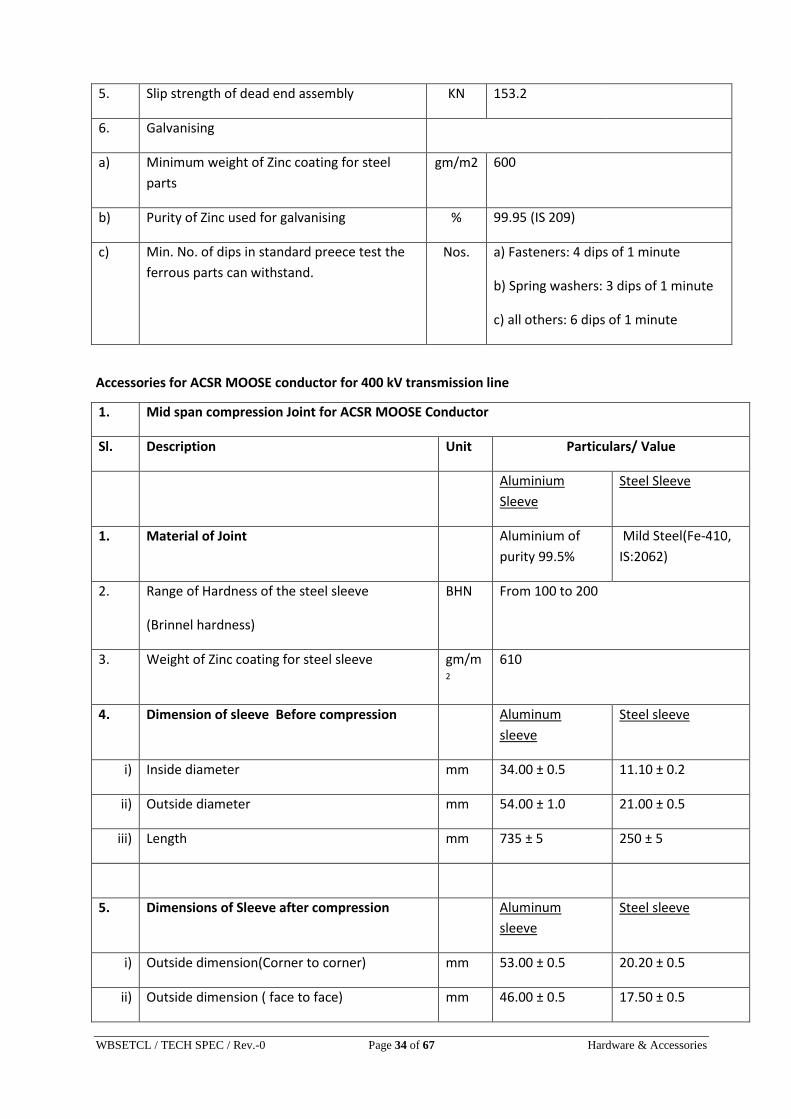
5. Slip strength of dead end assembly KN 153.2
6. Galvanising
a) Minimum weight of Zinc coating for steel
parts
gm/m2 600
b) Purity of Zinc used for galvanising % 99.95 (IS 209)
c) Min. No. of dips in standard preece test the
ferrous parts can withstand.
Nos. a) Fasteners: 4 dips of 1 minute
b) Spring washers: 3 dips of 1 minute
c) all others: 6 dips of 1 minute
Accessories for ACSR MOOSE conductor for 400 kV transmission line
1. Mid span compression Joint for ACSR MOOSE Conductor
Sl. Description Unit Particulars/ Value
Aluminium
Sleeve
Steel Sleeve
1. Material of Joint Aluminium of
purity 99.5%
Mild Steel(Fe-410,
IS:2062)
2. Range of Hardness of the steel sleeve
(Brinnel hardness)
BHN From 100 to 200
3. Weight of Zinc coating for steel sleeve gm/m2
610
4. Dimension of sleeve Before compression Aluminum
sleeve
Steel sleeve
i) Inside diameter mm 34.00 ± 0.5 11.10 ± 0.2
ii) Outside diameter mm 54.00 ± 1.0 21.00 ± 0.5
iii) Length mm 735 ± 5 250 ± 5
5. Dimensions of Sleeve after compression Aluminum
sleeve
Steel sleeve
i) Outside dimension(Corner to corner) mm 53.00 ± 0.5 20.20 ± 0.5
ii) Outside dimension ( face to face) mm 46.00 ± 0.5 17.50 ± 0.5

WBSETCL / TECH SPEC / Rev.-0 Page 35 of 67 Hardware & Accessories
iii) Length mm 785 (approx) 286 (approx)
6. Slip strength KN 153.2
7. Maximum resistance of the compressed unit
expressed, as percentage of the resistance of
equivalent length of bare conductor.
% 75
8. Minimum corona Extinction voltage kV (rms)
under dry condition
kV 320
9. Maximum Radio Interference Voltage at 1
MHz for phase to earth voltage of 305 kV
(rms) under dry condition
Micro
Volts
1000
Repair sleeve for ACSR MOOSE Conductor
Sl. Description Unit Particulars/ Value
1. Material Aluminium of minimum purity 99.5%
2. Dimension of Aluminum sleeve Before compression
i) Inside diameter mm 34.00 ± 0.5
ii) Outside diameter mm 54.00 ± 1.0
iii) Length mm 300.00 ± 5.0
3. Dimensions of Aluminum Sleeve after compression
i) Outside dimension(Corner to corner) mm 53.00 ± 0.5
ii) Outside dimension (face to face) mm 46.00 ± 0.5
iii) Length mm 330.00(Approx.)
4. Minimum corona Extinction voltage kV
(rms) under dry condition
kV 320
5. Maximum Radio Interference Voltage at 1
MHz for phase to earth voltage of 305 kV
(rms) under dry condition
Micro
Volts
1000
WBSETCL / TECH SPEC / Rev.-0 Page 36 of 67 Hardware & Accessories
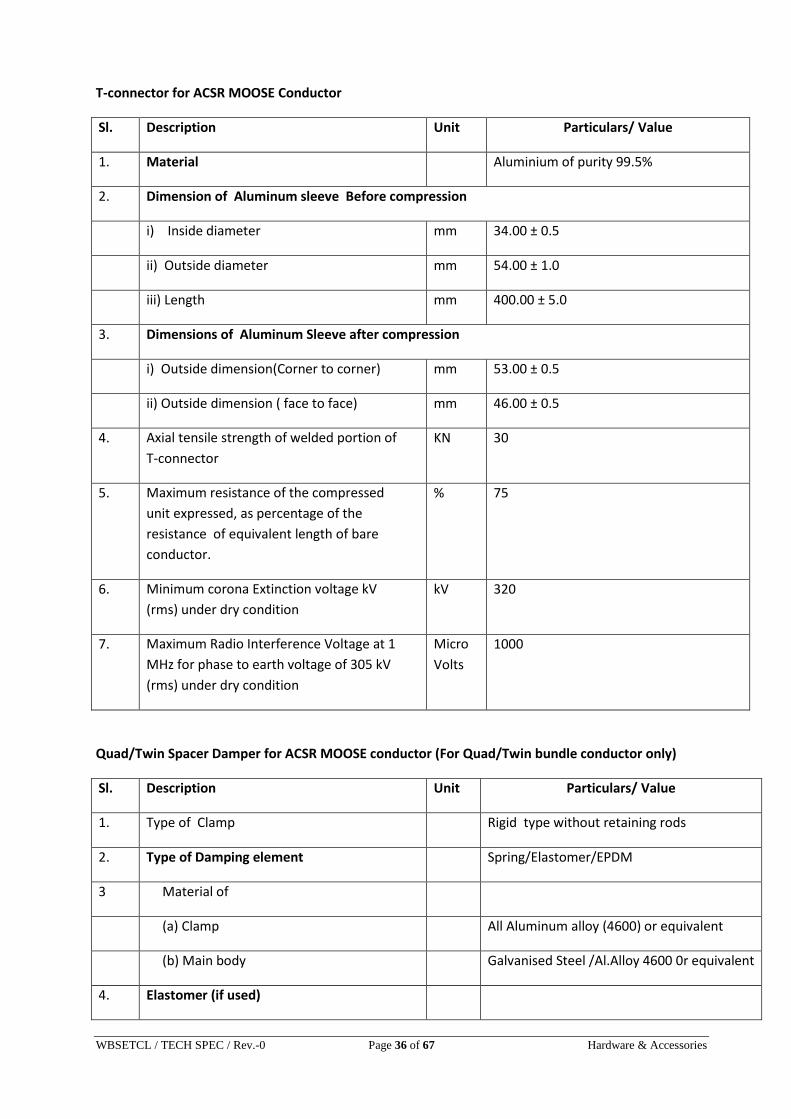
T-connector for ACSR MOOSE Conductor
Sl. Description Unit Particulars/ Value
1. Material Aluminium of purity 99.5%
2. Dimension of Aluminum sleeve Before compression
i) Inside diameter mm 34.00 ± 0.5
ii) Outside diameter mm 54.00 ± 1.0
iii) Length mm 400.00 ± 5.0
3. Dimensions of Aluminum Sleeve after compression
i) Outside dimension(Corner to corner) mm 53.00 ± 0.5
ii) Outside dimension ( face to face) mm 46.00 ± 0.5
4. Axial tensile strength of welded portion of
T-connector
KN 30
5. Maximum resistance of the compressed
unit expressed, as percentage of the
resistance of equivalent length of bare
conductor.
% 75
6. Minimum corona Extinction voltage kV
(rms) under dry condition
kV 320
7. Maximum Radio Interference Voltage at 1
MHz for phase to earth voltage of 305 kV
(rms) under dry condition
Micro
Volts
1000
Quad/Twin Spacer Damper for ACSR MOOSE conductor (For Quad/Twin bundle conductor only)
Sl. Description Unit Particulars/ Value
1. Type of Clamp Rigid type without retaining rods
2. Type of Damping element Spring/Elastomer/EPDM
3 Material of
(a) Clamp All Aluminum alloy (4600) or equivalent
(b) Main body Galvanised Steel /Al.Alloy 4600 0r equivalent
4. Elastomer (if used)

WBSETCL / TECH SPEC / Rev.-0 Page 37 of 67 Hardware & Accessories
(a) Shore hardness Die-casting
(b) Temp.range for which designed 0C Upto 850C
5.
Minimum ultimate tensile strength of
spacer
(a) Compressive load kN 14
(b) Tensile load kN 7.0
6. Slipping strength of spacer clamp
a)Before vibration test
Clamp
Type
Longitudin
al load(KN)
Maxm. Slip
permitted(mm)
Metal-
Metal
Bolted
6.5 1
Rubber
loaded
2.5 2.5
Preforme
d rods
2.5 12
b)After Vibration test KN 80% of the above values
6. Maximum Magnetic power loss per spacer
for 600 Amps, 50 Hz Alternating Current Watts Below 1 watt
7. Minimum corona Extinction voltage kV
(rms) under dry condition
kV 320
8. Maximum Radio Interference Voltage (RIV)
at 1 MHz for phase to earth voltage of 305
kV (rms) under dry condition
Micro
volts
1000
Rigid Spacer for Jumper for ACSR MOOSE conductor (For Quad/Twin bundle conductor only)
Sl. Description Unit Particulars/ Value
1. Type of Spacer Rigid type without retaining rods
2. Material of component parts
(a) Clamp Aluminum alloy (4600)
(b) Main body Aluminum alloy 6063/63400 ;
6061/65032

WBSETCL / TECH SPEC / Rev.-0 Page 38 of 67 Hardware & Accessories
3. Manufacturing process of component parts
(a) Clamp Die-casting
(b) Main body Aluminum extrusion
4.
Minimum ultimate tensile strength of
spacer
(a) Compressive load kN 14
(b) Tensile load kN 7.0
5. Slipping strength of spacer clamp kN 2.5
6. Maximum Magnetic power loss per spacer
for 600 Amps, 50 Hz Alternating Current Watts 1
7. Minimum corona Extinction voltage kV
(rms) under dry condition
kV 320
8. Maximum Radio Interference Voltage (RIV)
at 1 MHz for phase to earth voltage of 305
kV (rms) under dry condition
Micro
volts
1000
Mid span compression Joint for 7/3.66 mm GS Earthwire
Sl. Description Unit Particulars/ Value
Aluminium / Filler
Sleeve
Steel Sleeve
1. Material of Joint Aluminium of minimum
purity 99.5%
Mild Steel(Fe-
410, IS:2062)
2. Range of Hardness of the steel sleeve
(Brinnel hardness)
BHN From 100 to 200
3. Weight of Zinc coating gm/m2
600
4. Dimension of sleeve Before compression
Aluminiu
m Sleeve
Steel
Sleeve
Alu filler sleeve

WBSETCL / TECH SPEC / Rev.-0 Page 39 of 67 Hardware & Accessories
i) Inside diameter mm 22.00 ±
0.5
11.50 ± 0.2 11.50 ± 0.2
ii) Outside diameter mm 32.00 ±
0.5
21.00 ± 0.5 21.00 ± 0.5
iii) Length mm 400 ± 5 230 ± 5 60 ± 5
5. Dimensions of Sleeve after compression
Aluminium Sleeve Steel Sleeve
i) Outside dimension(Corner to Corner) mm 29.40 ± 0.5 20.20 ± 0.5
ii) Outside dimension (face to face) mm 25.00 ± 0.5 17.50 ± 0.5
iii) Length mm 430 (approx) 265 (approx)
6. Slip strength KN 65
7. Maximum resistance of the compressed
unit expressed, as percentage of the
resistance of equivalent length of bare
Earthwire
% 75
Flexible Copper Bond for 7/3.66 mm GS Earthwire
Sl. Description Unit Particulars/ Value
1. Stranding 37/7/0.417
2. Cross sectional area Sq.mm 35.4
3. Minimum copper equivalent area Sq.mm 34
4. Length of copper cable mm 500 + 5
5. Material of lugs Tinned copper
6. Bolt Size
i) Diameter mm 16
ii) Length mm 40

WBSETCL / TECH SPEC / Rev.-0 Page 40 of 67 Hardware & Accessories
Vibration Damper for 7/3.66 mm GS Earthwire
Sl. Description Unit Particulars/ Value
1. Type of Damper 4R-Stockbridge type
2. Materials of components
a) Damper masses Cast iron/mild steel/Zinc alloy duly hop
dip galvanised
b) Clamp Aluminum alloy 4600
c) Messenger cable High tensile strength galvanized steel
3. Number of strands in stranded messenger
cable
Nos. 19
4. Minimum ultimate tensile strength of
stranded messenger cable
Kg/mm2 135
5. Slip strength of stranded messenger cable
(mass pull off)
kN 2.5
6. Slipping strength of damper clamp
(a) Before fatigue test kN 2.5
(b) After fatigue test kN 2
7. Resonance frequencies range Hz 10 to 60
8. Percentage variation in reactance after
fatigue test in comparison with that . before
fatigue test
% +/-40 (Maximum)
9. Percentage variation in power dissipation
after fatigue test in comparison with that
before fatigue test
% +/-40 (Maximum)
Suspension Clamp for 7/3.66 mm GS Earthwire
Sl. Description Unit Particulars/ Value
1. Material of components
(a) Shackle Forged Steel
(b) Clamp Body & Keeper Malleable cast iron / SGI
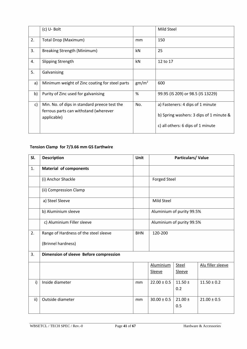
WBSETCL / TECH SPEC / Rev.-0 Page 41 of 67 Hardware & Accessories
(c) U- Bolt Mild Steel
2. Total Drop (Maximum) mm 150
3. Breaking Strength (Minimum) kN 25
4. Slipping Strength kN 12 to 17
5. Galvanising
a) Minimum weight of Zinc coating for steel parts gm/m2 600
b) Purity of Zinc used for galvanising % 99.95 (IS 209) or 98.5 (IS 13229)
c) Min. No. of dips in standard preece test the
ferrous parts can withstand (wherever
applicable)
No. a) Fasteners: 4 dips of 1 minute
b) Spring washers: 3 dips of 1 minute &
c) all others: 6 dips of 1 minute
Tension Clamp for 7/3.66 mm GS Earthwire
Sl. Description Unit Particulars/ Value
1. Material of components
(i) Anchor Shackle Forged Steel
(ii) Compression Clamp
a) Steel Sleeve Mild Steel
b) Aluminium sleeve Aluminium of purity 99.5%
c) Aluminium Filler sleeve Aluminium of purity 99.5%
2. Range of Hardness of the steel sleeve
(Brinnel hardness)
BHN 120-200
3. Dimension of sleeve Before compression
Aluminium
Sleeve
Steel
Sleeve
Alu filler sleeve
i) Inside diameter mm 22.00 ± 0.5 11.50 ±
0.2
11.50 ± 0.2
ii) Outside diameter mm 30.00 ± 0.5 21.00 ±
0.5
21.00 ± 0.5

WBSETCL / TECH SPEC / Rev.-0 Page 42 of 67 Hardware & Accessories
iii) Length mm 245 ± 5 205 ± 5 25 .0
4. Dimensions of Sleeve after compression
Aluminium Sleeve Steel Sleeve
i) Outside dimension(Corner to Corner) mm 29.40 ± 0.5 20.20 ± 0.5
ii) Outside dimension (face to face) mm 25.00 ± 0.5 17.50 ± 0.5
5. Slip strength KN 65
6. Minimum Breaking strength of assembly
(excluding clamp)
KN 70
7. Compression Pressure Ton 100
8. Galvanising
a) Minimum weight of Zinc coating for steel parts gm/
m2
600
b) Purity of Zinc used for galvanising % 99.95 (IS 209) or 98.5 (IS 13229)
c) Min. No. of dips in standard preece test the
ferrous parts can withstand (wherever
applicable)
No. a) Fasteners: 4 dips of 1 minute
b) Spring washers: 3 dips of 1 minute &
c) all others: 6 dips of 1 minute

WBSETCL / TECH SPEC / Rev.-0 Page 43 of 67 Hardware & Accessories
ANNEXURE - A
1.0 Tests on Complete Strings with Hardware Fittings
1.1 Voltage Distribution Test (For Insulator String with Disc Insulators)
The voltage across each insulator unit shall be measured by sphere gap method. The result
obtained shall be converted into percentage. The voltage across any disc shall not exceed
following percentage value for different voltage level lines:-
SL. NO. VOLTAGE LEVEL OF
LINE
SUSPENSION STRING TENSION STRING
1 400 kV 9.0 % 10.0 %
1.2 Vibration Test
The suspension string shall be tested in suspension mode, and tension string in tension
mode itself in laboratory span of minimum 30 meters. In the case of suspension string a
load equal to 600 kg shall be applied along the axis of the suspension string by means of
turn buckle. The insulator string along with hardware fittings and no. of sub conductors and
tension in each sub conductor secured them with clamps shall be as mentioned in the table
below.
NO. VOLTAGE
LEVEL OF
LINE
NAME OF
CONDUCTOR
NO. OF SUB-
CONDUCTOR
TENSION OF EACH
SUB-CONDUCTOR
1. 400 kV ACSR MOOSE 4/2 43KN
The system shall be suitable to maintain constant tension on each sub-conductors
throughout the duration of the test. Vibration dampers shall not be used on the test span.
Both the sub-conductors shall be vertically vibrated simultaneously at one of the resonance
frequencies of the insulators string (more than 10 Hz) by means of vibration inducing
equipment. The peak to peak displacement in mm of vibration at the antinode point nearest
to the string shall be measured and the same shall not be less than 1000/f18 where f is the
frequency of vibration in cycles/sec. The insulator string shall be vibrated for not less than
10 million cycles without any failure. After the test the disc insulators shall be examined for
looseness of pins and cap or any crack in the cement. The hardware shall be examined for
looseness, fatigue failure and mechanical strength test. There shall be no deterioration of
properties of hardware components and disc insulators after the vibration test. The disc
insulators shall be subjected to the following, tests as per relevant standards :
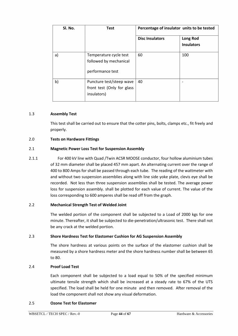
WBSETCL / TECH SPEC / Rev.-0 Page 44 of 67 Hardware & Accessories
Sl. No. Test Percentage of insulator units to be tested
Disc Insulators Long Rod
Insulators
a) Temperature cycle test
followed by mechanical
performance test
60 100
b) Puncture test/steep wave
front test (Only for glass
insulators)
40 -
1.3 Assembly Test
This test shall be carried out to ensure that the cotter pins, bolts, clamps etc., fit freely and
properly.
2.0 Tests on Hardware Fittings
2.1 Magnetic Power Loss Test for Suspension Assembly
2.1.1 For 400 kV line with Quad /Twin ACSR MOOSE conductor, four hollow aluminium tubes
of 32 mm diameter shall be placed 457 mm apart. An alternating current over the range of
400 to 800 Amps for shall be passed through each tube. The reading of the wattmeter with
and without two suspension assemblies along with line side yoke plate, clevis eye shall be
recorded. Not less than three suspension assemblies shall be tested. The average power
loss for suspension assembly. shall be plotted for each value of current. The value of the
loss corresponding to 600 amperes shall be read off from the graph.
2.2 Mechanical Strength Test of Welded Joint
The welded portion of the component shall be subjected to a Load of 2000 kgs for one
minute. Thereafter, it shall be subjected to die-penetration/ultrasonic test. There shall not
be any crack at the welded portion.
2.3 Shore Hardness Test for Elastomer Cushion for AG Suspension Assembly
The shore hardness at various points on the surface of the elastomer cushion shall be
measured by a shore hardness meter and the shore hardness number shall be between 65
to 80.
2.4 Proof Load Test
Each component shall be subjected to a load equal to 50% of the specified minimum
ultimate tensile strength which shall be increased at a steady rate to 67% of the UTS
specified. The load shall be held for one minute and then removed. After removal of the
load the component shall not show any visual deformation.
2.5 Ozone Test for Elastomer
WBSETCL / TECH SPEC / Rev.-0 Page 45 of 67 Hardware & Accessories
This test shall be performed in accordance with ASTM D-1171 by the Ozone chamber
exposure method (method B). The test duration shall be 500 hours and the ozone
concentration 50 PPHM. At the test completion, there shall be no visible crack under a 2 x
magnification.
3.0 Tests on Conductor and Earth wire Accessories
3.1 Flexible Copper Bond for earthwire
Slip Strength Test
On applying a load of 3 KN between the two ends, stranded flexible copper cable shall not
come out of the connecting lugs and none of its strands shall be damaged. After the test,
the lugs shall be cut open to ascertain that the gripping of cable has not been affected.
3.2 Vibration Damper for conductor and earth wire
(a) Dynamic Characteristics, Test
The damper shall be mounted with its clamp tightened with torque recommended by the
manufacturer on shaker table capable of simulating sinusoidal vibrations for aeolian
vibration frequency band range as per table 3.4 for vibration damper for different type of
conductor/earthwire. The damper assembly shall be vibrated vertically with a + 1 mm
amplitude from 5 to 15 Hz frequency and beyond 15 Hz at ± 0.5mm to determine following
characteristics with the help of suitable recording instruments:
(i) Force Vs frequency
(ii) Phase angle Vs frequency
(iii) Power dissipation Vs frequency
The Force Vs frequency curve shall not show steep peaks at resonance frequencies and deep
troughs between the resonance frequencies. The resonance frequencies shall be suitably
spread within the aeolian vibration frequency-band between the lower and upper
dangerous frequency, limits determined by the vibration analysis of conductor/earth wire
without dampers.
Acceptance criteria for vibration damper.
(i) The above dynamic characteristics test on five damper shall be conducted.
(ii) The mean reactance and phase angle Vs frequency curves shall be drawn with the
criteria of best fit method.
(iii) The above mean reactance response curve should lie within limits as per table 3.4.
(iv) The above mean phase angle response curve shall be between 25o to 130o within
the frequency range of interest.
(v) If the above curve lies within the envelope, the damper design shall be considered
to have successfully met the requirement.
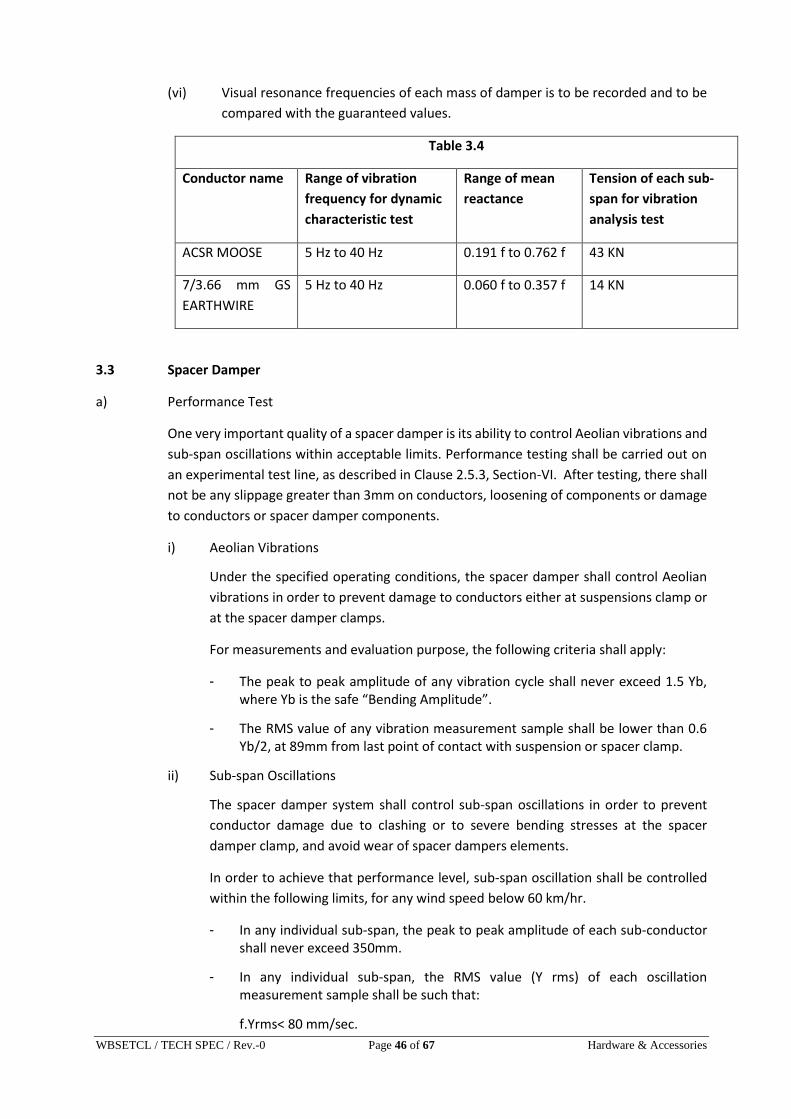
WBSETCL / TECH SPEC / Rev.-0 Page 46 of 67 Hardware & Accessories
(vi) Visual resonance frequencies of each mass of damper is to be recorded and to be
compared with the guaranteed values.
Table 3.4
Conductor name Range of vibration
frequency for dynamic
characteristic test
Range of mean
reactance
Tension of each sub-
span for vibration
analysis test
ACSR MOOSE 5 Hz to 40 Hz 0.191 f to 0.762 f 43 KN
7/3.66 mm GS
EARTHWIRE
5 Hz to 40 Hz 0.060 f to 0.357 f 14 KN
3.3 Spacer Damper
a) Performance Test
One very important quality of a spacer damper is its ability to control Aeolian vibrations and
sub-span oscillations within acceptable limits. Performance testing shall be carried out on
an experimental test line, as described in Clause 2.5.3, Section-VI. After testing, there shall
not be any slippage greater than 3mm on conductors, loosening of components or damage
to conductors or spacer damper components.
i) Aeolian Vibrations
Under the specified operating conditions, the spacer damper shall control Aeolian
vibrations in order to prevent damage to conductors either at suspensions clamp or
at the spacer damper clamps.
For measurements and evaluation purpose, the following criteria shall apply:
- The peak to peak amplitude of any vibration cycle shall never exceed 1.5 Yb, where Yb is the safe “Bending Amplitude”.
- The RMS value of any vibration measurement sample shall be lower than 0.6 Yb/2, at 89mm from last point of contact with suspension or spacer clamp.
ii) Sub-span Oscillations
The spacer damper system shall control sub-span oscillations in order to prevent
conductor damage due to clashing or to severe bending stresses at the spacer
damper clamp, and avoid wear of spacer dampers elements.
In order to achieve that performance level, sub-span oscillation shall be controlled
within the following limits, for any wind speed below 60 km/hr.
- In any individual sub-span, the peak to peak amplitude of each sub-conductor shall never exceed 350mm.
- In any individual sub-span, the RMS value (Y rms) of each oscillation measurement sample shall be such that:
f.Yrms< 80 mm/sec.

WBSETCL / TECH SPEC / Rev.-0 Page 47 of 67 Hardware & Accessories
Where
Y (rms) = anti node amplitude (mm)
f = frequency of the oscillation (cycle/sec.)
f = (1/2L) sqrt (T/m)
L = sub-span length (m)
T = Conductor tension (N)
m = conductor mass (kg/m)
For any set of 10 or more measurement samples associated with a given wind
sector and a given sub-span, the Y rms value shall be such that:
f. Yrms<70 mm/sec.
The wind sector is defined as a combination of 5 km/hr wind speed range and
10º wind direction range.
Each measurement sample shall be at least one (1) minute long.
b) Clamp Slip Test (for spacer for jumper also)
The spacer damper assembly shall be installed on a four conductors bundle string at a
tension of 39 kN. In case of spacer for jumper, the clamp of sample shall be tightened with
a specified tightening torque. One of the sample clamps, when subjected to a longitudinal
pull parallel to the conductor axis for a minimum duration of one minute, shall not slip on
the conductor, i.e. the permanent displacement between the conductor and the clamp of
the sample measured after removal of the load shall not exceed specified values. The
minimum slip under longitudinal pull varies with clamp type according to the following
table.
CLAMP TYPE LONGITUDINAL
LOAD (kN)
MAXIMUM
SLIP(mm)
Metal-Metal bolted 6.5 1
Rubber loaded
Clamp using
2.5 2.5
Preformed rods 2.5 12
In order to determine the effect of conductor creep with the spacer dampers only, the
conductor shall be re-tensioned to 68 kN without further tightening the spacer damper
clamps and the clamp slip test shall be re-performed. The minimum slip under longitudinal
loads shall not be less than 80% of the values given in the above table.

WBSETCL / TECH SPEC / Rev.-0 Page 48 of 67 Hardware & Accessories
Similar testing shall be performed of the other clamps of the same sample. For spacer
dampers only, such clamp slip tests shall also be conducted after each of the vibration tests
mentioned in Clause 3.5 (a) but under longitudinal loading corresponding to 80% of the
values given in the above table.
c) Dynamic Characteristic Test for Spacer Damper
The purpose of this test is to obtain quantitative information regarding the dynamic
characteristic of the spacer damper. The values obtained during this test will serve as
references to evaluate the behaviour of the same spacer damper under the fatigue test.
The test will consist in the application of sinusoidal movement to the spacer damper
articulation and measurement of the force (F), displacement (X) and phase angle (Ø)
between these two. From these values, the stiffness (K) and damping faction (n) shall be
calculated as:
The test frequency shall not be higher than 3 Hz. The test shall be performed at five
different displacement amplitudes. The amplitudes shall be selected to reproduce 10, 20,
40, 60 and 90 percent of the maximum displacement permitted by the spacer damper
design.
The test shall be performed on three samples.
In case of spacer dampers with a single articulation for each arm, the central body shall be
applied between two arms corresponding to a horizontal pair of conductors. In this case,
one spacer clamp may be fixed and the other displaced in its direction, the central body
being free to move.
d) Fatigue Test for Spacer Damper
The purpose of this test is to evaluate the capacity of the spacer damper to sustain without
damage the cyclic movements which can be induced by vibrations.
The spacer damper articulation shall be subjected to cyclic motions for a total of 10 million
cycles. The test frequency shall be between 2 and 3 Hz. The amplitude of motion shall be
established on the following basis:
- the load applied on the spacer damper clamp shall not be less than 300N;
- The clamp displacement under the applied load shall not be less than 60% of the maximum displacement permitted by the design;
- If the 300 N load generates movement exceeding the maximum permitted displacement, the load can be reduced to limit the movement to 95% of the maximum displacement.
After the test, the sample shall be subjected to a second dynamic characteristic test. The
test shall be performed at two amplitudes, 10% and 60% of the maximum displacement.
The spacer damper shall show no signs of cracks or detoriation, loosening of bolts or
abnormal wear.
The dynamic characteristics (k and n) shall not be less than 75% of the values measured
before the fatigue test. The test shall be performed on three samples which have been
WBSETCL / TECH SPEC / Rev.-0 Page 49 of 67 Hardware & Accessories
previously subjected to dynamic characteristics test. Motion shall be as described in
Dynamic Characteristic Test.
e) Ozone Test This test shall be performed on elastomer/rubber components in accordance with ASTM D-
1171 by the ozone chamber exposure method (Method-B). The test durations hall be 500
hours and the ozone concentration 50 PPHM. At the test completion, there shall be no
visible crack under a 2 x magnification.
f) Compression and Tensile Tests Three samples of spacer dampers shall be subjected to a tension compression test. The
load shall be applied between each pair of diagonally opposed conductors. Under the
compressive load, the arms shall be allowed to rotate until they reach their mechanical
stops. A compressive load of 15 kN shall first be applied and held for five minutes. Then a
tensile load of 5 kN shall be applied on the same pair of arms. The test shall be repeated on
the other pair of arms. After the test, the spacer damper must be dismantled and the
components examined. There should not be any failure of components or damage
impairing the reusability of the spacer damper such as permanent deformation. The spacer
geometry shall be maintained within 5% of the original dimensions.
3.4 Magnetic Power Loss Test for Spacer Damper/Spacer for jumper
The sample involving ferrous parts shall be tested in a manner to simulate service conditions
for 50 Hz pure sine-wave. The test should be carried out at various currents ranging from
400 amperes to 800 amperes for 400 kV line and the magnetic power loss at various currents
should be specified in tabulated graphical form. The difference between the power losses
without and with sample at room temperature shall be limited to 1 watt for 600 amperes
current (rms) for ACSR MOOSE Conductor. The losses shall be determined by averaging the
observations obtained from at least four samples.
3.5 Mechanical Strength Test for Earthwire Suspension/Tension Clamp
(a) The suspension assembly/tension assembly (excluding tension clamp) shall be
subjected to a load equal to 50% of the specified minimum ultimate tensile strength
(UTS) which shall be increased at a steady rate to 67% of the minimum UTS specified.
This load shall be held for five minutes and then removed. After removal of the load,
the components shall not show any visual deformation and it shall be possible to
disassemble them by hand. Hand tools may be used to loosen the nuts initially. The
assembly shall then be reassembled and loaded to 50% of UTS and the load shall be
further increased at a steady rate till the specified minimum UTS is reached and held
for one minute. No fracture should occur during this period. The applied load shall then
be increased until the failing load is reached and the value recorded.
(b) Clamp Slip Strength Vs Torque Test for Suspension Assembly
The suspension assembly shall be vertically suspended by means of a flexible
attachment. A suitable length of Earthwire shall be fixed in the clamps. The clamp slip
strength at various tightening torques shall be obtained by gradually applying the load
at one end of the earthwire. The clamp slip strength Vs torque curve shall be drawn.
The clamp slip strength at the recommended tightening torque shall be more than 12
WBSETCL / TECH SPEC / Rev.-0 Page 50 of 67 Hardware & Accessories
kN but less than 17 kN for 7/3.66 mm earthwireand more than 9 kN but less than 14
kN for 7/3.15 mm earthwire.
(c) Slip Strength Test of Tension Clamp
Tension clamps shall be compressed on a 5 m length of earthwire on both ends. The
assembly shall be mounted on a tensile testing machine and anchored in a manner
similar to the arrangement to be used in service. A tensile load of 50% of the specified
breaking load of the earthwire shall be applied & the sample shall be marked in such a
way that movement relative to the fitting can easily be detected. Without any
subsequent adjustment of the fitting, the load shall be steadily increased to 95% of the
specified breaking load and maintained for one minute. There shall be no movement
of the earthwire relative to the fitting during this one minute period and no failure of
the fitting also.
(d) Electrical Resistance Test of Tension Clamp
The tension clamp and the jumper shall be compressed on two suitable lengths of
earthwire. The electrical resistance shall be measured between points on earthwire
near the clamp and near the jumper mouth keeping 25 mm clearance of the fitting and
should not exceed 75% of the measured resistance of equivalent length of earthwire.
The test shall be conducted with direct current. The current connections shall be at a
distance not less than 50 times the diameter of earthwire from the fitting and shall be
made so that effective contact is ensured with all those strands of the earth wire which
would be taken into account in calculating its equivalent resistance. The test shall be
repeated with the polarity reversed and the average of the two results considered as
the measured value.
3.6 Corona Extinction Voltage Test (Dry)
The sample when subjected to power frequency voltage shall have a corona extinction
voltage 320 kV (rms) line to ground for 400 kV lines under dry condition for 400 kV line.
There shall be no evidence of corona on any part of the sample. The atmospheric condition
during testing shall be recorded and the test results shall be accordingly corrected with
suitable correction factor as stipulated in IS:731.
3.7 Radio Interference Voltage Test (Dry)
Under the conditions as specified under (3.8) above, the sample shall have a radio
interference voltage level below 1000 micro volts at one MHz when subjected to 50 Hz AC
voltage of 305 kV rms line to ground under dry condition for 400 kV line. The test procedure
shall be in accordance with IS 8263.
3.8 Chemical Analysis Test
Chemical analysis of the material used for manufacture of items shall be conducted to check
the conformity of the same with Technical Specification and approved drawing.

WBSETCL / TECH SPEC / Rev.-0 Page 51 of 67 Hardware & Accessories
4.0 Tests on All components (As applicable)
4.1 Chemical Analysis of Zinc used for Galvanizing
Samples taken from the zinc ingot shall be chemically analysed as per IS-209-1979. The
purity of zinc shall not be less than 99.95%.
4.2 Tests for Forgings
The chemical analysis hardness tests and magnetic particle inspection for forgings, will be
as per the internationally recognized procedures for these tests. The, sampling will be
based on heat number and heat treatment batch. The details regarding test will be as
discussed and mutually agreed to by the Contractor and Purchaser in Quality Assurance
Programme.
4.3 Tests on Castings
The chemical analysis, mechanical and metallographic tests and magnetic particle
inspection for castings will be as per the internationally recognised procedures for these
tests. The samplings will be based on heat number and heat treatment batch. The details
regarding test will be as discussed and mutually agreed to by the Contractor and Purchaser
in Quality Assurance Programme.

WBSETCL / TECH SPEC / Rev.-0 Page 52 of 67 Hardware & Accessories
GUARANTEED TECHNICAL PARTICULARS
(To be filled in and signed by the Bidder)
A. MIDSPAN COMPRESSION JOINT FOR CONDUCTOR:
1. Maker’s name & country :
2. Type :
3. Suitable for (conductor size) :
4. Outside diameter of sleeves (mm) :
Before compression:
i) Aluminium :
ii)Steel :
:
After compression:
i) Aluminium :
ii)Steel :
:
5. Length of sleeves:
Before compression:
i) Aluminium :
ii)Steel :
iii)Aluminium Alloy :
After compression:
i) Aluminium :
ii) Steel :
iii) Aluminium Alloy :
6. Weight of sleeves
i) Aluminium (Kg) :
ii)Steel (Kg) :
iii)Total (Kg) :

WBSETCL / TECH SPEC / Rev.-0 Page 53 of 67 Hardware & Accessories
7. Slipping strength of Midspan joint
Expressed as percentage of ultimate
Tensile strength of conductor (%) :
8. Breaking strength of Midspan joint
Expressed as percentage of ultimate
Tensile strength of conductor(%) :
9. Conductivity of the compression
Joint expressed as percentage of the
Conductivity of the conductor (%) :
10. Resistance of percentage of measured
Resistance of equivalent length of
Conductor (%) :
11. Corona Extinction voltage on the joint:
i) Dry condition :
ii)Wet condition :
12. Full details of the Hydraulic
Compressor and die sets :
13. Packing details (number of joint
Assemblies per packages and Gross
Weight) in Kg :
14. Standard to which conforming :
15. Galvanising on Ferrous
i) Minimum weight of zinc
coating (gm/m2) :
ii) Number of dip per minute :
16. RIV performance of joint at 1(one)
MHz :
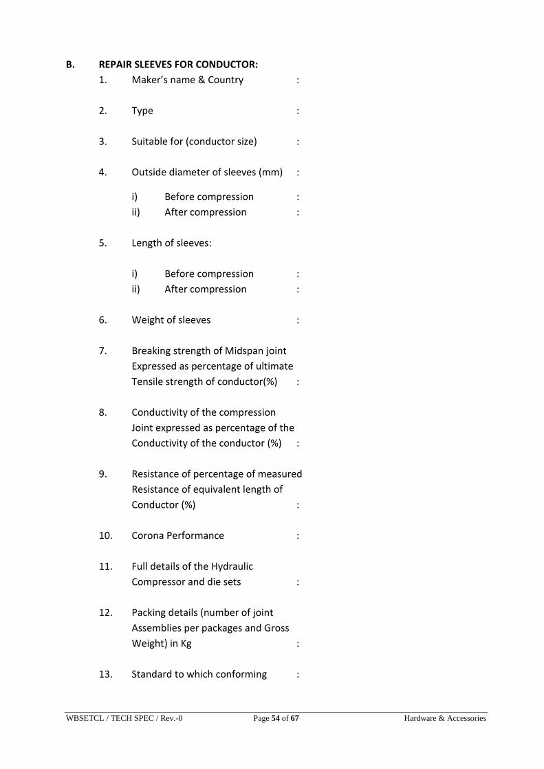
WBSETCL / TECH SPEC / Rev.-0 Page 54 of 67 Hardware & Accessories
B. REPAIR SLEEVES FOR CONDUCTOR:
1. Maker’s name & Country :
2. Type :
3. Suitable for (conductor size) :
4. Outside diameter of sleeves (mm) :
i) Before compression :
ii) After compression :
5. Length of sleeves:
i) Before compression :
ii) After compression :
6. Weight of sleeves :
7. Breaking strength of Midspan joint
Expressed as percentage of ultimate
Tensile strength of conductor(%) :
8. Conductivity of the compression
Joint expressed as percentage of the
Conductivity of the conductor (%) :
9. Resistance of percentage of measured
Resistance of equivalent length of
Conductor (%) :
10. Corona Performance :
11. Full details of the Hydraulic
Compressor and die sets :
12. Packing details (number of joint
Assemblies per packages and Gross
Weight) in Kg :
13. Standard to which conforming :
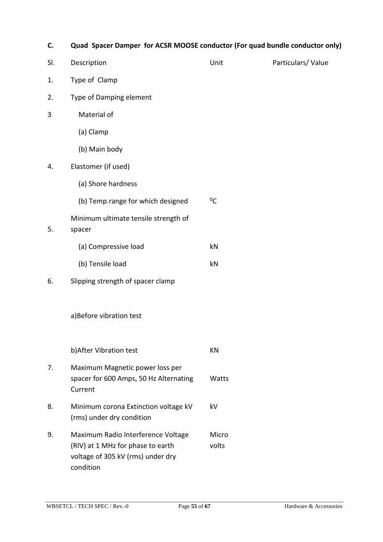
WBSETCL / TECH SPEC / Rev.-0 Page 55 of 67 Hardware & Accessories
C. Quad Spacer Damper for ACSR MOOSE conductor (For quad bundle conductor only)
Sl. Description Unit Particulars/ Value
1. Type of Clamp
2. Type of Damping element
3 Material of
(a) Clamp
(b) Main body
4. Elastomer (if used)
(a) Shore hardness
(b) Temp.range for which designed 0C
5.
Minimum ultimate tensile strength of
spacer
(a) Compressive load kN
(b) Tensile load kN
6. Slipping strength of spacer clamp
a)Before vibration test
b)After Vibration test KN
7. Maximum Magnetic power loss per
spacer for 600 Amps, 50 Hz Alternating
Current
Watts
8. Minimum corona Extinction voltage kV
(rms) under dry condition
kV
9. Maximum Radio Interference Voltage
(RIV) at 1 MHz for phase to earth
voltage of 305 kV (rms) under dry
condition
Micro
volts
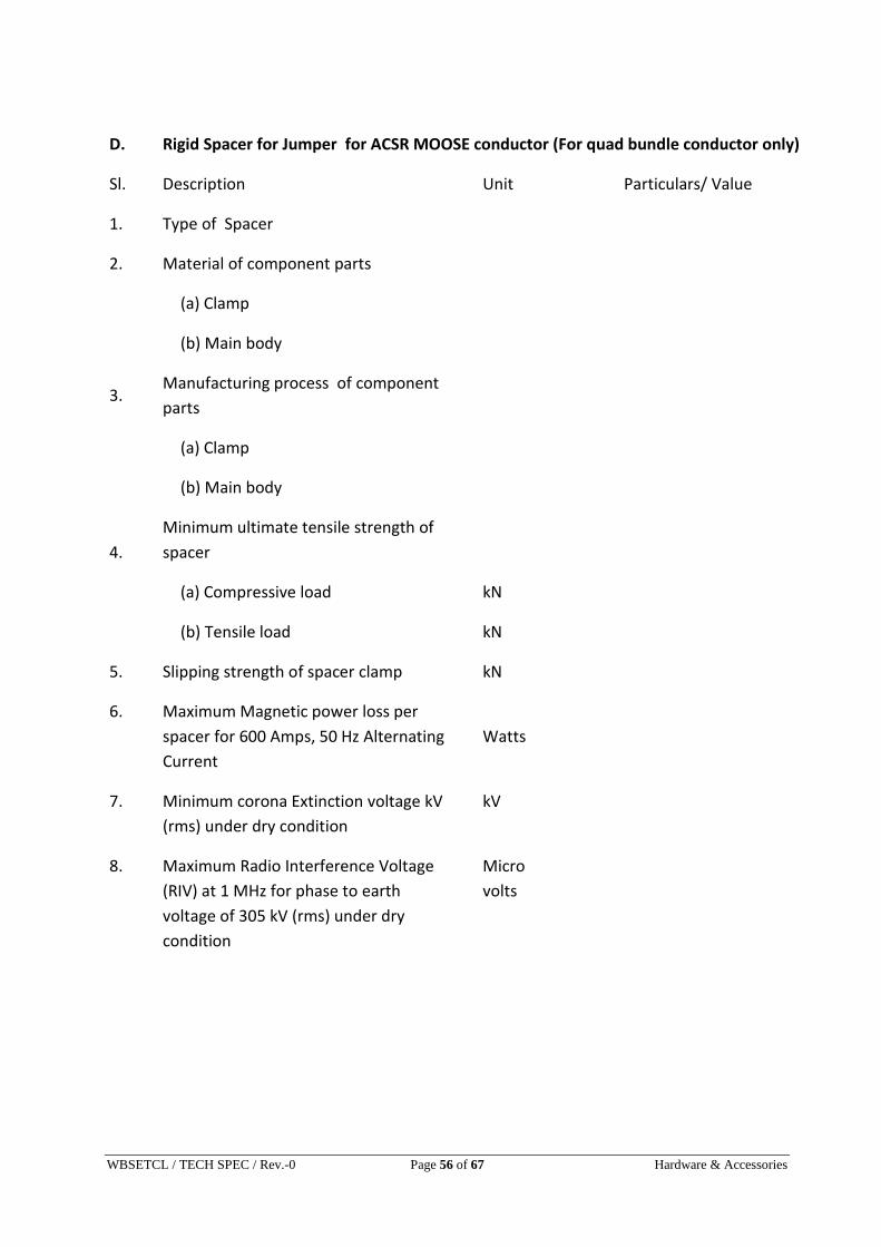
WBSETCL / TECH SPEC / Rev.-0 Page 56 of 67 Hardware & Accessories
D. Rigid Spacer for Jumper for ACSR MOOSE conductor (For quad bundle conductor only)
Sl. Description Unit Particulars/ Value
1. Type of Spacer
2. Material of component parts
(a) Clamp
(b) Main body
3. Manufacturing process of component
parts
(a) Clamp
(b) Main body
4.
Minimum ultimate tensile strength of
spacer
(a) Compressive load kN
(b) Tensile load kN
5. Slipping strength of spacer clamp kN
6. Maximum Magnetic power loss per
spacer for 600 Amps, 50 Hz Alternating
Current
Watts
7. Minimum corona Extinction voltage kV
(rms) under dry condition
kV
8. Maximum Radio Interference Voltage
(RIV) at 1 MHz for phase to earth
voltage of 305 kV (rms) under dry
condition
Micro
volts

WBSETCL / TECH SPEC / Rev.-0 Page 57 of 67 Hardware & Accessories
E. PREFORMED ARMOUR RODS FOR CONDUCTOR :
1. Maker’s name & Country :
2. Type :
3. Suitable for (conductor size) :
4. Total weight of a set of Armour
Rods (Kg) :
5. Number of wire per set (No.) :
6. Nominal diameter of :
7. Length of wire (mm) :
8. Percentage of tolerance of length
And diameter of wires (%) :
9. Overall diameter of the conductor
After use of the armour rods(mm) :
10. Conductivity of PA Rods :
11. Breaking strength (Kgf) :
12. Centre Marking provided :
13. Pitch of Helix :
14. Direction of lay :
15. Corona formation voltage :
16. Efficiency of damping (%) :
17. Packing details :
18. Standard to which conforming :
19. Material :

WBSETCL / TECH SPEC / Rev.-0 Page 58 of 67 Hardware & Accessories
F. VIBRATION DAMPERS FOR CONDUCTOR :
1. Maker’s name & Country : 2. Type : 3. Suitable for (Conductor size) : 4. Total weight of each damper(Kg) : 5. Diameter of balancing weight(mm) : 6. Length of balancing weight (mm) : 7. Weight of each balancing weight(Kg) : 8. Tolerance in balancing weight % : 9. Material, Quality, Length and size of Messenger cable : 10. Slipping strength of messenger cable (Kgf) i) Before fatigue test : ii) After fatigue test : 11. Diagram showing power dissipated By the damper for various vibration Frequency & amplitude : 12. Damping efficiency of damper : 13. Natural frequency of the damper a) Upper c.p.s. : b) Lower c.p.s. : 14. The number of dampers required per Span for various span length and their Spacings (No.) : 15. Position of fixing damper on the Conductor from the clamp mouth(mm)
a) At Tension Points: i) First Damper : ii)Second Damper :

WBSETCL / TECH SPEC / Rev.-0 Page 59 of 67 Hardware & Accessories
b) At Suspension Points:
(After fixing Armour Rods) i) First Damper : ii) Second Damper :
16. Corona Performance of the Damper : 17. Clamping bolt tightening torque :
18. Minimum fatigue strength of the damper in cycles :
19. Amplitue of fatigue at the highest Resonant frequency :
20. Slip strength of clamp : 21. Magnetic power loss of damper at 500 for Zebra Amps., 50 cycles AC :
22. Reports of damping characteristics And energy discipation :
23. Maxm. Dynamic strain on the Conductor with the damper at clamping Points : 24. Packing Details : 25. Standard to which conforming : 26. Interchangeability of Damper : 27. Maximum bending Amplitude : 28. Galvanising on Ferrous Parts: i) Minm zinc coating : ii)No. of dip per minute :

WBSETCL / TECH SPEC / Rev.-0 Page 60 of 67 Hardware & Accessories
G. HARDWARE:
1. Maker’s Name & Country :
2. Size and Designation of ball and socket with
Standard specification to which conforming :
3. Material:
a) Anchor Shackle :
b) Arcing Horn :
c) Ball Eye :
d) Ball Clevis :
e) Ball Link :
f) Chain Link :
g) Clevis Eye :
h) Clevis-Clevis :
i) Socket Eye :
j) Socket Clevis :
k) Yoke Plate (LS/TS) :
l) Suspension Clamp :
m) Dead End Clamp :
n) Corona Control Ring :
o) Security Clips & Split Pin :
p) Sag Adjustment Device :
q) Turn Buckle :
4. Minimum Failing Load (Kg) :
i) Single/Double Suspension :
ii) Single/Quad Tension :
5. Standard specification to which conforming :
6. Standard specification of Galvaniziation :
7. Number of Dip of the Galvanised iron material :
i) 3 Minutes :
ii) 1 Minute :
8. Corona Performance :
9. Reference to drawing attached :
10. Reference to type and other test reports Attached :

WBSETCL / TECH SPEC / Rev.-0 Page 61 of 67 Hardware & Accessories
H. CLAMPS (SUSPENSION & TENSION)
1. Maker’s name & Country :
2. Type :
3. Material :
4. Breaking Strength (Kgf) :
5. Slipping strength (Kgf) :
6. Angle of inclination of jumper terminal :
7. Electrical Conductivity:
a) Results of heating cycle test carried out :
b) Value of Electrical resistance :
8. a) Whether a graph showing the power
Losses in Watts against current in
Ampere is enclosed :
b) Magnetic Power Losses in Watts :
9. Reference to type tests and other test
Reports attached :
10. Weight :
11. Interchangeability :
12. Packing Details :
13. Corona Performance :
14. Galvanising of Ferrous Parts :
a) Minimum weight of zinc (gm/gm2) : b) No. of Dip per Minute :

WBSETCL / TECH SPEC / Rev.-0 Page 62 of 67 Hardware & Accessories
I. INSULATOR STRINGS :
S U S P E N S I O N T E N S I O N
1. Maker’s Name & Country :
2. a)Type of insulator units :
b) Size and designation of
Ball & Socket with standard to
Which it will conform :
3. Electro-mechanical strength
Of complete string(Kg) :
4. Whether hardware
Manufacturer guarantee
to conduct string test on
complete assembly with
Insulator Manufacturer in
some independent Laboratory:
5. Galvanizing of ferrous parts:
a) Minimum weight of Zinc (gm/m2) :
ii) Number of dip per minute :
J. MIDSPAN COMPRESSION JOINT FOR GSS EARTH WIRE
1. Maker’s name & Country :
2. Material :
3. Size :
4. Suitable for Groundwire :
5. Weight (Kg) :
6. Minimum Failing Load (Kgf) :
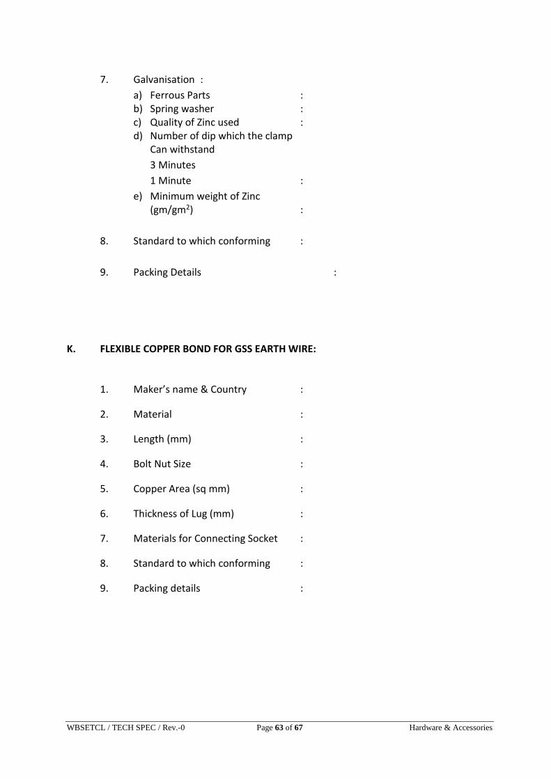
WBSETCL / TECH SPEC / Rev.-0 Page 63 of 67 Hardware & Accessories
7. Galvanisation :
a) Ferrous Parts : b) Spring washer : c) Quality of Zinc used : d) Number of dip which the clamp
Can withstand
3 Minutes
1 Minute :
e) Minimum weight of Zinc (gm/gm2) :
8. Standard to which conforming :
9. Packing Details :
K. FLEXIBLE COPPER BOND FOR GSS EARTH WIRE:
1. Maker’s name & Country :
2. Material :
3. Length (mm) :
4. Bolt Nut Size :
5. Copper Area (sq mm) :
6. Thickness of Lug (mm) :
7. Materials for Connecting Socket :
8. Standard to which conforming :
9. Packing details :

WBSETCL / TECH SPEC / Rev.-0 Page 64 of 67 Hardware & Accessories
L. SUSPENSION CLAMP FOR GSS EARTH WIRE:
1. Maker’s Name & Country :
2. Type :
3. Material :
4. Length of Clamp (mm) :
5. Suitable for Groundwire :
6. Weight (Kg) :
7. Slip Strength (Kgf) :
8. Minimum Failing Load(Kgf) :
9. Galvanisation:
a) Ferrous Parts :
b) Spring washer :
c) Quality of Zinc used :
d) Number of dip which the :
clamp can withstand
3 Minutes
1 Minute
e) Minimum weight of zinc :
(gm/gm2)
10. Standard to which conforming :
11. Packing Details :

WBSETCL / TECH SPEC / Rev.-0 Page 65 of 67 Hardware & Accessories
M. COMPRESSION TYPE DEAD END ASSEMBLY FOR GSS EARTH WIRE
1. Maker’s Name & Country :
2. Material :
3. Overall Length (mm) :
4. Jumper Length (Straight Portion)
(mm) :
5. Suitable for Groundwire :
6. Weight (Kg) :
7. Minimum Failing Load(Kgf) :
8. Outer Diameter (mm) :
i) Before Compression :
ii) After Compression :
9. Galvanisation :
a) Ferrous Parts : b) Spring washer : c) Quality of Zinc used : d) Number of dip which the :
Clamp can withstand
3 Minutes
1Minute
e) Minimum weight of zinc (gm/m2) :
10. Standard to which conforming :
1. Packing Details :
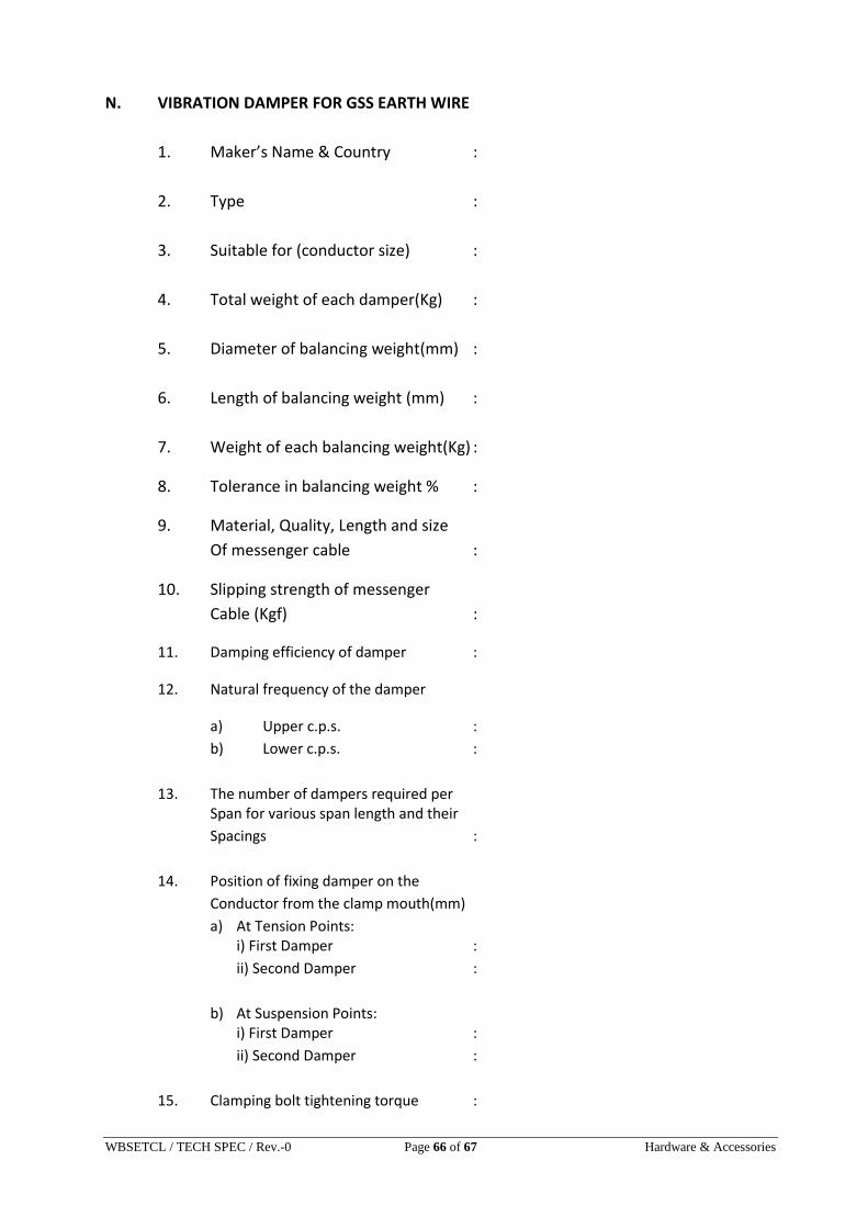
WBSETCL / TECH SPEC / Rev.-0 Page 66 of 67 Hardware & Accessories
N. VIBRATION DAMPER FOR GSS EARTH WIRE
1. Maker’s Name & Country :
2. Type :
3. Suitable for (conductor size) :
4. Total weight of each damper(Kg) :
5. Diameter of balancing weight(mm) :
6. Length of balancing weight (mm) :
7. Weight of each balancing weight(Kg) :
8. Tolerance in balancing weight % :
9. Material, Quality, Length and size
Of messenger cable :
10. Slipping strength of messenger
Cable (Kgf) :
11. Damping efficiency of damper :
12. Natural frequency of the damper
a) Upper c.p.s. :
b) Lower c.p.s. :
13. The number of dampers required per Span for various span length and their
Spacings :
14. Position of fixing damper on the
Conductor from the clamp mouth(mm)
a) At Tension Points: i) First Damper :
ii) Second Damper :
b) At Suspension Points: i) First Damper :
ii) Second Damper :
15. Clamping bolt tightening torque :

WBSETCL / TECH SPEC / Rev.-0 Page 67 of 67 Hardware & Accessories
16. Minimum fatigue strength of the
Damper in cycles :
17. Amplitude of fatigue at the highest
Resonant frequency :
18. Slip strength of clamp (Kgf) :
19. Reports of damping characteristics
And energy dissipation :
20. Maxm. Dynamic strain on the
Earthwire with the damper at clamping
Points :
21. Packing Details :
22. Standard to which conforming :
23. Interchangeability of Damper :
24. Material used for
a) Clamp : b) Messenger Cable : c) Damper :
25. Galvanising on Ferrous Part:
i)Minimum weight of zinc(gm/gm2) :
ii) No. of dip per minute :