haptic sensors & interfaces for robotic...
TRANSCRIPT

Haptic Sensors & Interfaces forRobotic Telemanipulation
Emil M. Petriu, Dr. Eng., FIEEEAna-Maria Cretu, M.A.Sc., Ph.D. candidate
School of Information Technology and EngineeringUniversity of Ottawa
Ottawa, ON., K1N 6N5 Canadahttp://www.site.uottawa.ca/~petriu
ICARA 2006

Abstract
The tutorial will discuss development issues of the human-computer and computer-robot hapticinterfaces for robotic telemanipulation:• human haptic perception;• robot haptic perception;• haptic interfaces for object manipulation in
interactive virtual environments and robotic telemanipulation systems;
• composite geometric & haptic object models whichare conformal representations of real objects, accounting for their geometric shape and elastic behaviour while interacting through direct contact with other objects;
• experimental results.

Human Haptic Perception
Human haptic perception is the result of a complex dexterous manipulation act involving two distinct components:
(i) cutaneous information fromtouch sensors which provideabout the geometric shape, contact force, elasticity, texture, and temperature of the touched object area. The highest density ofcutaneous sensors is found infingerpads (but also in thetongue, the lips, and the foot).Force information is mostlyprovided by sensors on muscles, tendons and bone joints proprioceptors;
(ii) kinesthetic information about the positions and velocities ofthe kinematic structure (bonesand muscles) of the hand
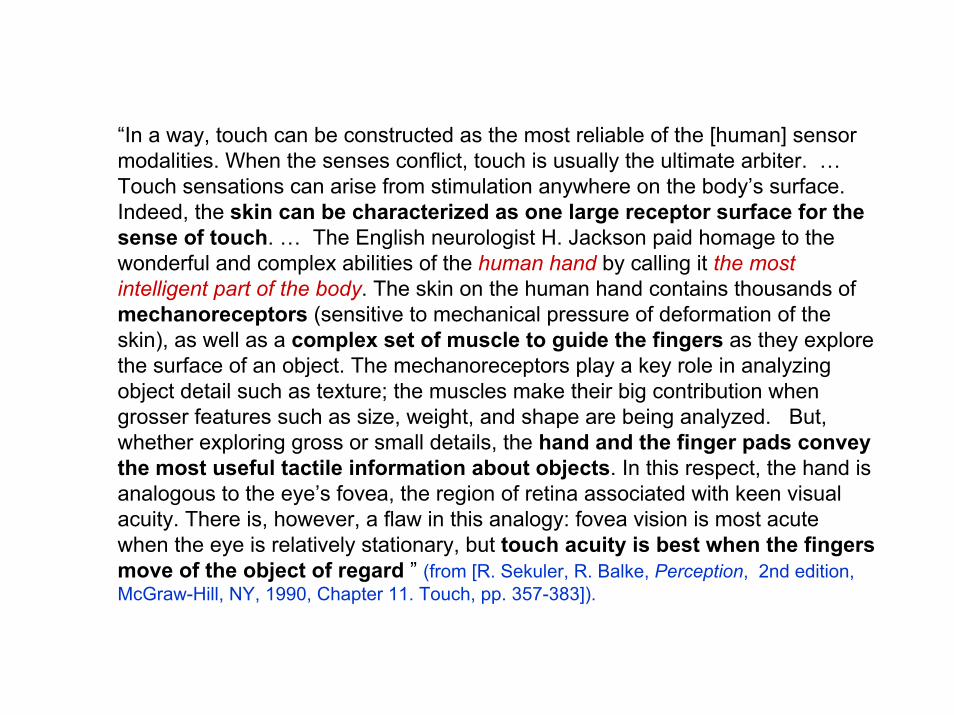
“In a way, touch can be constructed as the most reliable of the [human] sensor modalities. When the senses conflict, touch is usually the ultimate arbiter. … Touch sensations can arise from stimulation anywhere on the body’s surface. Indeed, the skin can be characterized as one large receptor surface for the sense of touch. … The English neurologist H. Jackson paid homage to the wonderful and complex abilities of the human hand by calling it the most intelligent part of the body. The skin on the human hand contains thousands of mechanoreceptors (sensitive to mechanical pressure of deformation of the skin), as well as a complex set of muscle to guide the fingers as they explore the surface of an object. The mechanoreceptors play a key role in analyzing object detail such as texture; the muscles make their big contribution when grosser features such as size, weight, and shape are being analyzed. But, whether exploring gross or small details, the hand and the finger pads convey the most useful tactile information about objects. In this respect, the hand is analogous to the eye’s fovea, the region of retina associated with keen visual acuity. There is, however, a flaw in this analogy: fovea vision is most acute when the eye is relatively stationary, but touch acuity is best when the fingers move of the object of regard ” (from [R. Sekuler, R. Balke, Perception, 2nd edition, McGraw-Hill, NY, 1990, Chapter 11. Touch, pp. 357-383]).

The sensory cortex: an oblique strip, on the side of each hemisphere, receives sensations from parts on the opposite side of the body and head: foot (A), leg (B, C, hip (D), trunk (E), shoulder (F), arm (G, H), hand (I, J, K, L, M, N), neck (O), cranium (P), eye (Q), temple (R), lips (S), cheek (T), tongue (U), and larynx (V). Highly sensitive parts of the body, such as the hand, lips, and tongue have proportionally large mapping areas, the foot, leg, hip, shoulder, arm, eye, cheek, and larynx have intermediate sized mapping areas, while the trunk, neck, cranium, and temple have smaller mapping areas.(from [H. Chandler Elliott, The Shape of Intelligence - The Evolution of the Human Brain, Drawings by A. Ravielli, Charles Scribner’s Sons, NY, 1969])

Cutaneous Sensing
Cutaneous sensors: The highest density of cutaneous sensors is found in fingertips, but also in the foot soles, the tongue, and the lips.
Force information is mostly provided by sensors on muscle tendons and bones/joints proprioceptors;
Cross section through the skin of primate finger padshowing the location of specialized nerve fiber terminals(from [R. Sekuler, R. Balke, Perception, 2nd edition, McGraw-Hill, NY, 1990]).

[Burdea& Coiffet 2003] G. Burdea and Ph. Coiffet, VirtualReality Technology, (2nd edition), Wiley, New Jersey, 2003
Cutaneous sensors => • 40 % are Meissner’s corpuscles sensing velocity and providing
information about the movement across the skin;• 25% are Merkel’s disks which measure pressure and vibrations;• 13 % are Pacinian corpuscles (buried deeper in the skin)
sensing acceleration and vibrations of about 250 Hz;• 19% are Rufini corpuscles sensing skin shear and temperature
changes.

[Burdea& Coiffet 2003]

Spatial resolution[Burdea& Coiffet 2003]
• If the sensor has a large receptive field – it has low spatial resolution (Pacinian and Ruffini)If the receptive fieldsmall - it has high spatial resolution (Meissner and Merkel)
Two-point limen test: 2.5 mm fingertip, 11 mm for palm, 67 mm for thigh (from [Burdea& Coiffet 2003] ).

Robot Haptic Sensors
Robot haptic sensing mechanisms emulatethose of the humans.

Haptic perception is the result of an active deliberate contact exploratory sensing act.
A tactile probe provides the local “cutaneous” information about the touched area of the object.
A robotic carrier providing the “kinesthetic” capability is used to move the tactile probe around on the explored object surface and to provide the contact force needed for the probe to extract the desired cutaneousinformation (e.g. local 3D geometric shape, elastic properties, and/or termic impedance) of the touched object area .
The local information provided by the tactile probe is integrated with thekinesthetic position parameters of the carrier resulting in a composite haptic model (global geometric and elastic profiles, termic impedance map) of the explored 3D object.

Biology-inspired robot haptic perception system consists of a robot “finger”, an instrumented passive-compliant wrist and a tactile probe array. Position sensors placed in the robot joints and on the instrumented passive-compliant wrist provide the kinestheticinformation. The compliant wrist allows the probe to accommodate the constraints of the touched object surface and thus to increase the local cutaneous information extracted during the active exploration process under the force provided by the robot. (from [E.M. Petriu, W.S. McMath, S.K. Yeung, N. Trif, "Active Tactile Perception of Object Surface Geometric Profiles," IEEE Trans. Instrum. Meas., Vol. 41, No. 1, pp.87-92, 1992. ]).

Tactile probe for rigid object inspection.
ELECTRICAL OUTPUT
FORCE
F1 F2
OF1
OF2
Compliant Overlay
Force Sensitive Transducer
GEOMETRIC PROFILE
ID1
ID2
It consists of a force sensitive transducer and an elastic overlay that provides a geometric profile-to-forcetransduction function .

Tactile Probe developed for the Canadian Space Agency in the early 90s.
The tabs of the elastic overlay are arranged in a 16-by-16 array having a tab on top of each node of the FSR matrix.
This tab configuration provides a de facto spatial sampling, which reduces the elastic overlay's blurring effect on the high 2D sampling resolution of the FSR transducer. (from[ S.K. Yeung, E.M. Petriu, W.S. McMath, D.C. Petriu, "High Sampling Resolution Tactile Sensor for Object Recognition," IEEE Trans. Instrum. Meas., Vol. 43, No. 2, pp.277-282, 1994] )

The tactile probe is based on a 16-by-16 matrix of Force Sensing Resistor (FSR)elements spaced 1.58 mm apart on a 6.5 cm2 (1 sq. inch) area.
The FSR elements have an exponentially decreasing electrical resistance with applied normal force: the resistance changes by two orders of magnitude over a pressure range of 1 N/cm2 to 100 N/cm2.

The elastic overlay has a protective damping effect against impulsive contact forces and its elasticity resets the transducer when the probe ceases to touch the object.
The crosstalk effect present in one piece elastic pads produces considerable blurring distortions. It is possible to reduce this by using a custom-designed elastic overlayconsisting of a relatively thin membrane with protruding round tabs. This construction allows free space for the material to expand in the x and y directions allowing for a compression in the z direction proportional with the stress component along this axis.
FORCE SENSITIVE TRANSDUCER
2D- SAMPLING ELASTIC OVERLAY
EXTERNAL FORCE
xy
z3D OBJECT

Example of GUI window (from [C. Pasca, Smart Tactile Sensor,M.A.Sc. Thesis, University of Ottawa, 2004])

Robotic Model-Based Tactile Recognition of Pseudo-Random Encoded 3D Objects
[ E.M. Petriu, S.K.S. Yeung, S.R. Das, A.M. Cretu, H.J.W. Spoelder, “Robotic Tactile Recognition of Pseudorandom Encoded Objects, IEEE Trans. Instrum. Meas., Vol.53, No.5, pp.1425-1432, 2004.] Feedback for reverse PRBS
R(n+1)= R(1) ⊕ b(2)·R(2) ⊕…⊕ b(n)·R(n)
Shift register length n
Feedback for direct PRBS R(0)= R(n) ⊕ c(n-1)·R(n-1) ⊕…⊕ c(1)·R(1)
4 R(0) = R(4) ⊕ R(1) R(5) = R(1) ⊕ R(2)
5 R(0) = R(5) ⊕ R(2) R(6) = R(1) ⊕ R(3)
6 R(0) = R(6) ⊕ R(1) R(7) = R(1) ⊕ R(2)
7 R(0) = R(7) ⊕ R(3) R(8) = R(1) ⊕ R(4)
8 R(0) = R(8) ⊕ R(4) R(9) = R(1) ⊕ R(3) ⊕ R(3) ⊕ R(2) ⊕ R(4) ⊕ R(5)
9 R(0) = R(9) ⊕ R(4) R(10) = R(1) ⊕ R(5)
10 R(0) = R(10) ⊕ R(3) R(11) = R(1) ⊕ R(4)
Table 1 Feedback equations for PRBS generation
Pseudo-Random Binary Encoding provide a practical solution allowing absolute position recovery with any desired n-bit resolution while employing only one binary track, regardless of the value of n.
R(0) = R(n) ⊕ c(n-1)·R(n-1) ⊕…⊕ c(1)·R(1)
R(n) R(n-1) R(k) R(2) R(1)
R(0)

_____________________________________________________________ n q=3 q=4 q=8 q=9
______________________________________________________________2 x2+x+2 x2+x+A x2+Ax+A x2+x+A3 x3+2x+1 x3+x2+x+A x3+x+A x3+x+A4 x4+x+2 x++x2+Ax+A2 x4+x+A3 x4+x+A5
5 x5+2x+1 x5+x+A x5+x2+x+A3 x5+x2+A6 x6+x+2 x6+x2+x+A x6+x+A x6+x2+Ax+A7 x7+x6+x4+1 x7+x2+Ax+A2 x7+x2+Ax+A3 x7+x+A8 x8+x5+2 x8+x3+x+A9 x9+x7+x5+1 x9+x2+x+A
10 x10+x9+x7+2 x10+x3+A(x2+x+1) __________________________________________________________The following relations apply: for GF(4)= GF(22): A2+A+1=0, A2=A+1, and A3=1 for GF(8)= GF(23): A3+A+1=0, A3=A+1, A4=A2+A, A5=A2+A+1,
A6=A2+1, and A7=1 for GF(9)= GF(32): A2+2A+2=0, A2=A+1, A3=2A+1, A4=2, A5=2A,
A6=2A+2, A7=A+2, and A8=1 __________________________________________________________
According to the PRMVS window property any q-valued contents observed through a n-position window sliding over the PRMVS is unique and fully identifies the current position of the window.

0 A 1 A2 A A2 A2 A2 1 1 A2 A2 A2 A A2 1 A 0 0 1 A2 A2 A 1 0 A2 A2 0 1 A A2 A2 1 0 0 A2 0 0 A A A2 1 A2 A2 1 A2 A A 0 0 A2
0 1 A 1 A 0 A2 A 0 0 A A2 0 A 1 A 1 0 A2 A2 A 0 A2 0 1 1 1 1 0 A2 0 A A2 A2
0 A2 A 1 A2 1 1 1 A A 1 1 1 A2 1 A A2
0 0 A 1 1 A2 A 0 1 1 0 A A2 1 1 A 0 0 1 0 0 A2 A2 1 A 1 1 A 1 A2 A2 0 0 1 0 A A2 A A2 0 1 A2 0 0 A2 1 0 A2 A A2 A 0 1 1 A2 0 1 0 A A A A 0 1 0 A2 1 10 1 A2 A 1 A A A A2 A2 A A A 1 A A2 1 0 0 A2 A A 1 A2 0 A A 0 A2 1 A A A2 0 0 A 0 0 1 1 A A2 A A A2 A 1 1 0 0 A 0 A2 1 A2 1 0 A 1 0 0 1 A 0 1 A2 1 A2
0 A A 1 0 A 0 A2 A2 A2 A2 0 A 0 1 A A
15-by-17 PRA obtained by folding a 255 element PRS defined over GF(4), with q=4, n=4, k1=2, k2=2, n1= qk1-1=15, and n2=(qn-1)/n1=17

The shape of the embossed symbols is specially designed for easy tactile recognition. For an efficient pattern recognition, the particular shape of the binary symbols were selected in such a way to meetthe following conditions: (i) there is enough information at the symbol level to provide an
immediate indication of the grid orientation;(ii) the symbol recognition procedure is
invariant to position, and orientation;(iii) the symbols have a certain peculiarity
so that other objects in the scene will not be mistaken for encoding symbols.
“0” “1”
“A” “A2”
The shape of the four code symbols for a PRA over GF(4) embossed on object’s surface
1” ½ ’’
1¼ “
½ ’’
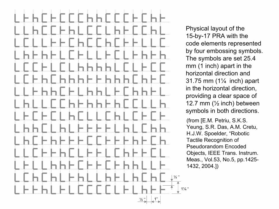
Physical layout of the 15-by-17 PRA with the code elements represented by four embossing symbols. The symbols are set 25.4 mm (1 inch) apart in the horizontal direction and 31.75 mm (1¼ inch) apart in the horizontal direction, providing a clear space of 12.7 mm (½ inch) between symbols in both directions. (from [E.M. Petriu, S.K.S. Yeung, S.R. Das, A.M. Cretu, H.J.W. Spoelder, “Robotic Tactile Recognition of Pseudorandom Encoded Objects, IEEE Trans. Instrum. Meas., Vol.53, No.5, pp.1425-1432, 2004.])

C1 C2
C3 C4
C5 C6
C7 C8
P1 P2
P3 P4
P5 P6
P7 P8
The vertex labeled models of two simple 3D objects

C4 C1
C8 C5
C1 C2
C5 C6
C2
C6
C3
C7
C3
C7
C4
C8
C1
C2
C4
C3
C8
C7
C5
C6
P3 P4
P2P1
P2P1
P6P5
P6P5
P7P8
P7P8
P3P4 P4
P8
P1
P5
P2
P6
P3
P7
Mapping the embossed PRBA on the surfaces ofthe two 3D objects
(from [E.M. Petriu, S.K.S. Yeung, S.R. Das, A.M. Cretu, H.J.W. Spoelder, “Robotic Tactile Recognition of Pseudorandom Encoded Objects, IEEE Trans. Instrum. Meas., Vol.53, No.5, pp.1425-1432, 2004.])

The PRA encoded cube.
(from [E.M. Petriu, S.K.S. Yeung, S.R. Das, A.M. Cretu, H.J.W. Spoelder, “Robotic Tactile Recognition of Pseudorandom Encoded Objects, IEEE Trans. Instrum. Meas., Vol.53, No.5, pp.1425-1432, 2004.])
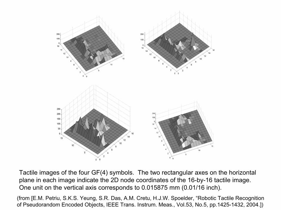
Tactile images of the four GF(4) symbols. The two rectangular axes on the horizontal plane in each image indicate the 2D node coordinates of the 16-by-16 tactile image. One unit on the vertical axis corresponds to 0.015875 mm (0.01/16 inch).
(from [E.M. Petriu, S.K.S. Yeung, S.R. Das, A.M. Cretu, H.J.W. Spoelder, “Robotic Tactile Recognition of Pseudorandom Encoded Objects, IEEE Trans. Instrum. Meas., Vol.53, No.5, pp.1425-1432, 2004.])

p1
p2
b1
b8
y1
y2
w
b2
p96
......y3
y4
Two-layer feedforwardNN architecture for the classification of the four GF(4) symbols.
Average error rate for noise ranging between 0 and 0.5
(from [E.M. Petriu, S.K.S. Yeung, S.R. Das, A.M. Cretu, H.J.W. Spoelder, “Robotic Tactile Recognition of Pseudorandom Encoded Objects, IEEE Trans. Instrum. Meas., Vol.53, No.5, pp.1425-1432, 2004.])

Composite tactile image of four symbols on an encoded object surface
(from [E.M. Petriu, S.K.S. Yeung, S.R. Das, A.M. Cretu, H.J.W. Spoelder, “Robotic Tactile Recognition of Pseudorandom Encoded Objects, IEEE Trans. Instrum. Meas., Vol.53, No.5, pp.1425-1432, 2004.])

C1
C2
C3
C4
C5
C6
C7
The four tactile recovered symbols are recognized, And their location isunequivocally identified onthe face of one of the 3D objects, using the PRA window property.
(from [E.M. Petriu, S.K.S. Yeung, S.R. Das, A.M. Cretu, H.J.W. Spoelder, “Robotic Tactile Recognition of Pseudorandom Encoded Objects, IEEE Trans. Instrum. Meas., Vol.53, No.5, pp.1425-1432, 2004.])

VideoCamera Robot
Arm
Tactile Sensors
Manipulated Object
Head Mounted Display
HapticFeedback
Virtual model of the object manipulatedin the physicalworld
VideoCamera Robot
Arm
Tactile Sensors
Manipulated Object
VideoCamera Robot
Arm
Tactile SensorsTactile Sensors
Manipulated Object
Head Mounted Display
HapticFeedback
Virtual model of the object manipulatedin the physicalworld
Head Mounted Display
HapticFeedback
Virtual model of the object manipulatedin the physicalworld
Sensor Enabled Robotic Telemanipulation
Robotic dexterous manipulationis an object-oriented act which requires not only specialized robotic hands witharticulated fingers but also tactile, force and kinesthetic sensors for the precise control of the forces and motions exerted on the manipulated object. As fully autonomous robotic dexterous manipulation is impractical in changing and unstructured environments, an alternative approach is to combine the low-level robot computer control with the higher-level perception and task planning abilities of a human operatorequipped with adequate human computer interfaces (HCI).

Telemanipulation systems should have a bilateral architecture that allows a human operator to connect in a transparent manner to a remote robotic manipulator.
Human Computer Interfaces (HCI) should provide easily perceivable and task-related sensory displays (monitors) which fit naturally the perception capabilities of the human operator.
The potential of the emergent haptic perception technologies is significant for applications requiring object telemanipulation such as: (i) robot-assisted handling of materials in industry, hazardous environments, high risk security operations, or difficult to reach environments, (ii) telelearning in hands-on virtual laboratory environments for science and arts, (iii) telemedicine and medical training simulators.

……
Tactile Sensor Interface
HapticRobot
InterfaceROBOT(k)
OBJ(i)
Robot Arm Controller
CyberGrasp ™ CyberTouch ™
Haptic Human I nterfaceUSER (k)
NETWORK NETWORK
…
{ [ 3D(j) & F(k,j) ], t }
AVATAR HAND ( k )
. . .
. . .
OBJ (N) OBJ (1)
3D Geometric & Elastic
Composite Model of Object{( x
p, y
p, z
p,E
p) | p = 1,..,P }
OBJ ( j )
Virtual Operation TheaterVirtual Operation Theater
Composite Haptic Interaction Vector between User (k) and Object (j)
ApplicationSpecific
InteractiveAction
Scenario
…
……
Tactile Sensor Interface
HapticRobot
InterfaceROBOT(k)
OBJ(i)
Robot Arm Controller
Tactile Sensor Interface
HapticRobot
InterfaceROBOT(k)
OBJ(i) OBJ(i)
Robot Arm Controller
CyberGrasp ™ CyberTouch ™
Haptic Human I nterfaceUSER (k)
CyberGrasp ™ CyberTouch ™
Haptic Human I nterfaceUSER (k)
NETWORK NETWORK
…
{ [ 3D(j) & F(k,j) ], t }
AVATAR HAND ( k )
. . .
. . .
OBJ (N) OBJ (1)
3D Geometric & Elastic
Composite Model of Object{( x
p, y
p, z
p,E
p) | p = 1,..,P }
OBJ ( j )
Virtual Operation TheaterVirtual Operation Theater
Composite Haptic Interaction Vector between User (k) and Object (j)
ApplicationSpecific
InteractiveAction
Scenario
{ [ 3D(j) & F(k,j) ], t }
AVATAR HAND ( k )
. . .
. . .
OBJ (N) OBJ (1)OBJ (1)
3D Geometric & Elastic
Composite Model of Object{( x
p, y
p, z
p,E
p) | p = 1,..,P }
OBJ ( j )
3D Geometric & Elastic
Composite Model of Object{( x
p, y
p, z
p,E
p) | p = 1,..,P }
OBJ ( j )
3D Geometric & Elastic3D Geometric & Elastic
Composite Model of Object{( x
p, y
p, z
p,E
p) | p = 1,..,P }{( x
p, y
p, z
p,E
p) | p = 1,..,P }
OBJ ( j )
Virtual Operation TheaterVirtual Operation Theater
Composite Haptic Interaction Vector between User (k) and Object (j)
ApplicationSpecific
InteractiveAction
Scenario
…
Interactive Model-Based Hapto-Visual Teleoperation - a human operator equipped with hapticHCI can telemanipulate physical objects with the help of a robotic equipped with haptic sensors.

Haptic Human Interfaces
These interfaces should allow the human operator to experience natural-like, conformal to the reality, feeling of geometric profile, force, texture, elasticitytemperature, etc.
These interfaces should have easily perceivable and sensor-transparent information displays(monitors) in such a way to offer a 1:1 mapping of the corresponding human sensory medium.

Human grasping configurations (from [Burdea& Coiffet 2003] )

Robot arm with tendon driven compliant wristSystem architecture
Video and Haptic Telerobotic System (from [E.M. Petriu, D.C. Petriu, V. Cretu, "Control System for an Interactive Programmable Robot," Proc. CNETAC Nat. Conf. Electronics, Telecommunications, Control, and Computers, pp. 227-235, Bucharest, Romania, Nov. 1982]).

Video and Haptic Telerobotic System: (a) the tactile probe , and (b) the tactile human feedback (from [E.M. Petriu, D.C. Petriu, V. Cretu, "Control System for an Interactive Programmable Robot," Proc. CNETAC Nat. Conf. Electronics, Telecommunications, Control, and Computers, pp. 227-235, Bucharest, Romania, Nov. 1982.])

Path Specifications
ENVIRONMENT
Task
ROBOT
JOINT/WHEEL SERVOS
I.R. RANGE SENSORS
Actuator
Wheel Position
WHEEL/STEER ENCODERS
VISION
ONBOARD COMPUTER
Raster Image
Local ConnectionRemote Connection
Object Identities and POSEs
Position Specifications
FRAME TRANSFORMS
TRAJECTORY PLANNER
ROBOT MODELFRAME TRANSFORMS
Robot Position
TASK PLANNER
GEOMETRIC WORLD MODEL
POSITION MODEL
OBJECT RECOGNITION
TRAJECTORY PARAMETRS ESTIMATION
Trajectory Constraints
TELEOPERATOR
VIDEO MONITOR
TAC
TILE
M
ON
ITO
R
&
JO
YSTI
CK
TACTILE SENSOR
COMPOSITE WORLD MODEL
Model-based telepresencecontrol of a robot (early 90s)

H U M A N - H A N D
TM TM
TACTILE SENSATION RECONSTRUCTION
TM = Tactile Monitor
TS TS
TACTILE IMAGE ACQUISITION
ROBOT - HAND
TS = Tactile Sensor
A tactile human feedback interface placed on the operator's palm allows the human teleoperator to virtually feel by touch the object profile measured by the tactile sensors placed in the jaws of the robot gripper (from [E.M. Petriu, W.S. McMath, "Tactile Operator Interface for Semi-autonomous Robotic Applications," Proc.Int. Symposium on Artificial Intell. Robotics Automat. in Space, i-SAIRS'92, pp.77-82, Toulouse, France, 1992.])
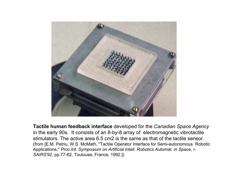
Tactile human feedback interface developed for the Canadian Space Agencyin the early 90s. It consists of an 8-by-8 array of electromagnetic vibrotactilestimulators. The active area 6.5 cm2 is the same as that of the tactile sensor.(from [E.M. Petriu, W.S. McMath, "Tactile Operator Interface for Semi-autonomous Robotic Applications," Proc.Int. Symposium on Artificial Intell. Robotics Automat. in Space, i-SAIRS'92, pp.77-82, Toulouse, France, 1992.])
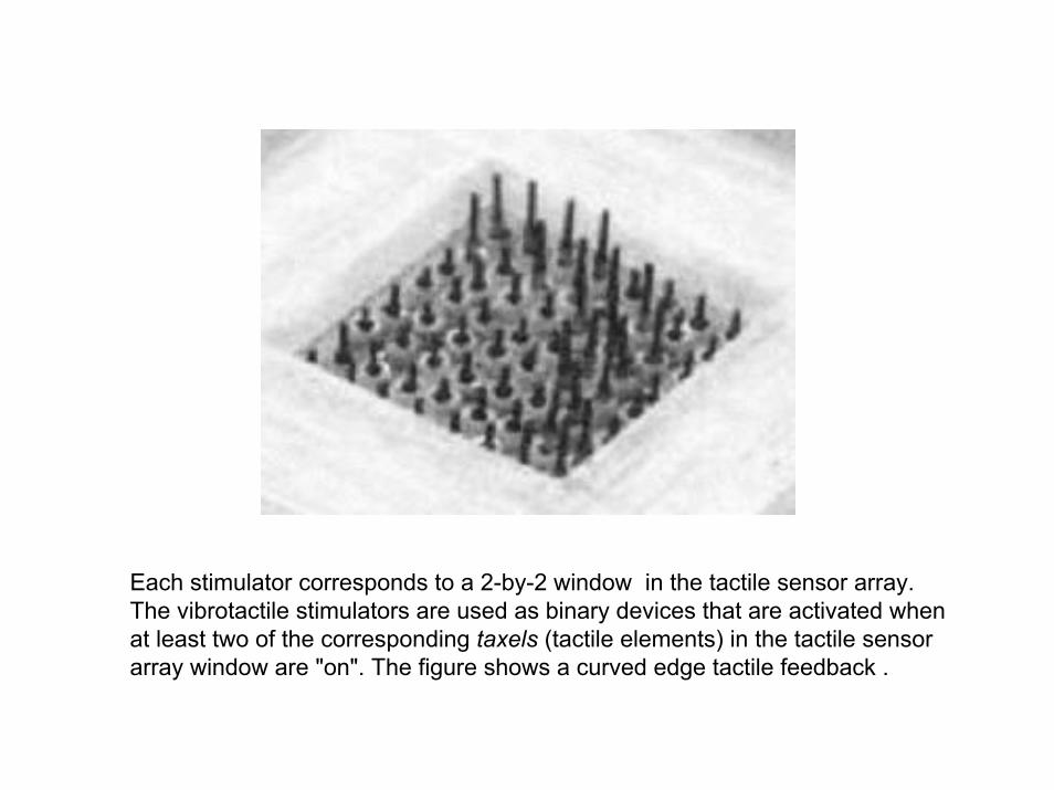
Each stimulator corresponds to a 2-by-2 window in the tactile sensor array. The vibrotactile stimulators are used as binary devices that are activated when at least two of the corresponding taxels (tactile elements) in the tactile sensor array window are "on". The figure shows a curved edge tactile feedback .

Logitech iFeel Mouse (0-125 Hz).

Immersionn_3D Interaction <http://www.immersion.com/>
CyberGlove® CyberTouch™
CyberGrasp™ CyberForce®
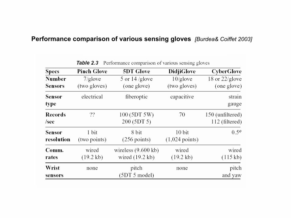
Performance comparison of various sensing gloves [Burdea& Coiffet 2003]

6 individuallycontrolled vibrotactileactuators
0-125 Hz frequency;1.2 N amplitude at 125 Hz.
CyberTouch Glove (Virtex) (from [Burdea & Coiffet 2003])

Commercial “Virtual Hand Toolkit for CyberGlove/Grasp”providing the kinesthetic human feedback interface

NN Modelling of the Geometric and Elastic Properties of 3D Objects from
Experimental Measurement Data

Model-based approach, based on the kinematics and dynamics of the object handled with the fingertips, provides a convenient representation of the dexterous manipulation.Quoting Salisbury, Conti, and Barbagli’s recent survey of haptic rendering: “improved accuracy and richness in object modeling and haptic rendering will require advances in our understanding of how to represent and render psychophysically and cognitively germane attributes of objects, as well as algorithms and perhaps specialty hardware (such as haptic or physics engines) to perform real-time computations”.
K. Salisbury, F. Conti, F. Barbagli, “Haptic Rendering: Introductory Concepts, ”IEEE Computer Graphics and Applications, Vol. 24, No. 2, pp. 24 – 32, 2004.

Modelling allows to simulate the behavior of a system for a varietyof initial conditions,excitations and systems configurations
The quality and the degree of the approximation of the model can be determined only by a validation against experimental measurements.
The convenience of the model means that it is capable of performing extensive parametric studies, in which independent parameters describing the model can be varied over a specified range in order to gain a global understanding of the response.
E.M. Petriu, "Neural Networks for Measurement and Instrumentation in Virtual Environments,” in Neural Networks for Instrumentation, Measurement and Related Industrial Applications , S. Ablameyko, L. Goras, M. Gori, V. Piuri - Eds.), NATO Science Series, Series III: Computer and System Sciences Vol. 185, pp.273-290, IOS Press, 2003

Discreet vs. Continuous Modelling of Physical Objects and Processes
x
y
CONTINUOUS MODEL• NO sampling =>
NO INTEPPOLATION COST
DISCREET MODEL•sampling => INTERPOLATION COST
y(j) = y(A) + [ x(j)-x(B)] . [ y(B)-x(A)] / [x(A)-x(B)]
x
y
x(j)
y(j) = ? A
B

Analog Computer vs. Neural Network Modelling of Continuous Physical Objects and Processes
Both the Analog Computers and the Neural Networks are continuous modelling devices.
The Analog Computer (AC) allows to solve the linear or nonlinear differential and/or integral equations representing mathematical model of a given physical process. The coefficients of these equations must be exactly known as they are used to program/adjust the coefficient-potentiometers of the AC’s computing-elements (OpAmps). The AC doesn’t follow a sequential computation, all its computing elements perform simultaneously and continuously. An interesting note, “because of the difficulties inherent in analog differentiation the [differential] equation is rearranged so that it can solved by integration rather than differentiation.” [A.S. Jackson, Analog Computation, McGraw-Hill Book Co., 1960].
The Neural Network (NN) doesn’t require a prior mathematical model. A learning algorithm is used to adjust, sequentially by trial and error during the learning phase, the synaptic-weights/coefficient-potentiometers of the neurons/computing-elements.
Similarly to the analog computer, a NN doesn’t follow a sequential computation algorithm, all its neurons performing simultaneously and continuously. The neurons are also integrative-type processing elements.

Recovery of the elastic material properties requires touching each point of
interest on the explored object surface and then conducting a strain-stress
relation measurement on each point.
Tactile probing is a time consuming Sequential operation
Find fast sampling procedures able to minimize the number of the sampling points by selecting only those points that are relevant to the elastic characteristics.
non-uniform adaptive sampling
algorithm of the object’s surface,
which exploits the SOM (self-organizing
map) ability to find optimal finite
quantization of the input space.
< = ≤≤ ⋅=
0
maxmax
max
pppp
ppppp
ififE
εεσσεεεσ
The elastic behaviour at any given
point (xp, yp, zp) on the object surface
is described by the Hooke’s law:
where Ep is the modulus of elasticity ,
s p is the stress, and e p is the strain
on the normal direction.

Adaptive Sampling Control of the Robotic Tactile Probing of Elastic Properties of 3D Object Surfaces
Initial 3D geometricmodel of the object's surface
{( xi, yi, zi) | i = 1,...,N}SOM / Neural Gas
Adaptive-sampled3D geometricmodel of the object surface{( xp, yp, zp) | p = 1,...,P}
RoboticTactileProbing
Adaptive-sampled3D geometric&
elastic composite modelof object's surface
{( xp, yp, zp, Ep) | p = 1,...,P}
xi, yi, zi
xp, yp, zp
Ep

SOM (Self Organizing Map) and Neural Gas NN architectures are both used to build compressed model of the 3D object originally defined as a point-cloud.
The weight vector will consist of the 3D coordinates of the object’s points.
During the learning procedure, the model will contract asymptotically towards the points in the input space, respecting their density and thus taking the shape of the object encoded in the point-cloud.
Data point-clouds obtained with a range scanner are used to train the network. Normalization is employed to remove redundant information from a data set, by a linear rescaling of the input vectors such that their variance is 1.
In order to evaluate the quality of the models, a straightforward measure of the precision is used. The precision is estimated as the average distance between each data vector and its winning neuron .

Qualitative comparison between the Neural Gas and the SOM adaptive sampled models.
• The map sizes are equal for both networks.
• The first column represents the original point-cloud,
• The second column represents the Neural Gas model.
• The third column represents the SOM model.

00.20.40.60.8
11.21.41.61.8
2
5 10 20 50 100 1000
number of training epochs
rela
tive
erro
r
Neural Gas SOM
For both, Neural Gas and SOM, networks the quality is improving with the number of training epochs

On the whole the quality of the Neural Gas models appears to be better. Because of the boundary problem, the SOM models are to be avoided for non-noisy data.
Neural Gas and SOM neural networks are both able to compress the initial model with the desired degree of accuracy.
The number of points can be further reduced by reducing the map size. However, there is a compromise to be made between the quality of the resulting compressed model and the map size.
Neural Gas networks are able to model an entire scene of objects while the SOM networks are not able of such a performance.

Neural Network Mapping an Clustering of Elastic Behavior from Tactile and Range Imaging for Virtualized Reality Applications
3D pointcloudof data
Samplepoints
Deformationprofiles
ForceMeasurements
FeedforwardNeural Network
F
profile(f0)profile(f1)profile(f2)profile(f3)
f0f1f2f3
Neural gasnetwork
Rangefinder
Force/Torquesensor
Starting from a 3D point-cloud, a neural gas NN yields a reduced set of points on the 3D object’s surface which are relevant for the tactile probing. The density of these tactile probing points is higher in the regions with more pronounced variations in the geometric shape. A feedforward NN is then employed to model the force/displacement behavior of selected sampled points that are probed simultaneously by a force/torque sensor and theactive range finder.

Variable elasticity object usedfor experimentation.
Sampling points selected withthe neural gas network.
(from A.M. Cretu, E.M. Petriu, P.Payeur “Neural Network Mapping and Clustering of Elastic Behavior from Tactile and Range Imaging for Virtualized Reality Applications,” submitted to IEEE Tr. Instr. Meas., Nov. 2006 ).

Elastic ball usedfor experimentation.
Sampling points selected withthe neural gas network for the ball.
(from A.M. Cretu, E.M. Petriu, P.Payeur “Neural Network Mapping and Clustering of Elastic Behavior from Tactile and Range Imaging for Virtualized Reality Applications,” submitted to IEEE Tr. Instr. Meas., Nov. 2006 ).

Different magnitudes of a normal force are applied successively on the selected sampling points using the probe attached on the force/torque sensor and a range profile is collected with the laser range finder for each force magnitude.
(from A.M. Cretu, E.M. Petriu, P.Payeur “Neural Network Mapping and Clustering of Elastic Behavior from Tactile and Range Imaging for Virtualized Reality Applications,” submitted to IEEE Tr. Instr. Meas., Nov. 2006 ).

F
Z...
H1
H45
H2
α
There is no need to recover the explicit displacement information from the range profiles. Instead the NN models use the raw range data as a function of applied force, F, without explicitly defining values for the displacement. For each cluster of similar elasticity, a feed-forward NN with two input neurons (F and α), 45 hidden neurons (H1-H45) and one output neuron (Z), is used to learn the relation between forces and the corresponding geometric profiles provided by the range finder.

The NN associated with each material were trained for 10,000 epochs using the Levenberg-Marquardt variation backpropagationalgorithm with the learning rate set to 0.1. The whole data set is used for training in order to provide enough samples. The training takes approximately 10 min. on a Pentium IV 1.3GHz machine with 512MB memory. For the rubber, the sum-squared error reached during training is 3.7 x10⁻³, for cardboard is 3.5 x10⁻² while for the foam is 2.2x10⁻². As expected, the error is lower for the rubber where data is more compact and less noisy, while it remains slightly higher for the cardboard and even higher for the foam. But in all cases, excellent convergence is achieved.
(from A.M. Cretu, E.M. Petriu, P.Payeur “Neural Network Mapping and Clustering of Elastic Behavior from Tactile and Range Imaging for Virtualized Reality Applications,” submitted to IEEE Tr. Instr. Meas., Nov. 2006).

Deformation profiles for semi-stiff material (cardboard).
(from A.M. Cretu, E.M. Petriu, P.Payeur “Neural Network Mapping and Clustering of Elastic Behavior from Tactile and Range Imaging for Virtualized Reality Applications,” submitted to IEEE Tr. Instr. Meas., Nov. 2006).

Deformation profiles for smooth material (foam).
(from A.M. Cretu, E.M. Petriu, P.Payeur “Neural Network Mapping and Clustering of Elastic Behavior from Tactile and Range Imaging for Virtualized Reality Applications,” submitted to IEEE Tr. Instr. Meas., Nov. 2006).

Real and modeled deformation curves using neural network for semi-stiff material (cardboard) under a normal force of: a) F=0.1N, b) F=0.37N, and c) F=2.65N.
(a) (b) (c)
Real and modeled deformation curves using neural network for smooth material (foam) under a normal force of: a) F=0N, b) F=0.93N, and c) F=3.37N.
(a) (b) (c)
(from A.M. Cretu, E.M. Petriu, P.Payeur “Neural Network Mapping and Clustering of Elastic Behavior from Tactile and Range Imaging for Virtualized Reality Applications,” submitted to IEEE Tr. Instr. Meas., Nov. 2006).

(a) (b)
(c)
Real and modeled deformationcurves using neural network for rubber under a normal force of: a) F=0N, b) F=65.52N, and c) F=80.5N.
(from A.M. Cretu, E.M. Petriu, P.Payeur “Neural Network Mapping and Clustering of Elastic Behavior from Tactile and Range Imaging for Virtualized Reality Applications,” submitted to IEEE Tr. Instr. Meas., Nov. 2006).

(a) (b)
Real and modeled deformation curves using neural network for rubber under forces applied at different angles: a) F=65N, α1=10° and F=65N, α2=170°,b) F=36N, α1=25°, and F=36N, α2=155
(from .A.M. Cretu, E.M. Petriu, P.Payeur “Neural Network Mapping and Clustering of Elastic Behavior from Tactile and Range Imaging for Virtualized Reality Applications,” submitted to IEEE Tr. Instr. Meas., Nov. 2006).

Real, modeled and estimated deformation profiles detail of estimated deformation profiles using neural network for rubber ball for increasing forces applied at 75-degree angle.
(from A.M. Cretu, E.M. Petriu, P.Payeur “Neural Network Mapping and Clustering of Elastic Behavior from Tactile and Range Imaging for Virtualized Reality Applications,” submitted to IEEE Tr. Instr. Meas., Nov. 2006).

Conclusions
Tele-robotic dexterous manipulation requires not only specialized robotic hands with articulated fingers but also force, tactile, and kinesthetic sensors for the precise control of the forces and motions exerted on the manipulated object.
More advanced haptic HCIs, complementing the video HCIs, need to be developed to allows human operators to have a telepresenceexperience virtually identical with what they would have had while manipulating real physical objects.
NNs consisting of a collection of simple neuron circuits provide the massive computational parallelism offering efficient storage, model transformation, and real-time rendering capabilities for large numbers of composite geometric & haptic object models involved in the model-based interactive telemanipulation.
Due to their continuous, analog-like, memory behavior, NNs are able to provide instantaneously an estimation of the output value for input values that were not part of the initial training set.

Ottawa “U” Research Group – Relevant Graduate Theses
C. Pasca, "Smart Tactile Sensor," M.A.Sc. Thesis, 2004. A.-M. Cretu, “Neural Network Modeling of 3D Objects for Virtualized Reality
Applications,” M.A.Sc. Thesis, 2003. A. Moica, "Coprocessor for Decoding Multi-Valued Pseudo-Random Sequence
Patterns," M.A.Sc. Thesis, 2000. L. Zhao, "Random Pulse Artificial Neural Network Architecture," M.A.Sc.
Thesis, 1998. S.S.K. Yeung, “Model-Based Tactile Object Recognition Using Pseudo-
Random Encoding“, Ph.D. Thesis, 1996. C. Archibald, “A Computational Model for Skills-Oriented Robot Programming,“
Ph.D. Thesis, 1995. D.M. Colven, "Tactile Pattern Recognition Using Neural Networks," M.A.Sc.
Thesis, 1993. M. Greenspan, "Robotic Active Tactile Skills," M.A.Sc. Thesis, 1992. B. Karoui, "Active Force Controlled Part Assembling for a Robotic Assembly
Cell," M.A.Sc. Thesis, 1988.

Ottawa “U” Research Group - Publications in Haptics
A.-M. Cretu, E.M. Petriu, “Neural-Network –Based Adaptive Sampling of Three Dimensional-Object Surface Elastic Properties,” IEEE Trans. Instrum. Meas.," Vol. 55, No. 2, pp. 483 - 492, 2006.
A.-M. Cretu, E.M. Petriu, G.G. Patry, “Neural-Network-Based Models of 3-D Objects for Virtualized Reality: A Comparative Study,” IEEE Trans. Instrum. Meas.," Vol. 55, No. 1, pp.99-111, 2006.
A.-M. Cretu, E.M. Petriu, P. Payeur, “Neural Network Mapping and Clustering of Elastic Behavior from Tactile and Range Imaging for Virtualized Reality Applications,” Proc. IST 2006, IEEE Intl. Workshop on Imagining Systems and Techniques, Minori, Italy, pp.17–22, April 2006.
A.-M. Cretu, J. Lang, E.M. Petriu, “A Composite Neural Gas-Elman Network that Captures Real-World Elastic Behavior of 3D Objects,” Proc. IMTC/2006, IEEE Instrum. Meas. Technol. Conf., pp. 1063-1068, Sorrento, Italy, April 2006.
P. Payeur, C. Pasca, A.-M.Cretu, E.M. Petriu, “Intelligent Haptic Sensor System for Robotic Manipulation,” IEEE Trans. Instrum. Meas., Vol. 54, No. 4, pp. 1583 – 1592, 2005.
E.M. Petriu, S.K.S. Yeung, S.R. Das, A.-M. Cretu, H.J.W. Spoelder, “Robotic Tactile Recognition of Pseudorandom Encoded Objects,” IEEE Trans. Instrum. Meas.,Vol. 53, No. 5, pp. 1425-1432, 2004.

E.M. Petriu, T.E. Whalen, V.Z. Groza, “Haptic Perception System for Robotic Tele-Manipulation,” Proc. INES 2002, 6th International Conference on Intelligent Engineering Systems 2002, pp. 51-55, Opatija, Croatia, May 2002.
S.K. Yeung, E.M. Petriu, W.S. McMath, D.C. Petriu, "High Sampling Resolution Tactile Sensor for Object Recognition," IEEE Trans. Instrum. Meas., Vol. 43, No. 2, pp.277-282, 1994.
W.S. McMath, M.D. Colven, E.M. Petriu, S.K. Yeung, "Tactile Pattern Recognition Using Neural Networks," Proc. IEEE&SICE IECON'93 Conf., pp. 1391-1394, Maui, Hawaii, 1993.
E.M. Petriu, W.S. McMath, "Tactile Operator Interface for Semi-autonomous Robotic Applications," Proc. Int. Symposium on Artificial Intell. Robotics Automat. in Space, i-SAIRS'92, pp.77-82, Toulouse, France, 1992.
E.M. Petriu, W.S. McMath, S.K. Yeung, N. Trif, "Active Tactile Perception of Object Surface Geometric Profiles," IEEE Trans. Instrum. Meas., Vol. 41, No. 1, pp.87-92, 1992.
S.K. Yeung, W.S. McMath, E.M. Petriu, N. Trif "Three Dimensional Object Recognition Using Integrated Robotic Vision and Tactile Sensing,"Proc. IEEE&RSJ Int. Workshop on Intell. Robots and Systems IROS'91, pp.1370-1373, Osaka, Japan, 1991.
E.M. Petriu, D.C. Petriu, V. Cretu, "Control System for an Interactive Programmable Robot,“ Proc. CNETAC Nat. Conf. Electronics, Telecommunications, Control, and Computers, pp.227-235, Bucharest, Romania, Nov. 1982.

References
J. Lederman, et al., "Lessons From the Study of Biological Touch for Robotic Haptic Sensing", in Advanced Tactile Sensing for Robotics (H.R. Nicholls, ed.), World Scientific, 1992.
M.H. Lee, H.R. Nicholls, “Tactile Sensing for Mechatronics - a State of the Art Survey,” Mechatronics, 9(1999), pp. 1-31, 1999.
M.J. McDonald, Active Research Topics in Human Machine Interfaces, SandiaReport, SAND2000-2779, Dec. 2000.
X. Di, et al., “ Sensor-Based Hybrid Position/Force Control of a Robot Manipulator in an Uncalibrated Environment,” IEEE Trans. Contr. Syst. Technol., Vol. 8, No. 4, 635 – 645, 2000.
A.M. Okamura, N. Smaby, M.R. Cutosky, “An Overview of Dexterous Manipulation,” Proc.ICRA’00 - IEEE Intl. Conf. Robot. Autom., pp. 255–262, Apr. 2000.
G. Robles-De-La-Torre, V.Hayward “Force Can Overcome Object Geometry In the perception of Shape Through Active Touch”, Nature, 412 (6845), pp. 445-8, 2001
A.M. Okamura, et al., “Reality-Based Models for Vibration Feedback in Virtual Environments,”IEEE/ASME Trans. Mechatronics, Vol. 6, No. 3, pp. 245-252, 2001.

• R.W. Harrigan, P.C. Bennett, Dexterous Manipulation: Making Remote Manipulators Easy to Use, Sandia Report, SAND2001-3622, Nov. 2001.• P.C. Bennett, R.J. Anderson, Robotic Mobile Manipulation Experiments at the US Army Maneuver Support Center, Sandia Report, SAND2002-1779, June. 2002• G. Burdea and Ph. Coiffet, Virtual Reality Technology (2nd edition), Wiley, NJ, 2003.• M. Benali-Khoudja, et al., “Tactile interfaces: A state-of-the Art Survey,” Proc. ISR 2004 -35th Intl.Symp. Robotics, Paris, March 2004.• K. Salisbury, F. Conti, F. Barbagli, “Haptic Rendering: Introductory Concepts,” IEEE Computer Graphics and Applications, Vol. 24, No. 2, pp. 24 – 32, 2004.• C. Sung-Ouk, A.M. Okamura, “Impedance-Reflecting Teleoperation with a Real-Time Evolving Neural Network Controller,” Proc. IROS 2004 - Intl. Conf. Intel. Rob. Syst., pp. 2241–2246, 2004.• M. Mahvash, V. Hayward, “High-Fidelity Passive Force-Reflecting Virtual Environments,” IEEE Trans. Robotics,” Vol. 21, No. 1, pp.38-46, 2005.• G. Cini et al., “A novel fingertip haptic device for display of local contact geometry,” Proc. WHC 2005 - First Joint Eurohaptics Conf. and Symp. HapticInterfaces for Virtual Environment and Teleoperator Systems, pp. 602 – 605, March 2005.
G. Robles-De-La-Torre, "The Importance of the Sense of Touch in Virtual and Real Environments“, IEEE Multimedia, 13(3), 2006, Special issue on Haptic User Interfaces for Multimedia Systems, pp. 24-30.

Thank You !