hansen technologies corporation -...
TRANSCRIPT

Bulletin R429cJune, 1998
HA4A MODULARPRESSURE REGULATORS
¾" THROUGH 6" PORT(20 MM THROUGH 150 MM)
Specifications, Applications,Service Instructions & Parts
Various ConnectionStyles and Sizesfor Refrigerants
ADDITIONAL FEATURESTolerant of Dry SystemsFor Ammonia, R22, R134a and other Hansen-
Approved RefrigerantsWide Range of OptionsInlet, Outlet, or Differential PressureWide Pressure RangesElectric Shut-Off, Dual, or Wide-Opening AvailableSafe Working Pressure: 400 psig (27 bar)CSA Certified, CRN for Canada
INTRODUCTIONThese advanced-design, strong-bodied, precision-manufactured MODULAR regulators are superior intheir ability to overcome dirt and sticky oil duringopening and tight closing. Models are available fornearly every control function requirement of industrialammonia and commercial halocarbon refrigeration.These regulators are ideal for cold storage plants,poultry plants, meat packing, fish processing,freezers, ice plants, breweries, bottling plants, heatrecovery units, petrochemical plants, pharmaceuticalplants, supermarkets, and many others.
APPLICATIONSEvaporator Pressure ControlDefrost Pressure ControlCondensing Pressure RegulationReceiver Pressure ControlHot Gas Bypass Capacity RegulationSuction Pressure ControlAir or Liquid Temperature RegulationInternal System Pressure Relief
HA4ABRegulator With Electric Wide Opening
NOW YOU HAVE A CHOICENOW YOU HAVE A CHOICENOW YOU HAVE A CHOICENOW YOU HAVE A CHOICENOW YOU HAVE A CHOICE
...A BETTER CHOICE!...A BETTER CHOICE!...A BETTER CHOICE!...A BETTER CHOICE!...A BETTER CHOICE!
HANSEN TECHNOLOGIESCORPORATION
KEY FEATURES
ISO 9002
Contents PageRegulator Variations 3Capacities 4–5Control Modules (Pilots) 6Main Regulators Only (AR1, AR3) 7Operation and Adjustment 8–11Installation Dimensions 12–13Parts List 14–18Service and Maintenance, Abbreviations 19Ordering Information, Conversions 20

2
INSTALLATIONRegulators should be protected from dirt and moistureduring storage. The arrow on the body should be inthe normal direction of refrigerant flow. These valveswill not prevent reverse flow; use check valveswhere necessary. Regulators are normally inhorizontal pipe lines with pilots and manual-openingstems on top. Do not rotate the position of the valveadapter or the valve will not operate. The systemshould be free of dirt, weld slag, and rust particles.Regulators can be equipped with separate, close-coupled inlet strainers. No small, hidden, internalscreens are used. Gauges and gauge valves shouldbe installed on the inlet and outlet to help in systemdiagnosis. Because of the many regulator pilotcombinations, during installation of a large job, theregulator nameplates should be checked againstpiping drawings to guarantee proper function foreach location. Where pilot solenoid control modulesare used, the nameplate coil voltage should bechecked before wiring. Pipe sizing, anchoring, valverating, system design, and other precautionary factorsshould be taken into consideration to ensure “liquidhammer” will not occur when the valve opens or closes.
The 5" and 6" valves are type HA4W with integralbutt weld end only. These steel-bodied regulatorsare directly welded into the pipe line. During welding,the manual-opening stem should be openeddownward several turns to protect the Teflon seatfrom weld heat.
Welds should be annealed as necessary inaccordance with good practice. Painting of valvesand welds is recommended for corrosion protection.Pipe covering, where applied, should have propermoisture barrier. Before putting valves into service,all pipe connections, valve seats, cover seals, andstem seals should be tested for leaks at pressurelevels called for in appropriate codes.
MATERIAL SPECIFICATIONSBody:
¾" through 4": Ductile iron, ASTM A536 (65,000psi tensile) (nodular iron) GGG-405" & 6": Cast steel, ASTM A352 LCB
Adapter: Ductile iron, ASTM A536 (nodular iron)GGG-40
Piston: Steel, disc type, Teflon piston sealV-Port/Seat: ductile iron, (nodular iron) GGG-40,
with Teflon seatMain Seat: ¾" through 1¼": integral ductile iron,
(nodular iron) GGG-401½" through 6": stainless steel, removable
Gaskets: Nonasbestos, graphite compositeManual Opening Stem: Steel, platedPilots: Stainless steel trimPilot Orifice: Stainless steelFlanges: Forged steel, ASTM A105Safe Working Pressure: 400 psig (27 bar)Operating Temperature: –60F to +240F (–50°C to
+115°C), lower temperatures possible atpressure downratings
SIZINGProper regulator valve sizing is important for smoothoperation and long, trouble-free life of the valve.Therefore, capacity of the regulator at both themaximum and minimum flow and pressure dropshould be analyzed. Pressure regulators will operatesatisfactorily to approximately 15% of the maximumcapacity of valve based on the correspondingpressure drop. In extreme cases, downsizing or twosmaller regulators in parallel are necessary. Forpressure drops exceeding 45 psi (3.1 bar), specialconstruction may be required. Contact the factory.
ELECTRICALWhen the electric shut-off, wide-opening, or dualfeature is supplied, a Hansen low-wattage, moldedelectrical coil is included. Standard coil voltagesare 115V, 208/230V, or 24V at 50/60Hz. Other voltagesavailable. The coil properly operates between 85%and 110% of the rated voltage. Coils should only beenergized while on the pilot solenoid tube. Unlessotherwise specified, the standard coil with a ½"fitting for conduit is supplied with valves.
A watertight solenoid coil with 18" (450 mm)long wire pigtail leads and a steel frame housingwith a ½" conduit fitting is standard.
Optional DIN Plug Coils are for grounded cordconnections and include the necessary DIN plugsocket with gasket.
Coils with Junction Boxes are optional. Integral,steel junction box for connection of the 18" (450mm) long wire pigtail leads.
Vibration-resistant, bright, long-life, neon pilot lightsare available. These pilot lights operate on primaryvoltage; a special coil with secondary winding isnot necessary. Optional watertight pilot lightassembly is also available; see page 20.
ADVANTAGESThese valves combine modern design and new agematerials with advanced manufacturing techniquesand intense quality control to offer a significantlysuperior and reliable product. Their ductile iron bodiesare stronger and more rugged than common castiron, or so called semi-steel (class B iron), valves.They are more dirt resistant than full skirted-piston-design valves. All regulators use energized Teflondirt-wiping piston seals which operate reliably, evenunder dry, oil-free conditions. The screw-on controlmodules (pilots) are easy to change and can beused on all valve sizes. All valves incorporate Teflonseating and stainless steel spring closing. Manual-opening stems are located on top of valves, up andaway from dirt and rust particles to avoid threadjamming. Nonasbestos gaskets are standard. Thesestandard regulator valves use the same flanges andspacing as R/S model A4A, except 1¼" (32 mm).Special Hansen 1¼" 4-bolt regulators are availablefrom stock to exactly replace R/S 1¼" A4A only.

3
REGULATOR VARIATIONS
NOTE: Many other control functions can be achievedby combining the control modules in differentarrangements. For example: a dual regulator withelectronic pilot and secondary relief pilot; i.e. HA4ADJ.
HA4AP
HA4AT
HA4AJ
HA4AO
HA4A
HA4AS
HA4AB
HA4AD
HA4AL
HA4AK
HA4AM
HA4A STANDARD REGULATORHA4A STANDARD REGULATORHA4A STANDARD REGULATORHA4A STANDARD REGULATORHA4A STANDARD REGULATORThis most common pressure regulatormodulates to control evaporatorpressure, condensing pressure,pressure in a vessel, or pressure in aportion of a system. It is frequentlycalled an evaporator pressure regulator(EPR) or back pressure regulator.Opens on rising inlet pressure. Seepage 10. Shown with M3W pilot.
HA4AS REGULATOR WITHELECTRIC SHUT-OFFThis control is commonly used fortemperature control or defrost.Regulates at the set-for pressure whenenergized. When de-energized, thevalve closes tight regardless of thepressure setting. See page 11.
HA4AB REGULATOR WITHELECTRIC WIDE OPENINGCommonly regulates for defrost ortemperature, but opens wide formaximum cooling. Regulating at theset-for pressure when de-energized;regulator opens when energized. Seepage 11.
HA4AD DUAL PRESSUREREGULATORRegulates (evaporator) pressure at asetting when energized, and at a highersetting for defrost, temperature control,or pressure relief when de-energized.See page 11.
HA4AL DIFFERENTIALPRESSURE REGULATORCommonly used as liquid pump relief,condenser-receiver pressure differencecontrol, discharge pressure boostingfor defrosting or heat recovery, andother similar applications. This controlmodulates to maintain the set-fordifference between inlet and outletpressure. See page 10.
HA4AK RESEATINGRELIEF REGULATORUsed for defrost, high-to-low side relief,or nonatmosphere relief to other partsof the system. This control opens whensystem upstream pressure is abovethe tagged and sealed set pointpressure, and repeatedly reseats afteroperation. See page 10.
HA4AO OUTLETPRESSURE REGULATORControls outlet pressure by openingas downstream pressure falls belowthe set point. Used for hot gas toprovide artificial refrigeration loading,for condenser and receiver pressurecontrol by means of gas bypass,limiting hot gas pressure supply indefrosting evaporator in conjunctionwith l iquid drain traps, or forcompressor suction pressure limitation.Can be combined with electric shut-off,temperature-operated, dual, or wide-opening features. See page 11.
HA4AP PNEUMATICALLYCOMPENSATED REGULATORCommonly used for precise air or liquidtemperature control via pneumaticcontroller. An air, vapor, or liquidpressure signal to the control modulebonnet increases inlet pressure fromthe set-for pressure value at a 1:1 ratio.See page 12.
HA4AT TEMPERATUREOPERATED REGULATORThe vapor pressure capillary tubingand bulb system modulates theregulator open as temperatureincreases to control air or l iquidtemperature. See page 12.
HA4AJ ELECTRONICALLYCONTROLLED REGULATORElectronic pilot and controller providesvery precise temperature control ofvarious cooled media under fluctuatingload conditions. See page 12.
HA4AM ELECTRIC MOTORCOMPENSATED REGULATORCommonly used for precise roomtemperature control or liquid chillercontrol. The controlling motor changesregulator pressure sett ing inaccordance with a temperaturecontroller. See page 13.

4
TROPEZIS)mm(
vC)vK(
ERUSSERPPORD
SSORCA�EVLAV
717R 22R
ERUTAREPMETGNITAROPAVE ERUTAREPMETGNITAROPAVE�F04�)C°04�(
�F02�)C°9.82�(
F0)C°8.71�(
F02+)C°7.6�(
F04+)C°4.4+(
�F04�)C°04�(
�F02�)C°9.82�(
F0)C°8.71�(
F02+)C°7.6�(
F04+)C°4.4+(
3/4 *")02(
4.6)5.5(
2 isp 7.4 4.6 4.7 5.9 21 1.2 8.2 8.2 6.3 4.4
5 isp 7.6 7.9 7.8 51 91 2.3 3.4 4.4 5.5 9.6
01 isp � 31 51 02 62 � 8.5 0.6 7.7 6.9
02 isp � � 91 72 53 � � 8.7 01 31
"1)52(
7.11)01(
2 isp 5.8 21 31 71 22 9.3 2.5 2.5 5.6 0.8
5 isp 21 81 61 72 43 8.5 9.7 0.8 01 31
01 isp � 32 82 73 74 � 11 11 41 81
02 isp � � 63 94 46 � � 41 91 42
11/4")23(
4.61)41(
2 isp 21 61 91 42 13 4.5 2.7 2.7 1.9 3.11
5 isp 71 52 22 83 84 1.8 11 11 41 81
01 isp � 23 93 25 66 � 51 51 02 52
02 isp � � 05 96 09 � � 02 62 43
11/2")04(
53)03(
2 isp 52 53 04 25 56 21 51 51 91 42
5 isp 73 35 84 18 201 71 42 42 03 83
01 isp � 96 48 111 141 � 13 33 24 35
02 isp � � 601 741 391 � � 34 65 27
"2)05(
74)04(
2 isp 43 74 45 07 78 61 12 12 62 23
5 isp 94 17 46 801 731 32 23 23 14 15
01 isp � 29 311 941 091 � 24 44 65 17
02 isp � � 341 891 952 � � 75 67 69
21/2")56(
77)66(
2 isp 65 77 98 411 341 52 43 43 34 35
5 isp 18 611 501 771 422 83 25 35 76 38
01 isp � 151 581 342 113 � 96 27 29 611
02 isp � � 432 423 424 � � 49 421 851
"3)08(
401)98(
2 isp 67 401 021 451 391 43 64 64 85 17
5 isp 901 751 141 932 303 15 07 17 09 211
01 isp � 402 052 923 024 � 39 79 521 651
02 isp � � 613 834 275 � � 721 761 312
"4)001(
661)241(
2 isp 121 661 191 642 903 55 37 37 29 411
5 isp 471 152 622 283 384 28 211 411 441 971
isp01 � 523 893 525 176 � 941 551 991 942
isp02 � � 505 996 319 � � 302 762 043
"5)521(
242)702(
isp2 671 242 872 853 054 08 701 701 531 661
isp5 452 563 923 755 407 021 361 661 012 162
isp01 � 474 185 567 879 � 812 622 092 363
isp02 � � 637 9101 1331 � � 592 093 694
"6)051(
314)453(
isp2 003 214 574 116 867 631 281 381 032 382
isp5 434 426 265 059 2021 402 872 282 853 644
isp01 � 908 199 5031 9661 � 173 683 694 026
isp02 � � 6521 9371 2722 � � 405 566 748
SUCTION VAPOR CAPACITIES (TONS)(1 Ton= 12,000 Btu/hr= 3.517 kW= 3042 kcal/hr)
*Optional 25% or 50% reduced capacity ¾" (20 mm) plugs are available for unusually low loads if requested.
† –40F (–40°C) and –20F (–28.9°C) capacities are based on a two stage system.
For liquid overfeed evaporator suction between normal 2:1 to 5:1 rate, add 20% to the evaporator load or use the nextlarger port size to accommodate liquid volume accompanying the suction gas and to reduce impact velocity.
Conditions: Capacities are based on the evaporator temperatures shown and +86F (+30°C) liquid. R717: For each 10F(5.6°C) lower liquid temperature, increase the above table capacity by 3%. R22: For each 10F (5.6°C) lower liquidtemperature, increase the above table capacity by 5%. To convert for R134a, multiply the R22 table values by 0.73(accuracy within 8%). For other refrigerant capacities and suitability, contact the factory.
‡ 2 psi= 0.14 bar 5 psi= 0.35 bar 10 psi= 0.69 bar 20 psi= 1.38 bar

5
EZIS)mm(
ROTALUGERSAGEGRAHCSID NOITCUSOTSSAP-YBSAGTOH
717R 22R 717R 22R
)C°03+(F68+gnisnednoC
)C°06+(F041+egrahcsiD
)C°03+(F68+gnisnednoC
)C°06+(F041+egrahcsiD
)C°03+(F68+gnisnednoC
)C°06+(F041+egrahcsiD
)C°4.9�(F51+gnisnednoC)C°4.9�(F51+
�egrahcsiD
)C°03+(F68+gnisnednoC
)C°06+(F041+egrahcsiD
)C°4.9�(F51+gnisnednoC)C°4.9�(F51+
�egrahcsiDdisp2 disp5 disp2 disp5
3/4 **" )02( 71 72 1.6 5.9 88 72 23 21
"1 )52( 13 94 11 71 061 94 85 22
11/4" )23( 44 96 61 42 422 86 18 13
11/2" )04( 49 741 33 25 974 641 371 66
"2 )05( 621 791 54 07 346 691 232 98
21/2" )56( 602 323 37 511 4501 123 083 641
"3 )08( 972 734 99 551 4241 434 315 791
"4 )001( 544 896 851 142
"5 )521( 946 7101 032 163
"6 )051( 8011 5371 393 616
OIL CAPACITIES (U.S. GPM)APPLICATION: SCREW COMPRESSOR OILPUMP RELIEF REGULATOR (HA4AL)
LIQUID CAPACITIES (U.S. GPM)APPLICATION: REFRIGERANT PUMP RELIEFREGULATOR (HA4AL)
Capacities assume no gas flashing. No capacity correctionrequired for temperatures between –40F (–40°C) and +40F(+4.4°C).
Capacities based on oil with less than 300 SSU viscosity.
✝ ✝ ✝ ✝ ✝ Bypass from intermediate pressure at saturation temperature to booster suction.
*These capacities are not for hot gas defrost relief. See the chart in the middle of this page.
**Optional 25% and 50% reduced capacity ¾" (20 mm) plugs are available.Discharge gas capacities are based on +15F (+10°C) evaporator temperature.
.GIRFER NOITACILPPA)mm(EZISTROP
3/4 )02(" )52("1 11/4 )23(" 11/2 )04(" )05("2 21/2 )56("
717R*dioneloSsaGtoH 51ot9 82ot51 93ot82 37ot93 601ot37 561ot601
feileRtsorfeDrotalugeR
42ot71 54ot42 06ot54 69ot06 041ot69 522ot041
22R*dioneloSsaGtoH 8ot6 51ot8 02ot51 23ot02 74ot23 57ot74
feileRtsorfeDrotalugeR
8ot6 51ot8 02ot51 23ot02 74ot23 57ot74
*Or an outlet pressure regulator with electric shut-off (HA4AOS).Evaporator tons at 10F (5.6°C) TD (temperature differential), valve capacities are conservative. These capacities can bemodified up or down depending on type of evaporator, temperature, mass, frost thickness, defrosting time, etc. Typicalfor –20F (–28.9°C) evaporator.
HOT GAS DEFROST NOMINAL VALVE SIZING CAPACITIES(DEFROSTING EVAPORATOR SIZE TONS)
GAS CAPACITIES (TONS)*(1 Ton= 12,000 Btu/hr= 3.517 kW= 3042 kcal/hr)
EZISTROP)mm(
717Risp03=P
)rab2(
22Risp03=P
)rab2(3/4" )02( 54 03
"1 )52( 28 65
11/4" )23( 411 87
11/2" )04( 652 861
"2 )05( 423 032
21/2" )56( 355 773
"3 )08( 337 505
EZISTROP)mm(
LIOisp03=P
)rab2(3/4" )02( 84
"1 )52( 78
11/4" )23( 221
11/2" )04( 062
"2 )05( 053
21/2" )56( 475
"3 )08( 577
Hot gas bypass capacities are based on above given temperatures.Liquid temperature is the same as condensing temperature.Evaporator temperature +40F (+4.4°C) or less for +86F (+30°C)condensing; –22F (–30°C) evaporator for +15F (–9.4°C) condensing.

6
CONTROL MODULES (PILOTS) FOR ANY REGULATOR
M3P
When installed, these control modules (pilots) enablethe main regulator to perform different controlfunctions (see page 3, Regulator Variations). Pilotsare normally factory installed, but can be retrofittedor interchanged in the field. The nonrising stem canbe adjusted by using a ¼" wrench. Catalog numbersare for the screw-on pi lot module.Interchangeable with Danfoss PM Series,size permitting.
M3
MS
M3O
M3LM3E25
M3B
M3S
M3T
M3J
M3KINLET PRESSUREINLET PRESSUREINLET PRESSUREINLET PRESSUREINLET PRESSUREOpens as inlet pressure rises. Range: A,0 to 150 psig (0 to 10 bar), Part 75-1097;or B, 30 to 300 psig (2 to 21 bar), Part75-1098. Also, Range V, 20" to 130 psig(–0.67 to +9 bar), Part 75-1099. Catalog M3.
Compact welded pressure pilot. RangeA, 0 to 150 psig (0 to 10 bar), Part 75-1126.Standard only on valve sizes ¾" to 1¼".Catalog M3W.
RESEATING RELIEFRESEATING RELIEFRESEATING RELIEFRESEATING RELIEFRESEATING RELIEFOpens wide when pressure exceedspressure setting and repeatedly reseatsafter operation. Defrost relief or high-to-low system relief. Set and tagged. Thestandard setting for ammonia defrost is70 psig (4.8 bar). Range A, 0 to 150 psig(0 to 10 bar), Part 75-1103; or Range B,30 to 300 psig (+2 to 21 bar), Part Number75-1104. Catalog M3K.
Compact welded pressure pilot. RangeA, 0 to 150 psig (0 to 10 bar), Part 75-1127.Standard on valve sizes ¾" to 1¼".Catalog M3KW.
OUTLET PRESSUREOUTLET PRESSUREOUTLET PRESSUREOUTLET PRESSUREOUTLET PRESSUREOpens as outlet pressure drops. For hotgas bypass to suction or for controlledsupply pressure of defrost hot gas. Alsoused for compressor suction pressurelimiting (crankcase pressure regulator).¼" NPT connections for outlet pressuregauge and sensing line (tubing notincluded). Range B, 30 to 300 psig (2 to21 bar), Part 75-1101; or Range V, 20" to130 psig (–0.67 to +9 bar), Part 75-1100.Catalog M3O, specify range.
DIFFERENTIAL PRESSUREDIFFERENTIAL PRESSUREDIFFERENTIAL PRESSUREDIFFERENTIAL PRESSUREDIFFERENTIAL PRESSUREMaintains set-for differential betweeninlet and outlet or other pressure source.For pump relief or any differentialcontrol. ¼" NPT connection for pressuresensing line (tubing not included). RangeA, 0 to 150 psi (0 to 10 bar) difference,Part 75-1081, Catalog M3L.
PNEUMATICALLYPNEUMATICALLYPNEUMATICALLYPNEUMATICALLYPNEUMATICALLYCOMPENSATEDCOMPENSATEDCOMPENSATEDCOMPENSATEDCOMPENSATEDAir or other pressure in the bonnet raisesinlet pressure on a 1:1 ratio. ¼" NPTconnection. Range A, 0 to 150 psig (0to 10 bar), Part 75-1081, Catalog M3P.
M3W
SOLENOIDSOLENOIDSOLENOIDSOLENOIDSOLENOIDNormally closed. Opens wide whenenergized. Requires coil. See page 2for coil selection. Less coil: Part70-1052, Catalog MS.
ELECTRONICALLYELECTRONICALLYELECTRONICALLYELECTRONICALLYELECTRONICALLYCONTROLLEDCONTROLLEDCONTROLLEDCONTROLLEDCONTROLLEDMounted electronic actuator changes thepressure set point in conjunction with acontroller and temperature sensor foreither air or liquid. Very precise. See page12 for the control package which includesthe necessary controller and sensor.Range: J1, 0 to 85 psig (0 to 6 bar), Part27B1140; or J2, 25 to 115 psig (1.7 to 8 bar),Part 27B1141. Catalog M3J.
TEMPERATURE OPERATEDTEMPERATURE OPERATEDTEMPERATURE OPERATEDTEMPERATURE OPERATEDTEMPERATURE OPERATEDBulb opens the control module ontemperature rise to maintain a constanttemperature. Part 27B1110 with a rangeof –40F to +30F (–40°C to 0°C) or Part27B1111 with a range of +15F to +75F(–10 to +25°C). Catalog M3T.
EXTERNAL CONNECTIONEXTERNAL CONNECTIONEXTERNAL CONNECTIONEXTERNAL CONNECTIONEXTERNAL CONNECTIONEnables a remote pressure source to beintroduced to the control via a pilot line(replaces a pilot). ¼" NPT with separate4" (100 mm) long weld nipple, Part35-1015, Catalog M3E25.
BLANKING PLUGSBLANKING PLUGSBLANKING PLUGSBLANKING PLUGSBLANKING PLUGSTo be used in a control module port whenthe port is not utilized. Stopping plugshave square head and are marked with“0” (75-1063). Straight through flow plugshave a hex head and are marked with“1” (75-1064). Catalog M3S (stopping)or M3B (straight through).

7
MAIN REGULATORS ONLY (AR1, AR3)
OPERATION OF REGULATORSThe regulator adapter (top cover) is available withone control module port or three control moduleports. One control module port is often used for asolenoid valve or a single pressure regulator. Threecontrol module ports are often used for a dualregulator and other multiple function variations.
When the modular regulator has three control moduleports, two are in series (SI and SII) and one is inparallel (P). Inlet pressure enters the internalequalization passage and goes to both the P portand the SI port. Inlet pressure enters the SII whenthe control module SI port is open. When the controlmodule in the SI and SII port or the P port is open,pressure enters the space above the piston whichforces the main valve seat to open and regulateflow.
Hansen regulators are normally furnished with controlmodules (pilots) installed and tested (see page 3).However, modular regulators less pilots and flangesare available on order from ¾" to 6" (20 mm to150 mm). Each AR1 and AR3 includes flange gaskets,nuts and bolts, and a plugged ¼" FPT outlet pressureaccess port. The access port is for connecting outletor differential control module sensing lines or gauges.
AR1 is the main regulator body with ONE controlmodule (pilot) port, control module not included.
AR3 is the main regulator body with THREE controlmodule (pilot) ports, for a maximum of three controlmodules, not included. The 5" and 6" (125 mm and150 mm) AR3 regulators have a single control moduleport with connection points for up to three totalports via mounted pilot piping.
TO ORDER: (Main Regulators only) Specify portsize and catalog number (AR1 or AR3).
¾" through 6"(20 mm through
150 mm)
¾" through 4"(20 mm through
100 mm)
5" & 6"(125 mm and 150 mm)
AR1 AR3

8
HA4AK RESEATING RELIEFREGULATOR
OPERATION(Same as HA4A) Inlet pressure is channeled throughthe internal equalization passage to the reseatingrelief control module. When inlet pressure exceedsthe relief setting, the control module opens wide toallow pressure to enter the space on top of thepiston. This causes the main valve seat to open andrelieve the inlet pressure, provided the outlet pressureis at least 2 psi (0.14 bar) lower. A 5 psid (.35 bar)closing spring is standard on ¾" through 1¼" valves.See page 6 for M3K pilot details.
When used for defrost relief from low side to anintermediate pressure, a check valve on the outlet isrequired to prevent back flow during refrigeration.
ADJUSTMENTThe control module is nonadjustable, factory-setand sealed. Available in Range A, 0 to 150 psig (0 to10 bar); or Range B, 30 to 300 psig (2 to 21 bar).
HA4A STANDARD REGULATOR
OPERATIONInlet pressure is channeled through the internalequalization passage to the inlet pressure controlmodule. The valve modulates open when inletpressure exceeds the pressure setting on the controlmodule. The gas or liquid passes through the inletpressure control module to enter the space on topof the piston, which forces the main valve seat toopen and regulate flow. As inlet pressure increases,the main valve seat opens further to maintain theselected inlet pressure. A minimum pressuredifference of 2 psi (0.14 bar) is adequate to fullyopen the main valve. When inlet pressure decreasesbelow the pressure setting on the control module,the closing spring will cause the main valve seat tothrottle closed.
ADJUSTMENTConnect a pressure gauge via a gauge valve at thegauge port on the regulator adapter. Set the controlmodule range spring at minimum force (controlmodule stem turned counterclockwise). Operate therefr igeration compressor system and achieveapproximate desired suction pressure. Turn thecontrol module stem clockwise until a slight increasein inlet pressure is detected by the gauge. The inletpressure setting can now be increased by turningthe control module stem clockwise or decreased byturning it counterclockwise. The system should beallowed to operate for a period of time before thefinal adjustment is made. The inlet pressure controlmodule is available in Range A, 0 to 150 psig (0 to10 bar); or Range B, 30 to 300 psig (2 to 21 bar). Avacuum Range V, 20" to 130 psig (–0.67 to +9 bar) isalso available.
HA4AL DIFFERENTIAL PRESSUREREGULATOR
OPERATIONIn let pressure ischanneled through theinternal equal izat ionpassage to thedif ferent ial pressurecontrol module. Outletpressure (or other) isintroduced to the spaceon top of the differentialpressure control modulediaphragm via anexternal sensing tube. Arange spring on the topof the control modulediaphragm allows the control of the differentialbetween inlet and outlet pressure. Increased rangespring force increases the differential setting. Inletpressure, counteracted by the range spring plusoutlet pressure, enters the space on top of the pistonwhich forces the main valve seat to open and regulateflow. The external sensing tube on the 5" & 6" valvesmust be customer supplied and field installed.
ADJUSTMENTConnect a pressure gauge via a gauge valve at thegauge port on the regulator adapter for the inletpressure reading. A pressure gauge downstream isalso required. With the control module range springforce at the minimum (control module stem turnedfully counterclockwise, at this point pressuredifferential is at minimum), slowly turn the controlmodule stem clockwise until the desired pressuredifference between the two gauges is achieved. Afinal adjustment should be made after system hasoperated for a period of time. The system must becapable of generating the desired pressure differencefor the regulator to open. Range A, 0 to 150 psig (0to 10 bar).

9
HA4AO OUTLET PRESSUREREGULATOR
OPERATIONOutlet pressure ischanneled through anexternal sensing tube tothe outlet pressure controlmodule. The out letpressure is introduced tothe space under thecontrol modulediaphragm. When outletpressure decreases belowthe outlet pressure settingthe range spring forcesthe control module toopen further. As the control module opens, moreinlet pressure enters the space on top of the pistonforcing the main valve seat to open further andregulate flow. As outlet pressure rises the controlmodule reduces the inlet pressure to the piston andthe main valve seat starts closing. The externalsensing tube on the 5" & 6" valves must be customersupplied and field installed. A 5 psid (.35 bar) closingspring is standard on ¾" through 1¼" valves. Alighter spring is available for applications where alow pressure drop is required, such as holdback orcrankcase pressure regulators.
ADJUSTMENTConnect a pressure gauge via a gauge valve to theoutlet gauge port located on the outlet pressurecontrol module or the pipe after the regulator. Withthe control module range spring at minimum force(control module stem turned counterclockwise)operate the refrigeration compressor. Turn the controlmodule stem clockwise until the desired outletpressure is achieved. Ranges available: B, 30 to300 psig (2 to 21 bar); or vacuum range V, 20" to 130psig (–0.67 to +9 bar).
HA4AS REGULATOR WITH ELECTRICSHUT-OFF
OPERATIONWhen the solenoidcontrol module isenergized, thiscontrol operates inthe same manner asthe HA4A StandardRegulator or otherpilot functions. Whende-energized, valvecloses tight to stopflow in direction ofarrow regardless ofpressure setting onthe control module.
ADJUSTMENTEnergize the solenoid control module and followthe control module adjustment procedures for theHA4A Standard Regulator. See page 10.
HA4AB REGULATOR WITH ELECTRICWIDE OPENING
OPERATIONWhen the solenoidcontrol module isde-energized, thiscontrol operates inthe same manner asthe HA4A StandardRegulator or otherpi lot funct ions.When energized,inlet pressurebypasses theconstant pressurecontrol module and enters the space on top of thepiston which forces the main valve seat to openwide to permit flow in the direction of arrow.
ADJUSTMENTWith solenoid control module de-energized, followadjustment procedures for the HA4A StandardRegulator. See page 10.
HA4AD DUAL PRESSUREREGULATOR
OPERATIONWhen the solenoidcontrol module isenergized, this valveoperates in the samemanner as the HA4AStandard Regulatoror other pi lotfunctions. When thesolenoid controlmodule is de-energized, the inletpressure is chan-neled to the higher-setting inlet pressure controlmodule and operates in the same manner as theHA4A regulator. When inlet pressure rises abovethe higher setting, the control module opens to allowinlet pressure to enter the space on top of the pistonwhich forces the main valve seat to open and regulateflow. Typically used as a combined evaporatorpressure regulator and defrost internal relief valve.
ADJUSTMENTConnect a pressure gauge via a gauge valve at thegauge port on the regulator adapter. With the solenoidcontrol module de-energized, adjust the constantpressure control module in the P port for the high-pressure setting. This may require a warm room orhot gas supply to the evaporator. Then, energize thesolenoid control module located on the series SI portand adjust the constant pressure module in the se riesSII port for the low-pressure setting. For control moduleadjustment, follow the adjustment procedures for theHA4A Standard Regulator. See page 10.
10
HA4AP PNEUMATICALLYCOMPENSATED REGULATOR
OPERATIONA pneumatic controller regulates the amount of airpressure applied to the top of the M3P control modulediaphragm. A rise in temperature sensed by thepneumatic controller reduces the air pressure tothe control module, allowing inlet pressure to enterthe space on top of the piston which forces themain valve seat to open and regulate flow. A decreasein sensed temperature increases the pressure of airto the M3P control module. This increase in airpressure reduces the opening at the M3P controlmodule and restricts the flow of inlet pressure tothe piston, thus reducing the opening at the valvemain seat. See page 6 for M3P pilot details.
ADJUSTMENTDisconnect the air line to the M3P control moduleand follow the adjustment procedures for the HA4AStandard Regulator. See page 10. This sets the lowinlet pressure setting for the regulator. Connect theair line back to the M3P control module. For every1 psi (0.069 bar) of increase in air pressure, theinlet refrigerant pressure setting increases 1 psi(0.069 bar). Adjust the controller as specified by themanufacturer. In lieu of air, low-pressure refrigerantor other fluid can be used for compensation. Thedifferential between inlet pressure and pressure tothe M3P control module must not exceed 45 psi (3.1bar). Range A, 0 to 150 psig (0 to 10 bar).
HA4AT TEMPERATUREOPERATED REGULATOR
OPERATIONTemperature changes are detected by the thermalbulb. The expansion or contraction of the chargeinside the bulb and capillary tube is transferredacross the diaphragm in the M3T control module. Arise in temperature above the set-for temperatureopens the M3T control module and allows inletpressure to enter the space on top of the pistonwhich forces the main valve seat to open and regulateflow. A decrease in temperature closes the M3Tcontrol module which allows the piston to rise andclose the main valve seat. A reverse acting model isalso available: rising temperature closes the regulator,as for reheat. See page 6 for M3T pilot details.
ADJUSTMENTConnect a pressure gauge via a gauge valve at thegauge port on the regulator adapter. Place athermometer in the cooled medium. With the systemoperating, set the M3T regulator control module tothe desired temperature by turning the adjustmentring clockwise to lower opening temperature orcounterclockwise to increase opening temperature.One turn is equivalent to a change of approximately11F (6.1°C). Tighten the locking ring after the finaladjustment has been made. Range –40F to +30F(–40°C to 0°C); or +15F to +75F (–10°C to +25°C).
HA4AJ ELECTRONICALLYCONTROLLED REGULATOR
OPERATIONThe controller receives signals from an air or liquidsensor and transmits an electrical voltage to theM3J electronic actuator control module. An increasein temperature lowers the voltage to actuator, openingthe regulator to increase flow. A decrease in sensortemperature increases the voltage from the controllerto the M3J electronic actuator control module closingthe valve to reduce flow. This precision control canmaintain temperatures within 1F (0.5°C) of setting.The M3J electronic actuator control module mustbe operated by one of the control packages below.See page 6 for M3J pilot details.
CONTROL PACKAGESECP This standard electronic control package
consists of a controller, controller base,sensor, and transformer.
DDS This control package includes the standardECP components plus a digital temperaturereadout, set-for/actual temperature switchto easily check temperature, assembled andmounted on a metal back plate. To displaythe set-for temperature, simply depress andhold the set-for/actual temperature switch.When released, the digital readout will againdisplay the actual temperature at the sensor.
DDL Same as the DDS with a minimum evaporatorpressure adjustment. This adjustment setsan evaporator pressure “floor” independentof temperature. This is ideal to prevent toocold of an evaporator surface in floodedevaporators or during loading of critical,temperature-sensitive products.
WTE2 Watertight controller enclosure for the above“DD” series control packages. This industrial-grade enclosure is polycarbonate with cleargasketed cover.
EKA46 This computer interface is available for directconnection of the electronic actuator controlmodule to a plant computer, PLC, or othercontrolling device. Input to interface is aregulated 4–20 mA or 0 to 10 volt signalfrom an intelligent control device. The EKA46package includes interface module andtransformer.
ADJUSTMENTSet the desired temperature (REF) using both coarseand fine adjustments. Set the alarm limits (LIM) ondeviation from the desired temperature, +1°C to +5°C.Adjust the alarm delay timer (DEL) to delay alarmrelease from 10 to 60 minutes. Both Proportionalamplification (Kp) and Integration time (Tn) are factoryset to 4. Consult the instruction manual or contactthe factory if adjustment is necessary. See theinstruct ions suppl ied with the EKA46 for i tsadjustment recommendations. M3J electronic actuatorcontrol module ranges: J1, 0 to 85 psig (0 to 6 bar);or J2, 25 to 115 psig (1.7 to 8 bar).

11
HA4AM ELECTRIC MOTORCOMPENSATED REGULATOR
OPERATIONThe regulator pressure setting is altered as the motorreceives a signal from a suitable temperaturecontroller. The motor responds to maintain thebalance in the electrical circuit. The rotation of themotor is transmitted through a cam, valve stem,and range spring to the top of the control modulediaphragm. An increase in temperature decreasesthe range spring force on top of the control modulediaphragm. This decrease in force on the diaphragmallows inlet pressure to pass through the controlmodule to enter the space on top of the piston whichforces the main valve seat open to reduce theevaporator pressure. A decrease in temperaturecauses an increase in the range spring force. Thisrestricts the flow of inlet pressure to the pistoncausing a reduction in the opening of the main valveseat, reducing regulator flow by raising the pressuresetting.
APPLICATIONSThis motor compensated regulator is popular forfruit storage, precision air temperature control, andliquid chiller control.
ADJUSTMENTAdjust the temperature controller as specified bythe manufacturer. Fully open the regulator manuallyby turning in (clockwise) the manual-opening stemto cool the product or room. Once the temperatureat the sensing device is approximately as desired,adjust the controller output so that the cam is rotatedto the center position. Put regulator back in automaticoperation by turning the manual-opening stem out(counterclockwise). Loosen the adjustment lockingnut. See the diagram to the right. Turn the adjustmentstem clockwise to raise the inlet pressure setting orcounterclockwise to lower the inlet pressure setting.When the desired refrigerant pressure setting isachieved, tighten the adjustment locking nut. A finaladjustment should be made after the system hasoperated for a period of time.
Using a potentiometer slide wire type of controller(typically 135 ohm), depending on product heat load,a deviation from desired temperature of about +2F to+5F (+1.1°C to +2.8°C) is normal to rotate the regulatorcam for maximum load satisfaction. As the load isreduced or as the temperature becomes lower, thecam rotates to create a higher evaporator pressurejust adequate to balance the load and maintain thedesired temperature, usually with ±1°F (0.5°C). Othercontrollers are available to operate the motor/camrotation.
EGNAR MACEGNAHCERUSSERP
NNEP LLEWYENOH
VroA
WOLESIR
)rab1.3(gisp54 )rab1.2(gisp03
HGIHESIR
)rab2.6(gisp09 )rab1.4(gisp06
The basic Electric Motor Compensated Regulatorconsists of a nonremovable control module with amotor bracket and cam. The control module isavailable in either Range A, 0 to 150 psig (0 to +10bar); or Range V, 20" to 130 psig (–0.67 to +9 bar).The motor bracket comes mounted on the controlmodule and is suitable for use with either PENN(standard) or HONEYWELL motors. Two cams areavailable: Low Rise (standard) and High Rise. Thetable below indicates the pressure change possiblefor each cam and motor combination.
The PENN motor (standard) has 270° of rotationtravel and the HONEYWELL motor has 160° of rotationtravel. Motors are available for either 135 ohm or4–20 mA control signal input and require 24 VACpower input. Electr ic proport ional thermostatcontrol lers (135 ohm output) , electronic PIDcontrollers (4–20 mA output) with sensor, and 24Vtransformers are available accessories.

12
EZISTROP)mm( H H H H
LL L L L M *W
WS,TPF SDO,NW3/4 1,"1," 1/4"
)23,52,02("90.3)87(
"77.6)271(
"57.3)59(
"36.4)711(
"02.8)802(
"49.8)722(
"91.6)751(
"83.2)06(
"70.4)301(
"02.7)381(
"07.3)49(
"05.4)411(
11/2 "2,")05,04(
"78.2)37(
"48.8)522(
"09.4)421(
"27.5)541(
"93.21)513(
"93.31)043(
"88.9)152(
"53.2)06(
"40.4)301(
"98.01)772(
"38.9)052(
"05.4)411(
21/2")56(
"26.3)29(
"96.9)642(
"75.5)141(
"35.6)661(
"10.31)033(
"30.41)653(
"88.9)152(
"53.2)06(
"40.4)301(
"10.11)082(
"38.9)052(
"26.5)341(
"3)08(
"60.4)301(
"00.01)452(
"30.6)351(
"88.6)571(
"83.51)193(
"04.61)714(
"52.21)113(
"53.2)06(
"40.4)301(
"83.31)043(
"02.21)013(
"05.6)561(
"4)001(
"96.4)911(
"65.01)862(
"85.6)761(
"64.7)981(
"10.71)234(
"15.02)125(
"21.41)953(
"96.2)86(
"83.4)111(
"10.51)183(
"70.41)753(
"60.8)502(
INSTALLATION DIMENSIONS
1½" THROUGH 4" REGULATORS ¾" THROUGH 1¼" REGULATORS
M = Additional length for close-coupled strainer
*Maximum width of valve.For ¾", 1", 1¼" valves add 3" (80 mm) to one side of the valve for external piping as found on HA4AO and HA4AL.An alternate 4-bolt version of the 1¼" valve is available with face-to-face dimension (L 1) same as R/S 1¼" for replacements.
1 2 4 3 1 2 3 4
The above dimensions do not include seal cap and solenoid coil removal height, or motor-access clearance.M3E25 = Less 4" (100 mm) long weld nipple. M3M = Electric motor compensated control module with motor.
GOLATAC 3M W3M SM O3M K3M WK3M L3M P3M J3M T3M 52E3M M3M
eziS)mm(
"5.6)561(
"21.5)031(
"52.3)38(
"57.7)791(
"5.6)561(
"21.5)031(
"5.6)561(
"5.6)561(
"36.4)811(
"5.4)411(
"1)52(
"9.41)873(
“P” DIMENSION FOR CONTROL MODULES (MM)
(MM)

13
INSTALLATION DIMENSIONS (MM)5" AND 6" REGULATORS
FOR SERIES AND PARALLEL ARRANGEMENT (AD)SI, solenoid; SII & P pressure pilots
FOR SERIES ARRANGEMENT (AS)SI, solenoid; SII pressure pilot
5" AND 6" PILOT PIPING (TOP VIEW)
EZISTROP A T
"5)521(
"50.5)821(
"62.0)6.6(
"6)051(
"60.6)451(
"82.0)1.7(
WELD END DIMENSIONS (MM)
(See page 8.)

14
PARTS LIST CONTROL MODULES
M3, M3K, M3L, M3P
M3O
MS
METI NOITPIRCSED YTQ ONTRAP
)O3M(tiKteksaG/mgarhpaiD 8011-57:fostsisnoCtiKevobA
1 ... mgarhpaiD 1 6170-57
2 ... )kciht(teksaGrewoL 2 6240-57
3 ... )niht(teksaGreppU 1 6360-57
4 ... gnir-OrewolloF 1 7330-57
5 ... rehsaWrebiF 1 7160-57
6 ... )todneerg(gnir-OmetSrewoL 1 0250-57
7 ... gnir-OmetSreppU 1 1250-57
8 ... gnir-OpaClaeS 1 1100-07
9 ... gnir-OegdirtraC 1 6940-57
METI NOITPIRCSED YTQ ONTRAP
)SM(tiKregnulP/ebuTdioneloS 9501-07:fostsisnoCtiKevobA
1 ... rehsaWlioC 1 9820-07
2 ... tuNlioC 1 1820-07
3 ... regnulP 1 5920-07
4 ... ebuTdioneloS 1 8920-07
5 ... teksaGebuTdioneloS 1 1030-07
6 ... swercSebuT 4 7920-07
METI NOITPIRCSED YTQ ONTRAP
tiKteksaG/mgarhpaiD)P3M,L3M,K3M,3M( 7011-57
:fostsisnoCtiKevobA
1 ... mgarhpaiD 1 6170-57
2 ... )kciht(teksaGrewoL 1 6240-57
3 ... )niht(teksaGreppU 1 6360-57
4 ... gnir-OrewolloF 1 7330-57
5 ... rehsaWrebiF 1 7160-57
6 ... )todneerg(gnir-OmetSrewoL 1 0250-57
7 ... gnir-OmetSreppU 1 1250-57
8 ... gnir-OpaClaeS 1 1100-07
* M3W and M3KW control modules are hermetically sealed,welded assemblies having no replaceable internal parts.See page 6 for replacement part numbers. Standard on¾"–1¼" (20–32 mm) valves.

15
PARTS LIST ¾" THROUGH 1¼" (20 MM THROUGH 32 MM)
METI NOITPIRCSED YTQ ONTRAP
tiKteksaG :fostsisnoc 3201-574 .... teksaGretpadA 1 9840-57
6 .... gnir-OpaCmottoB 1 3810-57
7 .... gnir-OmetS 1 0100-07
8 .... rehsaWmetS 1 6200-07
9 .... gnikcaPmetS 1 5200-07
01 .... tuNgnikcaP 1 9100-07
31 .... gnir-OpaClaeS 1 1100-0702 .... teksaGegnalF 2 2310-07
.... teksaGebuTdioneloS 1 1030-07
.... gnir-O&teksaGtroP 3 1701-57
11 metSgninepO-launaM 1 4610-57
21 paClaeS 1 1140-05
41 (gulPtroPeguaG 1/4 )TPN" 1 9810-57
a51 troP1,retpadA 1 3610-57
b51 troP3,retpadA 1 2610-57
61 pactekcos,stloBretpadA 4 0910-57
71 paCmottoB 1 5510-57
a81 ydoB 3/4 "1," 1 6510-57
b81 1ydoB 1/4 tloB-2," 1 4510-57
91 )suoiraV(egnalF 2 YROTCAF
12 (tloBegnalF 5/8 )"57.2x11-" 4 9330-07
(tuNegnalF 5/8 )11-" 4 6310-07
METI NOITPIRCSED YTQ ONTRAP
tiKnotsiP :fostsisnoc 9101-57
1 ... notsiP 1 1910-57
2 ... laeSnotsiP 1 3530-57
4 ... teksaGretpadA 1 9840-57
02 ... teksaGegnalF 2 2310-07
*"¾tiKtaeS/troP-V 0201-57
*"1tiKtaeS/troP-V 1201-57
*"¼1tiKtaeS/troP-V 2201-57
:fotsisnocstikevobA
a3 ... 3/4 taeS/troP-V" 1 4910-57
b3 ... taeS/troP-V"1 1 3910-57
c3 ... 11/4 taeS/troP-V" 1 2910-57
5 ... gnirpSgnisolC 1 7820-57
6 ... gnir-OpaCmottoB 1 3810-57
STIKTAES/TROP-VOA4AHDNAKA4AH*
NOITPIRCSED ONTRAP
tiKtaeS/troP-V 3/4" 9211-57
"1tiKtaeS/troP-V 0311-57
1tiKtaeS/troP-V 1/4" 1311-57
Above kits contain V-Port/Seat, bottom cap O-ring, and a5 psid (.35 bar) closing spring (Part 75-0622). A lighterspring is available (Part 75-0287).
16
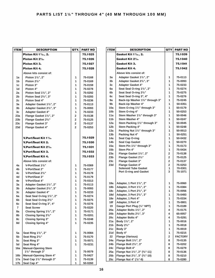
PARTS LIST 1½" THROUGH 4" (40 MM THROUGH 100 MM)
METI NOITPIRCSED .YTQ ONTRAP
"2,"½1tiKnotsiP 5201-57
"½2tiKnotsiP 6201-57
"3tiKnotsiP 7201-57
"4tiKnotsiP 8201-57
:fotsisnocstikevobA
a1 ... 1notsiP 1/2 "2," 1 8610-57b1 ... 2notsiP 1/2" 1 9610-57c1 ... "3notsiP 1 9510-57d1 ... "4notsiP 1 8720-57a2 ... 1laeSnotsiP 1/2 "2," 1 2920-57b2 ... 2laeSnotsiP 1/2 "3," 1 3920-57c2 ... "4laeSnotsiP 1 6320-57a3 ... 1teksaGretpadA 1/2 "2," 1 3110-57b3 ... 2teksaGretpadA 1/2 "3," 1 3900-57c3 ... "4teksaGretpadA 1 3320-57a32 ... 1teksaGegnalF 1/2 "2," 2 8310-57b32 ... 2teksaGegnalF 1/2" 2 5210-57c32 ... "3teksaGegnalF 2 7310-57d32 ... "4teksaGegnalF 2 3520-57
"½1tiKtaeS/troP-V 9201-57
"2tiKtaeS/troP-V 0301-57
"½2tiKtaeS/troP-V 1301-57
"3tiKtaeS/troP-V 2301-57
"4tiKtaeS/troP-V 3301-57
:fotsisnocstikevobA
a4 ... 1taeS/troP-V 1/2" 1 9630-57b4 ... "2taeS/troP-V 1 7710-57c4 ... 2taeS/troP-V 1/2" 1 8710-57d4 ... "3taeS/troP-V 1 9710-57e4 ... "4taeS/troP-V 1 3130-57a3 ... 1teksaGretpadA 1/2 "2," 1 3110-57b3 ... 2teksaGretpadA 1/2 "3," 1 3900-57c3 ... "4teksaGretpadA 1 3320-57a6 ... 1gnir-OlaeStaeS 1/2 "2," 1 4720-57b6 ... 2gnir-OlaeStaeS 1/2" 1 5720-57c6 ... "4,"3gnir-OlaeStaeS 1 6720-577 ... wercStaeS 1 0220-57a8 ... 1gnirpSgnisolC 1/2 "2," 1 1710-57b8 ... 2gnirpSgnisolC 1/2" 1 1020-57c8 ... "3gnirpSgnisolC 1 8420-57d8 ... "4gnirpSgnisolC 1 5320-57
a5 1gniRtaeS 1/2 "2," 1 4800-57b5 2gniRtaeS 1/2" 1 0710-57c5 "3gniRtaeS 1 1700-57d5 "4gniRtaeS 1 1320-57a61 metSgninepO-launaM
.. 11/2 "3hguorht" 1 9700-57b61 "4metSgninepO-launaM 1 7240-57a71 1paClaeS 1/2 "3hguorht" 1 9310-57b71 "4paClaeS 1 0620-05
METI NOITPIRCSED YTQ ONTRAP
"2,"½1tiKteksaG 9301-57
"½2tiKteksaG 0401-57
"3tiKteksaG 1401-57
"4tiKteksaG 2401-57
:fotsisnocstikevobA
a3 ... 1teksaGretpadA 1/2 "2," 1 3110-57b3 ... 2teksaGretpadA 1/2 "3," 1 3900-57c3 ... "4teksaGretpadA 1 3320-57a6 ... 1gnir-OlaeStaeS 1/2 "2," 1 4720-57b6 ... 2gnir-OlaeStaeS 1/2" 1 5720-57c6 ... "4,"3gnir-OlaeStaeS 1 6720-57a9 ... 1rehsaWpU-kcaB 1/2 "3hguorht" 1 5420-57b9 ... "4rehsaWpU-kcaB 1 1530-05a01 ... 1gnir-OmetS 1/2 "3hguorht" 1 9710-05b01 ... "4gnir-OmetS 1 3520-05a11 ... 1rehsaWmetS 1/2 "3hguorht" 1 6400-05b11 ... "4rehsaWmetS 1 7420-05a21 ... 1gnikcaPmetS 1/2 "3hguorht" 1 5400-05b21 ... "4gnikcaPmetS 1 8420-05a31 ... 1tuNgnikcaP 1/2 "3hguorht" 1 3100-05b31 ... "4tuNgnikcaP 1 1520-05a41 ... gnir-OpaClaeS 1 2340-05b41 ... teksaGpaClaeS 1 0720-05a51 ... 1niPmetS 1/2 "3hguorht" 1 3710-57b51 ... "4niPmetS 1 4340-57a32 ... 1teksaGegnalF 1/2 "2," 2 8310-57b32 ... 2teksaGegnalF 1/2" 2 5210-57c32 ... "3teksaGegnalF 2 7310-57d32 ... "4teksaGegnalF
... teksaGebuTdioneloS
... teksaGdnagnir-OtroP
213
3520-571030-071701-57
a81 1troP1,retpadA 1/2 "2," 1 0600-57b81 1troP3,retpadA 1/2 "2," 1 4830-57c81 2troP1,retpadA 1/2 "3," 1 6500-57d81 2troP3,retpadA 1/2 "3," 1 3940-57e81 "4troP1,retpadA 1 4330-57f81 "4troP3,retpadA 1 1080-57
91 (gulPtroPeguaG 1/4 )TPN" 1 9810-57a02 1stloBretpadA 1/2 "2," 4 5710-57b02 2stloBretpadA 1/2 "3," 4 7500-56c02 "4stloBretpadA 4 1920-57a12 1ydoB 1/2 "2," 1 6100-57b12 2ydoB 1/2" 1 8100-57c12 "3ydoB 1 9100-57d12 "4ydoB 1 5120-5722 )suoiraV(egnalF 2 YROTCAFa42 1tloBegnalF 1/2 "2," 8 5310-07b42 2tloBegnalF 1/2 "3," 8 2020-57c42 "4tloBegnalF 8 9720-57a52 1tuNegnalF 1/2 ("2," 5/8 )11-" 8 6310-07b52 2tuNegnalF 1/2 ("3," 3/4 )01-" 8 0120-57c52 ("4tuNegnalF 7/8 )9-" 8 0820-57

17
PARTS LIST 1½" THROUGH 4" (40 MM THROUGH 100 MM)

18
PARTS LIST 5" AND 6" (125 MM AND 150 MM)
METI NOITPIRCSED YTQ ONTRAPtiKnotsiP 0111-57
:fostsisnoctiKevobA1 ... notsiP 1 0750-572 ... laeSnotsiP 1 2060-573 ... rennI,gnir-OretpadA 1 5060-574 ... retuO,gnir-OretpadA 1 6060-57
tiKteksaG 1111-57:fostsisnoctiKevobA
3 ... rennI,gnir-OretpadA 1 5060-574 ... retuO,gnir-OretpadA 1 6060-577 ... gnir-OlaeStaeS 1 3160-5701 ... rehsaWpu-kcaB 1 4230-0511 ... gnir-OmetS 1 3920-0521 ... rehsaWmetS 1 9920-0531 ... gnikcaPmetS 1 0920-0541 ... tuNgnikcaP 1 2920-0551 ... teksaGpaClaeS 1 5130-0561 ... niPmetSgninepO-launaM 1 7060-57
... teksaGebuTdioneloS 1 1030-07
... teksaGdnagnir-OtroP 3 1701-57
METI NOITPIRCSED YTQ ONTRAP
"5tiKtaeS/troP-V 2111-57"6tiKtaeS/troP-V 3111-57
:fotsisnocstiKevobAa5 ... "5taeS/troP-V 1 0460-57b5 ... "6taeS/troP-V 1 1460-573 ... rennI,gnir-OretpadA 1 5060-574 ... retuO,gnir-OretpadA 1 6060-577 ... gnir-OlaeStaeS 1 3160-578 ... (wercStaeS 1/4 x02-" 1/2 )" 1 0220-579 ... gnirpSgnisolC 1 1060-57
6 gniRtaeS 1 8550-5771 metSgninepO-launaM 1 1850-5781 paClaeS 1 4030-05a91 troP1,retpadA 1 4550-57b91 deggulPhtiw)troP1(retpadA
stoliPelpituMrofseloHsseccA 1 0270-5702 gulPtroPeguaG 1 9810-5712 stloBretpadA 8 4060-57a22 "5,ydoB 1 2450-57b22 "6,ydoB 1 1450-57

19
SERVICE AND MAINTENANCEFailure to open: Wrong coil or control modulepilot; low line voltage; controlling switch or thermostatnot contacting; coil is burned-out; adjacent shut-offvalve closed; adapter gasket hole not aligned withhole in body and adapter; dirt packed under Teflonseal ring enabling excessive blow by; large quantityof dirt particles in solenoid module passages; dirtblocking internal pilot passages; main valve seat isdirt jammed.
Failure to close: Controlling switch or thermostatnot opening contacts; manual-opening stem is turnedin; valve installed in wrong direction; damage ordirt at main valve seat or pilot seat; piston bleedhole plugged. Under extreme conditions of liquid oroil “slugging” or pressure drops exceeding 45 psi(3.1 bar), special construction may be required.Contact the factory.
Before opening the regulator or disassemblingthe pilot for service, be sure it is isolatedfrom the system and all refrigerant is removed(pumped out to zero pressure). Follow usualrefrigeration system safe servicing procedures. Readthe CAUTION section of this bulletin on page 20.
To check solenoid pilot section of valve, disconnectthe electrical coil. Unscrew the coil nut and removewasher. Lift coil housing away from valve. Removethe four solenoid tube screws and remove solenoidtube from valve. Inspect for dirt and damage to Teflonseat and stainless steel pilot orifice. Clean, polishor replace parts as necessary, then reassemble.
¾" through 1¼" (20 mm through 32 mm): Usea 3/8" male hexagon wrench to loosen the four adapterbolts, proceeding slowly to avoid refrigerant whichmay still remain in the valve. If piston parts arestuck, remove the 2" hex bottom cap in order toseparate the valve V-port/seat from the disc piston.Inspect disc and piston bore for burrs, nicks, andother damage. Remove burrs and nicks, clean orreplace disc piston and Teflon seal ring as necessary.Long-life seal on disc piston need only be replacedwhen damaged or severely worn. If replacing thedisc piston seal, make sure the seal is properlyinstalled, with the edge up, and does not “twist”during installation. Inspect V-port/seat and main valveseat for nicks, marks, etc. The main valve seat maybe lapped by hand or power drill to remove marks.Clean, polish or replace parts as necessary. Ifnecessary, the V-port tapered seat may bereconditioned by removing up to 0.04" (1 mm) ofTeflon from it on a lathe. Lightly lubricate all partsand gaskets with soft rag containing refrigerant oil.Align hole in valve body, adapter gasket, and adapterto assure proper operation. Reassemble valve. Carefullycheck valve for leaks before returning it to service.
1½" through 6" (40 mm through 150 mm):Loosen adapter bolts using a 12" adjustable wrench(15" wrench for 5" and 6" valves), being careful toavoid any refrigerant which may still remain in thevalve. If disc piston is difficult to remove, insert a¼"-20 threaded screw ( 3/8"-16 for 5"& 6" valves) intocenter of piston and lift straight-up. Inspect pistonand piston bore for burrs, nicks and other damage.
Remove burrs and nicks, clean or replace piston asnecessary. Long-life seal on disc piston need onlybe replaced when damaged or severely worn. Ifreplacing the disc piston seal, make sure the seal isproperly installed, with the edge up, and does not“twist” during installation. These valves also havea removable stainless steel main valve seat. Toremove seat ring for inspection, first remove smallhex head seat screw. Turn the seat r ingcounterclockwise by turning it out with a wrenchand a steel bar tool positioned horizontally or bycarefully tapping the seat ring notch with a punchand a hammer. Inspect the V-port/seat and mainvalve seat for nicks, marks, and divots. The mainvalve seat may be lapped by hand or power drill toremove marks. Grease and replace the seat sealO-ring. Clean and polish, or replace the parts asnecessary. If necessary, the V-port tapered seat maybe reconditioned by removing up to 0.04" (1 mm) ofTeflon from it on a lathe. Lightly lubricate all partsand gaskets with a soft rag containing refrigerantoil. Align the hole in the valve body, adapter gasket,and adapter to assure proper operation. Reassemblethe valve. Carefully check the entire valve for leaksbefore restoring it to service.
MANUAL OPENINGThe manual-opening stem is designed to open thevalve, allowing upstream and downstream pressuresto equalize when needed for servicing, but notnecessarily to create a full-flow condition. The stemis located on the top of the adapter cover. Slowlyremove the seal cap from the manual-opening stem,being cautious to avoid any refrigerant which mayhave collected under the cap. Using an appropriatewrench, turn the stem in (clockwise) to open thevalve manually; counterclockwise to return the valveto automatic operation. Do not leave the stem partiallyopen because it may be dynamically damaged.
ABBREVIATIONSBW: Butt Weld end to match American Pipe
Schedule 40CRN: Canadian Registration NumberCSA: Canadian Standards AssociationCv: Valve capacity factor GPM (U.S.) of water at 1
psi differentialFPT: Female Pipe Thread, American National StandardKv: Valve capacity factor m 3/hr of water at 1 bar
differentialmA: milliampereMPT: Male Pipe Thread, American National StandardNEMA: National Electrical Manufacturers
Association: Class 4, watertight, approximateequivalent to IP65; Class 1, general purpose,approximate equivalent to IP20
NPT: National Pipe ThreadODS: Outside Diameter Sweat, for copper tubingPLC: Programmable Logic Controllerpsig: Pounds per square inch, gaugeR/S: Refrigerating Specialties Division, Parker
Hannifin Corp.SPDT: Single Pole Double ThrowSW: Socket Weld to accommodate American and API pipeWN or Weld: Weld Neck to match American Pipe
Schedule 40

20Printed in U.S.A.© 1998 Hansen Technologies Corporation
CAUTIONHansen pressure regulators are only for refrigerationsystems. These instructions and related safetyprecautions must be read completely and understoodbefore selecting, using, or servicing these valves.Only knowledgeable, trained refrigeration techniciansshould install, operate, or service these valves. Statedtemperature and pressure limits should not beexceeded. Adapters, bottom cap, control modules,etc., should not be removed from valves unlesssystem has been evacuated to zero pressure. Seealso Safety Precautions in the current List PriceBulletin and the Safety Precautions Sheet suppliedwith the product. Escaping refrigerant can causeinjury, particularly to the eyes and lungs.
WARRANTYAll Hansen Technologies products, except electricmotors and electronic items, are warranted againstdefects in workmanship and materials for a periodof one year F.O.B. our plant. Electric motors andelectronic items are warranted against defects for90 days. No consequential damages or field labor isincluded.
REGULATOR ACCESSORIESSTRAINERSGenerous capacity, separate, close-coupled,
60 mesh (233 Micron Rating), accessible.GAUGESPressure gauges have 3½" (90 mm) diameter
faces, safe plastic lenses, ¼" NPT connection,and recalibration features. Available forammonia and halocarbon.
GAUGE VALVESHGV1 “Long Neck” Gauge Valve, Seal Cap,
¼" MPT x FPT.PILOT LIGHTS(specify voltage)Pilot Light with NEMA 1 Box
(green, red, or amber light)Watertight Pilot Light assembly with NEMA 4 box.
(green, red, or amber light)
CONVERSIONS1" (inch) = 25.4 mm 1°F = 5/9°CTemperature in °F = 1.8°C + 32Temperature in °C = 5/9 (°F – 32)1 psi = 0.06895 bar = 6.895 kPaCv (U.S. GPM) = Kv multiplied by 1.1561 U.S. Gallon = 0.8327 Imperial Gallons = 3.7854 liters1 U.S. GPM (gallons per minute) = 0.06309 dm 3/s (or L/s) = 0.227124 m 3/hr1 American Standard Commercial Ton of Refrigeration = 12000 Btu/h = 3024 kcal/h = 3.517 kW
ORDERING INFORMATION, HA4AMODULAR PRESSURE REGULATORS
5" & 6" are type HA4W with integral butt weld end only.1¼" is standard 2-bolt flange design; 4-bolt flange styleavailable upon request to field replace 1¼" R/S.✝✝✝✝✝25% and 50% Reduced Capacity Plugs are also available.
TO ORDER: Specify type, connection style and size,range, voltage for coil, and close-coupled strainer ifrequired. The strainer is a separate stainless steel60 mesh unit which usually connects directly to theregulator inlet. Optional pilot lights are available ingreen, red, and amber. Please specify color andvoltage when ordering the valve.
TYPICAL SPECIFICATIONS“Refrigerant pressure regulators shall be pilot-operated, with disc-type pistons having Teflon seals,manual-opening stems, equipped with removable pilotmodules, Teflon main seats and stainless steel pilottrim and optional, close-coupled inlet strainers, asmanufactured by Hansen Technologies Corporationor approved equal.”
OTHER PRODUCTSSmall Pressure Regulators and ReliefsGauge, Purge, and Needle ValvesShut-Off ValvesHand Expansion Valves (Regulators)Refrigerant Solenoid ValvesRefrigerant Check ValvesGas-Powered ValvesRefrigerant Float SwitchesFloat Drain RegulatorsRefrigerant Liquid PumpsAUTO-PURGER®sVari-Level ® Adjustable Level ControlsTechni-Level ® Transducer ProbesFrost Master ® Defrost ControllersPressure-Relief Valves
HANSEN TECHNOLOGIESCORPORATION6827 High Grove BoulevardBurr Ridge, Illinois 60521 U.S.A.Telephone: (630) 325-1565Toll-free: 1-800-426-7368FAX: (630) 325-1572
TROPEZIS)mm(
NOITCENNOCEGNALFSEZIS&SELYTS
NW,WS,TPF SDO
DTS OSLA DTS3/4" )02( 3/4" 1,"1 1/4" 7/8"
"1 )52( "1 3/4 1," 1/4" 11/8"11/4" )23( 11/4" 3/4 "1," 13/8"11/2" )04( 11/2" "2 15/8"
"2 )05( "2 11/2" 21/8"21/2" )56( 21/2" "3 25/8"
"3 )08( "3 � 31/8""4 )001( "4 � 41/8""5 )521( WB"5 � �"6 )051( WB"6 � �
✝✝✝✝✝