hanging and framing curved ceilings grid systems hanging and framing curved ceilings technical guide...
TRANSCRIPT

DRYWALL Grid Systems Hanging and Framing
Curved Ceilings
T E C H N I C A L G U I D E DrywallGridSystem
Between us, ideas become reality.®
CEILING&WALL SYSTEMS
3540 DomeCeilingsTG_310b 3/26/10 4:08 PM Page i

ii
DrywallGridSystem TABLE OF CONTENTS
Features and Benefits ..................................................................................................................................1Performance ....................................................................................................................................................1Code Compliance ..........................................................................................................................................1Components ..................................................................................................................................................2Faceted Main Beam........................................................................................................................................2Main Beams ....................................................................................................................................................2Cross Tees ......................................................................................................................................................2Furring Hat Channel ........................................................................................................................................3Wall Molding ....................................................................................................................................................3G-40 and G-90 Corrosion Prevention ............................................................................................................3Accessories....................................................................................................................................................4Curving Main Beams ....................................................................................................................................5Making a Template........................................................................................................................................6Establishing an Arc..........................................................................................................................................6Completing the Template ................................................................................................................................6Arches and Barrel Vaults ..............................................................................................................................7Working with Vaults ........................................................................................................................................7Barrel Vault ......................................................................................................................................................8Vault with Perimeter Light Cove......................................................................................................................8Floating Vault ..................................................................................................................................................8Barrel Vaults and Clouds..............................................................................................................................9Double Barrel Vault..........................................................................................................................................9Ceiling Cloud ..................................................................................................................................................9Domes ..........................................................................................................................................................10Working with Domes ....................................................................................................................................10Options for Top of Dome............................................................................................................................11Vertical Brace ................................................................................................................................................11Electrical Chain..............................................................................................................................................11Electrical Box ................................................................................................................................................11Light Fixture ..................................................................................................................................................11Folded Plate Dome........................................................................................................................................11Cone ..............................................................................................................................................................11Self Supporting Tee Top................................................................................................................................11Domes ..........................................................................................................................................................12Dome with Skylight ......................................................................................................................................12Typical Details................................................................................................................................................12Other Domes................................................................................................................................................13Multi-Level Dome ..........................................................................................................................................13Saucer Dome Up ..........................................................................................................................................13Saucer Dome Down......................................................................................................................................13Saucer Dome ................................................................................................................................................13Checker Board Dome ..................................................................................................................................13Egg or Elliptical Dome ..................................................................................................................................13Pole Dome ....................................................................................................................................................13Step Up Dome ..............................................................................................................................................13Offset 2-Way Radius Dome ..........................................................................................................................13Creating an Ellipse ......................................................................................................................................14Finishing and Exterior Application ............................................................................................................16Drywall Bending Radius................................................................................................................................16Control Joints ................................................................................................................................................16Expansion Joints ..........................................................................................................................................16Radius in Feet ..............................................................................................................................................17Estimating Materials ..................................................................................................................................18
3540 DomeCeilingsTG_310b 3/26/10 4:08 PM Page ii
Performance
•PeakForm® patented profile increasesstrength and stability for improved performance during installation
•SuperLock™ 2 main beam clip is engineered for a strong secure connection and fast accurate alignmentconfirmed with an audible click; easy toremove and relocate
•ScrewStop® reverse hem preventsscrew spin off on 1-1/2" wide face
•Faceted main beam — pre-notchedmain beam to simplify assembly ofcurved sections; all notched locationsalong main beam require installation of RC2 clip
HD8906F08 – Prenotched 8" O.C.HD8906F16 – Prenotched 16" O.C.
•Rotary-stitched — Greater torsionalstrength and stability
•1-1/2" wide face main beams and cross tees — Easy installation of screwapplied gypsum wallboard
•G40 Hot dipped galvanized coating —Corrosion resistance
•G90 Hot dipped galvanized coating —Superior corrosion resistance for exterior applications (HD8906F08 and HD8906F16 not available in G90 coating)
•Cross tee Spacing:24" O.C. for 5/8" drywall16" O.C. for 1/2" drywall8" O.C. for tight radius
Code Compliance
•Meets ASTM C635
•Meets ASTM C645
•Meets ASTM C840
•Meets ASTM C636
•Meets ASTM C754
•Department of State Architect — DSA PA105
•City of LA — RR 25348
•Uniform Building Code, ContinuousMembrane, One Level. Per Section25.210 single level drywall ceilings donot require lateral bracing when wallsare not over 50 feet apart. When wallsare over 50 feet apart, the ceilingshould be examined for bracing requirements
• IBC categories D, E and F single layer drywall ceilings are exempt fromlateral force bracing requirements, regardless of room size
• Consult local codes for specific requirements
1
DrywallGridSystemFEATURES AND BENEFITS
1
3540 DomeCeilingsTG_310b 3/26/10 4:08 PM Page 1

Item # Length Face Dimension
Profile Height
Fire Rated Routs
Load Test Data (Lbs./LF)PerspectiveL/360
wires atL/240
wires at
72" 72"
XL8965 72" 1-1/2" 1-1/2" No 6 routs – starting24" from each end†
4.27 6.4
50" 50"
XL8947PXL8947PG90
50" 1-1/2" 1-1/2" Yes 8 routs – starting10" from each end†
13.0 19.5
2' 3' 4' 2' 3' 4'
XL8945PXL8945PG90XL8945HRC
48" 1-1/2" 1-1/2" Yes 9 routs – centerrout and starting
10" from each end†
15.0 22.5
XL8341 48" 15/16" 1-11/16" Yes 3 routs – starting12" from each end
16.59 24.8
XL7341 48" 15/16" 1-11/16" No 3 routs – starting12" from each end
16.59 24.8
XL7936G90 36" 1-1/2" 1-1/2" No none 33.3 50
For more information call 1 877 ARMSTRONG2
DrywallGridSystem
Faceted Main Beam
8 on center 144
16 on center4 12
* Tested flat per ASTM C635 with RC2 clips at each faceted location† Type “F” fixture compatible
† Type “F” fixture compatible
COMPONENTS
Cross Tees
Main Beams
HD8906F16 – Faceted 16" O.C. Use for radius over 15' (Directional Main Beam)
HD8906F08 – Faceted 8" O.C. Use for radius 15' or less
Item # Length FaceDimension
ProfileHeight
DutyLoad
FireRated Routs
Load Test Data (Lbs./LF)PerspectiveL/360
wires atL/240
wires at
51 routs –starting
2-1/4" from each end†
HD8906F08 51 RoutsHD8906F16 42 Routs
starting2-1/4" from each end
2' 3' 4' 2' 3' 4'
HD8906HD8906G90HD8906HRC 144" 1-1/2" 1-11/16"
HeavyDuty Yes 95.5 35.8 18.76 143.0 57.3 28.14
HD8906F08*HD8906F16* 144" 1-1/2" 1-11/16" – No 12.3 18.4
3540 DomeCeilingsTG_310b 3/26/10 4:08 PM Page 2

Corrosion PreventionCorrosion prevention is an essential factor in the economical utilization of galvanized sheetmetal for ceiling grid. Armstrong provides G40 for interior construction per ASTM C645.When conditions include exposure to extreme moisture and salt water, G90 is available per ASTM A653.
NOTE: High Recycled Content (HRC) grid items are available as a special order.
DrywallGridSystem
For more information call 1 877 ARMSTRONG
COMPONENTS
† Type “F” fixture compatible
3
Cross Tees
Wall Molding
Item # Length
FaceDimension
ProfileHeight
FireRated Routs
Load Test Data (Lbs./LF)PerspectiveL/360
wires atL/240
wires at
2' 3' 4' 2' 3' 4'
XL8925XL8925G90
26" 1-1/2" 1-1/2" Yes 2 routs – 12"from each end†
98.0 117.0
XL8926XL8926G90
24" 1-1/2" 1-1/2" Yes 3 routs – center rout and 10" from each end†
129.0 158.0
XL7918 14" 1-1/2" 1-1/2" Yes none†
Item # Length Description Profile Perspective
7858 144" Reverse Angle Molding nominal 1-9/16" x 15/16"
7838 120" Unhemmed Channel Molding nominal 3/4 x 1-9/16" x 1-1/4"
KAM21025KAM21020
144" Knurled Angle Molding nominal2" x 2"
KAM12KAM12G90KAM12HRC
144" Knurled Angle Molding nominal1-1/4" x 1-1/4"
KAM10 120" Knurled Angle Molding nominal1-1/4" x 1-1/4"
LAM12LAM12G90LAM12HRC
144" Locking Angle Molding nominal1-1/4" x 1-1/4"
90°15/16"(24mm)
1-9/16"(40mm)
3/4n
1-9/16n
1-1/4n
1-1/4"
1-1/4"
1-1/4"
1-1/4"
2"
2"
3540 DomeCeilingsTG_310b 3/26/10 4:08 PM Page 3

For more information call 1 877 ARMSTRONG4
DrywallGridSystem
A variety of drywall grid accessories are available to provide problem-solving solutions that savetime, labor and money. For a complete list of accessories, request submittal CS-3082.
ACCESSORIES
Description Perspective Application
Drywall Attachment Clip facilitates transition from drywall to acoustical ceiling; locks under bulb of grid section to pre-vent upward movement and provide secure attachment sur-face on one side of exposed grid
30, 45, 60 and 90 degree Drywall Angle Clips are used tocreate positive and secure angles for drywall and ceiling in-stallations on either main beams or cross tees
Partition Top Trim used to finish the top of a drywall partition for a continuous drywall/acoustical ceiling interface
DW58LT-Transition Clip for 5/8" Drywall with Locking Tabs; facilitates transition from drywall to acoustical ceiling; one-sided hold-down clip; eliminates need for drywall bead. Locking tabs provide secure location for DGS tees.
DW50LT-Transition Clip for 1/2" Drywall with Locking Tabs; facilitates transition from drywall to acoustical ceiling; one-sided hold-down clip; eliminates the need for a drywallbead. Locking tabs provide secure location for DGS tees.
Main Beam Adapter Clip attaches to web of grid section;provides larger surface for screw attachment; used as a hold-down clip for thin material (metal or plastic lay-in panels);fastens drywall track to underside of exposed grid with lay-inpanels, leaving grid face free of screw holes
Main Beam Spacer Clip (2" in length) used to space two par-allel main beams 2" O.C. for air supply or return
Adjustable Grid Spacer Clip is used to space two parrallelmain beams for light fixtures, air diffusers, etc.; allows for 1/4"adjustments with three different clips
Cross Tee Adapter Clip - Used to attach field cut cross tees to main beams
Double Drywall Clip to hang suspension system belowexisting 1-1/2" grid face, transferring weight directly to hanger wire; may be used to preserve the fire rating of anexisting ceiling and to support heavy accessories; allows for double layer of 5/8" gypsum board
Direct Load Ceiling Clip to hang suspension system below existing 15/16" grid face, transferring weight directly to hanger wire; may be used to preserve the fire rating of an existing ceiling and to support heavy accessories
Drywall Clip allows for a “second” ceiling to be installed below a drywall ceiling; attach through installed drywall to supporting structure.
Item #
DWACS
DW30CDW45CDW60CDW90C
TT10
DW58LT
DW50LT
MBAC
MBSC2
GSC9GSC12GSC16
XTAC
DDC
DLCC
DWC
Quantity
100
250250250250
30
125
125
70
200
100100100
100
250
250
250
30˚ 45˚
60˚ 90˚
3540 DomeCeilingsTG_310b 3/26/10 4:08 PM Page 4

DrywallGridSystemCURVING MAIN BEAMS
For more information call 1 877 ARMSTRONG5
Creating curved framing for drywall is easy and offers unlimited possibilities.• Custom radii to suit any design installation• You control the curve• Not limited to a pre-selected or pre-determined curved radius• Full range of clips and accessories
make installation easier than bending stud and track
Radius and drywall thickness will determine on centerspacing of cuts. Refer to “Establishing An Arc” onpage 6 for creating a curved template.
RC2 Clip must be installed at all knockout locationswhen used to frame a flat or curved ceiling.
Install RC2 clip usingfour screws per clips.
RC2 Clip is used to secure the main
beam at the desiredangle in curved
ceiling with route forinstalling cross tees.
Refer to “Making aTemplate” on page 6.
RC2 Clip
RC2 Clip RC2 Clip
Cross Tee Cross Tee
Cross Tee
When installing a vault, cross tees should beplaced between RC2 clips.
When installing a valley, cross tees should beplaced at the RC2 clips.
3540 DomeCeilingsTG_310b 3/26/10 4:08 PM Page 5

For more information call 1 877 ARMSTRONG6
DrywallGridSystem MAKING A TEMPLATEDrywallGridSystem
2'0"2'0"2'0"2'0"2'0"
1'2-1/9"5-1/8"2-1/4"5/8"
How to draw a radius on a template (plywood, gypsum board, etc)
1. Establish a center line2. Mark 2' increments on line perpendicu-
lar to center line
3. At 2' marks, identify points of arc belowperpendicular line (maintain consistentspacing of point) See radius charts onpage 16
4. Connect points to form a smooth arc
1. Cut along the arc and remove section oftemplate
2. Cut main beam as required and position along the cut radius on the template (use the chart below)
3. Screw RC2 clips to faceted main beam atall knockout locations *
4. On the template, mark a rout location reference point to maintain consistent routlocation
: 43' arc using chart on page 16.
* RC2 Clip placementVaults — Cross tee placement in routs between cuts Valleys — Cross tee lock into rout on RC2 clip (tight radius installationsmay require bending up of the flange at ends of cross tees)
Establishing an Arc
Completing the Template – Option 1
Location of FirstRow at Center Line
Cut Main Beam(s)to Fit Template
Radius of Vault Plus Thickness of GypsumBoard (Can Be Partial Radius of Large Spans)
CutCut
Span of Vault
MainBeam
Template underMain Beam
Radius
Up to 15′
Over 15′
Component
HD8906F08
HD8906F16
3540 DomeCeilingsTG_310b 3/26/10 4:08 PM Page 6

Contractors’ efficiency and understanding of the suspended grid system construction provides performance benefits and cost savings.
• An unlimited range of vaults and valleys can be constructed using faceted main beams made on the job to meet design needs
• Single and multiple curved ceilings can be framed quickly and easily
DrywallGridSystemMAKING A TEMPLATE
For more information call 1 877 ARMSTRONG7
1. Draw radius on board2. Screw flex track to board along radius line3. Cut main beams as required and position along
the flex track on the template4. Screw RC2 clips to faceted main beam at all
knockout locations5. On the template, mark a rout location reference
point to maintain consistent rout location
Bracing for span
Work Platform 4b x 12b Gypsum Wall Boardor Plywood
Saw Horses
Flex Track Radius
Cut Main Beam
Screw Flex Trackto Plywood
4b
12b
1-1/2n x 3n Plywood or Blockssecured by 2 screws
2-1/2n or 3-5/8n flex track
12b
RC2 Clip
Screw flex trackto plywood
Clamp main beamto flex track
Stop
Main Beam
Completing the Template – Option 2
3540 DomeCeilingsTG_310b 3/26/10 4:08 PM Page 7

For more information call 1 877 ARMSTRONG8
DrywallGridSystem WORKING WITH VAULTS
1. Hanger wires must be minimum 12 gauge and spaced along the main beams not morethan four feet on center for gypsum board construction and not more than three feet oncenter for plaster work (spaced as required to support load).
2. Add vertical braces as required to stabilize the frame.3. Thickness of the sheeting material is determined by its plasticity. Refer to table titled
“Drywall Bending Radii” on page 15.4. For vaults, space the main beams four feet on center for gypsum board construction and
three feet on center for plaster. Angle or channel molding is used to frame the ends of thestructure.
3540 DomeCeilingsTG_310b 3/26/10 4:08 PM Page 8

DrywallGridSystem
For more information call 1 877 ARMSTRONG
ARCHES AND BARREL VAULTS
9
Barrel Vault
HangerWire
Vertical Brace
Main Beam
Cross Tee
Main Beam
RC2DW90C
Track or Channel Molding
Hanger Wire
Vault with Perimeter Light Cove Floating Vault
3540 DomeCeilingsTG_310b 3/26/10 4:08 PM Page 9

For more information call 1 877 ARMSTRONG10
DrywallGridSystem BARREL VAULTS AND CLOUDS
Double Barrel Vault
Ceiling Cloud
Gypsum Wall Board
HangerWire
RC2 Clip
Track orchannelmolding
Vertical Brace
45°
GypsumWallBoard
Hanger Wire
Cross Tee
MainBeam
Track or channel molding
Upside Down MainBeam (for End Panel)
GypsumBoard
Angle Braceto Stabilize
Concave
Convex
Main Beam
Main Beam
Hole for Hanger Wire
Angle Clip Availablein 30°, 45°, 60°,90°
Angle Clip Availablein 30°, 45°, 60°,90°
Vertical Brace
3540 DomeCeilingsTG_310b 3/26/10 4:08 PM Page 10

DrywallGridSystem
For more information call 1 877 ARMSTRONG
DOMES
Domes, like arches, have many variable characteristics that make each design unique. With a suspended drywall grid system, you can easily create the desired look of domes ranging from simple to complex.
Working with Domes1. Determine the starting point at the top and bottom of the dome.2. Prepare a sheet metal disk or donut for the top of the dome. The disk
should be one to two feet in diameter and should be fabricated from steelwith a thickness of at least 25 gauge. Note that the center of the domemay need to be open to receive an electrical box, pole, or some other architectural detail. Refer to “Options for Top of Dome” on page 12.
3. Prepare a ring for the base of the dome from rolled angle or channel.4. Attach curved main beams to the disk at the top of the dome and to the
ring at the bottom with sharp point pan or wafer head screw (by others).5. Mains should be spaced no greater than four feet on center (measured at
the bottom ring). Install main beams two feet on center for radius 15 orless. (Refer to Radius Chart on page 16.)
6. Use cross tees cut to the appropriate length and screwed to the flange ofthe main beams to complete the dome frame structure.
7. Cross tees are not required near the top of the dome when the space between mains becomes less than 16 inches.
8. The sheathing must be cut into pie shaped sections and screw attached to the framework.
11
Hanger WiresSpaced as RequiredVertical Brace
Cut & ScrewCross Tees
Cross Tee
Main Beam
Main Beam
Sheet Metal.040", 12" Dia.
3540 DomeCeilingsTG_310b 3/26/10 4:08 PM Page 11
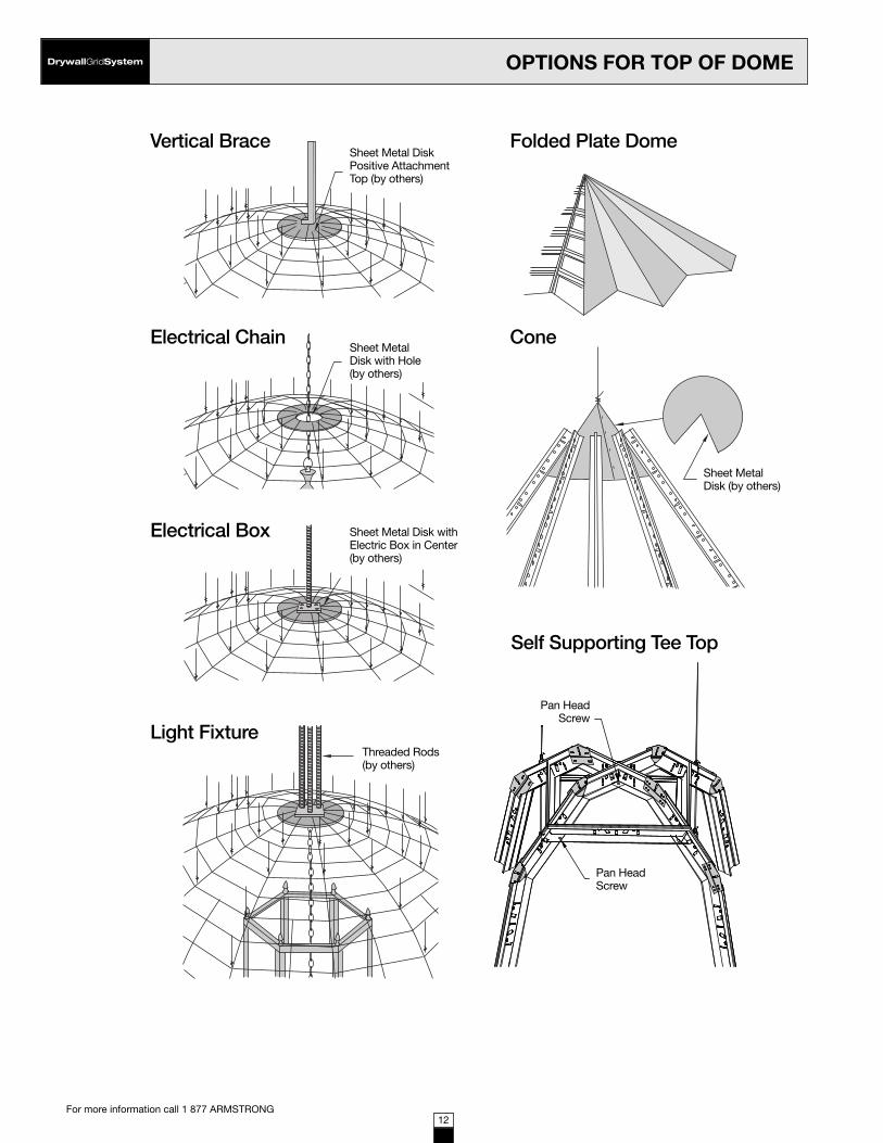
DrywallGridSystem OPTIONS FOR TOP OF DOME
For more information call 1 877 ARMSTRONG12
Vertical Brace Folded Plate Dome
Electrical Chain Cone
Electrical Box
Light Fixture
Self Supporting Tee Top
Sheet Metal DiskPositive AttachmentTop (by others)
Sheet MetalDisk with Hole(by others)
Sheet Metal Disk withElectric Box in Center(by others)
Sheet MetalDisk (by others)
Pan HeadScrew
Pan HeadScrew
Threaded Rods(by others)
3540 DomeCeilingsTG_310b 3/26/10 4:08 PM Page 12

DrywallGridSystem
For more information call 1 877 ARMSTRONG13
DOMES
13
Typical Details
Main BeamBoth Sidesof Panels
See page 15 for Bending Radius of gypsum board.
Main Beam
Main Beam
Hanger Wire 4'O.C. or less
Gypsum Wall Board
RadiusGypsumWall Board
Curved Angle Molding
RC2 Radius Clips
Radius GypsumWall Board
Dome with Skylight
3540 DomeCeilingsTG_310b 3/26/10 4:08 PM Page 13

14
DrywallGridSystem OTHER DOMES
For more information call 1 877 ARMSTRONG
CL
CL
CL
CL
CL
CL
Multi-Level Dome Egg or Elliptical Dome
Saucer Dome Up
Saucer Dome Down
Pole Dome
Saucer Dome Step Up Dome
Checker Board Dome(step down)
Offset 2 way Radius DomeColumn Ring Made from a Metal Angle
3540 DomeCeilingsTG_310b 3/26/10 4:08 PM Page 14

MaterialMinimum
Radius (dry)
Drywall Bending Radii
Maximum Cross TeeSpacing (wet)
Water Required Per Panel (oz.)
Maximum Cross TeeSpacing (dry)
MinimumRadius (wet)
1/4" Hi-flex Gypsum 32" 9" 20" concave14" convex
8" concave6" convex
1/4" Gypsum 5' 8" 2' 6" 30 ounces
3/8" Gypsum 7-1/2' 3' 8" 35 ounces
1/2" Gypsum 20' 16" 4' 12" 45 ounces
5/8" Gypsum 28' 24"
DrywallGridSystemFINISHING AND EXTERIOR APPLICATION
For more information call 1 877 ARMSTRONG15
Control JointsControl joints minimize cracking caused by stresses in the surface material attached to a metalsuspension system. Materials have different rates of expansion and control joints are placed 35'to 50' apart to control bucking and cracking of surface. Control joints are also used to minimizestresses in monolithic ceiling membrane that occur at columns, access doors, light fixtures, insideand outside corners and other unusual penetrations in ceilings.
Expansion JointsCeiling expansion joints are installed to separate the metal suspension system when expansionjoints occur in buildings, when span is over 100' or when metal changes direction. Expansionjoints are required to separate a system in T, H, L and U or Circle shaped buildings to eliminatecracking from expansion. Expansion and control joints look similar but perform different functions.
NOTE: Refer to gypsum wallboard manufacturer for additional information.
If required, apply water to the side of the panel that will be in compression. Apply the water uniformly over the surface of the boards. Stackmoistened boards on a flat surface and cover with plastic sheeting. Allow water to soak into the panels for at least one hour before applicationto the frame. Allow installed panels to dry for 24 hours before finishing.
Drywall Bending Radius
Non-Module Cut and Screw Application Metalto Metal
3540 DomeCeilingsTG_310b 3/26/10 4:08 PM Page 15

For more information call 1 877 ARMSTRONG16
DrywallGridSystem RADIUS IN FEET2'
Incr
emen
ts f
rom
Cen
ter
line Radius Dimension
10' 0" 11' 0" 12' 0" 13' 0" 14' 0" 15' 0" 16' 0" 17' 0" 18' 0" 19' 0" 20' 0" 21' 0" 22' 0" 23' 0" 24' 0"
2' 2" 2-1/4" 2" 1-7/8" 1-3/4" 1-5/8" 1-1/2" 1-1/2" 1-3/8" 1-1/4" 1-1/4" 1-1/8" 1-1/8" 1-1/8" 1"
4' 10" 9-1/8" 8-1/4" 7-5/8" 7" 6-1/2" 6-1/8" 5-3/4" 5-3/8" 5-1/8" 4-7/8" 4-5/8" 4-3/8" 4-1/4" 4"
6' 2'0" 1'9-3/8" 1'7-3/8" 1'5-5/8" 1'4-1/4" 1'3" 1'2" 1'1-1/8" 1'0-3/8" 11-3/4" 11-1/8" 10-1/2" 10" 9-5/8" 9-1/8"
8' 4'0" 3'5-5/8" 3'0-3/4" 2'9-1/8" 2'6-1/8" 2'3-3/4" 2'1-3/4" 2'0" 1'10-1/2" 1'9-1/4" 1'8-1/8" 1'7" 1'6-1/8" 1'5-1/4" 1'4-1/2"
25' 0" 26' 0" 27' 0" 28' 0" 29' 0" 30' 0" 31' 0" 32' 0" 33' 0" 34' 0" 35' 0" 36' 0" 37' 0" 38' 0" 39' 0"
2' 1" 1" 7/8" 7/8" 7/8" 7/8" 3/4" 3/4" 3/4" 3/4" 3/4" 3/4" 5/8" 5/8" 5/8"
4' 3-7/8" 3-3/4" 35/8" 3-1/2" 3-3/8" 3-1/4" 3-1/8" 3" 3" 2-7/8" 2-3/4" 2-3/4" 2-5/8" 2-5/8" 2-1/2"
6' 8-3/4" 8-1/2" 81/2" 7-7/8" 7-1/2" 7-1/4" 7-1/8" 6-7/8" 6-5/8" 6-3/8" 6-1/4" 6-1/8" 5-7/8" 5-3/4" 5-5/8"
8' 1'3-3/4" 1'3-1/8" 1'25/8" 1'2" 1'2-1/2" 1'1-1/8" 1'0-5/8" 1'0-1/4 " 11-1/2" 11-1/2" 11-1/8" 10-7/8" 10-1/2" 10-1/4" 10"
40' 0" 41' 0" 42' 0" 43' 0" 44' 0" 45' 0" 46' 0" 47' 0" 48' 0" 49' 0" 50' 0" 51' 0" 52' 0" 53' 0" 54' 0"
2' 5/8" 5/8" 5/8" 5/8" 5/8" 5/8" 1/2" 1/2" 1/2" 1/2" 1/2" 1/2" 1/2" 1/2" 1/2"
4' 2-3/8" 2-3/8" 2-3/8" 2-1/4" 2-1/8" 2-1/8" 2-1/8" 2-1/8" 2" 2" 2" 1-7/8" 1-7/8" 1-3/4" 1-3/4"
6' 5-1/2" 5-3/8" 5-1/4" 5-1/8" 5" 4-7/8" 4-3/4" 4-5/8" 4-1/2" 4-1/2" 4-3/8" 4-1/4" 4-1/4" 4-1/4" 4"
8' 9-3/4" 9-1/2" 9-1/4" 9" 8-7/8" 8-5/8" 8-1/2" 8-1/4 " 8-1/8" 7-7/8" 7-3/4" 7-5/8" 7-1/2" 7-3/8" 7-1/8"
55' 0" 56' 0" 57' 0" 58' 0" 59' 0" 60' 0" 61' 0" 62' 0" 63' 0" 64' 0" 65' 0" 66' 0" 67' 0" 68' 0" 69' 0"
2' 1/2" 1/2" 1/2" 1/2" 1/2" 3/8" 3/8" 3/8" 3/8" 3/8" 3/8" 3/8" 3/8" 3/8" 3/8"
4' 1-3/4" 1-3/4" 1-3/4" 1-3/4" 1-5/8" 1-5/8" 1-5/8" 1-5/8" 1-1/2" 1-1/2" 1-1/2" 1-1/2" 1-1/2" 1-1/2" 1-3/8"
6' 4" 3-7/8" 3-7/8" 3-3/4" 3-3/4" 3-5/8" 3-5/8" 3-1/2" 3-1/2" 3-3/8" 3-3/8" 3-1/4" 3-1/4" 3-1/4" 3-1/8"
8' 7" 6-7/8" 6-3/4" 6-5/8" 6-5/8" 6-1/2" 6-3/8" 6-1/4 " 6-1/8" 6" 6" 5-7/8" 5-3/4" 5-3/4" 5-5/8"
70' 0" 71' 0" 72' 0" 73' 0" 74' 0" 75' 0" 76' 0" 77' 0" 78' 0" 79' 0" 80' 0" 81' 0" 82' 0" 83' 0" 84' 0"
2' 3/8" 3/8" 3/8" 3/8" 3/8" 3/8" 3/8" 3/8" 3/8" 3/8" 3/8" 3/8" 3/8" 3/8" 3/8"
4' 1-3/8" 1-3/8" 1-3/8" 1-3/8" 1-3/8" 1-1/4" 1-1/4" 1-1/4" 1-1/4" 1-1/4" 1-1/4" 1-1/4" 1-1/4" 1-1/4" 1-1/8"
6' 3-1/8" 3-1/8" 3" 3" 3" 2-7/8" 2-7/8" 2-7/8" 2-3/4" 2-3/4" 2-3/4" 2-3/4" 2-5/8" 2-5/8" 2-5/8"
8' 5-1/2" 5-1/2" 5-3/8" 5-1/4" 5-1/4" 5-1/8" 5-1/8" 5" 5" 4-7/8" 4-7/8" 4-3/4" 4-3/4" 4-5/8" 4-5/8"
85' 0" 86' 0" 87' 0" 88' 0" 89' 0" 90' 0" 91' 0" 92' 0" 93' 0" 94' 0" 95' 0" 96' 0" 97' 0" 98' 0" 99' 0"
2' 3/8" 1/4" 1/4" 1/4" 1/4" 1/4" 1/4 1/4" 1/4" 1/4" 1/4" 1/4" 1/4" 1/4" 1/4"
4 1-1/8" 1-1/8" 1-1/8" 1-1/8" 1-1/8" 1-1/8" 1-1/8 1-1/8" 1-1/8" 1" 1" 1" 1" 1" 1"
6' 2-5/8" 2-1/2" 2-1/2" 2-1/2" 2-1/2" 2-3/8" 2-3/8 2-3/8" 2-3/8" 2-3/8" 2-1/4" 2-1/4" 2-1/4" 2-1/4" 2-1/4"
8' 4-1/2" 4-1/2" 4-1/2" 4-3/8" 4-3/8" 4-1/4" 4-1/4 4-1/4" 4-1/8" 4-1/8" 4-1/8" 4" 4" 4" 3-7/8"
100' 0" 105' 0" 110' 0" 115' 0" 120' 0" 125' 0" 130' 0" 135' 0" 140' 0" 145' 0" 150' 0" 155' 0" 160' 0" 165' 0" 170' 0"
2' 1/4" 1/4" 1/4" 1/4" 1/4" 1/4" 1/4" 1/4" 1/4" 1/4" 1/4" 1/4" 1/8" 1/8" 1/8"
4' 1" 1" 7/8" 7/8" 7/8" 3/4" 3/4" 3/4" 3/4" 3/4" 5/8" 5/8" 5/8" 5/8" 5/8"
6' 2-1/4" 2-1/8" 2" 1-7/8" 1-7/8" 1-3/4" 1-3/4" 1-5/8" 1-5/8" 1-1/2" 1-1/2" 1-3/8" 1-3/8" 1-3/8" 1-1/4"
8' 3-7/8" 3-3/4" 3-1/2" 3-3/8" 3-1/4" 3-1/8" 3" 2-7/8" 2-3/4" 2-3/4" 2-5/8" 2-1/2" 2-3/8" 2-3/8 2-1/4"
175' 0" 180' 0" 185' 0" 190' 0" 195' 0" 200' 0" 210' 0" 220' 0" 230' 0" 240' 0" 250' 0"
2' 1/8" 1/8" 1/8" 1/8" 1/8" 1/8" 1/8" 1/8" 1/8" 1/8" 1/8"
4' 5/8" 5/8" 1/2" 1/2" 1/2" 1/2" 1/2" 1/2" 3/8" 3/8" 3/8"
6' 1-1/4" 1-1/4" 1-1/4" 1-1/8" 1-1/8" 1-1/8" 1" 1" 1" 7/8" 7/8"
8' 2-1/4" 2-1/8" 2-1/8" 2" 2" 2" 1-7/8" 1-3/4" 1-5/8" 1-5/8" 1-1/2"
3540 DomeCeilingsTG_310b 3/26/10 4:08 PM Page 16

On Center Spacingof Component
Percent ofSquare Footage
8" 108%
12" 100%
16" 76%
20" 60%
24" 50%
30" 40%
36" 33%
48" 25%
60" 20%
** Dimensions are nominal.
DrywallGridSystemESTIMATING MATERIAL
For more information call 1 877 ARMSTRONG17
Example calculation based on 5,100 SF ceiling:Main beam at 48″ O.C.
5,100 SF x .25 = 1,275 LF1,275 LF ÷ 144 LF/Ctn = 9 cartons needed
Cross tee at 16″ O.C.5,100 SF x .76 = 3,876 LF3,876 LF ÷ 144 LF/Ctn = 27 cartons needed
Estimating Lineal Feet of Grid Based on Square Footage of Ceiling
Item # Length Pcs/Ctn. LF/Ctn. Lbs./Ctn. Area of ceiling completed by one carton
REVERSE MOLDINGS16"O.C.
24"O.C.
7857 120" 30 360 51 sq.ft.
7858 120" 20 240 67
DRYWALL UNHEMMEDCHANNEL MOLDING
7838 120" 20 200 36
DRYWALL ANGLE MOLDING
HD7801G90 120" 30 300 38
KAM-12 144" 30 360 31
KAM-10 120" 30 300 49
LAM-12 144" 30 360 31
Item # Length Pcs/Ctn. LF/Ctn. Lbs./Ctn. Area of ceiling completed by one carton
DRYWALL/STUCCOGRID MAIN BEAM
8"O.C.
16"O.C.
24"O.C.
36"O.C.
48"O.C.
50"O.C.
HD8901 144" 20 240 71 480 720 960 1000 sq.ft.
HD8906/HD8906G90 144" 12 144 53 288 432 576 600 sq.ft.
HD8906F08/HD8906F16 144" 12 144 53 sq.ft.
DRYWALL/STUCCO GRID 1-1/2" FACE CROSS TEES
8"O.C.
16"O.C.
24"O.C.
XL8965 72" 36 216 78 144 288 432 sq.ft.
XL8947P/XL8947PG90** 50" 36 150 56 100 200 300 sq.ft.
XL8945P/XL8945PG90 48" 36 144 52 96 192 288 sq.ft.
XL7936G90 36" 36 108 39 144 216 sq.ft.
XL8925/XL8925G90** 26" 36 78 28 sq.ft.
XL8926/XL8926G90 24" 36 72 26 48 sq.ft.
XL7918** 14" 36 42 14 sq.ft.
DRYWALL/STUCCO GRID15/16" FACE CROSS TEES
8"O.C.
16"O.C.
24"O.C.
XL7341/XL8341 48" 60 240 71 72 320 480 sq.ft.
3540 DomeCeilingsTG_310b 3/26/10 4:08 PM Page 17

CEILING SYSTEMS
1 877 ARMSTRONG (1 877 276-7876)• Name of your Inner Circle Contractor or
Gold Circle Distributor or Sales Representative• Customer Service Representatives
7:30 a.m. to 5:00 p.m. EST, Monday through Friday• TechLine
SM— Technical information —
7:45 a.m. to 5:30 p.m. EST, Monday through Friday FAX 1-800-572-8324 or email: [email protected]
• Product literature and samples — Express service or regular delivery
• Request a personal copy of the Armstrong Ceiling Systems catalog
armstrong.com/drywallgrid• Latest product and program news• Real time selection and technical information• Contacts — reps, where to buy, how to install• Submittal pages• Literature and samples information• CAD renderings
These drawings show typical conditions in which the Arm-strong product depicted is installed. They are not a substi-tute for an architect’s or engineer’s plan and do not reflect the unique requirements of local building codes,laws, statutes, ordinances, rules and regulations (LegalRequirements) that may be applicable for a particular installation.
Armstrong does not warrant, and assumes no liability for the accuracy or completeness of the drawings for a particular installation or their fitness for a particular purpose. The user is advised to consult with a duly li-censed architect or engineer in the particular locale of the installation to assure compliance with all Legal Requirements.
Armstrong is not licensed to provide professional architecture or engineering design services.
Engineering data included provided by outside engineering company.
CS-3590 -Drywall FramingSystems
CS-3542 - Synthetic Stucco Grid Systems
CS-3541 -Stucco/Plaster GridSystems
CS-3539 - Drywall Grid Systemsfor Flat Applications
Additional Drywall Grid Systems are available. For more information, visit armstrong.com/drywallgrid or call 877-ARMSTRONG to request literature.
For more information call 1 877 ARMSTRONG
© AWI Licensing Company, 2010Printed in United States of America
CS-3540-310
3540 DomeCeilingsTG_310b 3/26/10 4:08 PM Page 18