hands on relay school, march 2018 synchrophasors · real time pricing / tariffs . ... faut l...
TRANSCRIPT

HANDS ON RELAY SCHOOL, MARCH 2018
SYNCHROPHASORS DEFINITIONS, FUNCTIONALITY AND STANDARDS Galina S. Ant onova , Technica l Sa les Eng ineer

Int roduct ion
Synchrop has or t echno log y
Synchrop has or d efinit ion
Synchrop has or t e rm ino log y
Synchrop has or s ys t em s
Phas or Meas urem ent Unit s (PMUs )
Synchrop has or s t and a rd s
Synchrop has or exercis es
Conclus ions
Slid e 2
Agenda
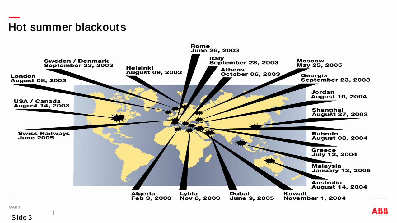
Hot summer blackout s
Slide 3

Sept ember 2011 Sout hwest US Out age
Source: NERC Recommendations from 2011 Southwest Outage May 8 2012 Slide 4
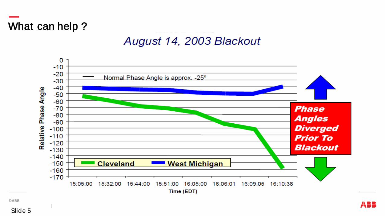
What can help ?
Slide 5

Power Syst ems Challenges and Solut ions
1) Int egrat ion of renewables Remot e grid operat ion wit h dist ribut ed generat ion (wind/ solar farms) Increase grid capacit y and st abilit y Balance load t o supply 2) Int egrat ion of elect ric vehicles Charging / billing Energy st orage Load management 3) Demand response Real t ime pricing / t arif fs Home aut omat ion / load management Dist ribut ed generat ion / st orage 4) Reliabilit y and ef f iciency cyber securit y cust omer out age informat ion emergency / peak power
2
2
3
3
4 4
4
Applicat ions and t echnologies Gat eways wit h bi-direct ional communicat ion for consumer int eract ion Smart met ers, Int ernet / mobile t elecom, smart houses Cust omer service syst ems including billing Fault det ect ion, isolat ion and rest orat ion; volt age opt imizat ion FACTS, HVDC, WAMS WAMPACS
1
1
1
1
Slid e 6
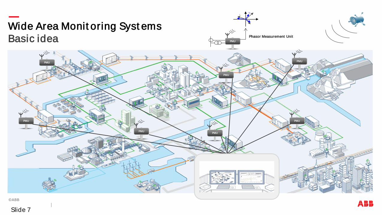
Wide Area Monit oring Syst ems Basic idea
PMU
PMU
PMU
PMU
PMU
PMU
PMU
PMU
Phasor Measurement Unit
U1 I3
Slide 7
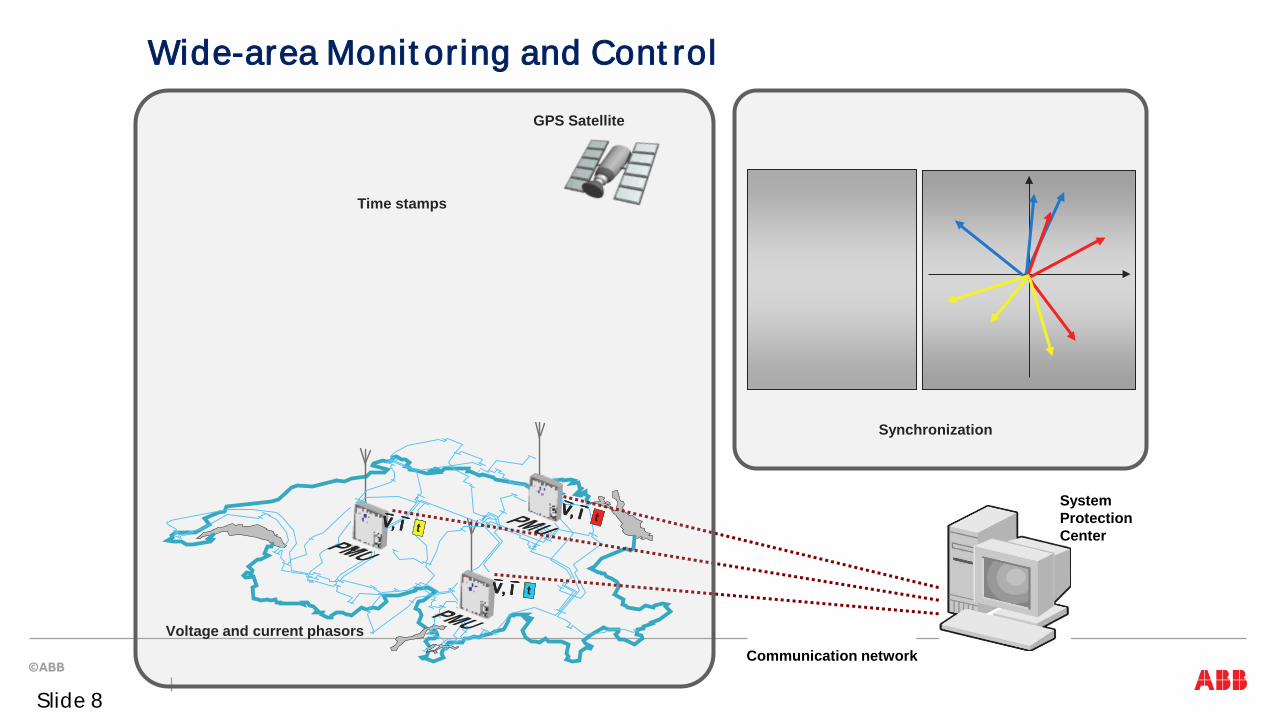
Time stamps
GPS Satellite
Voltage and current phasors
Synchronization
Communication network
Wide-area Monit oring and Cont rol
System Protection Center
Slide 8
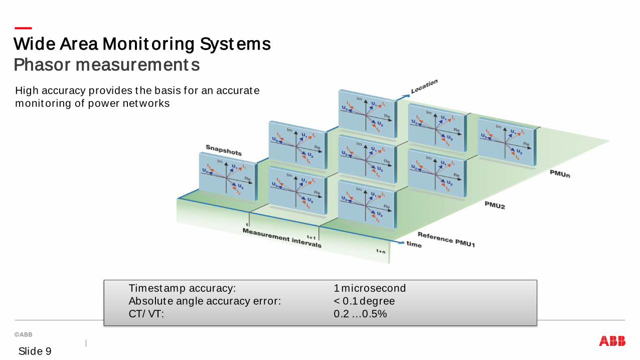
Wide Area Monit oring Syst ems Phasor measurement s
Timestamp accuracy: 1 microsecond Absolute angle accuracy error: < 0.1 degree CT/ VT: 0.2 …0.5%
High accuracy provides t he basis for an accurate monit oring of power networks
Slide 9
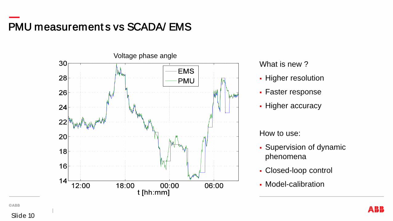
PMU measurement s vs SCADA/ EMS
Voltage phase angle What is new ?
Higher resolution
Faster response
Higher accuracy
How to use:
Supervision of dynamic phenomena
Closed-loop control
Model-calibration
Slide 10
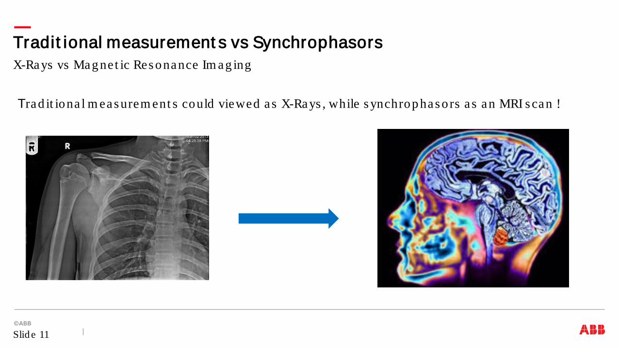
Trad it iona l m eas urem ent s could viewed as X-Rays , while s ynchrop has ors a s an MRI s can !
X-Rays vs Mag net ic Res onance Im ag ing Tradit ional measurement s vs Synchrophasors
Slid e 11
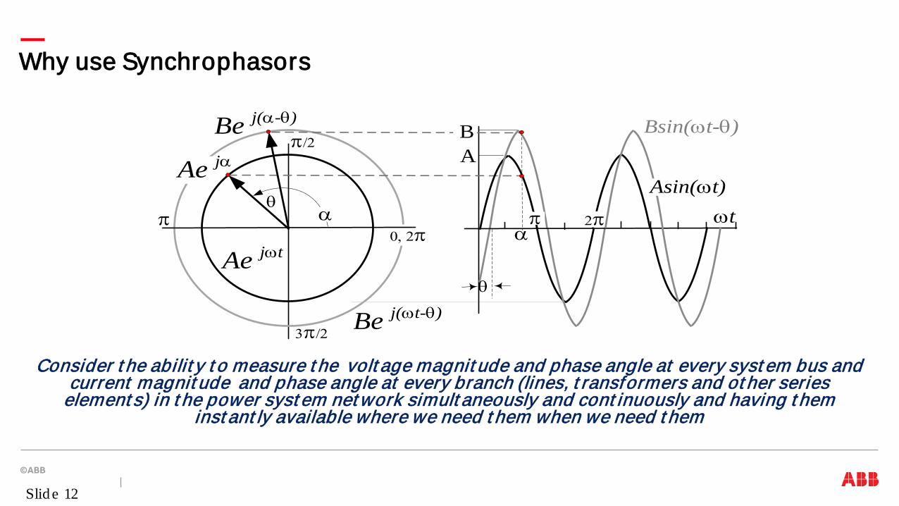
Why use Synchrophasors
Consider t he abilit y t o measure t he volt age magnit ude and phase angle at every syst em bus and current magnit ude and phase angle at every branch (lines, t ransformers and ot her series
element s) in t he power syst em net work simult aneously and cont inuously and having t hem inst ant ly available where we need t hem when we need t hem
Be j(ωt-θ)
Ae jωt
Be j(α-θ)
Ae jα
α
Bsin(ωt-θ)
π
π/2
3π/2
0, 2π
AB
θ
θ
α π 2π
Asin(ωt)ωt
Slid e 12

What is Phasor ?
.
A complex number t hat represent s t he phase and magnit ude of an AC waveform
Xm cos (2 π 60 t + φ) Xm/√2 ejφ
-1
-0.5
0
0.5
1
-50 0 50 100 150 200 250 300 350 400
φ φ
Xm
Xm/√2
Slid e 13
What is Phasor ?
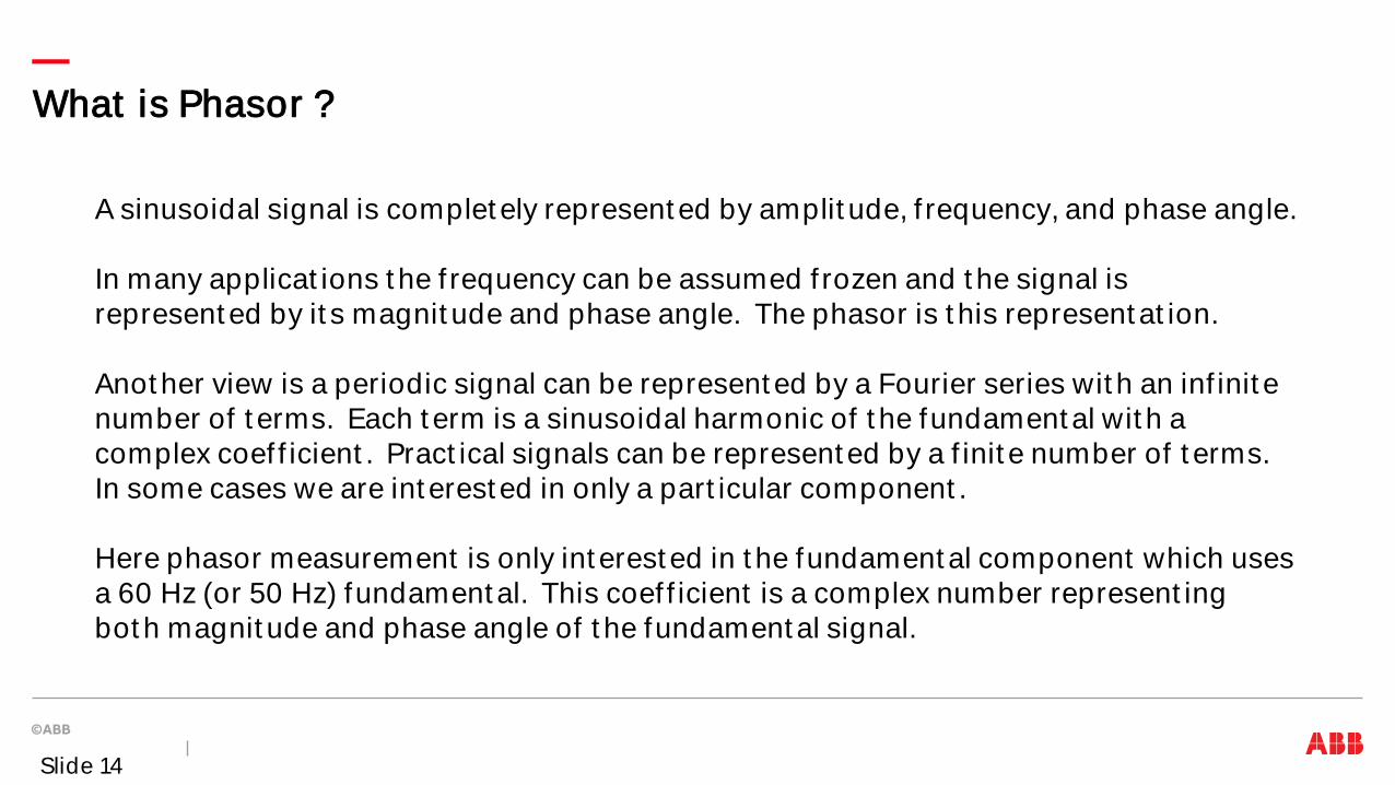
A sinusoidal signal is complet ely represent ed by amplit ude, f requency, and phase angle. In many applicat ions t he f requency can be assumed f rozen and t he signal is represent ed by it s magnit ude and phase angle. The phasor is t his represent at ion. Anot her view is a periodic signal can be represent ed by a Fourier series wit h an inf init e number of t erms. Each t erm is a sinusoidal harmonic of t he fundament al wit h a complex coef f icient . Pract ical signals can be represent ed by a f init e number of t erms. In some cases we are int erest ed in only a part icular component . Here phasor measurement is only int erest ed in t he fundament al component which uses a 60 Hz (or 50 Hz) fundament al. This coef f icient is a complex number represent ing bot h magnit ude and phase angle of t he fundament al signal.
Slide 14
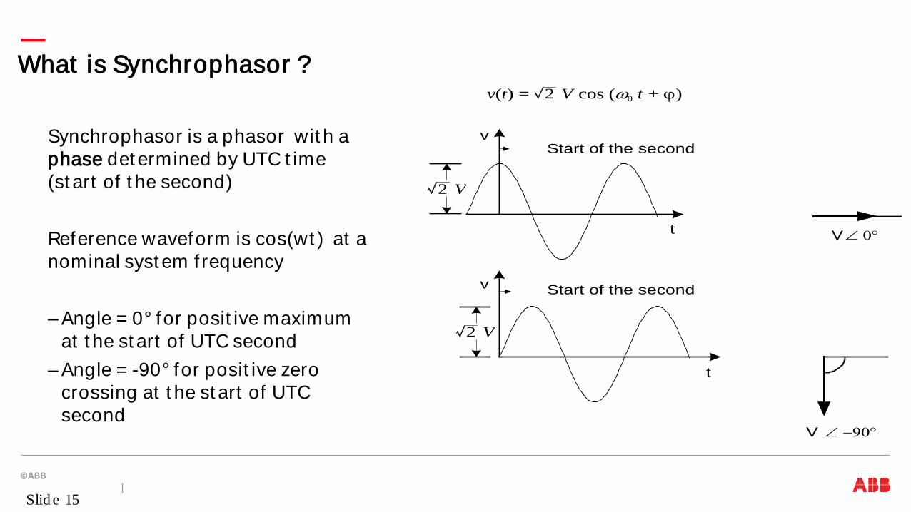
What is Synchrophasor ?
Synchrophasor is a phasor wit h a phase det ermined by UTC t ime (st art of t he second) Reference waveform is cos(wt ) at a nominal syst em f requency – Angle = 0° for posit ive maximum
at t he st art of UTC second – Angle = -90° for posit ive zero
crossing at t he st art of UTC second
V ∠ 0°
V ∠ −90°
Start of the second
Start of the second
t
t
v
v
2 V
2 V
v(t) = 2 V cos (ω0 t + ϕ)
Slid e 15
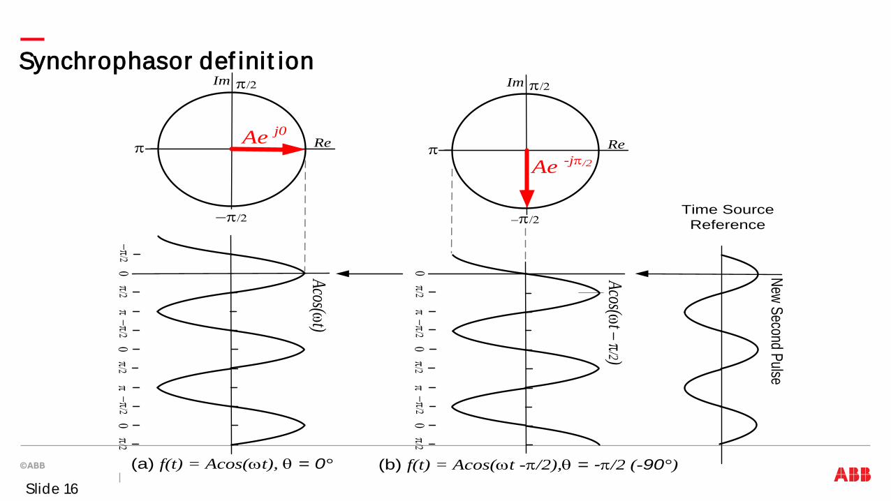
Synchrophasor def init ion
Ae j0
Acos(ωt)
Acos(ωt – π/2)
−π/2π/2
π0
−π/2π/2
π0
−π/2π/2
0
π/2π
0−π/2
π/2π
0−π/2
π/20
π
−π/2
Im
Re
Ae -jπ/2π
−π/2
Im
Re
(a) f(t) = Acos(ωt), θ = 0° (b) f(t) = Acos(ωt -π/2),θ = -π/2 (-90°)
Time Source Reference
New Second Pulse
π/2 π/2
Slide 16

Accuracy of t he s ynchrop has or m eas urem ent is d efined a s 1% Tot a l Vect o r Erro r All p has or m eas urem ent unit im p lem ent a t ions m us t t his crit e ria
Accuracy o f s ynchrop has or m eas urem ent Concept of Tot al Vect or Error
Slid e 17
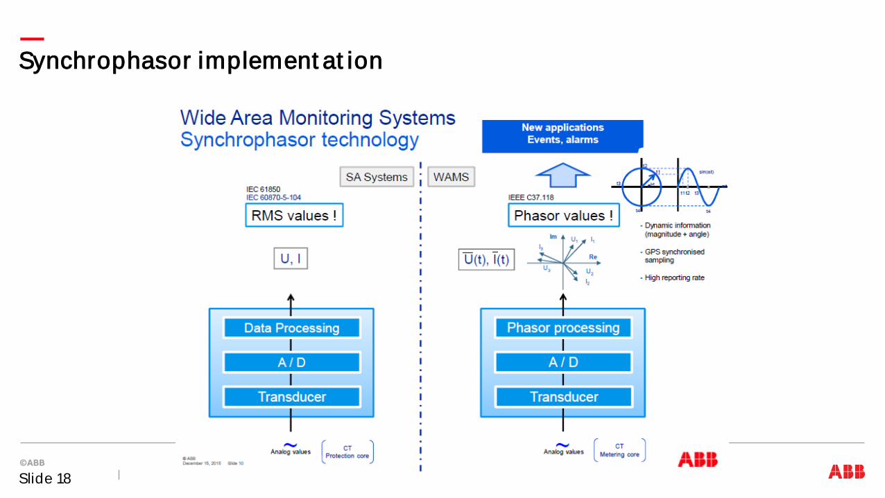
Synchrophasor implement at ion
Slide 18
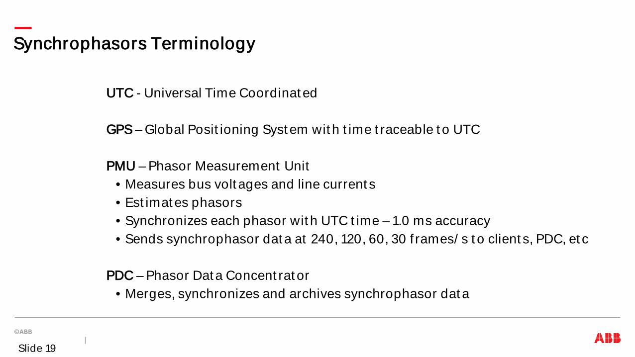
Synchrophasors Terminology
UTC - Universal Time Coordinat ed GPS – Global Posit ioning Syst em wit h t ime t raceable t o UTC PMU – Phasor Measurement Unit
• Measures bus volt ages and line current s • Est imat es phasors • Synchronizes each phasor wit h UTC t ime – 1.0 ms accuracy • Sends synchrophasor dat a at 240, 120, 60, 30 f rames/ s t o client s, PDC, et c
PDC – Phasor Dat a Concent rat or
• Merges, synchronizes and archives synchrophasor dat a
Slide 19
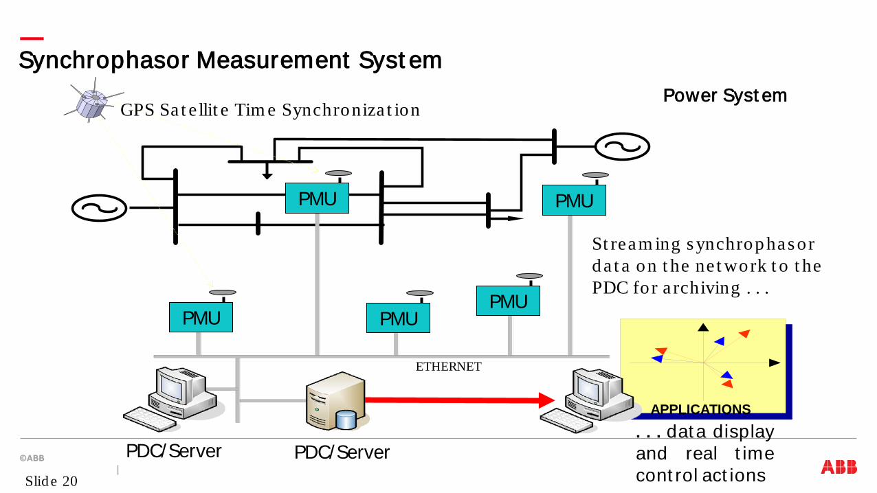
Synchrophasor Measurement Syst em
APPLICATIONS . . . data display and real t ime cont rol act ions
Power Syst em
PDC/Server PDC/Server
ETHERNET
St ream ing s ynchrop has or d a t a on t he ne t work t o t he PDC fo r a rchiving . . .
GPS Sa t e llit e Tim e Synchroniza t ion
PMU
PMU PMU PMU
PMU
Slid e 20
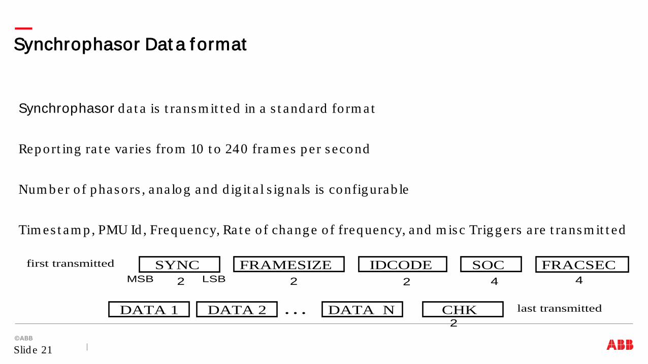
Synchrophasor d a t a is t rans m it t ed in a s t and a rd fo rm a t Rep ort ing ra t e va ries from 10 t o 240 fram es p er s econd Num b er o f p has ors , ana log and d ig it a l s ig na ls is config urab le Tim es t am p , PMU Id , Freq uency, Ra t e o f chang e o f freq uency, and m is c Trig g ers a re t rans m it t ed
Synchrophasor Dat a f ormat
Slid e 21
first transmitted
last transmitted . . .
4 2
2
MSB LSB
DATA 1
FRAMESIZE SOC SYNC 2
DATA 2 DATA N CHK
IDCODE 2
FRACSEC 4

Various communicat ion int erfaces and prot ocols can be used Seria l RS232 int erface is s t ill s up p ort ed wit h up t o 60 fram es p er s econd Et hernet int erface is m os t com m on, e lect rica l o r op t ica l Et hernet (RJ45, LC, ST connect o rs ) Pro t ocols s up p ort ed a re TCP and UDP over IP Different p ro t ocols can b e us ed fo r s end ing Com m and s and Da t a
• Com m and s a re t yp ica lly s ent over TCP, a s it is m ore re liab le) • Dat a can b e s ent over TCP or UDP
UDP t rans m is s ions have an ad vant ag e o f one t o m any m od e, ca lled m ult icas t
Synchrophasor Communicat ion opt ions
Slid e 22
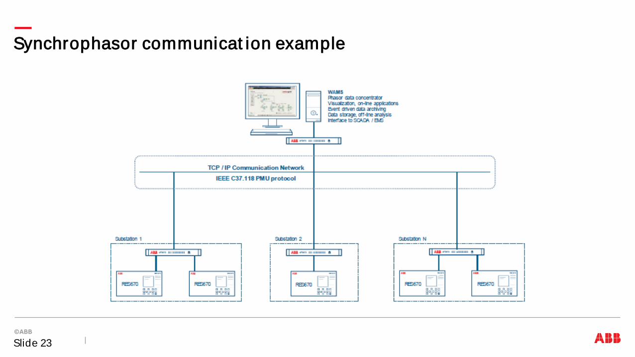
Synchrophasor communicat ion example
Slide 23
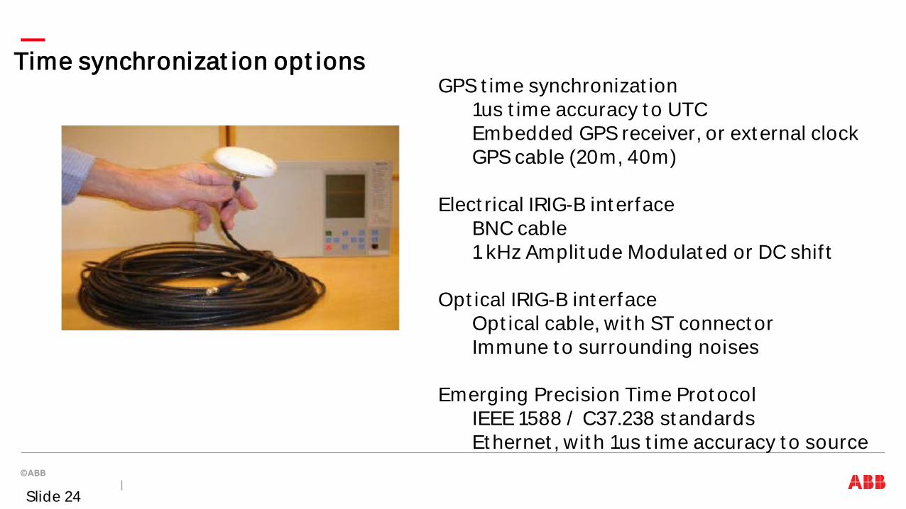
Time synchronizat ion opt ions GPS t ime synchronizat ion
1us t ime accuracy t o UTC Embedded GPS receiver, or ext ernal clock GPS cable (20m, 40m)
Elect rical IRIG-B int erface BNC cable 1 kHz Amplit ude Modulat ed or DC shif t
Opt ical IRIG-B int erface Opt ical cable, wit h ST connect or Immune t o surrounding noises
Emerging Precision Time Prot ocol IEEE 1588 / C37.238 st andards Et hernet , wit h 1us t ime accuracy t o source
Slide 24

Wide Area Monit oring Syst ems PSGuard and RES670
Slide 25
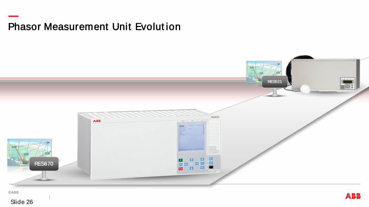
Phasor Measurement Unit Evolut ion
RES670
RES521
Slide 26
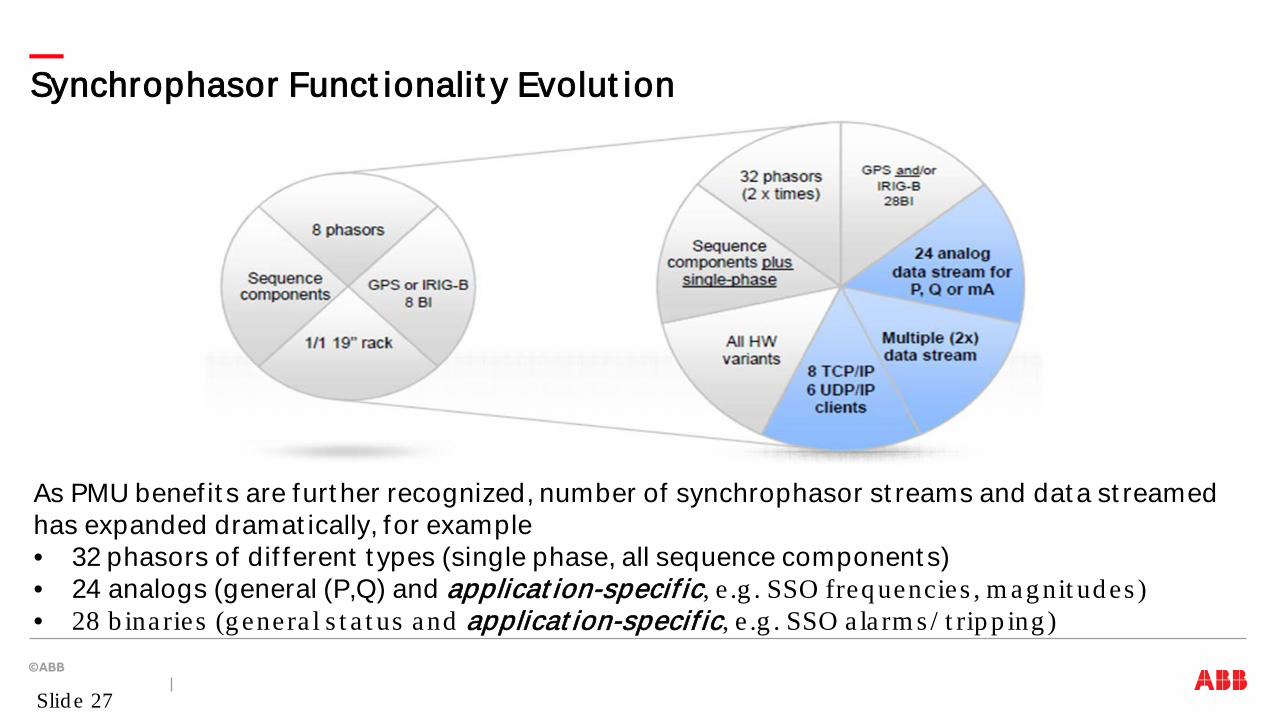
Synchrophasor Funct ionalit y Evolut ion
As PMU benef it s are furt her recognized, number of synchrophasor st reams and dat a st reamed has expanded dramat ically, for example • 32 phasors of dif ferent t ypes (single phase, all sequence component s) • 24 analogs (general (P,Q) and applicat ion-specif ic, e .g . SSO freq uencies , m ag nit ud es ) • 28 b ina ries (g enera l s t a t us and applicat ion-specif ic, e .g . SSO a la rm s / t rip p ing )
Slid e 27
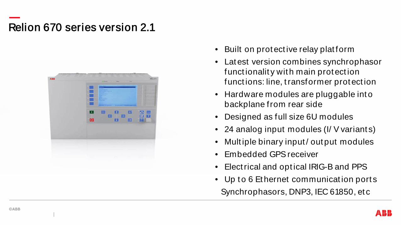
Relion 670 series version 2.1
• Built on prot ect ive relay plat form • Lat est version combines synchrophasor
funct ionalit y wit h main prot ect ion funct ions: line, t ransformer prot ect ion
• Hardware modules are pluggable int o backplane f rom rear side
• Designed as full size 6U modules • 24 analog input modules (I/ V variant s) • Mult iple binary input / out put modules • Embedded GPS receiver • Elect rical and opt ical IRIG-B and PPS • Up t o 6 Et hernet communicat ion port s
Synchrophasors, DNP3, IEC 61850, et c
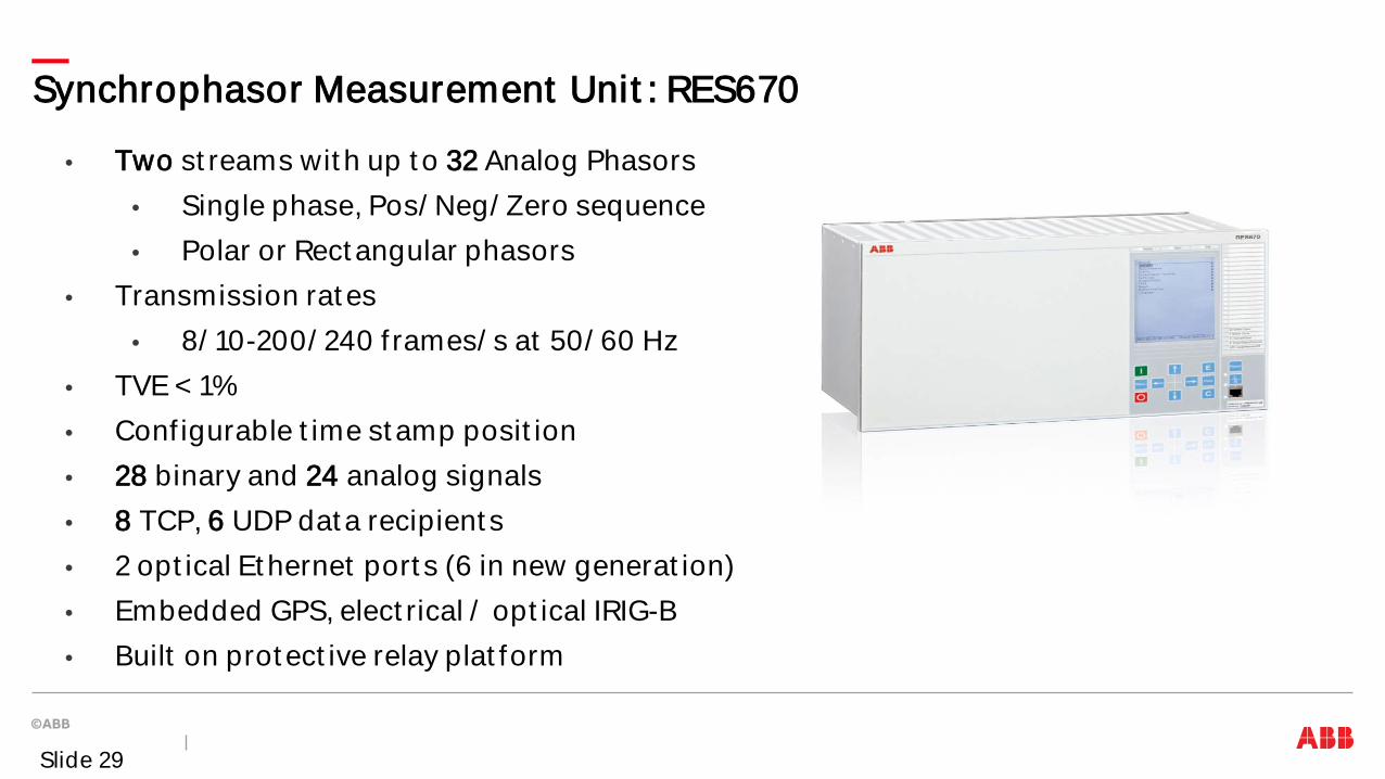
• Two st reams wit h up t o 32 Analog Phasors • Single phase, Pos/ Neg/ Zero sequence • Polar or Rect angular phasors
• Transmission rat es • 8/ 10-200/ 240 f rames/ s at 50/ 60 Hz
• TVE < 1% • Conf igurable t ime st amp posit ion • 28 binary and 24 analog signals • 8 TCP, 6 UDP dat a recipient s • 2 opt ical Et hernet port s (6 in new generat ion) • Embedded GPS, elect rical / opt ical IRIG-B • Built on prot ect ive relay plat form
Synchrophasor Measurement Unit : RES670
Slide 29
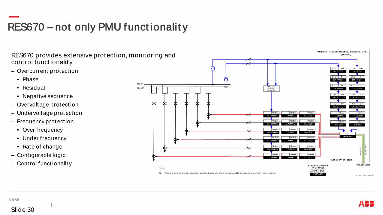
RES670 – not only PMU funct ionalit y
RES670 provides extensive protect ion, monit oring and cont rol funct ionalit y – Overcurrent prot ect ion
• Phase • Residual • Negat ive sequence
– Overvolt age prot ect ion – Undervolt age prot ect ion – Frequency prot ect ion
• Over f requency • Under f requency • Rat e of change
– Conf igurable logic – Cont rol funct ionalit y
Slide 30
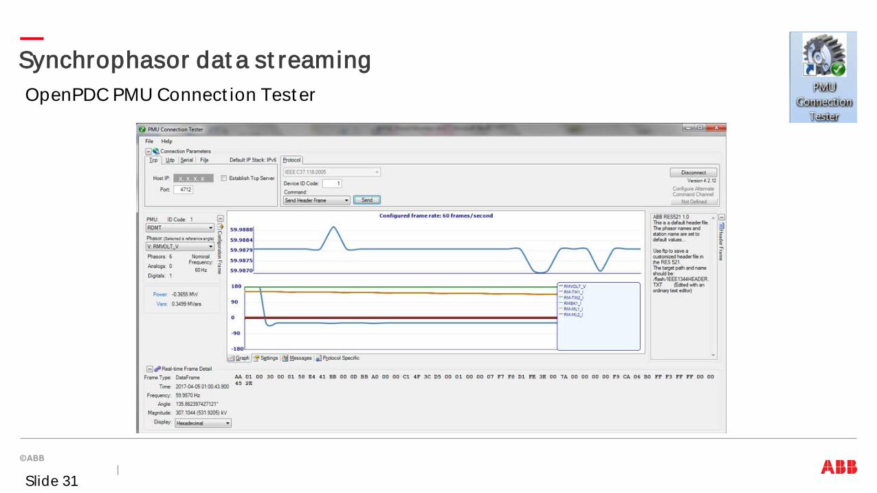
Synchrophasor dat a st reaming
Slide 31
OpenPDC PMU Connect ion Test er
x. x. x. x

Synchrophasor St andardizat ion
IEEE 1344-1995 Synchrophasor st andard superseded by IEEE C37.118-2005 IEEE C37.118-2005 Synchrophasor st andard superseded by – IEEE C37.118.1-2011 St andard for Synchrophasor Measurement s – IEEE C37.118.2-2011 St andard for Synchrophasor Dat a Transfer – Amendment IEEE C37.118.1a-2014 IEC 61850-90-5 Technical Report for Synchrophasor Dat a Transfer over in IEC 61850 Joint IEC / IEEE 60255-118.1 St andard on synchrophasor measurement s (under IEC/ IEEE approvals)
Slide 32
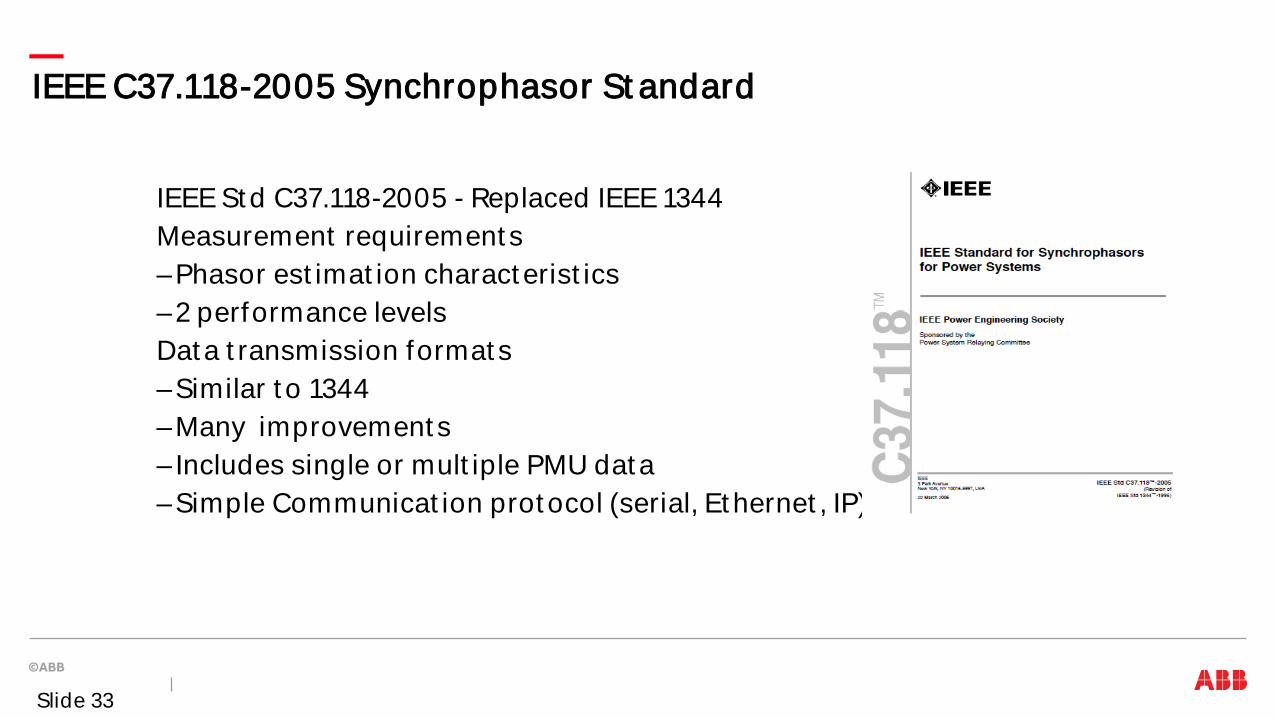
IEEE C37.118-2005 Synchrophasor St andard
IEEE St d C37.118-2005 - Replaced IEEE 1344 Measurement requirement s –Phasor est imat ion charact erist ics –2 performance levels Dat a t ransmission format s –Similar t o 1344 –Many improvement s – Includes single or mult iple PMU dat a –Simple Communicat ion prot ocol (serial, Et hernet , IP)
Slide 33
IEEE C37.118.1/ 2-2011 St andards
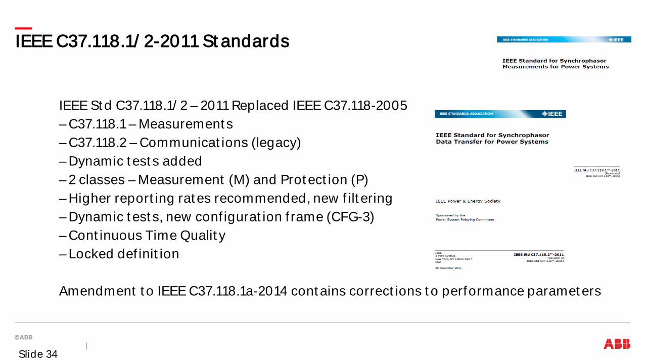
IEEE St d C37.118.1/ 2 – 2011 Replaced IEEE C37.118-2005 – C37.118.1 – Measurement s – C37.118.2 – Communicat ions (legacy) – Dynamic t est s added – 2 classes – Measurement (M) and Prot ect ion (P) – Higher report ing rat es recommended, new f ilt ering – Dynamic t est s, new conf igurat ion f rame (CFG-3) – Cont inuous Time Qualit y – Locked def init ion
Amendment t o IEEE C37.118.1a-2014 cont ains correct ions t o performance paramet ers
Slide 34
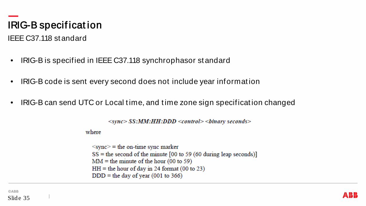
• IRIG-B is specif ied in IEEE C37.118 synchrophasor st andard • IRIG-B code is sent every second does not include year informat ion • IRIG-B can send UTC or Local t ime, and t ime zone sign specif icat ion changed
IEEE C37.118 st andard IRIG-B specif icat ion
Slid e 35
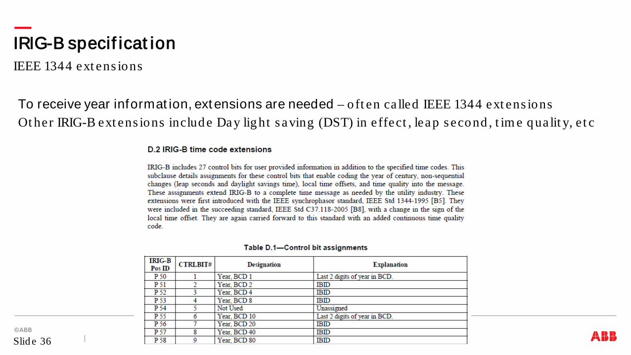
To receive year informat ion, ext ensions are needed – o ft en ca lled IEEE 1344 ext ens ions Ot her IRIG-B ext ens ions includ e Day lig ht s aving (DST) in effect , leap s econd , t im e q ua lit y, e t c
IEEE 1344 ext ens ions IRIG-B specif icat ion
Slid e 36
Ot her Synchrophasor St andards
IEC TR 61850-90-5 Approved and published in May 2012 – Transport of synchrophasor dat a – Int egrat ion wit h IEC 61850 syst ems – Rout able t ransport (t arget ed t o subst at ion t o subst at ion) – UDP t ransport , unicast and mult icast (preferred) – Securit y included – Mult iple communicat ions layers Joint IEC / IEEE 60255-118.1 st andard on synchrophasor measurement s is undergoing IEEE/ IEC approvals
Slide 37
IEEE Guides and Report s on Synchrophasors
IEEE PES PSRC Working Groups generat ed t he following document s IEEE Report Published in August 2013 Use of Synchrophasor Measurement s in Prot ect ive Relaying Applicat ions IEEE C37.242-2013 Published in March 2013 Guide for PMU Synchronizat ion, Calibrat ion, Test ing and Inst allat ion IEEE C37.244-2013 Published in May 2013 Guide for PDC Requirement s for Power Syst em Prot ect ion, Cont rol and Monit oring
Slide 38
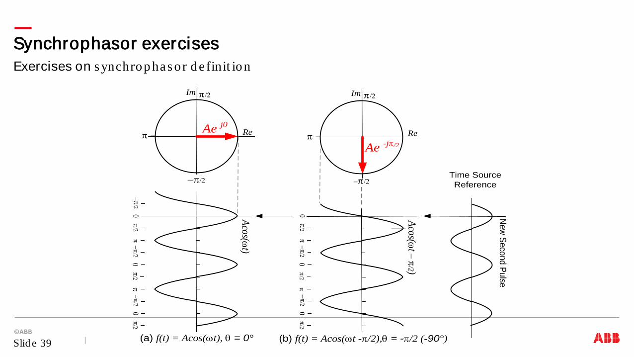
Exercises on s ynchrop has or d efinit ion Synchrophasor exercises
Slid e 39
Ae j0
Acos(ωt)
Acos(ωt – π/2)
−π/2π/2
π0
−π/2π/2
π0
−π/2π/2
0
π/2π
0−π/2
π/2π
0−π/2
π/20
π
−π/2
Im
Re
Ae -jπ/2π
−π/2
Im
Re
(a) f(t) = Acos(ωt), θ = 0° (b) f(t) = Acos(ωt -π/2),θ = -π/2 (-90°)
Time Source Reference
New Second Pulse
π/2 π/2
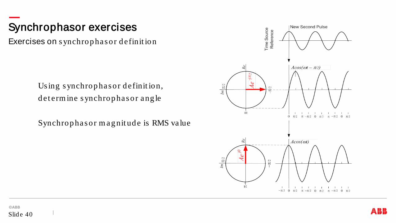
Exercises on s ynchrop has or d efinit ion Synchrophasor exercises
Slid e 40
Us ing s ynchrop has or d efinit ion, d e t erm ine s ynchrop has or ang le Synchrop has or m ag nit ud e is RMS va lue
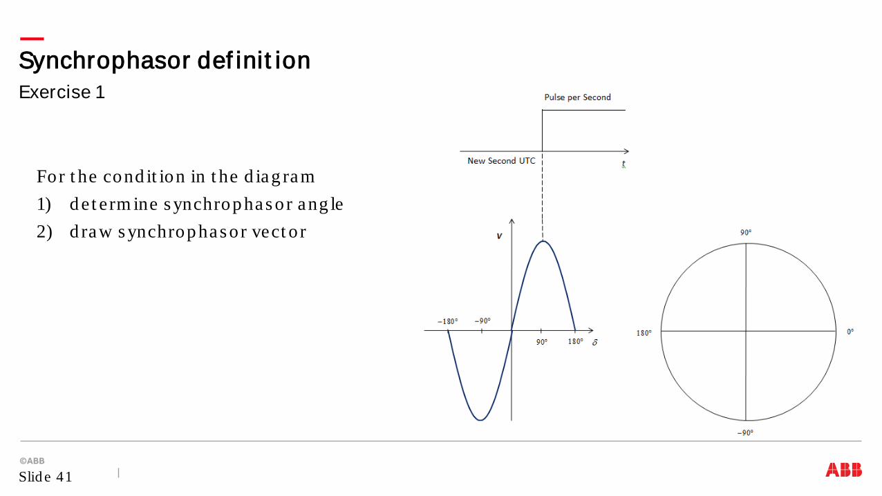
Exercise 1 Synchrophasor def init ion
Slid e 41
For t he cond it ion in t he d iag ram 1) d et erm ine s ynchrop has or ang le 2) d raw s ynchrop has or vect o r
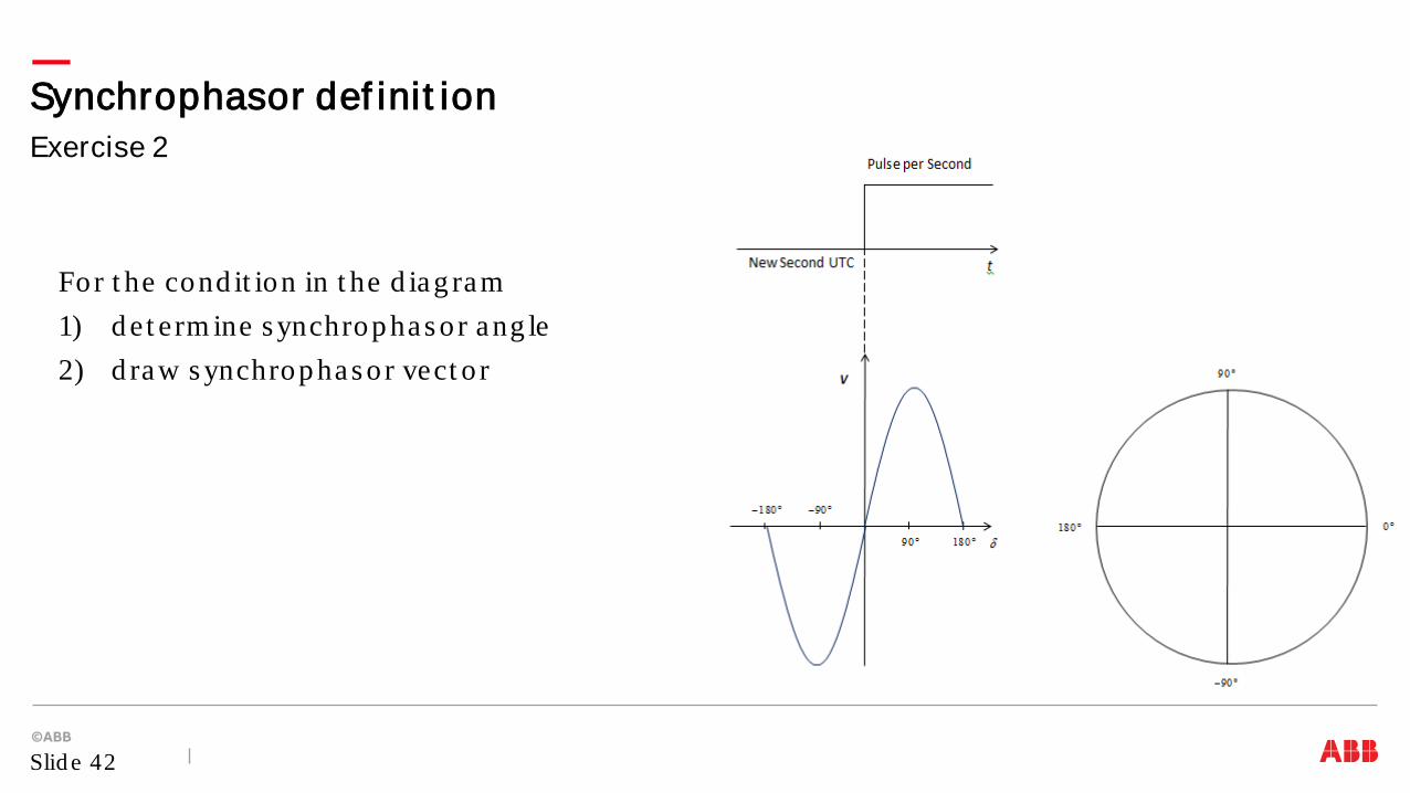
Exercise 2 Synchrophasor def init ion
Slid e 42
For t he cond it ion in t he d iag ram 1) d et erm ine s ynchrop has or ang le 2) d raw s ynchrop has or vect o r

Exercise 3 Synchrophasor def init ion
Slid e 43
For t he cond it ion in t he d iag ram 1) d et erm ine s ynchrop has or ang le 2) d raw s ynchrop has or vect o r
Exercise 4 Synchrophasor def init ion
Slid e 44
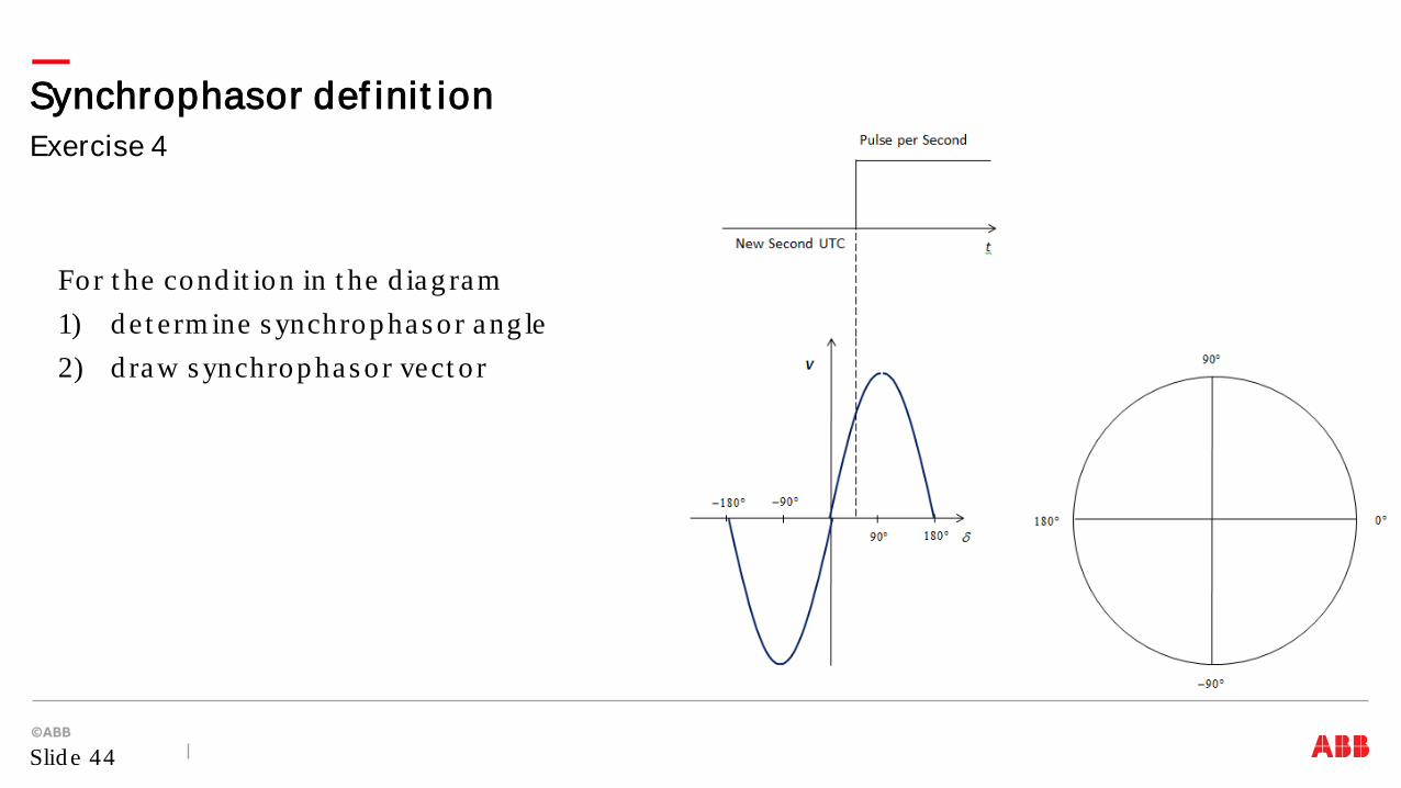
For t he cond it ion in t he d iag ram 1) d et erm ine s ynchrop has or ang le 2) d raw s ynchrop has or vect o r
Exercise 5 Synchrophasor def init ion
Slid e 45
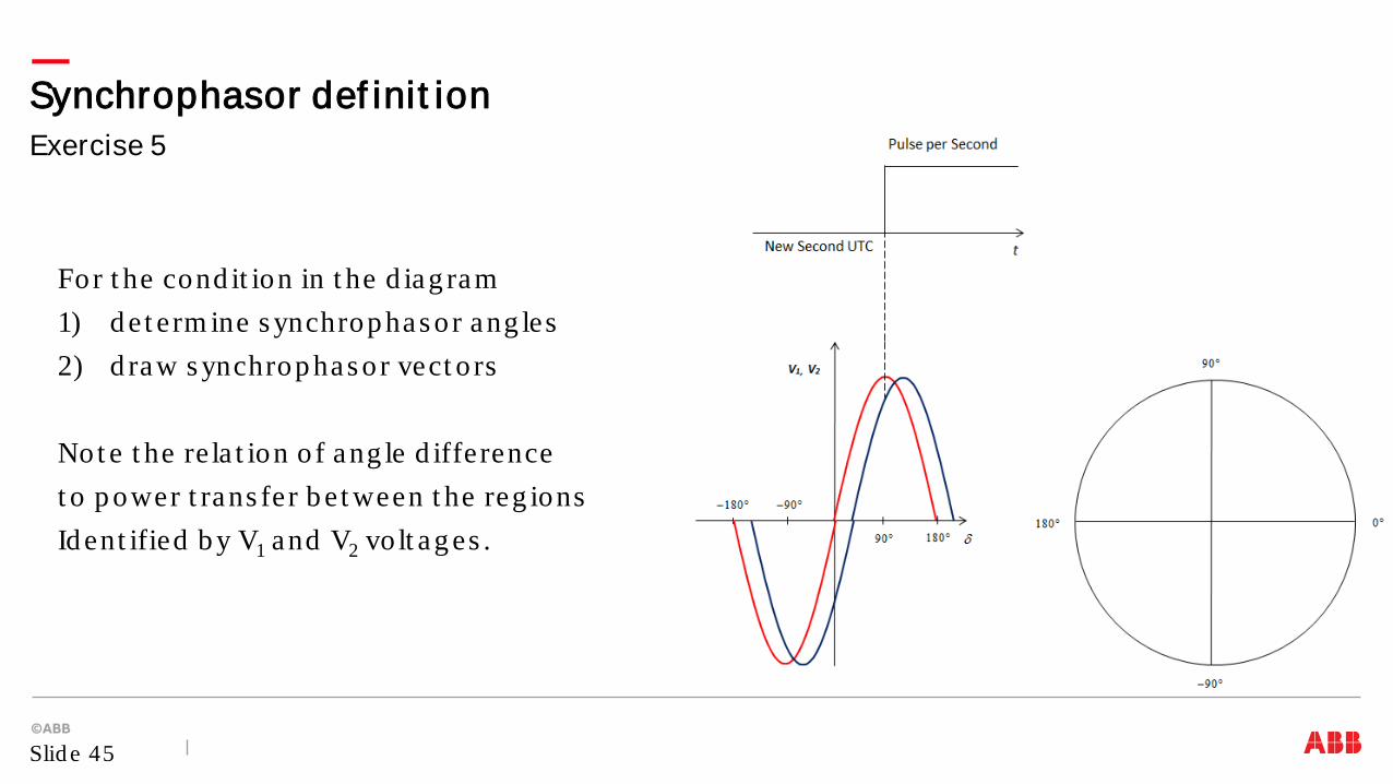
For t he cond it ion in t he d iag ram 1) d et erm ine s ynchrop has or ang les 2) d raw s ynchrop has or vect o rs Not e t he re la t ion o f ang le d ifference t o p ower t rans fer b e t ween t he reg ions Id ent ified b y V1 and V2 vo lt ag es .

Synchrophasor t echno log y us es p has ors o f current s and vo lt ag es t im es t am p ed t o UTC t im e Synchrop has or t echno log y b ring s m ore d e t a iled info rm a t ion ab out p ower s ys t em s , and is com p ared t o MRI in t he m ed ica l fie ld Synchrop has or t echno log y is d ep end ent on com m unica t ions and p recis e t im e s ynchroniza t ion The ab ilit y t o have s ynchronized p has ors from g eog rap hica lly d is p ers ed loca t ions in rea l t im e enab les b e t t e r cont ro l and p ro t ect ion o f p ower s ys t em s , lead ing t o hig her s ys t em s re liab ilit y
Conclusions
Slid e 46