handheld reconfi gurable rf transceiver - epiq solutions · pdf fileepiq solutions’...
TRANSCRIPT
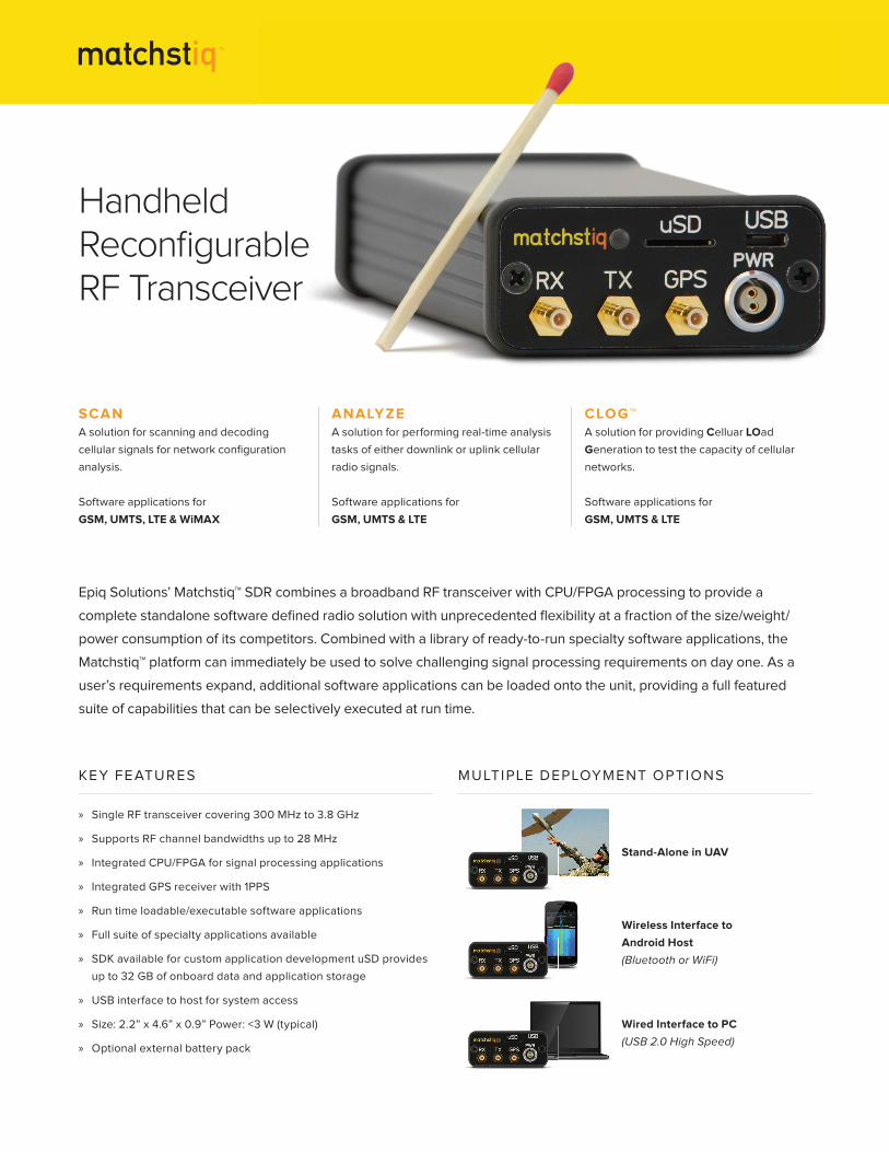
» Single RF transceiver covering 300 MHz to 3.8 GHz
» Supports RF channel bandwidths up to 28 MHz
» Integrated CPU/FPGA for signal processing applications
» Integrated GPS receiver with 1PPS
» Run time loadable/executable software applications
» Full suite of specialty applications available
» SDK available for custom application development uSD provides
up to 32 GB of onboard data and application storage
» USB interface to host for system access
» Size: 2.2” x 4.6” x 0.9” Power: <3 W (typical)
» Optional external battery pack
KEY FEATURES MULTIPLE DEPLOYMENT OPTIONS
Stand-Alone in UAV
Wireless Interface to
Android Host
(Bluetooth or WiFi)
Wired Interface to PC
(USB 2.0 High Speed)
Epiq Solutions’ Matchstiq™ SDR combines a broadband RF transceiver with CPU/FPGA processing to provide a
complete stand alone software defi ned radio solution with unprecedented fl exibility at a fraction of the size/weight/
power consumption of its competitors. Combined with a library of ready -to -run specialty software applications, the
Matchstiq™ platform can immediately be used to solve challenging signal processing requirements on day one. As a
user’s requirements expand, additional software applications can be loaded onto the unit, providing a full featured
suite of capabilities that can be selectively executed at run time.
HandheldReconfi gurableRF Transceiver
SCANA solution for scanning and decoding
cellular signals for network confi guration
analysis.
Software applications for
GSM, UMTS, LTE & WiMAX
ANALYZEA solution for performing real-time analysis
tasks of either downlink or uplink cellular
radio signals.
Software applications for
GSM, UMTS & LTE
CLOG™A solution for providing Celluar LOad
Generation to test the capacity of cellular
networks.
Software applications for
GSM, UMTS & LTE
165 Commerce Drive Suite 204
Schaumburg, IL 60173
(847) 598-0218
165 Commerce Drive Suite 204
Schaumburg, IL 60173
(847) 598-0218
http://www.epiqsolutions.com
http://www.epiqsolutions.com
RF OUTPUT . . . . . . . . . . . . . . . . . . . . . . . . . . . . . . . . . . . . . . . . . . . . . . . . . . . . SMB (50 Ω), SSMC option available
ARCHITECTURE . . . . . . . . . . . . . . . . . . . . . . . . . . . . . . . . . . . . . . . . . . . . . . . . Zero-IF (direct conversion)
TX TUNING RANGE . . . . . . . . . . . . . . . . . . . . . . . . . . . . . . . . . . . . . . . . . . . . . 300 MHz to 3800 MHz
TUNING STEP-SIZE . . . . . . . . . . . . . . . . . . . . . . . . . . . . . . . . . . . . . . . . . . . . . 1 kHz
TUNING TIME . . . . . . . . . . . . . . . . . . . . . . . . . . . . . . . . . . . . . . . . . . . . . . . . . . <2 mS
BASEBAND TRANSMIT GAIN CONTROL RANGE . . . . . . . . . . . . . . . . . . . 0 to 31 dB
BASEBAND CONFIGURABLE LOW-PASS FILTER . . . . . . . . . . . . . . . . . . . 0.75 MHz to 14 MHz
. . . . . . . . . . . . . . . . . . . . . . . . . . . . . . . . . . . . . . . . . . . . . . . . . . . . . . . . . . . . . . . (RF channel bandwidths from 1.5 MHz to 28 MHz)
RF TRANSMIT GAIN CONTROL RANGE . . . . . . . . . . . . . . . . . . . . . . . . . . . . 0 to 25 dB
MAX TX OUTPUT POWER . . . . . . . . . . . . . . . . . . . . . . . . . . . . . . . . . . . . . . . +10 dBm
D/A CONVERTER SAMPLE RATE . . . . . . . . . . . . . . . . . . . . . . . . . . . . . . . . . . Up to 40 MHz with 1 Hz resolution
D/A CONVERTER SAMPLE WIDTH . . . . . . . . . . . . . . . . . . . . . . . . . . . . . . . . 12 bits
POWER CONSUMPTION (STAND-ALONE) . . . . . . . . . . . . . . . . . . . . . . . . . 1.0 W (@ 0 dBm power output)
RF INPUT . . . . . . . . . . . . . . . . . . . . . . . . . . . . . . . . . . . . . . . . . . . . . . . . . . . . . . SMB (50 Ω), SSMC option available
ARCHITECTURE . . . . . . . . . . . . . . . . . . . . . . . . . . . . . . . . . . . . . . . . . . . . . . . . Zero-IF (direct conversion)
TUNING RANGE . . . . . . . . . . . . . . . . . . . . . . . . . . . . . . . . . . . . . . . . . . . . . . . . 300 MHz to 3800 MHz
TUNING STEP-SIZE . . . . . . . . . . . . . . . . . . . . . . . . . . . . . . . . . . . . . . . . . . . . . 1 kHz
TUNING TIME . . . . . . . . . . . . . . . . . . . . . . . . . . . . . . . . . . . . . . . . . . . . . . . . . . <2 mS
PRE-SELECT FILTER BANK . . . . . . . . . . . . . . . . . . . . . . . . . . . . . . . . . . . . . . . sub-octave from 300 MHz to 3800 MHz
TYPICAL NOISE FIGURE . . . . . . . . . . . . . . . . . . . . . . . . . . . . . . . . . . . . . . . . . 8 dB
TYPICAL IIP3 . . . . . . . . . . . . . . . . . . . . . . . . . . . . . . . . . . . . . . . . . . . . . . . . . . -10 dBm
RF GAIN CONTROL RANGE . . . . . . . . . . . . . . . . . . . . . . . . . . . . . . . . . . . . . . 0 to 58 dB
BASEBAND GAIN CONTROL RANGE . . . . . . . . . . . . . . . . . . . . . . . . . . . . . . 0 to 30 dB
BASEBAND CONFIGURABLE LOW-PASS FILTER . . . . . . . . . . . . . . . . . . . 0.75 MHz to 14 MHz
. . . . . . . . . . . . . . . . . . . . . . . . . . . . . . . . . . . . . . . . . . . . . . . . . . . . . . . . . . . . . . . (RF channel bandwidths from 1.5 MHz to 28 MHz)
TYPICAL I/Q BALANCE . . . . . . . . . . . . . . . . . . . . . . . . . . . . . . . . . . . . . . . . . . >50 dB
A/D CONVERTER SAMPLE RATE . . . . . . . . . . . . . . . . . . . . . . . . . . . . . . . . . Up to 40 MHz with 1 Hz resolution
A/D CONVERTER SAMPLE WIDTH . . . . . . . . . . . . . . . . . . . . . . . . . . . . . . . . 12 bits
POWER CONSUMPTION (STAND-ALONE) . . . . . . . . . . . . . . . . . . . . . . . . . 1.1 W
ESD PROTECTION AT RF INPUT . . . . . . . . . . . . . . . . . . . . . . . . . . . . . . . . . . 20 kV (human body model)
MAX SAFE RF LEVEL AT RF INPUT (AT MAX GAIN) . . . . . . . . . . . . . . . . . 20 dBm
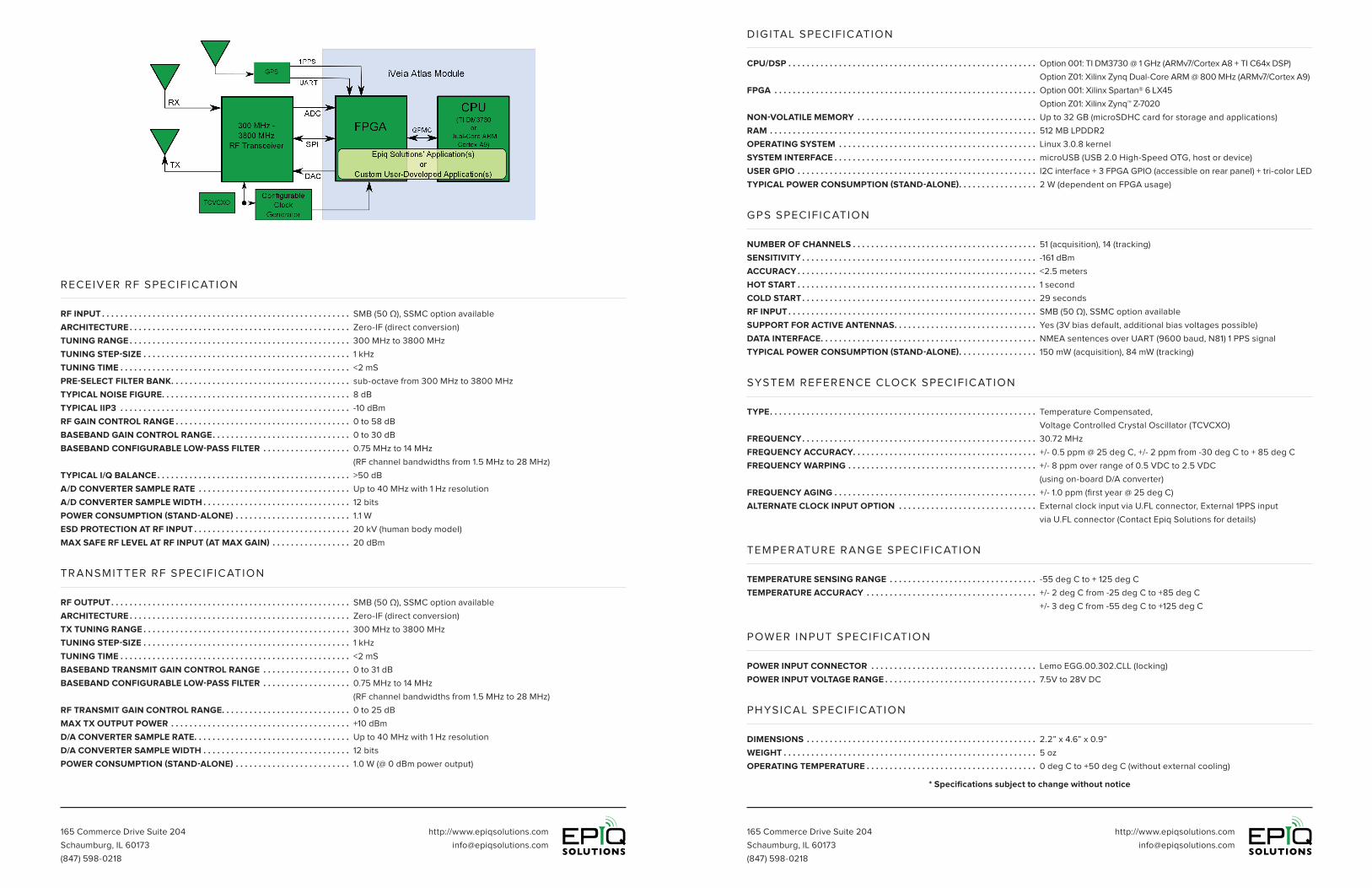
CPU/DSP . . . . . . . . . . . . . . . . . . . . . . . . . . . . . . . . . . . . . . . . . . . . . . . . . . . . . . Option 001: TI DM3730 @ 1 GHz (ARMv7/Cortex A8 + TI C64x DSP)
. . . . . . . . . . . . . . . . . . . . . . . . . . . . . . . . . . . . . . . . . . . . . . . . . . . . . . . . . . . . . . . Option Z01: Xilinx Zynq Dual-Core ARM @ 800 MHz (ARMv7/Cortex A9)
FPGA . . . . . . . . . . . . . . . . . . . . . . . . . . . . . . . . . . . . . . . . . . . . . . . . . . . . . . . . . Option 001: Xilinx Spartan® 6 LX45
. . . . . . . . . . . . . . . . . . . . . . . . . . . . . . . . . . . . . . . . . . . . . . . . . . . . . . . . . . . . . . . . . . .Option Z01: Xilinx Zynq™ Z-7020
NON-VOLATILE MEMORY . . . . . . . . . . . . . . . . . . . . . . . . . . . . . . . . . . . . . . . Up to 32 GB (microSDHC card for storage and applications)
RAM . . . . . . . . . . . . . . . . . . . . . . . . . . . . . . . . . . . . . . . . . . . . . . . . . . . . . . . . . . 512 MB LPDDR2
OPERATING SYSTEM . . . . . . . . . . . . . . . . . . . . . . . . . . . . . . . . . . . . . . . . . . . Linux 3.0.8 kernel
SYSTEM INTERFACE . . . . . . . . . . . . . . . . . . . . . . . . . . . . . . . . . . . . . . . . . . . . microUSB (USB 2.0 High-Speed OTG, host or device)
USER GPIO . . . . . . . . . . . . . . . . . . . . . . . . . . . . . . . . . . . . . . . . . . . . . . . . . . . . I2C interface + 3 FPGA GPIO (accessible on rear panel) + tri-color LED
TYPICAL POWER CONSUMPTION (STAND-ALONE) . . . . . . . . . . . . . . . . . 2 W (dependent on FPGA usage)
NUMBER OF CHANNELS . . . . . . . . . . . . . . . . . . . . . . . . . . . . . . . . . . . . . . . . 51 (acquisition), 14 (tracking)
SENSITIVITY . . . . . . . . . . . . . . . . . . . . . . . . . . . . . . . . . . . . . . . . . . . . . . . . . . . -161 dBm
ACCURACY . . . . . . . . . . . . . . . . . . . . . . . . . . . . . . . . . . . . . . . . . . . . . . . . . . . . <2.5 meters
HOT START . . . . . . . . . . . . . . . . . . . . . . . . . . . . . . . . . . . . . . . . . . . . . . . . . . . . 1 second
COLD START . . . . . . . . . . . . . . . . . . . . . . . . . . . . . . . . . . . . . . . . . . . . . . . . . . . 29 seconds
RF INPUT . . . . . . . . . . . . . . . . . . . . . . . . . . . . . . . . . . . . . . . . . . . . . . . . . . . . . . SMB (50 Ω), SSMC option available
SUPPORT FOR ACTIVE ANTENNAS . . . . . . . . . . . . . . . . . . . . . . . . . . . . . . . Yes (3V bias default, additional bias voltages possible)
DATA INTERFACE . . . . . . . . . . . . . . . . . . . . . . . . . . . . . . . . . . . . . . . . . . . . . . . NMEA sentences over UART (9600 baud, N81) 1 PPS signal
TYPICAL POWER CONSUMPTION (STAND-ALONE) . . . . . . . . . . . . . . . . . 150 mW (acquisition), 84 mW (tracking)
TYPE . . . . . . . . . . . . . . . . . . . . . . . . . . . . . . . . . . . . . . . . . . . . . . . . . . . . . . . . . . Temperature Compensated,
. . . . . . . . . . . . . . . . . . . . . . . . . . . . . . . . . . . . . . . . . . . . . . . . . . . . . . . . . . . . . . . Voltage Controlled Crystal Oscillator (TCVCXO)
FREQUENCY . . . . . . . . . . . . . . . . . . . . . . . . . . . . . . . . . . . . . . . . . . . . . . . . . . . 30.72 MHz
FREQUENCY ACCURACY . . . . . . . . . . . . . . . . . . . . . . . . . . . . . . . . . . . . . . . . +/- 0.5 ppm @ 25 deg C, +/- 2 ppm from -30 deg C to + 85 deg C
FREQUENCY WARPING . . . . . . . . . . . . . . . . . . . . . . . . . . . . . . . . . . . . . . . . . +/- 8 ppm over range of 0.5 VDC to 2.5 VDC
. . . . . . . . . . . . . . . . . . . . . . . . . . . . . . . . . . . . . . . . . . . . . . . . . . . . . . . . . . . . . . . (using on-board D/A converter)
FREQUENCY AGING . . . . . . . . . . . . . . . . . . . . . . . . . . . . . . . . . . . . . . . . . . . . +/- 1.0 ppm (first year @ 25 deg C)
ALTERNATE CLOCK INPUT OPTION . . . . . . . . . . . . . . . . . . . . . . . . . . . . . . External clock input via U.FL connector, External 1PPS input
. . . . . . . . . . . . . . . . . . . . . . . . . . . . . . . . . . . . . . . . . . . . . . . . . . . . . . . . . . . . . . . via U.FL connector (Contact Epiq Solutions for details)
POWER INPUT CONNECTOR . . . . . . . . . . . . . . . . . . . . . . . . . . . . . . . . . . . . Lemo EGG.00.302.CLL (locking)
POWER INPUT VOLTAGE RANGE . . . . . . . . . . . . . . . . . . . . . . . . . . . . . . . . . 7.5V to 28V DC
TEMPERATURE SENSING RANGE . . . . . . . . . . . . . . . . . . . . . . . . . . . . . . . . -55 deg C to + 125 deg C
TEMPERATURE ACCURACY . . . . . . . . . . . . . . . . . . . . . . . . . . . . . . . . . . . . . +/- 2 deg C from -25 deg C to +85 deg C
. . . . . . . . . . . . . . . . . . . . . . . . . . . . . . . . . . . . . . . . . . . . . . . . . . . . . . . . . . . . . . . +/- 3 deg C from -55 deg C to +125 deg C
DIMENSIONS . . . . . . . . . . . . . . . . . . . . . . . . . . . . . . . . . . . . . . . . . . . . . . . . . . 2.2” x 4.6” x 0.9”
WEIGHT . . . . . . . . . . . . . . . . . . . . . . . . . . . . . . . . . . . . . . . . . . . . . . . . . . . . . . . 5 oz
OPERATING TEMPERATURE . . . . . . . . . . . . . . . . . . . . . . . . . . . . . . . . . . . . . 0 deg C to +50 deg C (without external cooling)
RECEIVER RF SPECIFICATION
DIGITAL SPECIFICATION
GPS SPECIFICATION
SYSTEM REFERENCE CLOCK SPECIFICATION
POWER INPUT SPECIFICATION
TEMPER ATURE R ANGE SPECIFICATION
PHYSICAL SPECIFICATION
TR ANSMITTER RF SPECIFICATION
* Specifications subject to change without notice
165 Commerce Drive Suite 204
Schaumburg, IL 60173
(847) 598-0218
http://www.epiqsolutions.com
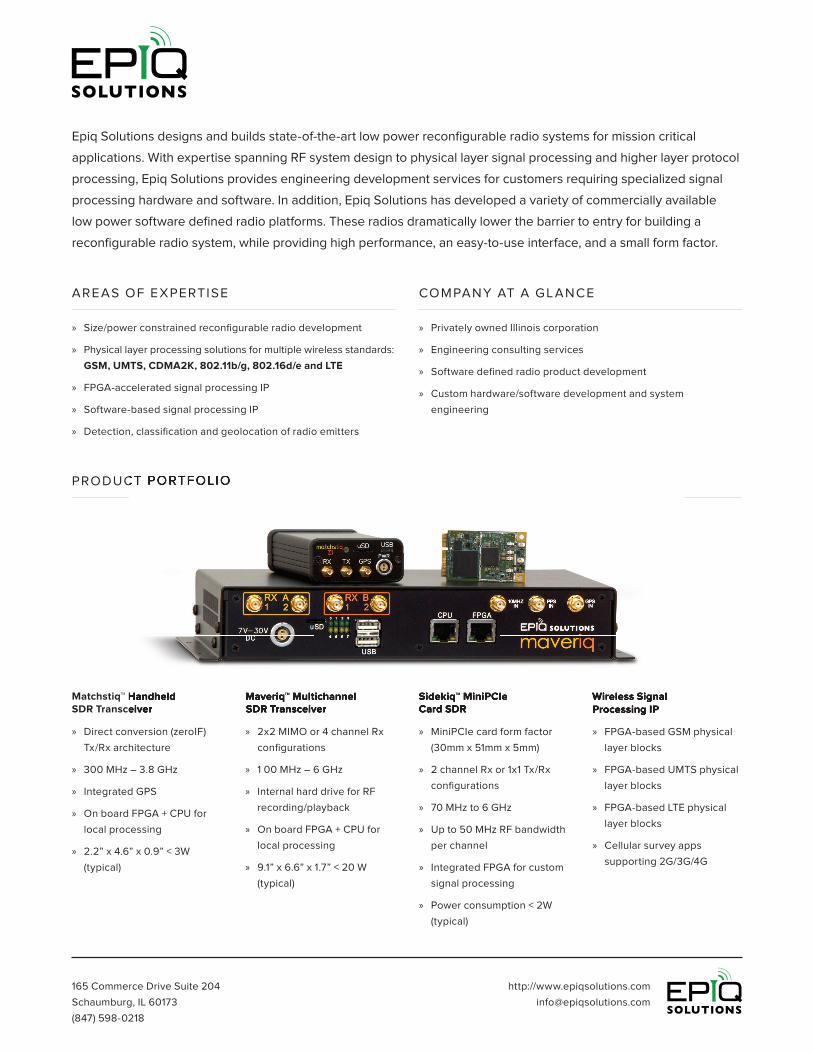
» 2x2 MIMO or 4 channel Rx
confi gurations
» 1 00 MHz – 6 GHz
» Internal hard drive for RF
recording/playback
» On board FPGA + CPU for
local processing
» 9.1” x 6.6” x 1.7” < 20 W
(typical)
Maveriq™ MultichannelSDR Transceiver
» Direct conversion (zero IF)
Tx/Rx architecture
» 300 MHz – 3.8 GHz
» Integrated GPS
» On board FPGA + CPU for
local processing
» 2.2” x 4.6” x 0.9” < 3W
(typical)
Epiq Solutions designs and builds state-of-the-art low power reconfi gurable radio systems for mission critical
applications. With expertise spanning RF system design to physical layer signal processing and higher layer protocol
processing, Epiq Solutions provides engineering development services for customers requiring specialized signal
processing hardware and software. In addition, Epiq Solutions has developed a variety of commercially available
low power software defi ned radio platforms. These radios dramatically lower the barrier to entry for building a
reconfi gurable radio system, while providing high performance, an easy-to-use interface, and a small form factor.
» Size/power constrained reconfi gurable radio development
» Physical layer processing solutions for multiple wireless standards:
GSM, UMTS, CDMA2K, 802 .11b/g, 802 .16d/e and LTE
» FPGA -accelerated signal processing IP
» Software -based signal processing IP
» Detection, classifi cation and geolocation of radio emitters
» Privately owned Illinois corporation
» Engineering consulting services
» Software defi ned radio product development
» Custom hardware/software development and system
engineering
» MiniPCIe card form factor
(30mm x 51mm x 5mm)
» 2 channel Rx or 1x1 Tx/Rx
confi gurations
» 70 MHz to 6 GHz
» Up to 50 MHz RF bandwidth
per channel
» Integrated FPGA for custom
signal processing
» Power consumption < 2W
(typical)
» FPGA- based GSM physical
layer blocks
» FPGA- based UMTS physical
layer blocks
» FPGA- based LTE physical
layer blocks
» Cellular survey apps
supporting 2G/3G/4G
PRODUCT PORTFOLIO
AREAS OF EXPERTISE COMPANY AT A GL ANCE
Matchstiq™ HandheldSDR Transceiver
Sidekiq™ MiniPCIeCard SDR
Wireless SignalProcessing IP
Maveriq™ MultichannelSDR Transceiver
PRODUCT PORTFOLIO
Matchstiq™ HandheldSDR Transceiver
Sidekiq™ MiniPCIeCard SDR
Wireless SignalProcessing IP