handbook on development & building works in railway ... · development & building works in...
TRANSCRIPT
January 2005 Edition
Handbook on
Development & Building Works in Railway Protection Zone All rights reserved. No part of this publication may be reproduced, stored in a retrieval system, or transmitted, in any form or by any means, electronic, mechanical, photocopying, recording or otherwise, without the prior permission of the Development and Building Control Department, Land Transport Authority.
Land Transport Authority Development & Building Control Department 251 North Bridge Road Singapore179102

CONTENTS

PREFACE
The Code of Practice for Railway Protection covers the submission procedures and requirements for obtaining approval for development and building proposals, permit to commence engineering works within the railway protection zone and railway corridor. Technical requirements for compliance at the design and construction stages of development are also stipulated.
This Handbook on Development & Building Works in Railway Protection Zone illustrates the interpretation of the technical requirements in the Code of Practice for Railway Protection and the safety considerations that would be required for carrying out any development and building works within the railway protection zone. Examples of design by architects and engineers that have adopted the ‘alternative solution’ approach are also illustrated and discussed.
As part of the Authority’s continual efforts to be more business friendly, the Authority embarked on the review of this Handbook in March 2004 and has completed this new edition. We welcome any suggestion or feedback from all users on the latest version of Handbook for improvement of future editions.
Development & Building Control Department Land Transport Authority Singapore

Guide to Users of Handbook
1. Introduction
Understanding and application of the Code of Practice for Railway Protection [herein referred to as the Code] may differ amongst users of the Code. Therefore, the aim of this handbook is to provide guidance to assist architects and professional engineers in their design of the development and building works within the railway protection zone.
This handbook contains explanatory commentary and supplemental material to guide the user through the technical requirements of Code. The commentary consists of the following components:
● Interpretation of requirements ● Application of requirements ● Illustrative figures ● Tables ● Case examples
2. Structure of handbook
This handbook has been structured in an easy to read manner as shown in the diagram below:
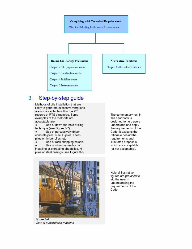
3. Step-by-step guide Methods of pile installation that are likely to generate excessive vibrations are not acceptable within the 2
nd
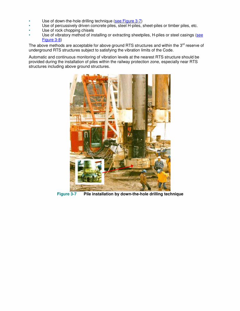
reserve of RTS structures. Some examples of the methods not acceptable are: ● Use of down-the-hole drilling technique (see Figure 3-7) ● Use of percussively driven concrete piles, steel H-piles, sheet-piles or timber piles, etc ● Use of rock chopping chisels ● Use of vibratory method of installing or extracting sheetpiles, H-piles or steel casings (see Figure 3-8)
The commentary text in this handbook is designed to help users understand and apply the requirements of the Code. It explains the rationale behind the requirements and illustrates proposals which are acceptable (or not acceptable).
Figure 3-6 View of a hydrofaise machine
Helpful illustrative figures are provided to aid the user in understanding the requirements of the Code.

Underground, Transition, Sub-aqueous & At Grade Structures
Above Ground Structures
Daily Twice weekly Daily Twice weekly Daily Nil
(Trice weekly -critical cases only)
Table 5-1 Typical instrumentation & frequency for construction activities within the railway protection zone
Tables that visually organize complex information for easy access are featured in this handbook.
Case examples This section discusses three examples of development sites within the railway protection zone that have adopted the ‘alternative solutions’ approach. They are:
• Design and construction of a retail podium above Novena Station
• Design and construction of an underground link from Bugis Junction to Bugis Station
• Deep excavation adjacent to and tunnelling below the existing RTS tunnels.
Actual case studies are given to show how the requirements of the Code can be satisfied. These case studies walk the user through potentially complicated scenarios.
4. Referencing of code and handbook
When making a reference to a particular provision, drawing or table in the Code, the following expressions are used:
I {in blue italic} Part 9 {in blue italic} Section 9.3 {in blue italic} Clause 9.3.3 {in blue italic} Clause 9.3.3.1 {in blue italic} Clause LTA/DBC/CPRP/008 {in blue italic} Drawing Table 9.1(a) {in blue italic} Table
When making a reference to a particular provision in this handbook, the following expressions are used:
3 {in black normal} Chapter 3.2 {in black normal} Section 3.2.1 {in black normal} Paragraph 3-2 {in black normal} Figure & Table
5. Glossary of acronyms
In this handbook, the following acronyms are used:
● BCU – Building Control Unit ● DBC – Development and Building Control Department ● NEL – North East Line ● LRT – Light Rail Transit ● LTA – Land Transport Authority ● MRT – Mass Rapid Transit ● PUB – Public Utilities Board ● QP – Qualified Person ● RTS – Rapid Transit System

6. Useful references ● Rapid Transit Systems (Development and Building Works in Railway Corridor and Railway
Protection Zone) Regulations ● Rapid Transit Systems (Railway Protection, Restricted Activities) Regulations ● Code of Practice for Railway Protection (Oct 2004 edition) ● Guide to Carrying Out Restricted Activities within Railway Protection and Safety Zones
Chapter 1 Meeting Performance Requirements
Quick preview
The primary consideration in railway protection is public’s safety. In this context, the Code has identified a set of objectives and the performance requirements. The objectives spell out the basic criteria that need to be satisfied to ensure safety of the rapid transit systems. To meet these objectives, performance requirements are spelt out. These provide quantifiable means for architects, engineers and contractors to work out suitable solutions using the appropriate assessment methods. This chapter provides further insight into the above objectives, performance requirements, solutions and assessment methods.
1.1 Framework for developing solutions
The framework for developing solutions for development and building works in the railway protection zone are formulated in the following hierarchy:
● Objectives ● Performance requirements ● Solutions ● Assessment methods
The objective guides the designer to interpret the Code’s requirements. Performance requirements outline the areas that need to be considered to achieve the objectives. All solutions must comply with the objectives and the performance requirements. Solutions developed to meet the deemed-to-satisfy provisions (as given in Part II Section 9 of the Code) will meet the performance requirements (as given in Part II Section 8 of the Code).
1.2 Objectives
The objectives (as given in Part II Section 8 of the Code) define broadly the goals to be fulfilled for the protection of the railway.
There are five basic objectives relating to:
● Structural safety ● Operational safety ● Fire safety ● Flood protection ● Inspection and maintenance
Architects, engineers, contractors, etc. must meet the above objectives in developing solutions from inception stage through planning, designing and constructing their development and building works; including associated works such as advance works and temporary works for the protection of the railway system.
1.3 Performance requirements
The performance requirements (as given in Part II Section 8 of the Code) define fundamental areas that need to be considered in working out solutions to meet the objectives.
The application of relevant performance requirements on development and building works within the railway protection zone are illustrated in Figures 1-2 and 1-3.
1.3.1 Structural safety
Development and building works could affect the integrity and durability of the RTS structures. Construction activities could also physically damage the RTS structures. The objectives are to ensure
that, in working out any solutions for carrying out these works, they do not create a situation that would damage or affect the integrity of the RTS structures.
It is important for the QP and/or the appointed expert(s) to fully understand the design of the RTS structures, their present condition and the effects of the development and building works on the RTS structures due to the proposal.
1.3.2 Operational safety
In order for trains to operate safely, the rapid transit system tunnel and track alignment must not be subjected to excessive deformation and changes. If the design limits are exceeded, there will be a possibility that the train would not be able to travel at the optimum speed, the comfort of passengers may be affected or in the worst scenario cause train to derail.
1.3.3 Fire safety
The rapid transit systems are designed and constructed so that in the event of a fire the safety of people is not compromised. During development and building works, especially where works may affect the means of escape from the station, adequate fire safety measures and protection systems must be provided.
1.3.4 Flood protection
The rapid transit systems are designed to meet flood threshold levels as approved by the Drainage Department of the PUB. Any underground links to the RTS structures, services connections, etc. during construction or permanent stage must not subject the rapid transit systems to any risk of flooding.
1.3.5 Inspection and maintenance
Development and building works around, above and in the vicinity of the rapid transit systems must not cause obstruction or inaccessibility for the inspection and maintenance of the rapid transit systems.
1.4 Solutions
In order for designers to provide innovative and creative solutions which are practical and technically sound, the Code allows the architects, engineers, contractors, etc. to choose any of the processes below in developing a solution:
● Complying with the deemed-to-satisfy provisions as given in Part II Section 9 of the Code; or ● Formulating an alternative solution which meets the performance requirements (as given in
Part II Section 8 of the Code) or is shown to be at least equivalent to the deemed-to-satisfy provision; or
● a combination of above

Figure 1-2 Performance provisions applicable to development and building located
adjacent to above ground RTS station and viaduct
Figure 1-3 Performance provisions applicable to development and building linked to an
underground RTS station
The term ‘deemed to satisfy provision’ means exactly what it implies: if a design complies with all the relevant deemed to satisfy provisions, then the design is deemed to satisfy the corresponding performance requirements, and is therefore eligible to be approved.
An alternative solution is a design that can be shown to comply with the relevant performance requirements.
1.5 Assessment methods
In developing solutions either to meet the deemed-to-satisfy provisions or alternative solutions, it is necessary to adopt a suitable methodology to assess whether they comply with the performance requirements.
When adopting an alternative solution, it is imperative that proper assessment methods must be adopted to predict the effects of the proposed development and building works on the RTS.
The assessment of a proposed alternative solution can be undertaken by one of the following assessment methods or a combination of methods below:
● Acceptable documentary evidence ● Verification methods ● Comparison with deemed-to-satisfy provisions ● Expert judgement
1.5.1 Documentary evidence
This assessment method shall be supported with documentary evidence that clearly shows that a similar solution had been proven to be suitable and successful in meeting the objectives in similar circumstances.
1.5.2 Verification methods
In developing solutions to meet the performance requirements, either to show that they meet the deemed-to-satisfy provisions or alternative solutions, it is crucial that the methods used to model or simulate the actual conditions are suitable for use in similar situations. Sensitivity studies would be needed where necessary to check that the parameters used are reasonable.
Besides these, a system to monitor and check that the results of the evaluation during construction shall also be worked out. Necessary mechanisms must be in place to determine whether any re-evaluation or review needs to be considered during the implementation of the alternative solutions so that actions can be taken and decisions could be made if the situation develops differently from forecast and before a dangerous condition arises. This would therefore include a hazard analysis and measures to mitigate those risks identified.
1.5.3 Expert judgement
Alternative solutions must be prepared by an expert(s) who has the necessary experience, skills and knowledge in the relevant field. The basis to demonstrate whether the solution complies with the performance requirements thus fulfilling the objectives of railway protection should be clearly spelt out and substantiated in the assessment.
1.5.4 Comparison with deemed-to-satisfy provisions
Alternative solution is deemed to satisfy performance requirement if it is demonstrated to be equivalent to the deemed-to-satisfy provisions by comparison.
Chapter 2 Site Preparation Works
Quick preview
In this chapter, we present the salient safety considerations for carrying out mobilisation and demolition works in the railway protection zone. Acceptable practice of demarcating RTS reserve lines on site, method of carrying out mobilisation works, demolition works, etc. are explained with photographs taken from development sites. These good practices should be considered to ensure the safety of the railway.
2.1 Mobilisation works
Mobilisation works within the railway protection zone must satisfy the requirements of Part II Clauses 9.2.1 and 9.2.2 of the Code as described below.
Safety considerations relating to carrying out any restricted activity in the railway protection zone are available in the Guide to Carrying out Restricted Activities within Railway Protection and Safety Zone.
2.1.1 Demarcation of reserve lines
All railway reserve lines must be pegged and demarcated clearly on site by a registered land surveyor based on an approved certified survey plan. These reserve lines must be maintained throughout the entire duration of works. The purpose of demarcating the reserve lines on site is to enhance the recognition of the various reserves by QPs, contractors, sub-contractors, resident engineers, clerk-of-works, crane operators, etc.
2.1.1.1 Above ground RTS Structures
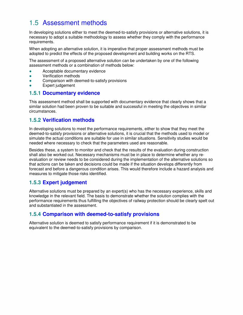
For demarcating the 1st reserve line on site, the details given in Figure 2-1 must be adopted. An example of such a provision is shown in Figure 2-2. No demarcation markers should be erected higher than the viaduct beam level as they may fall onto the viaduct in the event of any collapse.
Figure 2-1 Demarcation details for first reserve line of above ground RTS

Figure 2-2 Provision of first reserve line demarcation on site
2.1.1.2 Underground RTS structures
Before work commences, the exact location of the RTS structures and the 1st reserve line must be established. This is to ensure the following:
• Drilling work is done as approved and there will be no possibility of drilling into the underground RTS structure.
• Load bearing piles falling within the zone of influence are debonded or alternatively checked so as to prevent imposing additional load on the tunnel lining.
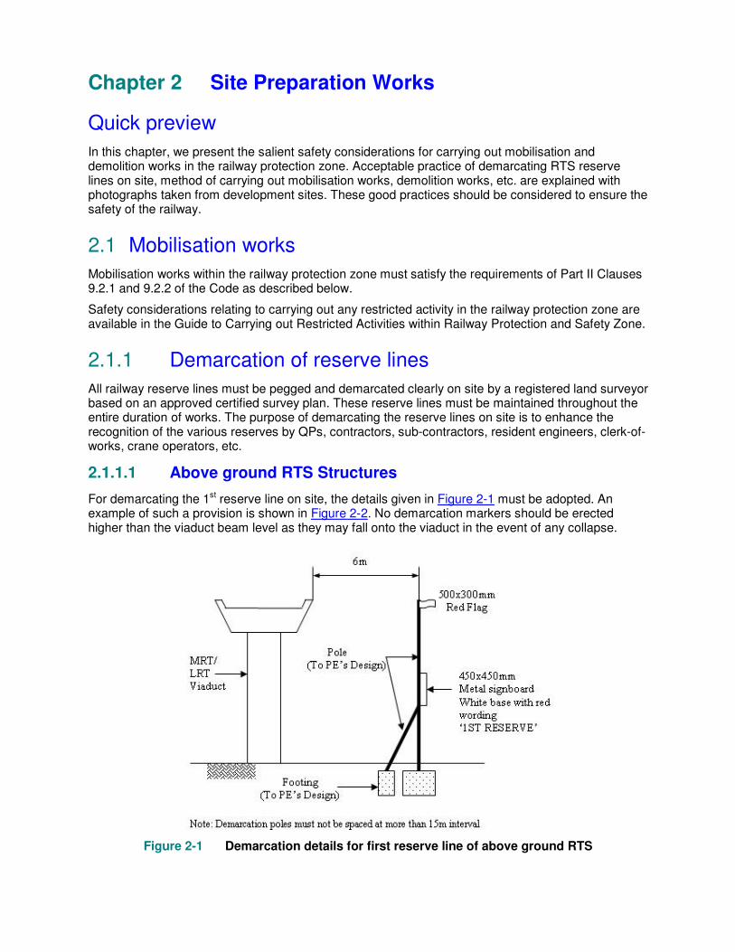
The 1st, 2nd and 3rd reserves (see Figure 2-3) of an underground RTS structure must be displayed on site at all times during the construction period.
Figure 2-3 Details of MRT reserve markers
Figure 2-4 Prominent display of MRT third reserve on site
2.1.2 Storage of materials
Site activities involving any storage or placement of construction materials, temporary storage of flammable fluid, gas cylinders, etc. are not allowed within the 1st reserve of any RTS structure (see Figure 2-5).
The main safety concerns relating to the storage or placement of materials near the RTS structures are as follows:
• Fire hazard to the above ground RTS structures. • Combustible material on fire may cause smoke and fumes to enter the underground station
(through vent shaft or station entrance). • Additional stress onto the underground RTS structures should not exceed the allowable limits
in the Code.
Safety considerations relating to the storage and placement of materials within the railway protection and safety zones are available in the Guide to Carrying Out Restricted Activities within Railway Protection and Safety Zones.
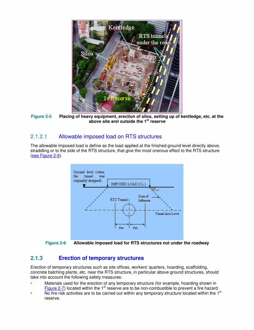
Figure 2-5 Placing of heavy equipment, erection of silos, setting up of kentledge, etc. at the
above site arel outside the 1st reserve
2.1.2.1 Allowable imposed load on RTS structures
The allowable imposed load is define as the load applied at the finished ground level directly above, straddling or to the side of the RTS structure, that give the most onerous effect to the RTS structure (see Figure 2-6).
Figure 2-6 Allowable imposed load for RTS structures not under the roadway
2.1.3 Erection of temporary structures
Erection of temporary structures such as site offices, workers' quarters, hoarding, scaffolding, concrete batching plants, etc. near the RTS structure, in particular above ground structures, should take into account the following safety measures:
• Materials used for the erection of any temporary structure (for example, hoarding shown in Figure 2-7) located within the 1st reserve are to be non-combustible to prevent a fire hazard.
• No fire risk activities are to be carried out within any temporary structure located within the 1st reserve.

• Scaffolding is to be designed such that it is stable, robust and suitably tied back to prevent any collapse onto the above ground RTS structure.
• Nets or other suitable screens are provided to prevent any debris, tools, etc. from falling onto the tracks.
If temporary structures such as hoarding, passageway, etc. have to be erected next to/ within RTS station and its entrances, conditions in Part II Clause 9.4.5 of the Code must be satisfied. The following measures must be considered:
• Provide fire compartment to work area. • Maintain clear minimum width for fire escape in station. • Ensure safe and protected passageway access in and out of RTS station. • The structures must not interfere with the free flow of air into and out of the RTS ventilation
shafts. • Provide sufficient ventilation facilities in passageway. • Must not affect the existing fire safety and fire protection system. • Provide adequate directional signages and lightings to passageway.
Figure 2-7 Non-combustible hoarding located below and within 6m from the edge of
viaduct is constructed using non-combustible material
Figures 2-8 and 2-9 show some examples of temporary structures erected within the station that provide fire compartment to work site, ventilation facilities, proper lightings , signages, etc. for passagers safe use.

Figure 2-8 A 2 hours fire rated hoarding for works site within station
Figure 2-9 A safe and protected temporary passageway is provided during the construction
of a commercial development
2.1.4 Access under viaduct
Construction equipment or vehicles could be higher than the vertical clearance below the viaduct. To prevent such vehicles from hitting the viaduct beam, all accesses under the viaduct must be provided with temporary height restriction gantries on both sides of the viaduct (see Figure 2-10).
Such gantries are to be adequately designed by a Professional Engineer (Civil). Reflective paint is to be provided on the steel structure to enhance visibility. Full drawing details of a temporary height restriction gantry can be found in the Guide to Carrying Out Restricted Activities within Railway Protection & Safety Zones.
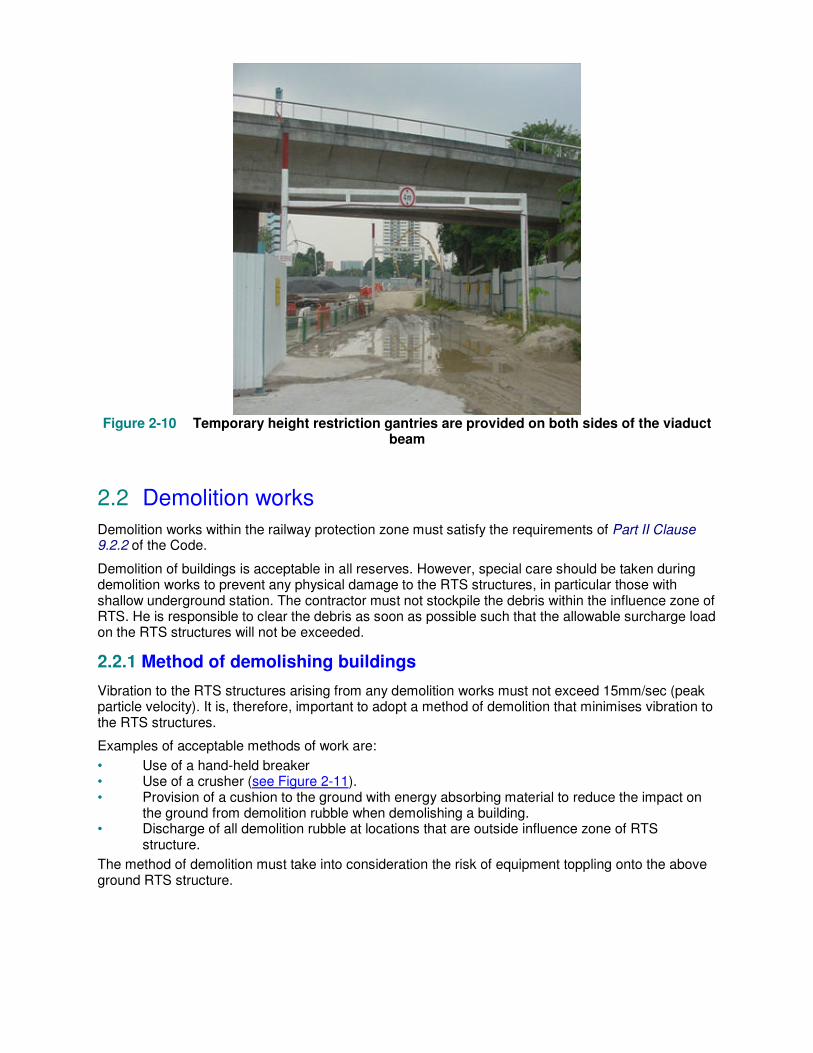
Figure 2-10 Temporary height restriction gantries are provided on both sides of the viaduct
beam
2.2 Demolition works
Demolition works within the railway protection zone must satisfy the requirements of Part II Clause 9.2.2 of the Code.
Demolition of buildings is acceptable in all reserves. However, special care should be taken during demolition works to prevent any physical damage to the RTS structures, in particular those with shallow underground station. The contractor must not stockpile the debris within the influence zone of RTS. He is responsible to clear the debris as soon as possible such that the allowable surcharge load on the RTS structures will not be exceeded.
2.2.1 Method of demolishing buildings
Vibration to the RTS structures arising from any demolition works must not exceed 15mm/sec (peak particle velocity). It is, therefore, important to adopt a method of demolition that minimises vibration to the RTS structures.
Examples of acceptable methods of work are:
• Use of a hand-held breaker • Use of a crusher (see Figure 2-11). • Provision of a cushion to the ground with energy absorbing material to reduce the impact on
the ground from demolition rubble when demolishing a building. • Discharge of all demolition rubble at locations that are outside influence zone of RTS
structure.
The method of demolition must take into consideration the risk of equipment toppling onto the above ground RTS structure.

Figure 2-11 Use of a crusher for demolition helps to minimise the impact of vibration
2.2.2 Method of demolishing station structures
Removal of parts of the RTS structures such as the station walls, columns, beams, etc. is sometime necessary as part of the construction of linkages to the station. In this aspect, the safety considerations would include the following items:
• Minimise the vibration induced on the station structure (not exceeding 15mm/sec peak particle velocity).
• Minimise the generation of dust and noise disturbance or inconvenience to the commuters during train operation hours.
• Maintain the flood protection level of the stations (for more details on flood protection of stations, please refer to Chapter 4)
Examples of acceptable demolition methods include:
• Stitch coring (see Figure 2-12) • Use of a diamond cutter (see Figure 2-13) or diamond wire saw (see Figure 2-14)
Use of a hydro-jet (subject to measures to ensure no flooding will occur) (see Figure 2-15)
Figure 2-12 Stitch coring method for cutting wall panels helps to minimise vibration and
noise levels
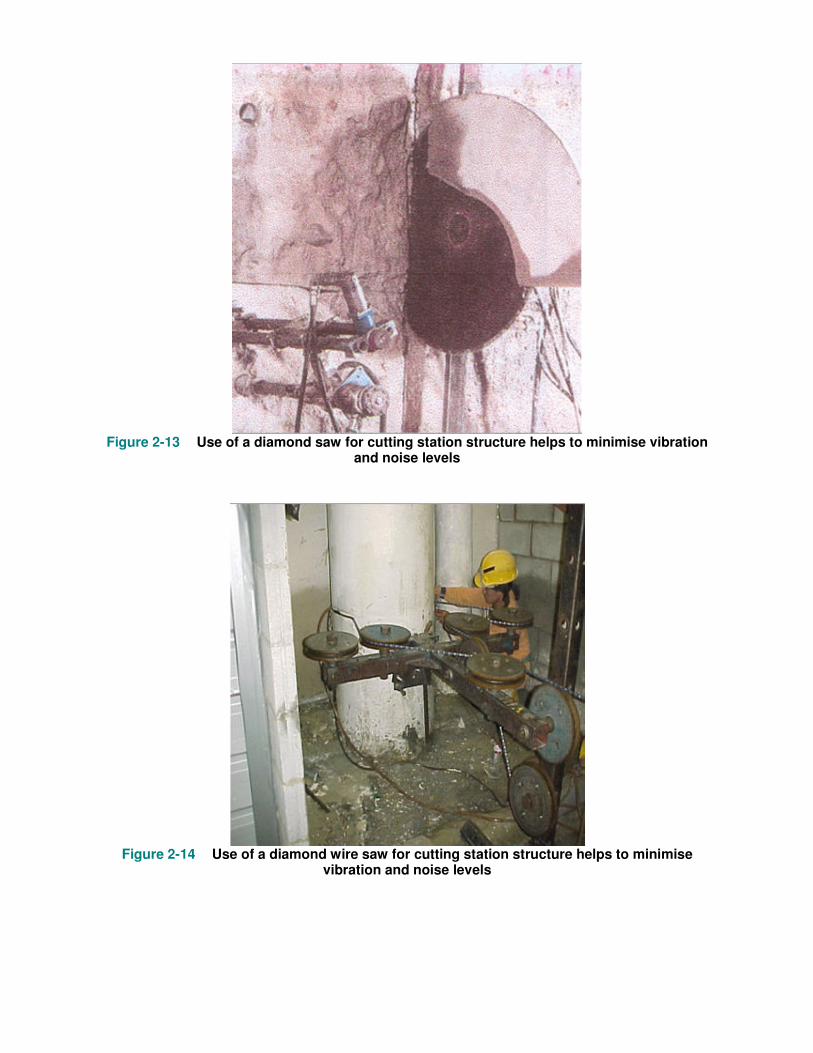
Figure 2-13 Use of a diamond saw for cutting station structure helps to minimise vibration
and noise levels
Figure 2-14 Use of a diamond wire saw for cutting station structure helps to minimise
vibration and noise levels

Figure 2-15 Use of a hydro-jet for demolition helps to minimise dust, fire hazard, vibration
and noise levels
2.2.3 Monitoring of vibration levels
During the period of demolition, vibration levels on the nearby RTS structure are to be closely monitored. This can be done by installing vibration sensors on the RTS structure (refer to Figures 5-17 and 5-18) to provide a continuous monitoring of the vibration levels induced by the demolition works. More information relating to vibration monitoring is available in Chapter 5.
Chapter 3 Substructure Works
Quick preview
This chapter discusses the considerations for carrying out excavation and construction of substructure works in the railway protection zone. Requirements relating to the set back of these substructures from the RTS structures, acceptable method of construction in the railway protection zone, etc. are illustrated with sketches and photographs.
3.1 Footing and raft
The design and construction of footings or rafts within the railway protection zone must satisfy the requirements of the Code.
For footings and rafts within the 1st reserve, the following requirements must be complied with:
• Additional load on the underground RTS structure must not exceed the allowable limit in the Code.
• Works must not affect the integrity of waterproofing system of the underground RTS structures.
• Works must not affect the viaduct drainage and lightning protection system.
If RTS facilities are affected, it must be suitably diverted, repaired and reinstated to the Authority’s satisfaction.
If the RTS facilities fall within the development boundary, access must be given for the railway operator to carry out maintenance.
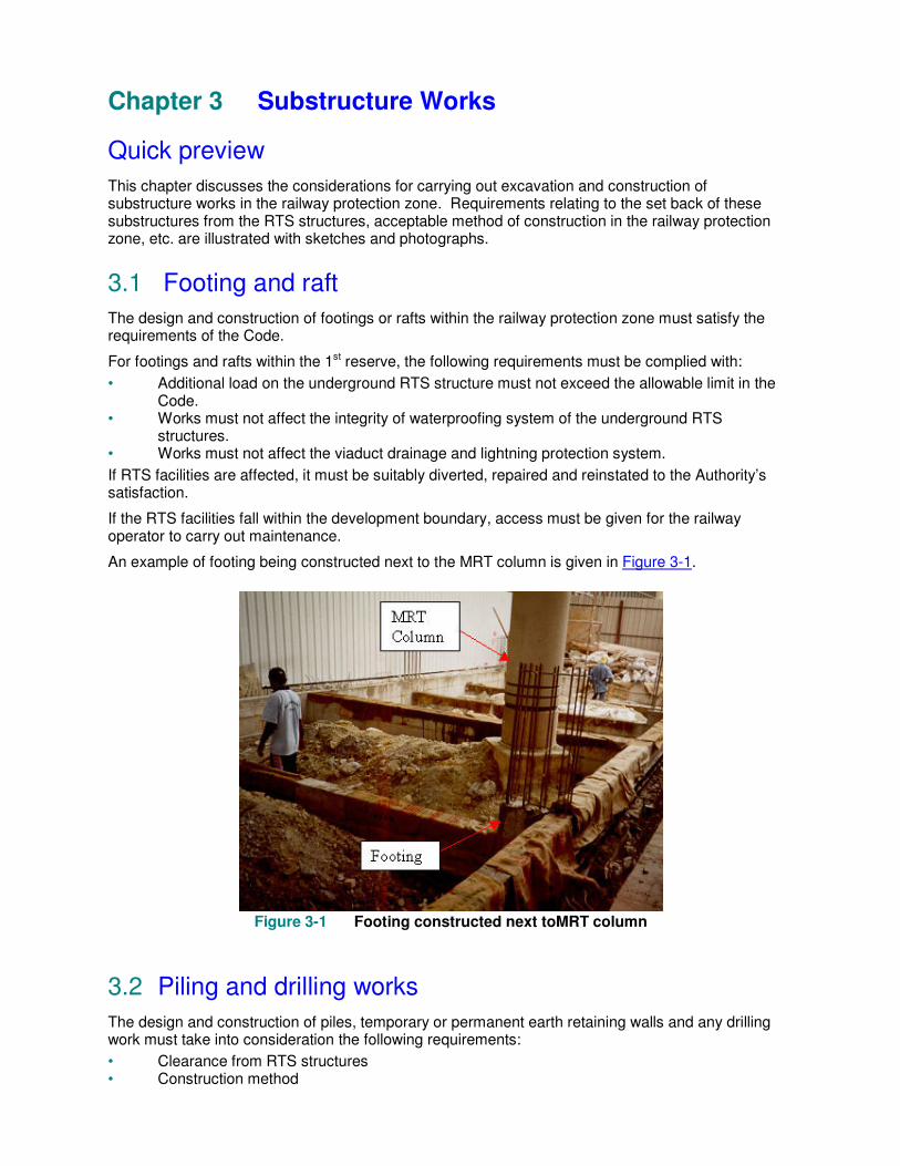
An example of footing being constructed next to the MRT column is given in Figure 3-1.
Figure 3-1 Footing constructed next toMRT column
3.2 Piling and drilling works
The design and construction of piles, temporary or permanent earth retaining walls and any drilling work must take into consideration the following requirements:
• Clearance from RTS structures • Construction method

• Allowable load transfer
3.2.1 Clearance from RTS
Piling works are generally not allowed within the 1st reserve of all types of RTS structures. However, on a case-by-case basis, the following may be allowed :
• Piles that are located less than 6m but more than 3m horizontally from the extreme edge of an underground RTS structure (see Figure 3-2).
• Toes of raker piles must be at least 3m from the edge of the RTS structures. • Limited bakau piling terminating at least 3m above the crown of tunnels or underground RTS
structures (see Figure 3-2). • Diaphragm walls within or near the 1st reserve must have installation panel width of not more
than 3m.
Where piles or retaining structures are proposed to be located less than 6m but more than 3m horizontally from the extreme edge of an underground RTS structure, the following must be considered :
• The bored hole or trenches must be fully supported at all time to prevent soil collapse. • Piles must not be installed by percussive or displacement method. • Positions of piles are to be pegged on site by a registered surveyor based on the approved
certified survey plan. • Frequent checks on pile vertical alignment must be carried out during installation.
Where bakau piles terminating at least 3m above the crown of tunnels or underground RTS structure are proposed, some examples of safety measures to be provided are:-
• Close supervision by competent person. • Install piles in pre-determined lengths to control penetration.
Figure 3-2 Above pile configuration may be considered on case-by-case basis
Where piles are to be installed near viaduct piers supported on raker piles, they must be kept at least 3m clear from the toes of the viaduct raker piles on plan.
3.2.2 Construction method
Pile installation must not cause ground movement, displacement or vibration at the RTS structures, exceeding the Code limits.
The stability of the bored holes within the railway protection zone of an underground RTS structure should always be assured by suitable methods such as the use of casing or drilling mud (stability checks are required) to prevent collapse of bored holes, as appropriate.
Some examples of pile installation methods within the railway protection zone that minimise the effect of vibration at the underground, transition or sub-aqueous RTS structures are:
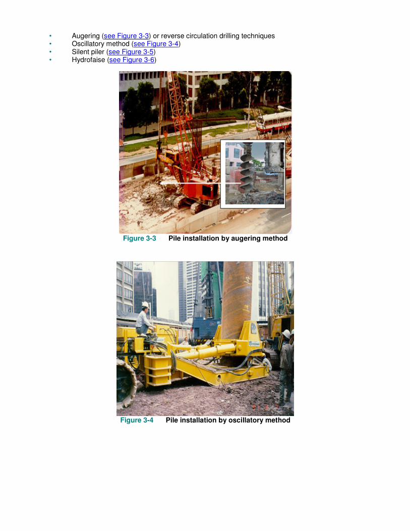
• Augering (see Figure 3-3) or reverse circulation drilling techniques • Oscillatory method (see Figure 3-4) • Silent piler (see Figure 3-5) • Hydrofaise (see Figure 3-6)
Figure 3-3 Pile installation by augering method
Figure 3-4 Pile installation by oscillatory method

Figure 3-5 Sheetpile installation by a silent piler
Figure 3-6 View of a hydrofaise machine
Methods of pile installation that are likely to generate excessive vibrations are not acceptable within the 2nd reserve of RTS structures. Some examples of the methods not acceptable are:
• Use of down-the-hole drilling technique (see Figure 3-7) • Use of percussively driven concrete piles, steel H-piles, sheet-piles or timber piles, etc. • Use of rock chopping chisels • Use of vibratory method of installing or extracting sheetpiles, H-piles or steel casings (see
Figure 3-8)
The above methods are acceptable for above ground RTS structures and within the 3rd reserve of underground RTS structures subject to satisfying the vibration limits of the Code.
Automatic and continuous monitoring of vibration levels at the nearest RTS structure should be provided during the installation of piles within the railway protection zone, especially near RTS structures including above ground structures.
Figure 3-7 Pile installation by down-the-hole drilling technique
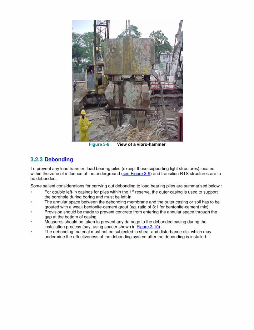
Figure 3-8 View of a vibro-hammer
3.2.3 Debonding
To prevent any load transfer, load bearing piles (except those supporting light structures) located within the zone of influence of the underground (see Figure 3-9) and transition RTS structures are to be debonded.
Some salient considerations for carrying out debonding to load bearing piles are summarised below :
• For double left-in casings for piles within the 1st reserve, the outer casing is used to support the borehole during boring and must be left-in.
• The annular space between the debonding membrane and the outer casing or soil has to be grouted with a weak bentonite-cement grout (eg. ratio of 3:1 for bentonite-cement mix).
• Provision should be made to prevent concrete from entering the annular space through the gap at the bottom of casing.
• Measures should be taken to prevent any damage to the debonded casing during the installation process (say, using spacer shown in Figure 3-10).
• The debonding material must not be subjected to shear and disturbance etc. which may undermine the effectiveness of the debonding system after the debonding is installed.
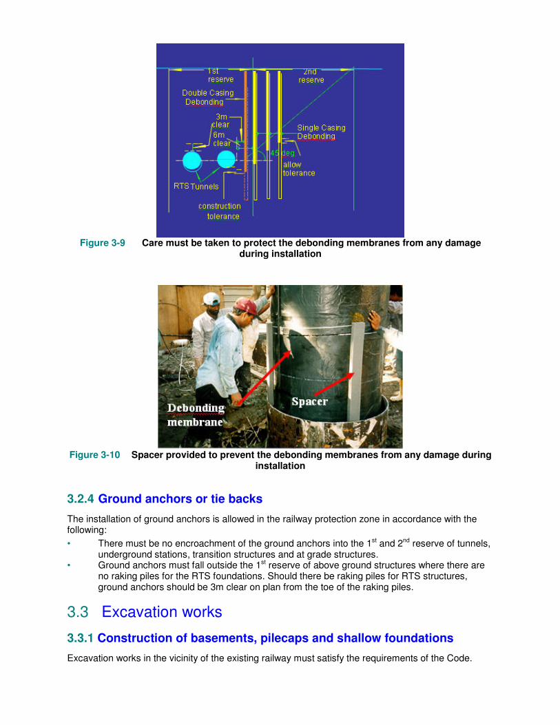
Figure 3-9 Care must be taken to protect the debonding membranes from any damage
during installation
Figure 3-10 Spacer provided to prevent the debonding membranes from any damage during
installation
3.2.4 Ground anchors or tie backs
The installation of ground anchors is allowed in the railway protection zone in accordance with the following:
• There must be no encroachment of the ground anchors into the 1st and 2nd reserve of tunnels, underground stations, transition structures and at grade structures.
• Ground anchors must fall outside the 1st reserve of above ground structures where there are no raking piles for the RTS foundations. Should there be raking piles for RTS structures, ground anchors should be 3m clear on plan from the toe of the raking piles.
3.3 Excavation works
3.3.1 Construction of basements, pilecaps and shallow foundations
Excavation works in the vicinity of the existing railway must satisfy the requirements of the Code.

3.3.1.1 Design of Temporary Works
The retaining system adopted should minimise impact on the RTS structures. The design of temporary works for excavation should be in accordance with acceptable codes of practice.
• The load factors adopted should comply with the acceptable code with no reduction allowed. • The design strength of material should not exceed that stipulated in the acceptable code or
manufacturer’s recommendations. • There should be adequate factor of safety for stability of retaining system. • For strutting system, the struts should be effectively restrained in both major and minor axes;
king posts should abut the struts to effectively restraint the struts in the major axis. Walers should be continuous for effective load distribution.
• Jet grouting must comply with the requirements of BS EN 12716. • Ground movements, movements of the RTS structures and ground water draw-down at
various stages of excavations should be assessed and tabulated for monitoring. The allowable limits in the Code should not be exceeded, otherwise an alternative solution should be adopted.
• The allowable limits for the monitoring instrumentation should not exceed the design values.
3.3.1.2 Excavation Works
Excavation for the construction of basements or pile caps would result in the relief of stresses in ground leading to settlement/ heave and lateral movement of the ground. Loss of ground water to the excavation area also causes lowering of the ground water level and pore water (piezometric) pressure leading to consolidation settlement.
These factors may have detrimental effects on the RTS structures particularly tunnels in marine clay, foundation of viaducts and stations, non-suspended apron slabs and utilities serving the rapid transit systems such as sewer lines. Measures to minimise ground movement and reduction in the pore water pressure must be implemented during excavation work.
The design and construction of earth retaining systems should pay special attention to the following :
• Retaining walls should be sufficiently rigid and adequately strutted and braced to minimise lateral ground movement (see Figure 3-11).
• Lateral supports to earth retaining walls should be installed immediately after each stage of excavation.
• Excavation should be carried out in a compartmentalised manner to minimise the ground movement (see Figure 3-12) where appropriate.
• Earth retaining walls should be sufficiently watertight to prevent ground water draw-down and gaps between individual pile of temporary earth retaining walls should be sealed. For example, grout piles can be used to seal up the gaps in the temporary earth retaining wall (see Figure 3-13).
• Toe of earth retaining walls should be deep enough to cut-off the seepage of water and stability of retaining wall should be checked.
• Basement walls and slabs should be watertight and designed for full hydrostatic pressures with no pressure relief.
• The bottom of an excavation should be provided with blinding concrete immediately after reaching the formation to minimise lowering of ground water.
Where lowering of the groundwater table is anticipated to occur even with the provision of a cut off wall, additional measures to minimise groundwater lowering should be provided before commencement of excavation works. Such measures include the use of recharging wells, designed, installed and tested before work starts. QP should design these wells sufficiently large with area well covered to ensure their effectiveness in maintaining the groundwater table.
Potential changes to the resistance against flotation of the station and tunnels due to excavation works both in the temporary and permanent states must be checked and measures implemented to prevent any uplift affecting stability of the RTS structures.

Figure 3-11 Struts and bracing help to minimise ground movement due to excavation
Figure 3-12 Carrying out excavation in small compartments helps to minimise ground
movement
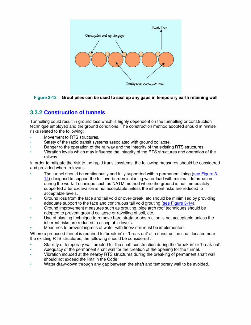
Figure 3-13 Grout piles can be used to seal up any gaps in temporary earth retaining wall
3.3.2 Construction of tunnels
Tunnelling could result in ground loss which is highly dependent on the tunnelling or construction technique employed and the ground conditions. The construction method adopted should minimise risks related to the following:
• Movement to RTS structures. • Safety of the rapid transit systems associated with ground collapse. • Danger to the operation of the railway and the integrity of the existing RTS structures. • Vibration levels which may influence the integrity of the RTS structures and operation of the
railway.
In order to mitigate the risk to the rapid transit systems, the following measures should be considered and provided where relevant.
• The tunnel should be continuously and fully supported with a permanent lining (see Figure 3-14) designed to support the full overburden including water load with minimal deformation during the work. Technique such as NATM method where the ground is not immediately supported after excavation is not acceptable unless the inherent risks are reduced to acceptable levels.
• Ground loss from the face and tail void or over-break, etc should be minimised by providing adequate support to the face and continuous tail void grouting (see Figure 3-14).
• Ground improvement measures such as grouting, pipe arch roof techniques should be adopted to prevent ground collapse or ravelling of soil, etc.
• Use of blasting technique to remove hard strata or obstruction is not acceptable unless the inherent risks are reduced to acceptable levels.
• Measures to prevent ingress of water with fines/ soil must be implemented.
Where a proposed tunnel is required to ‘break-in’ or ‘break out’ at a construction shaft located near the existing RTS structures, the following should be considered :
• Stability of temporary wall erected for the shaft construction during the ‘break-in’ or ‘break-out’. • Adequacy of the permanent shaft wall for the creation of the opening for the tunnel. • Vibration induced at the nearby RTS structures during the breaking of permanent shaft wall
should not exceed the limit in the Code. • Water draw-down through any gap between the shaft and temporary wall to be avoided.

Figure 3-14 Precautions to be taken during tunnelling works
Chapter 4 Building Works
Quick preview
In this chapter, technical requirements relating to the carrying out of building works in the railway protection zone are highlighted. Four scenarios are considered, namely, a building adjacent to an above ground RTS structures, a building below a RTS viaduct, a building over a trainway and a building that interfaces or integrates with the RTS station.
4.1 Building adjacent to an above ground RTS structure
The design and construction of any building located adjacent to an above ground RTS structures must take the following into consideration:
• Building setback • Risk of falling objects
4.1.1 Building setback
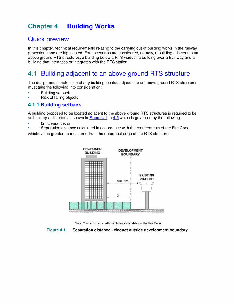
A building proposed to be located adjacent to the above ground RTS structures is required to be setback by a distance as shown in Figure 4-1 to 4-5 which is governed by the following:
• 6m clearance; or • Separation distance calculated in accordance with the requirements of the Fire Code
whichever is greater as measured from the outermost edge of the RTS structures.
Figure 4-1 Separation distance - viaduct outside development boundary
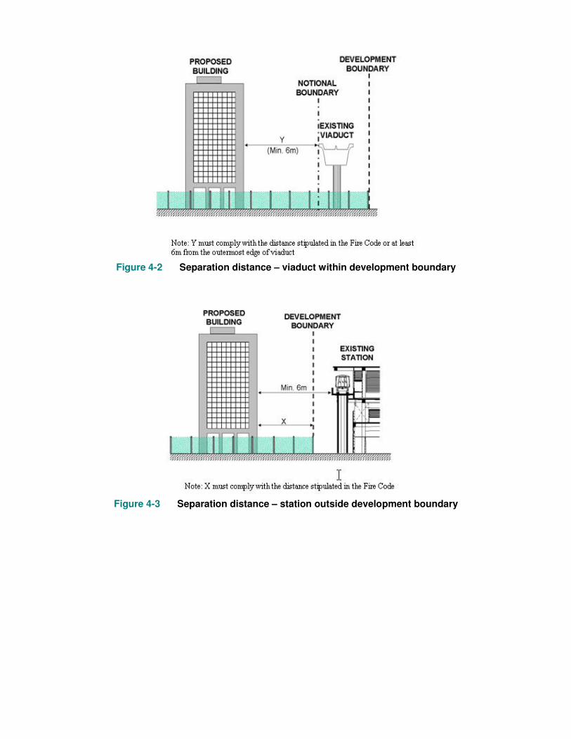
Figure 4-2 Separation distance – viaduct within development boundary
Figure 4-3 Separation distance – station outside development boundary
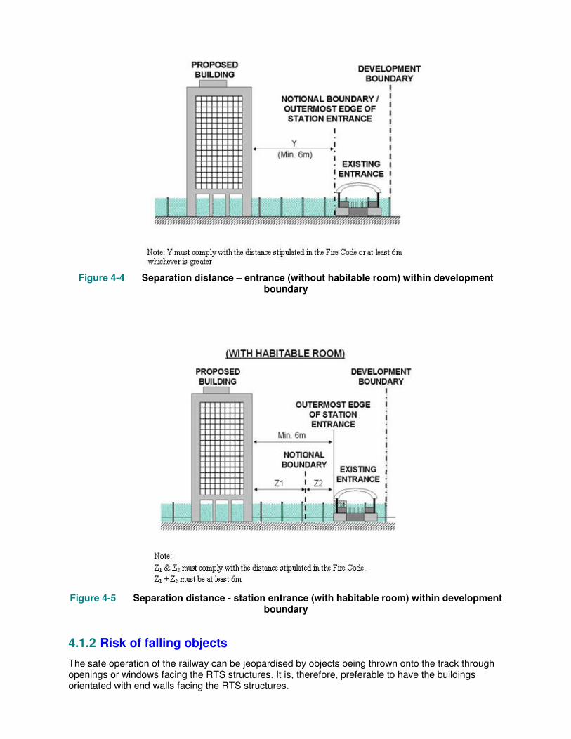
Figure 4-4 Separation distance – entrance (without habitable room) within development
boundary
Figure 4-5 Separation distance - station entrance (with habitable room) within development
boundary
4.1.2 Risk of falling objects
The safe operation of the railway can be jeopardised by objects being thrown onto the track through openings or windows facing the RTS structures. It is, therefore, preferable to have the buildings orientated with end walls facing the RTS structures.

Where it is unavoidable to have the building with openings facing the RTS structures, adequate measures should be implemented to mitigate the risk of fallings objects, litters, etc. (see Figures 4-6 and 4-7).
Figure 4-6 A multi-storey car park with facade opening facing the viaduct is provided with a
protective screen
Figure 4-7 A multi-storey car park with facade opening facing the viaduct is provided with a
protective screen
4.2 Building under a RTS viaduct
The design and construction of a building under the viaduct must:
• Not affect the existing fire fighting facilities. • Provide a 25mm thick plaster to RTS columns enclosed within the building. • Provide 2-hour fire rated wall and roof within 6m from the edge of the viaduct. The fire rated
wall must meet the criteria of stability, integrity and insulation. If sprinkler protection is provided, the fire resistance rating can be reduced to at least 1 hour (see Figure 4-8). There must be no opening on the fire-rated roof. For windows and other openings on the fire-rated walls, 2-hour fire rated doors or shutters must be provided.

• Provide an automatic fire sprinkler system to building with compartment larger than 150m2 and below 4000m2. It must conform to SS CP 52 with pump sized according to design flow and pressure. A storage tank of minimum 30 minutes water supply (see Figure 4-9(a)) is to be provided. For building with compartment larger than 4000m2, the sprinkler system must be designed to meet the requirements of the Fire Code (see Figure 4-9(b)).
• Provide an automatic fire alarm system (see Figure 4-10). • No liquefied petroleum gas is used or flammable liquid or highly combustible substances are
stored (see Figure 4-11). • Provide gas monitoring system consisting of a safety cut-off valve that also interlocked with
the fire alarm system for development that uses low-pressure gas. • Equip cooking facilities and kitchen hood (if any) with automatic fire extinguishing system.
(see Figure 4-12) • Engage a qualified person to carry out annual testing of the automatic fire protection and
detection systems, fire safety measures, gas monitoring system, etc. • Allow at least 0.75m clear distance below the viaduct beam soffit level. • Not to place equipment such as air-con condenser above the building roof. • Provide proper access for the inspection and maintenance of the RTS structures. • Not transfer any loading on to the RTS structures including that arising from any viaduct
bearing replacement. • Ensure that building drainage system does not discharge into the viaduct drainage system. • Ensure that viaduct drainage and lightning protection systems, if affected, are suitably
diverted, reinstated and tested.
The space beneath the viaduct can be used for commercial, institutional and other purposes as shown in Figures 4-13 to 4-21.
Figure 4-8 Fire separation for building under RTS viaduct
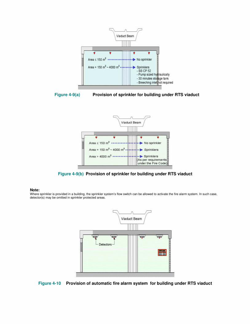
Figure 4-9(a) Provision of sprinkler for building under RTS viaduct
Figure 4-9(b) Provision of sprinkler for building under RTS viaduct
Note: Where sprinkler is provided in a building, the sprinkler system’s flow switch can be allowed to activate the fire alarm system. In such case, detector(s) may be omitted in sprinkler protected areas.
Figure 4-10 Provision of automatic fire alarm system for building under RTS viaduct
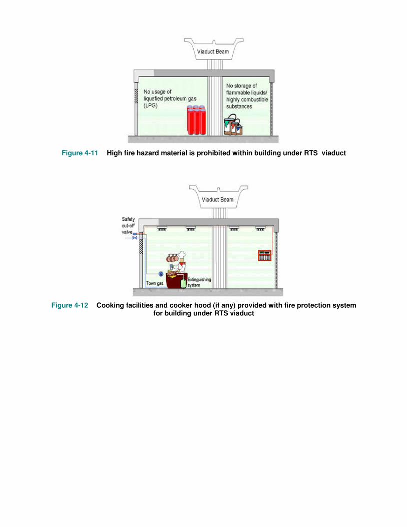
Figure 4-11 High fire hazard material is prohibited within building under RTS viaduct
Figure 4-12 Cooking facilities and cooker hood (if any) provided with fire protection system
for building under RTS viaduct

Figure 4-13 A convenience store located under the viaduct
Figure 4-14 Land below the viaduct can be used to locate shops
Figure 4-15 Land below the viaduct can be used to locate a café
Figure 4-16 Land below the viaduct can be used to locate an eatery

Figure 4-17 Land below the viaduct can be used to locate a fitness centre/ station
Figure 4-18 Land below the viaduct can be used to locate a park

Figure 4-19 Land below the viaduct can be used to locate a children playground
Figure 4-20 Land below the viaduct can be used to locate a bicycle park
Figure 4-21 Land below the viaduct can be used to locate a linkway
4.3 Building over the trainway
A proposed building to be constructed over the trainway (see Figures 4-22 and 4-23) must provide the following to safeguard the trainway:
• 4-hour fire resistance to elements of structure around the trainway. • Emergency ventilation, emergency lighting, dry main system and signages, etc. within the
trainway complying with the Standard for Fire Safety in Rapid Transit Systems. • Adequate space around the trainway to satisfy structural gauge clearance, space for viaduct
beam replacement. • Adequate screening of windows or openings of building facing the RTS structures.
Figure 4-22 Fire safety requirements for building above and around RTS viaduct
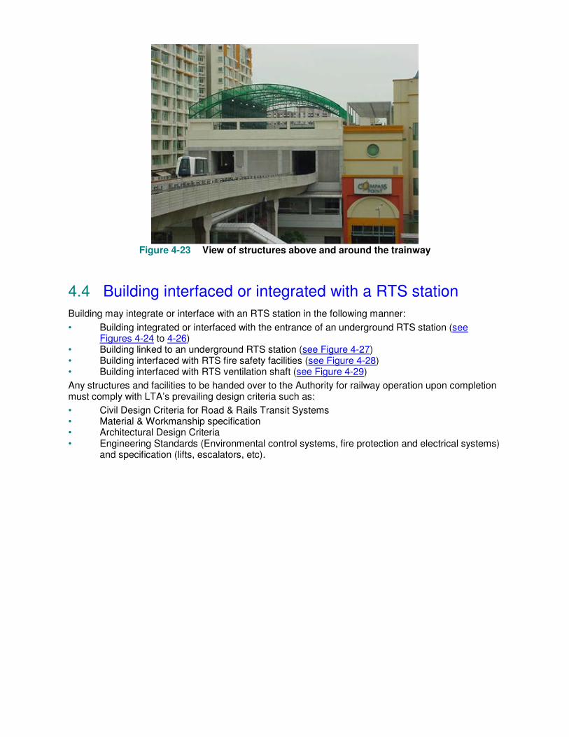
Figure 4-23 View of structures above and around the trainway
4.4 Building interfaced or integrated with a RTS station
Building may integrate or interface with an RTS station in the following manner:
• Building integrated or interfaced with the entrance of an underground RTS station (see Figures 4-24 to 4-26)
• Building linked to an underground RTS station (see Figure 4-27) • Building interfaced with RTS fire safety facilities (see Figure 4-28) • Building interfaced with RTS ventilation shaft (see Figure 4-29)
Any structures and facilities to be handed over to the Authority for railway operation upon completion must comply with LTA’s prevailing design criteria such as:
• Civil Design Criteria for Road & Rails Transit Systems • Material & Workmanship specification • Architectural Design Criteria • Engineering Standards (Environmental control systems, fire protection and electrical systems)
and specification (lifts, escalators, etc).

Figure 4-24 Development integrated with the entrance of an underground RTS station
Figure 4-25 Development integrated with an entrance of an underground RTS station

Figure 4-26 Development integrated with an entrance of an underground RTS station
Figure 4-27 Development linked to an underground RTS station
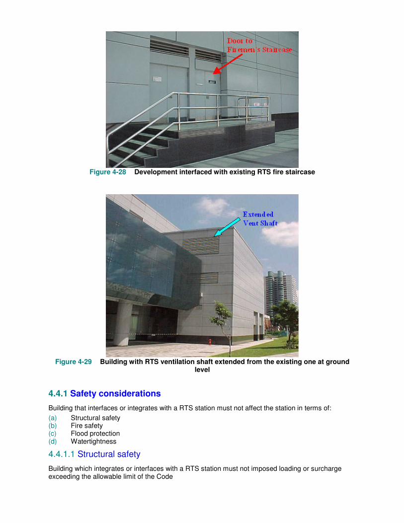
Figure 4-28 Development interfaced with existing RTS fire staircase
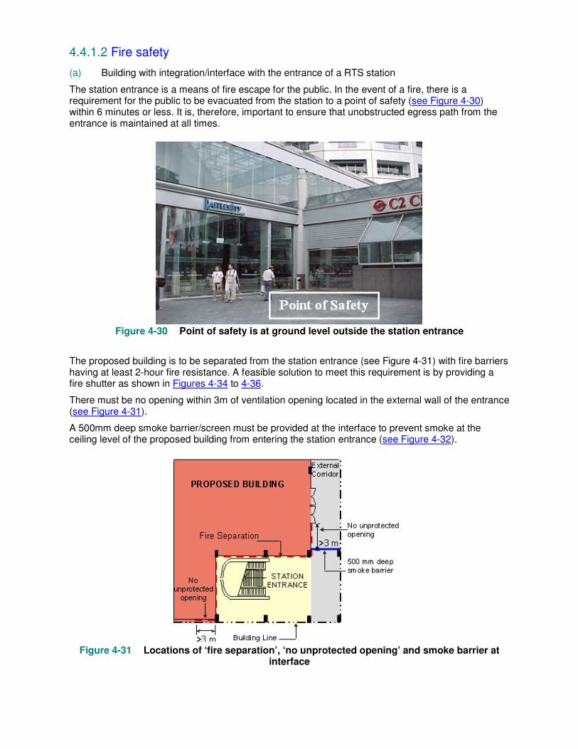
Figure 4-29 Building with RTS ventilation shaft extended from the existing one at ground
level
4.4.1 Safety considerations
Building that interfaces or integrates with a RTS station must not affect the station in terms of:
(a) Structural safety (b) Fire safety (c) Flood protection (d) Watertightness
4.4.1.1 Structural safety
Building which integrates or interfaces with a RTS station must not imposed loading or surcharge exceeding the allowable limit of the Code
4.4.1.2 Fire safety
(a) Building with integration/interface with the entrance of a RTS station
The station entrance is a means of fire escape for the public. In the event of a fire, there is a requirement for the public to be evacuated from the station to a point of safety (see Figure 4-30) within 6 minutes or less. It is, therefore, important to ensure that unobstructed egress path from the entrance is maintained at all times.
Figure 4-30 Point of safety is at ground level outside the station entrance
The proposed building is to be separated from the station entrance (see Figure 4-31) with fire barriers having at least 2-hour fire resistance. A feasible solution to meet this requirement is by providing a fire shutter as shown in Figures 4-34 to 4-36.
There must be no opening within 3m of ventilation opening located in the external wall of the entrance (see Figure 4-31).
A 500mm deep smoke barrier/screen must be provided at the interface to prevent smoke at the ceiling level of the proposed building from entering the station entrance (see Figure 4-32).
Figure 4-31 Locations of ‘fire separation’, ‘no unprotected opening’ and smoke barrier at
interface

Figure 4-32 Provision of smoke barrier at interface
Where an automatic fire shutter is provided, it must be:
• activated by smoke detectors installed at both sides of fire shutter. • activated by fire alarm of the zone immediately next to the opening in the development. • activated by station’s public area fire alarm. • status (open/ close) of the fire shutter monitored at Passenger Service Centre of the RTS
station. • maintained regularly and tested annually by a qualified person.
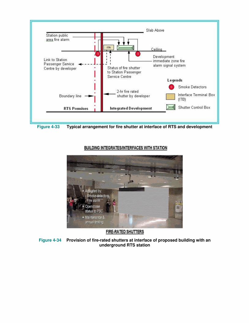
Figure 4-33 Typical arrangement for fire shutter at interface of RTS and development
Figure 4-34 Provision of fire-rated shutters at interface of proposed building with an
underground RTS station
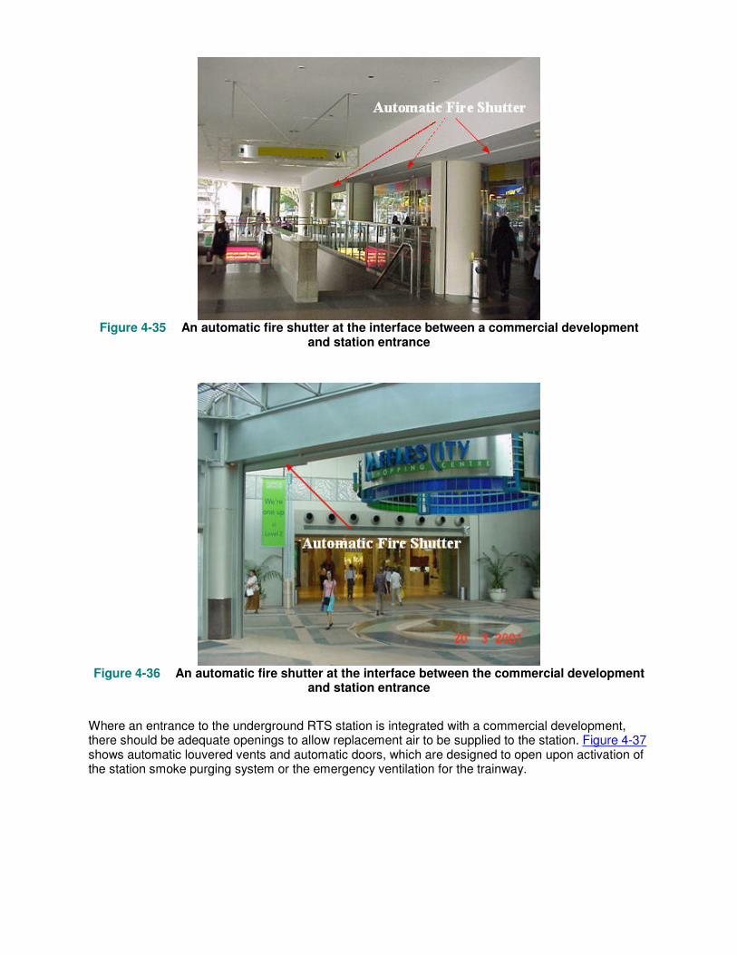
Figure 4-35 An automatic fire shutter at the interface between a commercial development
and station entrance
Figure 4-36 An automatic fire shutter at the interface between the commercial development
and station entrance
Where an entrance to the underground RTS station is integrated with a commercial development, there should be adequate openings to allow replacement air to be supplied to the station. Figure 4-37 shows automatic louvered vents and automatic doors, which are designed to open upon activation of the station smoke purging system or the emergency ventilation for the trainway.
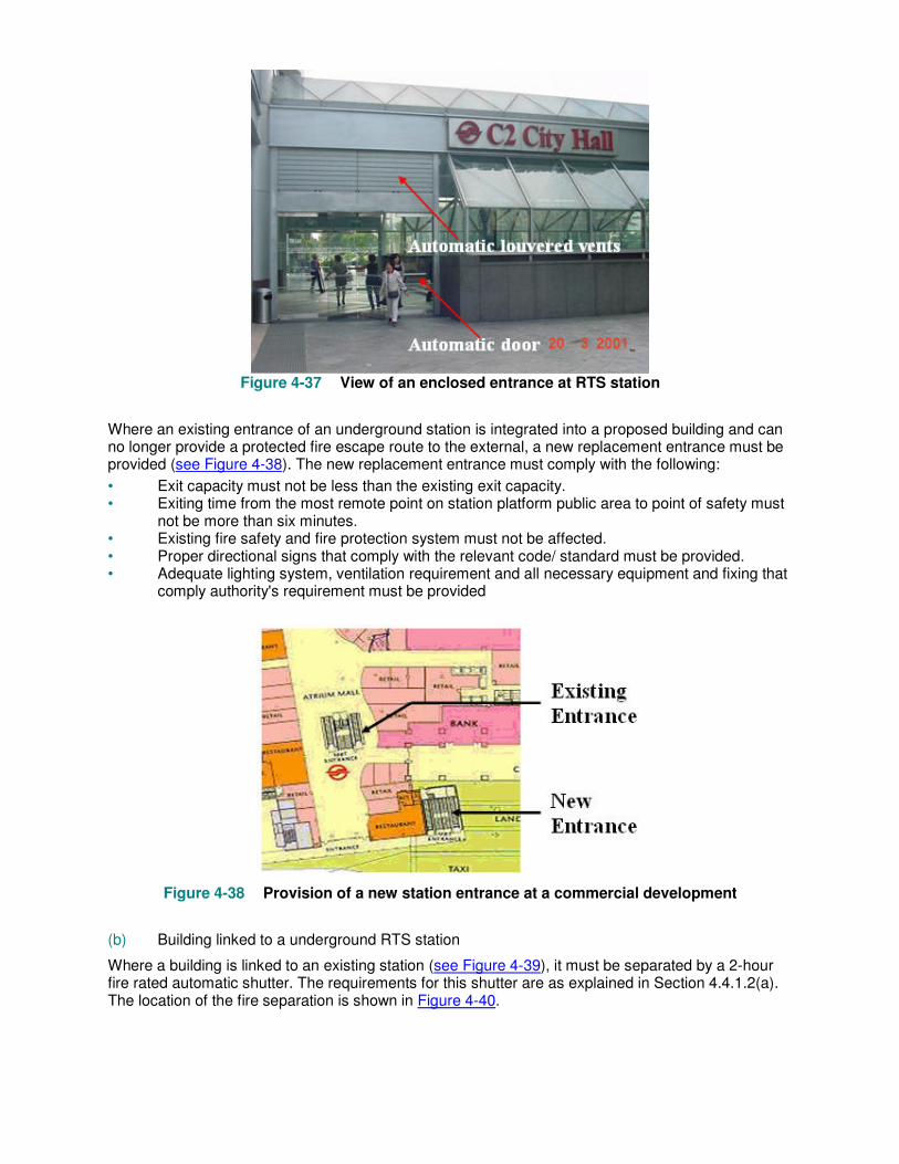
Figure 4-37 View of an enclosed entrance at RTS station
Where an existing entrance of an underground station is integrated into a proposed building and can no longer provide a protected fire escape route to the external, a new replacement entrance must be provided (see Figure 4-38). The new replacement entrance must comply with the following:
• Exit capacity must not be less than the existing exit capacity. • Exiting time from the most remote point on station platform public area to point of safety must
not be more than six minutes. • Existing fire safety and fire protection system must not be affected. • Proper directional signs that comply with the relevant code/ standard must be provided. • Adequate lighting system, ventilation requirement and all necessary equipment and fixing that
comply authority's requirement must be provided
Figure 4-38 Provision of a new station entrance at a commercial development
(b) Building linked to a underground RTS station
Where a building is linked to an existing station (see Figure 4-39), it must be separated by a 2-hour fire rated automatic shutter. The requirements for this shutter are as explained in Section 4.4.1.2(a). The location of the fire separation is shown in Figure 4-40.
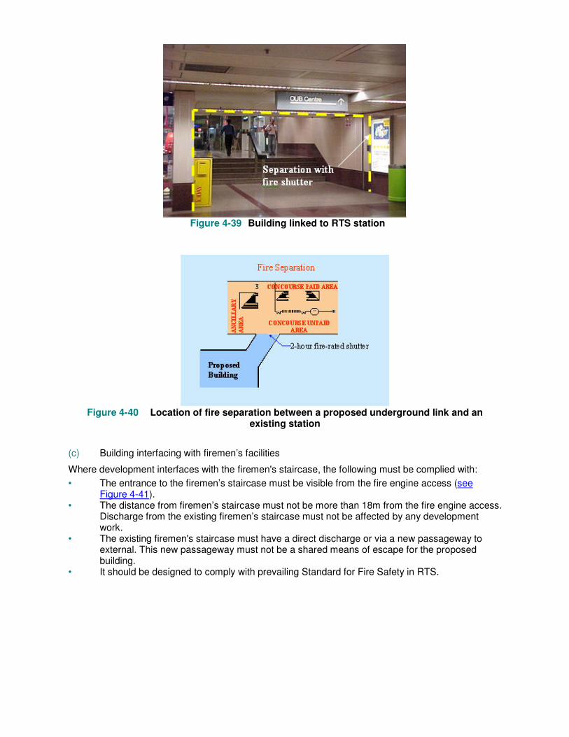
Figure 4-39 Building linked to RTS station
Figure 4-40 Location of fire separation between a proposed underground link and an
existing station
(c) Building interfacing with firemen’s facilities
Where development interfaces with the firemen's staircase, the following must be complied with:
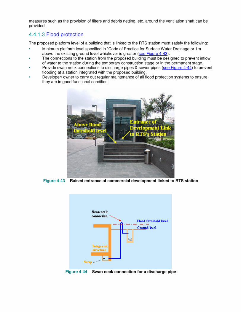
• The entrance to the firemen’s staircase must be visible from the fire engine access (see Figure 4-41).
• The distance from firemen’s staircase must not be more than 18m from the fire engine access. Discharge from the existing firemen’s staircase must not be affected by any development work.
• The existing firemen's staircase must have a direct discharge or via a new passageway to external. This new passageway must not be a shared means of escape for the proposed building.
• It should be designed to comply with prevailing Standard for Fire Safety in RTS.
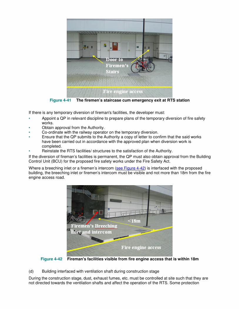
Figure 4-41 The firemen’s staircase cum emergency exit at RTS station
If there is any temporary diversion of fireman's facilities, the developer must:
• Appoint a QP in relevant discipline to prepare plans of the temporary diversion of fire safety works.
• Obtain approval from the Authority. • Co-ordinate with the railway operator on the temporary diversion. • Ensure that the QP submits to the Authority a copy of letter to confirm that the said works
have been carried out in accordance with the approved plan when diversion work is completed.
• Reinstate the RTS facilities/ structures to the satisfaction of the Authority.
If the diversion of fireman’s facilities is permanent, the QP must also obtain approval from the Building Control Unit (BCU) for the proposed fire safety works under the Fire Safety Act.
Where a breeching inlet or a firemen’s intercom (see Figure 4-42) is interfaced with the proposed building, the breeching inlet or firemen’s intercom must be visible and not more than 18m from the fire engine access road.
Figure 4-42 Fireman's facilities visible from fire engine access that is within 18m
(d) Building interfaced with ventilation shaft during construction stage
During the construction stage, dust, exhaust fumes, etc. must be controlled at site such that they are not directed towards the ventilation shafts and affect the operation of the RTS. Some protection
measures such as the provision of filters and debris netting, etc. around the ventilation shaft can be provided.
4.4.1.3 Flood protection
The proposed platform level of a building that is linked to the RTS station must satisfy the following:
• Minimum platform level specified in "Code of Practice for Surface Water Drainage or 1m above the existing ground level whichever is greater (see Figure 4-43).
• The connections to the station from the proposed building must be designed to prevent inflow of water to the station during the temporary construction stage or in the permanent stage.
• Provide swan neck connections to discharge pipes & sewer pipes (see Figure 4-44) to prevent flooding at a station integrated with the proposed building.
• Developer/ owner to carry out regular maintenance of all flood protection systems to ensure they are in good functional condition.
Figure 4-43 Raised entrance at commercial development linked to RTS station
Figure 4-44 Swan neck connection for a discharge pipe
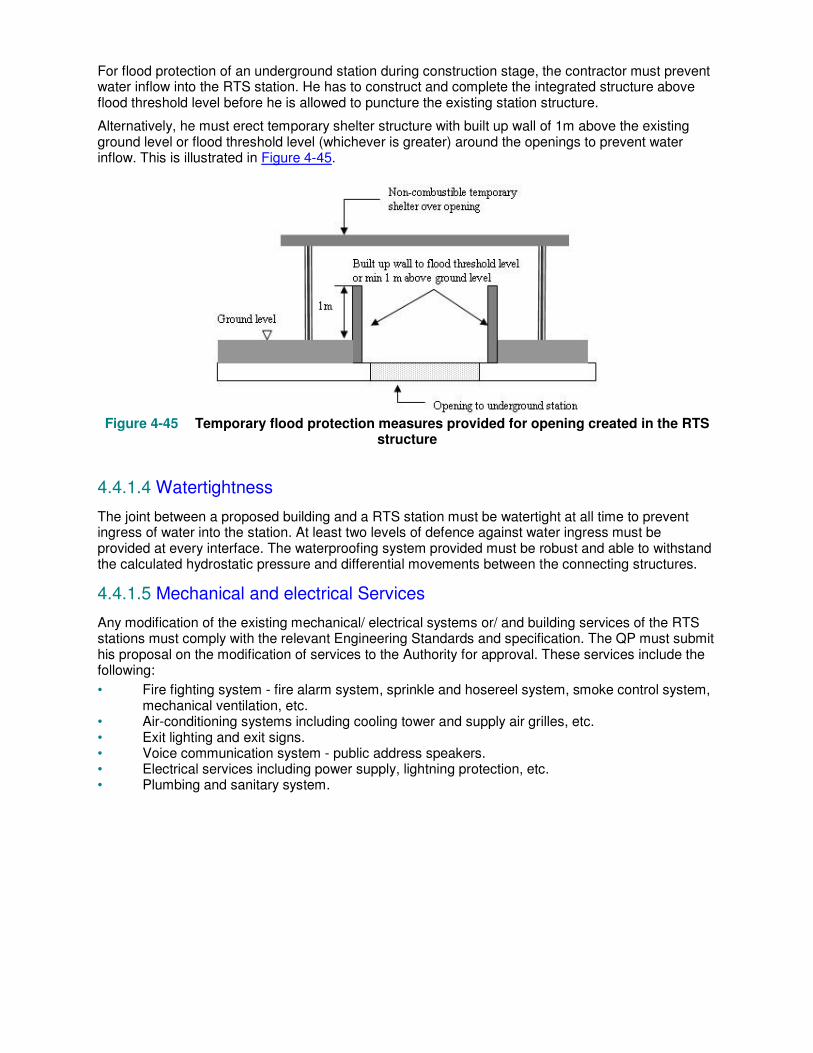
For flood protection of an underground station during construction stage, the contractor must prevent water inflow into the RTS station. He has to construct and complete the integrated structure above flood threshold level before he is allowed to puncture the existing station structure.
Alternatively, he must erect temporary shelter structure with built up wall of 1m above the existing ground level or flood threshold level (whichever is greater) around the openings to prevent water inflow. This is illustrated in Figure 4-45.
Figure 4-45 Temporary flood protection measures provided for opening created in the RTS
structure
4.4.1.4 Watertightness
The joint between a proposed building and a RTS station must be watertight at all time to prevent ingress of water into the station. At least two levels of defence against water ingress must be provided at every interface. The waterproofing system provided must be robust and able to withstand the calculated hydrostatic pressure and differential movements between the connecting structures.
4.4.1.5 Mechanical and electrical Services
Any modification of the existing mechanical/ electrical systems or/ and building services of the RTS stations must comply with the relevant Engineering Standards and specification. The QP must submit his proposal on the modification of services to the Authority for approval. These services include the following:
• Fire fighting system - fire alarm system, sprinkle and hosereel system, smoke control system, mechanical ventilation, etc.
• Air-conditioning systems including cooling tower and supply air grilles, etc. • Exit lighting and exit signs. • Voice communication system - public address speakers. • Electrical services including power supply, lightning protection, etc. • Plumbing and sanitary system.

Chapter 5 Instrumentation
Quick preview
Instrumentation is an important provision for monitoring the effects of engineering works. It has to be effective to capture the changes in ground conditions and the effects on RTS. This will require understanding of the design of the RTS, the ground conditions in its vicinity and the critical areas to monitor. In this chapter, the considerations for planning instrumentation proposal are discussed. Key criteria for monitoring RTS will be explained with examples of typical instrumentation for monitoring. Some case studies for past development sites within the railway protection zone are also included to illustrate compliance with the Code for different situations.
5.1 Introduction
5.1.1
Instrumentation monitoring is an indispensable component of engineering works particularly within the railway protection zone for various reasons including the following:
• verify design calculations and predictions • ensure public safety is not compromised • as a design tool to moderate under or over provisions of engineering measures • enable remedial measures to be taken in time
5.1.2
Engineering calculations are just tools for predictions. Software has limited ability to model complex ground conditions. Inaccuracies will arise depending on the assumptions made, numerical models, selection of parameters, and etc. As such, actual results may deviate significantly from that predicted. Instrumentation provides a direct method for checking the impact of works on to RTS due to the construction activities. With monitoring, there is advance warning of impending failure or adverse changes.
5.1.3
Instrumentation should be planned with the objective in mind. The type of instrument and spacing should be appropriate to capture the critical situation. It is also important to establish monitoring criteria as a basis for monitoring and frequency of monitoring that tie-in with the engineering work.
5.2 Planning Considerations
5.2.1
A number of considerations should be bore in mind when planning the instrumentation proposal. These include:
• Ground conditions • Development proposal • Construction activities • Type of RTS structure & its foundation • Past movement recorded by RTS structure and its track caused by adjacent developments
Some typical monitoring frequencies are shown in Tables 5-1.
5.2.2
The ground needs to be monitored as its compressibility has impact on the stability of RTS structures and its deformation and hence could affect the safe operation of railway. How RTS structures are
affected by the works also depend on the type of RTS foundation; whether they are supported on piles or directly on the ground.
5.2.3
Instrumentation is provided to monitor the construction activities. The construction activities could be planned and sequenced by adopting methods which minimises adverse effects such as ground displacement, settlement, ground water lowering, vibration, etc. By doing so, some monitoring instruments may be omitted. For example, if the demolition work is carried out using crusher, and the vibration impact due to the works can be controlled, vibration monitoring may not be needed. Vibration monitoring would not be need if oscillator instead of vibro-hammer is used for pile installation.
5.2.4
It should be noted that track access to underground RTS structure is limited to non-operation hours and its booking is subject to availability and approval from railway operator. It is recommended to install automatic type instruments in the train way whenever possible to minimise track access.
5.2.5
There should be redundancy in the provision of instrument to cater for possible damage and for comparisons. Instruments should be protected and located such that it will not suffer damage from construction activities.
5.2.6
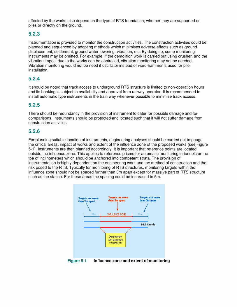
For planning suitable location of instruments, engineering analyses should be carried out to gauge the critical areas, impact of works and extent of the influence zone of the proposed works (see Figure 5-1). Instruments are then planned accordingly. It is important that reference points are located outside the influence zone. This applies to reference prisms for automatic monitoring in tunnels or the toe of inclinometers which should be anchored into competent strata. The provision of instrumentation is highly dependent on the engineering work and the method of construction and the risk posed to the RTS. Typically for monitoring of RTS structures, monitoring targets within the influence zone should not be spaced further than 3m apart except for massive part of RTS structure such as the station. For these areas the spacing could be increased to 5m.
Figure 5-1 Influence zone and extent of monitoring

5.2.7
Wherever possible, the prisms and protectors should be located close to the rails to prevent tripping hazards. Prism protectors on the floor should also be coated with luminous paint to enhance visibility. For NEL system for which the power supply and the pantograph are located overhead at the tunnel crown, prisms should not be installed near the pantograph whenever possible.
5.2.8
It is highlighted that should the predicted cumulative movement for underground or at grade RTS structure inclusive of past displacements exceed 5mm, automatic monitoring shall be provided. If manual survey monitoring is provided and results subsequently show that the assessment for movement of RTS structure due to the works is under predicted, engineering work shall stop immediately and to be made safe. Work shall not recommence until the automatic remote control monitoring system is commissioned incorporating the displacements which had occurred. Automatic monitoring of above ground RTS structure and monitoring of its track is typically not required except for critical cases where the RTS structure is located in compressible ground and basement excavation is deeper than 3m.
5.2.9
Before instruments are commissioned, there should be verification tests to ensure the instrument provides reliable readings. This could be done for example using a calibrated load cell for strain gauge monitoring.
5.2.10
In cases where the impact of engineering works onto the RTS may be varied, say due to variability of ground conditions, complexity of engineering proposal, monitoring instruments provided has to be automatic to enable rapid response and control over the engineering works before it is too late.
5.2.11
Some parts of the RTS structures had experienced displacement, settlement and distortion due to past construction activities and development works. The instrument proposal must incorporate these movements into the monitoring scheme and the RTS structures and tracks must be monitored on criteria based on cumulative basis.
5.2.12
Combustible materials must not be used for construction of fixtures and instruments to prevent fire hazard. This includes power and signal cables which should be made of fire retardant, low smoke, halogen free materials. An example of acceptable fixtures is by using pre-fabricated welded brackets with bolted connections to the RTS structure. In-situ welding is not allowed and the anchoring system must be robust, designed for redundancy and for failure of any anchorage or bolt (see Figure 5-2).
5.2.13
Monitoring instruments may need to be removed for periodic servicing and maintenance or to be replaced when faulty. The monitoring proposal must have a procedure to carry this out without affecting and changing the monitoring results.
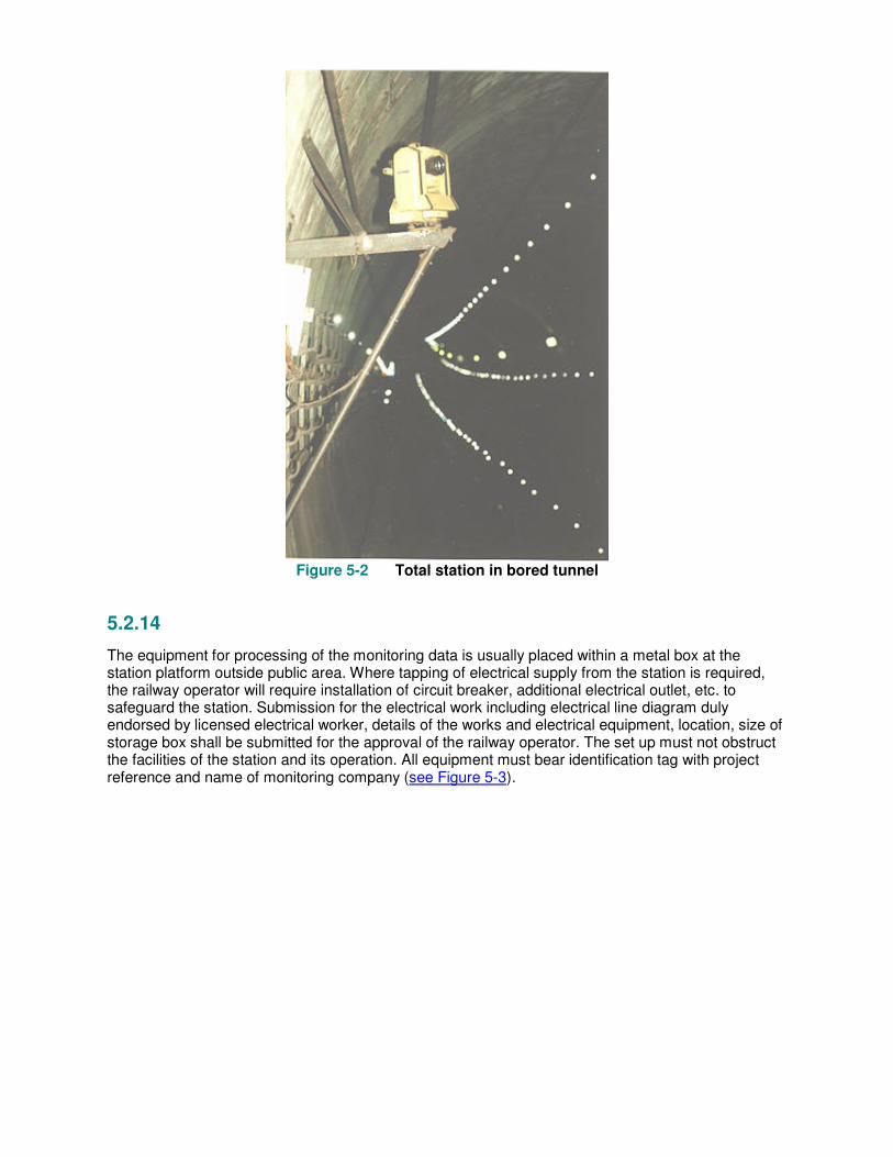
Figure 5-2 Total station in bored tunnel
5.2.14
The equipment for processing of the monitoring data is usually placed within a metal box at the station platform outside public area. Where tapping of electrical supply from the station is required, the railway operator will require installation of circuit breaker, additional electrical outlet, etc. to safeguard the station. Submission for the electrical work including electrical line diagram duly endorsed by licensed electrical worker, details of the works and electrical equipment, location, size of storage box shall be submitted for the approval of the railway operator. The set up must not obstruct the facilities of the station and its operation. All equipment must bear identification tag with project reference and name of monitoring company (see Figure 5-3).
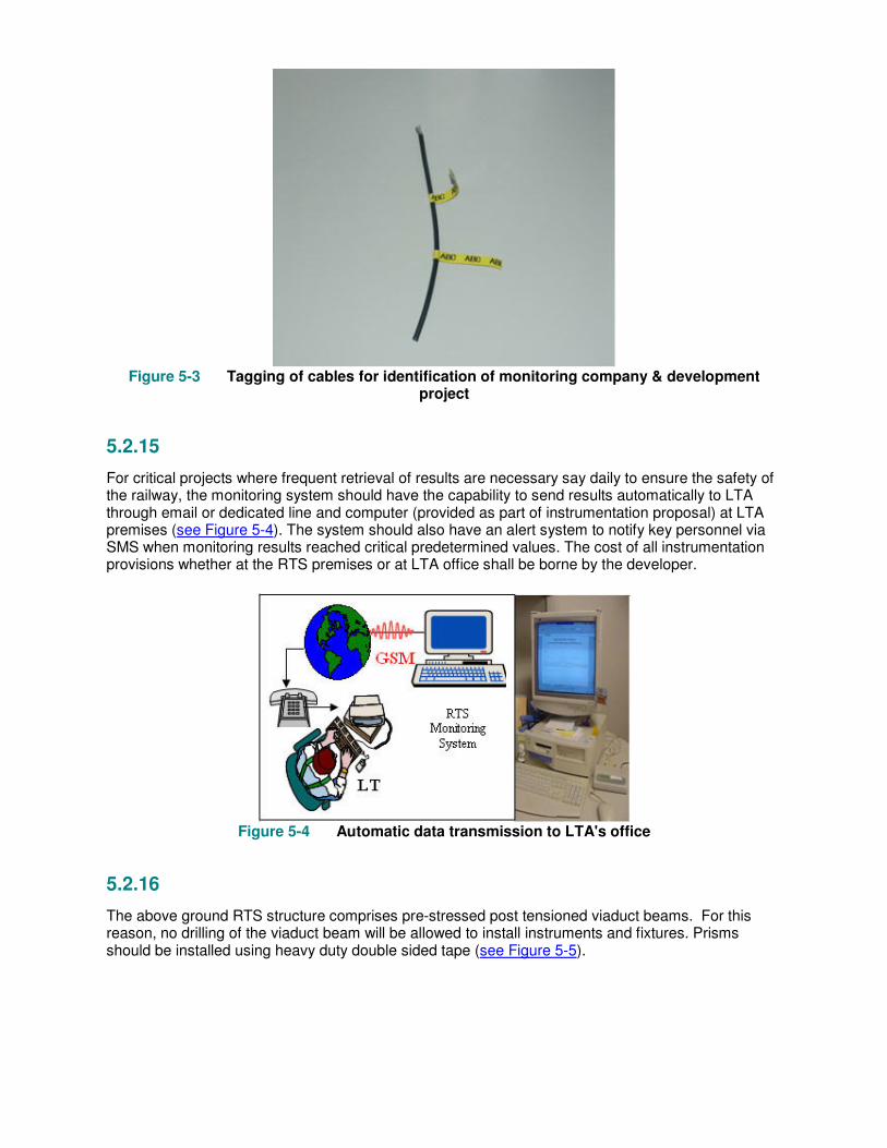
Figure 5-3 Tagging of cables for identification of monitoring company & development
project
5.2.15
For critical projects where frequent retrieval of results are necessary say daily to ensure the safety of the railway, the monitoring system should have the capability to send results automatically to LTA through email or dedicated line and computer (provided as part of instrumentation proposal) at LTA premises (see Figure 5-4). The system should also have an alert system to notify key personnel via SMS when monitoring results reached critical predetermined values. The cost of all instrumentation provisions whether at the RTS premises or at LTA office shall be borne by the developer.
Figure 5-4 Automatic data transmission to LTA's office
5.2.16
The above ground RTS structure comprises pre-stressed post tensioned viaduct beams. For this reason, no drilling of the viaduct beam will be allowed to install instruments and fixtures. Prisms should be installed using heavy duty double sided tape (see Figure 5-5).

Figure 5-5 Prisms installed in viaduct beam soffit
5.3 Criteria for Monitoring
5.3.1 Ground and RTS structure monitoring
5.3.1.1
Ground displacements and change in ground conditions depend on the engineering work proposal. QP has to assess the influence zone (see Figure 5-1) and provide design and allowable values for each stage of work. The assessment must take into consideration the location of instruments in the assessment of results.
5.3.2 Structure & track limits
5.3.2.1
The allowable limits for RTS structures and tracks are shown in Tables 9.1(b) to 9.1(e) of the Code. Where no allowable limit is provided, the allowable limits for movement of structure and track shall be assessed by a QP and submitted for acceptance.
5.4 Monitoring of RTS Structure
5.4.1 Total movement in any direction (underground RTS)
5.4.1.1
Total movement refers to the bodily displacement of the RTS structure or track. An example is illustrated in Figure 5-6 for point A. The resultant displacement, m1 comprising components x1 and y1 must be less than the allowable value.
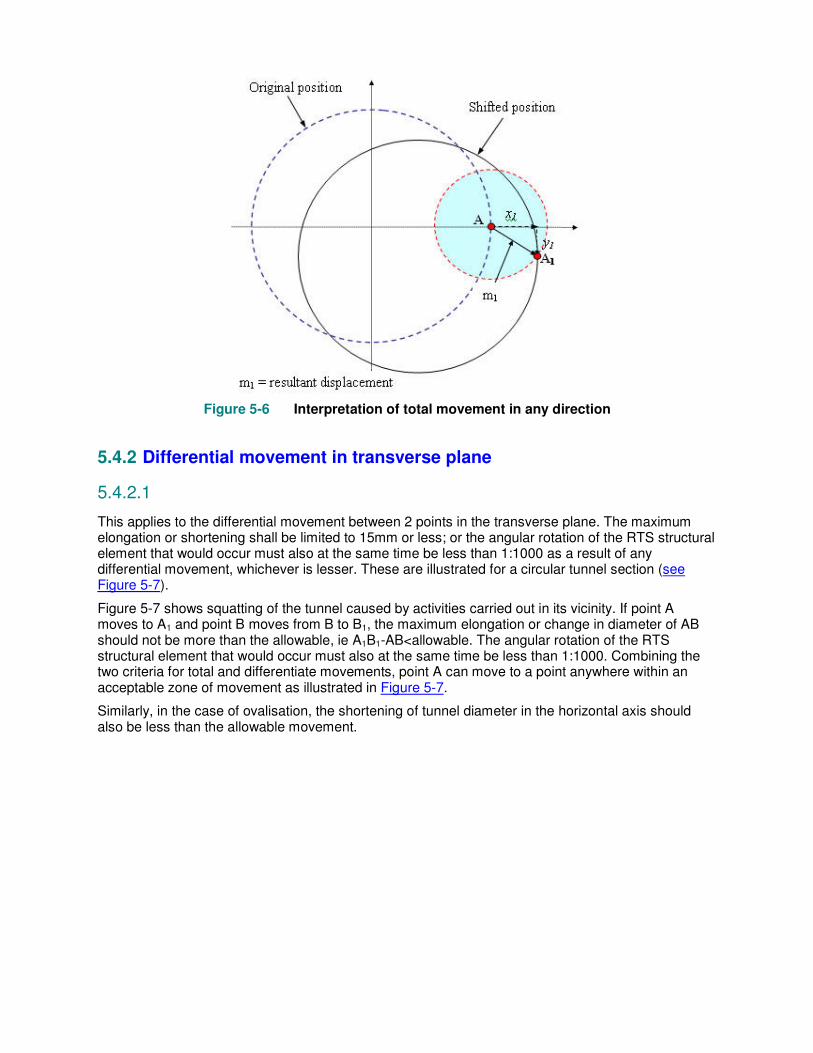
Figure 5-6 Interpretation of total movement in any direction
5.4.2 Differential movement in transverse plane
5.4.2.1
This applies to the differential movement between 2 points in the transverse plane. The maximum elongation or shortening shall be limited to 15mm or less; or the angular rotation of the RTS structural element that would occur must also at the same time be less than 1:1000 as a result of any differential movement, whichever is lesser. These are illustrated for a circular tunnel section (see Figure 5-7).
Figure 5-7 shows squatting of the tunnel caused by activities carried out in its vicinity. If point A moves to A1 and point B moves from B to B1, the maximum elongation or change in diameter of AB should not be more than the allowable, ie A1B1-AB<allowable. The angular rotation of the RTS structural element that would occur must also at the same time be less than 1:1000. Combining the two criteria for total and differentiate movements, point A can move to a point anywhere within an acceptable zone of movement as illustrated in Figure 5-7.
Similarly, in the case of ovalisation, the shortening of tunnel diameter in the horizontal axis should also be less than the allowable movement.
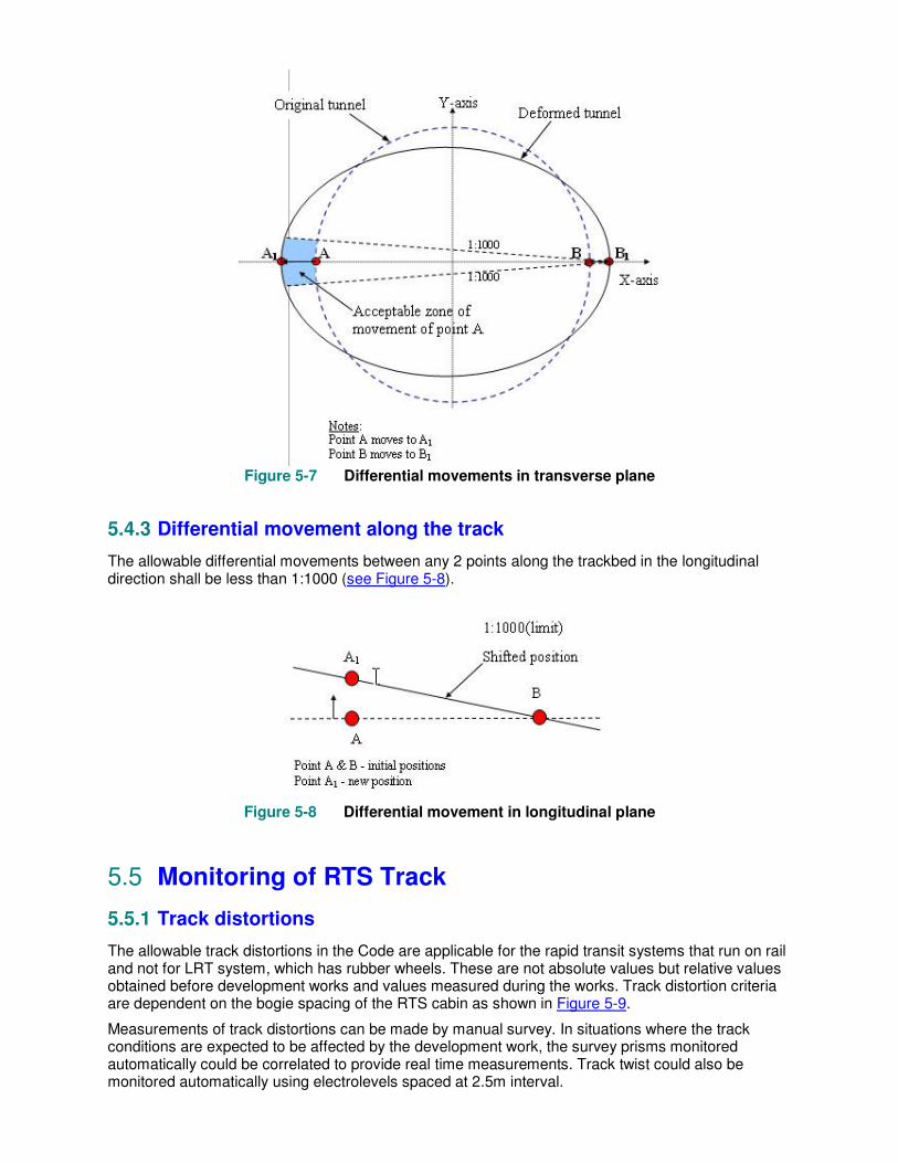
Figure 5-7 Differential movements in transverse plane
5.4.3 Differential movement along the track
The allowable differential movements between any 2 points along the trackbed in the longitudinal direction shall be less than 1:1000 (see Figure 5-8).
Figure 5-8 Differential movement in longitudinal plane
5.5 Monitoring of RTS Track
5.5.1 Track distortions
The allowable track distortions in the Code are applicable for the rapid transit systems that run on rail and not for LRT system, which has rubber wheels. These are not absolute values but relative values obtained before development works and values measured during the works. Track distortion criteria are dependent on the bogie spacing of the RTS cabin as shown in Figure 5-9.
Measurements of track distortions can be made by manual survey. In situations where the track conditions are expected to be affected by the development work, the survey prisms monitored automatically could be correlated to provide real time measurements. Track twist could also be monitored automatically using electrolevels spaced at 2.5m interval.
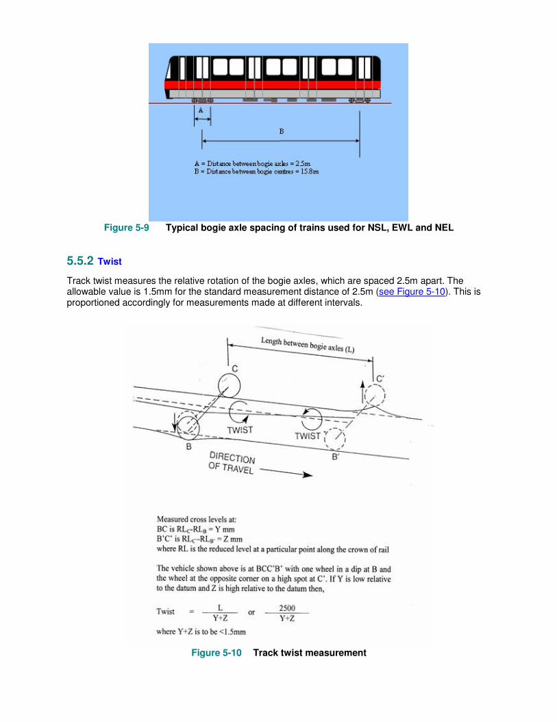
Figure 5-9 Typical bogie axle spacing of trains used for NSL, EWL and NEL
5.5.2 Twist
Track twist measures the relative rotation of the bogie axles, which are spaced 2.5m apart. The allowable value is 1.5mm for the standard measurement distance of 2.5m (see Figure 5-10). This is proportioned accordingly for measurements made at different intervals.
Figure 5-10 Track twist measurement

5.5.3 Vertical dip or peak
This is a measurement of the vertical distortion of the rail over a chord length of 5m. The average value for both rails is used to check against the allowable value (see Figure 5-11).
Figure 5-11 Vertical dip or peak measurement
5.5.4 Horizontal versine
Similar to vertical peak or dip, horizontal versine is a measurement of the change in horizontal curvature over a 16m chord, the distance between two sets of bogies in a carriage (see Figure 5-12). Again the average value for the 2 rails is used. It should be noted that the existing rail may have a design curvature and monitoring is checked based on the change in condition before development work commences.
Figure 5-12 Horizontal verine measured over the centres of 2 sets of bogie spaced at 16m
5.6 Case Studies: Underground RTS
5.6.1
Engineering work comprising construction of bored piles & a basement

5.6.1.1
This subject site is within the 3rd reserve. The engineering works include bored pile installation and the construction of basement involving excavation of about 3m deep. The excavation work is supported by a strutted sheet pile wall system (see Figure 5-13)
5.6.1.2
The subsoil stratum consists of compressible soil of up to 10m overlying residual soil. The ground water level is at about 1m below the existing ground level. Ground instrumentation comprising inclinometers, piezometers, water standpipes and ground settlement monitoring points (see Figure 5-13) were installed to monitor the effects of the substructure work on the adjacent ground.
5.6.1.3
The closer southbound MRT tunnel to site was monitored by manual survey as the predicted movement is less than 5mm (see Figure 5-14). For monitoring of vibration caused by bored piling work, a vibration sensor was installed on the tunnel wall.
Figure 5-13 Layout plan for ground instruments
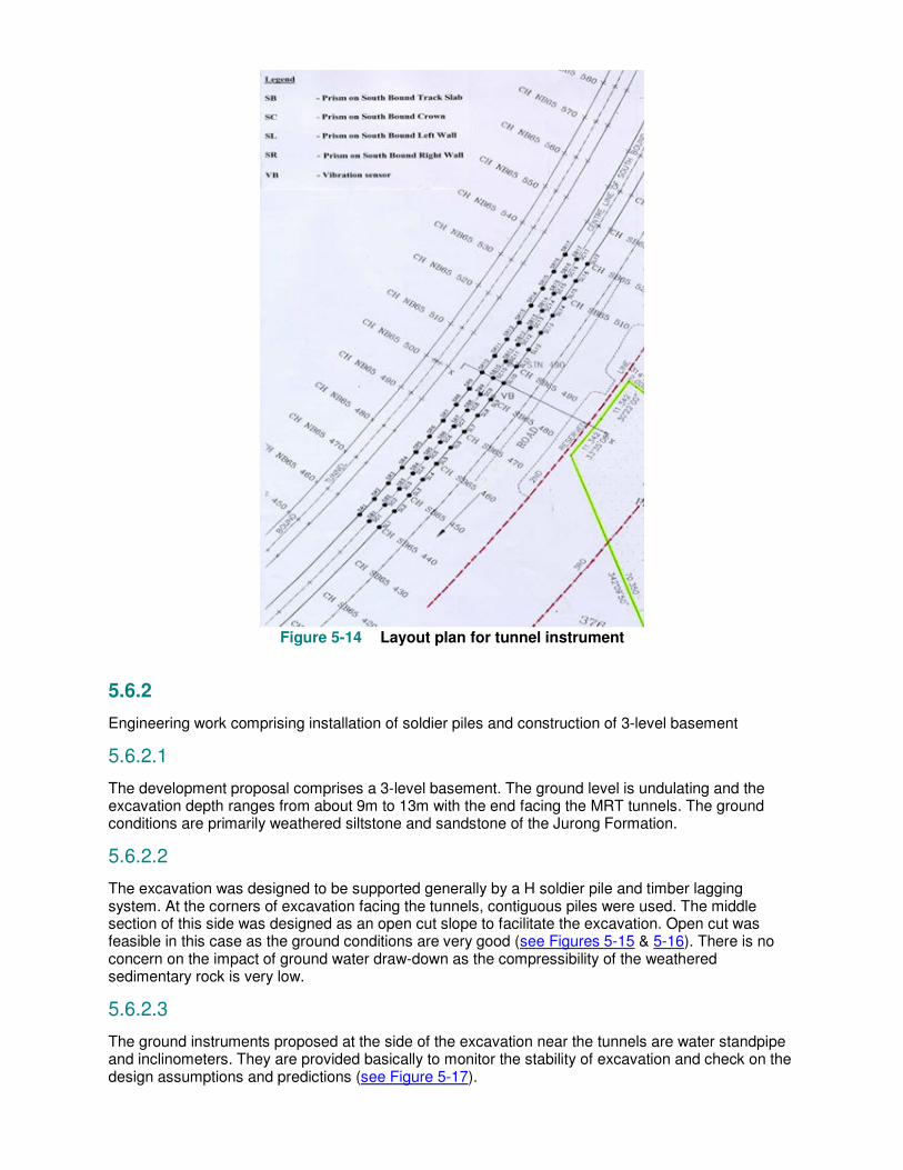
Figure 5-14 Layout plan for tunnel instrument
5.6.2
Engineering work comprising installation of soldier piles and construction of 3-level basement
5.6.2.1
The development proposal comprises a 3-level basement. The ground level is undulating and the excavation depth ranges from about 9m to 13m with the end facing the MRT tunnels. The ground conditions are primarily weathered siltstone and sandstone of the Jurong Formation.
5.6.2.2
The excavation was designed to be supported generally by a H soldier pile and timber lagging system. At the corners of excavation facing the tunnels, contiguous piles were used. The middle section of this side was designed as an open cut slope to facilitate the excavation. Open cut was feasible in this case as the ground conditions are very good (see Figures 5-15 & 5-16). There is no concern on the impact of ground water draw-down as the compressibility of the weathered sedimentary rock is very low.
5.6.2.3
The ground instruments proposed at the side of the excavation near the tunnels are water standpipe and inclinometers. They are provided basically to monitor the stability of excavation and check on the design assumptions and predictions (see Figure 5-17).

5.6.2.4
The tunnel movement was predicted to be 5mm and the nearer North Bound tunnel was to be monitored automatically by a motorised theodolite. The influence zone was assessed to be about 10m from the extreme edge of excavation. Prisms targets were spaced at 3m for this zone. Beyond this zone, prism targets were spaced at 5m and for a distance of 20m.The South Bound tunnel is manually surveyed for tunnel displacement and distortion.
Three electrolevels and a vibration sensor were provided to monitor the track twist and vibration due to the proposed works (see Figure 5-18).
Figure 5-15 Sectional view of excavation at mid section

Figure 5-16 Sectional view of excavation at corners

Figure 5-17 Layout plan of ground instruments
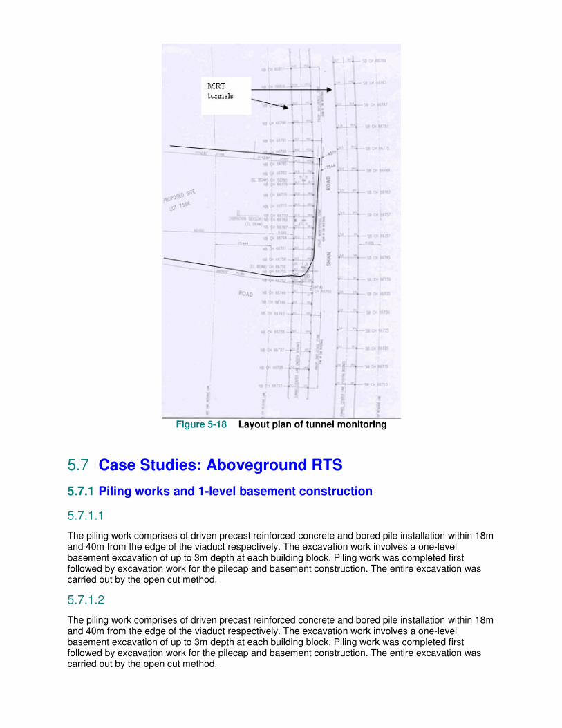
Figure 5-18 Layout plan of tunnel monitoring
5.7 Case Studies: Aboveground RTS
5.7.1 Piling works and 1-level basement construction
5.7.1.1
The piling work comprises of driven precast reinforced concrete and bored pile installation within 18m and 40m from the edge of the viaduct respectively. The excavation work involves a one-level basement excavation of up to 3m depth at each building block. Piling work was completed first followed by excavation work for the pilecap and basement construction. The entire excavation was carried out by the open cut method.
5.7.1.2
The piling work comprises of driven precast reinforced concrete and bored pile installation within 18m and 40m from the edge of the viaduct respectively. The excavation work involves a one-level basement excavation of up to 3m depth at each building block. Piling work was completed first followed by excavation work for the pilecap and basement construction. The entire excavation was carried out by the open cut method.
5.7.1.3
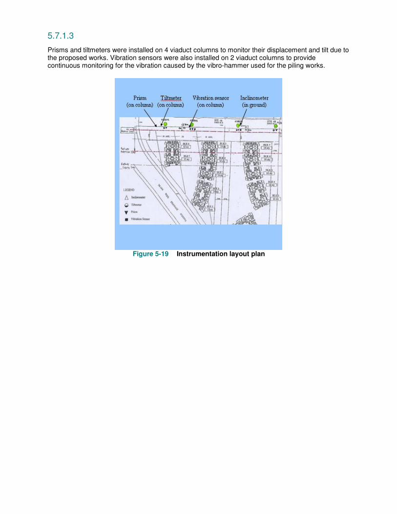
Prisms and tiltmeters were installed on 4 viaduct columns to monitor their displacement and tilt due to the proposed works. Vibration sensors were also installed on 2 viaduct columns to provide continuous monitoring for the vibration caused by the vibro-hammer used for the piling works.
Figure 5-19 Instrumentation layout plan

Table 5-1 Typical instrumentation & frequency for construction activities within the railway protection zone
Type of Instruments Underground,
Transition, Sub-aqueous & At Grade Structures
Above Ground Structures
Inclinometer Daily Twice weekly
Water standpipe Daily Twice weekly
Piezometer Daily Nil (Trice weekly -critical cases only)
Extensometer Daily Nil (Trice weekly - critical cases only)
Gro
und
Surface settlement marker
Daily Nil (Trice weekly -critical cases only)
ATMS Continuous Nil (Continuous -critical cases only)
Without ATMS
Weekly Twice weekly
Manual
Surv
ey
With ATMS
Monthly Nil (Monthly -critical cases only)
Track survey Monthly Nil (Monthly -critical cases only)
Tilt meter Continuous Twice weekly
Vibration sensor Continuous Continuous (where applicable)
Rapid
Tra
nsit S
yste
ms S
tructu
re
Crack meter Weekly (where applicable)
Weekly (where applicable)
Note: Ground instruments may be monitored twice weekly for works within MRT 3
rd reserve
Chapter 6 Alternative Solutions
Quick preview
This final chapter provides you with some suggestions on the process and methodology for formulating an alternative solution. Three examples of development sites within the railway protection zone that have successfully adopted the ‘alternative solutions’ are presented in this chapter.
6.1 Meeting performance requirements
Solutions that meet the deemed-to-satisfy provisions are given in Part II Section 9 of the Code. These solutions satisfy the performance requirements of Part II Section 8 of the Code. However, there could be situations where it may not be possible to meet the deemed-to-satisfy provisions or where innovative ideas offer greater benefits. In such cases, it is possible to offer alternative solutions complying with the performance requirements.
6.2 Suggested process and methodology
The engineer needs to have thorough knowledge and understanding of the subject at risk and the safety measures available to successfully develop an alternative solution. He must be able to use techniques such as modelling, etc. where possible to assist him in forecasting the outcome as accurately as practicable.
It should be noted that designers must not develop solutions in isolation of the construction process. Working towards meeting the objectives of railway protection requires all parties involved to work as a team.
The flowchart in Figure 6-1 demonstrates a suggested approach for developing an alternative solution.

Figure 6-1 Suggested approach for designing an alternative solution
6.3 Case examples
This section discusses three different development sites within the railway protection zone that have adopted the ‘alternative solutions’ approach. They are:
• The design and construction of a retail podium above Novena station • The design and construction of an underground link from Bugis Junction to Bugis station • Deep excavation adjacent to and tunnelling below the existing RTS tunnels
In these examples, a combination of assessment methods was adopted to demonstrate that the alternative solutions meet the performance requirements. Appropriate verification methods, including a detailed assessment of the risks on the rapid transit systems and the effective measures to mitigate these risks, were proposed by the appointed experts.
6.3.1 Case example no. 1
Design and construction of a retail podium above Novena station
Novena Station was originally designed to support the additional loads from a development over a limited section of the entrance at specific column locations. The rest of the station was backfilled with about 2m of soil and designed to support an additional live load of 5kN/m2. In designing the retail podium, the architect decided that the integration would be best served by having the retail podium
over the whole of the station within the boundary of the site. In order to accommodate this concept which would benefit the development and complement the station, the engineer proposed to the Authority to remove the backfill over the station roof and replace this load with the load from the retail block (see Figure 6-2). A comprehensive study was carried out to check the adequacy of the station structure and the effects on the station during construction arising from this proposal. The following were considered and checked:
• A composite steel structure was adopted to meet the loading requirements; • Removal of soil would subject the underground station box to uplift. The sequence of
construction was therefore carefully planned so that sufficient dead load from the superstructure would be in place before the next portion of the backfill was removed;
• Phasing of the construction so that the station structure was not subjected to loads for which it was not designed for;
• The void created beneath the first floor slab would also have to be constructed such that it is water tight in the permanent situation; and
• The existing ventilation shafts, sprinkler tank, breeching inlets and other electrical and mechanical services of the station were also affected. Careful consideration was given to how and where these facilities could be altered or relocated without affecting safety and operation of the railway. The sequence of works was also planned so that access to and from the station and the escape provisions of the transit system was not affected.

Figure 6-2 Removal of backfill over the station roof and replacement with load from the
retail podium
6.3.2 Case example no. 2
Design and construction of an underground link from Bugis Junction to Bugis station
In this development, the underground link connects basement one (where the food court/ supermarket is located) of Bugis Junction to the concourse level of Bugis Station (see Figure 6-3). This link has facilitated pedestrian movements between Bugis Junction and the adjacent station. It was noted during the design stage that there was no knock out panel in the station wall at the location where the underground link would break into the station. Furthermore, this station is a civil defence shelter.
To meet the objectives of railway protection, the QP conducted a detailed study involving the following:
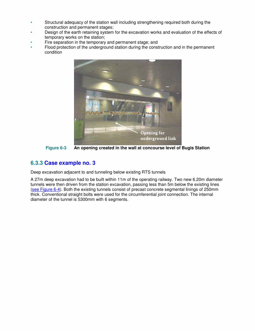
• Structural adequacy of the station wall including strengthening required both during the construction and permanent stages;
• Design of the earth retaining system for the excavation works and evaluation of the effects of temporary works on the station;
• Fire separation in the temporary and permanent stage; and • Flood protection of the underground station during the construction and in the permanent
condition
Figure 6-3 An opening created in the wall at concourse level of Bugis Station
6.3.3 Case example no. 3
Deep excavation adjacent to and tunneling below existing RTS tunnels
A 27m deep excavation had to be built within 11m of the operating railway. Two new 6.20m diameter tunnels were then driven from the station excavation, passing less than 5m below the existing lines (see Figure 6-4). Both the existing tunnels consist of precast concrete segmental linings of 250mm thick. Conventional straight bolts were used for the circumferential joint connection. The internal diameter of the tunnel is 5300mm with 6 segments.
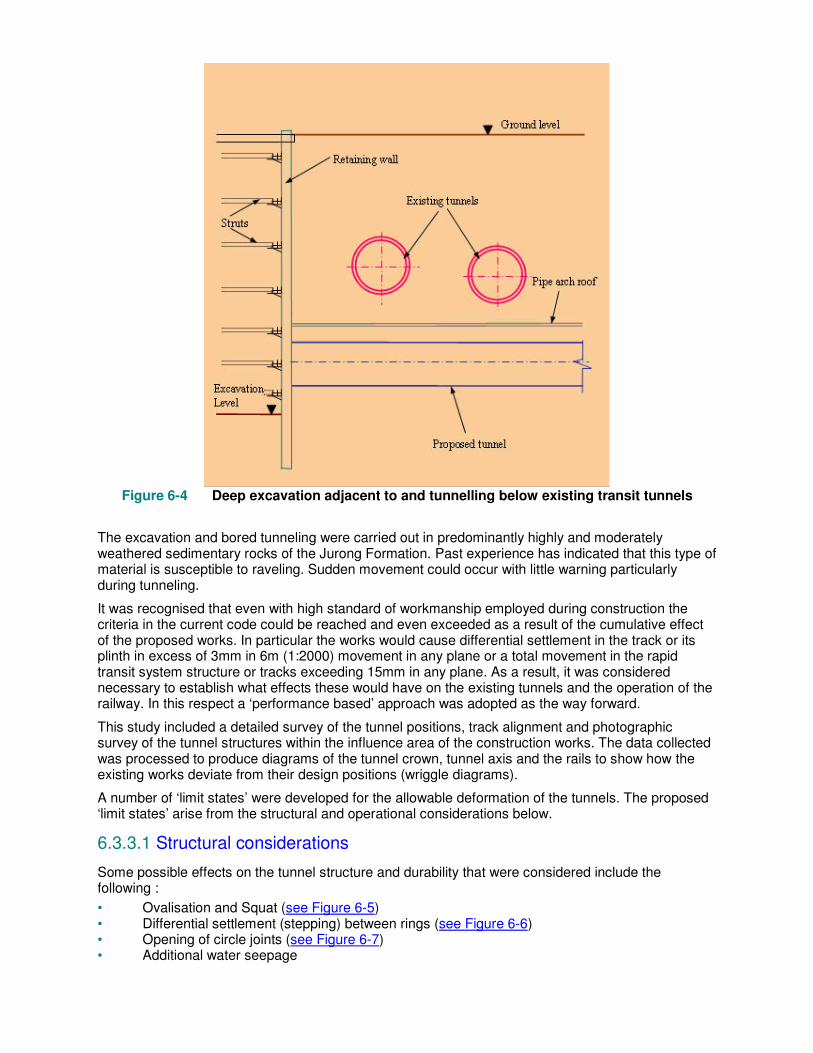
Figure 6-4 Deep excavation adjacent to and tunnelling below existing transit tunnels
The excavation and bored tunneling were carried out in predominantly highly and moderately weathered sedimentary rocks of the Jurong Formation. Past experience has indicated that this type of material is susceptible to raveling. Sudden movement could occur with little warning particularly during tunneling.
It was recognised that even with high standard of workmanship employed during construction the criteria in the current code could be reached and even exceeded as a result of the cumulative effect of the proposed works. In particular the works would cause differential settlement in the track or its plinth in excess of 3mm in 6m (1:2000) movement in any plane or a total movement in the rapid transit system structure or tracks exceeding 15mm in any plane. As a result, it was considered necessary to establish what effects these would have on the existing tunnels and the operation of the railway. In this respect a ‘performance based’ approach was adopted as the way forward.
This study included a detailed survey of the tunnel positions, track alignment and photographic survey of the tunnel structures within the influence area of the construction works. The data collected was processed to produce diagrams of the tunnel crown, tunnel axis and the rails to show how the existing works deviate from their design positions (wriggle diagrams).
A number of ‘limit states’ were developed for the allowable deformation of the tunnels. The proposed ‘limit states’ arise from the structural and operational considerations below.
6.3.3.1 Structural considerations
Some possible effects on the tunnel structure and durability that were considered include the following :
• Ovalisation and Squat (see Figure 6-5) • Differential settlement (stepping) between rings (see Figure 6-6) • Opening of circle joints (see Figure 6-7) • Additional water seepage

Figure 6-5 Tunnel ring deformation
Figure 6-6 Steps (settlement between rings) at tunnel joints
Figure 6-7 Opening of circle joint

6.3.3.2 Operational considerations
Some possible effects on the track due to tunnelling and excavation works that were considered include the following:
• Track geometry • Structure gauge clearance • Failure of track hold-down bolt
6.3.3.3 Enhanced monitoring
Having established all the limit states, it was then necessary to develop an observational monitoring procedure based on the measured movements within each limit state. The instrumentation of the tunnels and the track was enhanced such that elements such as track twist, opening up of circle joints, vertical distortion of the rails could be measured. The action plan was developed based on the critical levels of the components calculated with the necessary action to be taken in the event that they materialised.
To supplement the automatic trainway monitoring system, the instrumentation was enhanced with the following items:
• Manual survey to determine the track twist, dip and peak of the track every alternate day during the critical stage of work;
• Automatic tiltmeter, electro-level and settlement cell (see Figure 6-8) to monitor the change to the track twist;
• Measurement of opening of circle joints using a crack meter (see Figure 6-8) and steps or differential settlement between tunnel rings;
• Borehole extensometers to determine in-ground settlement.
The monitoring results were cabled back to the office computer so that monitoring could continue 24 hours a day.
Figure 6-8 Provision of total station, prisms, crack meter, settlement cells and vibration
sensor in the railway tunnel
Useful References:
1. The Novena Square. An office cum retail development over MRT station – Structural design and construction considerations (2000) by Tan Guan & Allan K J Teo, TY Lin South East Asia Pte Ltd
2. The Novena Square. An office cum retail development over MRT station (2000) by DP Architects
3. New HDB Centre at Toa Payoh – Integration with Toa Payoh MRT station by Lai Huen Poh, RSP Architects Planners & Engineers (Pte) Ltd

4. Planning the monitoring required to confirm the movement and rotation of tunnels and track work due to excavation and tunnelling by J.N.Shirlaw, S.K.Tham-Lee, F.K.Wong, L.P.Wong-Ang, D.C.Chen, N.Osborne, & C.G.Tan