hand-eye calibration without hand orientation measurement...
TRANSCRIPT

Hand-Eye Calibration without Hand OrientationMeasurement Using Minimal Solution
Zuzana Kukelova1 Jan Heller1 Tomas Pajdla2
1Center for Machine Perception, Department of CyberneticsFaculty of Elec. Eng., Czech Technical University in Prague
166 27 Prague 6, Technicka 2, Czech Republic2Neovision, s.r.o., Barrandova 409143 00 Prague 4, Czech Republic
Abstract. In this paper we solve the problem of estimating the relativepose between a robot’s gripper and a camera mounted rigidly on the grip-per in situations where the rotation of the gripper w.r.t. the robot globalcoordinate system is not known. It is a variation of the so called hand-eyecalibration problem. We formulate it as a problem of seven equations inseven unknowns and solve it using the Grobner basis method for solv-ing systems of polynomial equations. This enables us to calibrate fromthe minimal number of two relative movements and to provide the firstexact algebraic solution to the problem. Further, we describe a methodfor selecting the geometrically correct solution among the algebraicallycorrect ones computed by the solver. In contrast to the previous itera-tive methods, our solution works without any initial estimate and has noproblems with error accumulation. Finally, by evaluating our algorithmon both synthetic and real scene data we demonstrate that it is fast,noise resistant, and numerically stable.
1 Introduction
The problem of estimating the relative position and orientation of a robot grip-per and a camera mounted rigidly on the gripper, known as hand-eye calibra-tion problem, has been studied extensively in the past [23, 24, 17, 2, 25, 9]. Thisproblem arises in wide range of applications not only in robotics but also inautomotive or medical industries.
The standard formulation of this problem leads to solving a system of equa-tions of the form
AX = XB, (1)
where known A and B and unknown X are homogeneous transformation matricesof the form [
R t0> 1
], (2)
with 3× 3 rotation matrix R ∈ SO(3) and 3× 1 translation vector t ∈ R3. It hasbeen shown in [24] that at least two motions with non-parallel rotation axes are
2 Zuzana Kukelova, Jan Heller, Tomas Pajdla
B′i
B′i+1
Bi
X
XAi
A′i
A′i+1
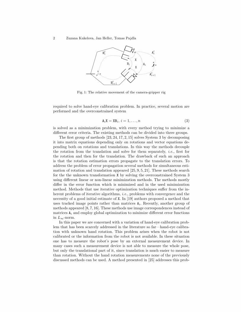
Fig. 1: The relative movement of the camera-gripper rig
required to solve hand-eye calibration problem. In practice, several motion areperformed and the overconstrained system
AiX = XBi, i = 1, . . . , n (3)
is solved as a minimization problem, with every method trying to minimize adifferent error criteria. The existing methods can be divided into three groups.
The first group of methods [23, 24, 17, 2, 15] solves System 3 by decomposingit into matrix equations depending only on rotations and vector equations de-pending both on rotations and translations. In this way the methods decouplethe rotation from the translation and solve for them separately, i.e., first forthe rotation and then for the translation. The drawback of such an approachis that the rotation estimation errors propagate to the translation errors. Toaddress the problem of error propagation several methods for simultaneous esti-mation of rotation and translation appeared [25, 9, 5, 21]. These methods searchfor the the unknown transformation X by solving the overconstrained System 3using different linear or non-linear minimization methods. The methods mostlydiffer in the error function which is minimized and in the used minimizationmethod. Methods that use iterative optimization techniques suffer from the in-herent problems of iterative algorithms, i.e., problems with convergence and thenecessity of a good initial estimate of X. In [19] authors proposed a method thatuses tracked image points rather than matrices Ai. Recently, another group ofmethods appeared [8, 7, 16]. These methods use image correspondences instead ofmatrices Ai and employ global optimization to minimize different error functionsin L∞-norm.
In this paper we are concerned with a variation of hand-eye calibration prob-lem that has been scarcely addressed in the literature so far—hand-eye calibra-tion with unknown hand rotation. This problem arises when the robot is notcalibrated or the information from the robot is not available. In these situationone has to measure the robot’s pose by an external measurement device. Inmany cases such a measurement device is not able to measure the whole pose,but only the translational part of it, since translation is much easier to measurethan rotation. Without the hand rotation measurements none of the previouslydiscussed methods can be used. A method presented in [25] addresses this prob-
Hand-Eye Calibration without Hand Orientation Using Minimal Solution 3
lem by nonlinear optimization and estimates simultaneously both rotational andtranslational parts. However, it requires a good initial estimate of X.
In case of two relative motions, we solve this problem by formulating it as asystem of seven equations in seven unknowns and solving it using the Grobnerbasis method for solving systems of polynomial equations. This provides an exactalgebraic solution and has none of the problems of the former numerical mini-mization methods, i.e., problems with convergence or the necessity of having agood initial estimate. In case of three of more motions, we use a residual func-tion to select an initial solution among the candidates provided by the Grobnerbasis method to initialize the method of [25]. By evaluating our solution onboth synthetic and real scene data, we demonstrate that it is efficient, fast, andnumerically stable. Further, we show that in case of more than two motions itprovides a good estimate for nonlinear optimization.
2 Problem Formulation
First, let us consider the classical hand-eye calibration problem. The goal is toestimate the relative pose, i.e., the rotation and the translation of the cameraw.r.t. the gripper, see Figure 1. We will describe this transformation by thehomogeneous transformation matrix
X =
[RX tX0> 1
], (4)
where RX ∈ SO(3) is the unknown rotation from the camera to the gripper andtX ∈ R3 the unknown translation.
Let us consider the ith pose of the robot and denote the transformationmatrix from the camera to the world coordinate system by A′i and the transfor-mation matrix from another coordinate system in the world—usually placed inthe robot’s base—to the robot’s gripper by B′i, see Figure 1. Camera’s transfor-mations A′i can be obtained using the well known absolute pose solvers [6, 14]and transformations B′i from the robot’s positioning software.
Figure 1 shows that by knowing two poses of the robot we can get X fromthe following equation
AiX = XBi, (5)
where Ai = A′−1i A′i+1 and Bi = B′i+1B
′−1i are homogeneous transformation matri-
ces representing the respective relative movements. Equation 5 can be decom-posed into a matrix and a vector equation
RAiRX = RXRBi , (6)RAitX + tA = RXtBi + tX. (7)
At least two motions with non-parallel rotation axes are required to solvethis system of equations. With two or more motions known, we obtain an over-constrained system of polynomial equations.

4 Zuzana Kukelova, Jan Heller, Tomas Pajdla
In situations where one does not have the information from the robot’s po-sitioning software or the robot is not precisely calibrated transformations B′i arenot readily known. To recover them, one has to use some external measurementequipment. In this paper we are interested in situations where such a measure-ment device does not allow to recover the whole pose of the robotic gripper, butonly its translational part.
Typically, the external measurement devices are able to recover absolute grip-per’s positions t′B w.r.t. robot’s base. However, in Equation 7 relative translationstB appear. In order to compute the relative translations tB there has to be at leastone position where the full pose of the robot can be recovered, i.e., where therotation R′B is known as well. Even for an uncalibrated robot, the robot’s homeposition can be used as such a priori known pose. By constructing the relativemovements in such a way as to always end in a position with a known rotationR′B, relative translations tB can be recovered. Since the positions with a prioriknown poses are usually hard to come by, it is advantageous for a method to beable to calibrate from a minimal number of movements possible.
3 Minimal Problem
First, let us suppose that we can measure two gripper’s relative translations tBi
and tBjand two respective relative camera motions Ai and Aj . Now, let us note
that the vector Equation 7 does not contain the unknown gripper’s rotations RBi .By parametrizing the rotation RX by the unit quaternion q = a+ bi+ cj + dk as
RX ≡ RqX =
a2 + b2 − c2 − d2 2bc− 2ad 2ac+ 2bd2ad+ 2bc a2 − b2 + c2 − d2 2cd− 2ab2bd− 2ac 2ab+ 2cd a2 − b2 − c2 + d2
(8)
and substituting it into the vector Equation 7 we get three polynomial equationsin seven unknowns, i.e., three translation parameters for tX and four rotationparameters a, b, c, and d. Now we can apply this substitution to the two motionsi and j and by adding the equation defining the unit quaternion q we obtain thefollowing system of equations:
Problem 1 (Minimal Hand-Eye Calibration)
Given RAi, RAj
, tAi, tAj
, tBi, tBj
find RX ∈ SO(3), tX ∈ R3
subject to RAitX + tAi
= RqXtBi
+ tX,
RAjtX + tAj
= RqXtBj
+ tX,
a2 + b2 + c2 + d2 = 1.

Hand-Eye Calibration without Hand Orientation Using Minimal Solution 5
Problem 1 is a well-constrained system of seven equations in seven unknowns.To solve it for the unknown hand-eye calibration X, the Grobner basis methodcan be readily used. This leads to a fast and non-iterative solution with no needfor an initial solution estimate. Note that the minimal number of two relativemovements without rotations RBi
and RBjis needed to construct the system.
In case rotations RBiand RBj
need to be recovered as well, by substitutingthe solutions for the rotation RX into the Equation 6 we get the rotations as
RBi= R−1
X RAiRX, (9)
RBj= R−1
X RAjRX. (10)
3.1 Grobner Basis Method
The Grobner basis method for solving systems of polynomial equations has re-cently became popular in computer vision and it has been used to create veryfast, efficient and numerically stable solvers to many difficult problems. Themethod is based on polynomial ideal theory and is concerned with special basesof these ideals called Grobner bases [3]. Grobner bases have the same solutionsas the initial system of polynomial equations defining the ideal but are often eas-ier to solve. Grobner bases are usually used to construct special multiplication(action) matrices [18], which can be viewed as a generalization of the companionmatrix used in solving one polynomial equation in one unknown. The solutionsto the system of polynomial equations is then obtained from the eigenvaluesand eigenvectors of such action matrices. See [3, 4] for more on Grobner basismethods and [20, 10, 1] for their applications in computer vision.
Since general algorithms [3] for computing Grobner basis are not very efficientfor solving problems which appear for example in computer vision, an automaticgenerator of specific polynomial equations solvers based on the Grobner basismethod has been proposed in [11]. These specific solvers often provide veryefficient solutions to a class of systems of polynomial equations consisting of thesame monomials and differing only in the coefficients.
Computer vision problems—like the hand-eye calibration problem presentedin this paper—share the convenient property that the monomials appearing inthe set of initial polynomials are always the same irrespective of the concretecoefficients arising from non-degenerate measurements. Therefore it is possibleto use efficient specific solvers instead of less efficient general algorithms [3] forconstructing the Grobner bases.
The process of creating the specific solvers consists of two phases. In the first“offline” phase, the so-called “elimination templates” are found. These tem-plates decide the elimination sequence in order to obtain all polynomials fromthe Grobner basis or at least all polynomials necessary for the construction ofthe action matrix. This phase is performed only once for a given problem. Inthe second “online” phase, the elimination templates are used with coefficientsarising from the specific measurements to construct the action matrix. Then,eigenvalues and eigenvectors of the action matrix provide solutions to the orig-inal polynomial equations. The automatic generator presented in [11] performs

6 Zuzana Kukelova, Jan Heller, Tomas Pajdla
the offline phase automatically and for an input system of polynomial equationsoutputs an efficient online solver.
3.2 Grobner Basis Solver
To create an efficient solver for Problem 1 we used the automatic generatorproposed in [11]. The Grobner basis solver of the proposed hand-eye calibrationproblem starts with seven equations in seven unknowns, i.e., three translationparameters for tX and four rotation parameters a, b, c, and d.
From the generator we obtained an elimination template which encodes howto multiply the seven input polynomials by the monomials and then how toeliminate the polynomias using the Gauss-Jordan (G-J) elimination process toobtain all polynomials necessary for the construction of the action matrix. Inour case the automatic generator created the action matrix Ma for multiplicationby a.
To get the elimination template the generator first generated all monomialmultiples of the initial seven polynomial equations up to the total degree of four.This resulted in 252 polynomials in 330 monomials. Then the generator removedall unnecessary polynomials and monomials, i.e., polynomials and monomialsthat do not influence the resulting action matrix. This resulted in matrix a182 × 203 Q representing the polynomials for the construction of the actionmatrix Ma, i.e., the elimination template.
The online solver then only performs one G-J elimination of matrix Q fromthe elimination template identified in the offline stage. This matrix containscoefficients which arise from specific measurements, i.e., rotations RAi
and RAj
and translations tAi,tAj
,tBi, and tBj
. After G-J elimination of matrix Q, actionmatrix Ma can be created from its rows. The solutions to all seven unknowns canbe found from the eigenvectors of the action matrix Ma. The online stage takesabout 1 ms to finish in case of Problem 1.
This gives us a set Xij of up to 16 real solutions of X. However each of thesesolutions appears twice, i.e., there are double roots. Therefore we have only up to8 different real solutions. Usually only one to four of them are geometrically fea-sible, i.e., are real and of a reasonable length of the translation. The correct onecan be chosen from the feasible solutions manually using some prior knowledgeabout the transformation X or automatically using an additional set of solu-tions for different relative movements. The next section describes an automaticprocedure for selecting the correct transformation.
4 Automatic Solution Selection
In order to automatically select the geometrically correct solution among thealgebraically correct ones in Xij , at least one more set of solutions to Problem 1for a different combination of relative movements is needed. Let Xk` be sucha set for two additional movements k and `. Supposing that the movementsi, j and k, ` form a geometrically non-degenerate configuration, we will find the

Hand-Eye Calibration without Hand Orientation Using Minimal Solution 7
geometrically correct solution as Xij ∩ Xk`. In the presence of noise however,the intersection Xij ∩Xk` will most likely be an empty set. In this case we haveto select a solution from the union Xij ∪ Xk` that best fits the equations ofProblem 1 for different motions. We will measure the fitness of a solution X bythe residual error of Equation 7
ei(X) = RAitX + tAi − RXtBi − tX. (11)
Now let us formalize the idea of selecting the best solution and to extend it tothe case of more that two solution sets. Let n be the number of available relativemovements and let I be a set of pairs of indexes of the relative movements
I ⊂ {{i, j} : i, j ≤ n} , |I| ≥ 2. (12)
Let X be a set of solutions to Problem 1 for the pairs from the index set I,
X =⋃{i,j}∈I
Xij . (13)
We select the geometrically correct solution among the solutions in X by solvingthe following problem:
Problem 2 (Minimal Hand-Eye Calibration for n Movements)
Given RAi, tAi
, tBi, I, i = 1, . . . , n
and a set of solutions X =⋃{i,j}∈I Xij
find X? = arg minX∈X∑n
i=1 ei(X)>ei(X)
As we can see from the above formulation, solving Problem 2 amounts to select-ing a minimum from a set of |X | real numbers.
In the presence of noise and in case n > 2, we can further refine the solutionby an optimization method. For our experiments, we chose the method of Zhuangand Shiu [25] which requires a good initial estimate X0. By setting X0 ≡ X?, wecan refine the solution by solving the following minimization problem:
Problem 3 (Zhuang [25])
Given RAi , tAi , tBi , i = 1, . . . , n
and an initial solution estimate X0
find X?opt = arg min
∑ni=1 ei(X)>ei(X)
subject to RX ∈ SO(3)
8 Zuzana Kukelova, Jan Heller, Tomas Pajdla
−20 −15 −10 −5 0 50
10
20
30
40
50
60
70
80
90
100
log10 angular error of RX
Fre
quen
cy
−20 −15 −10 −5 0 50
20
40
60
80
100
120
log10 relative error of tX
Fre
quen
cy
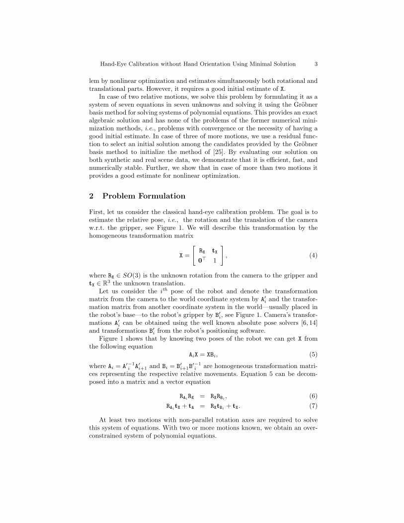
Fig. 2: log10 angular error of the estimated rotation RX (Left) and log10 translation errorof tX (Right) for noise free data.
5 Experiments
To experimentally validate the proposed solutions, we use both synthetically gen-erated and real word calibration scenarios. First, we use synthetically generatedground truth scenes to study the numerical stability of the proposed solution toProblem 1. Next, we study the behavior of the solutions to Problem 2 and Prob-lem 3 on synthetic scenes consisting of 4 non-degenerate poses. Finally, we showthe viability of the minimal solution in a real life experiment with a MitsubishiMELFA-RV-6S serial manipulator with four draw-wire encoders attached to itsend effector to recover the translations tBi .
In all of the experiments we scaled the lengths of the input translation vectorstBi
and tAiby the length of the largest one of them prior to running the Grobner
basis solver. We observe that this scaling improves the numerical stability of thesolution.
The experiments were run on a 3GHz Intel Core i7 based desk-top computer running 64-bit Linux. The Matlab implementationof the proposed method used in the experiments is available athttp://cmp.felk.cvut.cz/minimal/handeye.php.
5.1 Experiments with Synthetic Data
Numerical Stability Experiment. First, we studied the behavior of the pro-posed Grobner basis solver of Problem 1 to check its numerical stability. Wegenerated 1000 random scenes with 100 points Pk, k = 1, . . . , 100, evenly dis-tributed in the unit ball. Each scene consisted of 3 random absolute camera posesA′i. The cameras were positioned to (i) be facing the center of the scene, (ii) seethe scene points from the field of view (FOV) ranging from 40◦ to 80◦. For ev-ery scene ground truth transformation Xgt was generated so that the angle andthe axis of RXgt were random and uniformly distributed and that
∥∥tXgt∥∥ ≈ 0.1.
Hand-Eye Calibration without Hand Orientation Using Minimal Solution 9
0 0.05 0.1 0.15 0.2 0.25 0.3 0.35 0.4 0.45 0.50
0.05
0.1
0.15
0.2
0.25
0.3
0.35
σ of Gaussian noise in pij in degrees
Rel
ative
erro
roft X
MHECMHEC+ZHTSAIDAN
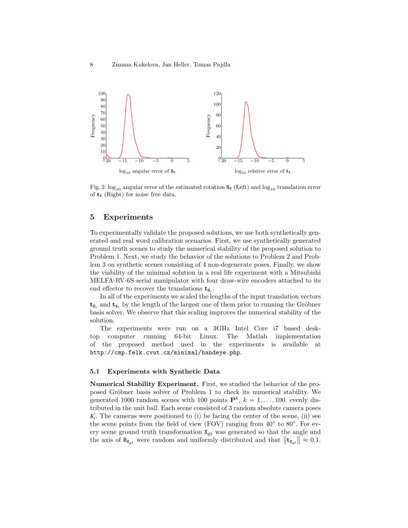
Fig. 3: Relative error of recovered translation tX for different levels of Gaussian noise.
Absolute robot poses B′i were determined by chaining X−1gt and the generated
absolute camera positions. For every combination of ground truth RXgt , tXgt andthe recovered RX, tX we measured the error of the rotation as the angle θ of therotation R>X RXgt , such that 0 ≤ θ ≤ π and the error of translation as the relativeerror
∥∥tX − tXgt∥∥ / ∥∥tXgt∥∥. Figure 2 shows the histograms of the respective errors,
certifying the numerical stability of the solver.
Calibration Experiment. In this experiment we analyzed the performancewith respect to image noise. We used the same scheme to generate random scenesas in Numerical Stability Experiment. This time, we generated four absoluterobot poses in each scene and recovered the absolute camera positions by P3Palgorithm [14].
We started by computing Pki —the positions of the 100 random points Pk
with respect to the coordinate systems of the cameras A′i, i = 1, . . . , 4. Further,we normalized Pk
i to get only the directional vectors pki that were progressively
corrupted with angular Gaussian noise. Finally, we used P3P in RANSAC loopto obtain noise corrupted absolute camera poses A′i, i = 1, . . . 4 .
We experimented with 11 levels of angular Gaussian noise with the standarddeviation σ ranging from 0 to 0.5 degrees, with the highest noise level translat-ing to σ of ca. 20–40 pixels for a 8MP camera with 40◦–80◦ field of view. Wegenerated and recovered camera poses for 1000 random scenes for every noiselevel.
We recovered hand-eye calibrations X by four different methods. The firstmethod MHEC identifies the results obtained by the Grobner basis solver withthe solution selected according to Problem 2. The second method MHEC+ZH

10 Zuzana Kukelova, Jan Heller, Tomas Pajdla
0 0.05 0.1 0.15 0.2 0.25 0.3 0.35 0.4 0.45 0.50
0.5
1
1.5
2
2.5
3
3.5
σ of Gaussian noise in pij in degrees
Angula
rer
ror
ofRX
indeg
rees MHEC
MHEC+ZHTSAIDAN
Fig. 4: Angular error of recovered rotation RX for different levels of Gaussian noise.
stands for the results obtained by the method [25] (Problem 3) when initializedby the results of MHEC. For completeness sake, we include results obtained bythe methods [24] labeled as TSAI and [5] labeled in the figures as DAN. Thesemethods are not the direct competitors, since they require known robot rotationsRB. However, they can be used to gauge the accuracy of the results obtained byMHEC and MHEC+ZH.
Figures 3, 4, and 5 show the statistics of the obtained solutions using theMatlab boxplot function depicting values 25% to 75% quantile as a box withhorizontal line at median. Figures 3 and 4 show the respective errors of tX andRX using the same measures as described in Numerical Stability Experiment.Figure 5 shows the mean distance between the points Pk
i transformed into thecoordinate system of the gripper using the ground truth hand-eye transformationand the same points transformed into the coordinate system of the gripper usingthe estimated X. Note that the points were generated into the unit ball, i.e.,considering the diameter of this ball to be one meter means that the errors inFigure 5 are in meters.
5.2 Real Scene Data Experiment
In order to acquire a real scene calibration data, four draw-wire encoders wereconnected to the gripper of a Mitsubishi MELFA-RV-6S serial manipulator. ACanon 350D digital SLR camera with a Sigma 8 mm lens (cca. 130◦ field ofview) was also attached to the gripper to form a hand-eye system.
The robot was instructed to move the gripper to (i) the home position withthe known rotation w.r.t. the robot base, (ii) the four positions (backward, for-

Hand-Eye Calibration without Hand Orientation Using Minimal Solution 11
0 0.05 0.1 0.15 0.2 0.25 0.3 0.35 0.4 0.45 0.50
0.02
0.04
0.06
0.08
σ of Gaussian noise in pij in degrees
Eucl
idea
ner
ror
w.r.t.
the
gripper
MHECMHEC+ZHTSAIDAN
Fig. 5: Euclidean error of recovered calibration X for different levels of Gaussian noise.
ward, left, right) distant approximately 400 mm at 10 degree pitch, (iii) the samefour positions at 20 degree pitch, (iv) the position approximately 250 mm underthe home position, and (v) the four positions at this height at 10 and 20 degreepitch again. While the robot was moving, the camera was remotely triggered toacquire 2,592×1,728 pixels large images of a circular view field with 1,040 pixelsradius.
The internal calibration of the camera in the form of a 2-parameter equi-angular model [12] was obtained using an image of a checkerboard with man-ually labeled corners. Then, a state-of-the-art sequential structure-from-motionpipeline [22] was used to automatically generate MSER, SIFT, and SURF featurepoints, perform approximate nearest neighbor matching in the descriptor space,verify the matches by pairwise epipolar geometries estimated by the 5-point al-gorithm [13] in a RANSAC loop, and create tracks and triangulated 3D pointsfrom verified matches spanning several images. The reconstructed 3D model wasscaled to millimeter units by knowing the real dimensions of the checkerboardand measuring the distance of the corresponding 3D points in the model.
We used the system of four draw-wire encoders to determine the absolutepositions of the gripper w.r.t. the robot base. For the experiment we chose 2motions ending in the robots home position. Since the rotation of the robot inthe home position is known, it is possible to transform the positions providedby the draw-wire encoders into the home position coordinate system and obtaintranslations tB1 and tB2 . We used tB1 and tB2 in combination with A1, A2 obtainedfrom structure-from-motion to compute the hand-eye transformation X and therelative gripper rotations RB1 and RB2 .

12 Zuzana Kukelova, Jan Heller, Tomas Pajdla
(a) (b)
(c) (d)
Fig. 6: Real data experiment. (a) A Mitsubishi MELFA-RV 6S serial manupulator usedto acquire the data for the experiment. (b) The 3D model obtained from SfM. (c)Sample images of our scene taken by the camera mounted on the gripper of the robot.(d) Close up of the camera-gripper rig with draw-wire encoders.
For comparison, we also used tBgt2 and tBgt2 from robots positioning softwarewith the same camera motions A1 and A2 to compute hand-eye transformationX, RB1 , and RB2 .
Since the robot was calibrated, we can also compare the computed gripperrotations RB1 , RB2 , RB1 , and RB2 with the rotations RBgt1 and RBgt2 from the robotspositioning software, see Table 1.
Table 1: Angular rotation errors of estimated gripper rotations in degrees.
RB1 RB2 RB1 RB2
RBgt1 0.84 — 0.89 —
RBgt2 — 0.61 — 1.09
Finally, let us express the obtained translations from the gripper to thecamera center using the translation from the draw-wire encoders −R>X tX =(110.2, 26.2, 47.9), and using the translation from the robot, −R>X tX =(126.5, 28.7, 51.1).

Hand-Eye Calibration without Hand Orientation Using Minimal Solution 13
These result are consistent with each other as well as with the rough physicalmeasurement of the mechanical reduction and show the validity of the obtainedresults.
6 Conclusion
We presented the first minimal problem of hand-eye calibration for the situationswhere the gripper’s rotations are not known. We formulated the problem as asystem of seven equations in seven unknowns and solved it using the Grobnerbasis method for solving systems of polynomial equations providing the firstexact algebraic solution to the problem. This solution uses the minimal numberof two relative movements. Further, we showed how to select the geometricallycorrect solution using additional relative movements. Finally, our experimentsshowed that the proposed solver is numerically stable, fast and—since it canhandle noisy inputs—that its results can be successfully used as initialization ofsubsequent minimization methods.
Acknowledgment
The authors were supported by the EC under projects FP7-SME-2011-285839De-Montes and FP7-288553 CloPeMa and by Grant Agency of the CTU Pragueproject SGS12/191/OHK3/3T/13. The authors would also like to thank MichalHavlena and Martin Meloun for their help with the real-data experiment.
References
1. Martin Bujnak, Zuzana Kukelova, and Tomas Pajdla. A general solution to theP4P problem for camera with unknown focal length. In IEEE Conference onComputer Vision and Pattern Recognition, pages 1–8, 2008.
2. Jack C. K. Chou and M. Kamel. Finding the position and orientation of a sensor ona robot manipulator using quaternions. International Journal of Robotics Research,10(3):240–254, 1991.
3. D.A. Cox, J.B. Little, and D. O’Shea. Using Algebraic Geometry. Graduate Textsin Mathematics. Springer, 2005.
4. D.A. Cox, J.B. Little, and D. O’Shea. Ideals, Varieties, And Algorithms: An Intro-duction to Computational Algebraic Geometry And Commutative Algebra. Numberv. 10 in Undergraduate Texts in Mathematics. Springer, 2007.
5. Konstantinos Daniilidis. Hand-eye calibration using dual quaternions. Interna-tional Journal of Robotics Research, 18:286–298, 1998.
6. M. Fischler and R. Bolles. Random sample consensus: A paradigm for model fittingwith applications to image analysis and automated cartography. Communicationsof the ACM, 24(6):381–395, 1981.
7. Jan Heller, Michal Havlena, and Tomas Pajdla. A branch-and-bound algorithm forglobally optimal hand-eye calibration. In IEEE Conference on Computer Visionand Pattern Recognition, 2012.

14 Zuzana Kukelova, Jan Heller, Tomas Pajdla
8. Jan Heller, Michal Havlena, Akihiro Sugimoto, and Tomas Pajdla. Structure-from-motion based hand-eye calibration using l∞ minimization. In IEEE Conference onComputer Vision and Pattern Recognition, pages 3497–3503, 2011.
9. Radu Horaud and Fadi Dornaika. Hand-eye calibration. The International Journalof Robotics Research, 14(3):195–210, 1995.
10. Zuzana Kukelova and Tomas Pajdla. A minimal solution to the autocalibration ofradial distortion. In IEEE Conference on Computer Vision and Pattern Recogni-tion, 2007.
11. Zuzana Kukelova, Martin Bujnak, and Tomas Pajdla. Automatic generator ofminimal problem solvers. In Proceedings of European Conference on ComputerVision, pages 302–315, Berlin, Heidelberg, 2008.
12. Branislav Micusik and Tomas Pajdla. Structure from motion with wide circu-lar field of view cameras. IEEE Transactions on Pattern Analysis and MachineIntelligence, 2006.
13. D. Nister. An efficient solution to the five-point relative pose problem. EEETransactions on Pattern Analysis and Machine Intelligence, 26(6):756–770, 2004.
14. David Nister and Henrik Stewenius. A minimal solution to the generalised 3-pointpose problem. Journal of Mathematical Imaging and Vision, 27(1):67–79, 2007.
15. F.C. Park and B.J. Martin. Robot sensor calibration: solving AX=XB on theeuclidean group. IEEE Transactions on Robotics and Automation, 10(5):717–721,1994.
16. Thomas Ruland, Tomas Pajdla, and Lars Kruger. Globally optimal hand-eye cali-bration. In IEEE Conference on Computer Vision and Pattern Recognition, 2012.
17. Y.C. Shiu and S. Ahmad. Calibration of wrist-mounted robotic sensors by solvinghomogeneous transform equations of the form AX=XB. IEEE Transactions onRobotics and Automation, 5(1):16–29, 1989.
18. Hans J. Stetter. Numerical polynomial algebra. SIAM, 2004.19. H. Stewenius, K. Astrom. Hand-eye calibration using multilinear constraints. In
Proceedings of the Asian Conference on Computer Vision, 2004.20. H. Stewenius, F. Schaffalitzky, and D. Nister. How hard is 3-view triangulation re-
ally? In IEEE Conference on Computer Vision and Pattern Recognition, volume 1,pages 686–693, 2005.
21. K. H. Strobl and G. Hirzinger. Optimal Hand-Eye Calibration. In IEEE/RSJ Inter-national Conference on Intelligent Robots and Systems, pages 4647–4653, Beijing,China, 2006.
22. Akihiko Torii, Michal Havlena, and Tomas Pajdla. Omnidirectional image stabi-lization for visual object recognition. International Journal of Computer Vision,91(2):157–174, 2011.
23. R.Y. Tsai and R.K. Lenz. Real time versatile robotics hand/eye calibration using3D machine vision. In IEEE International Conference on Robotics and Automation,pages 554–561 vol.1, 1988.
24. R.Y. Tsai and R.K. Lenz. A new technique for fully autonomous and efficient 3Drobotics hand/eye calibration. IEEE Transactions on Robotics and Automation,5(3):345–358, 1989.
25. Hanqi Zhuang and Yiu Cheung Shiu. A noise tolerant algorithm for wrist-mounted robotic sensor calibration with or without sensor orientation measure-ment. IEEE/RSJ International Conference on Intelligent Robots and Systems,volume 2, pages 1095–1100, 1992.