halfen anchor bolt systems · 2019-03-26 · hb-vmz injection system electroplated — for cracked...
TRANSCRIPT
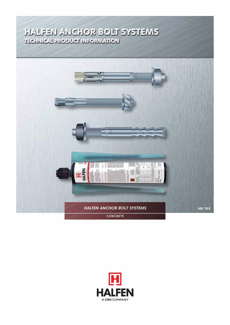
HALFEN ANCHOR BOLT SYSTEMS
CONCRETE
HB 19-E

2 © 2019 HALFEN · HB 19 - E ⋅ www.halfen.com
Contents
HALFEN ANCHOR BOLT SYSTEMS
1 Overview 3
2 HALFEN Chemical anchor bolt systems 4
- HB-VMZ Injection system, electroplated 5
- HB-VMZ Injection system, A4 8
- HB-V Injection system, electroplated/hot-dip galvanized/A4 12
- HB-VMU plus Injection system, electroplated 16
- HB-VMU plus Injection system, A4 19
- HB-VMU plus Injection system, electroplated/A4 for masonry 22
- Accessories 43
3 HALFEN Mechanical anchor systems 29
- HB-BZ Steel, electroplated 30
- HB-BZ A4 Stainless steel 33
- HB-BZ HCR Stainless steel 36
- HB-B Steel, electroplated 37
- HB-B A4 Stainless steel 40
- Accessories 43
4 Service 44
- Calculation software 45
- Design values, fire exposure 46
- Contacts 47
Singapore Power Transmission Cable Tunnel Project — HB-BZ

3
Overview
All Systems with (ETA)and CE marking
Non-cracked concrete
Cracked concrete Masonry
Fire protection
Finish
PageGV FV A4 HCR
Chemical anchor systems
HB-VMZ Injection system
5
HB-V Chemical anchor
12
HB-VMU plus Injection system
16
Mechanical anchor systems
HB-BZ Wedge anchor
30
HB-B Wedge anchor
37
© 2019 HALFEN · HB 19 - E · www.halfen.com
Overview
HALFEN ANCHOR BOLT SYSTEMS
The HALFEN Quality Management System meetsthe requirements of ISO 9001:2015. www.halfen.com ►► Downloads ►► Software/CAD
Easy-to-use and free calculation software available
Fire protection according to DIN 4102-2,Fire resistant classification F30, F60, F90 and F120
GV = electroplatedFV = hot-dip galvanized
A4 = A4 Stainless steelOn request HCR = Stainless steel HCR, 1.4529
1
5
2
4
3
Seismic loads
suitable for seismic loading
STAINLESS STEEL
www.dnvgl.com

4 © 2019 HALFEN · HB 19 - E ⋅ www.halfen.com
Chemical Anchor Bolt SystemsHALFEN ANCHOR BOLTS
HALFEN Anchor systems are an extensive range of top quality,
state-of-the-art fi xings for a wide range of applications. Competent, expert support is available for all systems and projects.
HB -VMZ Injection systemThe strongest and most versatile of anchors, can be used for various anchorage depths. These anchorsare suitable for heavy loads, evenfor minimal edge distances.Suitable for use in cracked andnon-cracked concrete.See page 5
HB -VMU plusCan be used in cracked, non-cracked concrete, solid masonryand in perforated brick masonry.This versatile system is reliable and easy to use. A threaded rod is usedas an eff ective anchorage element.See page 16
Service
Our Customer Service andTechnical Field Support Teamsare available to provide com-prehensive support for specifi c applications or to providesolutions for complete projects.
Design software Page 45
HB -V Chemical bolt anchorThe classic chemical anchor provides a cost effective, easy to install solu-tion for simple fixings in non-cracked concrete.See page 12
HALFEN ContactsPage 47
www.dnvgl.com
NOTES REGARDING THIS CATALOGUETechnical and design changes reserved. The information in this publication is based on state-of-the-art technology at the time of publication. We reserve the right to make technical and design changes at any time. HALFEN GmbH shall not accept liability for the accuracy of the information in this publication or for any printing errors.
The HALFEN GmbH subsidiaries in Germany, France, the Netherlands, Austria, Poland, Switzerland and the Czech Republic are Quality Management certified according to ISO 9001:2015, Certificate no. 202384-2016-AQ-GER-DAkkS.
Austria HALFEN Gesellschaft m.b.H.Leonard-Bernstein-Str. 101220 Wien
Phone: +43 - 1 - 259 6770 E-Mail: [email protected]: www.halfen.at
Belgium / Luxembourg HALFEN N.V.Borkelstraat 1312900 Schoten
Phone: +32 - 3 - 658 07 20E-Mail: [email protected]: www.halfen.be
Fax: +32 - 3 - 658 15 33
China HALFEN Construction Accessories Distribution Co.Ltd.Room 601 Tower D, Vantone CentreNo. A6 Chao Yang Men Wai StreetChaoyang District Beijing · P.R. China 100020
Phone: +86 - 10 5907 3200E-Mail: [email protected]: www.halfen.cn
Fax: +86 - 10 5907 3218
Czech Republic HALFEN s.r.o.Business Center ŠafránkovaŠafránkova 1238/1155 00 Praha 5
Phone: +420 - 311 - 690 060E-Mail: [email protected]: www.halfen.cz
Fax: +420 - 235 - 314 308
France HALFEN S.A.S.18, rue Goubet75019 Paris
Phone: +33 - 1 - 445231 00E-Mail: [email protected]: www.halfen.fr
Fax: +33 - 1 - 445231 52
Germany HALFEN Vertriebsgesellschaft mbHLiebigstr. 14 40764 Langenfeld
Phone: +49 - 2173 - 970 - 0E-Mail: [email protected]: www.halfen.de
Fax: +49 - 2173 - 970 225
Italy HALFEN S.r.l. Soc. UnipersonaleVia F.lli Bronzetti N° 2824124 Bergamo
Phone: +39 - 035 - 0760711E-Mail: [email protected]: www.halfen.it
Fax: +39 - 035 - 0760799
Netherlands HALFEN b.v.Oostermaat 37623 CS Borne
Phone: +31 - 74-267 14 49E-Mail: [email protected]: www.halfen.nl
Fax: +31 - 74-267 26 59
Norway HALFEN ASPostboks 20804095 Stavanger
Phone: +47 - 51 82 34 00E-Mail: [email protected]: www.halfen.no
Poland HALFEN Sp. z o.o.Ul. Obornicka 28760-691 Poznan
Phone: +48 - 61 - 622 14 14E-Mail: [email protected]: www.halfen.pl
Fax: +48 - 61 - 622 14 15
Spain HALFEN IBERICA, S.L.Polígono Industrial Santa Ana c/ Ignacio Zuloaga 2028522 Rivas-Vaciamadrid
Phone: +34 - 91 632 18 40E-Mail: [email protected]: www.halfen.es
Fax: +34 - 91 633 42 57
Sweden Halfen ABVädursgatan 5412 50 Göteborg
Phone: +46 - 31 - 98 58 00E-Mail: [email protected]: www.halfen.se
Fax: +46 - 31 - 98 58 01
Switzerland HALFEN Swiss AGHertistrasse 25 8304 Wallisellen
Phone: +41 - 44 - 849 78 78E-Mail: [email protected]: www.halfen.ch
Fax: +41 - 44 - 849 78 79
United Kingdom /Ireland
HALFEN Ltd.A1/A2 Portland CloseHoughton Regis LU5 5AW
Phone: +44 - 1582 - 47 03 00E-Mail: [email protected]: www.halfen.co.uk
Fax: +44 - 1582 - 47 03 04
United States of America HALFEN USA Inc. PO Box 18687 San Antonio TX 78218
Phone: +1 800.423.91 40E-Mail: [email protected]: www.halfenusa.com
Fax: +1 877.683.4910
For countries not listed HALFEN International
HALFEN International GmbHLiebigstr. 14 40764 Langenfeld / Germany
Phone: +49 - 2173 - 970 - 0 E-Mail: [email protected]: www.halfen.com
Fax: +49 - 2173 - 970 - 849
CONTACT HALFEN WORLDWIDE
HALFEN is represented by subsidiaries in the following countries, please contact us!

5
Processing and curing times
Temperature (°C) in the drill hole ≥ -5°C > -5°C ≥ 0°C ≥ +5°C ≥ +10°C ≥ +20°C ≥ +30°C ≥ +35°C ≥ +40°C
Processing time in hh:mm 01:20 00:45 00:20 00:12 00:06 00:04 00:02 84 sec. 84 sec.
Curing time in hh:mm
Dry concrete 06:00 06:00 03:00 02:00 01:20 00:45 00:25 00:20 00:15
Wet concrete 12:00 12:00 06:00 04:00 02:40 01:30 00:50 00:40 00:30
© 2019 HALFEN · HB 19 - E · www.halfen.com
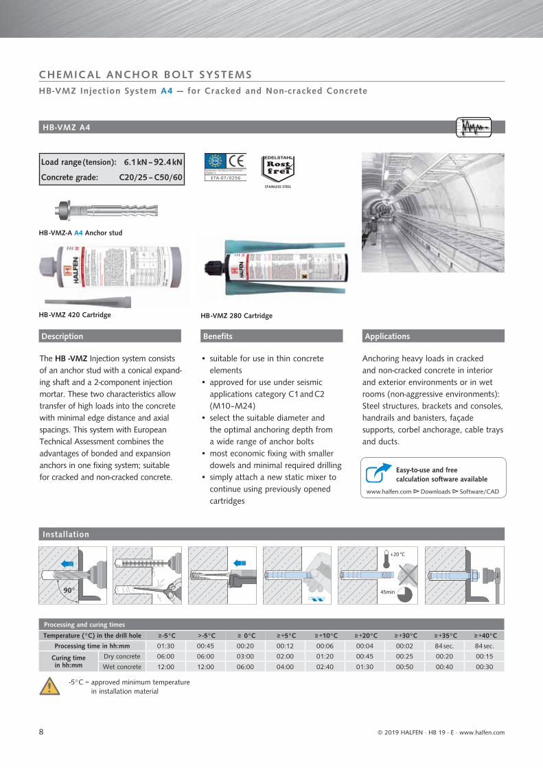
HB-VMZ Injection System Electroplated — for Cracked and Non-cracked Concrete
CHEMICAL ANCHOR BOLT SYSTEMS
The HB-VMZ Injection system consistsof an anchor rod with a conical expand-ing shaft and a 2-component injection mortar. These two characteristics allowtransfer of high loads with minimal edge distance and axial spacings in thin concrete components. This system with European Technical Assessment combines theadvantages of bonded and expansion anchors in one fixing system; suitable for cracked and non-cracked concrete.
HB -VMZ 280 Cartridge
HB -VMZ-A Anchor stud electroplated
HB-VMZ electroplated
Anchoring heavy loads in cracked and non-cracked concrete in dry interiorenvironments: steel structures, brackets and consoles, handrails and banisters, framing structures, cable trays and ducts.
Option 1
ETA -07/0256
European Technical Assessment -
www.halfen.com ►► Downloads ►► Software/CAD
Easy-to-use and free calculation software available
ApplicationsBenefitsDescription
Installation
Load range (tension): 6.1 kN – 105.7 kN
Concrete grade: C20/25 – C50/60
-5°C = approved minimum temperature in installation material
HB -VMZ 280 CartridgeHB -VMZ 420 Cartridge
• suitable for use in thin concreteelements
• approved for use under seismicapplications category C1 and C2(M8–M24)
• select the suitable diameter andthe optimal anchoring depth froma wide range of anchor bolts
• most economic fixing methodwith smaller dowels and minimal required drilling
• simply attach a new static mixer to continue using previously opened cartridges
HHHHB HBHB HBHBHBHBHB HBHB HBHBHBHBHHBHB HHBHBHBHBHBBHBHHHBHB HBHBHHHHBHBHHHBHB HBHHHHBHHHBHBHBHBHBHBBHBHHBHBBHBHBHBHBHBHBHHHHBBHBHBHBBBHBHHB HBHBHBHBHHBBBHBBHBHBHBHB BHBHBBHBBHBBHB-VM-VM-VM-VM-VMVVM-VVVVMMMMMMMMMMMMMMMMMMM-VMVM-V-VV-VMVVVVMMMMMMMMMMMMMM-V-VM-VM-VM-VM-VM-VM-VM-VVMVMMMMMMMMMMMMM-V-VM-VM-VM-VV-VM-VVV-VVMVMVMMMVMMVM-V-VV-VVV-VMMMMMMMMMM-VVM-VMMMMMMMMMMMVVMMMMMMM-V-VMMMMMMVMMMM-V-VVM-VMMMMM-V-VMMMMM-VVVMVVMM-VVVMMMVVVMMM-VMMV-VMMMMVMMMMMMMVVMMMVVMVMVMMMMVMVMVVMVMMMMMMVVVMMZ 2Z 2Z 2Z 2ZZ 2 22ZZZ 2280888880080000888008080088800088800000880000808880080888000880080800080008888800080800008000 8800088008880000 00000880800 00 088880 0 CararCarCarCarCararCarCaCarCarrrCararCarCararararCaraarCarCararCarCarCCCCarCarCarrCarCaCCarCararararrCCarCarCarCarCarCarCarCCarCCarCaCCaCarCarCarCCCCCCarrCCC tritttttttttttttttttrit ittt it iitttt itt iitt iitttt ittrit ittt iriitttt it it idgegegegegegegegggegegegegeegegeggeggegeggeggegegegegeggegegegeddgegegeedgdgegeggeegeeeedgdggeegegggedd edddggeggegegegeddddgeeddggedd eddgddgegddddgedgdddddggggedgedgddggddddddgggggg
45min
+20 °C
Nm
90°

6
Installation torque
Anchorage depth Tinst [Nm]
M8 50 10
M10 60 15
M12
7025
80
100 30
M1690
50125
M20 170 80
M24 225 120
Installation specifications
Anchor stud[mm] M8 M10 M12 M12 M12 M16 M16 M20 M24
Anchorage depth hef 50 60 70 80 100 90 125 170 225
Drill hole diameter do 10 12 14 14 14 18 18 24 26
Pre-positioned-setting df 9 12 14 14 14 18 18 24 (22) 26
Push-through-setting df - 14 16 16 16 20 20 26 28
Drill hole depth ho 55 65 75 85 105 98 133 180 240
Spanner/wrench size SW 13 17 19 19 19 24 24 30 36
Value in brackets for type LG (thread to the concrete surface)The clearance hole in the fixture must be completely grouted.
Spacing and edge distances
Anchor stud [mm] M8 M10 M10 M12 M12 M12 M16 M16 M20 M24
Effective anchorage depth hef 50 60 70 80 100 125 90 125 170 225
Minimum thickness of building component hmin 80 100 110 110 130 160 130 170/160 230/220 300/290cracked concrete
Minimum axial spacing smin 40 40 55 40 50 50 50 60 80 80Minimum edge distance cmin 40 40 55 50 50 50 50 60 80 80
non-cracked concreteMinimum axial spacing smin 40 50 55 55 80 80 50 60 80 105
Minimum edge distance cmin 40 50 55 55 55 55 50 60 80 105
After drilling the hole for the anchor,check the reverse side of the concrete element for damage (through penetration).Damage caused by penetrating the concrete must be repaired using high-strength mortar.Any mortar loss must be compensated for to ensure full anchorage depth hef is maintained.
For edge spacing c > 80 mm, axial spacing smin = 55 mm
© 2019 HALFEN · HB 19 - E · www.halfen.com
HB-VMZ Injection System Electroplated — for Cracked and Non-cracked Concrete
CHEMICAL ANCHOR BOLT SYSTEMS
Installation parameters
Dimensions in mm
Ordering example
HB -VMZ-A 50 8 ‒ 30/95 GV
HALFEN Anchor type
Anchoring depth
Diameter / thread [mm]Max. fixture thickness / total length [mm]
Finish
Tinst
d0
hef
≥ hmintfi x
s
cc
h
s
h0
df
7
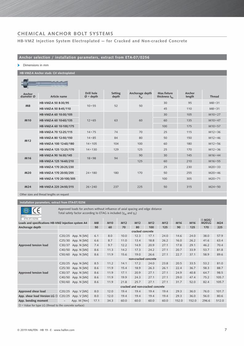
HB -VMZ-A Anchor studs GV electroplated
Anchor diameter Ø
Drill holeØ × depth
Settingdepth
Anchorage depth hef
Max.fixturethickness tfix
Anchorlength ThreadArticle name
M8HB -VMZ-A 50 8-30/95
10 × 55 52 5030 95 M8 × 31
HB -VMZ-A 50 8-45/110 45 110 M8 × 31
M10
HB -VMZ-A 60 10-30/105
12 × 65 63 60
30 105 M10 × 27
HB -VMZ-A 60 10-60/135 60 135 M10 × 47
HB -VMZ-A 60 10-100/175 100 175 M10 × 57
M12
HB -VMZ-A 70 12-25/115 14 × 75 74 70 25 115 M12 × 36
HB -VMZ-A 80 12-50/150 14 × 85 84 80 50 150 M12 × 46
HB -VMZ-A 100 12-60/180 14 × 105 104 100 60 180 M12 × 56
HB -VMZ-A 125 12-25/170 14 × 130 129 125 25 170 M12 × 36
M16HB -VMZ-A 90 16-30/145
18 × 98 9490 30 145 M16 × 44
HB -VMZ-A 125 16-60/210 125 60 210 M16 × 55
M20
HB -VMZ-A 170 20-25/230
24 × 180 180 170
25 230 M20 × 33
HB -VMZ-A 170 20-50/255 50 255 M20 × 46
HB -VMZ-A 170 20-100/305 100 305 M20 × 71
M24 HB -VMZ-A 225 24-50/315 26 × 240 237 225 50 315 M24 × 50
Other sizes and thread lengths on request
Installation parameters, extract from ETA-07/0256
Approved loads for anchors without influence of axial spacing and edge distanceTotal safety factor according to ETAG is included (γM and γF)
Loads and specifications HB -VMZ Injection system A4 M8 M10 M12 M12 M12 M12 M16 M16M20/M20 LG M24
Anchorage depth 50 60 70 80 100 125 90 125 170 225cracked concrete
Approved tension load
C20/25 App. N [kN] 6.1 8.0 10.0 12.3 17.1 24.0 14.6 24.0 38.0 57.9
C25/30 App. N [kN] 6.6 8.7 11.0 13.4 18.8 26.2 16.0 26.2 41.6 63.4
C30/37 App. N [kN] 7.4 9.7 12.2 14.9 20.9 27.1 17.8 29.1 46.2 70.4
C40/50 App. N [kN] 8.6 11.3 14.2 17.3 24.2 27.1 20.7 33.9 53.7 81.8
C50/60 App. N [kN] 8.6 11.9 15.6 19.0 26.6 27.1 22.7 37.1 58.9 89.6non-cracked concrete
Approved tension load
C20/25 App. N [kN] 8.5 11.2 14.1 17.2 24.0 23.8 20.5 33.5 53.2 81.0
C25/30 App. N [kN] 8.6 11.9 15.4 18.9 26.3 26.1 22.4 36.7 58.3 88.7
C30/37 App. N [kN] 8.6 11.9 17.1 20.9 27.1 27.1 24.9 40.8 64.7 98.5
C40/50 App. N [kN] 8.6 11.9 19.9 24.3 27.1 27.1 29.0 47.4 75.2 105.7
C50/60 App. N [kN] 8.6 11.9 21.8 25.7 27.1 27.1 31.7 52.0 82.4 105.7
cracked and non-cracked concrete
Approved shear load C20/25 App. V [kN] 8.0 12.0 19.4 19.4 19.4 19.4 29.3 36.0 76.0 101.7
App. shear load Version LG C20/25 App. V [kN] 8.0 12.0 19.4 19.4 19.4 19.4 29.3 36.0 56.0 80.6
App. bending moment – App. M [Nm] 17.1 34.3 60.0 60.0 60.0 60.0 152.0 152.0 296.6 512.0
= Value for type LG (thread to the concrete surface)
Option 1
ETA -07/0256
European Technical Assessment -
© 2019 HALFEN · HB 19 - E · www.halfen.com
CHEMICAL ANCHOR BOLT SYSTEMSHB-VMZ Injection System Electroplated — for Cracked and Non-cracked Concrete
Anchor selection / installation parameters, extract from ETA-07/0256
Dimensions in mm
8
Processing and curing times
Temperature (°C) in the drill hole ≥ -5°C > -5°C ≥ 0°C ≥ +5°C ≥ +10°C ≥ +20°C ≥ +30°C ≥ +35°C ≥ +40°C
Processing time in hh:mm 01:30 00:45 00:20 00:12 00:06 00:04 00:02 84 sec. 84 sec.
Curing time in hh:mm
Dry concrete 06:00 06:00 03:00 02:00 01:20 00:45 00:25 00:20 00:15
Wet concrete 12:00 12:00 06:00 04:00 02:40 01:30 00:50 00:40 00:30
© 2019 HALFEN · HB 19 - E ⋅ www.halfen.com
CHEMICAL ANCHOR BOLT SYSTEMSHB-VMZ Injection System A4 — for Cracked and Non-cracked Concrete
HB -VMZ 280 CartridgeHB -VMZ 420 Cartridge
HB -VMZ-A A4 Anchor stud
www.halfen.com ►► Downloads ►► Software/CAD
Easy-to-use and free calculation software available
Benefits ApplicationsDescription
Load range (tension): 6.1 kN – 92.4 kN
Concrete grade: C20/25 – C50/60
HB-VMZ A4
Installation
-5°C = approved minimum temperature in installation material
Anchoring heavy loads in cracked and non-cracked concrete in interior and exterior environments or in wet rooms (non-aggressive environments): Steel structures, brackets and consoles, handrails and banisters, façadesupports, corbel anchorage, cable trays and ducts.
The HB -VMZ Injection system consistsof an anchor stud with a conical expand-ing shaft and a 2-component injectionmortar. These two characteristics allow transfer of high loads into the concrete with minimal edge distance and axialspacings. This system with EuropeanTechnical Assessment combines theadvantages of bonded and expansion anchors in one fixing system; suitablefor cracked and non-cracked concrete.
• suitable for use in thin concreteelements
• approved for use under seismicapplications category C1 and C2(M10–M24)
• select the suitable diameter andthe optimal anchoring depth froma wide range of anchor bolts
• most economic fixing with smaller dowels and minimal required drilling
• simply attach a new static mixer to continue using previously opened cartridges
STAINLESS STEEL
Option 1
ETA -07/0256
European Technical Assessment -
45min
+20 °C
Nm
90°

9
Value in brackets for type LG (with thread to the concrete surface)The clearance hole in the fixture must be completely grouted.
Installation specifications
Anchor stud M20/M20 LGM8 M10 M10 M12 M12 M12 M16 M16 M20 M24
Anchorage depth hef 50 60 75 80 100 125 105 125 115 170 200
Drill hole diameter do 10 12 12 14 14 14 18 18 22 24 26
Pre-positioned-setting df 9 12 12 14 14 14 18 18 22 24 (22) 26
Push-through-setting df - 14 14 16 16 16 20 20 26 26 28
Drill hole depth ho 55 65 80 85 105 130 113 133 120 180 215
Spanner/wrench size SW 13 17 17 19 19 19 24 24 30 30 36
Installation torque
Anchoring depth Tinst [Nm]
M8 50 10
M1060
1575
M12
80 25
10030
125
M16105
50125
M20 11580M20/
M20 LG 170
M24 200 120
Spacing and edge distances
Anchor stud M20/20 LGM8 M10 M10 M12 M12 M12 M16 M16 M20 M24
Effective anchorage depth hef 50 60 75 80 100 125 105 125 115 170 200
Min. building component thickness hmin 80 100 110/100 110 130 160 150 170/160 160 230/220 270/260
cracked concreteMin. axial spacing smin 40 40 40 40 50 50 50 60 80 80 80Min. edge distance cmin 40 40 40 50 50 50 50 60 80 80 80
non-cracked concreteMin. axial spacing smin 40 50 50 55 80 80 60 60 80 80 105
Min. edge distance cmin 40 50 50 55 55 55 60 60 80 80 105
After drilling the hole for the anchor, check the reverse side of the concrete element for damage (through penetration).Damage caused by penetrating the concrete must be repaired using high-strength mortar.Any mortar loss must be compensated for to ensure full anchorage depth hef is maintained.
For edge spacing c > 80 mm, axial spacing smin = 55 mm
© 2019 HALFEN · HB 19 - E · www.halfen.com
HB-VMZ Injection System A4 — for Cracked and Non-cracked Concrete
CHEMICAL ANCHOR BOLT SYSTEMS
Dimensions in mm
Installation
Ordering example
HB -VMZ-A 50 8 - 15/80 A4
HALFEN Anchor type
Anchorage depth
Diameter / thread [mm]Max. fixture thickness / total length [mm]
Finish
d0
h0
≥ hmin
hef tfi x
Tinst
s
cc
h
s
df

10
Extract from the application provisions in ETA-07/0256
Approved loads for anchors without influence of axial spacing and edge distance.Total safety factor according to ETAG is included (γM and γF)
Loads and specifications HB -VMZ Injection system A4 M8 M10 M10 M12 M12 M12 M16 M16 M20M20/
M20 LG M24Anchorage depth hef 50 60 75 80 100 125 105 125 115 170 200
cracked concrete
Approved tension loads
C20/25 App. N [kN] 6.1 8.0 11.1 12.3 17.1 24.0 18.4 24.0 21.1 38.0 48.5
C25/30 App. N [kN] 6.6 8.8 11.9 13.4 18.8 26.2 20.2 26.2 23.2 41.6 53.1
C30/37 App. N [kN] 7.4 9.7 11.9 14.9 20.9 27.1 22.4 29.1 25.7 46.2 59.0
C40/50 App. N [kN] 8.6 11.3 11.9 17.3 24.2 27.1 26.1 33.9 29.9 53.7 68.6
C50/60 App. N [kN] 8.6 11.9 11.9 19.0 26.6 27.1 28.6 37.1 32.8 58.9 75.1non-cracked concrete
Approved tension loads
C20/25 App. N [kN] 8.5 11.2 11.9 17.2 24.0 23.8 25.8 33.5 29.6 53.2 67.9
C25/30 App. N [kN] 8.6 11.9 11.9 18.8 26.3 26.1 28.3 36.7 32.4 58.3 74.4
C30/37 App. N [kN] 8.6 11.9 11.9 20.9 27.1 27.1 31.4 40.8 36.0 64.7 82.6
C40/50 App. N [kN] 8.6 11.9 11.9 24.3 27.1 27.1 36.5 47.4 41.9 75.2 92.4
C50/60 App. N [kN] 8.6 11.9 11.9 25.7 27.1 27.1 40.0 52.0 45.9 78.6 92.4
cracked and non-cracked concrete
Approved shear loads C20/25 App. V [kN] 8.6 13.1 13.1 19.4 19.4 19.4 36.0 36.0 42.3 74.9 89.1App. shear loads LG version C20/25 App. V [kN] 8.6 13.1 13.1 19.4 19.4 19.4 36.0 36.0 42.3 49.1 70.3
App. bending moments – App. M [Nm] 17.1 34.3 34.3 60.0 60.0 60.0 152.0 152.0 231.6 259.4 448.0
HB -VMZ-A Anchor stud, A4 Stainless steel
Drill holeØ × depth
Settingdepth
Anchorage depthhef
Max. fixture thickness tfix Anchor length ThreadAnchor Ø Article name
M8HB -VMZ-A 50 8-15/80
10 × 55 5250 15 80 M8 × 22
HB -VMZ-A 50 8-30/95 50 30 95 M8 × 31
M10
HB -VMZ-A 60 10-10/85
12 × 65 63
60 10 85 M10 × 18
HB -VMZ-A 60 10-20/95 60 20 95 M10 × 27
HB -VMZ-A 60 10-30/105 60 30 105 M10 × 27
HB -VMZ-A 60 10-60/135 60 60 135 M10 × 47
HB -VMZ-A 60 10-100/175 60 100 175 M10 × 57
HB -VMZ-A 75 10-40/130 12 × 80 78 75 40 130 M10 × 47
M12
HB -VMZ-A 80 12-25/125
14 × 85 84
80 25 125 M12 × 36
HB -VMZ-A 80 12-50/150 80 50 150 M12 × 46
HB -VMZ-A 80 12-60/160 80 60 160 M12 × 56
HB -VMZ-A 80 12-100/200 80 100 200 M12 × 71
HB -VMZ-A 100 12-60/180 14 × 105 104 100 60 180 M12 × 56
HB -VMZ-A 125 12-60/205 14 × 130 129 125 60 205 M12 × 56
M16
HB -VMZ-A 105 16-30/160 18 × 113 109
105 30 160 M16 × 44
HB -VMZ-A 105 16-60/190 105 60 190 M16 × 50
HB -VMZ-A 125 16-30/180
18 × 133 130
125 30 180 M16 × 44
HB -VMZ-A 125 16-60/210 125 60 210 M16 × 55
HB -VMZ-A 125 16-100/250 125 100 250 M16 × 65
M20
HB -VMZ-A 115 20-30/175 22 × 120 120 115 30 175 M20 × 46
HB -VMZ-A 170 20-20/225 LG 24 × 180 180
170 20 225 M20 × 41
HB -VMZ-A 170 20-50/255 170 50 255 M20 × 46
M24 HB -VMZ-A 200 24-50/290 26 × 215 212 200 50 290 M24 × 50
Value for LG version (with thread to the concrete surface) Other dimensions and thread lengths on request
== Suitable for fixing HALFEN Support bracketsPreferred anchor for HALFEN Applications
© 2019 HALFEN · HB 19 - E · www.halfen.com
HB-VMZ Injection System A4 — for Cracked and Non-cracked Concrete
CHEMICAL ANCHOR BOLT SYSTEMS
Selection anchors – HB -VMZ-A A4 Stainless steel / extract from ETA-07/0256
Option 1
ETA -07/0256
European Technical Assessment -
Dimensions in mm

11
Processing and curing times
Temperature (°C) in the drill hole ≥ -5°C > -5°C ≥ 0°C ≥ +5°C ≥ +10°C ≥ +20°C ≥ +30°C ≥ +35°C ≥ +40°C
Processing time in hh:mm 01:30 00:45 00:20 00:12 00:06 00:04 00:02 84 sec. 84 sec.
Curing time in hh:mm
Dry concrete 06:00 06:00 03:00 02:00 01:20 00:45 00:25 00:20 00:15
Wet concrete 12:00 12:00 06:00 04:00 02:40 01:30 00:50 00:40 00:30
© 2019 HALFEN · HB 19 - E · www.halfen.com
CHEMICAL ANCHOR BOLT SYSTEMSHB-VMZ Injection System HCR — for Cracked and Non-cracked Concrete
Anchorage of heavy loads in cracked and non-cracked concrete in wet rooms or in especially aggressive environments; continual immersion in seawater, intermittent seawater spray, chlorinated atmosphere in swimming pools, extreme chemical exposure, or in road tunnels where de-icing agents are used.
• suitable for use in thin concreteelements
• approved for use under seismicapplications category C1 and C2(M10–M24)
• select the suitable diameter andthe optimal anchoring depth fromthe wide range of anchor bolts
• most economic fixing with smaller dowels and minimal required drilling
• use a new static mixer to continueusing previously opened cartridges
• tested in accordance with the ZTV*tunnel standard time temperature curve (M10-M24 HCR)
ApplicationsBenefitsDescription
HB-VMZ Wedge anchor HCR
Load range (tension): 6.1 kN – 92.4 kN
Concrete grade: C20/25 – C50/60
On request
HB -VMZ-A Wedge anchor HCR
HB -VMZ 280 CartridgeHB -VMZ 420 Cartridge
Installation
-5°C = approved minimum temperature in installation material
Option 1
ETA -07/0256
European Technical Assessment -
www.halfen.com ►► Downloads ►► Software/CAD
Easy-to-use and free calculation software available
The HB -VMZ Injection system consists of an anchor stud with a conical inden-ted shaft and a 2-component bonding agent. This allows high loads to be transferred into the substrate withminimal edge distance and axialspacings. This system with European Technical Assessment combines the advantages of bonded and expansion anchors in one fixing system for cracked and non-cracked concrete.
STAINLESS STEEL
(* Zusätzlichen Technischen Vertragsbedingungen)Additional Technical Terms and Conditions
i
45min
+20 °C
Nm
90°

12
Processing and curing times
Temperature (°C) in the drill hole ≥ -5°C ≥ 0°C ≥ +5°C ≥ +10°C ≥ +20°C ≥ +30°C ≥ +35°C
Curing time in hh:mm
Dry concrete 05:00 05:00 01:00 01:00 00:20 00:10 00:10
Wet concrete 10:00 10:00 02:00 02:00 00:40 00:20 00:20
© 2019 HALFEN · HB 19 - E ⋅ www.halfen.com
Load range (tension): 3.0 kN – 35.7 kN
Concrete grade: C20/25 – C50/60
Load range (tension): 3.0 kN – 80.6 kN
Concrete grade: C20/25 – C50/60
HB-V-A Chemical anchor, A4 Stainless steelHB-V-A Chemical anchor, steel, hot-dip galvanized
HB-V-A Anchor bolt, steel, hot-dip galvanized
HB-V-P Adhesive capsule
HB-V-A Chemical anchor galvanized HB-V-A Chemical anchor stainless steel
HB-V galvanized and A4 Stainless steel for non-cracked concrete
The HB-V Injection system with ETA assessment consists of the HB-V-AChemical anchor rod and a glass cartridge filled with synthetic resin,hardener and additives. When the anchor rod is driven into the holecontaining the capsule, the capsule breaks and the contained components mix to a quick hardening synthetic resin mortar. This tried-and-tested anchor system is expansion pressure free and therefore allows heavy loads to be attached even with small edge distances and axial spacings. The drill hole is sealed by the synthetic resin.
Anchorage of heavy loads in non-cracked concrete in dry interiorenvironments: columns, base andfacing plates, industrial framingsystems and highrack storagesystems.
Anchorage of heavy loads in cracked and non-cracked concrete in interior, or exterior environments and in wet rooms (non-aggressive environments) columns, base and facing plates,consoles, façade supports, crash barriers handrails and banisters, motorway noise barriers.
www.halfen.com ►► Downloads ►► Software/CAD
Easy-to-use and free calculation software available
Installation
Benefits ApplicationApplication
HB-V Chemical Anchor, Electroplated, Hot-dip Galvanized and A4 — for Non-cracked Concrete
CHEMICAL ANCHOR BOLT SYSTEMS
STAINLESS STEEL
Option 8
ETA -07/0257
European Technical Assessment -
VERBUND ANKER VA
90°

13
Installation torque
Anchoring depth Tinst [Nm]
M8 80 10
M10 90 20
M12 110 40
M16 125 80
M20 170 120
M24 210 180
Installation specifications
Anchor stud M8 M10 M12 M16 M20 M24
Anchorage depth hef 80 90 110 125 170 210
Drill hole diameter do 10 12 14 18 25 28Diameter of clearance hole in the fixture df 9 12 14 18 22 26
Drill hole depth ho 80 90 110 125 170 210
Spanner/wrench size SW 13 17 19 24 30 36
Axial spacing and edge distance
Anchor stud M8 M10 M12 M16 M20 M24
Anchorage depth hef 80 90 110 125 170 210
non-cracked concrete
Minimal building component thickness hmin 110 120 140 160 220 260
Minimal axial spacing smin 40 45 55 65 85 105
Minimal edge distance cmin 40 45 55 65 85 105
Axial spacing Scr,N 240 180 220 250 340 420
Edge distance Ccr,N 120 90 110 125 170 210
HB -V Chemical anchor, A4 Stainless steel
Approved shear loads C12/15 Recomm. V [kN] 3.0 5.0 7.0 10.0 19.0 26.0
C20/25 App. V [kN] 6.0 9.2 13.3 25.2 39.4 56.8
Approved bending moment – App. M [Nm] 11.9 23.8 42.1 106.7 207.9 395.4
Recommended loads in concrete C12/15, not included in the assessment. Only valid for stainless steel anchor bolts.
Installation parameters, extract from ETA-07/0257
Approved loads for anchors without influence of axial spacing and edge distance.Total safety factor according to ETAG is included (γM and γF)
Loads and specifications for non-cracked concrete M8 M10 M12 M16 M20 M24HB -V Chemical anchor, electroplated and stainless steel
Approved tension loads C12/15 Recomm. N [kN] 3.0 5.0 7.0 10.0 19.0 26.0
C20/25 App. N [kN] 7.9 11.9 15.9 19.8 29.8 35.7
HB -V Chemical anchor, electroplated
Approved shear loads (steel, grade 5.8) C12/15 Recomm. V [kN] 3.0 5.0 7.0 10.0 19.0 –
C20/25 App. V [kN] 5.1 8.0 12.0 22.3 34.9 –
Approved shear loads (steel, grade 8.8) C20/25 App. V [kN] 8.6 13.1 18.9 36.0 56.0 –
Approved bending moment (steel, grade 5.8) – App. M [Nm] 10.9 21.1 37.1 94.9 185.7 –
Approved bending moment (steel, grade 8.8) – App. M [Nm] 17.1 34.3 60.0 152.0 296.6 –
Option 8
ETA -07/0257
European Technical Assessment -
© 2019 HALFEN · HB 19 - E · www.halfen.com
Installation ‒ electroplated and A4
Dimensions in mm
HB-V Chemical Anchor, Electroplated, Hot-dip Galvanized and A4 — for Non-cracked Concrete
CHEMICAL ANCHOR BOLT SYSTEMS
Anchor bolt length
s
cc
h
s
≥ hmin
hef = h0tfi x
Tinst
d0df

14
HB -V-A Chemical anchor - FV Steel hot-dip galvanized
Anchor Ø Article nameDrill hole Ø × depth
Anchorage depth hef
Max. fixture thickness tfix
Anchor length
M10HB -V-A 10-30/130
12 × 90 9030 130
HB -V-A 10-90/190 90 190
M12HB -V-A 12-35/160
14 × 110 11035 160
HB -V-A 12-95/220 95 220
M16HB -V-A 16-45/190
18 × 125 12545 190
HB -V-A 16-65/210 65 210
M20HB -V-A 20-20/220
25 × 170 17020 220
HB -V-A 20-60/260 60 260
Anchor with hexangonal-bolt head Further lengths on request
Approved for non-cracked concrete
With nut and washer, electroplated
HB-V-P Adhesive capsule
Number of capsules in each
box
Package weight
kg
HB-V-P 8 10 0.13
HB-V-P 10 10 0.16
HB-V-P 12 10 0.25
HB-V-P 16 10 0.36
HB-V-P 22 10 1.20
HB-V-P 24 5 0.87
min. application temperature of capsule = +5°C
HB -V-A Chemical anchor – GV electroplated
Anchor Ø Article nameDrill hole Ø × depth
Anchorage depth hef
Max.fixture thickness tfix
Anchor length
M10
HB -V-A 10-15/115
12 × 90 90
15 115
HB -V-A 10-30/130 30 130
HB -V-A 10-65/165 65 165
HB -V-A 10-90/190 90 190
M12
HB -V-A 12-10/135
14 × 110 110
10 135
HB -V-A 12-35/160 35 160
HB -V-A 12-85/210 85 210
HB -V-A 12-125/250 125 250
HB -V-A 12-175/300 175 300
M16
HB -V-A 16-20/165
18 × 125 125
20 165
HB -V-A 16-45/190 45 190
HB -V-A 16-85/230 85 230
HB -V-A 16-105/250 105 250
Anchor with hexangonal-bolt head Further lengths on request
Approved for non-cracked concrete
= Preferred anchor for HALFEN ApplicationsWith nut and washer, electroplated
© 2019 HALFEN · HB 19 - E ⋅ www.halfen.com
HB-V-A Chemical anchor selection – galvanized
Dimensions in mm
HB-V Chemical Anchor – Electroplated, Hot-dip Galvanized and A4 — for Non-cracked Concrete
CHEMICAL ANCHOR BOLT SYSTEMS

15
HB -V-A Chemical anchor – A4
Drill hole Ø × depth
Anchorage depth hef
Max. fixture thickness tfix Anchor lengthAnchor Ø Article name
M8 HB -V-A 8-20/110 10 × 80 80 20 110
M10
HB -V-A 10-15/115
12 × 90 90
15 115
HB -V-A 10-30/130 30 130
HB -V-A 10-65/165 65 165
HB -V-A 10-90/190 90 190
M12
HB -V-A 12-10/135
14 × 110 110
10 135
HB -V-A 12-35/160 35 160
HB -V-A 12-55/180 55 180
HB -V-A 12-65/190 65 190
HB -V-A 12-95/220 95 220
M16
HB -V-A 16-20/165
18 × 125 125
20 165
HB -V-A 16-45/190 45 190
HB -V-A 16-65/210 65 210
HB -V-A 16-85/230 85 130
HB -V-A 16-105/250 105 250
M20HB -V-A 20-20/220
25 × 170 17020 220
HB -V-A 20-60/260 60 260
M24 HB -V-A 24-55/300 28 × 210 210 55 300
Anchor with hexangonal-bolt head Further lengths on request
© 2019 HALFEN · HB 19 - E · www.halfen.com
HB-V-A Anchor bolt selection – A4 Stainless steel
HB -V-A 12 ‒ 65/190 A4
HALFEN Anchor type
Diameter / thread [mm]Max. fixture thickness / total length [mm]
Finish
Ordering example
Suitable for fixing HALFEN Support brackets=Approved for non-cracked concrete
= Preferred anchor for HALFEN ApplicationsWith nut and washer, steel, electroplated
CHEMICAL ANCHOR BOLT SYSTEMSHB-V Chemical Anchor – Electroplated, Hot-dip Galvanized and A4 — for Non-cracked Concrete
Dimensions in mm

16
Processing and curing times
Temperature (°C) in the drill hole ≥ -10°C ≥ -5°C ≥ 0°C ≥ +5°C ≥ +10°C ≥ +20°C ≥ +30°C ≥ +35°C ≥ +40°C
Processing time in hh:mm 01:30 01:30 00:45 00:25 00:15 00:06 00:04 00:02 90 sec.
Curing time in hh:mm
Dry concrete 24:00 14:00 07:00 02:00 01:20 00:45 00:25 00:20 00:15
Wet concrete 48:00 28:00 14:00 04:00 02:40 01:30 00:50 00:40 00:30
© 2019 HALFEN · HB 19 - E ⋅ www.halfen.com
HB-VMU plus Injection System — for Cracked and Non-cracked Concrete
CHEMICAL ANCHOR BOLT SYSTEMS
www.halfen.com ►► Downloads ►► Software/CAD
Easy-to-use and free calculation software available
Option 1
ETA -16/0691
European Technical Assessment -
ApplicationsDescription
Installation
HB-V VMU plus ‒ electroplated
Benefits
The HB-VMU plus injection system is a universal injection system for nearly all applications and building materials.
Used for anchorage in non-cracked concrete in dry interior environment for base plates, brackets and consoles, pipe supports, cable trays and ducts and framing systems.
• an injection mortar for almost all applications; more versatile, less storage space required, more reliable in application
• approval for cracked and non-cracked concrete (M8–M30)
• more versatile with variable anchorage depths
• use a new static mixer to continue using previously opened cartridges
• styrene-free 2-component vinyl ester based mortar — approved for use in seismic load category C1
HB -VMU-A Drilled anchor (electroplated)
HB -VMU plus 280 CartridgeHB -VMU plus 410 Cartridge
Load range (tension): 2.9 kN – 59.5 kN
Concrete grade: C20/25 – C50/60
-5°C to +40°C = approved minimum temperature in installation material
-40°C bis+120°C = Ambient temperature after the mortar has set (concrete)
+15°C = minimum cartridgetemperature
45min
+20 °C
90°

17
Installation torque
Tinst [Nm]
M8 10
M10 20
M12 40
M16 80
Installation specifications
Anchor stud M8 M10 M12 M16
Drill hole diameter do 10 12 14 18
Diameter of clearance hole in the fixture df 9 12 14 18
Spanner/wrench size SW 13 17 19 24
Axial spacing and edge distances
Anchor stud M8 M10 M12 M16
Anchorage depth rangehef,min 60 60 70 80
hef,max 160 200 240 320
Minimal building component thickness for hef,min hmin 100 100 100 116
Minimal building component thickness for hef,max hmin 190 230 270 356
Minimum axial spacing smin 40 50 60 80
Minimum edge distance cmin 40 50 60 80
© 2019 HALFEN · HB 19 - E · www.halfen.com
HB-VMU plus Injection System — for Cracked and Non-cracked Concrete
CHEMICAL ANCHOR BOLT SYSTEMS
Ordering example
Installation
HALFEN Anchor type
Diameter / thread [mm]Max. fixture thickness / total length [mm]
Finish
Anchor length
Dimensions in mm
HB -VMU-A 8 ‒ 20/110 GV
≥ hmin
hef = h0tfi x
Tinstd0
s
cc
h
s
df
18
Hot-dip galvanized steel on requestOther dimensions on requestAlso approved for use with HALFEN HB-V-A Anchor studs (page 14)
Max. long term temperature /max. short term temperatureHigher concrete strengths can result in higher approved loads. See the assessment for further information.
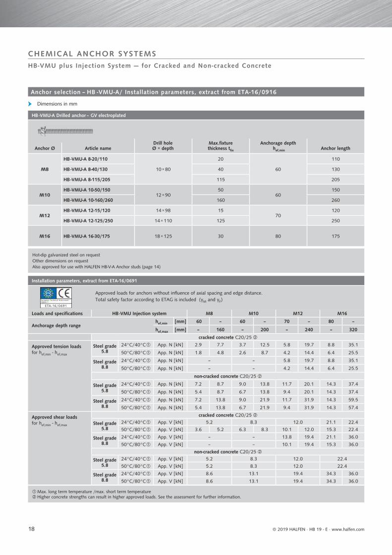
HB -VMU-A Drilled anchor – GV electroplated
Drill holeØ × depth
Max.fixture thickness tfix
Anchorage depth hef,min Anchor lengthAnchor Ø Article name
M8
HB -VMU-A 8-20/110
10 × 80
20
60
110
HB -VMU-A 8-40/130 40 130
HB -VMU-A 8-115/205 115 205
M10HB -VMU-A 10-50/150
12 × 9050
60150
HB -VMU-A 10-160/260 160 260
M12HB -VMU-A 12-15/120 14 × 98 15
70120
HB -VMU-A 12-125/250 14 × 110 125 250
M16 HB -VMU-A 16-30/175 18 × 125 30 80 175
Installation parameters, extract from ETA-16/0691
Approved loads for anchors without influence of axial spacing and edge distance.Total safety factor according to ETAG is included (γM and γF)
Loads and specifications HB -VMU Injection system M8 M10 M12 M16
Anchorage depth rangehef,min [mm] 60 – 60 – 70 – 80 –
hef,max [mm] – 160 – 200 – 240 – 320
cracked concrete C20/25
Approved tension loadsfor hef,min - hef,max
Steel grade 5.8
24°C/40°C App. N [kN] 2.9 7.7 3.7 12.5 5.8 19.7 8.8 35.1
50°C/80°C App. N [kN] 1.8 4.8 2.6 8.7 4.2 14.4 6.4 25.5
Steel grade 8.8
24°C/40°C App. N [kN] – – 5.8 19.7 8.8 35.1
50°C/80°C App. N [kN] – – 4.2 14.4 6.4 25.5
non-cracked concrete C20/25
Steel grade 5.8
24°C/40°C App. N [kN] 7.2 8.7 9.0 13.8 11.7 20.1 14.3 37.4
50°C/80°C App. N [kN] 5.4 8.7 6.7 13.8 9.4 20.1 14.3 37.4
Steel grade 8.8
24°C/40°C App. N [kN] 7.2 13.8 9.0 21.9 11.7 31.9 14.3 59.5
50°C/80°C App. N [kN] 5.4 13.8 6.7 21.9 9.4 31.9 14.3 57.4
Approved shear loadsfor hef,min - hef,max
cracked concrete C20/25
Steel grade 5.8
24°C/40°C App. V [kN] 5.2 8.3 12.0 21.1 22.4
50°C/80°C App. V [kN] 3.6 5.2 6.3 8.3 10.1 12.0 15.3 22.4
Steel grade 8.8
24°C/40°C App. V [kN] – – 13.8 19.4 21.1 36.0
50°C/80°C App. V [kN] – – 10.1 19.4 15.3 36.0
non-cracked concrete C20/25
Steel grade 5.8
24°C/40°C App. V [kN] 5.2 8.3 12.0 22.4
50°C/80°C App. V [kN] 5.2 8.3 12.0 22.4
Steel grade 8.8
24°C/40°C App. V [kN] 8.6 13.1 19.4 34.3 36.0
50°C/80°C App. V [kN] 8.6 13.1 19.4 34.3 36.0
© 2019 HALFEN · HB 19 - E ⋅ www.halfen.com
CHEMICAL ANCHOR SYSTEMSHB-VMU plus Injection System — for Cracked and Non-cracked Concrete
Anchor selection – HB -VMU-A/ Installation parameters, extract from ETA-16/0916
Dimensions in mm
Option 1
ETA -16/0691
European Technical Assessment -

19
Processing and curing times
Temperature (°C) in the drill hole ≥ -10°C ≥ -5°C ≥ 0°C ≥ +5°C ≥ +10°C ≥ +20°C ≥ +30°C ≥ +35°C ≥ +40°C
Processing time in hh:mm 01:30 01:30 00:45 00:25 00:15 00:06 00:04 00:02 90 sec.
Curing time inhh:mm
Dry concrete 24:00 14:00 07:00 02:00 01:20 00:45 00:25 00:20 00:15
Wet concrete 48:00 28:00 14:00 04:00 02:40 01:30 00:50 00:40 00:30
© 2019 HALFEN · HB 19 - E · www.halfen.com
Anchor length
HB-VMU plus Injection System A4 — for Cracked and Non-cracked Concrete
CHEMICAL ANCHOR BOLT SYSTEMS
Used for anchorage in non-cracked concrete in dry interior or also in exterior (non-aggressive) environments for base plates, fixings to walls and columns, fixings of expansion joint systems.
ApplicationsBenefitsDescription
Installation
HB -VMU-A A4 Drilled anchor
HB -VMU plus 280 CartridgeHB -VMU plus 410 Cartridge
HB-V VMU plus A4
Load range (tension): 2.9 kN – 42.1 kN
Concrete grade: C20/25 – C50/60
-10°C to +40°C = approved minimum temperature in installation material (concrete)
-40°C bis+120°C = Ambient temperature after the mortar has set (concrete)
www.halfen.com ►► Downloads ►► Software/CAD
Easy-to-use and free calculation software available
Option 1
ETA -16/0691
European Technical Assessment -
STAINLESS STEEL
The HB-VMU plus injection system is a general fixing system for almost all applications and building materials.
• an injection mortar for almost all applications; less storage space required, more versatile, and more reliable in application
• approved for cracked and non-cracked concrete
• more versatile with variable anchor-age depths
• use a new static mixer to continue using previously opened cartridges
• styrene-free 2-component vinyl ester based mortar — approved for use in seismic applications (category C1)
45min
+20 °C
90°

20
Installation specifications
Anchor stud M8 M10 M12 M16
Drill hole diameter do 10 12 14 18
Diameter of clearance hole in the fixture df 9 12 14 18
Spanner/wrench size SW 13 17 19 24
Installation torque
Tinst [Nm]
M8 10
M10 20
M12 40
M16 80
Axial spacing and edge distances
Anchor stud M8 M10 M12 M16
Anchorage depth rangehef,min 60 60 70 80
hef,max 160 200 240 320
Minimal building component thickness for hef,min hmin 100 100 100 116
Minimal building component thickness for hef,max hmin 190 230 270 356
Minimum axial spacing smin 40 50 60 80
Minimum edge distance cmin 40 50 60 80
© 2019 HALFEN · HB 19 - E ⋅ www.halfen.com
CHEMICAL ANCHOR BOLT SYSTEMS
Installation
Anchor length
Ordering example
Dimensions in mm
HB -VMU-A 8 ‒ 20/110 A4
HALFEN Anchor type
Diameter / thread [mm]Max. fixture thickness / total length [mm]
Finish
HB-VMU plus Injection System A4 — for Cracked and Non-cracked Concrete
≥ hmin
hef = h0tfi x
Tinst
d0s
cc
h
s df

21
Max. long term temperature /max. short term temperatureHigher concrete strengths may result in higher approved loads. Refer to assessment ETA-16/0691 for more information.
Installation parameters, extract from ETA-16/0691
Approved loads for anchors without influence of axial spacing and edge distance.Total safety factor according to ETAG is included (γM and γF)
Loads and specifications M8 M10 M12 M16
Anchorage depth rangehef,min [mm] 60 – 60 – 70 – 80 –
hef,max [mm] – 160 – 200 – 240 – 320
cracked concrete C20/25
Approved tension loads for hef,min - hef,max
24°C/40°C App. N [kN] 2.9 7.7 3.7 12.5 5.8 19.7 8.8 35.1
50°C/80°C App. N [kN] 1.8 4.8 2.6 8.7 4.2 14.4 6.4 25.5
non-cracked concrete C20/25
24°C/40°C App. N [kN] 7.2 9.8 9.0 15.5 11.7 22.6 14.3 42.1
50°C/80°C App. N [kN] 5.4 9.8 6.7 15.5 9.4 22.6 14.3 42.1
Approved shear loads for hef,min - hef,max
cracked concrete C20/25
24°C/40°C App. V [kN] 5.7 5.9 9.0 9.3 13.5 21.1 25.2
50°C/80°C App. V [kN] 3.6 5.9 6.3 9.3 10.1 13.5 15.3 25.2
non-cracked concrete C20/25
24°C/40°C App. V [kN] 5.9 9.3 13.5 25.2
50°C/80°C App. V [kN] 5.9 9.3 13.5 25.2
HB -VMU-A Drilled anchor – A4 Stainless steel (HCR on request)
Drill holeØ × depth
Anchorage depth hef,min
Max. fixture thickness tfix Anchor lengthAnchor Ø Article name
M8
HB -VMU-A 8-20/110
10 × 80 60
20 110
HB -VMU-A 8-40/130 40 130
HB -VMU-A 8-70/160 70 160
M10
HB -VMU-A 10-30/130
12 × 90 60
30 130
HB -VMU-A 10-50/165 50 165
HB -VMU-A 10-65/165 65 165
HB -VMU-A 10-90/190 90 190
M12
HB -VMU-A 12-15/120 14 × 98
70
15 120
HB -VMU-A 12-50/175
14 × 110
50 175
HB -VMU-A 12-85/210 85 210
HB -VMU-A 12-125/250 125 250
M16HB -VMU-A 16-15/160
18 × 125 80 15 160
HB -VMU-A 16-60/210 60 210
Also approved for use with HALFEN HB-V-A Anchor studs (see page 17)
© 2019 HALFEN · HB 19 - E · www.halfen.com
CHEMICAL ANCHOR BOLT SYSTEMS
Dimensions in mm
Anchor selection – HB -VMZ-A A4 Stainless steel / Installation parameters, extract from ETA-16/0691
HB-VMU plus Injection System A4 — for Cracked and Non-cracked Concrete
Option 1
ETA -16/0691
European Technical Assessment -

22
Processing and curing times
Temperature (°C) in the drill hole ≥ -10°C ≥ -5°C ≥ 0°C ≥ +5°C ≥ +10°C ≥ +20°C ≥ +30°C ≥ +35°C ≥ +40°C
Processing time in hh:mm 01:30 01:30 00:45 00:25 00:15 00:06 00:04 00:02 90 sec.
Curing time in hh:mm
Dry concrete 24:00 14:00 07:00 02:00 01:20 00:45 00:25 00:20 00:15
Wet concrete 48:00 28:00 14:00 04:00 02:40 01:30 00:50 00:40 00:30
© 2019 HALFEN · HB 19 - E ⋅ www.halfen.com
HB-VMU plus Injection System for Masonry — Electroplated and A4
CHEMICAL ANCHOR BOLT SYSTEMS
HB-V VMU plus — electroplated and A4
www.halfen.com ►► Downloads ►► Software/CAD
Easy-to-use and free calculation software available
ApplicationsDescription
Installation
Load range (tension): 0.17 kN – 2.32 kN
Benefits
The HB -VMZ Injection system is an expansion pressure free anchorage for monolithic and perforated masonry. The system consists of a styrene-free vinyl ester resin and a hardener compo-nent as bonding agent in a cartridge and a threaded rod as anchoring ele-ment. Using a HB-VM-P Silicone gun with attached HB -VM-X Static mixer, the bonding agent is pressed into the drill hole with an inserted perfo sleeve for perforated brick or without a sleeve for monolithic brick. The threaded rod is inserted in the hole by hand. The anchor element is securely fixed after the bonding agent has hardened.
Anchorage in masonry in dry interior walls. A4 stainless steel anchors can also be used in outdoor environments or in wet rooms (non-aggressive environments): door canopies, door and window frames, support structures for façades, or other timber or wood ancillary constructions.
• an injection mortar for almost all applications; more flexibility, less required storage space, more reliable in application
• widely approved for cracked and non-cracked concrete, and also for masonry.
HB -VMU-A Drilled anchor electroplated or A4 HB -VM-SH Perfo sleeve
HB -VMU plus 280 CartridgeHB -VMU plus 410 Cartridge
-5°C = approved minimum temperature in installation material (concrete)
ETA-17/0196
European Technical Assessment -Category b,c,d
STAINLESS STEEL
-40°C bis+120°C = Ambient temperature after the mortar has set (concrete)
45min
+20 °C
Nm
TINST
SH Perfo sleeve

23
Installation torque
Tinst [Nm]
HB -VMU-A
M82
(14 Nm for masonry brick
Mz-DF)
M10
M12
M16
Installation specifications
Anchor studHB -VMU-A
M8 M10 M12 M16
Drill hole diameter with perfo sleeve do 12 16 20 20
Drill hole diameter, no perfo sleeve (monolithic brick) do 10 12 14 18
Diameter of clearance hole in the fixture df 9 12 14 18
Drill hole diameter with perfo sleeve h0 85 90 90 135
Drill hole diameter, no perfo sleeve (monolithic brick) h0 80 90 100 100
Diameter cleaning brush with/without perfo sleeve dB 10/12 12/16 14/20 18/20
Installation in perforated bricks with perfo sleeve
Anchor stud suitable perfo sleeve
HB-VMU-A M8 HB-VM-SH 12
HB-VMU-A M10 HB-VM-SH 16
HB-VMU-A M12 HB-VM-SH 20
HB-VMU-A M16 HB-VM-SH 20
Installation in monolithic bricks without perfo sleeve
Anchor stud
HB-VMU-A M8
HB-VMU-A M10
HB-VMU-A M12
HB-VMU-A M16
© 2019 HALFEN · HB 19 - E · www.halfen.com
HB-VMU plus Injection System for Masonry — Electroplated and A4
CHEMICAL ANCHOR BOLT SYSTEMS
Installation specifications
Dimensions in mm
ho
hef
≥ hmin
tfi x
≥ hmin
ho
heftfi x
d0
Tinst
Tinst
df
df
24
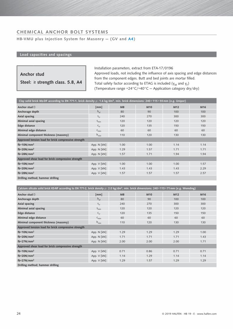
Clay solid brick Mz-DF according to EN 771-1, brick density ρ : 1.6 kg/dm3, min. brick dimensions: 240 × 115 × 55 mm (e.g. Unipor)
Anchor stud [mm] M8 M10 M12 M16
Anchorage depth hef 80 90 100 100
Axial spacing scr 240 270 300 300
Minimal axial spacing smin 120 120 120 120
Edge distance ccr 120 135 150 150
Minimal edge distance cmin 60 60 60 60
Minimal component thickness (masonry) hmin 110 120 130 130
Approved tension load for brick compressive strength
fb=10N/mm2 App. N [kN] 1.00 1.00 1.14 1.14
fb=20N/mm2 App. N [kN] 1.29 1.57 1.71 1.71
fb=28N/mm2 App. N [kN] 1.57 1.71 1.94 1.94
Approved shear load for brick compressive strength
fb=10N/mm2 App. V [kN] 1.00 1.00 1.00 1.57
fb=20N/mm2 App. V [kN] 1.43 1.43 1.43 2.29
fb=28N/mm2 App. V [kN] 1.57 1.57 1.57 2.57
Drilling method; hammer drilling
Calcium silicate solid brick KS-NF according to EN 771-2, brick density ρ : 2.0 kg/dm3, min. brick dimensions: 240 × 115 × 71 mm (e.g. Wemding)
Anchor stud [mm] M8 M10 M12 M16
Anchorage depth hef 80 90 100 100
Axial spacing scr 240 270 300 300
Minimal axial spacing smin 120 120 120 120
Edge distance ccr 120 135 150 150
Minimal edge distance cmin 60 60 60 60
Minimal component thickness (masonry) hmin 110 120 130 130
Approved tension load for brick compressive strength
fb=10N/mm2 App. N [kN] 1.29 1.29 1.29 1.00
fb=20N/mm2 App. N [kN] 1.71 1.71 1.71 1.43
fb=27N/mm2 App. N [kN] 2.00 2.00 2.00 1.71
Approved shear load for brick compressive strength
fb=10N/mm2 App. V [kN] 0.71 0.86 0.71 0.71
fb=20N/mm2 App. V [kN] 1.14 1.29 1.14 1.14
fb=27N/mm2 App. V [kN] 1.29 1.57 1.29 1.29
Drilling method; hammer drilling
© 2019 HALFEN · HB 19 - E ⋅ www.halfen.com
Anchor stud
Steel: ≥ strength class. 5.8, A4
Load capacities and spacings
Installation parameters, extract from ETA-17/0196Approved loads, not including the influence of axis spacing and edge distances from the component edges. Butt and bed joints are mortar filled.Total safety factor according to ETAG is included (γM and γF)(Temperature range +24°C/+40°C — Application category dry/dry)
CHEMICAL ANCHOR BOLT SYSTEMSHB-VMU plus Injection System for Masonry — (GV and A4)

25
Clay hollow brick, Porotherm Homebric acc. to EN 771-1, brick density ρ : 0.7 kg/dm3, min. brick dimensions: 500 × 200 × 299 mm (e.g. Wienerberger)
M8/ M10 M12 M16
Perfo sleeve VM-SH 16×85 20×85 20×130
Anchorage depth hef 85 85 130
Axial spacing parallel to the bed joint scr, II 500 500 500
Axial spacing perpendicular to the bed joint scr,┴ 300 300 300
Minimal axial spacing smin 100 100 100
Edge distance ccr 100 120 120
Minimal edge distance cmin➃ 100 120 120
Minimal component thickness (masonry) hmin 115 115 175
Approved tension load for brick compressive strength
fb=4N/mm2 App. N [kN] 0.26 0.26 0.34
fb=6N/mm2 App. N [kN] 0.26 0.26 0.34
fb=10N/mm2 App. N [kN] 0.34 0.34 0.43
Approved shear load for brick compressive strength
fb=4N/mm2 App. V [kN] 0.57 0.71 0.71
fb=6N/mm2 App. V [kN] 0.71 0.86 0.86
fb=10N/mm2 App. V [kN] 0.86 1.14 1.14
Solid lightweight concrete LAC acc. to EN 771-3, brick density ρ : 0.6 kg/dm3, min. brick dimensions: 300 × 123 × 248 mm (e.g. Bisotherm)
Anchor stud M8 M10 M12 M16
Anchorage depth hef 80 90 100 100
Axial spacing scr 240 270 300 300
Minimal axial spacing smin 120 120 120 120
Edge distance ccr 120 135 150 150
Minimal edge distance cmin 60 60 60 60
Minimal component thickness (masonry) hmin 110 120 130 130
Approved tension load for brick compressive strength
fb=6N/mm2 App. N [kN] 0.86 0.86 1.00 0.86
Approved shear load for brick compressive strength
fb=6N/mm2 App. V [kN] 0.86 0.86 0.86 0.86
Drilling method; hammer drilling
Autoclaved Aerated concrete AAC6 acc. to EN 771-4, brick density ρ : 0.6 kg/dm3, min. brick dimensions: 499 × 240 × 249 mm (e.g. Porit)
Anchor stud M8 M10 M12 M16
Anchorage depth hef 80 90 100 100
Axial spacing scr 240 270 300 300
Minimal axial spacing smin 100 100 100 100
Edge distance ccr 120 135 150 150
Minimal edge distancecmin,N 75 75 75 75
cmin,v, II 75 75 75 75cmin,v,┴
120 135 150 150
Minimal component thickness (masonry) hmin 110 120 130 130
Approved tension load for brick compressive strength
fb=2N/mm2 App. N [kN] 0.89 1.43 1.79 2.32
Approved shear load for brick compressive strength
fb=2N/mm2 App. V [kN] 2.14 3.57 3.57 3.57
Drilling method; rotary drilling
© 2019 HALFEN · HB 19 - E · www.halfen.com
Load capacities and spacings
Can also be installed with perfo sleeve; see ETA-17/0196 for technical specificationsMinimum edge distance Cmin,v, II for shear loads parallel to the free edge
Minimum edge distance Cmin,v,┴ for shear loads parallel to the free edge➃ For VRk,c: cmin according to ETAG029, annex C
CHEMICAL ANCHOR BOLT SYSTEMSHB-VMU plus Injection System for Masonry — (GV and A4)

26
Clay hollow brick, HLz-16-DF according to EN 771-1, brick density ρ : 0.8 kg/dm3, min. brick dimensions: 497 × 240 × 238 mm (e.g. Unipor)
M8/ M10 M12/M16
VM-SH Perfo sleeve [mm] 16×85 20×85 20×130 20×200
Anchorage depth hef 85 85 130 200
Axial spacing parallel to the bed joint scr, II 497 497 497 497
Axial spacing perpendicular to the bed joint scr,┴ 238 238 238 238
Minimal axial spacing smin 100 100 100 100
Edge distance ccr 100 120 120 120
Minimal edge distance cmin 100 120 120 120
Minimal component thickness (masonry) hmin 115 115 175 240
Approved tension load for brick compressive strength
fb=6N/mm2 App. N [kN] 0.71 0.71 1.00 1.00
fb=8N/mm2 App. N [kN] 0.86 0.86 1.29 1.29
fb=12N/mm2 App. N [kN] 1.00 1.00 1.43 1.43
fb=14N/mm2 App. N [kN] 1.14 1.14 1.57 –
Approved shear load for brick compressive strength
fb=6N/mm2 App. V [kN] 1.29 1.43 1.71 1.71
fb=8N/mm2 App. V [kN] 1.57 1.71 2.00 2.00
fb=12N/mm2 App. V [kN] 1.86 2.00 2.57 2.57
fb=14N/mm2 App. V [kN] 1.86 2.00 2.57 2.57
Clay hollow brick (Doppio Uni) according to EN 771-1, brick density ρ : 0.9 kg/dm3, min. brick dimensions: 250 × 120 × 120 mm (e.g. Wienerberger)
M8/ M10 M12/M16
VM-SH Perfo sleeve [mm] 16×85 20×85 20×130 20×200
Anchorage depth hef 85 85 130 200
Axial spacing parallel to the bed joint scr, II 250 250 250 250
Axial spacing perpendicular to the bed joint scr,┴ 120 120 120 120
min. axial spacing parallel to the bed joint smin, I 100 100 100 100
Minimal axial spacing smin 120 120 120 120
Edge distance ccr 100 120 120 120
Minimal edge distance cmin 60 60 60 60
Minimal component thickness (masonry) hmin 115 115 175 240
Approved tension load for brick compressive strength
fb=10N/mm2 App. N [kN] 0.17 0.17 0.17 0.17
fb=16N/mm2 App. N [kN] 0.21 0.21 0.21 0.21
fb=20N/mm2 App. N [kN] 0.26 0.26 0.26 0.26
fb=28N/mm2 App. N [kN] 0.34 0.34 0.34 0.34
Approved shear load for brick compressive strength
fb=10N/mm2 App. V [kN] 0.43 0.43 0.43 0.43
fb=16N/mm2 App. V [kN] 0.57 0.57 0.57 0.57
fb=20N/mm2 App. V [kN] 0.57 0.57 0.57 0.57
fb=28N/mm2 App. V [kN] 0.71 0.71 0.71 0.71
© 2019 HALFEN · HB 19 - E ⋅ www.halfen.com
CHEMICAL ANCHOR BOLT SYSTEMS
Load capacities and spacings
For VRk,c: cmin according to ETAG029, annex C
HB-VMU plus Injection System for Masonry — (GV and A4)

27
Calcium silicate hollow brick KSL-3DF acc. to EN 771-2, brick density ρ : 1.4 kg/dm3, min. brick dimensions: 240 × 175 × 113 mm (e.g. Wemding)
M8/ M10 M12/M16
VM-SH Perfo sleeve [mm] 16×85 20×85 20×130 20×200
Anchorage depth hef 85 85 130 200
Axial spacing parallel to the bed joint scr, II 240 240 240 240
Axial spacing perpendicular to the bed joint scr,┴ 120 120 120 120
min. axial spacing smin 120 120 120 120
Edge distance ccr 100 120 120 120
Minimal edge distance cmin 60 60 60 60
Minimal component thickness (masonry) hmin 115 115 175 240
Approved tension load for brick compressive strength
fb=8N/mm2 App. N [kN] 0.43 1.29 1.29 1.29
fb=12N/mm2 App. N [kN] 0.57 1.71 1.71 1.71
fb=14N/mm2 App. N [kN] 0.71 1.86 1.86 1.86
Approved shear load for brick compressive strength
fb=8N/mm2 App. V [kN] 1.14 1.14 1.14 1.14
fb=12N/mm2 App. V [kN] 1.29 1.29 1.29 1.29
fb=14N/mm2 App. V [kN] 1.71 1.71 1.71 1.71
Calcium silicate hollow brick KSL-12DF acc. to EN 771-2, brick density ρ : 1.4 kg/dm3, min. brick dimensions: 498 × 175 × 238 mm (e.g. Wemding)
M8/ M10 M12/M16
VM-SH Perfo sleeve [mm] 16×85 20×85 20×130
Anchorage depth hef 85 85 130
Axial spacing parallel to the bed joint scr, II 498 498 498
Axial spacing perpendicular to the bed joint scr,┴ 238 238 238
min. axial spacing smin 120 120 120
Edge distance ccr 100 120 120
Minimal edge distance cmin 100 120 120
Minimal component thickness (masonry) hmin 115 115 175
Approved tension load for brick compressive strength
fb=10N/mm2 App. N [kN] 0.17 0.43 0.71
fb=12N/mm2 App. N [kN] 0.21 0.43 0.86
fb=16N/mm2 App. N [kN] 0.26 0.57 1.14
Approved shear load for brick compressive strength
fb=10N/mm2 App. V [kN] 1.57 1.57 1.57
fb=12N/mm2 App. V [kN] 1.86 1.86 1.86
fb=16N/mm2 App. V [kN] 2.29 2.29 2.29
Hollow lightweight concrete block (Bloc creux) B40 acc. to EN 771-3, brick density ρ : 0.8 kg/dm3, min. brick dimensions: 494 × 200 × 190 mm (e.g. Sepa)
M8/ M10 M12/M16
VM-SH Perfo sleeve [mm] 16×85 20×85 20×130
Anchorage depth hef 85 85 130
Axial spacing parallel to the bed joint scr, II 494 494 494
Axial spacing perpendicular to the bed joint scr,┴ 190 190 190
min. axial spacing smin 100 100 100
Edge distance ccr 100 120 120
Minimal edge distance cmin 100 120 120
Minimal component thickness (masonry) hmin 115 115 175
Approved tension load for brick compressive strength
fb=4N/mm2 App. N [kN] 0.34 0.34 0.34
Approved shear load for brick compressive strength
fb=4N/mm2 App. V [kN] 0.86 0.86 0.86
© 2019 HALFEN · HB 19 - E · www.halfen.com
CHEMICAL ANCHOR BOLT SYSTEMS
Load capacities and spacings
HB-VMU plus Injection System for Masonry — (GV and A4)

28
HB-VMU-A 12 for application in monolithic masonry without perfo sleeve (page 23) Not including the perfo sleeve
HB -VMU-A Drilled anchor ‒ GV
Anchor Ø Article nameDrill holeØ × depth
Anchorage depth hef,min
fixture thickness tfix,
Anchor length
M8
HB -VMU-A 8-20/110
10 × 80 60
20 110
HB -VMU-A 8-40/130 40 130
HB -VMU-A 8-115/205 115 205
M10HB -VMU-A 10-50/150
12 × 90 6050 150
HB -VMU-A 10-160/260 160 260
M12HB -VMU-A 12-15/120 14 × 98
7015 120
HB -VMU-A 12-125/250 14 × 110 125 250
M16 HB -VMU-A 16-30/175 18 × 125 80 30 175
HB -VMU-A Drilled anchor ‒ A4
Anchor Ø Article nameDrill holeØ × depth
Anchorage depth hef,min
fixture thickness tfix,
Anchor length
M8
HB -VMU-A 8-20/110
10 × 80 60
20 110
HB -VMU-A 8-40/130 40 130
HB -VMU-A 8-70/160 70 160
M10
HB -VMU-A 10-30/130
12 × 90 60
30 130
HB -VMU-A 10-50/150 50 150
HB -VMU-A 10-90/190 90 190
M12
HB -VMU-A 12-15/120 14 × 98
70
15 120
HB -VMU-A 12-50/175
14 × 110
50 175
HB -VMU-A 12-85/210 85 210
HB -VMU-A 12-125/250 125 250
M16 HB -VMU-A 16-15/160 18 × 125 80 15 160
© 2019 HALFEN · HB 19 - E · www.halfen.com
CHEMICAL ANCHOR BOLT SYSTEMS
Anchor se lect ion – HB -VMU-A A4 /e lect roplated
HB-VMU plus Injection System for Masonry — (GV and A4)
HB -VMU-A 8 ‒ 20/110 A4
HALFEN Anchor type
Diameter / thread[mm]Max. fixture thickness / total length [mm]
Finish
O r d e r i n g e x a m p l e
Dimensions in mm

29© 2019 HALFEN · HB 19 - E · www.halfen.com
HB -BZ Wedge anchorThe HB-BZ Wedge Anchor can be used in a variety of applications, in non-cracked as well as cracked concrete. The anchor ensures ample friction and therefore reliable anchoring, even in cracked concrete.See page 30
Design softwarePage 45
Fire resistance table HB-BZ Bolt anchor
Page 46
ContactsPage 47
Mechanical Anchor SystemsHALFEN Anchor bolts
HB -B Wedge anchorThe HB-B Wedge anchor is a veryeconomical anchor for simple and fastinstallation in non-cracked concrete.Mainly used for standard applications.See page 37
HB -BZ-IG Bolt anchor on request
HB -B-IG Bolt anchor on request
ServiceOur Customer Service andTechnical Field Support Teamsare available to providecomprehensive support forspecifi c applications or to providesolutions for complete projects.
www.dnvgl.com
NOTES REGARDING THIS CATALOGUETechnical and design changes reserved. The information in this publication is based on state-of-the-art technology at the time of publication. We reserve the right to make technical and design changes at any time. HALFEN GmbH shall not accept liability for the accuracy of the information in this publication or for any printing errors.
The HALFEN GmbH subsidiaries in Germany, France, the Netherlands, Austria, Poland, Switzerland and the Czech Republic are Quality Management certified according to ISO 9001:2015, Certificate no. 202384-2016-AQ-GER-DAkkS.
Austria HALFEN Gesellschaft m.b.H.Leonard-Bernstein-Str. 101220 Wien
Phone: +43 - 1 - 259 6770 E-Mail: [email protected]: www.halfen.at
Belgium / Luxembourg HALFEN N.V.Borkelstraat 1312900 Schoten
Phone: +32 - 3 - 658 07 20E-Mail: [email protected]: www.halfen.be
Fax: +32 - 3 - 658 15 33
China HALFEN Construction Accessories Distribution Co.Ltd.Room 601 Tower D, Vantone CentreNo. A6 Chao Yang Men Wai StreetChaoyang District Beijing · P.R. China 100020
Phone: +86 - 10 5907 3200E-Mail: [email protected]: www.halfen.cn
Fax: +86 - 10 5907 3218
Czech Republic HALFEN s.r.o.Business Center ŠafránkovaŠafránkova 1238/1155 00 Praha 5
Phone: +420 - 311 - 690 060E-Mail: [email protected]: www.halfen.cz
Fax: +420 - 235 - 314 308
France HALFEN S.A.S.18, rue Goubet75019 Paris
Phone: +33 - 1 - 445231 00E-Mail: [email protected]: www.halfen.fr
Fax: +33 - 1 - 445231 52
Germany HALFEN Vertriebsgesellschaft mbHLiebigstr. 14 40764 Langenfeld
Phone: +49 - 2173 - 970 - 0E-Mail: [email protected]: www.halfen.de
Fax: +49 - 2173 - 970 225
Italy HALFEN S.r.l. Soc. UnipersonaleVia F.lli Bronzetti N° 2824124 Bergamo
Phone: +39 - 035 - 0760711E-Mail: [email protected]: www.halfen.it
Fax: +39 - 035 - 0760799
Netherlands HALFEN b.v.Oostermaat 37623 CS Borne
Phone: +31 - 74-267 14 49E-Mail: [email protected]: www.halfen.nl
Fax: +31 - 74-267 26 59
Norway HALFEN ASPostboks 20804095 Stavanger
Phone: +47 - 51 82 34 00E-Mail: [email protected]: www.halfen.no
Poland HALFEN Sp. z o.o.Ul. Obornicka 28760-691 Poznan
Phone: +48 - 61 - 622 14 14E-Mail: [email protected]: www.halfen.pl
Fax: +48 - 61 - 622 14 15
Spain HALFEN IBERICA, S.L.Polígono Industrial Santa Ana c/ Ignacio Zuloaga 2028522 Rivas-Vaciamadrid
Phone: +34 - 91 632 18 40E-Mail: [email protected]: www.halfen.es
Fax: +34 - 91 633 42 57
Sweden Halfen ABVädursgatan 5412 50 Göteborg
Phone: +46 - 31 - 98 58 00E-Mail: [email protected]: www.halfen.se
Fax: +46 - 31 - 98 58 01
Switzerland HALFEN Swiss AGHertistrasse 25 8304 Wallisellen
Phone: +41 - 44 - 849 78 78E-Mail: [email protected]: www.halfen.ch
Fax: +41 - 44 - 849 78 79
United Kingdom /Ireland
HALFEN Ltd.A1/A2 Portland CloseHoughton Regis LU5 5AW
Phone: +44 - 1582 - 47 03 00E-Mail: [email protected]: www.halfen.co.uk
Fax: +44 - 1582 - 47 03 04
United States of America HALFEN USA Inc. PO Box 18687 San Antonio TX 78218
Phone: +1 800.423.91 40E-Mail: [email protected]: www.halfenusa.com
Fax: +1 877.683.4910
For countries not listed HALFEN International
HALFEN International GmbHLiebigstr. 14 40764 Langenfeld / Germany
Phone: +49 - 2173 - 970 - 0 E-Mail: [email protected]: www.halfen.com
Fax: +49 - 2173 - 970 - 849
CONTACT HALFEN WORLDWIDE
HALFEN is represented by subsidiaries in the following countries, please contact us!
The performance of the HALFEN range of Mechanical
Anchor Systems has been further inproved.
Fire tested
i
i

30
Installation torque
Tinst [Nm]
M8 20
M10 25
M12 45
M16 90
M20 160
M24 200
Installation specifications
Anchor bolts M8 M10 M12 M16 M20 M24Drill hole diameter do 8 10 12 16 20 24
Diameter of clearance hole in the fixture df 9 12 14 18 22 26
Drill hole depth h1 60 75 90 110 125 145
Spanner/wrench size SW 13 17 19 24 30 36
© 2019 HALFEN · HB 19 - E ⋅ www.halfen.com
HB-BZ Wedge Anchor Electroplated — for Cracked and Non-cracked Concrete
MECHANICAL ANCHOR SYSTEMS
HB -BZ Wedge Anchor HB -BZ-U Wedge Anchor
HB-BZ Wedge anchor ‒ electroplated
www.halfen.com ►► Downloads ►► Software/CAD
Easy-to-use and free calculation software available
Option 1
ETA -07/0249
European Technical Assessment -
ApplicationsDescription
I n s t a l l a t i o n
Load range (tension): 2.4 kN – 45.9 kN
Concrete grade: C20/25 – C50/60
The HB-BZ Wedge anchor’s performance and application have been furtherimproved. Another new feature is theapproval for application in category C1 and C2 seismic zones.
Anchorage of medium to heavy loads in cracked and non-cracked concrete in dry interior environments: Columns, steel supports, handrail and banister fixing, cable ducts and trays, timber structures, consoles. Also suitable for application in earth-quake zones.
Fire tested
Nm
90°
c c
h
s s
h1h1,red
hefhef,red
tfix tfix
h≥hmin1 or hmin2 h≥hmin3
TinstTinst
df df

31
Axial and edge distance for standard thickness building components
Anchor bolts [mm] M8 M10 M12 M16 M20 M24
Anchorage depth hef 46 60 70 85 100 115
Min. thickness building component hmin,1 100 120 140 170 200 230
cracked concrete
Min. axial spacing / for edge distance c smin / c 40 / 70 45/70 60 / 100 60 / 100 95 / 150 100/180
Min. edge distance / for axial spacing s cmin / s 40 / 80 45/90 60 / 140 60 / 180 95 / 200 100/220
non-cracked concrete
Min. axial spacing / for edge distance c smin / c 40 / 80 45/70 60 / 120 65 / 120 90 / 180 100/180
Min. edge distance / for axial spacing s cmin / s 50 / 100 50/100 75 / 150 80 / 150 130 / 240 100/220
Axial and edge distance for reduced min. thickness building componentsAnchor bolts [mm] M8 M10 M12 M16 M20 M24Min. thickness building component hmin,2 80 100 120 140 - -
cracked concrete
Min. axial spacing / for edge distance c smin / c 40 / 70 45 / 90 60 / 100 70 / 160 - -
Min. edge distance / for axial spacing s cmin / s 40 / 80 50 / 115 60 / 140 80 / 180 - -
non-cracked concrete
Min. axial spacing / for edge distance c cmin / c 40 / 80 60 / 140 60 / 120 80 / 180 - -
Min. edge distance / for axial spacing s cmin / s 50 / 100 90 / 140 75 / 150 90 / 200 - -
Reduced anchorage depthsAnchor bolts [mm] M8 M10 M12 M16 M20 M24Min. thickness building component hmin,3 80 80 100 140 - -
Drill hole depth h1red 49 55 70 90 - -
Reduced effective anchorage depth hef,red 35 40 50 65 - -
cracked concrete
Min. axial spacing / for edge distance c smin / c 50/60 50/100 50/160 65/170 - -
Min. edge distance / for axial spacing s cmin / s 40/185 65/180 65/250 100/250 - -
non-cracked concrete
Min. axial spacing / for edge distance c smin / c 50 / 60 50 / 100 50 / 160 65 / 170 - -
Min. edge distance / for axial spacing s cmin / s 40 / 185 65 / 180 100 / 185 170 / 65 - -
Installation parameters, extract from ETA-07/0249
Approved loads for anchors without influence of axial spacing and edge distance.Total safety factor according to ETAG is included (γM and γF)
Loads and specifications – HB -BZ Bolt anchor M8 M10 M12 M16 M20 M24Standard anchorage depth hef [mm] – 46 – 60 – 70 – 85 100 115
Reduced anchorage depth hef, red [mm] 35 – 40 – 50 – 65 – – –
cracked concrete
Approved tension load C20/25 App. N [kN] 2.4 2.4 3.6 4.3 6.1 7.6 9.0 11.9 17.1 21.1C25/30 App. N [kN] 2.6 2.6 3.9 4.7 6.6 8.3 9.8 13.0 18.8 23.2C30/37 App. N [kN] 2.9 2.9 4.3 5.2 7.4 9.3 10.9 14.5 20.9 25.7C40/50 App. N [kN] 3.4 3.4 5.1 6.1 8.6 10.8 12.7 16.8 24.2 29.9C50/60 App. N [kN] 3.7 3.7 5.5 6.6 9.4 11.8 13.9 18.4 26.6 32.8
non-cracked concrete
Approved tension load C20/25 App. N [kN] 3.6 5.7 4.3 7.6 8.5 11.9 12.6 16.7 24.0 29.7C25/30 App. N [kN] 3.9 6.3 4.7 8.3 9.3 13.0 13.8 18.3 26.3 32.5C30/37 App. N [kN] 4.3 7.0 5.2 9.3 10.3 14.5 15.3 20.3 29.3 36.1C40/50 App. N [kN] 5.1 7.5 6.1 10.8 12.0 16.8 17.8 23.6 34.0 41.9C50/60 App. N [kN] 5.5 7.5 6.6 11.8 13.2 18.4 19.5 25.8 37.3 45.9
cracked concrete / non-cracked concreteApproved shear load C20/25 App. V [kN] 7.0 7.0 10.4/11.5 11.5 14.5/17.1 17.1 21.6/30.2 31.4 37.1 59.2/65.1
C25/30 App. V [kN] 7.0 7.0 11.4/11.5 11.5 15.9/17.1 17.1 23.6/31.4 31.4 37.1 64.8/65.1Approved bending moment – App. M [Nm] 13.1 13.1 26.9 26.9 46.9 46.9 123.4 123.4 195.0 513.1
© 2019 HALFEN · HB 19 - E · www.halfen.com
HB-BZ Wedge Anchor Electroplated — for Cracked and Non-cracked Concrete
MECHANICAL ANCHOR SYSTEMS
Dimensions in mm
Option 1
ETA -07/0249
European Technical Assessment -
Installation

32
HB -BZ Wedge anchor — GV electroplated
Standard anchorage depth Reduced anchorage depth
Fixture thickness
tfix
Drill holeØ×depth
Setting depthhnom
Anchoragedepth
hef
Fixture thickness
tfix,red
Drill holeØ×depth
Setting depthhnom,red
Anchoragedepth hef,red
AnchorlengthAnchor Ø Article name Thread
M8
HB-BZ 8-10-21/75 10
8 × 60 52 46
21
8 × 49 41 35
75 M8 × 32
HB-BZ 8-15-26/80 15 26 80 M8 × 37
HB-BZ 8-30-41/95 30 41 95 M8 × 52
HB-BZ 8-50-61/115 50 61 115 M8 × 72
M10
HB-BZ 10-10-30/90 10
10 × 75 68 60
30
10 × 55 48 40
90 M10 × 42
HB-BZ 10-15-35/95 15 35 95 M10 × 47
HB-BZ 10-20-40/100 20 40 100 M10 × 52
HB-BZ 10-30-50/110 30 50 110 M10 × 62
HB-BZ 10-50-70/130 50 70 130 M10 × 82
M12
HB-BZ 12-15-35/110 15
12 × 90 80 70
35
12 × 70 60 50
110 M12 × 51
HB-BZ 12-30-50/125 30 50 125 M12 × 66
HB-BZ 12-50-70/145 50 70 145 M12 × 86
HB-BZ 12-65-85/160 65 85 160 M12 × 101
HB-BZ 12-85-105/180 85 105 180 M12 × 121
HB-BZ 12-105-125/200 105 125 200 M12 × 141
M16
HB-BZ 16-15-35/135 15
16 × 110 97 85
35
16 × 90 77 65
135 M16 × 56
HB-BZ 16-25-45/145 25 45 145 M16 × 66
HB-BZ 16-50-70/170 50 70 170 M16 × 91
HB-BZ 16-80-100/200 80 100 200 M16 × 91
M20 HB-BZ 20-60/195 60 20 × 125 114 100 – – – – 195 M20 × 70
M24HB-BZ 24-30/190 30
24 × 145 133 115– – – – 190 M24 × 55
HB-BZ 24-60/220 60 – – – – 220 M24 × 85
HB -BZ-U Bolt anchor GV
Standard anchorage depth Reduced anchorage depth
Fixture thickness
tfix
Drill holeØ×depth
Setting depth
Anchoragedepth
hef
Fixture thickness
tfix,red
Drill holeØ×depth
Setting depthhnom,red
Anchoragedepth hef,red
Anchorlength
Ø U-washer ThreadAnchor Ø Article name
M8HB-BZ-U 8-15-26/80 15
8 × 60 52 4626
8 × 49 41 3580
24M8 × 37
HB-BZ-U 8-30-41/95 30 41 95 M8 × 52
M10HB-BZ-U 10-15-35/95 15 10 × 75 68 60 35 10 × 55 48 40 95 30 M10 × 47
HB-BZ-U 10-30-50/110 30 10 × 75 68 60 50 10 × 55 48 40 110 30 M10 × 62
M12
HB-BZ-U 12-15-35/110 15
12 × 90 80 70
35
12 × 70 60 50
110
37
M12 × 51
HB-BZ-U 12-30-50/125 30 50 125 M12 × 66
HB-BZ-U 12-50-70/145 50 70 145 M12 × 86
Please observe lower load capacities when using reduced anchorage depths. Further lengths on request.
© 2019 HALFEN · HB 19 - E ⋅ www.halfen.com
HB-BZ Wedge Anchor Electroplated — for Cracked and Non-Cracked Concrete
MECHANICAL ANCHOR SYSTEMS
S e l e c t i o n w e d g e a n c h o r s
Dimensions in mm
= Preferred anchor for HALFEN Applications
= Preferred anchor for HALFEN Applications
Not included in the assessment
With large washer, see EN ISO 7093 (DIN 9021)

33
Installation torque
Tinst [Nm]
M8 20
M10 35
M12 50
M16 110
M20 200
Installation specifications
Anchor bolts M8 M10 M12 M16 M20Drill hole diameter do 8 10 12 16 20
Diameter of clearance hole in the fixture df 9 12 14 18 22
Drill hole depth h1 60 75 90 110 125
Spanner/wrench size SW 13 17 19 24 30
© 2019 HALFEN · HB 19 - E · www.halfen.com
HB-BZ Wedge Anchor A4 Stainless Steel — for Cracked and Non-cracked Concrete
MECHANICAL ANCHOR SYSTEMS
HB -BZ-U Wedge Anchor A4HB -BZ Wedge Anchor A4
HB-BZ Wedge anchor — A4 Stainless steel
www.halfen.com ►► Downloads ►► Software/CAD
Easy-to-use and free calculation software available
Option 1
ETA -07/0249
European Technical Assessment -
STAINLESS STEEL
ApplicationsDescription
Installation
Load range (tension): 2.4 kN – 37.2 kN
Concrete grade: C20/25 – C50/60
Suitable for anchorage of medium to heavy loads in cracked and non-cracked concrete in dry interior or in exterior (non-aggressive) environments. Canbe used in cracked and non-cracked concrete: Columns, steel supports, consoles, access gates, fi xings forstadium seating and support structures for façades. Suitable for application in earthquake zones.
The HB-BZ Wedge anchor’s perfor-mance and application have been further improved. A new feature isthe approval for application incategory C1 and C2 seismic zones.
h ≥ hmin1 or hmin2
Fire tested
90°
Nm
c
c
h
ss
tfixh1 h1,red
hefhef,red tfix
h ≥ hmin3
TinstTinst
df df

34
Installation parameters, extract from assessment ETA-07/0249
Approved loads for anchors without influence of axial spacing and edge distance.Total safety factor according to ETAG is included (γM and γF)
Loads and specifications — HB -BZ Wedge anchor (A4) M8 M10 M12 M16 M20Standard anchorage depth hef [mm] 46 – 60 – 70 – 85 – 100
Reduced anchorage depth hef, red [mm] – 35 – 40 – 50 – 65 –cracked concrete
Approved tension loads C20/25 App. N [kN] 2.4 2.4 4.3 3.6 7.6 6.1 11.9 9.0 17.1C25/30 App. N [kN] 2.6 2.6 4.7 3.9 8.3 6.6 13.0 9.8 18.8C30/37 App. N [kN] 2.9 2.9 5.2 4.3 9.3 7.4 14.5 10.9 20.9C40/50 App. N [kN] 3.4 3.4 6.1 5.1 10.8 8.6 16.8 12.7 24.2C50/60 App. N [kN] 3.7 3.7 6.6 5.5 11.8 9.4 18.4 13.9 26.6
non-cracked concrete
Approved tension loads C20/25 App. N [kN] 5.7 3.6 7.6 4.3 11.9 8.5 16.7 12.6 24.0C25/30 App. N [kN] 6.3 3.9 8.3 4.7 13.0 9.3 18.3 13.8 26.3C30/37 App. N [kN] 7.0 4.3 9.3 5.2 14.5 10.3 20.3 15.3 29.3C40/50 App. N [kN] 7.6 5.1 10.8 6.1 16.8 12.0 23.6 17.8 34.0C50/60 App. N [kN] 7.6 5.5 11.8 6.6 18.4 13.2 25.8 19.5 37.3
cracked concrete / non-cracked concreteApproved shear loads C20/25 App. V [kN] 7.4 7.4 11.4 10.4/11.4 17.1 14.5/17.1 31.4 21.6/30.2 43.9
C25/30 App. V [kN] 7.4 7.4 11.4 11.4 17.1 15.9/17.1 31.4 23.6/31.4 43.9Approved bending moment – App. M [Nm] 14.9 14.9 29.7 29.7 52.6 - 114.3 - 231.6
Axial and edge distance for standard thickness building components
Anchor bolts M8 M10 M12 M16 M20
Anchorage depth hef 46 60 70 85 100
Min. thickness building component hmin,1 100 120 140 160 200
cracked concrete
Min. axial spacing / for edge distance c smin / c 40 / 70 50 / 75 60 / 100 60 / 100 95 / 150
Min. edge distance / for axial spacing s cmin / s 40 / 80 55 / 90 60 / 140 60 / 180 95 / 200
non-cracked concrete
Min. axial spacing / for edge distance c smin / c 40 / 80 50 / 75 60 / 120 65 / 120 90 / 180
Min. edge distance / for axial spacing s cmin / s 50 / 100 60/ 120 75 / 150 80 / 150 130 / 240
Axial and edge distance for reduced min. thickness building componentsAnchor bolts M8 M10 M12 M16 M20Min. thickness building component hmin,2 80 100 120 140 –
cracked concrete
Min. axial spacing / for edge distance c smin / c 40 / 70 45 / 90 60 / 100 70 / 160 –
Min. edge distance / for axial spacing s cmin / s 40 / 80 50 / 115 60 / 140 80 / 180 –
non-cracked concrete
Min. axial spacing / for edge distance c cmin / c 40 / 80 60 / 140 60 / 120 80 / 180 –
Min. edge distance / for axial spacing s cmin / s 50 / 100 90 / 140 75 / 150 90 / 200 –
Reduced anchorage depthAnchor bolts M8 M10 M12 M16 M20Min. thickness building component hmin,3 80 80 100 140 –
Drill hole depth h1red 49 55 70 90 –
Reduced effective anchorage depth hef,red 35 40 50 65 –
cracked concrete
Min. axial spacing / for edge distance c smin / c 50 / 60 50 / 100 50 / 160 65 / 170 –
Min. edge distance / for axial spacing s cmin / s 40 / 185 65 / 180 65 / 250 100 / 250 –
non-cracked concrete
Min. axial spacing / for edge distance c smin / c 50 / 60 50 / 100 50 / 160 65 / 170 –
Min. edge distance / for axial spacing s cmin / s 40 / 185 65 / 180 100 / 185 170 / 65 –
Option 1
ETA -07/0249
European Technical Assessment -
© 2019 HALFEN · HB 19 - E ⋅ www.halfen.com
HB-BZ Wedge Anchor A4 Stainless Steel — for Cracked and Non-cracked Concrete
MECHANICAL ANCHOR SYSTEMS
I n s t a l l a t i o n s p e c i f i c a t i o n s ( c o n t i n . ) — E x t r a c t f r o m a s s e s s m e n t E T A - 0 7 / 0 2 4 9
Dimensions in mm

35
HB -BZ Wedge anchor — A4 Stainless steel
Standard anchorage depth Reduced anchorage depthFixture
thicknesstfix
Drill holeØ×depth
Setting depthhnom
Anchoring depth
hef
Fixture thickness
tfix,red
Drill holeØ×depth
Setting depthhnom,red
Anchoring depth hef,red
Anchor length ThreadAnchor Ø Article name
M8
HB-BZ 8-10-21/75 10
8 × 60 52 46
21
8 × 49 41 35
75 M8 × 20
HB-BZ 8-15-26/80 15 26 80 M8 × 25
HB-BZ 8-30-41/95 30 41 95 M8 × 40
HB-BZ 8-50-61/115 50 61 115 M8 × 60
M10
HB-BZ 10-10-30/90 10
10 × 75 67 60
30
10 × 55 48 40
90 M10 × 20
HB-BZ 10-15-35/95 15 35 95 M10 × 25
HB-BZ 10-30-50/110 30 50 110 M10 × 40
HB-BZ 10-50-70/130 50 70 130 M10 × 60
M12
HB-BZ 12-15-35/110 15
12 × 90 80 70
35
12 × 70 60 50
110 M12 × 30
HB-BZ 12-20-40/115 20 40 115 M12 × 35
HB-BZ 12-30-50/125 30 50 125 M12 × 45
HB-BZ 12-50-70/145 50 70 145 M12 × 65
HB-BZ 12-85-105/180 85 105 180 M12 × 80
HB-BZ 12-125/220 125 – – – – 220 M12 × 80
M16
HB-BZ 16-25-45/145 25
16 × 110 97 85
45
16 × 90 77 65
145 M16 × 45
HB-BZ 16-50-70/170 50 70 170 M16 × 70
HB-BZ 16-65-85/185 65 85 185 M16 × 85
M20 HB-BZ 20-100/235 100 20 × 125 114 100 – – – – 235 M20 × 80
HB-BZ-U Wedge anchor — A4
Standard anchorage depth Reduced anchorage depth
Fixture thickness
tfix,
Drill hole
Ø×depth
Setting depthhnom
Anchoring depth hef
Fixture thickness
tfix,red
Drill hole
Ø×depth
Setting depthhnom,red
Anchoring depthhef,red
Anchor Ø Article nameAnchor length
Ø U-washer Thread
M8
HB -BZ-U 8-15-26/80 15
8 × 60 52 46
26
8 × 49 41 35
80
24
M8 × 37
HB -BZ-U 8-30-41/95 30 41 95 M8 × 52
HB -BZ-U 8-50-61/115 50 61 115 M8 × 72
M10HB -BZ-U 10-30-50/110 30
10 × 75 67 6050 10 × 55
48 40110
30M10 × 62
HB -BZ-U 10-50-70/130 50 70 10 × 55 130 M10 × 82
M12HB -BZ-U 12-15-35/110 15
12× 90 80 7035
12 × 70 60 50110
37M12 × 51
HB -BZ-U 12-50-70/145 50 70 145 M12 × 86
M16 HB -BZ-U 16-25-45/145 25 16 × 110 100 85 45 16 × 90 77 65 145 50 M16 × 66
© 2019 HALFEN · HB 19 - E · www.halfen.com
HB-BZ Wedge Anchor A4 Stainless Steel — for Cracked and Non-cracked Concrete
MECHANICAL ANCHOR SYSTEMS
S e l e c t i o n a n c h o r s t u d s
Dimensions in mm
Further lengths on request
= Preferred anchor for HALFEN Applications
Not included in the assessment
With large washer, see EN ISO 7093 (DIN 9021)
= Preferred anchor for HALFEN Applications

36 © 2019 HALFEN · HB 19 - E ⋅ www.halfen.com
HB-BZ Wedge Anchor HCR Stainless Steel — for Cracked and Non-cracked Concrete
MECHANICAL ANCHOR SYSTEMS
The HB-BZ HCR Wedge Anchor allows heavy approved loads with minimal axial spacings and edge distances. The expansion shaft is coated with a durable, heat-resistant anti-friction material to prevent direct contact between the cone and spreader sleeve. This ensures the anchor can expand in the event of cracks forming in the concrete.
For fixing medium to heavy loads in wet rooms or in particularly aggressive environments; continual immersion in seawater, intermittent seawater spray, chlorine atmospheres in indoor swimming-pools, extreme chemical exposure, or in road tunnels, where de-icing agents are used.
HB-BZ Wedge Anchor HCR Stainless steel
On requesti
www.halfen.com ►► Downloads ►► Software/CAD
Easy-to-use and free calculation software available
High corrosion resistant stainless steel, grade 1.4529 (HCR)
Option 1
ETA -07/0249
European Technical Assessment -
STAINLESS STEEL
ApplicationsDescription
I n s t a l l a t i o n
HB -BZ HCR Wedge anchor
Load range (tension): 5.0 kN – 36.9 kN
Concrete grade: C20/25 – C50/60Fire tested
Nm
90°

37© 2019 HALFEN · HB 19 - E · www.halfen.com
HB-B Wedge Anchor Electroplated — for Non-cracked Concrete
MECHANICAL ANCHOR SYSTEMS
The HB-B Wedge Anchor is a highly efficient throughbolt for fixing sus-pended ceilings and similar fixtures in non-cracked concrete. It combines high load-bearing capabilities with minimal anchor spacings and edge distances. There are 150 different sizes and models for a wide range of uses in medium to heavy-duty applications. Approved sizes with stainless steel expansion sleeve.
The HB-B Wedge Anchor is used for anchoring the following in non -cracked concrete in dry interior rooms: timber and steel structures, supports, handrails, cable trays, shelf supports, girders and consoles.
HB -B Wedge Anchor
HB-B Wedge Anchor electroplated
www.halfen.com ►► Downloads ►► Software/CAD
Easy-to-use and free calculation software available
Option 8
ETA -07/0247
European Technical Assessment -
ApplicationsDescription
I n s t a l l a t i o n
Load range (tension): 5.0 kN – 36.9 kN
Concrete grade: C20/25 – C50/60
Nm
90°

38
Installation torque
Tinst [Nm]
GV FV
M8 15 15
M10 30 30
M12 50 40
M16 100 90
M20 200 120
Installation specifications
Anchor bolts M8 M10 M12 M16 M20
Drill hole diameter do 8 10 12 16 20
Diameter of clearance hole in the fixture df 9 12 14 18 22
Drill hole depth [reduced] h1 65 [55] 70 [65] 90 [75] 110 [95] 130 [110]
Spanner/Wrench size SW 13 17 19 24 30
Installation specifications
Anchor boltselectroplated steel
M8 M10 M12 M16 M20
Standard anchorage depth hef
Drill hole depth h1≥ 65 70 90 110 130
Setting depth hnom≥ 56 62 82 102 121
Anchorage depth hef ≥ 44 48 65 82 100
Characteristic axial spacing scr, N ≥ 132 144 195 246 300
Characteristic edge distance ccr, N ≥ 66 72 97.5 123 150
Reduced anchorage depth hef,red
Drill hole depth h1,red ≥ 55 65 75 95 110
Setting depth hnom,red ≥ 47 56 67 84 99
Anchorage depth hef,red ≥ 35 42 50 64 78
Characteristic axial spacing scr, N ≥ 105 126 150 192 234
Characteristic edge distance ccr, N ≥ 52.5 63 75 96 117
Minimal thickness building component axial spacing and edge distance
Anchor boltselectroplated steel
M8 M10 M12 M16 M20
Min. thickness building component Standard anchorage depth hef
Min. thickness building component hmin 100 100 130 170 200
Min. axial spacing smin 40 55 75 90 105
Min. edge distance cmin 45 65 90 105 125
Min. thickness building component reduced anchorage depth hef,red
Min. thickness building component hmin 80 100 100 130 160
Characteristic axial spacing smin 40 55 100 100 140
Characteristic edge distance cmin 45 65 100 100 140
© 2019 HALFEN · HB 19 - E ⋅ www.halfen.com
HB-B Wedge Anchor Electroplated — for Non-cracked Concrete
MECHANICAL ANCHOR SYSTEMS
Standard anchoring depth Reduced anchoring depth
Installation specifications
Dimensions in mm
s
cc
h
s
hmin
heftfi x
h1
hnom
TinstTinst
hef,red tfi xhnom,red
h1,red
hmin
df df

39
Installation parameters, extract from ETA-07/0247
Approved loads for anchors without influence of axial spacing and edge distance.Total safety factor according to ETAG is included (γM and γF)
Loads and specifications − HB -B GV Wedge anchor M8 M10 M12 M16 M20
Standard anchorage depth hef [mm] - 44 - 48 - 65 - 82 - 100
Reduced anchorage depth hef, red [mm] 35 - 42 - 50 - 64 - 78 -
non-cracked concreteApproved tension loads C20/25 App. N [kN] 5.0 5.7 6.5 7.6 8.5 12.6 12.3 17.8 16.5 24.0
C25/30 App. N [kN] 5.5 6.3 7.2 8.4 9.3 13.8 13.5 19.6 18.2 26.4
C30/37 App. N [kN] 6.1 7.0 8.0 9.3 10.4 15.3 15.0 21.7 20.2 29.3
C40/50 App. N [kN] 7.0 7.3 9.2 10.7 12.0 16.7 17.3 25.1 23.3 33.8
C50/60 App. N [kN] 7.3 7.3 10.1 11.8 13.2 16.7 19.0 27.6 25.6 37.2
Approved shear loads C20/25 App. V [kN] 5.0 6.3 6.5 8.0 8.5 14.3 23.6 23.6 33.1 37.1
≥ C25/30 App. V [kN] 5.5 6.3 7.2 8.8 9.3 14.3 23.6 23.6 36.4 37.1
Approved bending moment App. M [Nm] 13.1 13.1 25.7 25.7 44.6 44.6 99.9 99.9 195.0 195.0
Option 7
ETA -07/0247
European Technical Assessment -
HB -B GV Wedge anchor – electroplated
Standard anchorage depth Reduced anchorage depth
Fixture thickness
tfix
Drill holeØ×depth
Settingdepthhnom
Anchoringdepth
hef
Fixture thickness
tfix,red
Drill holeØ×depth
Settingdepthhnom,red
Anchoringdepth hef,red
Anchor Ø Article name Anchor length Thread
M8
HB-B 8-10-19/75 10
8 × 65 56 44
19
8 × 45 47 35
75 M8 × 40
HB-B 8-15-24/80 15 24 80 M8 × 45
HB-B 8-25-34/90 25 34 90 M8 × 55
HB-B 8-35-44/100 35 44 100 M8 × 65
M10
HB-B 10-10-16/85 10
10 × 70 62 48
16
10 × 65 56 42
85 M10 × 40
HB-B 10-15-21/90 15 21 90 M10 × 45
HB-B 10-20-26/95 20 26 95 M10 × 50
HB-B 10-30-36/105 30 36 105 M10 × 60
HB-B 10-45-51/120 45 51 120 M10 × 75
HB-B 10-50-56/125 50 56 125 M10 × 80
HB-B 10-70-76/145 70 76 145 M10 × 80
M12
HB-B 12-10-25/105 10
12 × 90 82 65
25
12 × 75 67 50
105 M12 × 60
HB-B 12-15-30/110 15 30 110 M12 × 65
HB-B 12-30-45/125 30 45 125 M12 × 70
HB-B 12-50-65/145 50 65 145 M12 × 100
HB-B 12-65-80/160 65 80 160 M12 × 100
HB-B 12-85-100/180 85 100 180 M12 × 100
HB-B 12-105-120/200 105 120 200 M12 × 100
HB-B 12-125-140/220 125 140 220 M12 × 80
M16
HB-B 16-10-28/130 10
16 × 110 102 82
28
16 × 95 84 64
130 M16 × 70
HB-B 16-30-48/150 30 48 150 M16 × 90
HB-B 16-60-78/180 60 78 180 M16 × 110
M20HB-B 20-5-27/150 5
20 × 130 121 10027
20 × 110 99 78150 M20 × 70
HB-B 20-20-42/165 20 42 165 M20 × 70
© 2019 HALFEN · HB 19 - E · www.halfen.com
HB-B Wedge Anchor Electroplated — for Non-cracked Concrete
MECHANICAL ANCHOR SYSTEMS
S e l e c t i o n w e d g e a n c h o r
Dimensions in mm
= Preferred anchor for HALFEN Applications
Please observe the lower load capacities when using reduced anchorage depths.
For anchorage of statically indeterminate systems according to ETA-07/0247

40
Installation torque
Tinst [Nm]
M8 15
M10 25
M12 50
M16 100
M20 160
Installation specifications
Anchor bolts M8 M10 M12 M16 M20
Drill hole diameter do 8 10 12 16 20
Diameter of clearance hole in the fixture df 9 12 14 18 22
Drill hole depth [reduced] h1[h1,red] 65 [55] 70 [65] 90 [75] 110 [95] 130 [110]
Spanner/wrench size SW 13 17 19 24 30
© 2019 HALFEN · HB 19 - E ⋅ www.halfen.com
HB-B Wedge Anchor A4 — for Non-cracked Concrete
MECHANICAL ANCHOR SYSTEMS
www.halfen.com ►► Downloads ►► Software/CAD
Easy-to-use and free calculation software available
HB-B Wedge anchor A4
STAINLESS STEEL
Applications Description
HB -B Wedge anchor A4
Installation
Load range (tension): 4.3 kN – 37.2 kN
Concrete grade: C20/25 – C50/60
Medium to heavy fixings for interior and exterior applications: For use with timber and metal structures, columns, brackets, handrail and banister fixings, cable trays and cable ducts.
This anchor with ETA is the stainless steel version of the tried and tested HB-B Wedge Anchor.
Option 7
ETA -07/0247
European Technical Assessment -
90°
Nm
s
cc
h
s
hmin
heftfi x
h1
hnom
TinstTinst
hef,red tfi xhnom,red
h1,red
hmin
df df
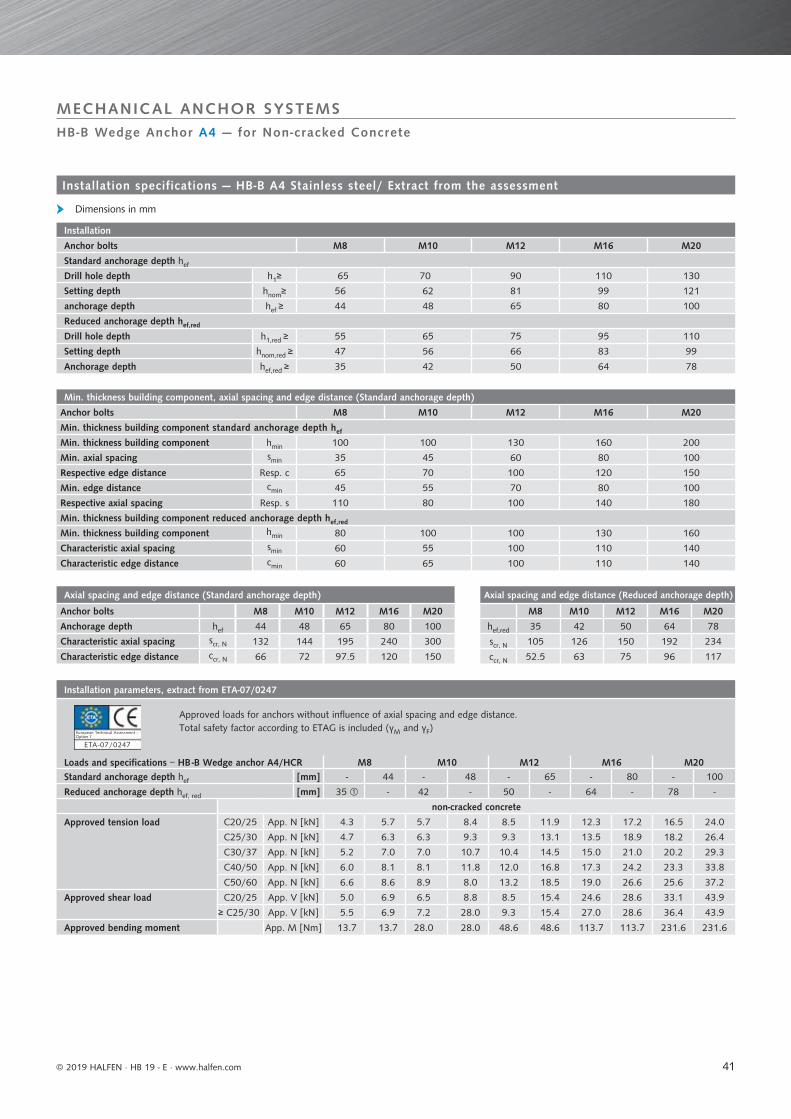
41
Axial spacing and edge distance (Standard anchorage depth)
Anchor bolts M8 M10 M12 M16 M20
Anchorage depth hef 44 48 65 80 100
Characteristic axial spacing scr, N 132 144 195 240 300
Characteristic edge distance ccr, N 66 72 97.5 120 150
Axial spacing and edge distance (Reduced anchorage depth)
M8 M10 M12 M16 M20
hef,red 35 42 50 64 78
scr, N 105 126 150 192 234
ccr, N 52.5 63 75 96 117
Installation parameters, extract from ETA-07/0247
Approved loads for anchors without influence of axial spacing and edge distance.Total safety factor according to ETAG is included (γM and γF)
Loads and specifications − HB -B Wedge anchor A4/HCR M8 M10 M12 M16 M20Standard anchorage depth hef [mm] - 44 - 48 - 65 - 80 - 100
Reduced anchorage depth hef, red [mm] 35 - 42 - 50 - 64 - 78 -
non-cracked concrete
Approved tension load C20/25 App. N [kN] 4.3 5.7 5.7 8.4 8.5 11.9 12.3 17.2 16.5 24.0
C25/30 App. N [kN] 4.7 6.3 6.3 9.3 9.3 13.1 13.5 18.9 18.2 26.4
C30/37 App. N [kN] 5.2 7.0 7.0 10.7 10.4 14.5 15.0 21.0 20.2 29.3
C40/50 App. N [kN] 6.0 8.1 8.1 11.8 12.0 16.8 17.3 24.2 23.3 33.8
C50/60 App. N [kN] 6.6 8.6 8.9 8.0 13.2 18.5 19.0 26.6 25.6 37.2
Approved shear load C20/25 App. V [kN] 5.0 6.9 6.5 8.8 8.5 15.4 24.6 28.6 33.1 43.9
≥ C25/30 App. V [kN] 5.5 6.9 7.2 28.0 9.3 15.4 27.0 28.6 36.4 43.9
Approved bending moment App. M [Nm] 13.7 13.7 28.0 28.0 48.6 48.6 113.7 113.7 231.6 231.6
Min. thickness building component, axial spacing and edge distance (Standard anchorage depth)
Anchor bolts M8 M10 M12 M16 M20
Min. thickness building component standard anchorage depth hef
Min. thickness building component hmin 100 100 130 160 200
Min. axial spacing smin 35 45 60 80 100
Respective edge distance Resp. c 65 70 100 120 150
Min. edge distance cmin 45 55 70 80 100
Respective axial spacing Resp. s 110 80 100 140 180
Min. thickness building component reduced anchorage depth hef,red
Min. thickness building component hmin 80 100 100 130 160
Characteristic axial spacing smin 60 55 100 110 140
Characteristic edge distance cmin 60 65 100 110 140
Installation
Anchor bolts M8 M10 M12 M16 M20
Standard anchorage depth hef
Drill hole depth h1≥ 65 70 90 110 130
Setting depth hnom≥ 56 62 81 99 121
anchorage depth hef ≥ 44 48 65 80 100
Reduced anchorage depth hef,red
Drill hole depth h1,red ≥ 55 65 75 95 110
Setting depth hnom,red ≥ 47 56 66 83 99
Anchorage depth hef,red ≥ 35 42 50 64 78
© 2019 HALFEN · HB 19 - E · www.halfen.com
HB-B Wedge Anchor A4 — for Non-cracked Concrete
MECHANICAL ANCHOR SYSTEMS
Installation specifications — HB-B A4 Stainless steel/ Extract from the assessment
Dimensions in mm
Option 7
ETA -07/0247
European Technical Assessment -
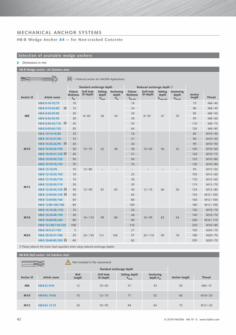
42
HB -B Wedge anchor – A4 Stainless steel
Standard anchorage depth Reduced anchorage depth
Fixture thickness
tfix
Drill hole Ø×depth
Setting depthhnom
Anchoringdepth
hef
Fixture thickness
tfix,red
Drill hole Ø×depth
Setting depthhnom,red
Anchoringdepthhef,red
Anchor Ø Article nameAnchor length Thread
M8
HB-B 8-10-19/75 10
8 × 65 56 44
19
8 × 55 47 35
75 M8 × 40
HB-B 8-15-24/80 15 24 80 M8 × 45
HB-B 8-20-29/85 20 29 85 M8 × 50
HB-B 8-30-39/95 30 39 95 M8 × 60
HB-B 8-45-54/110 45 54 110 M8 × 75
HB-B 8-55-64/120 55 64 120 M8 × 85
M10
HB-B 10-10-16/85 10
10 × 70 62 48
16
10 × 65 56 42
85 M10 × 40
HB-B 10-15-21/90 15 21 90 M10 × 45
HB-B 10-20-26/95 20 26 95 M10 × 50
HB-B 10-30-36/105 30 36 105 M10 × 60
HB-B 10-45-51/120 45 51 120 M10 × 75
HB-B 10-50-56/125 50 56 125 M10 × 80
HB-B 10-70-76/145 70 76 145 M10 × 80
M12
HB-B 12-10/95 10 12 × 80 – – – – – – 95 M12 × 50
HB-B 12-10-25/105 10
12 × 90 81 65
25
12 × 75 66 50
105 M12 × 60
HB-B 12-15-30/110 15 30 110 M12 × 65
HB-B 12-20-35/115 20 35 115 M12 × 70
HB-B 12-30-45/125 30 45 125 M12 × 80
HB-B 12-50-65/145 50 65 145 M12 × 100
HB-B 12-65-80/160 65 80 160 M12 × 100
HB-B 12-85-100/180 85 100 180 M12 × 100
M16
HB-B 16-10-28-/130 10
16 × 110 99 80
26
16 × 95 83 64
130 M16 × 70
HB-B 16-30-48/150 30 46 150 M16 × 70
HB-B 16-80-98/200 80 96 200 M16 × 110
HB-B 16-100-118/220 100 116 220 M16 × 80
M20
HB-B 20-5-27/150 5
20 × 130 121 100
27
20 × 110 99 78
150 M20 × 70
HB-B 20-35-57/180 35 57 180 M20 × 70
HB-B 20-60-82/205 60 82 205 M20 × 70
HB -B-IG Bolt anchor – A4 Stainless steel
Standard anchorage depth
Bolt length
Drill hole Ø×depth
Setting depthhnom
Anchoringdepth hefAnchor Ø Article name Anchor length Thread
M8 HB-B-IG 8-50 12 10 × 65 57 43 50 M8 × 15
M10 HB-B-IG 10-60 15 12 × 75 71 52 60 M10 × 20
M12 HB-B-IG 12-75 20 16 × 95 84 64 75 M12 × 26
© 2019 HALFEN · HB 19 - E ⋅ www.halfen.com
HB-B Wedge Anchor A4 — for Non-cracked Concrete
MECHANICAL ANCHOR SYSTEMS
Select ion of ava i lab le wedge anchors
Dimensions in mm
Please observe the lower load capacities when using reduced anchorage depths.
= Preferred anchor for HALFEN Applications
Not included in the assessment

43
Air gun / Blow-out pump
Article name Suitable for drill holes Ø [mm]
HB-VM-ABP 22-26
HB-VM-AP 360 8-35
HB-VM-SH Prefo sleeve
Article name Ø mm Suitable for [mm] Setting depth [mm]
HB-VM-SH 16 × 85 M8/M10 80
HB-VM-SH 20 × 85 M12/M16 80
HB-VM-SH 20 × 130 M12/M16 130
HB -RB – Cleaning brush
Article name Drill hole Suitable for HB -Ø mm
HB -RB 10 10 VMZ, V, VMU M8
HB -RB 12 12 VMZ, V, VMU M10
HB -RB 14 14 VMZ, V, VMU M12
HB -RB 18 18 VMZ, V, VMU M16
HB -RB 22 22 VMZ 115, M20
HB -RB 24 24 VMZ, VMU M20
HB -RB 26 26 V M20, VMZ, VMU M24
HB -RB 28 28 V M24
HB -RB-H – Cleaning brush with wood handle
Article name Brush Suitable for drill holeØ mm Ø mm
HB -RB-H 18 18 10-16
Single cartridges are also available. 280 ml cartridge can be used with standard dispensers;
two mixer nozzles are supplied with each 280 ml cartridge. One nozzle is supplied with these cartridges.
HB -VMU/ VMZ – Injection system
Article name Contents[ml]
Number of cartridges in standard delivery
Cartridges
HB-VMZ 280 280 12
HB-VMZ 420 420 12
HB-VMU plus 280 280 12
HB-VMU plus 410 410 12
Nozzles, screw-on mixer nozzles
HB -VM-(Profi) Dispenser
Article name
HB-VM-P 345 Dispenser suitable for standard silicone cartridgesHB-VM-P 345 Profi dispenser
HB-VM-P 420 Profi dispenser suitable for 410 ml and 420 ml cartridges
© 2019 HALFEN · HB 19 - E · www.halfen.com
Accessories
HB ANCHORS
Accessor ies
Accessories for cleaning drill holes
HB-VM-SH Prefo sleeve
HB -VM Dispenser
HB -VMU plus / HB -VMZ Injections system
Cleaning brush with wood handle
Cleaning brush
Blowout pump
Airgun
Prefo sleeve
U p u / jec o y e

44 © 2019 HALFEN · HB 19 - E · www.halfen.com
ServiceHALFEN ANCHOR SYSTEMS
Fire Resistance TablesHALFEN HB-BZ Anchor bolts are fi re resistance tested. Complete test reports can be provided on request.See page 46
We off er a comprehensive customer service.
Contact HALFEN directly for competent technical support for all your projects; no project is too small, no project is too large!
Calculation software Used for quick verification of load-bearing capacities of various standard anchor layouts.See page 45
Support We provide telephone support. The HALFEN support team is available to help you in project details or to provide comprehensive project support. See page 47 for contact information
DesignHALFEN designs and calculates fixing solutions for complete projects; for brickwork cladding or natural stone façades
Fire tested
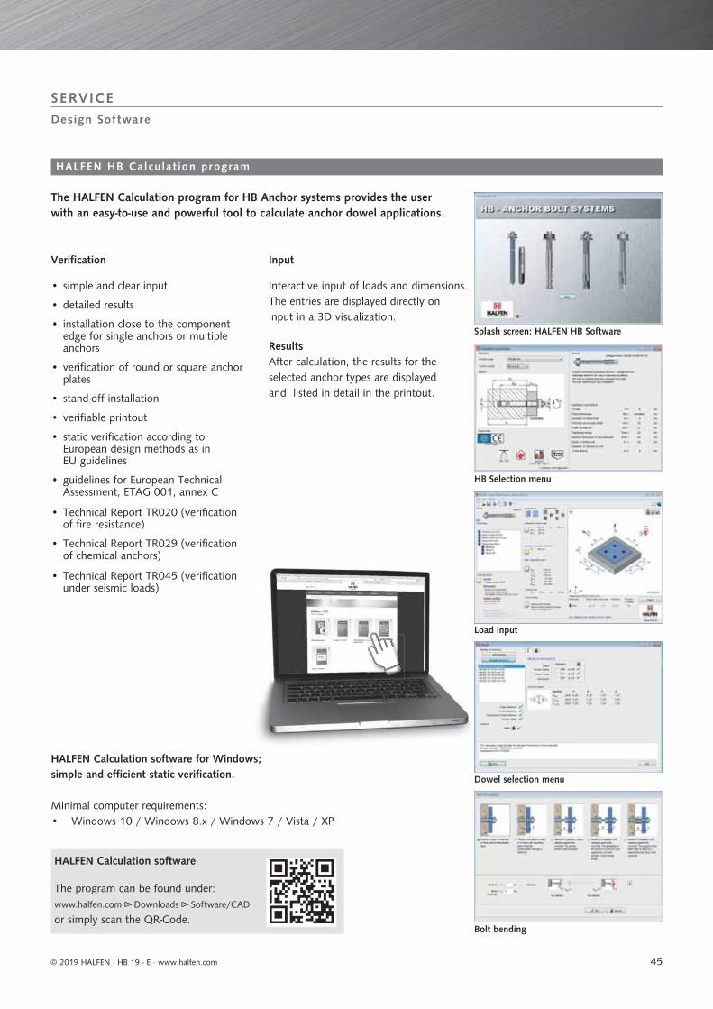
45© 2019 HALFEN · HB 19 - E · www.halfen.com
HALFEN Calculation software
The program can be found under: www.halfen.com ►► Downloads ►► Software/CAD
or simply scan the QR-Code.
The HALFEN Calculation program for HB Anchor systems provides the user with an easy-to-use and powerful tool to calculate anchor dowel applications.
Design Sof tware
SERVICE
HALFEN HB Calcu lat ion program
Splash screen: HALFEN HB Software
Bolt bending
Load input
Dowel selection menu
HB Selection menu
HALFEN Calculation software for Windows; simple and efficient static verification.
Minimal computer requirements: • Windows 10 / Windows 8.x / Windows 7 / Vista / XP
• simple and clear input
• detailed results
• installation close to the component edge for single anchors or multiple anchors
• verification of round or square anchor plates
• stand-off installation
• verifiable printout
• static verification according toEuropean design methods as in EU guidelines
• guidelines for European Technical Assessment, ETAG 001, annex C
• Technical Report TR020 (verification of fire resistance)
• Technical Report TR029 (verificationof chemical anchors)
• Technical Report TR045 (verification under seismic loads)
Interactive input of loads and dimensions. The entries are displayed directly on input in a 3D visualization.
ResultsAfter calculation, the results for the selected anchor types are displayed and listed in detail in the printout.
Verification Input

46
Anchor systems IBMB* report Bolt sizeMaximum tension load [kN] when subjected to fire
according to DIN 4102-2 for fire resistant class.
F 30 F 60 F 90 F 120HB -BZ Wedge anchor galvanized steel
ETA-99/0010
M8 hef,red/hef,std 1.25/1.25 1.10/1.10 0.80/0.80 0.60/0.70
M10 hef,red/hef,std 1.82/2.25 1.82/1.90 1.30/1.40 1.00/1.20
M12 hef,red/hef,std 3.18/4.00 3.00/3.00 1.90/2.40 1.30/2.20
M16 hef,red/hef,std 4.72/6.25 4.72/5.60 3.50/4.40 2.50/4.00
M20 hef,std 9.00 8.20 6.90 6.30
M24 hef,std 11.10 11.10 10.00 8.88
HB -BZ Wedge anchor A4 Stainless steel/ HCR Stainless steel grade 1.4529
ETA-99/0010
M8 hef,red/hef,std 1.25/1.25 1.25/1.25 1.25/1.25 1.00/1.00
M10 hef,red/hef,std 1.82/2.25 1.82/2.25 1.82/2.25 1.46/1.80
M12 hef,red/hef,std 3.18/4.00 3.18/4.00 3.18/4.00 2.55/3.20
M16 hef,red/hef,std 4.72/6.25 4.72/6.25 4.72/6.25 3.77/5.00
M20 hef,std 9.00 9.00 9.00 7.20
© 2019 HALFEN · HB 19 - E ⋅ www.halfen.com
Fire Resistant Anchor Systems
HB ANCHOR SYSTEMS
Fire tested in accordance with the Standard time temperaturecurve (ISO 834, DIN EN 1363-1: 1999-10, DIN 4102-2: 1977-09) in the cracked tension zone (concrete), exposed to open fl ames, without insulation or protective coatings.
*IBMB = (German) Institute of Building Materials, Concrete Construction and Fire Safety
Fire tested
F i re res is tant f ix ings

www.dnvgl.com
NOTES REGARDING THIS CATALOGUETechnical and design changes reserved. The information in this publication is based on state-of-the-art technology at the time of publication. We reserve the right to make technical and design changes at any time. HALFEN GmbH shall not accept liability for the accuracy of the information in this publication or for any printing errors.
The HALFEN GmbH subsidiaries in Germany, France, the Netherlands, Austria, Poland, Switzerland and the Czech Republic are Quality Management certified according to ISO 9001:2015, Certificate no. 202384-2016-AQ-GER-DAkkS.
Austria HALFEN Gesellschaft m.b.H.Leonard-Bernstein-Str. 101220 Wien
Phone: +43 - 1 - 259 6770 E-Mail: [email protected]: www.halfen.at
Belgium / Luxembourg HALFEN N.V.Borkelstraat 1312900 Schoten
Phone: +32 - 3 - 658 07 20E-Mail: [email protected]: www.halfen.be
Fax: +32 - 3 - 658 15 33
China HALFEN Construction Accessories Distribution Co.Ltd.Room 601 Tower D, Vantone CentreNo. A6 Chao Yang Men Wai StreetChaoyang District Beijing · P.R. China 100020
Phone: +86 - 10 5907 3200E-Mail: [email protected]: www.halfen.cn
Fax: +86 - 10 5907 3218
Czech Republic HALFEN s.r.o.Business Center ŠafránkovaŠafránkova 1238/1155 00 Praha 5
Phone: +420 - 311 - 690 060E-Mail: [email protected]: www.halfen.cz
Fax: +420 - 235 - 314 308
France HALFEN S.A.S.18, rue Goubet75019 Paris
Phone: +33 - 1 - 445231 00E-Mail: [email protected]: www.halfen.fr
Fax: +33 - 1 - 445231 52
Germany HALFEN Vertriebsgesellschaft mbHLiebigstr. 14 40764 Langenfeld
Phone: +49 - 2173 - 970 - 0E-Mail: [email protected]: www.halfen.de
Fax: +49 - 2173 - 970 225
Italy HALFEN S.r.l. Soc. UnipersonaleVia F.lli Bronzetti N° 2824124 Bergamo
Phone: +39 - 035 - 0760711E-Mail: [email protected]: www.halfen.it
Fax: +39 - 035 - 0760799
Netherlands HALFEN b.v.Oostermaat 37623 CS Borne
Phone: +31 - 74-267 14 49E-Mail: [email protected]: www.halfen.nl
Fax: +31 - 74-267 26 59
Norway HALFEN ASPostboks 20804095 Stavanger
Phone: +47 - 51 82 34 00E-Mail: [email protected]: www.halfen.no
Poland HALFEN Sp. z o.o.Ul. Obornicka 28760-691 Poznan
Phone: +48 - 61 - 622 14 14E-Mail: [email protected]: www.halfen.pl
Fax: +48 - 61 - 622 14 15
Spain HALFEN IBERICA, S.L.Polígono Industrial Santa Ana c/ Ignacio Zuloaga 2028522 Rivas-Vaciamadrid
Phone: +34 - 91 632 18 40E-Mail: [email protected]: www.halfen.es
Fax: +34 - 91 633 42 57
Sweden Halfen ABVädursgatan 5412 50 Göteborg
Phone: +46 - 31 - 98 58 00E-Mail: [email protected]: www.halfen.se
Fax: +46 - 31 - 98 58 01
Switzerland HALFEN Swiss AGHertistrasse 25 8304 Wallisellen
Phone: +41 - 44 - 849 78 78E-Mail: [email protected]: www.halfen.ch
Fax: +41 - 44 - 849 78 79
United Kingdom /Ireland
HALFEN Ltd.A1/A2 Portland CloseHoughton Regis LU5 5AW
Phone: +44 - 1582 - 47 03 00E-Mail: [email protected]: www.halfen.co.uk
Fax: +44 - 1582 - 47 03 04
United States of America HALFEN USA Inc. PO Box 18687 San Antonio TX 78218
Phone: +1 800.423.91 40E-Mail: [email protected]: www.halfenusa.com
Fax: +1 877.683.4910
For countries not listed HALFEN International
HALFEN International GmbHLiebigstr. 14 40764 Langenfeld / Germany
Phone: +49 - 2173 - 970 - 0 E-Mail: [email protected]: www.halfen.com
Fax: +49 - 2173 - 970 - 849
CONTACT HALFEN WORLDWIDE
HALFEN is represented by subsidiaries in the following countries, please contact us!

© 2
019
HA
LFEN
Gm
bH, G
erm
any
appl
ies
also
to
copy
ing
in e
xtra
cts.
B - 0
23-E
- 02
/19
02/
19