h. prin, f. savary, d. duarte ramos, l. grand- clement, c. mucher, a. temporal
TRANSCRIPT
Design of the 6 m cold masses assembly
H. Prin, F. Savary, D. Duarte Ramos, L. Grand-Clement, C. Mucher, A. Temporal
Click here to add footer 2
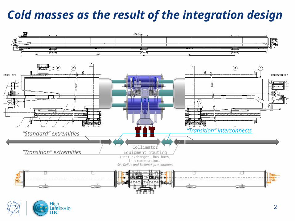
Cold masses as the result of the integration design
CollimatorEquipment routing
(Heat exchanger, bus bars,instrumentation…)
See Delio’s and Stefano’s presentations
“Standard” extremities
“Transition” extremities
“Transition” interconnects
Click here to add footer 3
Out line• Cold masses main parameters• “Standard” extremities• “Transition” extremities• Interconnections and interfaces• Standardization• Components• Tooling• Conclusion

Click here to add footer 4
Cold masses main parametersCold Mass: leak tight envelope surrounding one or more superconducting magnets which acts as a helium pressure vessel and provide the mechanical rigidity to align the magnetic element(s). It is composed of two welded half-shells closed by two end covers in the extremities.
Two type of cold masses:• Identical lengths 6252mm• LMBH1 contains MBH +
2MCDO• LMBH2 contains MBH + 2MCS• MBH active part 5799mm• MBH impreg. coil 5573mm• MBH coils 5417mm• MBH mag length 5307mm
Common components:• MBH magnet• Welded half shells• Cold bore tubes• Heat exchanger tube• Supports
Distinctive components:• Bus bars routing and connections• End covers and interfaces• Diode• Instrumentation• Multipole Correctors
LMBH1
LMBH2

Click here to add footer 5
“Standard” extremities
• MB end covers on both sides without any modification
• Between end covers and the end plates, the configuration remains almost the same as for a MBA magnet (see next presentation)
• the two apertures are not connected in series inside the first cold mass, additional bus bars have to connect the second cold mass (see next presentation)
• Main bus bars routing is identical to the MBA configuration
• Recent developments driven on MB2387 to connect 600A bus bars for “CLIQ test” to the internal splices could be applied for the trim
• Instrumentation capillary (IFS) may have to be revised depending on the wiring

Click here to add footer 6
Possible design improvements
• Diode bolted connection
• Proximity between the bus bar lyre and the corrector support
• “Spiders” (bus bars spacers and
centring) design and materials
• Internal splices redesign?• Additional instrumentation?
“Standard” extremities
Click here to add footer 7
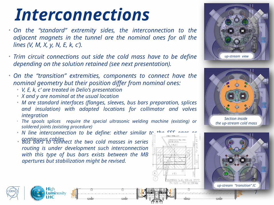
Interconnections• On the “standard” extremity sides, the interconnection to the
adjacent magnets in the tunnel are the nominal ones for all the lines (V, M, X, y, N, E, k, c’).
• Trim circuit connections out side the cold mass have to be define depending on the solution retained (see next presentation).
• On the “transition” extremities, components to connect have the nominal geometry but their position differ from nominal ones:
• V, E, k, c’ are treated in Delio’s presentation• X and y are nominal at the usual location• M are standard interfaces (flanges, sleeves, bus bars preparation, splices
and insulation) with adapted locations for collimator and valves integration• The spools splices require the special ultrasonic welding machine (existing) or
soldered joints (existing procedure)• N line interconnection to be define: either similar to the SSS ones or
continuous cables
up-stream view
Section inside the up-stream cold mass
up-stream “transition” IC
• Bus bars to connect the two cold masses in series routing is under development such interconnection with this type of bus bars exists between the MB apertures but stabilization might be revised.

Click here to add footer 8
“Transition” extremities
Bus bars design under study:• Usual radius and twist used in
the “standard” dipole lyras• Bending radius and twist to be
developed
Typical MB splices (between poles and apertures), simpler than the ones in the standard end cover
Bus bars detailed routing to connect apertures in series is under study (global scheme in the next presentation).
Typical MB insulation pieces
N line routing under study to maximise elbows radius to ease cables insertion
Click here to add footer 9
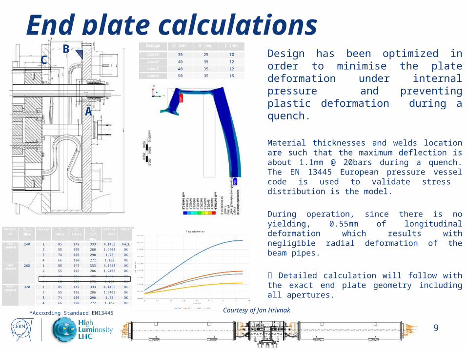
End plate calculationsDesign has been optimized in order to minimise the plate deformation under internal pressure and preventing plastic deformation during a quench.
Material thicknesses and welds location are such that the maximum deflection is about 1.1mm @ 20bars during a quench. The EN 13445 European pressure vessel code is used to validate stress distribution is the model.
During operation, since there is no yielding, 0.55mm of longitudinal deformation which results with negligible radial deformation of the beam pipes.
Detailed calculation will follow with the exact end plate geometry including all apertures.
Material Rp 0,2
[MPa]Design fm [MPa] fl [MPa] fg+ fm+fb
[MPa]Deform.
[mm]Check*
304L(EN10088)
240 1 85 149 333 4.1453 FAIL
2 55 105 286 1.9403 OK
3 74 106 290 1.75 OK
4 66 100 272 1.102 OK
316L(EN10088)
260 1 85 149 333 4.1453 OK
2 55 105 286 1.9403 OK
3 74 106 290 1.75 OK
4 66 100 272 1.102 OK
316LN(EN10088)
320 1 85 149 333 4.1453 OK
2 55 105 286 1.9403 OK
3 74 106 290 1.75 OK
4 66 100 272 1.102 OK
Design A [mm] B [mm] C [mm]
Case1 30 25 10
Case2 40 35 12
Case3 40 35 12
Case4 50 35 15
A
BC
Courtesy of Jan Hrivnak*According Standard EN13445

Click here to add footer 10
StandardizationAs far as possible existing components and procedures are used in the proposed design:
Cold masses assembly• Main components are identical or derived from the ones used in the existing MB or SSS
• Assembly procedures can be easily adapted from existing ones
• Only one cold mass type per position independently of the variety of magnet that has to be substituted (no MBA or MBB type)
Cold tests• A pair of assemblies to substitute a MB dipole could easily be connected to the exiting SM18 test bench
with standard components and procedures
• Trim connection has to be studied since there is none at present, spool circuits could be used in case
• Testing each assembly remains possible with work either on the bench or the cold mass interfaces
Installation in the machine• Interconnections in the “standard” extremities remain regular as everywhere else in the LHC arcs;
• Interconnections in the “transition” extremities uses regular components design located in unusual location but with major efforts to keep them accessible
• Usual tooling and procedures are applicable (splice soldering, shunt soldering, insulation, welding, cutting)

Click here to add footer 11
Components Magnet yokes and related components End plates Stainless shells have to ordered, formed and machined
difficulties to order 316LN for the moment experienced companies are already identified
Connexion and electrical insulation pieces Welding flanges and flares Cold mass supports MCS and MCDO multipole correctors Diode Standard dished end covers Bellows and hoses N-Line Bus bars
Hollow copper and sc cable available (spare stock to be refurbished) Proven knowhow in the LMF busbar team
Insulated cold bore tubes Ø50/53 Stainless steel tubes available for the requiered lengths Insulation proven knowhow in the LMF busbar team
Heat exchanger tubes Copper tube and Cu/SST transition in stock BE to be done
Welding rings Flat end covers
Availability for LS2 deadline
Click here to add footer 12
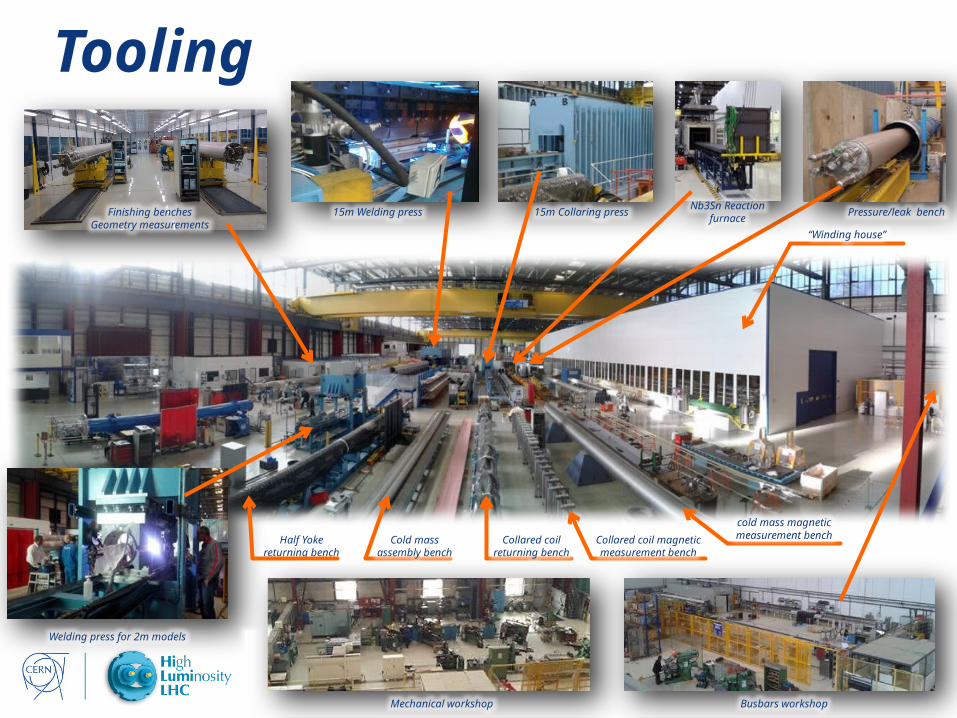
Tooling
cold mass magnetic measurement benchCollared coil magnetic
measurement benchCollared coil
returning benchCold mass
assembly benchHalf Yoke
returning bench
Welding press for 2m models
Pressure/leak bench
“Winding house”
15m Collaring pressFinishing benchesGeometry measurements
15m Welding pressNb3Sn Reaction
furnace
Mechanical workshop Busbars workshop

Click here to add footer 13
ToolingOngoing developments to replace STT by TIG welding technology
• About 300MPa azimuthal stress obtained in the second prototype shells after welding
• Process more tolerant in terms of geometry• Quality of the weld
Courtesy of F. Lackner
• 8 passes for 12mm thickness to be adapted for 15mm• Backing strip necessary for gap > 1.5mm
Click here to add footer 14
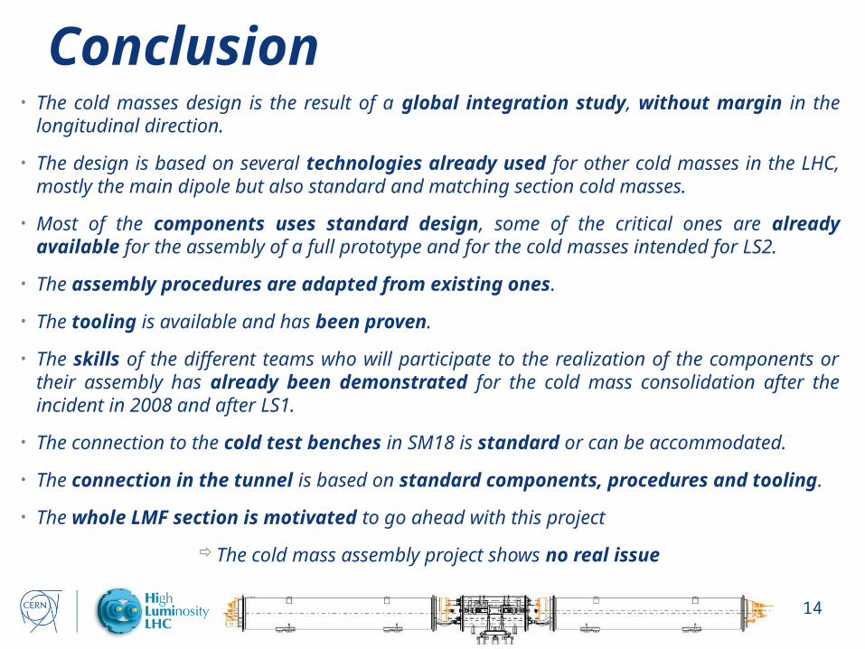
Conclusion• The cold masses design is the result of a global integration study, without margin in the
longitudinal direction.
• The design is based on several technologies already used for other cold masses in the LHC, mostly the main dipole but also standard and matching section cold masses.
• Most of the components uses standard design, some of the critical ones are already available for the assembly of a full prototype and for the cold masses intended for LS2.
• The assembly procedures are adapted from existing ones.
• The tooling is available and has been proven.
• The skills of the different teams who will participate to the realization of the components or their assembly has already been demonstrated for the cold mass consolidation after the incident in 2008 and after LS1.
• The connection to the cold test benches in SM18 is standard or can be accommodated.
• The connection in the tunnel is based on standard components, procedures and tooling.
• The whole LMF section is motivated to go ahead with this project
The cold mass assembly project shows no real issue

Click here to add footer 15
Spare slides
Click here to add footer 16
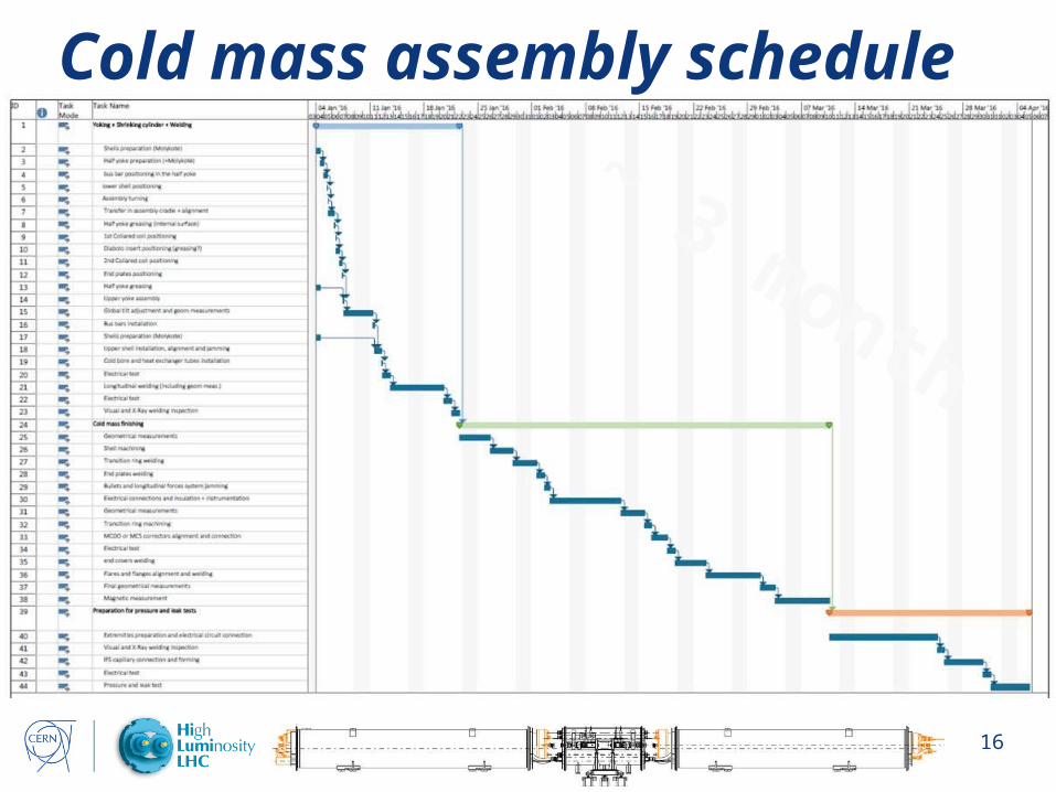
Cold mass assembly schedule
~ 3 month

Click here to add footer 17
Design of the instrumented bullet gaugesCourtesy of A. Temporal

Click here to add footer 18
Trim cables connection
Click here to add footer 19
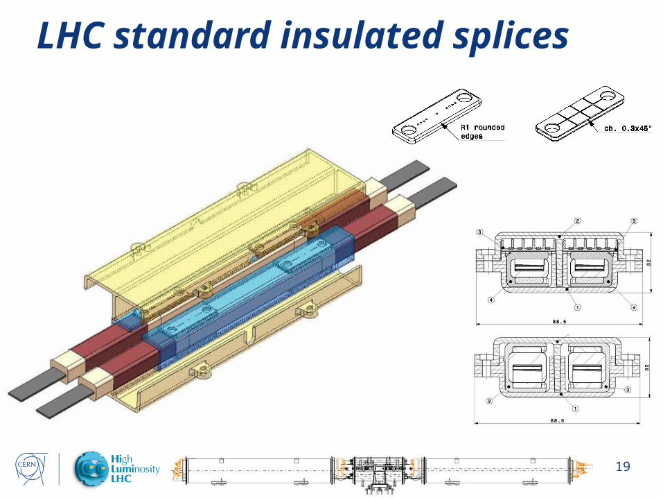
LHC standard insulated splices