h-1a - h-4 · center or martin conveyor division distributor for a recommen-dation. types ... 10....
TRANSCRIPT

H-116
BucketElevators
SECTION VI
*MORE

H-117
Safety
Safety must be considered a basic factor in machinery operation at all times. Most accidents are the result of carelessness or negligence. The fol-lowing safety instructions are basic guidelines and should be considered as minimum provisions. Additional information shall be obtained by thepurchaser from other sources, including the American Society of Mechanical Engineers, Standard ANSI B20.1, Standard ANSI B15.1; StandardANSI Z244.
It is the responsibility of the contractor, installer, owner and user to install, maintain and operate the bucket elevator and elevator assemblies manu-factured and supplied by Martin Conveyor Division, in such a manner as to comply with the Williams-Steiger Occupational Safety and Health Actand with all state and local laws and ordinances and the American National Standards Institute Safety Code.
Precautions:1. Maintain a safety training and safety equipment operation/maintenance program for all employees.2. Bucket elevators shall not be operated unless the elevator housing completely encloses the elevator moving elements and power transmission
guards are in place. If the elevator is to be opened for inspection, cleaning or observation, the motor driving the conveyor is to belocked out electrically in such a manner that it cannot be restarted by anyone, however remote from the area, unless the elevatorhousing has been closed and all other guards are in place.
3. If the elevator must have an open housing as a condition of its use and application, the entire elevator is then to be guarded by a railing orfence.
4. RUGGED gratings may be used where necessary. If the distance between the grating moving elements is less than 4 inches, the grating open-ing must not exceed 1⁄2 inch by 2 inches. In all cases the openings shall be restrictive to keep any part of the body or clothing from coming incontact with moving parts of the equipment. SOLID COVERS should be used at all points and must be designed and installed so that personnelwill not be exposed to accidental contact with any moving parts of the equipment.
5. All rotating equipment such as guards, drives, gears, shafts and couplings must be guarded by the purchaser/owner as required by applicablelaws, standards and good practice.
6. SAFETY DEVICES AND CONTROLS must be purchased and provided by the purchaser/owner as required by applicable laws, standards andgood practices.
7. Practice good housekeeping at all times and maintain good lighting around all equipment.8. Keep all operating personnel advised of the location and operation of all emergency controls and devices. Clear access to these controls and
devices must be maintained.9. Frequent inspections of these controls and devices, covers, guards and equipment to ensure proper working order and correct positioning.
10. Do not walk on elevator covers, gratings or guards.11. Do not poke or prod material in the elevator.12. Do not place hands, feet or any part of the body or clothing in the elevator or opening.13. Do not overload elevator or attempt to use it for other than its intended use.14. Inlet and discharge openings shall be connected to other equipment in order to completely enclose the moving elements of the elevator.15. Before power is connected to the drive a pre-start up check shall be performed to ensure the equipment and area are safe for operation and all
guards are in place and secure.16. Bucket Elevators are not manufactured or designed to handle materials that are hazardous to personnel unless specially designed. These
materials which are hazardous include those that are explosive, flammable, toxic or otherwise dangerous to personnel. Elevators may bedesigned to handle these materials. Elevators are not manufactured or designed to comply with local, state or federal codes for unfired pres-sure vessels. If hazardous materials are to be conveyed or if the elevator is to be subjected to internal or external pressure, ConveyorDivision should be consulted prior to any modifications.
17. Removal of backstop may cause unexpected machine movement. Remove or block all external loadsbefore servicing unit. Failure to observe these precautions could result in bodily injury.
All equipment shall be checked for damage immediately upon arrival. Do not attempt to install a damageditem or elevator.
All bucket elevators shop assembled by Martin Conveyor Division, have warning labels affixed in many eas-ily seen locations. If the equipment exterior is painted, coated or altered in any way or if the material con-veyed is in excess of 175°F or if a change in the original intended use of the equipment is considered, thefactory shall be consulted before modifications are made. Additional stickers are available upon request.
CHS930001
Exposed moving �parts can cause �severe injury��LOCK OUT POWER�before removing�guard
CHR930001CHS930001(5” Wide x 2 1/2” High)
CVS930012(3” Wide x 6” High)
H-118
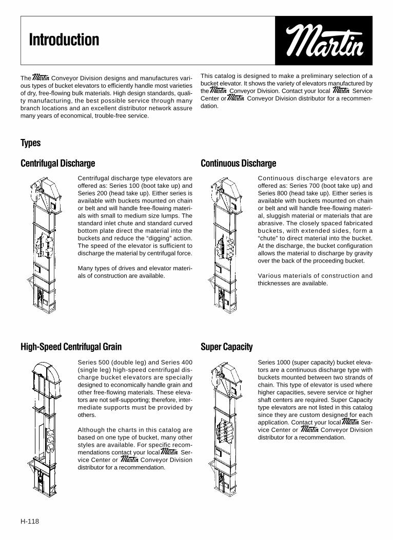
Introduction
The Martin Conveyor Division designs and manufactures vari-ous types of bucket elevators to efficiently handle most varietiesof dry, free-flowing bulk materials. High design standards, quali-ty manufacturing, the best possible service through manybranch locations and an excellent distributor network assuremany years of economical, trouble-free service.
This catalog is designed to make a preliminary selection of abucket elevator. It shows the variety of elevators manufactured bythe Martin Conveyor Division. Contact your local Martin ServiceCenter or Martin Conveyor Division distributor for a recommen-dation.
Types
Centrifugal Discharge Continuous DischargeCentrifugal discharge type elevators areoffered as: Series 100 (boot take up) andSeries 200 (head take up). Either series isavailable with buckets mounted on chainor belt and will handle free-flowing materi-als with small to medium size lumps. Thestandard inlet chute and standard curvedbottom plate direct the material into thebuckets and reduce the “digging” action.The speed of the elevator is sufficient todischarge the material by centrifugal force.
Many types of drives and elevator materi-als of construction are available.
Continuous discharge elevators areoffered as: Series 700 (boot take up) andSeries 800 (head take up). Either series isavailable with buckets mounted on chainor belt and will handle free-flowing materi-al, sluggish material or materials that areabrasive. The closely spaced fabricatedbuckets, with extended sides, form a“chute” to direct material into the bucket.At the discharge, the bucket configurationallows the material to discharge by gravityover the back of the proceeding bucket.
Various materials of construction andthicknesses are available.
High-Speed Centrifugal Grain Super CapacitySeries 500 (double leg) and Series 400(single leg) high-speed centrifugal dis-charge bucket elevators are speciallydesigned to economically handle grain andother free-flowing materials. These eleva-tors are not self-supporting; therefore, inter-mediate supports must be provided byothers.
Although the charts in this catalog arebased on one type of bucket, many otherstyles are available. For specific recom-mendations contact your local Martin Ser-vice Center or Martin Conveyor Divisiondistributor for a recommendation.
Series 1000 (super capacity) bucket eleva-tors are a continuous discharge type withbuckets mounted between two strands ofchain. This type of elevator is used wherehigher capacities, severe service or highershaft centers are required. Super Capacitytype elevators are not listed in this catalogsince they are custom designed for eachapplication. Contact your local Martin Ser-vice Center or Martin Conveyor Divisiondistributor for a recommendation.
H-119
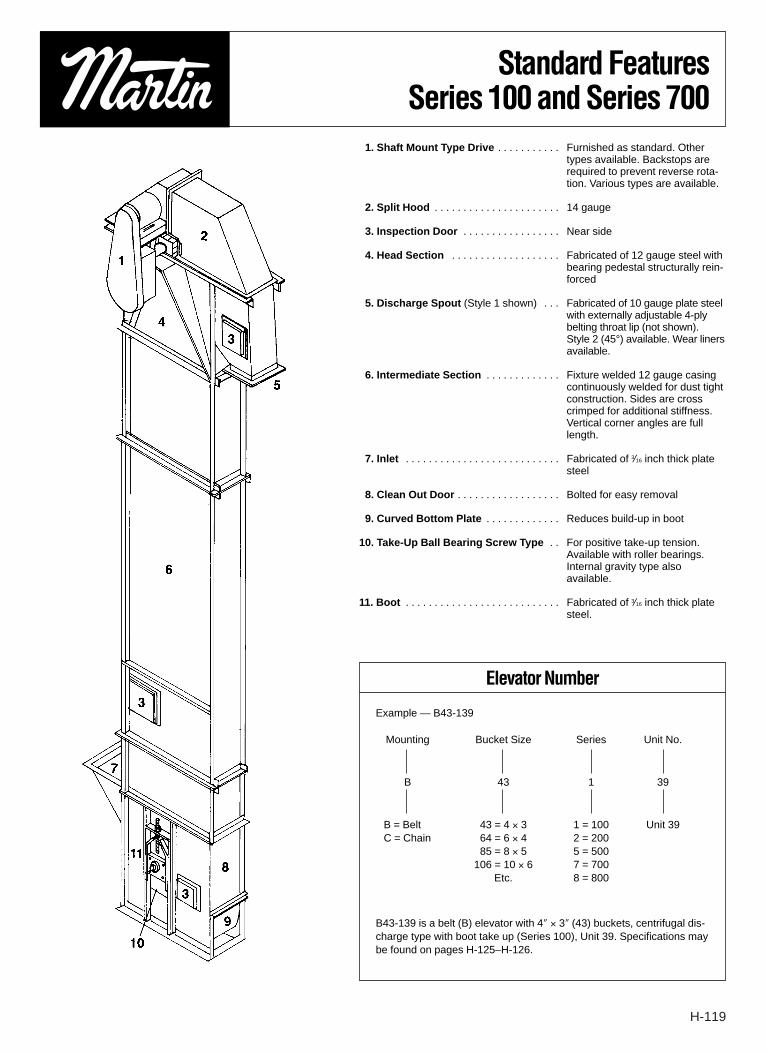
Standard FeaturesSeries 100 and Series 700
1. Shaft Mount Type Drive . . . . . . . . . . . Furnished as standard. Othertypes available. Backstops arerequired to prevent reverse rota-tion. Various types are available.
2. Split Hood . . . . . . . . . . . . . . . . . . . . . . 14 gauge
3. Inspection Door . . . . . . . . . . . . . . . . . Near side
4. Head Section . . . . . . . . . . . . . . . . . . . Fabricated of 12 gauge steel withbearing pedestal structurally rein-forced
5. Discharge Spout (Style 1 shown) . . . Fabricated of 10 gauge plate steelwith externally adjustable 4-plybelting throat lip (not shown). Style 2 (45°) available. Wear linersavailable.
6. Intermediate Section . . . . . . . . . . . . . Fixture welded 12 gauge casingcontinuously welded for dust tightconstruction. Sides are crosscrimped for additional stiffness.Vertical corner angles are fulllength.
7. Inlet . . . . . . . . . . . . . . . . . . . . . . . . . . . Fabricated of 3⁄16 inch thick platesteel
8. Clean Out Door . . . . . . . . . . . . . . . . . . Bolted for easy removal
9. Curved Bottom Plate . . . . . . . . . . . . . Reduces build-up in boot
10. Take-Up Ball Bearing Screw Type . . For positive take-up tension.Available with roller bearings.Internal gravity type alsoavailable.
11. Boot . . . . . . . . . . . . . . . . . . . . . . . . . . . Fabricated of 3⁄16 inch thick platesteel.
Elevator Number
Example — B43-139
Mounting Bucket Size Series Unit No.
B 43 1 39
B = Belt 43 = 4 × 3 1 = 100 Unit 39C = Chain 64 = 6 × 4 2 = 200
85 = 8 × 5 5 = 500106 = 10 × 6 7 = 700
Etc. 8 = 800
B43-139 is a belt (B) elevator with 4″ × 3″ (43) buckets, centrifugal dis-charge type with boot take up (Series 100), Unit 39. Specifications maybe found on pages H-125–H-126.

H-120
ElevatorSelection
GeneralTo properly select a bucket elevator, the following factors must be deter-mined:
1. Volumetric Capacity — in cubic feet per hour. Bucket elevators mustbe uniformly and continuously fed. The volumetric capacity used forselection must be the maximum the elevator will experience. UseTable 1-1 for conversions if necessary.
2. Centers or Lift — in feet3. Lump Size and Lump Class — Lump size is the largest particle
dimension, and lump class is the percentage these lumps representof the whole.
4. Material Characteristics — See Material Classification Code Chart.5. Operating Conditions — Conditions affecting operation include
location (indoors, outdoors), number of hours per day operation, etc.
ProcedureThe following steps should be followed to select an elevator:
1. Determine proper elevator series — See material table for recom-mendation.
2. Select Elevator Number — For the series selected, refer to theCapacity chart, (pages H-122–H-133) and select an elevator numberfor which the capacity in cubic feet per hour listed equals or exceedsthe required volumetric capacity. If the required volumetric capacity ofcenters exceed those listed, contact the Conveyor Division fora recommendation.
3. Check Lump Size/Lump Class — Check actual lump size/lumpclass against that listed for the elevator number selected. If the actuallump size/lump class is larger than that listed, choose a larger eleva-tor where the actual is equal to or less than that listed.
4. Determine Horsepower Requirements — Refer to the horsepowerchart for the elevator number selected, go to the line representing theactual centers and read the motor horsepower and head shaft diame-ter to the right.
5. List Specifications — Refer to capacity, horsepower and dimensioncharts for the elevator number selected. List the specifications for thepreliminary selection of the elevator.
Contact your local Service Center or Martin ConveyorDivision, distributor for a recommendation.
To To cubic feet per hourconvert (CF or FT3/HR)
Tons per hour (short)CFH =
TPH × 2000
TPH Density (in pounds per cubic foot; PCF or LBS/FT3)
Pounds per hourCFH =
Pounds per hour
Lbs/hour Density (in pounds per cubic foot; PCF or LBS/FT3)
Bushels per hourCFH = BPH × 1.24
BPH
Material Classification Code ChartMajor Class Material Characteristics Included Code Description
Density Bulk Density, Loose Actual Lbs/CF
No. 200 Sieve (.0029″) and Under A200
Very Fine No. 100 Sieve (.0059″) and Under A100
No. 40 Sieve (.016″) and Under A40
Fine No. 6 Sieve (.132″) and Under B6
Size 1⁄2″ and Under (6 Sieve to 1⁄2″) C1⁄2Granular 3″ and Under (1⁄2 to 3″) D
37″ and Under (3″ to 7″) D
7
16″ and Under (0″ to 16″) D16
Lumpy Over 16″ To Be SpecifiedX = Actual Maximum Size D
X
Irregular Stringy, Fibrous, Cylindrical, Slabs, Etc. E
Very Free Flowing 1Flowability Free Flowing 2
Average Flowability 3Sluggish 4
Mildly Abrasive 5Abrasiveness Moderately Abrasive 6
Extremely Abrasive 7
` Builds Up and Hardens FGenerates Static Electricity GDecomposes — Deteriorates in Storage HFlammability JBecomes Plastic or Tends to Soften KVery Dusty L
Miscellaneous Aerates and Becomes a Fluid MExplosiveness N
Properties Stickiness — Adhesion OContaminable, Affecting Use P
or Degradable, Affecting Use QGives Off Harmful or Toxic Gas or Fumes R
Hazards Highly Corrosive SMildly Corrosive THygroscopic UInterlocks, Mats or Agglomerates VOils Present WVery Light and Fluffy — May Be Windswept YElevated Temperature Z
TABLE 1-1
H-121
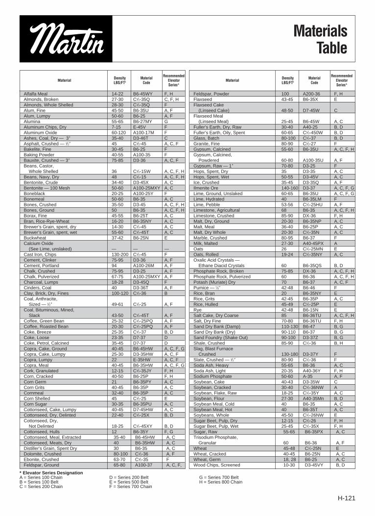
MaterialsTable
Alfalfa Meal 14-22 B6-45WY F, HAlmonds, Broken 27-30 C1⁄2-35Q C, F, HAlmonds, Whole Shelled 28-30 C1⁄2-35Q FAlum, Fine 45-50 B6-35U A, FAlum, Lumpy 50-60 B6-25 A, FAlumina 55-65 B6-27MY GAluminum Chips, Dry 7-15 E-45V FAluminum Oxide 60-120 A100-17M FAshes, Coal, Dry — 3″ 35-40 D3-46T CAsphalt, Crushed — 1⁄2″ 45 C1⁄2-45 A, C, FBakelite, Fine 30-45 B6-25 FBaking Powder 40-55 A100-35 FBauxite, Crushed — 3″ 75-85 D3-36 A, C, FBeans, Castor,
Whole Shelled 36 C1⁄2-15W A, C, F, HBeans, Navy, Dry 48 C1⁄2-15 A, C, F, HBentonite, Crude 34-40 D3-45X A, CBentonite — 100 Mesh 50-60 A100-25MXY A, CBoneblack 20-25 A100-25Y FBonemeal 50-60 B6-35 A, CBones, Crushed 35-50 D3-45 A, C, F, HBones, Ground 50 B6-35 A, C, F, HBorax, Fine 45-55 B6-25T A, CBran, Rice-Rye-Wheat 16-20 B6-35NY A, CBrewer’s Grain, spent, dry 14-30 C1⁄2-45 A, CBrewer’s Grain, spent, wet 55-60 C1⁄2-45T A, CBuckwheat 37-42 B6-25N ECalcium Oxide
(See Lime, unslaked) — — —Cast Iron, Chips 130-200 C1⁄2-45 FCement, Clinker 75-95 D3-36 A, FCement, Portland 94 A100-26M A, FChalk, Crushed 75-95 D3-25 A, FChalk, Pulverized 67-75 A100-25MXY A, FCharcoal, Lumps 18-28 D3-45Q FCinders, Coal 40 D3-36T A, FClay, Brick, Dry, Fines 100-120 C1⁄2-36 BCoal, Anthracite,
Sized — 1⁄2″ 49-61 C1⁄2-25 A, FCoal, Bituminous, Mined,
Slack 43-50 C1⁄2-45T A, FCoffee, Green Bean 25-32 C1⁄2-25PQ A, FCoffee, Roasted Bean 20-30 C1⁄2-25PQ A, FCoke, Breeze 25-35 C1⁄2-37 B, DCoke, Loose 23-35 D7-37 DCoke, Petrol, Calcined 35-45 D7-37 DCopra, Cake, Ground 40-45 B6-45HW A, C, F, GCopra, Cake, Lumpy 25-30 D3-35HW A, C, FCopra, Lumpy 22 E-35HW A, C, FCopra, Meal 40-45 B6-35HW A, C, F, GCork, Granulated 12-15 C1⁄2-35JY F, HCorn, Cracked 40-50 B6-25P F, HCorn Germ 21 B6-35PY A, CCorn Grits 40-45 B6-35P A, CCornmeal 32-40 B6-35P A, CCorn Shelled 45 C1⁄2-25 ECorn Sugar 30-35 B6-35PU A, CCottonseed, Cake, Lumpy 40-45 D7-45HW A, CCottonseed, Dry, Delinted 22-40 C1⁄2-25X B, DCottonseed, Dry,
Not Delinted 18-25 C1⁄2-45XY B, DCottonseed, Hulls 12 B6-35Y F, GCottonseed, Meal, Extracted 35-40 B6-45HW A, CCottonseed, Meats, Dry 40 B6-35HW A, CDistiller’s Grain, Spent Dry 30 B6-35 A, CDolomite, Crushed 80-100 C1⁄2-36 A, FEbonite, Crushed 63-70 C1⁄2-35 FFeldspar, Ground 65-80 A100-37 A, C, F,
Feldspar, Powder 100 A200-36 F, HFlaxseed 43-45 B6-35X EFlaxseed Cake
(Linseed Cake) 48-50 D7-45W CFlaxseed Meal
(Linseed Meal) 25-45 B6-45W A, CFuller’s Earth, Dry, Raw 30-40 A40-25 B, DFuller’s Earth, Oily, Spent 60-65 C1⁄2-450W B, DGlass, Batch 80-100 C1⁄2-37 B, DGranite, Fine 80-90 C1⁄2-27 FGypsum, Calcined 55-60 B6-35U A, C, F, HGypsum, Calcined,
Powdered 60-80 A100-35U A, FGypsum, Raw — 1″ 70-80 D3-25 FHops, Spent, Dry 35 D3-35 A, CHops, Spent, Wet 50-55 D3-45V A, CIce, Crushed 35-45 D3-35Q A, FIlmenite Ore 140-160 D3-37 A, C, F, GLime, Ground, Unslaked 60-65 B6-35U A, C, F, GLime, Hydrated 40 B6-35LM FLime, Pebble 53-56 C1⁄2-25HU A, FLimestone, Agricultural 68 B6-35 A, C, F, HLimestone, Crushed 85-90 DX-36 F, HMalt, Dry, Ground 20-30 B6-35NP A, CMalt, Meal 36-40 B6-25P A, CMalt, Dry Whole 20-30 C1⁄2-35N A, CMarble, Crushed 80-95 B6-37 FMilk, Malted 27-30 A40-45PX AOats 26 C1⁄2-25MN EOats, Rolled 19-24 C1⁄2-35NY A, COxalic Acid Crystals —
Ethane Diacid Crystals 60 B6-35QS B, DPhosphate Rock, Broken 75-85 DX-36 A, C, F, HPhosphate Rock, Pulverized 60 B6-36 A, C, F, HPotash (Muriate) Dry 70 B6-37 A, C, FPumice — 1⁄8″ 42-48 B6-46 FRice, Bran 20 B6-35NY ERice, Grits 42-45 B6-35P A, CRice, Hulled 45-49 C1⁄2-25P ERye 42-48 B6-15N ESalt Cake, Dry Coarse 85 B6-36TU A, C, F, HSalt, Dry Fine 70-80 B6-36TU F, HSand Dry Bank (Damp) 110-130 B6-47 B, GSand Dry Bank (Dry) 90-110 B6-37 B, GSand Foundry (Shake Out) 90-100 D3-37Z B, GShale, Crushed 85-90 C1⁄2-36 B, HSlag, Blast Furnace
Crushed 130-180 D3-37Y FSlate, Crushed — 1⁄2″ 80-90 C1⁄2-36 FSoda Ash, Heavy 55-65 B6-36 A, CSoda Ash, Light 20-35 A40-36Y F, HSodium Phosphate 50-60 A-35 A, FSoybean, Cake 40-43 D3-35W CSoybean, Cracked 30-40 C1⁄2-36NW ASoybean, Flake, Raw 18-25 C1⁄2-35Y A, CSoybean, Flour 27-30 A40-35Mn B, DSoybean Meal, Cold 40 B6-35 A, CSoybean Meal, Hot 40 B6-35T A, CSoybeans, Whole 45-50 C1⁄2-26NW ESugar Beet, Pulp, Dry 12-15 C1⁄2-26 F, HSugar Beet, Pulp, Wet 25-45 C1⁄2-35X F, HSugar, Raw 55-65 B6-35PX A, CTrisodium Phosphate,
Granular 60 B6-36 A, FWheat 45-48 C1⁄2-25N EWheat, Cracked 40-45 B6-25N A, CWheat, Germ 18, 28 B6-25 A, CWood Chips, Screened 10-30 D3-45VY B, D
Material DensityLBS/FT3
MaterialCode
RecommendedElevatorSeries*
Material DensityLBS/FT3
MaterialCode
RecommendedElevatorSeries*
*Elevator Series DesignationA = Series 100 Chain D = Series 200 Belt G = Series 700 BeltB = Series 100 Belt E = Series 500 Belt H = Series 800 ChainC = Series 200 Chain F = Series 700 Chain

H-122
CentrifugalDischarge Chain
C43-101 95 4 × 3 91⁄4 C-477 163 1⁄2 1 8 × 18 10 71⁄2 76 10 71⁄2 17⁄16 515 41 C43-101
C64-102 279 6 × 4 13 C-188 224 1⁄2 21⁄2 93⁄4 × 35 24 20 43 18 15 11⁄2 698 57 C64-102
C85-103 480 C-102B 203 113⁄4 × 35 14 18 43 10 13 11⁄2 794 73 C85-103
C85-104 545 C-102B 231 113⁄4 × 39 16 201⁄2 43 10 13 11⁄2 825 73 C85-104
C85-105 545 8 × 5 16 SS-102B 231 3⁄4 3 113⁄4 × 39 16 201⁄2 43 10 13 11⁄2 825 72 C85-105
C85-107 615 C-102B 260 113⁄4 × 42 19 241⁄4 41 14 18 2 930 80 C85-107
C85-108 615 SS-102B 260 113⁄4 × 42 19 241⁄4 41 14 18 2 900 83 C85-108
C106-110 935 16 C-102B 231 133⁄4 × 42 16 201⁄2 43 12 151⁄2 910 89 C106-110
C106-111 935 16 SS-102B 231 133⁄4 × 42 16 201⁄2 43 12 151⁄2 980 90 C106-111
C106-112 965 10 × 6 18 C-110 268 1 31⁄2 133⁄4 × 48 13 25 41 11 211⁄4 2 1055 90 C106-112
C106-113 965 18 SS-110 268 133⁄4 × 48 13 25 41 11 211⁄4 1160 93 C106-113
C106-116 1053 16 C-102B 260 133⁄4 × 48 19 241⁄4 41 16 201⁄2 1175 94 C106-116
C127-117 1530 18 SS-110 268 153⁄4 × 48 13 25 41 9 171⁄2 2 1155 97 C127-117
C127-119 1667 12 × 7
16 C-102B 260 11⁄4 4
153⁄4 × 48 19 241⁄4 41 14 18 2 1090 102 C127-119
C127-120 1745 18 SS-110 306 153⁄4 × 54 16 303⁄4 38 12 231⁄4 27⁄16 1480 107 C-127-120
C127-122 1945 16 C-102B 303 153⁄4 × 54 24 301⁄2 38 19 241⁄4 27⁄16 1385 104 C127-122
C147-123 1699 19 C-111 260 173⁄4 × 48 16 241⁄2 41 12 181⁄4 1390 107 C147-123
C147-124 1850 18 SS-110 268 173⁄4 × 48 13 25 41 9 171⁄2 1367 102 C147-124
C147-126 2018 14 × 7 16 C-102B 260 11⁄4 4 173⁄4 × 48 19 241⁄4 41 14 18 27⁄16 1255 103 C147-126
C147-127 1980 19 C-111 303 173⁄4 × 54 20 301⁄2 38 16 241⁄4 1600 110 C147-127
C147-128 2092 18 SS-110 306 173⁄4 × 54 16 303⁄4 38 12 231⁄4 1560 107 C147-128
C147-130 2352 16 C-102B 303 173⁄4 × 54 24 301⁄2 38 19 241⁄4 1405 108 C147-130
C168-131 2512 19 C-111 260 193⁄4 × 48 16 241⁄2 41 11 17 1454 116 C168-131
C168-132 2520 16 × 8 18 SS-110 247 11⁄2 41⁄2 193⁄4 × 48 12 23 41 9 171⁄2 27⁄16 1489 122 C168-132
C168-133 2928 19 C-111 303 193⁄4 × 54 20 301⁄2 38 14 211⁄4 1658 124 C168-133
C168-134 3122 18 SS-110 306 193⁄4 × 54 16 303⁄4 38 11 211⁄4 1783 119 C168-134
Capacity
ElevatorNumber
Capacityin CubicFeet perHour �
ChainNominal1
CasingSize
Head Sprocket Boot Sprocket Approx. Wt. (Lbs.)Speed
inF.P.M. 100%
Number ofTeeth
Pitch1
Diameter RPM Number ofTeeth
Pitch1
DiameterShaft1
Diameter
TerminalsIncludingMachinery
Inter-mediate*
per Ft.
ElevatorNumber
10%
Buckets1
Size Spacing
Max1
Lump Size
� Based on 75% full bucket* Includes casing, chain and buckets1 Dimensions are in inches
Series 100 Chain (Series 200 is for Head Take-up)Centrifugal discharge chain type elevators handle a variety of relatively free-flowing dry materials with smallto medium lump sizes that are mildly to moderately abrasive.
BucketsCapacities and horsepower listed are for style AA buckets. Style A, AA-RB and Salem can be furnished.Style C may also be used to handle wet or sticky materials. Consult the factory for a specific recommenda-tion.
ChainCentrifugal discharge chain type elevators are furnished with either combination chain for light to mediumservice or all steel (steel knuckle) chain for medium to severe service or when a higher chain working load isrequired.

H-123
Centrifugal Discharge ChainSeries 100
C43-101 0-100 17⁄16 1 0-100 17⁄16 1 0-100 17⁄16 1 0-80 17⁄16 1 C43-101
81-100 17⁄16 11⁄2
C64-102 0-61 115⁄16 1 0-59 115⁄16 1 0-57 115⁄16 1 0-54 115⁄16 11⁄2 C64-102
62-100 27⁄16 1 60-83 27⁄16 11⁄2 57-85 27⁄16 11⁄2 55-75 27⁄16 2
84-100 27⁄16 2 86-100 215⁄16 2 76-90 215⁄16 3
91-100 215⁄16 3
C85-103 0-35 1-15⁄16 1 0-34 115⁄16 1 0-29 115⁄16 11⁄2 0-27 115⁄16 11⁄2 C85-103
C85-104 36-71 27⁄16 11⁄2 35-60 27⁄16 11⁄2 30-54 27⁄16 2 28-40 27⁄16 2 C85-104
C85-105 72-100 215⁄16 2 61-80 215⁄16 2 55-81 27⁄16 3 41-60 27⁄16 3 C85-105
C85-107 81-100 215⁄16 3 82-100 215⁄16 5 61-100 215⁄16 5 C85-107
C85-108 C85-108
C106-110 0-28 115⁄16 1 0-27 115⁄16 11⁄2 0-21 115⁄16 11⁄2 0-25 27⁄16 2 C106-110
C106-111 29-53 27⁄16 11⁄2 28-50 27⁄16 2 22-33 27⁄16 2 26-34 27⁄16 3 C106-111
C106-112 54-71 215⁄16 2 51-75 215⁄16 3 34-50 27⁄16 3 35-62 215⁄16 5 C106-112
C106-113 72-100 37⁄16 3 76-100 37⁄16 5 51-83 215⁄16 5 63-93 37⁄16 71⁄2 C106-113
84-100 37⁄16 71⁄2 94-100 37⁄16 10
C106-116 C106-116
C127-117 0-20 115⁄16 11⁄2 0-27 27⁄16 3 0-23 27⁄16 3 0-23 27⁄16 5 C127-117
C127-119 21-33 27⁄16 2 28-48 215⁄16 5 24-39 215⁄16 5 24-34 215⁄16 71⁄2 C127-119
C127-120 34-40 27⁄16 3 49-58 37⁄16 5 40-58 215⁄16 71⁄2 35-58 37⁄16 10 C127-120
41-69 215⁄16 5 59-87 37⁄16 71⁄2 59-78 37⁄16 10 59-100 315⁄16 20
C127-122 70-100 37⁄16 71⁄2 88-100 315⁄16 10 79-100 315⁄16 15 C127-122
C147-123 0-34 27⁄16 3 0-23 27⁄16 5 0-21 27⁄16 5 0-34 215⁄16 71⁄2 C147-123
C147-124 35-58 215⁄16 5 24-41 215⁄16 5 22-37 215⁄16 71⁄2 35-47 37⁄16 10 C147-124
C147-126 59-68 215⁄16 5 42-71 37⁄16 71⁄2 38-63 37⁄16 10 48-71 315⁄16 15 C147-126
C147-127 69-95 37⁄16 71⁄2 72-95 315⁄16 10 64-94 315⁄16 15 71-91 315⁄16 20 C147-127
C147-128 96-100 315⁄16 71⁄2 96-100 315⁄16 15 95-100 315⁄16 20 92-100 315⁄16 25 C147-128
C147-130 C147-130
C168-131 0-44 215⁄16 5 0-37 215⁄16 5 0-27 215⁄16 71⁄2 0-37 37⁄16 10 C168-131
C168-132 45-73 37⁄16 71⁄2 38-55 37⁄16 71⁄2 28-36 37⁄16 71⁄2 38-55 315⁄16 15 C168-132
C168-133 74-100 315⁄16 10 56-74 315⁄16 10 37-48 37⁄16 10 56-66 315⁄16 20 C168-133
75-87 315⁄16 15 49-73 315⁄16 15 67-74 47⁄16 20
C168-134 88-100 47⁄16 20 74-100 47⁄16 20 75-100 47⁄16 25 C168-134
Centrifugal Discharge ChainSeries 100
Horsepower*
Material Density (Pounds per Cubic Feet)
ElevatorNumber
ElevatorNumber
35 50 75 100
CentersHead
FeetShaft
DiameterHP Centers
Head
FeetShaft
DiameterHP Centers
Head
FeetShaft
DiameterHP Centers
Head
FeetShaft
DiameterHP
*Based on 100% full bucket *For nominal dimensions see page H-131.
HP
35 50 75 100
HP
and
and
and
and
and
and
and
and
and
and

H-124
CentrifugalDischarge Belt
Series 100 Belt (Series 200 is for Head Take-up)Centrifugal discharge belt type elevators handle a variety of relatively free-flowing dry materials with small tomedium lump sizes that are mildly, moderately or extremely abrasive.
BucketsCapacities and horsepower listed are for style AA buckets. Style A, AA-RB and Salem can be furnished. Style Cmay also be used to handle wet or sticky materials. Consult the factory for a specific recommendation.
BeltCentrifugal discharge belt type elevators are furnished with 100% polyester carcass PVC belting specificallydesigned for elevator service. Many other types of belts and covers are available.
B43-139 107 4 × 3 8 5 159 1⁄4 1 8 × 18 8 76 8 17⁄16 785 42 B43-139
B64-140 336 6 × 4 13 7 270 1⁄2 21⁄2 113⁄4 × 39 24 43 16 11⁄2 922 51 B64-140
B64-141 294 6 × 4 13 7 236 113⁄4 × 35 20 45 16 11⁄2 892 51 B64-141
B85-142 558 8 × 5 16 9 236 3⁄4 3 133⁄4 × 39 20 45 14 2 889 66 B85-142
B85-143 638 8 × 5 16 9 270 133⁄4 × 42 24 43 16 2 1120 78 B85-143
B106-144 956 10 × 6 16 11 236 1 31⁄2 153⁄4 × 42 20 45 16 2 1130 76 B106-144
B106-145 1094 10 × 6 16 11 270 153⁄4 × 48 24 43 20 2 1292 82 B106-145
B127-146S 4938 12 × 7 16 24 385 11⁄4 4 28 × 64S 42 35 30 27⁄16 2345 141 B127-146S
B127-146 1540 12 × 7 18 13 270 11⁄4 4 173⁄4 × 48 24 43 20 27⁄16 1419 85 B127-146
B127-147 1791 12 × 7 18 13 314 173⁄4 × 54 30 40 24 27⁄16 1692 92 B127-147
B147-148 1864 14 × 7 18 15 270 11⁄4 4 193⁄4 × 48 24 43 20 27⁄16 1542 93 B147-148
B147-149 2168 14 × 7 18 15 314 193⁄4 × 54 30 45 24 27⁄16 1803 99 B147-149
B168-150 2409 16 × 8 18 18 236 11⁄2 41⁄2 223⁄4 × 48 20 45 18 27⁄16 1963 95 B168-150
B168-152 3204 16 × 8 18 18 314 223⁄4 × 54 30 40 24 27⁄16 2075 109 B168-152
Capacity
ElevatorNumber
Capacity inCubic Feetper Hour �
Belt1
Width
Nominal1
CasingSize
Head Boot Approx. Wt. (Lbs.)Speed inF.P.M.
100%Pulley
Diameter1
ShaftRPM
PulleyDiameter1
ShaftDiameter
TerminalsIncludingMachinery
Inter-mediate*
per Ft.
ElevatorNumber
10%
Buckets1
Size Spacing
Max1
Lump Size
� Based on 75% full bucket* Includes casing, belt and buckets1 Dimensions are in inches
Staggered Staggered

H-125
B43-139 0-100 17⁄16 1 0-100 17⁄16 1 0-100 17⁄16 1 0-80 17⁄16 1 B43-139
81-100 115⁄16 11⁄2
B64-140 0-80 115⁄16 1 0-66 115⁄16 1 0-44 115⁄16 1 0-33 115⁄16 1 B64-140
81-100 115⁄16 11⁄2 67-80 115⁄16 11⁄2 45-66 115⁄16 11⁄2 34-50 115⁄16 11⁄2
B64-141 81-100 115⁄16 2 67-88 115⁄16 2 51-66 115⁄16 2 B64-141
89-100 27⁄16 3 67-92 115⁄16 3
93-100 27⁄16 5
B85-142 0-42 115⁄16 1 0-33 115⁄16 1 0-33 115⁄16 11⁄2 0-25 115⁄16 11⁄2 B85-142
43-71 27⁄16 11⁄2 34-50 27⁄16 11⁄2 34-44 27⁄16 2 26-33 27⁄16 2
B85-143 72-95 215⁄16 2 51-66 27⁄16 2 45-66 27⁄16 3 34-50 27⁄16 3 B85-143
96-100 215⁄16 3 67-90 215⁄16 3 67-100 215⁄16 5 51-83 215⁄16 5
91-100 215⁄16 5 84-100 215⁄16 71⁄2
B106-144 0-25 115⁄16 1 0-24 115⁄16 11⁄2 0-20 115⁄16 11⁄2 0-30 27⁄16 3 B106-144
26-42 27⁄16 11⁄2 25-40 27⁄16 2 21-26 27⁄16 2 31-50 215⁄16 5
B106-145 43-57 215⁄16 2 41-60 215⁄16 3 27-40 27⁄16 3 51-75 37⁄16 71⁄2 B106-145
58-85 215⁄16 3 61-100 37⁄16 5 41-66 215⁄16 5 76-100 37⁄16 10
86-100 37⁄16 5 67-100 37⁄16 71⁄2
B127-146S 0-27 215⁄16 5 0-34 37⁄16 71⁄2 0-30 37⁄16 10 0-35 315⁄16 15 B127-146S
28-44 37⁄16 71⁄2 35-46 315⁄16 10 31-46 315⁄16 15 36-46 47⁄16 20
45-66 315⁄16 10 47-69 47⁄16 15 47-61 47⁄16 20 47-58 415⁄16 25
67-89 47⁄16 15 70-93 415⁄16 20 62-77 415⁄16 25 59-69 415⁄16 30
90-100 415⁄16 15 94-100 415⁄16 25 78-92 415⁄16 30 70-93 57⁄16 40
B127-146 0-35 27⁄16 2 0-34 27⁄16 3 0-25 27⁄16 3 0-31 215⁄16 5 B127-146
36-53 215⁄16 3 35-59 215⁄16 5 26-41 215⁄16 5 32-46 37⁄16 71⁄2
B127-147 54-89 37⁄16 5 60-93 37⁄16 71⁄2 42-62 37⁄16 71⁄2 47-62 37⁄16 10 B127-147
90-100 37⁄16 71⁄2 94-100 315⁄16 10 63-72 37⁄16 10 63-93 315⁄16 15
73-100 315⁄16 15 94-100 47⁄16 20
B147-148 0-27 27⁄16 3 0-20 27⁄16 5 0-17 27⁄16 5 0-15 27⁄16 5 B147-148
B147-149 28-45 215⁄16 3 21-39 215⁄16 71⁄2 18-34 215⁄16 5 16-33 215⁄16 71⁄2 B147-149
46-75 37⁄16 5 40-76 37⁄16 71⁄2 35-52 37⁄16 71⁄2 34-51 37⁄16 10
76-100 315⁄16 71⁄2 77-100 315⁄16 10 53-69 315⁄16 10 52-76 315⁄16 15
76-100 47⁄16 15 77-100 47⁄16 20
B168-150 0-28 215⁄16 5 0-28 215⁄16 5 0-35 37⁄16 71⁄2 0-29 37⁄16 10 B168-150
B168-152 29-51 37⁄16 5 29-46 37⁄16 71⁄2 36-47 315⁄16 10 44 315⁄16 15 B168-152
52-76 315⁄16 71⁄2 47-70 315⁄16 10 48-71 47⁄16 15 65 47⁄16 20
77-100 47⁄16 10 71-92 47⁄16 15 72-95 415⁄16 20 89 415⁄16 25
92-100 415⁄16 20 96-100 415⁄16 25 100 57⁄16 30
Centrifugal Discharge BeltSeries 100
Horsepower*
Material Density (Pounds per Cubic Feet)
ElevatorNumber
ElevatorNumber
35 50 75 100
CentersHead
FeetShaft
DiameterHP Centers
Head
FeetShaft
DiameterHP Centers
Head
FeetShaft
DiameterHP Centers
Head
FeetShaft
DiameterHP
*Based on 100% full bucket *For nominal dimensions see page H-131.
35 50 75 100
HPHP HP HP
and and
and and
and and
Staggered Staggered
and and

H-126
C85-766 590 8 × 5 × 73⁄4 8 C-102B 125 3⁄4 21⁄2 113⁄4 × 39 16 201⁄2 23 11 141⁄4 11⁄2 902 82 C85-766
C85-767 590 8 × 5 × 73⁄4 8 SS-102B 125 3⁄4 21⁄2 113⁄4 × 39 16 201⁄2 23 11 141⁄4 11⁄2 899 83 C85-767
C105-768 750 10 × 5 × 73⁄4 8 C-102B 125 3⁄4 21⁄2 133⁄4 × 39 16 201⁄2 23 11 141⁄4 2 889 93 C105-768
C105-769 750 10 × 5 × 73⁄4 8 SS-102B 125 3⁄4 21⁄2 133⁄4 × 39 16 201⁄2 23 11 141⁄4 2 842 94 C105-769
C107-770 1080 10 × 7 × 115⁄8 12 C-110 125 1 3 133⁄4 × 48 13 25 19 10 191⁄2 2 1167 100 C107-770
C107-771 1080 10 × 7 × 115⁄8 12 SS-110 125 1 3 133⁄4 × 48 13 25 19 10 191⁄2 2 1271 103 C107-771
C127-772 1294 12 × 7 × 115⁄8 12 C-110 125 1 3 153⁄4 × 48 13 25 19 10 191⁄2 27⁄16 1230 113 C127-772
C127-773 1294 12 × 7 × 115⁄8 12 SS-110 125 1 3 153⁄4 × 48 13 25 19 10 191⁄2 27⁄16 1325 115 C127-773
C147-774 1519 14 × 7 × 115⁄8 12 C-110 125 1 3 173⁄4 × 48 13 25 19 10 191⁄2 27⁄16 1301 117 C147-774
C147-775 1519 14 × 7 × 115⁄8 12 SS-110 125 1 3 173⁄4 × 48 13 25 19 10 191⁄2 27⁄16 1399 121 C147-775
C128-776 1550 12 × 8 × 115⁄8 12 C-110 125 11⁄4 4 153⁄4 × 48 13 25 19 9 171⁄2 27⁄16 1295 116 C128-776
C128-777 1550 12 × 8 × 115⁄8 12 SS-110 125 11⁄4 4 153⁄4 × 48 13 25 19 9 171⁄2 27⁄16 1515 122 C128-777
C148-778 1817 14 × 8 × 115⁄8 12 C-110 125 11⁄4 4 173⁄4 × 48 13 25 19 9 171⁄2 27⁄16 1453 119 C148-778
C148-779 1817 14 × 8 × 115⁄8 12 SS-110 125 11⁄4 4 173⁄4 × 48 13 25 19 9 171⁄2 27⁄16 1600 126 C148-779
C168-781 2090 16 × 8 × 115⁄8 12 SS-110 125 11⁄2 41⁄2 193⁄4 × 48 13 25 19 9 171⁄2 27⁄16 1667 133 C168-781
C188-783 2340 18 × 8 × 115⁄8 12 SS-110 125 11⁄2 41⁄2 223⁄4 × 48 13 25 19 9 171⁄2 27⁄16 1701 140 C188-783
ChainNominal1
CasingSize
Head Sprocket Boot Sprocket Approximate Wt. (Lbs.)Speed
inF.P.M.
No. ofTeeth
PitchDia1
No. ofTeeth
PitchDia1
ShaftDia1
TerminalsIncludingMachinery
Buckets1
Size Spacing
Max1
Lump Size
ContinuousDischarge Chain
� Based on 75% full bucket* Includes casing, chain and buckets1 Dimensions are in inches
Series 700 Chain (Series 800 is for Head Take-up)Continuous discharge chain type elevators will handle various free-flowing dry or sluggish materialswhich contain medium to large lumps and are mildly, moderately or extremely abrasive.
BucketsCapacities and horsepower listed are for a 10 gauge medium-front, non-overlapping style fabricatedsteel bucket. High front style buckets are available. Consult the factory for a specific recommendation.
ChainContinuous discharge chain type elevators are furnished with combination chain for mild to moderateservice or all steel (steel knuckle) chain for moderate to severe service or when a higher chain work-ing load is required.
Capacity
ElevatorNumber
Capacityin CubicFeet perHour� 100% RPM
Inter-mediate*
per Ft.
ElevatorNumber
10%

H-127
C85-776 0-16 115⁄16 1 0-15 115⁄16 1 0-14 115⁄16 1 0-16 27⁄16 11⁄2 B85-776
C85-767 17-35 27⁄16 1 16-33 27⁄16 1 15-31 27⁄16 11⁄2 17-29 215⁄16 2 B85-767
36-61 215⁄16 11⁄2 34-58 215⁄16 11⁄2 32-53 215⁄16 2 30-60 315⁄16 3
62-100 37⁄16 2 59-80 37⁄16 2 54-71 37⁄16 3 61-100 47⁄16 5
81-100 37⁄16 3 72-100 315⁄16 5
C105-768 0-13 115⁄16 1 0-27 27⁄16 1 0-25 27⁄16 11⁄2 0-21 27⁄16 11⁄2 C105-768
C105-769 14-28 27⁄16 1 28-42 215⁄16 11⁄2 26-38 215⁄16 2 22-28 215⁄16 2 C105-769
29-50 215⁄16 11⁄2 43-57 37⁄16 2 39-57 37⁄16 3 29-42 37⁄16 3
51-81 37⁄16 2 58-81 37⁄16 3 58-90 315⁄16 5 43-71 315⁄16 5
82-100 315⁄16 3 82-100 315⁄16 5 91-100 315⁄16 71⁄2 72-100 47⁄16 71⁄2
C107-770 0-24 27⁄16 11⁄2 0-22 27⁄16 11⁄2 0-20 27⁄16 11⁄2 0-16 27⁄16 2 C107-770
C107-771 25-42 215⁄16 2 23-40 215⁄16 2 21-29 215⁄16 2 17-30 215⁄16 3 C107-771
43-69 37⁄16 3 41-65 37⁄16 3 30-44 37⁄16 3 31-55 315⁄16 5
70-100 315⁄16 5 66-100 315⁄16 5 45-74 315⁄16 5 56-83 47⁄16 71⁄2
75-100 47⁄16 71⁄2 84-100 47⁄16 10
C127-772 0-21 27⁄16 1 0-22 27⁄16 11⁄2 0-16 27⁄16 2 0-25 215⁄16 3 C127-772
C127-773 22-38 215⁄16 11⁄2 23-36 215⁄16 2 17-30 215⁄16 3 26-38 37⁄16 5 C127-773
39-51 37⁄16 2 37-54 37⁄16 3 31-60 315⁄16 5 39-64 315⁄16 71⁄2
52-77 315⁄16 3 55-90 315⁄16 5 61-90 47⁄16 71⁄2 65-90 47⁄16 10
78-100 47⁄16 5 91-100 47⁄16 71⁄2 91-100 47⁄16 10 91-100 415⁄16 15
C147-774 0-20 27⁄16 1 0-25 215⁄16 11⁄2 0-22 215⁄16 2 0-23 215⁄16 3 C147-774
C147-775 21-35 215⁄16 11⁄2 26-33 215⁄16 2 23-33 37⁄16 3 24-35 37⁄16 5 C147-775
36-47 37⁄16 2 34-50 37⁄16 3 34-55 315⁄16 5 36-59 315⁄16 71⁄2
48-71 315⁄16 3 51-76 315⁄16 5 56-83 47⁄16 71⁄2 60-83 47⁄16 10
72-100 47⁄16 5 77-100 47⁄16 71⁄2 84-100 415⁄16 10 84-100 415⁄16 15
C128-776 0-19 27⁄16 1 0-18 27⁄16 11⁄2 0-20 215⁄16 2 0-22 215⁄16 3 C128-776
C128-777 20-32 215⁄16 11⁄2 19-30 215⁄16 2 21-30 37⁄16 3 23-34 37⁄16 5 C128-777
33-43 37⁄16 2 31-46 37⁄16 3 31-51 315⁄16 5 35-57 315⁄16 71⁄2
44-65 315⁄16 3 47-73 315⁄16 5 52-76 47⁄16 71⁄2 58-76 47⁄16 10
66-100 47⁄16 5 74-100 47⁄16 71⁄2 77-100 415⁄16 10 77-100 415⁄16 15
C148-778 0-17 27⁄16 11⁄2 0-23 215⁄16 2 0-21 215⁄16 3 0-28 37⁄16 5 C148-778
C148-779 18-30 215⁄16 2 24-35 37⁄16 3 22-31 37⁄16 5 29-44 315⁄16 71⁄2 C148-779
31-49 37⁄16 3 36-58 315⁄16 5 32-53 315⁄16 71⁄2 45-58 47⁄16 10
50-68 315⁄16 5 59-88 47⁄16 71⁄2 54-75 47⁄16 10 59-88 415⁄16 15
69-100 47⁄16 71⁄2 89-100 415⁄16 10 76-100 415⁄16 15 89-100 57⁄16 20
C168-781 0-26 215⁄16 2 0-22 215⁄16 2 0-18 215⁄16 3 0-25 37⁄16 5 C168-781
27-44 37⁄16 3 23-33 37⁄16 3 19-28 37⁄16 5 26-41 315⁄16 71⁄2
45-61 315⁄16 5 34-55 315⁄16 5 29-46 315⁄16 71⁄2 42-55 47⁄16 10
62-79 47⁄16 5 56-79 47⁄16 71⁄2 47-67 47⁄16 10 56-83 415⁄16 15
80-100 415⁄16 71⁄2 80-100 415⁄16 10 68-100 415⁄16 15 84-100 57⁄16 20
C188-783 0-22 215⁄16 2 0-28 37⁄16 3 0-23 37⁄16 5 0-20 37⁄16 5 C188-783
23-37 37⁄16 3 29-47 315⁄16 5 24-38 315⁄16 71⁄2 21-34 315⁄16 71⁄2
38-51 315⁄16 5 48-66 47⁄16 71⁄2 39-55 47⁄16 10 35-47 47⁄16 10
52-68 47⁄16 5 67-95 415⁄16 10 56-77 415⁄16 15 48-69 415⁄16 15
69-100 415⁄16 71⁄2 96-100 57⁄16 15 78-100 57⁄16 20 70-93 57⁄16 20
Continuous Discharge ChainSeries 700
Horsepower*Material Density (Pounds per Cubic Feet)
ElevatorNumber
ElevatorNumber
CentersHead
FeetShaft
Diameter
CentersHead
FeetShaft
Diameter
CentersHead
FeetShaft
Diameter
CentersHead
FeetShaft
Diameter
*Based on 100% full bucket *For nominal dimensions see page H-131.
35 50 75 100
HP HP HP HP

H-128
B85-790 945 8 × 5 × 73⁄4 8 9 200 3⁄4 21⁄2 113⁄4 × 39 20 38.2 14 11⁄2 650 75 B85-790
B105-791 1215 10 × 5 × 73⁄4 8 11 200 3⁄4 21⁄2 133⁄4 × 39 20 38.2 14 11⁄2 660 81 B105-791
B107-792 1620 10 × 7 × 115⁄8 12 11 200 1 3 133⁄4 × 48 24 31.8 20 2 915 93 B107-792
B127-793 1962 12 × 7 × 115⁄8 12 13 200 1 3 153⁄4 × 48 24 31.8 20 2 1067 105 B127-793
B147-794 2277 14 × 7 × 115⁄8 12 15 200 1 3 173⁄4 × 48 24 31.8 20 2 1246 117 B147-794
B128-795 2475 12 × 8 × 115⁄8 12 13 200 11⁄4 4 153⁄4 × 48 24 31.8 20 2 1181 110 B128-795
B148-796 2925 14 × 8 × 115⁄8 12 15 200 11⁄4 4 173⁄4 × 48 24 31.8 20 27⁄16 1297 117 B148-796
B168-797 3375 16 × 8 × 115⁄8 12 17 200 11⁄2 41⁄2 193⁄4 × 48 24 31.8 20 27⁄16 1426 124 B168-797
B188-798 3780 18 × 8 × 115⁄8 12 19 200 11⁄2 41⁄2 223⁄4 × 48 20 38.2 18 27⁄16 1819 140 B188-798
Capacity
ElevatorNumber
Capacityin CubicFeet perHour �
BeltWidth1
Nominal1
CasingSize
Head Boot Approx. Weight (Lbs.)Speed
inF.P.M. 100%
PulleyDia.1
ShaftRPM
PulleyDia.1
ShaftDia.1
TerminalsIncludingMachinery
Inter-mediate*
per Ft.
ElevatorNumber
10%
Buckets1
Size Spacing
MaxLump Size
� Based on 75% full bucket* Includes casing, belt and buckets1 Dimensions are in inches
ContinuousDischarge Belt
Series 700 Belt (Series 800 is for Head Take-up)Continuous discharge belt type elevators will handle various free-flowing dry or sluggish materialswhich contain medium to large lumps and are mildly, moderately or extremely abrasive.
BucketsCapacities and horsepower listed are for a 10 gauge medium front, non-overlapping style fabricatedsteel bucket. High front style buckets are available. Consult the factory for a specific recommenda-tion.
BeltContinuous discharge belt type elevators are furnished with 100% polyester carcass PVC beltingspecifically designed for elevator service. Many other types of belt and covers are available.
H-129
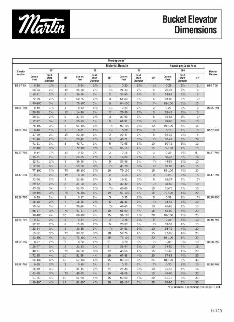
Bucket ElevatorDimensions
B85-790 0-25 115⁄16 1 0-24 115⁄16 1 0-20 115⁄16 11⁄2 0-25 27⁄16 2 B85-790
26-54 27⁄16 11⁄2 25-38 27⁄16 11⁄2 21-33 27⁄16 2 26-37 27⁄16 3
55-71 215⁄16 2 39-49 27⁄16 2 34-50 215⁄16 3 38-62 215⁄16 5
72-89 215⁄16 3 50-75 215⁄16 3 51-83 37⁄16 5 63-80 37⁄16 71⁄2
90-100 37⁄16 3 76-100 37⁄16 5 84-100 315⁄16 71⁄2 81-100 315⁄16 10
B105-791 0-19 115⁄16 1 0-13 115⁄16 11⁄2 0-24 27⁄16 2 0-27 27⁄16 3 B105-791
20-38 27⁄16 11⁄2 14-36 27⁄16 2 25-36 215⁄16 3 28-45 215⁄16 5
39-51 215⁄16 2 37-54 215⁄16 3 37-60 37⁄16 5 46-68 37⁄16 71⁄2
52-77 37⁄16 3 55-90 37⁄16 5 61-91 315⁄16 71⁄2 69-90 315⁄16 10
78-100 37⁄16 5 91-100 315⁄16 71⁄2 92-100 315⁄16 10 91-100 47⁄16 15
B107-792 0-16 115⁄16 1 0-21 115⁄16 11⁄2 0-28 215⁄16 3 0-18 27⁄16 3 B107-792
17-30 27⁄16 11⁄2 22-28 27⁄16 2 29-47 37⁄16 5 19-35 215⁄16 5
31-40 215⁄16 2 29-42 215⁄16 3 48-71 315⁄16 71⁄2 36-49 37⁄16 71⁄2
41-61 37⁄16 3 43-71 37⁄16 5 72-95 315⁄16 10 50-71 315⁄16 10
62-100 315⁄16 5 72-100 315⁄16 71⁄2 96-100 47⁄16 15 72-100 47⁄16 15
B127-793 0-14 115⁄16 11⁄2 0-23 27⁄16 2 0-18 27⁄16 3 0-29 215⁄16 5 B127-793
15-31 27⁄16 2 24-35 215⁄16 3 19-36 215⁄16 5 30-43 37⁄16 71⁄2
32-51 215⁄16 3 36-58 37⁄16 5 37-48 37⁄16 71⁄2 44-58 315⁄16 10
52-76 37⁄16 5 59-88 315⁄16 71⁄2 49-78 315⁄16 10 59-88 47⁄16 15
77-100 315⁄16 71⁄2 89-100 315⁄16 10 79-100 47⁄16 15 89-100 415⁄16 20
B147-794 0-21 27⁄16 11⁄2 0-20 27⁄16 2 0-15 27⁄16 3 0-25 215⁄16 5 B147-794
22-28 215⁄16 2 21-30 215⁄16 3 16-31 215⁄16 5 26-37 37⁄16 71⁄2
29-42 215⁄16 3 31-50 37⁄16 5 32-42 37⁄16 71⁄2 38-50 315⁄16 10
43-68 37⁄16 5 51-75 315⁄16 71⁄2 43-66 315⁄16 10 51-75 47⁄16 15
69-100 315⁄16 71⁄2 76-100 47⁄16 10 67-100 47⁄16 15 76-100 415⁄16 20
B128-795 0-25 27⁄16 2 0-17 27⁄16 3 0-30 215⁄16 5 0-33 37⁄16 71⁄2 B128-795
26-38 215⁄16 3 18-35 215⁄16 5 31-41 37⁄16 71⁄2 34-45 315⁄16 10
39-64 37⁄16 5 36-46 37⁄16 71⁄2 42-60 315⁄16 10 46-68 47⁄16 15
65-97 315⁄16 71⁄2 47-87 315⁄16 10 61-90 47⁄16 15 69-90 415⁄16 20
98-100 47⁄16 10 88-100 47⁄16 15 91-100 415⁄16 20 91-100 415⁄16 25
B148-796 0-21 27⁄16 2 0-14 27⁄16 3 0-25 215⁄16 5 0-38 315⁄16 10 B148-796
22-32 215⁄16 3 15-29 215⁄16 5 26-33 37⁄16 71⁄2 39-57 47⁄16 15
33-54 37⁄16 5 30-38 37⁄16 71⁄2 34-51 315⁄16 10 58-76 415⁄16 20
55-82 315⁄16 71⁄2 39-72 315⁄16 10 52-76 47⁄16 15 77-92 415⁄16 25
83-100 47⁄16 10 73-100 47⁄16 15 77-100 415⁄16 20 93-100 57⁄16 30
B168-797 0-27 215⁄16 3 0-20 215⁄16 3 0-28 37⁄16 71⁄2 0-33 315⁄16 10 B168-797
28-47 37⁄16 5 21-33 37⁄16 5 29-44 315⁄16 10 34-50 47⁄16 15
48-71 315⁄16 71⁄2 34-50 315⁄16 71⁄2 45-66 47⁄16 15 51-66 415⁄16 20
72-95 47⁄16 10 51-66 47⁄16 10 67-88 415⁄16 20 67-83 415⁄16 25
96-100 415⁄16 15 67-100 415⁄16 15 89-100 57⁄16 25 84-100 57⁄16 30
B188-798 0-25 215⁄16 3 0-30 37⁄16 5 0-23 37⁄16 71⁄2 0-30 315⁄16 10 B188-798
26-40 37⁄16 5 31-45 315⁄16 71⁄2 24-40 315⁄16 10 31-45 47⁄16 15
41-60 315⁄16 71⁄2 46-60 47⁄16 10 41-59 47⁄16 15 46-60 415⁄16 20
61-85 47⁄16 10 61-90 415⁄16 15 60-80 415⁄16 20 61-75 57⁄16 25
86-100 415⁄16 15 91-100 415⁄16 20 81-100 57⁄16 25 76-90 57⁄16 30
Horsepower*
Material Density Pounds per Cubic Feet
ElevatorNumber
ElevatorNumber
35 50 75 100
CentersHead
FeetShaft
DiameterHP Centers
Head
FeetShaft
DiameterHP Centers
Head
FeetShaft
DiameterHP Centers
Head
FeetShaft
DiameterHP
*For nominal dimensions see page H-131.
H-130
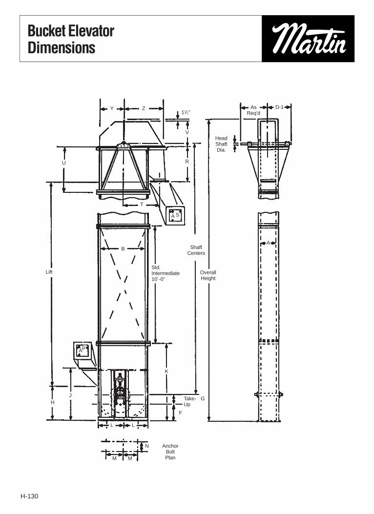
Bucket ElevatorDimensions
LiftStd.Intermediate10´-0″
OverallHeight
ShaftCenters
AnchorBoltPlan
Take-Up
HeadShaftDia.
Y
U
H
K
JG
F
L
N
MM
L
T
SA
PA
Z D-1AsReq’d11⁄2″
V
R
AB

H-131
Index/Bucket ElevatorDimensions
8 18 9 6 271⁄4 363⁄4 42 9 6 10 6 15 8 171⁄2 36 14 9 201⁄4 13
93⁄4 35 13 9 261⁄2 43 72 171⁄2 141⁄2 131⁄2 13 293⁄4 10 281⁄2 42 191⁄2 171⁄2 301⁄2 13
113⁄4 39 14 9 261⁄2 43 72 191⁄2 161⁄2 151⁄2 13 311⁄2 10 301⁄2 42 211⁄2 191⁄2 321⁄2 14
113⁄4 35 13 9 261⁄2 43 72 171⁄2 141⁄2 151⁄2 13 293⁄4 10 281⁄2 42 191⁄2 171⁄2 301⁄2 14
113⁄4 39 14 9 261⁄2 43 72 191⁄2 161⁄2 151⁄2 13 311⁄2 10 301⁄2 42 211⁄2 191⁄2 321⁄2 14
113⁄4 42 16 9 321⁄2 50 72 21 18 151⁄2 13 323⁄4 10 331⁄4 42 24 21 361⁄4 141⁄2
133⁄4 39 14 9 261⁄2 43 72 191⁄2 161⁄2 171⁄2 13 311⁄2 10 301⁄2 42 211⁄2 191⁄2 321⁄2 15
133⁄4 42 16 9 321⁄2 50 72 21 18 171⁄2 13 323⁄4 10 331⁄4 42 24 21 361⁄4 151⁄2
133⁄4 48 19 9 401⁄2 60 72 24 21 171⁄2 15 353⁄4 13 361⁄2 48 271⁄2 24 405⁄8 16
153⁄4 42 16 9 321⁄2 50 72 21 18 191⁄2 13 321⁄4 10 331⁄4 42 24 21 361⁄4 17
153⁄4 48 19 9 401⁄2 60 72 24 21 191⁄2 15 353⁄4 13 361⁄2 48 271⁄2 24 405⁄8 17
153⁄4 54 21 10 39 601⁄2 72 27 24 191⁄2 17 381⁄4 17 411⁄2 48 31 27 45 181⁄4
28 64 26 10 293⁄4 601⁄2 72 32 29 301⁄2 261⁄4 36 17 461⁄2 48 361⁄2 32 53 24
173⁄4 48 19 10 401⁄2 60 72 24 21 211⁄2 15 353⁄4 13 361⁄2 48 271⁄2 24 405⁄8 18
173⁄4 54 21 10 39 601⁄2 72 27 24 211⁄2 17 381⁄4 17 411⁄2 48 31 27 45 191⁄4
193⁄4 48 19 10 401⁄2 60 72 24 21 231⁄2 15 353⁄4 13 361⁄2 48 271⁄2 24 405⁄8 19
193⁄4 54 21 10 39 601⁄2 72 27 24 231⁄2 17 381⁄4 17 411⁄2 48 31 27 45 20
223⁄4 48 19 10 401⁄2 60 72 24 21 261⁄2 15 353⁄4 13 361⁄2 48 271⁄2 24 405⁄8 21
223⁄4 54 21 10 39 601⁄2 72 27 24 261⁄2 17 381⁄4 17 411⁄2 48 31 27 45 22
C43-101 B43-139
C64-102
B64-140
C85-103 B64-141 C85-104 C85-766 C85-105 B85-790 C85-767 C85-107C85-108
B105-791 B85-142 C105-768C106-110 C106-111 B85-143C106-112C106-113 C107-770 C106-116 B107-792 C107-771
B106-144C127-772 C127-773
C127-117 B127-793 C128-776 C127-119 B128-795 B106-145 C128-777 C127-120C127-122
B127-146 S
C147-774 C147-123 C147-775 C147-124 B147-794 C148-778 C147-126 B147-796 B127-146 C148-779 C147-127 C147-128 C147-130 B127-147C168-131 C168-780 C168-132 B168-797 B147-148 C168-781 C168-133C168-134 B147-149
C188-782 B188-798 B168-150 C188-783
B168-152
A B F G H J K L M N P R S T U V Y Z D-1➁
Casing Boot Head
Dimensions➀ (In Inches)
Elevator Elevator Elevator ElevatorNumber Number Number NumberChain Belt Belt Chain
1NOT certified for construction. 2Normal maximum for largest headshaft listed.

H-132
High Speed Grain CentrifugalDischarge Belt Series 500
Series 500 BeltHigh speed centrifugal discharge grain type elevators are specifically designed to handle very free-flowing, dry, small particle sizematerials such as grains efficiently and economically. A variety of bucket sizes and belt speeds are available. Consult the factory forspecific recommendations on size, speed and horsepower requirements.
BucketsBuckets are available in various styles and materials of construction such as fabricated steel and non-metallic.
BeltHigh-speed centrifugal discharge belt type elevators are normally furnished with 100% polyester carcass PVC belting specificallydesigned for elevator service. Many other types of belts and covers are available.
Head Housing Features1. Split hood: 14 gauge is standard. Lower head: 12 ga. is standard.
(10 gauge on elevators with 11 × 6, 12 × 6 and 14 × 7 buckets)2. Head shaft panels — remove hood without disturbing bearings3. Quick opening inspection door in hood4. Heavy gauge front hood scroll and discharge5. Full throw head6. Adjustable belt bibb in discharge (not shown)7. Angle and channel reinforced housing8. Rain proof construction (not shown)9. Crown face head pulley (not shown)
10. Ball bearing head bearings
Intermediate Housing11. Rigid 14 gauge intermediate leg construction12. Angle and flanges13. Access doors in one section14. Sway braces at each connection15. Jig aligned for straightness (not shown)
Boot Housing Features16. Heavy gauge with angle reinforcement: 12 gauge is standard
(10 gauge on elevators with 11 × 6, 12 × 6 and 14 × 7 buckets)17. Clean out slide plates18. Removable side panel19. Quick opening inspection doors (not shown for clarity)20. Ball bearing take-ups21. Crown face pulley (not shown)22. Female rain-tight cover between intermediate housing connection
(not shown)23. Boot shaft keyed to pulley (not shown)
Optional Equipment (not shown)1. Double boot pocket2. Vent in hood3. Ladder with cage4. Intermediate rest platforms5. Motor base plate6. Work platforms7. Roller bearing, head bearings8. Lagged head pulley (furnished when required)9. Galvanized construction
10. Discharge transition, valves and turnheads

H-133
High Speed Grain CentrifugalDischarge Belt Series 500
B75-506 1580 1965 7 × 5 8 80 24 9 8 502 65 85 112 — —
B75-508 1800 2240 7 × 5 7 80 24 9 8 502 60 85 112 — —
B95-514 2438 3033 9 × 5 8 75 30 11 10 589 40 75 88 140 —
B95-515 2779 3458 9 × 5 7 75 30 11 10 589 40 65 85 130 —
B96-526 3969 4937 9 × 6 8 70 36 11 10 659 34 70 90 110 —
B96-528 4524 5628 9 × 6 7 70 36 11 10 659 30 60 80 95 —
B116-536 4372 5438 11 × 6 9 70 36 13 12 659 — — 52 83 140
B116-538 4930 6134 11 × 6 8 70 36 13 12 659 — — 50 80 130
B126-546 4800 5971 12 × 6 9 70 36 14 13 659 — — 45 75 125
B126-548 5413 6734 12 × 6 8 70 36 14 13 659 — — 45 75 125
B147-556 7111 8846 14 × 7 10 63 42 16 15 659 — — 30 50 90
B147-558 7881 9805 14 × 7 9 63 42 16 15 659 — — 25 40 85
Dimensions1 (In Inches)
BootElevator ShaftNumber A B C D E F H J K N* Q R T V W Y Z
1A
1A
2Diameter
B75-50641 91⁄2 11 44 14 381⁄2 331⁄2 305⁄8 347⁄8 9 32 123⁄4 6 231⁄2 20 40 121⁄2 11 10 11⁄2
B75-508B95-514
47 11 13 50 16 461⁄2 41 355⁄8 415⁄8 10 38 143⁄4 6 291⁄2 22 45 151⁄2 13 13 11⁄2B95-515B96-526
49 11 13 52 16 471⁄2 42 365⁄8 425⁄8 13 40 143⁄4 6 291⁄2 22 45 151⁄2 13 13 11⁄2B96-528B116-536
56 121⁄2 15 59 18 561⁄8 471⁄8 445⁄8 493⁄4 13 47 163⁄4 6 351⁄2 27 51 19 15 15 2 B116-538B126-546
56 121⁄2 16 59 19 561⁄8 471⁄8 445⁄8 493⁄4 13 47 173⁄4 6 351⁄2 27 51 19 16 15 2 B126-548B147-556
63 13 18 65 21 685⁄8 53 555⁄8 573⁄4 15 52 193⁄4 6 411⁄2 33 57 251⁄2 18 17 2 B147-558
ElevatorNumber
HeadShaftRPM
MaximumCapacity Bucket1 Pulley Belt
Maximum Centers (Ft.)
Head Shaft Diameter1
BPH � CFH2 Size Spacing Dia.1 Face1 Width1 FPM 115⁄16 23⁄16 27⁄16 215⁄16 37⁄16
*Approximate. 1Not certified for construction.
1Dimensions are in inches. 2BPH × 1.24 = CFH. � Based on 75% full bucket.
and
and
and
and
and
and
AsReq’d
ShaftCenters
Sway Brace
AnchorBoltPlan
9″ Take-Up
Lift
13⁄16″�

H-134
Bucketsand Chain
Style AAMalleable iron buckets forgeneral use with most types ofrelatively free flowing materialin centrifugal dischargeelevators. Can be mounted onchain or belt and furnished inheat-treated malleable iron orfabricated from variousmaterials.
Style CMalleable iron buckets areused in centrifugal dischargeelevators to handle materialsthat tend to pack or stick, suchas sugar, clay, salt or wetgrains. Can be furnished orfabricated steel.
ContinuousMedium front non-overlappingfabricated steel buckets areused in continuous dischargeelevators for general service.Heavier gauges should beused when handling abrasivematerials. Available fabricatedfrom various materials. Highfront continuous buckets areavailable also.
High-Speed GrainDesigned specifically tohandle materials, such asgrains, efficiently withoutpremature discharge.
Salem
AA-RB
Non-MetallicChainCombination chains, C-, havecast block links and steelconnecting side bars. All steel(steel knuckle), SS, arefabricated of steel.Attachments are availableeither on the connecting sidebars or block link.
4 23⁄4 3 1.0 .01
6 4 41⁄4 2.7 .03
8 5 51⁄2 4.8 .07
10 6 61⁄4 7.7 .12
12 7 71⁄4 12.0 .19
14 7 71⁄4 13.9 .23
16 8 81⁄2 21.8 .34
Bucket Size Weight Capacity
Lbs. cu. ft.A B C X — X
6 41⁄2 4 2.0 .026
8 41⁄2 4 2.8 .035
10 5 4 4.0 .052
12 5 4 4.8 .061
14 7 51⁄2 8.5 .138
16 7 51⁄2 10.5 .158
Bucket Size Weight Capacity
Lbs. cu. ft.A B C X — X
8 5 73⁄4 5.1 6.3 8.7 — .070
10 5 73⁄4 5.9 7.4 10.2 — .090
10 7 115⁄8 9.3 11.9 16.5 — .180
12 7 115⁄8 10.4 13.4 18.6 — .218
14 7 115⁄8 11.6 14.9 20.7 — .253
12 8 115⁄8 11.2 14.4 20.0 26.1 .275
14 8 115⁄8 12.4 16.0 22.2 29.1 .325
16 8 115⁄8 13.7 17.6 24.5 32.0 .375
18 8 115⁄8 14.9 19.2 26.7 35.0 .420
CapacityBucket Size
Weightcu.Lbs.ft.
A B C 12 Ga. 10 Ga. 3⁄16″ 1⁄4″ X — X
7 5 41⁄2 16 18 1.8 .071
9 5 41⁄2 16 16 2.5 .091
9 6 53⁄8 14 16 3.4 .131
11 6 53⁄8 14 16 3.8 .160
12 6 53⁄8 14 16 4.0 .175
14 6 53⁄8 14 16 4.8 .203
CapacityBucket Size cu.
End Body Wt. ft.A B C Gauge Gauge lbs. X — X
Average Rated Wt. Per Ft. Lbs. Dimension in InchesPitch Ultimate Working Attachment Barrel or
in Strength Value Every Attachment Pin Side KnuckleChain No. Inches Lbs. Lbs. Other Pitch Number Diameter Bar Diameter
C-977 2.308 11,000 1830 2.2 K-1 7⁄163⁄16 × 7⁄8
7⁄8
C-188 2.609 14,000 1950 4.8 K-2 1⁄2 1⁄4 × 11⁄8 7⁄8
C-102B 4.0 24,000 4000 7.8 K-2 5⁄8 3⁄8 × 11⁄2 11⁄32
C-110 6.0 24,000 4000 7.3 K-2 5⁄8 3⁄8 × 11⁄2 15⁄16
C-111 4.76 36,000 5,950 10.7 K-2 3⁄4 3⁄8 × 13⁄4 115⁄32
SS-102B 4.0 40,000 6,290 9.0 K-2 5⁄8 3⁄8 × 11⁄2 1
SS-110 6.0 40,000 6290 8.6 K-2 5⁄8 3⁄8 × 11⁄2 11⁄4
Consult Factory
NOTE: All dimensions are inside to inside of bucket.

H-135
Bucket Punching (Belt)CEMA Standard (Formerly P1 thru P9)
B1 B2 B3 B4
B5 B6 B7 B8
6 B-1 43⁄8 5⁄8 1⁄4 B-1 4-3⁄8 1 1⁄4 — — — —
8 B-2 31⁄167⁄8 1⁄4-5⁄16 B-6 3 7⁄8 1⁄4 -5⁄16 B-6 3 1⁄4-5⁄16
10 B-2 47⁄8 7⁄8 1⁄4-5⁄16 B-6 31⁄2 7⁄8 1⁄4 -5⁄16 B-6 31⁄2 1⁄4-5⁄16
12 B-3 33⁄8 7⁄8 1⁄4-5⁄16 B-6 41⁄2 7⁄8 1⁄4 -5⁄16 B-6 41⁄2 1⁄4-5⁄16
14 B-4 3 7⁄8 1⁄4-5⁄16 B-7 4 7⁄8 5⁄16 B-7 4 5⁄16
16 B-5 27⁄8 7⁄8 1⁄4-5⁄16 B-7 41⁄2 7⁄8 5⁄16 B-7 41⁄2 5⁄16
18 — — — — — — — — B-7 5 5⁄16
BucketLength
Salemand Other Similar
Light Buckets
M.I. & Steel BucketsStyle A, AA, AA-RB, B, C, etc.
ContinuousBuckets
Punch A B C* Punch A B C* Punch A B C*
*C = Bolt Diameter. See Chart on Page H136.
C-977 K-1 1 — 3 — 3⁄8
C-188 K-2 1 11⁄4 43⁄16 23⁄4 3⁄8
C-102B K-2 3⁄4 13⁄4 55⁄16 2 3⁄8
C-110 K-2 7⁄8 13⁄4 55⁄16 33⁄8 3⁄8
C-111 K-2 3⁄4 25⁄16 61⁄4 21⁄8 3⁄8
SS-102B K-2 3⁄4 13⁄4 55⁄16 2 3⁄8
SS-110 K-2 7⁄8 13⁄4 55⁄16 33⁄8 3⁄8
Chain AttachmentNumber Number A B C D E
7 × 5 B2 211⁄16 13⁄4 1⁄4
9 × 5 B2 35⁄8 13⁄4 1⁄4
9 × 6 B2 35⁄8 2 1⁄4
11 × 6 B3 3 2 1⁄4
12 × 6 B3 33⁄8 2 1⁄4
14 × 7 B4 3 2 5⁄16
BucketSize
High Speed Grain
Punch A B C
Bucket Punching — Chain
Style AA, C, SC, etc. Continuous
PlatformsHead section service plat-forms are of structural steel,angle hand rails and heavynon-skid grating. The platformmounts securely to the eleva-tor head section. Various sizesand configurations are avail-able. Rest platforms are alsoavailable and required at 30´intervals.
Ladders/Safety CagesLadders with safety cages areavailable. They are construct-ed of heavy gauge steel andsized to provide easy accessto platforms. Ladders withsafety cage are easily boltedto the elevator casings.
C BOLTS
1″ 1″ 1″
B =
DE
PT
H –
12
B
E BOLT DIA

H-136
Formulas for Calculating Number of Buckets, Bucket Bolts,Washers and Length of Chain or Belt
C43-101 4 × 3 91⁄4 1.5 + (2.58 × Shaft Ctrs) 1⁄4 × 1 2 × (No. of Buckets) C-77 K1- 4th 2.31´ + (2 × Shaft Ctrs)C64-102 6 × 4 13 4.4 + (1.85 × Shaft Ctrs) 1⁄4 × 1 2 × (No. of Buckets) C-188 K1-5th 4.79´ + (2 × Shaft Ctrs)C85-103 8 × 5 16 2.75 + (1.5 × Shaft Ctrs) 3⁄8 × 11⁄4 4 × (No. of Buckets) C-102B K2-4th 3.66´ + (2 × Shaft Ctrs)C85-104 8 × 5 16 3.5 + (1.5 × Shaft Ctrs) 3⁄8 × 11⁄4 4 × (No. of Buckets) C-102B K2-4th 4.66´ + (2 × Shaft Ctrs)C85-105 8 × 5 16 3.5 + (1.5 × Shaft Ctrs) 3⁄8 × 11⁄4 4 × (No. of Buckets) SS-102B K2-4th 4.66´ + (2 × Shaft Ctrs)C85-107 8 × 5 16 4.25 + (1.5 × Shaft Ctrs) 3⁄8 × 11⁄4 4 × (No. of Buckets) C-102B K2 - 4th 5.66´ + (2 × Shaft Ctrs)C85-108 8 × 5 16 4.25 + (1.5 × Shaft Ctrs) 3⁄8 × 11⁄4 4 × (No. of Buckets) SS-102B K2 - 4th 5.66´ + (2 × Shaft Ctrs)C106-110 10 × 6 16 3.75 + (1.5 × Shaft Ctrs) 3⁄8 × 11⁄4 4 × (No. of Buckets) C-102B K2 - 4th 5.0´ + (2 × Shaft Ctrs)C106-111 10 × 6 16 3.75 + (1.5 × Shaft Ctrs) 3⁄8 × 11⁄4 4 × (No. of Buckets) SS-102B K2 - 4th 5.0´ + (2 × Shaft Ctrs)C106-112 10 × 6 18 4.33 + (1.33 × Shaft Ctrs) 3⁄8 × 11⁄4 4 × (No. of Buckets) C-110 K2 - 3rd 6.5´ + (2 × Shaft Ctrs)C106-113 10 × 6 18 4.33 + (1.33 × Shaft Ctrs) 3⁄8 × 11⁄4 4 × (No. of Buckets) SS-110 K2 - 3rd 6.5´ + (2 × Shaft Ctrs)C106-116 10 × 6 16 4.5 + (1.5 × Shaft Ctrs) 3⁄8× 11⁄4 4 × (No. of Buckets) C-102B K2 - 4th 6.0´ + (2 × Shaft Ctrs)C127-117 12 × 7 18 4.0 + (1.33 × Shaft Ctrs) 3⁄8 × 11⁄4 4 × (No. of Buckets) SS-110 K2 - 3rd 6.0´ + (2 × Shaft Ctrs)C127-119 12 × 7 16 4.25 + (1.5 × Shaft Ctrs) 3⁄8 × 11⁄4 4 × (No. of Buckets) C-102B K2 - 4th 5.66´ + (2 × Shaft Ctrs)C127-120 12 × 7 18 5.0 + (1.33 × Shaft Ctrs) 3⁄8 × 11⁄4 4 × (No. of Buckets) SS-110 K2 - 3rd 7.5´ + (2 × Shaft Ctrs)C127-122 12 × 7 16 5.5 + (1.5 × Shaft Ctrs) 3⁄8 × 11⁄4 4 × (No. of Buckets) C-102B K2 - 4th 7.33´ + (2 × Shaft Ctrs)C147-123 14 × 7 19 3.79 + (1.26 × Shaft Ctrs) 1⁄2 × 11⁄2 4 × (No. of Buckets) C-111 K2 - 4th 6.0´ + (2 × Shaft Ctrs)C147-124 14 × 7 18 4.0 + (1.33 × Shaft Ctrs) 3⁄8 × 11⁄4 4 × (No. of Buckets) SS-110 K2 - 3rd 6.0´ + (2 × Shaft Ctrs)C147-126 14 × 7 16 4.25 + (1.5 × Shaft Ctrs) 3⁄8 × 11⁄4 4 × (No. of Buckets) C-102B K2 - 4th 5.66´ + (2 × Shaft Ctrs)C147-127 14 × 7 19 4.74 + (1.26 × Shaft Ctrs) 1⁄2 × 11⁄2 4 × (No. of Buckets) C-111 K2 - 4th 7.5´ + (2 × Shaft Ctrs)C147-128 14 × 7 18 5.0 + (1.33 × Shaft Ctrs) 3⁄8 × 11⁄4 4 × (No. of Buckets) SS-110 K2 - 3rd 7.5´ + (2 × Shaft Ctrs)C147-130 14 × 7 16 5.5 + (1.5 × Shaft Ctrs) 3⁄8 × 11⁄4 4 × (No. of Buckets) C-102B K2 - 4th 7.33´ + (2 × Shaft Ctrs)C168-131 16 × 8 19 3.48 + (1.26 × Shaft Ctrs) 1⁄2 × 11⁄2 4 × (No. of Buckets) C-111 K2 - 4th 5.55´ + (2 × Shaft Ctrs)C168-132 16 × 8 18 3.66 + (1.33 × Shaft Ctrs) 3⁄8 × 11⁄4 4 × (No. of Buckets) SS-110 K2 - 3rd 5.5´ + (2 × Shaft Ctrs)C168-133 16 × 8 19 4.51 + (1.26 × Shaft Ctrs) 1⁄2 × 11⁄2 4 × (No. of Buckets) C-111 K2 - 4th 7.13´ + (2 × Shaft Ctrs)C168-134 16 × 8 18 4.66 + (1.33 × Shaft Ctrs) 3⁄8 × 11⁄4 4 × (No. of Buckets) SS-110 K2 - 3rd 7.0´ + (2 × Shaft Ctrs)
B85-790 8 × 5 × 73⁄4 8 7.88 + (3 × Shaft Ctrs) 1⁄4 × 3⁄4 5 × (No. of Buckets) 9 15 + (No. of Bolts) 8´ + (2 × Shaft Ctrs)B105-791 10 × 5 × 73⁄4 8 6.5 + (3 × Shaft Ctrs) 5⁄16 × 1 5 × (No. of Buckets) 11 15 + (No. of Bolts) 7´ + (2 × Shaft Ctrs)B107-792 10 × 7 × 115⁄8 12 5.75 + (2 × Shaft Ctrs) 5⁄16 × 1 5 × (No. of Buckets) 11 15 + (No. of Bolts) 10´ + (2 × Shaft Ctrs)B127-793 12 × 7 × 115⁄8 12 5.75 + (2 × Shaft Ctrs) 5⁄16 × 11⁄4 5 × (No. of Buckets) 13 15 + (No. of Bolts) 10´ + (2 × Shaft Ctrs)B147-794 14 × 7 × 115⁄8 12 5.75 + (2 × Shaft Ctrs) 5⁄16 × 11⁄4 7 × (No. of Buckets) 15 21 + (No. of Bolts) 10´ + (2 × Shaft Ctrs)B128-795 12 × 8 × 115⁄8 12 5.75 + (2 × Shaft Ctrs) 5⁄16 × 11⁄4 5 × (No. of Buckets) 13 15 + (No. of Bolts) 10´ + (2 × Shaft Ctrs)B148-796 14 × 8 × 115⁄8 12 5.75 + (2 × Shaft Ctrs) 5⁄16 × 11⁄4 7 × (No. of Buckets) 15 21 + (No. of Bolts) 10´ + (2 × Shaft Ctrs)B168-797 16 × 8 × 115⁄8 12 5.75 + (2 × Shaft Ctrs) 5⁄16 × 11⁄4 7 × (No. of Buckets) 17 21 + (No. of Bolts) 10´ + (2 × Shaft Ctrs)B183-798 18 × 8 × 115⁄8 12 4.96 + (2 × Shaft Ctrs) 5⁄16 × 11⁄4 7 × (No. of Buckets) 19 21 + (No. of Bolts) 9´ + (2 × Shaft Ctrs)
C85-766 8 × 5 × 73⁄4 8 6.57 + (3 × Shaft Ctrs) 3⁄8 × 11⁄4 4 × (No. of Buckets) C-102B K2 - 2nd 4.66´ + (2 × Shaft Ctrs)C85-767 8 × 5 × 73⁄4 8 6.57 + (3 × Shaft Ctrs) 3⁄8 × 11⁄4 4 × (No. of Buckets) SS-102B K2 - 2nd 4.66´ + (2 × Shaft Ctrs)C105-768 10 × 5 × 73⁄4 8 8.25 + (3 × Shaft Ctrs) 3⁄8 × 11⁄4 4 × (No. of Buckets) C-102B K2 - 2nd 5.0´ + (2 × Shaft Ctrs)C105-769 10 × 5 × 73⁄4 8 8.25 + (3 × Shaft Ctrs) 3⁄8 × 11⁄4 4 × (No. of Buckets) SS-102B K2 - 2nd 5.0´ + (2 × Shaft Ctrs)C107-770 10 × 7 × 115⁄8 12 6.06 + (2 × Shaft Ctrs) 3⁄8 × 11⁄4 4 × (No. of Buckets) C-110 K2 - 2nd 6.5´ + (2 × Shaft Ctrs)C107-771 10 × 7 × 115⁄8 12 6.06 + (2 × Shaft Ctrs) 3⁄8 × 11⁄4 4 × (No. of Buckets) SS-110 K2 - 2nd 6.5´ + (2 × Shaft Ctrs)C127-772 12 × 7 × 115⁄8 12 5.60 + (2 × Shaft Ctrs) 3⁄8 × 11⁄4 4 × (No. of Buckets) C-110 K2 - 2nd 6.0´ + (2 × Shaft Ctrs)C127-773 12 × 7 × 115⁄8 12 5.60 + (2 × Shaft Ctrs) 3⁄8 × 11⁄4 4 × (No. of Buckets) SS-110 K2 - 2nd 6.0´ + (2 × Shaft Ctrs)C147-774 14 × 7 × 115⁄8 12 5.60 + (2 × Shaft Ctrs) 3⁄8 × 11⁄4 4 × (No. of Buckets) C-110 K2 - 2nd 6.0´ + (2 × Shaft Ctrs)C147-775 14 × 7 × 115⁄8 12 5.60 + (2 × Shaft Ctrs) 3⁄8 × 11⁄4 4 × (No. of Buckets) SS-110 K2 - 2nd 6.0´ + (2 × Shaft Ctrs)C128-776 12 × 8 × 115⁄8 12 5.60 + (2 × Shaft Ctrs) 3⁄8 × 11⁄4 4 × (No. of Buckets) C-110 K2 - 2nd 6.0´ + (2 × Shaft Ctrs)C128-777 12 × 8 × 115⁄8 12 5.60 + (2 × Shaft Ctrs) 3⁄8 × 11⁄4 4 × (No. of Buckets) SS-110 K2 - 2nd 6.0´ + (2 × Shaft Ctrs)C148-778 14 × 8 × 115⁄8 12 5.60 + (2 × Shaft Ctrs) 3⁄8 × 11⁄4 4 × (No. of Buckets) C-110 K2 - 2nd 6.0´ + (2 × Shaft Ctrs)C148-779 14 × 8 × 115⁄8 12 5.60 + (2 × Shaft Ctrs) 3⁄8 × 11⁄4 4 × (No. of Buckets) SS-110 K2 - 2nd 6.0´ + (2 × Shaft Ctrs)C168-781 16 × 8 × 115⁄8 12 5.33 + (2 × Shaft Ctrs) 3⁄8 × 11⁄4 4 × (No. of Buckets) SS-110 K2 - 2nd 5.5´ + (2 × Shaft Ctrs)C168-783 18 × 8 × 115⁄8 12 5.33 + (2 × Shaft Ctrs) 3⁄8 × 11⁄4 4 × (No. of Buckets) SS-110 K2 - 2nd 5.5´ + (2 × Shaft Ctrs)
B43-139 4 × 3 8 3.12 + (3 × Shaft Ctrs) 1⁄4 × 1 2 × (No. of Buckets) 6 + (No. of Bolts) 5´ + (2 × Shaft Ctrs)B64-140 6 × 4 13 4.85 + (1.85 × Shaft Ctrs) 1⁄4 × 1 2 × (No. of Buckets) 6 + (No. of Bolts) 9´ + (2 × Shaft Ctrs)B64-141 6 × 4 13 4.34 + (1.85 × Shaft Ctrs) 1⁄4 × 1 2 × (No. of Buckets) 6 + (No. of Bolts) 9´ + (2 × Shaft Ctrs)B85-142 8 × 5 16 3.34 + (1.5 × Shaft Ctrs) 1⁄4 × 11⁄4 5 × (No. of Buckets) 15 + (No. of Bolts) 9´ + (2 × Shaft Ctrs)B85-143 8 × 5 16 4.13 + (1.5 × Shaft Ctrs) 1⁄4 × 11⁄4 5 × (No. of Buckets) 15 + (No. of Bolts) 10´ + (2 × Shaft Ctrs)B106-144 10 × 6 16 3.53 + (1.5 × Shaft Ctrs) 5⁄16 × 11⁄4 5 × (No. of Buckets) 15 + (No. of Bolts) 9´ + (2 × Shaft Ctrs) B106-145 10 × 6 16 4.34 + (1.5 × Shaft Ctrs) 5⁄16 × 11⁄4 5 × (No. of Buckets) 15 + (No. of Bolts) 10´ + (2 × Shaft Ctrs)B127-146 12 × 7 18 3.86 + (1.33 × Shaft Ctrs) 5⁄16 × 11⁄2 5 × (No. of Buckets) 15 + (No. of Bolts) 11´ + (2 × Shaft Ctrs)
StaggeredB127S-146S 12 × 7 16 6.28 + (3 × Shaft Ctrs) 5⁄16 × 11⁄2 5 × (No. of Buckets) 15 + (No. of Bolts) 15´ + (2 × Shaft Ctrs)B127-147 12 × 7 18 4.72 + (1.33 × Shaft Ctrs) 5⁄16 × 11⁄2 5 × (No. of Buckets) 15 + (No. of Bolts) 13´ + (2 × Shaft Ctrs)B147-148 14 × 7 18 3.86 + (1.33 × Shaft Ctrs) 5⁄16 × 11⁄2 7 × (No. of Buckets) 21 + (No. of Bolts) 11´ + (2 × Shaft Ctrs)B147-149 14 × 7 18 4.72 + (1.33 × Shaft Ctrs) 5⁄16 × 11⁄2 7 × (No. of Buckets) 21 + (No. of Bolts) 13´ + (2 × Shaft Ctrs)B168-150 16 × 8 18 3.31 + (1.33 × Shaft Ctrs) 5⁄16 × 11⁄2 7 × (No. of Buckets) 21 + (No. of Bolts) 10´ + (2 × Shaft Ctrs)B168-152 16 × 8 18 4.72 + (1.33 × Shaft Ctrs) 5⁄16 × 11⁄2 7 × (No. of Buckets) 21 + (No. of Bolts) 13´ + (2 × Shaft Ctrs)
BucketsStyle AA Malleable
Size(Inches)
Spacing(Inches)
✩Quantity
Size(Inches) Quantity Number Attachment
Every _ LinkLength(Feet)
Bucket Bolts and Lock WashersHex Head Cap Screws Chain
ElevatorNumber
Centrifugal Discharge Chain Series 100Number of Buckets, Bucket Bolts, Washers and Length of Chain.
BucketsStyle AA Malleable
Size(Inches)
Spacing(Inches)
✩Quantity
Size(Inches) Quantity No. of Holes to be
Punched in BeltLength(Feet)
Bucket Bolts and Lock Washers(Norway Elevator Bolts)
Belt(Including 3 Buckets Overlap)
ElevatorNumber
Centrifugal Discharge Belt Series 100Number of Buckets, Bucket Bolts, Washers and Length of Belt.
BucketsMedium Front Continuous Steel Buckets
Size(Inches)
Spacing(Inches)
✩Quantity
Size(Inches) Quantity Number Attachment
Every _ LinkLength(Feet)
Bucket Bolts and Lock WashersHex Head Cap Screws Chain
ElevatorNumber
Continuous Discharge Chain Series 700Number of Buckets, Bucket Bolts, Washers and Length of Chain.
BucketsMedium Front Continuous Steel Buckets
Size(Inches)
Spacing(Inches)
✩Quantity
Size(Inches) Quantity Width
(Inches)No. of Holes to bePunched in Belt
Length(Feet)
Bucket Bolts and Lock Washers(Norway Elevator Bolts)
Belt(Including 3 Buckets Overlap)
ElevatorNumber
Continuous Discharge Belt Series 700Number of Buckets, Bucket Bolts, Washers and Length of Chain.
✩ If answer is a fraction, go to next whole number

H-137
DragConveyors
Drag Conveyors Section VII
Round Bottom Drag Conveyor
Flat Bottom Drag Conveyor
*Conveyors showh without cover for illustration purposes only. Please follow manufacturing safety guidelines when operating conveyors.

H-138
Safety must be considered a basic factor in machinery operation at all times. Most accidents are the result of carelessness or negligence. The fol-lowing safety instructions are basic guidelines and should be considered as minimum provisions. Additional information shall be obtained by thepurchaser from other sources including the latest editions of American Society of Mechanical Engineers. Standard ANSI B20.1; Standard ANSIB15.1; CEMA Standard 350; Standard ANSI Z535.4-1992; Standard ANSI Z244.1.4.
It is the responsibility of the contractor, installer, owner and user to install, maintain and operate the conveyor components and convey-or assemblies manufactured and supplied by Martin Conveyor Division, in such a manner as to comply with the Williams-SteigerOccupational Safety and Health Act and with all state and local laws and ordinances and the American National Standards InstituteSafety Code.
Precautions:1. Maintain a safety training and safety equipment operation/maintenance program for all employees.2. Drag Conveyors shall not be operated unless the conveyor housing completely encloses the conveyor moving elements and power transmis-
sion guards are in place. If the conveyor is to be opened for inspection, cleaning or observation, the motor driving the conveyor is tobe locked out electrically in such a manner that it cannot be restarted by anyone, however remote from the area, unless the conveyorhousing has been closed and all other guards are in place.
3. If the conveyor must have an open housing as a condition of its use and application, the entire conveyor is then to be guarded by a railing orfence in accordance to ANSI standard B20.1.
4. RUGGED gratings may be used where necessary. If the distance between the grating moving elements is less than 4 inches, the grating open-ing must not exceed 1⁄2 inch by 1 inch. In all cases the openings shall be restrictive to keep any part of the body or clothing from coming in con-tact with moving parts of the equipment. SOLID COVERS should be used at all other points and must be designed and installed so thatpersonnel will not be exposed to accidental contact with any moving parts of the equipment.
5. All rotating equipment such as drives, gears, shafts and couplings must be guarded by the purchaser/owner as required by applicable laws,standards and good practice.
6. SAFETY DEVICES AND CONTROLS must be purchased and provided by the purchaser/owner as required by applicable laws, standards andgood practices.
7. Practice good housekeeping at all times and maintain good lighting around all equipment.8. Keep all operating personnel advised of the location and operation of all emergency controls and devices. Clear access to these controls and
devices must be maintained.9. Frequent inspections of these controls and devices, covers, guards and equipment to ensure proper working order and correct positioning must
be performed.10. Do not walk on conveyor covers, gratings or guards.11. Do not poke or prod material in the conveyor.12. Do not place hands, feet or any part of the body or clothing in the conveyor or opening.13. Do not overload conveyor or attempt to use it for other than its intended use.14. Inlet and discharge openings shall be connected to other equipment in order to completely enclose the conveyor.15. Before power is connected to the drive, a pre-start up check shall be performed to ensure the equipment and area are safe for operation and all
guards are in place and secure.16. Drag conveyors are not normally manufactured or designed to handle materials that are hazardous to personnel. These materials which are
hazardous include those that are explosive, flammable, toxic or otherwise dangerous to personnel. Conveyors may be designed to handlethese materials. Conveyors are not manufactured or designed to comply with local, state or federal codes for unfired pressure vessels. If haz-ardous materials are to be conveyed or if the conveyor is to be subjected to internal or external pressure, Martin Conveyor Division should beconsulted prior to any modifications.
All equipment shall be checked for damage immediately upon arrival. Donot attempt to install a damaged item or conveyor.
All drag conveyors shop assembled by the Martin Conveyor Division, Martin Sprocket and Gear Inc.,have warning labels affixed in many easily seen locations. If the equipment exterior is painted, coated oraltered in any way or if the material conveyed is in excess of 175°F or if a change in the original intend-ed use of the equipment is considered, the Conveyor Division shall be consulted before modificationsare made. Additional stickers are available upon request.
The Conveyor Equipment Manufacturer’s Association (CEMA) has produced an audio-visual presenta-tion entitled “Safe Operation of Screw Conveyors, Drag Conveyors, and Bucket Elevators.”Conveyor Division encourages acquisition and use of this source of safety information.
Safety
CHS930001
Exposed moving �parts can cause �severe injury��LOCK OUT POWER�before removing�guard

H-139
Round BottomDrag Conveyor
Idler Return Round Bottom Tail Take-up
Rail Return Self-Cleaning Tail
Head Take-up
Standard Features • Bolted Flanged Covers • Welded Steel Chain • Jig Welded Flight Attachment • UHMW Flights • Heavy Duty Form Flange Trough • Heat Treated Sprockets • Rail Return System • Flow Through Inlets• Heavy Duty Backing Plate
Popular Options• By-Pass Inlets • Hip Roof Cover • Self-Cleaning Tail Section • Intermediate Discharge • Bend Section • Flight Saver Idler Return System • Optional A.R. Wear Strip• Split Sprockets
FORMED FLANGE TROUGH 9" THRU 24"
RAILRETURN
FORMED FLANGE TROUGH 9" THRU 24"
OPTIONAL A.R. WEAR STRIP
BOLTED COVER
BOLTED COVER
UHMW FLIGHT
UHMW FLIGHT
UHMWIDLER SPROCKET
*Conveyors showh without cover for illustration purposes only. Please follow manufacturing safety guidelines when operating conveyors.

H-140
Round BottomDrag Conveyor
and bolted bottoms and covers.
6" Drag conveyors are also available upon request.
Please contact Martin Conveyor for quote.
Martin has designed its Round Bottom with theuser in mind. We have incorporated larger heat-treated sprockets into our designs to reducenoise, vibration and chordal action while increas-ing chain and sprocket life. Our goal is to reducemaintenance and operating costs for the user.
We offer the Martin Round Bottom Drag with
either a rail return or optional Flight Saver Idlerreturn system. Both systems assure long life and quiet operation. All drag flights are a (food safe) white UHMWpolyethylene material attached to welded steelchain, with exception of the 6" drag conveyorwhich uses combination chain.
ROUND BOTTOM CONVEYOR
Capacity FPM/RPM NOTES: 1. Capacities are based on 100%
loading with free-flowing grains at 48 pounds per cubic foot.
2. Selection of conveyors should be based upon material characteristics.
3. Capacities and speeds will vary for other types of materials and for materials conveyed at an incline.
Please consult Martin if you have any questionsconcerning your application.
NOTES: 1. Tail and head weights shown include
bearings, shafts, and standard sprockets.2. Intermediate weights include return rails
900 9″ 2040 33 2600 41 3050 50 3500 58 4080 66
1200 12″ 3475 33 4300 41 5200 50 6075 58 6950 66
1400 14″ 4750 33 5900 40 7100 50 8300 58 9500 66
1600 16″ 6050 32 7600 40 9150 48 10600 56 12100 64
1800 18″ 8100 32 10150 40 12300 48 14300 56 16200 64
2000 20″ 10500 23 13000 29 15650 35 18200 40 21000 46
2400 24″ 14800 23 18150 29 22000 35 25750 40 29600 46
100 FPM 125 FPM 150 FPM 175 FPM 200FPM
CFH RPM CFH RPM CFH RPM CFH RPM CFH RPMSeries Size
900 3⁄16 367 3⁄16 89 3⁄16″ 187 14 ga. 185 3⁄16 255 14 ga.
1200 3⁄16 394 3⁄16 127 3⁄16″ 210 12 ga. 285 3⁄16 420 14 ga.
1400 3⁄16 412 3⁄16 140 3⁄16″ 221 12 ga. 310 3⁄16 460 14 ga.
1600 3⁄16 475 3⁄16 160 3⁄16″ 257 12 ga. 365 3⁄16 520 14 ga.
1800 3⁄16 575 3⁄16 238 3⁄16″ 281 10 ga. 507 3⁄16 640 12 ga.
2000 1⁄4 856 3⁄16 295 3⁄16″ 486 10 ga. 578 3⁄16 705 12 ga.
2400 1⁄4 899 3⁄16 370 3⁄16″ 665 10 ga. 742 3⁄16 870 12 ga.
Material Thickness and Approximate Shipping WeightsIntermediate
Standard Duty Weight2 Specific Duty Weight3CoverSeries Adj. Tail Weight1 Bypass Weight Fixed Head Weight
Note: Dimensions not certified for construction.

SERIES A B C D E F G H J
900 10 7⁄16 1 4 — 4 4 18 2
1200 13 7⁄16 11⁄4 51⁄8 — 51⁄4 51⁄4 20 2
1400 15 7⁄16 11⁄4 31⁄2 31⁄2 31⁄2 51⁄4 20 2
1600 17 7⁄16 11⁄4 33⁄4 4 4 35⁄8 24 2
1800 19 7⁄16 11⁄4 43⁄16 43⁄8 43⁄8 35⁄8 24 2
2000 21 9⁄16 11⁄2 47⁄8 43⁄4 43⁄4 4 29 4
2400 25 9⁄16 11⁄2 55⁄8 55⁄8 51⁄2 61⁄2 34 4
H-141
Round BottomDrag Conveyor
SERIES A B C D E F G H I J K L M N P Q R
900 38 18 9 141⁄4 215⁄8 111⁄8 33⁄16 9 95⁄16 36 18 13 93⁄8 83⁄8 207⁄8 151⁄3 135⁄16
1200 38 20 9 141⁄4 233⁄4 141⁄4 215⁄16 10 913⁄16 36 21 13 121⁄4 91⁄2 243⁄8 151⁄3 135⁄16
1400 38 20 9 141⁄4 24 163⁄4 33⁄16 10 105⁄16 36 23 13 131⁄2 103⁄4 243⁄8 151⁄3 135⁄16
1600 38 24 9 141⁄4 26 191⁄8 35⁄16 12 115⁄16 36 25 13 147⁄8 117⁄8 283⁄8 161⁄4 141⁄4
1800 38 24 9 141⁄4 271⁄2 215⁄8 311⁄16 22 1113⁄16 24 27 13 16 131⁄4 29 16 141⁄4
2000 41 29 12 16 331⁄4 24 41⁄4 141⁄2 147⁄8 24 29 16 191⁄4 147⁄8 34 201⁄2 181⁄2
2400 41 34 12 16 361⁄2 29 57⁄16 17 1513⁄16 24 33 16 20 181⁄16 39 205⁄8 185⁄8
LOCK OUT POWER before removing covers, guards or beforeservicing. Exposed moving parts can cause severe injury.
BY-PASS INLET, HEAD & INTERMEDIATEDISCHARGE
BY-PASS INLET
(J) EQ SPCS @ 6" CNTRS
FLOW DIRECTION
D K
GH
I
B
J
F
C ( TAKE-UP)
E
L A
G G C
A
R
N
HB
P
Q
M
D
E
F
E
D
C
NOTE: DRIVE NEAR SIDE
WARNING AND SAFETY REMINDER
SAFETY STICKER
.
Note: Dimensions not certified for construction.
*Conveyors shown without cover for illustration purposes only. Please follow manufacturing safety guidelines when operating conveyors.

H-142
Flat BottomDrag Conveyor
Rail Return
Standard Features• Bolted Replaceable Bottom • Bolted Flanged Covers • Jig Welded Flight Attachment • UHMW Flights • Heat Treated Sprockets • Rail Return System • Flow Through Inlets• Heavy Duty Backing Plate
Popular Options• Intermediate Discharge • Liners of Various Materials • A.R. Steel Bottom Plate • Controlled Feed Inlets
• Split Sprockets
Flat Bottom Tail Take-Up
Self-Cleaning Tail
Super Duty Conveyor
RAILRETURN
FLAT BOLTED BOTTOM WITH OPTION OF A.R.
OPTIONALA.R. WEAR STRIP
BOLTED COVER
OPTIONALBOLTED
LINER
UHMW FLIGHT
*Conveyors shown without cover for illustration purposes only. Please follow manufacturing safety guidelines when operating conveyors.

CFH CFH RPM CFH RPM CFH RPM CFH RPM CFH RPM
H-143
Flat BottomDrag Conveyor
Flat BottomDrag Conveyor
Please consult Martin if you have any ques-tions concerning your application.
Martin offers a complete line of Flat BottomDrags to handle capacities up to 36,600 CFH.Martin Super Duty Flat Bottom drags have beensuccessfully used in applications with convey-ors reaching lengths of over 660 feet.
The Martin Flat Bottom drag conveyor is con-structed with heavy-duty formed channel sides,with replaceable bolted bottoms and covers.The replaceable rail return system is offered
with an optional rail liner when wear is a con-cern.
The Martin Flat Bottom drag conveyor is especially suited for handling free flowinggrains. When heavier abrasive materialsneed to be conveyed, contact Martin aboutour Mill Duty Drag conveyor with ForgedChain.
Flat Bottom Conveyor
NOTES: 1. Capacities are based on 100% load
ing with free-flowing grains at 48 pounds per cubic foot.
2. Selection of conveyors should be based upon material characteristics.
3. Capacities and speeds will vary for other types of materials and for materials conveyed at an incline.
NOTES: 1. Tail and head weights shown include
bearings, shafts and standard sprockets.
2. Intermediate weights include return rails, and bolted covers.
LOCK OUT POWER before removing covers,guards or before servicing. Exposed movingparts can cause severe injury.
Warning And Safety Reminder
1809 34 3375 37 4220 46 5025 55 5900 65 6750 74
2409 60 6000 27 7500 34 9000 40 10500 47 12000 54
2412 78 7800 27 9750 34 11700 40 13650 47 15600 54
2414 90 9000 27 11250 34 13500 40 15750 47 18000 54
2416 102 10200 27 12750 34 15300 40 17850 47 20400 54
2418 114 11400 27 14250 34 17100 40 19950 47 22800 54
3016 124 12400 23 15500 29 18600 34 21700 40 24800 46
3018 139 13900 23 17375 29 20850 34 24325 40 27800 46
3020 154 15400 23 19250 29 23100 34 26950 40 30800 46
3024 183 18300 23 22875 29 27450 34 32025 40 36600 46
1FPM 100 FPM 125 FPM 150 FPM 175 FPM 200 FPMSeries
1809 10 ga. 333 10 ga. 206 10 ga. 403 14 ga.2409 10 ga. 432 10 ga. 277 10 ga. 460 14 ga.2412 10 ga. 454 10 ga. 306 10 ga. 492 14 ga.2414 10 ga. 467 10 ga. 315 10 ga. 514 14 ga.2416 10 ga. 482 10 ga. 322 10 ga. 532 14 ga.2418 10 ga. 497 10 ga. 335 10 ga. 544 12 ga.3016 3⁄16 642 3⁄16 438 10 ga. 655 12 ga.3018 3⁄16 655 3⁄16 452 10 ga. 679 12 ga.3020 3⁄16 690 3⁄16 485 10 ga. 703 12 ga.3024 3⁄16 749 3⁄16 613 10 ga. 745 12 ga.
Material Thickness and Approximate Shipping Weights
Adj.Series Tail Weight Head Weight Cover
10´0″ Intermediate
StandardDuty
Weight
Note: Dimensions not certified for construction.

E
C ( TAKE-UP)
NOTE: DRIVE NEAR SIDE
SAFETY STICKER
L A
DK
F
FLOW DIRECTION
GH
B
J
I
.
.
.
H-144
Flat BottomDrag Conveyor
Flat Intermediate
Head & Intermediate Discharge Standard Inlet
(H) EQ SPCS @ 6" CNTRSG G C
A
QB
D
E
F
E
D
C
(L) EQ SPCS @ 6" CNTRSK K C
I
QJ
M
N
P
N
M
C
N
F
P
M
SERIES A B C D E F G H I J K L M N P
1809 37 25 9 14 181⁄2 141⁄4 4 15 71⁄4 30 16 13 10 9 3⁄8 9
2409 37 25 9 14 241⁄2 201⁄4 4 15 101⁄8 30 16 13 10 9 3⁄8 16
2412 37 30 9 14 241⁄2 201⁄4 4 171⁄2 101⁄8 35 18 13 13 121⁄4 16
2414 37 30 9 14 241⁄2 201⁄4 4 171⁄2 101⁄8 35 20 13 15 131⁄2 16
2416 37 30 9 14 241⁄2 201⁄4 4 171⁄2 101⁄8 35 22 13 17 147⁄8 16
2418 37 30 9 14 241⁄2 201⁄4 4 171⁄2 101⁄8 35 25 13 19 16 16
3016 37 36 9 14 291⁄2 251⁄4 4 201⁄2 12 5⁄8 41 22 13 17 147⁄8 191⁄2
3018 37 36 9 14 291⁄2 251⁄4 4 201⁄2 12 5⁄8 41 25 13 19 16 191⁄2
3020 37 36 9 14 291⁄2 251⁄4 4 201⁄2 12 5⁄8 41 27 13 21 191⁄4 191⁄2
3024 37 36 9 14 291⁄2 251⁄4 4 201⁄2 12 5⁄8 41 31 13 25 20 191⁄2
SERIES A B C D E F G H I J K L M N P Q
1809 7 16 1 41⁄2 *** *** 3 2 10 25 31⁄2 3 4 *** 4 7⁄16
2409 7 16 1 41⁄2 *** *** 3 2 10 25 31⁄2 3 4 *** 4 7⁄16
2412 10 18 11⁄4 4 *** *** 41⁄4 2 13 30 41⁄4 4 51⁄8 *** 51⁄4 7⁄16
2414 12 20 11⁄4 41⁄2 *** *** 51⁄4 2 15 30 41⁄4 4 31⁄2 31⁄2 31⁄2 7⁄16
2416 14 22 11⁄4 31⁄4 31⁄4 31⁄4 31⁄4 3 17 30 41⁄4 4 33⁄4 4 4 7⁄16
2418 15 25 11⁄2 31⁄2 31⁄2 31⁄2 5 3 19 30 41⁄4 4 47⁄16 43⁄8 43⁄8 9⁄16
3016 14 22 11⁄2 31⁄4 31⁄4 31⁄4 31⁄4 3 17 36 41⁄2 5 33⁄4 4 4 7⁄16
3018 15 25 11⁄2 31⁄2 31⁄2 31⁄2 5 3 19 36 41⁄2 5 47⁄16 43⁄8 43⁄8 9⁄16
3020 17 27 11⁄2 4 4 4 6 3 21 36 41⁄2 5 47⁄8 43⁄4 43⁄4 9⁄16
3024 21 31 11⁄2 33⁄4 33⁄4 33⁄4 5 4 25 36 41⁄2 5 5 5⁄8 51⁄2 51⁄2 9⁄16
Note: Dimensions not certified for construction.

H-145
Flat BottomDrag Conveyor
CFH CFH RPM CFH RPM
56 1400 8 2800 16
96 2400 7.5 4800 15
130 3250 5 6500 10
192 4800 5 9600 10
Mill Duty Conveyor
Special Application Drag
Please consult Martin if you have any ques-tions concerning your application.
Standard Features• Forged Chain and Steel Flights • A.R. Steel Return Tray • Spring Loaded Take-up• Split Sprockets
Popular Options • A.R. Steel Side Liners • By-pass Inlet • Self-cleaning Tail
The Martin Mill Duty Drag is designed for handlingheavy and abrasive materials, such as limestone,aggregate and sand.
Martin-Built Take-up
Capacities and Speeds
SERIESFPM 25 FPM 50 FPM
1200 MD
1600 MD
2000 MD
2400 MD
LOCK OUT POWER before removing covers,guards or before servicing. Exposed movingparts can cause severe injury.
Warning And Safety Reminder

610 20 1000 11 1500 16-1/2 2000 22
913 35 1750 8 2625 12 3500 16
1020 58 2900 11 4350 16-1/2 5800 22
1224 87 4350 11 6525 16-1/2 8700 22
1236 129 6450 10 9675 15 12900 20
1342 150 7500 10 11250 15 15000 20
1FPM 50 FPM 75 FPM 100 FPMCFH CFH RPM CFH RPM CFH RPM
H-146
L-PathDrag Conveyor
NOTES:1. Capacities are based on the handling of non-abrasive materials
(as listed).• Cotton Seed Hulls • Cotton Seed Meal • Delinted Cotton Seed • Ground Feed • Whole Soybeans • Hot Soybean Meal • Whole Corn • Whole Rice
2. CAUTION should be observed when handling fine granular materials (as listed).• Wheat Flour • Sugar • Powdered Lime • Starch • Carbon Black • Soda Ash
Please consult Martin if you have anyquestions concerning your application.
L-Path Conveyor
S-Path Conveyor
Single Chain Configuration
Double Chain Configuration
CHAIN FEATURES• Welded Steel Chain • UHMW Flights • Jig Welded Attachments • Heavy Duty Backing Plates
Series

H-147
L-PathDrag Conveyor
L-Path Conveyor
Standard InletHead Discharge
0º– 45ºHead Discharge
45º– 90º
10'-0
" S
TA
ND
AR
D
10'-0" STANDARD
C (TAKE UP)
G RADIUS
I
P
NJ
A
P
B
F
F
E
D
I
Q
H
(Q) EQ SPECS @ 6" CENTRS
(N) EQ SPECS @ 6" CENTRS
P
L
M
M
L
CK
P
C
J
(Q) EQ SPECS @ 6" CENTRS
(U) EQ SPECS @ 6" CENTRS
P
T
S
S
T
CK
GG
(H) EQ SPECS @ 6" CENTRSI
D
E
F
E
D
CB
IC
A
G
P
C
R
K
M
L
Note: Dimensions not certified for construction.
Note: Dimensions not certified for construction.
A 68 89 96 96 96 96B 29 37 35 38-5/8 38-5/8 38-5/8C 12 12 12 12 12 12D 2 2 2 2 2 2E 14-1/2 20 22-1/4 28-1/4 28-1/4 28-1/4F 3 3 6 6 6 6G 82 108 108 116 116 116I 36 42 54 60 60 60J 32 38 40 44 44 44K 18-3/4 22-1/2 28-1/2 32-1/2 44-1/2 50-1/2L 11 14 21 25 37 43N 4-1/8 4-1/8 4-1/8 4-1/8 4-1/8 4-1/8P 21-1/2 25 25 29 29 29Q 36-1/8 42-1/8 44-1/8 48-1/8 48-1/8 48-1/8
610 913 1020 1224 1236 1342Series
SERIES A B C D E F G H I J K L M N P Q R S T U
610 7 16 1 41⁄2 *** *** 7⁄16 2 3 183⁄4 36 43⁄8 *** 2 4 5 11 *** 31⁄2 31⁄2
913 10 18 11⁄4 4 *** 41⁄2 7⁄16 2 41⁄4 221⁄2 42 43⁄8 43⁄4 1 41⁄4 6 14 43⁄4 31⁄2 1
1020 17 27 11⁄2 4 4 4 9⁄16 3 6 29 54 4 *** 4 41⁄2 8 21 41⁄2 41⁄2 1
1224 21 31 11⁄2 43⁄4 43⁄4 5 9⁄16 4 5 33 60 *** *** 6 41⁄2 9 25 *** 5 3
1236 33 43 11⁄2 41⁄2 6 6 9⁄16 6 5 45 60 *** *** 8 41⁄2 9 37 *** 5 5
1342 38 48 11⁄2 51⁄2 6 6 9⁄16 7 41⁄2 51 60 41⁄2 41⁄2 6 41⁄2 9 43 4 4 5

H-148
ScrewElevator
Standard ScrewElevator
Super ScrewElevator
SECTION VIII

H-149
Martin—Conveyor Division does not install
conveyor; consequently it is the responsibility of
the contractor, installer, owner and user to install,
maintain and operate the conveyor, components
and conveyor assemblies in such a manner as to
comply with the Williams-Steiger Occupational
Safety and Health Act and with all state and local
laws and ordinances and the American National
Standard Institute (ANSI) safety code.In order to avoid an unsafe or hazardous con-
dition, the assemblies or parts must be installedand operated in accordance with the followingminimum provisions.1. Conveyors shall not be operated unless all
covers and/or guards for the conveyor anddrive unit are in place. If the conveyor is to beopened for inspection cleaning, maintenanceor observation, the electric power to the motordriving the conveyor must be LOCKED OUT insuch a manner that the conveyor cannot berestarted by anyone; however remote from thearea, until conveyor cover or guards and driveguards have been properly replaced.
2. If the conveyor must have an open housing asa condition of its use and application, the entireconveyor is then to be guarded by a railing orfence in accordance with ANSI standardB20.1-1993, with special attention given tosection 6.12.
3. Feed openings for shovel, front loaders orother manual or mechanical equipment shallbe constructed in such a way that the conveyoropening is covered by a grating. If the nature ofthe material is such that a grating cannot beused, then the exposed section of the convey-or is to be guarded by a railing or fence andthere shall be a warning sign posted.
4. Do not attempt any maintenance or repairs ofthe conveyor until power has been LOCKEDOUT.
5. Always operate conveyor in accordance withthese instructions and those contained on the
caution labels affixed to the equipment.6. Do not place hands or feet in the conveyor.7. Never walk on conveyor covers, grating or
guards.8. Do not use conveyor for any purpose other
than that for which it was intended.9. Do not poke or prod material into the conveyor
with a bar or stick inserted through the open-ings.
10. Keep area around conveyor drive and controlstation free of debris and obstacles.
11. Always regulate the feeding of material into theunit at a uniform and continuous rate.
12. Do not attempt to clear a jammed conveyoruntil power has been LOCKED OUT.
13. Do not attempt field modification of conveyoror components.
14. Screw conveyors are not normally manufac-tured or designed to handle materials that arehazardous to personnel. These materialswhich are hazardous include those that areexplosive, flammable, toxic or otherwise dan-gerous to personnel. Conveyors may bedesigned to handle these materials.Conveyors are not manufactured or designedto comply with local, state or federal codes forunfired pressure vessels. If hazardous materi-als are to be conveyed or if the conveyor is tobe subjected to internal or external pressure,
—Conveyor Division should be consult-ed prior to any modifications.
—Conveyor Division insists that discon-necting and locking out the power to the motordriving the unit provides the only real protectionagainst injury. Secondary safety devices areavailable; however, the decision as to their needand the type required must be made by theowner-assembler as we have no informationregarding plant wiring, plant environment, theinterlocking of the screw conveyor with otherequipment, extent of plant automation, etc. Otherdevices should not be used as a substitute forlocking out the power prior to removing guards or
covers. We caution that use of the secondarydevices may cause employees to develop a falsesense of security and fail to lock out power beforeremoving covers or guards. This could result in aserious injury should the secondary device fail ormalfunction.
There are many kinds of electrical devices forinterlocking of conveyors and conveyor systemssuch that if one conveyor in a system or processis stopped other equipment feeding it, or follow-ing it can also be automatically stopped.
Electrical controls, machinery guards, rail-ings, walkways, arrangement of installation,training of personnel, etc., are necessary ingredi-ents for a safe working place. It is the responsibil-ity of the contractor, installer, owner and user tosupplement the materials and services furnishedwith these necessary items to make the conveyorinstallation comply with the law and acceptedstandards.
Conveyor inlet and discharge openings aredesigned to connect to other equipment ormachinery so that the flow of material into andout of the conveyor is completely enclosed.
One or more caution signs (as illustratedbelow) are attached to conveyor housings, con-veyor covers and screw elevator housings.Please order replacement caution labels shouldthe labels attached to this equipment becomeillegible.
The label shown below has been reduced insize. The actual size is printed next to the label.For more detailed instructions and information,please request a free copy of our “ScrewConveyor Safety, Instal lat ion, Operation,Maintenance Instructions.”
The Conveyor Equipment Manufacturer ’sAssociation (CEMA) has produced an audio-visual presentation entitled “Safe Operation ofScrew Conveyors, Drag Conveyors, and BucketElevators.” —Conveyor Division encour-ages acquisition and use of this source of safetyinformation.
WARNING
CVS930011
Exposed screw and�moving parts can�cause severe injury��LOCK OUT POWER�before removing�cover or servicing
CHS930001
Exposed moving �parts can cause �severe injury��LOCK OUT POWER�before removing�guard
ACTUAL SIZE 6" x 3"
PROMINENTLY DISPLAY IN WORK AREAS
ACTUAL SIZE 5" x 21/2"
Warning & Safety Reminder

H-150
ScrewElevator
Type 4Superscrew Elevator
Martin Screw Elevators
For over fifty years, Martin Standard Screw Elevators have been suc-
cessfully elevating a wide range of materials. In 1956, we added the
heavier duty Superscrew Elevator, giving our customers the ability to
elevate larger capacities to greater heights.
The Martin Screw Elevator is ideally suited to elevate a wide range of
bulk materials in a relatively small space. If a material can be classified
as very free flowing or free flowing, it can probably be elevated in a
Screw Elevator.
We offer both our Standard and Superscrew Elevators with several dif-
ferent drive arrangements to meet our customers’ individual require-
ments. Martinhas an experienced staff in over twenty locations
throughout the U.S.A. and Canada that can help you design the right
screw elevator for your application. We have the capability of manufac-
turing our screw elevators in six locations in the U.S.A.
Contact your nearest Martin facility with your application information and
we will design the right elevator for your needs.
Partial Material List
Alfalfa Meal Mixed FeedsBarley, Malted Mustard SeedBone Meal OatsCement Paper PulpCoffee PeanutsCorn Meal ResinCotton Seed Rubber, GroundCryolite SaltFlours SawdustGrains Screened Wood ChipsHops Shellac, PowderIce Soda AshKaolin Clay Soybean MealLead Oxide SugarLime Sunflower SeedsMalt TobaccoMica WheatMilk, Dried Wood Flour
*Conveyors shown without cover for illustration purposes only. Please follow manufacturing safety guidelines when operating conveyors.

H-151
ScrewElevator
Martin Screw Elevators
To help better meet the needs of our customers, we offer both the Martin Standard and SuperscrewElevators in sixteen different types. The different types allow us to vary the drive location, discharge loca-tion and feed arrangement. We are also able to drive the feeder or take-away conveyor by the screw eleva-tor drive.
The Martin Screw Elevators are easy to install because they are factory assembled, match-marked and
disassembled prior to shipment. All Martin Screw Elevators are of a sturdy self-supporting design and only
need lateral support when installed.
The drives for the Martin Standard and Superscrew Elevators are manufactured by Martin and are specifi-cally designed for use with our screw elevators. We can also offer a Screw Conveyor Drive arrangement forlighter duty applications.
ScrewElevator
Standard Screw Elevator Types
Type BStraight InletTop Drive,
Pedestal Base
Type BOOffset InletTop Drive,
Pedestal Base
Type AF1Straight Inlet Top
Drive, Bottom P.T.O.w/4′-0″ Feeder
And Drive
Type AF2Offset InletTop Drive,
Bottom P.T.O.With Drive
Type EAF1Straight InletBottom Drive,Thrust Head
Type HAF2Offset Inlet
Bottom Drive,Thrust HeadWith Drive
Type GAF1Straight InletBottom Drive,
Thrust Head w/4′-0″Feeder And Drive
Type IAF-2Offset Inlet
Bottom Drive,Thrust Head
SuperScrew Elevator Types
Type 1Straight InletTop Drive,
Pedestal Base
Type 2Offset InletTop Drive,
Pedestal Base
Type 3Straight Inlet Top
Drive, Bottom P.T.O.w/4′-0″ Feeder
And Drive
Type 4Offset InletTop Drive,
Bottom P.T.O.With Drive
Type 5Straight InletBottom Drive,Thrust Head
Type 6Offset Inlet
Bottom Drive,Thrust Head
Type 7Straight InletBottom Drive,
Thrust Head w/4′-0″Feeder And Drive
Type 8Offset Inlet
Bottom Drive,Thrust HeadWith Drive
NOTE: All elevators are furnished less feeder and/or feeder drive unless otherwise specified.
CAUTION: Never operate without covers and guards. Always LOCKOUT/TAGOUT electrical power when working on equipmentfor inspection, cleaning, maintenance, or other purposes.

H-152
ScrewElevator
All Martin Screw Elevators come with heavy duty helicoid or sectional screws whichare checked for straightness and run-out to insure a smooth running elevator. Whenhandling free flowing material, we add stabilizers as needed, as the height of the ele-vator increases. The stabilizer bearings are available in a wide range of bearingmaterials to meet our customers’ requirements, including wood, hard iron, bronze,UHMW, and others.
Both the Martin Standard Screw and Superscrew Elevators are supplied with splitintermediate housing to allow easier maintenance.
Martin’s specially engineered inlet/bottom section assures a smooth transfer to con-veyed material from the horizontal to vertical with a minimum of back-up and productdegradation.
The bottom inspection panel is bolted to minimize any product leakage. It also has ashroud to assure that the conveyed material is moving smoothly through the area.
The drives for both the Standard Screw and the Superscrew Elevator are manufac-tured by Martin to guarantee their quality and availability.
1⁄2 14 14 14 10
5⁄16 14 14 14 10
1⁄2 12 12 12 3⁄16
5⁄16 12 12 12 3⁄16
1⁄2 10 10 10 3⁄16
5⁄16 10 10 10 3⁄16
1⁄2 10 3⁄16
5⁄16 10 3⁄16
Clearance BetweenScrew and Housing
Gauge of Housing
Standard Elevator Superscrew Elevator
IntermediateTop andBottom
Sections
Top andBottom
SectionsIntermediate
SizeType
ofHousing
Clearance
StandardClearance
StandardClearance
StandardClearance
StandardClearance
CloseFittingClearance
CloseFittingClearance
CloseFittingClearance
CloseFittingClearance
6
9
12
16
Standard Screw Thrust Unit
Standard Screw Pedestal Base
Stabilizer Bearing Used onStandard Screw Elevator
Standard Screw Thrust Head

H-153
Standard ScrewElevator
The Martin Standard Screw Elevator is designed to handle under normal conditions, capacities rang-
ing from 360 CFH to 3600 CFH in 6″ dia., 9″ dia., and 12″ dia. sizes. With complete information,
Martin engineering staff can help you design the right Screw Elevator for your application.
Martin Standard Screw Elevator Speed / Capacity
200 400 280 165 3606 11⁄2 2:1 1.4:1 215 430 301 177 400
275 550 385 226 500170 340 238 139 1100
9 11⁄2 2:1 1.4:1 200 400 280 163 1300230 460 322 187 1500155 310 310 147 2700
12 2 2:1 2:1 165 330 330 156 3000200 400 400 189 3600
6* 2:1 1.4:1 11⁄2 2 11⁄2 5 131⁄2 14 151⁄4 75⁄8 415⁄16 7 41⁄4 41⁄2 1111⁄32 33⁄8 313⁄16 131⁄4 4 3⁄8-16 NC 167⁄8 231⁄8 65⁄8
9 2:1 1.4:1 11⁄2 2 11⁄2 5 131⁄2 14 151⁄4 5 415⁄16 10 41⁄4 41⁄2 1111⁄32 33⁄8 313⁄16 131⁄4 8 3⁄8-16 NC 211⁄2 273⁄4 83⁄4
12 2:1 2:1 2 2 2 5 131⁄2 14 151⁄4 47⁄8 415⁄16 13 5 59⁄16 147⁄16 37⁄8 49⁄16 131⁄4 8 1⁄2-13 NC 26 313⁄4 123⁄4
RPMHorizontal
Feeder Screw45 Percent
Loading
CapacityCubic Footper Hour
VerticalScrew
InputTop
Drive
InputBottomDrive
Vertical Ratio RatioSize Shaft Top Bottom
Diameter Drive Drive
▲ Recommended Minimum and Maximum Speeds
A C E F G H J L M N P Q R S
B U V
Top BottomDrive Drive
Top BottomDrive Drive
Size
Ratio T Bolts
No.Rec’d Size B
& BOAll
Types
AllOtherTypes
Dimensions in Inches
CAUTION: Never operate without covers and guards. Always LOCKOUT/TAGOUT electrical power when working on equipment forinspection, cleaning, maintenance, or other purposes.
▲ For speeds in excess or less than shown, consult Martin .
The Standard Screw Elevator drive unit will function efficientlywith the elevator erected at any angle of incline from horizontalto vertical. The input shaft can be driven in either direction, andthe input shaft extension may be used to drive a horizontal feed-er or discharge conveyor.
Both top and bottom drives are required when the elevator,feeder and discharge conveyor are all driven from one powersource. A top drive and pedestal base are used when the eleva-tor and discharge conveyor are driven from one source. A bot-tom drive and thrust unit are necessary if the elevator andfeeder are driven from one power source. The drives aredesigned and constructed to withstand all radial and thrustloads and support the entire weight of a fully loaded elevator.
*25⁄8″ lg. adapter for 6″ head not illustrated
HousingLength= Lift+ U
ScrewLength= Lift+ V
GreaseCavity
OilLevel
Bolts
Bolts
SEE PAGE
GreaseLevel
OilLevel
Note: Dimensions not certified for construction.

A B C D F G H J K L M N P R S
A B C F G H J K L M N P
H-154
Standard ScrewElevator
6 6 8 9 43⁄4 5 131⁄2 14 2 415⁄16 23 12 75⁄8 51⁄2 113⁄8 11⁄2
9 51⁄2 111⁄8 9 61⁄4 5 131⁄2 14 2 415⁄16 25 14 5 71⁄8 113⁄8 11⁄2
12 8 141⁄4 15 8 5 131⁄2 14 2 415⁄16 29 18 47⁄8 83⁄4 147⁄16 2
6 6 8 9 5 131⁄2 14 2 415⁄16 23 12 75⁄8 51⁄2
9 51⁄2 111⁄8 9 5 131⁄2 14 2 415⁄16 25 14 5 71⁄8
12 8 141⁄4 15 5 131⁄2 14 2 415⁄16 29 18 47⁄8 83⁄4
Size ofElevator
Size ofElevator
Type B Type BO
Screw elevator shown is offset to right for illustration purpose only.This elevator will normally be furnished offset to left, unless otherwisespecified. See page H-149 for typical elevator arrangements.
Type BO
Type B
Dimensions in Inches
Lift Lift
Note: Dimensions not certified for construction.

H-155
Super ScrewElevator
1 2 3 4 5 6 7 8 9
200 400 400 165 360
215 430 430 177 400
6 11⁄2 2:1 2:1 275 550 550 226 500
330 660 660 272 600
425 850 850 � �
170 340 340 139 1100
200 400 400 163 1300
9 2 2:1 2:1 230 460 460 187 1500
240 480 480 196 1600
425 850 850 � �
155 310 310 147 2800
165 330 330 156 3000
27⁄16 2:1 2:1 200 400 400 189 3600
210 420 420 199 3800
12 425 850 850 � �
155 319 319 151 2800
165 340 340 161 3000
27⁄16★ 2.06:1 2.06:1 200 412 412 195 3600
3 210 433 433 205 3800
425 876 876 � �
138 284 284 132 6000
150 309 309 144 6500
16 3 2.06:1 2.06:1 161 332 332 155 7000
425 876 876 � �
RPMHorizontal
Feeder Screw45 Percent
Loading
CapacityCubic Footper Hour
VerticalScrew
InputTop
Drive
InputBottomDrive
Vertical Ratio RatioSize Shaft Top Bottom
Diameter Drive Drive
▲ Recommended Minimum and Maximum Speeds
The Martin Superscrew Elevator is designed to handle capacities ranging from 360 CFH to 7000 CFH in 6″ dia., 9″ dia., 12″ dia.,and 16″ dia. sizes.
Martin SuperScrew Elevator Speed / Capacity
CAUTION: Never operate without covers and guards. Always LOCKOUT/TAGOUT electrical power when working on equipment forinspection, cleaning, maintenance, or other purposes.
Elevator Offsetto the Left of Inlet
StraightInlet
Elevator Offsetto the Right of Inlet
Type 7 Superscrew Elevator
★ Consult Martin.
▲ For speeds in excess or less than those shown, consult Martin.
Up to Up to Up to
Up to Up to Up to
Up to Up to Up to
Up to Up to Up to
Up to Up to Up to

H-156
Super ScrewElevator
6 2:1 11⁄2 15⁄8 4 43⁄4 5 16 61⁄8 12 71⁄2 101⁄8 8 3⁄8 121⁄4
9 2:1 2 15⁄8 4 43⁄4 5 16 61⁄8 12 71⁄2 131⁄4 8 3⁄8 131⁄4
12 2:1 27⁄16 15⁄8 4 47⁄8 5 16 61⁄8 12 71⁄2 161⁄4 8 1⁄2 181⁄4
2.06:1 27⁄16 15⁄8 41⁄4 47⁄8 5 18.1 67⁄8 125⁄8 71⁄4 171⁄4 8 1⁄2 181⁄4
2.06:1 3 23⁄16 41⁄4 5 5 18.1 67⁄8 125⁄8 71⁄4 173⁄8 8 1⁄2 181⁄4
16 2.06:1 3 23⁄16 41⁄4 5 5 18.1 67⁄8 125⁄8 71⁄4 201⁄4 12 1⁄2 241⁄4
Spider Type StabilizerUsed on SuperScrew
SuperScrewThrust Head
SuperScrewPedestal Base
SuperScrew Elevator D.S.D. (Dry Shaft Drive)
DSD (Dry Shaft Drive) is a completely new design andconstruction concept especially developed to enable theSuperScrew Elevator to broaden the application of screwelevators.
The DSD unit is designed to meet special conditionsencountered in vertical installations and may be installedin the range of 70° to 90° incline. If a smaller angle ofincline is required, special units may be furnished.
A patented lubrication system precisely “meters” theproper amount of lubricant to those points where neededwith no danger of damaging seals.
DSD units may be furnished at both the top and the bot-tom of the elevator. The top drive incorporates specialdesign features to assure that no lubricant may pass intothe elevator to contaminate the material being elevated.In the bottom drive unit other special features prevententrance of foreign material into lubricant.
DSD units may also be furnished at the top only with apedestal base or at the bottom only with a thrust head.
The compactness of the DSD requires a minimum ofhead room providing maximum lift with minimum overallelevator height.
DSD units are sturdily constructed to withstand all radialand thrust loads encountered and to support the entireweight of elevators and materials handled.
A B C E F G H K MLD
Size RatioNo. SizeTop Bottom
Housing & ScrewLength =Lift + M Bolts
Note: Dimensions not certified for construction.
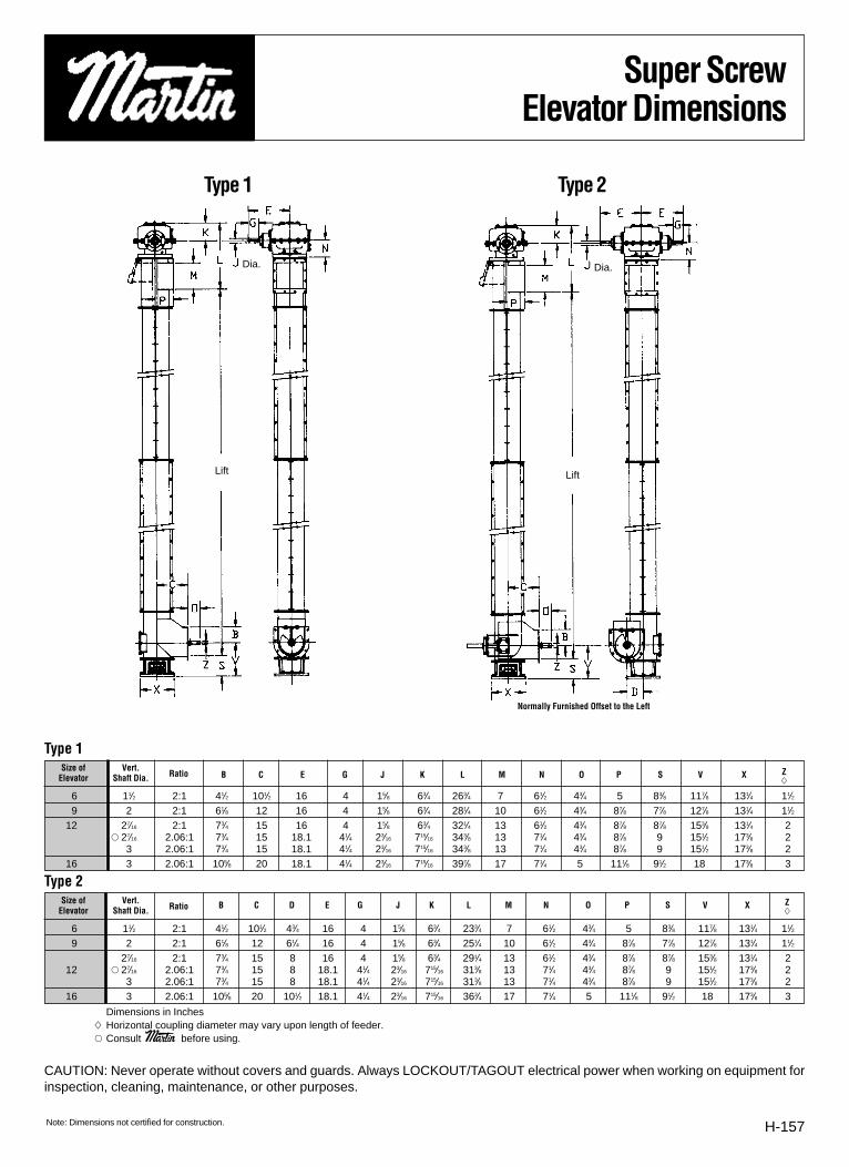
H-157
Super ScrewElevator Dimensions
B C E G J K L M N O P S V X Z�
B C D E G J K L M N O P S V X Z�
6 11⁄2 2:1 41⁄2 101⁄2 43⁄4 16 4 15⁄8 63⁄4 233⁄4 7 61⁄2 43⁄4 5 83⁄8 117⁄8 131⁄4 11⁄29 2 2:1 61⁄8 12 61⁄4 16 4 15⁄8 63⁄4 251⁄4 10 61⁄2 43⁄4 87⁄8 77⁄8 127⁄8 131⁄4 11⁄2
27⁄16 2:1 73⁄4 15 8 16 4 15⁄8 63⁄4 291⁄4 13 61⁄2 43⁄4 87⁄8 87⁄8 153⁄8 131⁄4 212 � 27⁄16 2.06:1 73⁄4 15 8 18.1 41⁄4 23⁄16 715⁄16 313⁄8 13 71⁄4 43⁄4 87⁄8 9 151⁄2 173⁄8 2
3 2.06:1 73⁄4 15 8 18.1 41⁄4 23⁄16 715⁄16 313⁄8 13 71⁄4 43⁄4 87⁄8 9 151⁄2 173⁄8 216 3 2.06:1 105⁄8 20 101⁄2 18.1 41⁄4 23⁄16 715⁄16 363⁄4 17 71⁄4 5 111⁄8 91⁄2 18 173⁄8 3
6 11⁄2 2:1 41⁄2 101⁄2 16 4 15⁄8 63⁄4 263⁄4 7 61⁄2 43⁄4 5 83⁄8 117⁄8 131⁄4 11⁄29 2 2:1 61⁄8 12 16 4 15⁄8 63⁄4 281⁄4 10 61⁄2 43⁄4 87⁄8 77⁄8 127⁄8 131⁄4 11⁄2
12 27⁄16 2:1 73⁄4 15 16 4 15⁄8 63⁄4 321⁄4 13 61⁄2 43⁄4 87⁄8 87⁄8 153⁄8 131⁄4 2� 27⁄16 2.06:1 73⁄4 15 18.1 41⁄4 23⁄16 715⁄16 343⁄8 13 71⁄4 43⁄4 87⁄8 9 151⁄2 173⁄8 2
3 2.06:1 73⁄4 15 18.1 41⁄4 23⁄16 715⁄16 343⁄8 13 71⁄4 43⁄4 87⁄8 9 151⁄2 173⁄8 216 3 2.06:1 105⁄8 20 18.1 41⁄4 23⁄16 715⁄16 397⁄8 17 71⁄4 5 111⁄8 91⁄2 18 173⁄8 3
CAUTION: Never operate without covers and guards. Always LOCKOUT/TAGOUT electrical power when working on equipment forinspection, cleaning, maintenance, or other purposes.
Dimensions in Inches� Horizontal coupling diameter may vary upon length of feeder.� Consult Martin before using.
Type 1
Type 2
Type 1 Type 2
Normally Furnished Offset to the Left
Size of Vert.RatioElevator Shaft Dia.
Size of Vert.RatioElevator Shaft Dia.
Lift Lift
Dia. Dia.
Note: Dimensions not certified for construction.

H-158
Modular Plastic ScrewConveyors
Section VIV
Another Martin patented Innovation. We’ll give your customers another reason to give youtheir business.
*Conveyors shown without cover for illustration purposes only. Please follow manufacturing safety guidelines when operating conveyors.
• Plastic modules consist of a helical flight spi-raling once around a hollow square hub.
• Eliminates need to spot or continuously weldmetal flights to shaft.
• Polyurethane - used where impact/abrasivewear is a problem. Lab tests show it up to 3times more wear resistant than carbon orstainless steel in certain applications.
• All-plastic material does not corrode, is imper-vious to acids, caustics and other chemicals.
• Durable, lightweight injection-molded modulesstack on square tube.
• Polypropylene - general purpose material for
high temperature service.
• FDA approved for food contact.
• Highly resistant to corrosion.
• Modules are individually replaceable withoutwelding or burning.
• Assembled conveyor is comparatively light-weight, easier to handle, and bearing life isprolonged.
• Polyethylene - general purpose material. FDAapproved for food contact.
• Good abrasive and excellent corrosion resis-tance in a wide temperature range.
• Slick surface simplifies cleaning.

H-159
Warning & SafetyReminder
WARNING & SAFETY REMINDERSafety must be considered a basic factor in
machinery operation at all time. Most accidents
are the results of carelessness or negligence.
All rotating power transmission products are
potentially dangerous and must be guarded by
the contractor, installer, purchaser, owner, and
user as required by applicable laws, regula-
tions, standards, and good safety practice.
Additionally specific information must be
obtained from other sources including the lat-
est editions of American Society of Mechanical
Engineers; (ANSI) Safety Code. A copy of this
standard may be obtained from the American
Society of Mechanical Engineers at 345 East
47th Street, New York, NY 10017 (212-705-
7722).
It is the responsibility of the contractor, installer,
purchaser, owner, and user to install, maintain,
and operate the parts or components manufac-
tured and supplied by Martin Sprocket & Gear,
Inc., in such a manner as to comply with the
Williams-Steiger Occupational Safety Act and
with all state and local laws, ordinances, regula-
tions, and the American National Standard
Institute Safety Code.
CAUTIONGuards, access doors, and covers must be securley fastened before operatingany equipment.
If parts are to be inspected, cleaned, observed, or general maintenance performed,
the motor driving the part or components is to be locked out electrically in
such a manner that it cannot be started by anyone, however remote from the
area. Failure to follow these instructions may result in personal injury or property dam-
age.
WARNINGWarning: Static Electricity
Static Electricity may accumulate on modular plastic conveyor screws which carry
non-conductive materials and may produce an electrical spark. Do Not Use to
Convey Non-Conductive Materials in a Combustible Environment.

H-160
Modular Plastic ScrewConveyors - Design Data
Martin Solutionsto Screw ConveyorProblems
• Currently available in 6”, 9” and 12”diameters, in right hand only.
• Assembled conveyors compatiblewith CEMA standards; easily retro-fitted.
• Flight modules available in polyeth-ylene, polypropylene, andpolyurethane, each with character-istics to fill specific needs (seeTechnical Data).
• Flights and hubs are integrallymolded, resulting in consistentdiameter, pitch and thickness witha uniform, smooth finish.
• Plastic modules eliminate metalcontamination to food.
• Assembled conveyor is light inweight, is safe andeasy to handle; bear-ing life is prolonged.
• Plastic flights mayoperate at close clear-ances, or when con-veying many materials,directly on the troughwithout danger ofmetal contamination.
• Modules are individual-ly replaceable.
• Balance is excellentallowing high speedoperation.
F
CD
E B E
D
A
�A. All-plastic screw module�B. Square metal tube�C. Standard coupling tail and
drive shaft�D. Retainer ring and washer�E. Recessed thrust pin�F. Close coupling shaft �
THRUST PIN HOLE
END OF PLASTIC FLIGHTS
SOURCE METAL TUBE
COUPLING BOLT HOLES
To recieve output shaft from�reducer or customer's drive shaft
EXTERNAL ADAPTOR FOR STANDARD INDUSTRIAL CONSTRUCTION
6"
PITCHSHAFT�DIAMETER
CONVEYOR�DIAMETER
MOUNTED SCREW CONVEYOR
�DIAMETER� FULL� SHORT� FLIGHT� OUTSIDE� INSIDE��� PITCH� PITCH� THICKNESS� HUB� HUB�� 6"� 9.05"� 4.53"� .25"� 2.51"� 2.03"�� 9"� 9.05"� 4.53"� .25"� 2.51"� 2.03"�� 12"� 11.72"� 5.86"� .34"� 3.17"� 2.53"�� 14"� NOT CURRENTLY AVAILABLE�� 16"� NOT CURRENTLY AVAILABLE�
RETAINING �RING
WASHER
SQUARE PORTION OF SHAFTINTERIOR�
THRUST PIN
SHAFT�EXTENSION
DRIVE OR TAIL SPECIFIED LENGTH
PLASTIC MODULE
END CONSTRUCTION
SQUARE�METAL TUBE
MODULES
PITCH
FLIGHT
HUB
DIA
ME
TER
FLIGHT THICKNESS
� DIAMETER� AVAILABLE� WEIGHT PER FOOT��� SHAFTS� FULL PITCH � SHORT PITCH�� 6"� 1-1/2", 2"� 4.1 lb� 4.3 lb�� 9"� 1-1/2", 2"� 4.5 lb� 5.2 lb�� 12"� 2", 2-7/16" � 8.0 lb� 9.5 lb�� 14"� NOT CURRENTLY AVAILABLE�� 16"� NOT CURRENTLY AVAILABLE�Weights shown as for polyethylene or polypropylene on stainless �steel tube, polyurethane approximately 10% heavier.
The Martin Screw Conveyor System consists of plastic modules stacked on asquare metal tube. A shaft is inserted at each tube end and secured by arecessed pin. Modules are secured at tube ends by retainer rings and washers.

CUBIC FEET PER HOUR PER R.P.M. FULL PITCH HORIZONTAL
DIAMETER PITCH CONVEYOR LOADFULL 45% 30%
6” 9” 5.72 2.75 1.729” 9” 16.73 7.53 5.02
12” 12” 39.27 17.67 11.7814” 14” NOT CURRENTLY AVAILABLE16” 16” NOT CURRENTLY AVAILABLE
Screw Conveyor Capacities
DIA. SHAFT RATINGS FOR CARBON STEEL SHAFT AND TUBE50 R.P. M. 75 R.P.M. 100 R.P.M. 150 R.P.M.
6”-9” 1-1/2” 3.4 5.1 6.8 10.1
6”-9” 2” 5.6 8.4 11.2 16.8
12” 2” 8.0 12.0 16.0 24.0
12” 2-7/16” 9.1 13.6 18.2 27.3
14” 2-7/16” NOT CURRENTLY AVAILABLE
14” 3” NOT CURRENTLY AVAILABLE
16” 3” NOT CURRENTLY AVAILABLE
POLYETHYLENE POLYPROPYLENE POLYURETHANE
Yes Yes No
Good Fair Excellent
Excellent Excellent Good
Good Fair Excellent
-60º to +150º F -40º to +220º F -20º to +150º
Excellent Good Good
FDA Approved
Abrasive Resistance
Corrosive Resistance
Impact Resistance
Temperature Limit
Release
Horsepower Ratings
H-161
Technical & DesignData
NOTE: The above limitations are based on Martin modular plastic con-struction throughout. The use of coupling bolts, as required for an exter-nal adaptor, may reduce horsepower capacity.
Materials of Construction
DIA. SHAFT TYPE OF INTERMEDIATE BEARINGWOOD, NYLATRON, BRONZE CLOSE COUPLED*
6” 1-1/2” 165 909” 1-1/2” 165 809” 2” 150 8012” 2” 145 7012” 2-7/16” 140 7014” 2-7/16” NOT CURRENTLY AVAILABLE14” 3” NOT CURRENTLY AVAILABLE16” 3” NOT CURRENTLY AVAILABLE
Maximum Recommended ConveyorSpeed / Horizontal Operation / R.P.M.
Note: Release pertains to the capability of conveying “sticky” products.
* Close coupled limitations apply to screw lengths over 12 ft. (for 6” and9” dia.) or 15 ft. (for 12” dia). For longer lengths or units without intermedi-ate bearing supports, locate end bearing no more than 3-1/8” (for 6”size); 4-5/8” (for 9” size); or 6-1/8” (for 12” size); centers above the insidebottom of the conveyor trough.
Design Data for Bonded ConstructionBonded Construction is used in the handling of a finished food prod-
uct or for the conveying of any product in which it is necessary to guardagainst material entering the internal clearances between the modulesor into the inside of the square tube.
The hubs of the individual modules are heat fused together, the endsof the flights may be fused or may be cut to create a “clean out” gap,
usually 1/8” to 1/4” wide. The ends are capped and fitted with an “O” ringto seal around the shaft. The cap may be of alternate construction asdetailed below.
Bonded Construction has USDA acceptance for use as a componentpart of food processing equipment in federally inspected meat and poul-try processing plants.
PLASTIC MODULE
SQUARE�METAL�TUBE
FLAT END�CAP
RETAINING RING�AT FEED END OF�EACH CONVEYOR�SCREW
SPECIFIED CONVEYOR LENGTH�
AT MAXIMUM TEMPERATURE
DRIVE, TAIL OR COUPLING�
SHAFT EXTENSION
PLASTIC MODULE
SQUARE�METAL�TUBE EXTENDED�
END CAP
TROUGH�END�
PLATE
RETAINING RING�AT FEED END OF�EACH CONVEYOR�SCREW
SPECIFIED CONVEYOR LENGTH�
AT MAXIMUM TEMPERATURE
DRIVE OR TAIL�
SHAFT EXTENSION4"
FLAT END CAPSFlat End Caps are the basic construction for conveying finished foodproducts. Drive and Tail End Shafts are shipped factory installed. Ifused with coupling shafts, the thrust bearing must be at the feed endof the conveyor assembly. Retaining ring may be eliminated in someapplications depending upon length and temperature involved.
EXTENDED END CAPSExtended End Caps are used in the handling of products whichrequire a total elimination of cracks and crevices on the conveyorscrew. This precludes the use of coupling shafts and therefore limitsthe unit to one conveyor length, a maximum of 20 feet. Retainer ringsand shafts are entirely outside the product area. Drive and Tail EndShafts are shipped factory installed.

H-162
Shaftless ScrewConveyors
Section X
*Conveyors shown without cover for illustration purposes only. Please follow manufacturing safety guidelines when operating conveyors.

H-163
Shaftless ScrewConveyors
Typical ApplicationsRendering
• Poultry Processing • Meat Processing • Fish Processing• Chicken Feathers • Whole Carcasses • Animal Waste • Fish/Animal Bones
Pulp & Paper, Gypsum Board, Particle Board• Lime Mud • Oversized Wood Chips • Hogged Bark • Shavings
Agriculture• Fertilizer • Corn Gluten • Sugar Beets/Cane Processing • Chopped Hay
Hospital Waste Processing, Recycle Plants• Shredded Cans • Bottles • Paper • Medical Disposables
Wine & Beverage Industries• Grape Skins • Stems • Pumice • Fruit Peels
Waste Water • Solid Waste Treatment• Sludge • Grit • Screenings • Solids Removal
Chemical & Heavy Industrial• Ash • Recycle Batteries • Carbon Black • Shredded Tires
FEATURE FUNCTION BENEFITContinuous Flight Eliminate Hangers Reduces Maintenance
Costs
3/4”-1” Flight Long Lasting Increases Uptime
No Tail Seals or Tail Bearings Use Blind End Plate Reduces Maintenance Costs
Cold Formed Flight High Brinell Longer Life
Eliminate Buildup On Pipe Lower Maintenance/Operation Costs
No Center Pipe Required Can Handle Particle Sizes Up To 90% Of Spiral O.D. Increases Screw
Allows Higher Trough Loading Capacity
(45%-95%)
Side Inlet Feeding No Vertical Transition Necessary Lower Installation CostReduces Headroom

H-164
Warning &Safety Reminder
Martin—Conveyor Division does not installconveyor; consequently it is the responsibility of thecontractor, installer, owner and user to install, main-
tain and operate the conveyor, components andconveyor assemblies in such a manner as to complywith the Williams-Steiger Occupational Safety and
Health Act and with all state and local laws andordinances and the American National Standard
Institute (ANSI) safety code.In order to avoid an unsafe or hazardous condi-
tion, the assemblies or parts must be installed andoperated in accordance with the following minimumprovisions.1. Conveyors shall not be operated unless all covers
and/or guards for the conveyor and drive unit arein place. If the conveyor is to be opened forinspection cleaning, maintenance or observation,the electric power to the motor driving the convey-or must be LOCKED OUT in such a manner thatthe conveyor cannot be restarted by anyone;however remote from the area, until conveyorcover or guards and drive guards have beenproperly replaced.
2. If the conveyor must have an open housing as acondition of its use and application, the entire con-veyor is then to be guarded by a railing or fence inaccordance with ANSI standard B20.1-1993, withspecial attention given to section 6.12.
3. Feed openings for shovel, front loaders or othermanual or mechanical equipment shall beconstructed in such a way that the conveyor open-ing is covered by a grating. If the nature of thematerial is such that a grating cannot be used,then the exposed section of the conveyor is to beguarded by a railing or fence and there shall be awarning sign posted.
4. Do not attempt any maintenance or repairs of theconveyor until power has been LOCKED OUT.
5. Always operate conveyor in accordance withthese instructions and those contained on thecaution labels affixed to the equipment.
6. Do not place hands or feet in the conveyor.7. Never walk on conveyor covers, grating or
guards.8. Do not use conveyor for any purpose other than
that for which it was intended.9. Do not poke or prod material into the conveyor
with a bar or stick inserted through the openings.10. Keep area around conveyor drive and control
station free of debris and obstacles.11. Always regulate the feeding of material into the
unit at a uniform and continuous rate.12. Do not attempt to clear a jammed conveyor until
power has been LOCKED OUT.13. Do not attempt field modification of conveyor or
components.14. Screw conveyors are not normally manufactured
or designed to handle materials that arehazardous to personnel. These materials whichare hazardous include those that are explosive,flammable, toxic or otherwise dangerous topersonnel. Conveyors may be designed to handlethese materials. Conveyors are not manufacturedor designed to comply with local, state or federalcodes for unfired pressure vessels. If hazardousmaterials are to be conveyed or if the conveyor isto be subjected to internal or external pressure,
—Conveyor Division should be consultedprior to any modifications.
—Conveyor Division insists that disconnect-ing and locking out the power to the motor driving theunit provides the only real protection against injury.Secondary safety devices are available; however,the decision as to their need and the type requiredmust be made by the owner-assembler as we haveno information regarding plant wiring, plant environ-ment, the interlocking of the screw conveyor withother equipment, extent of plant automation, etc.
Other devices should not be used as a substitute forlocking out the power prior to removing guards orcovers. We caution that use of the secondarydevices may cause employees to develop a falsesense of security and fail to lock out power beforeremoving covers or guards. This could result in aserious injury should the secondary device fail ormalfunction.
There are many kinds of electrical devices forinterlocking of conveyors and conveyor systemssuch that if one conveyor in a system or process isstopped other equipment feeding it, or following itcan also be automatically stopped.
Electrical controls, machinery guards, railings,walkways, arrangement of installation, training ofpersonnel, etc., are necessary ingredients for a safeworking place. It is the responsibility of the con-tractor, installer, owner and user to supplement thematerials and services furnished with these necessaryitems to make the conveyor installation comply withthe law and accepted standards.
Conveyor inlet and discharge openings aredesigned to connect to other equipment or machineryso that the f low of material into and out of theconveyor is completely enclosed.
One or more caution signs (as illustrated below)are attached to conveyor housings, conveyor coversand screw elevator housings. Please order replace-ment caution labels should the labels attached to thisequipment become illegible.
The label shown below has been reduced insize. The actual size is printed next to the label. Formore detailed instructions and information, pleaserequest a free copy of our “Screw Conveyor Safety,Installation, Operation, Maintenance Instructions.”
The Conveyor Equipment Manufacturer’sAssociation (CEMA) has produced an audio-visualpresentation entitled “Safe Operation of ScrewConveyors, Drag Conveyors, and Bucket Elevators.”
—Conveyor Division encourages acquisitionand use of this source of safety information.
WARNING
CVS930011
Exposed screw and�moving parts can�cause severe injury��LOCK OUT POWER�before removing�cover or servicing
CHS930001
Exposed moving �parts can cause �severe injury��LOCK OUT POWER�before removing�guard
ACTUAL SIZE 6" x 3"
PROMINENTLY DISPLAY IN WORK AREAS
ACTUAL SIZE 5" x 21/2"

H-165
Size and Capacity
Specifications:Type of Steel Carbon Steel • High Brinell Carbon Steel • Stainless Steel
Capacity Up to 17,000 CFHDiameter 6” to 30” (and Larger)
Pitches Full, 2/3, 1/2Trough CEMA Standards
Options UHMW Liners, AR Liners, Rider Bars, Drive End SealsAdvantages Spanning longer distances without intermediate bearings Transport sticky products and large lumps.
NOM. A B C CFH* CFH* CFH* MAXDIA. Dia. Inside Pitch Full Pitch 2/3 Pitch 1/2 Pitch RPM
6 6 7 6 65 43 33 25
9 9 10 9 224 149 112 25
10 10 11 10 307 205 154 25
12 12 13 12 530 353 265 25
14 14 15 14 842 561 421 25
16 16 17 16 1256 837 628 25
18 18 19 18 1789 1193 895 25
20 20 21 20 2455 1637 1228 25
24 24 25 24 4240 2827 2120 25
30 30 31 30 8283 5522 4142 25
45% Trough Loading 95% Trough LoadingNOM. A B C CFH* CFH* CFH* MAXDIA. Dia. Inside Pitch Full Pitch 2/3 Pitch 1/2 Pitch RPM
6 6 7 6 140 93 70 25
9 9 10 9 472 315 236 25
10 10 11 10 648 432 324 25
12 12 13 12 1119 746 560 25
14 14 15 14 1777 1185 889 25
16 16 17 16 2652 1766 1326 25
18 18 19 18 3776 2517 1888 25
20 20 21 20 5180 3453 2590 25
24 24 25 24 8950 5967 4475 25
30 30 31 30 17485 11657 8743 25
*CFH = Cubic Feet per hour. -**ALL DIMENSIONS SHOWN IN INCHES.
NOM WIDTH CFH* CFH* CFH* MAXDIA. D Full Pitch 2/3 Pitch 1/2 Pitch RPM
6 28 352 235 176 159 40 1192 795 596 1510 44 1636 1091 818 1512 52 2824 1883 1412 1514 60 4488 2992 2244 1516 68 6700 4467 3350 1518 76 9540 6360 4770 1520 84 13088 8725 6544 1524 100 22612 15075 11306 1530 124 44160 29440 22080 15
Quad Screw Feeder 95% Trough Loading
D
WIDTH
20’-0” M
ax Length
(Consult F
actory For
Longer Le
ngths)
*CFH = Cubic Feet per hour. -**ALL DIMENSIONS SHOWN IN INCHES.
B
A A
C
*Conveyors shown without cover for illustration purposes only. Please follow manufacturing safety guidelines when operating conveyors.

H-166
CUSTOMER:______________________________________________________________________ DATE PROPOSAL DUE: _________________________________
ADDRESS:______________________________________________________________________________________________________________________________
CONTACT: _______________________________________________________________________ PHONE # _____________________________________________
SCREW DESCR: ____ QTY. ___________ ″ DIA. × LONG (C INLET TO C DISCH.) (OVERALL) � HORIZ. � INCL. _____________° � DECL. _____________°
CAPACITY: ________________________ (CFH) (LBS/HR) (TPH) (MTPH) (BPH)
MATERIAL:__________________________________ DENSITY ____________________________ LBS/FT3 TEMP _____°F MOISTURE _________________%
LUMPS: MAX SIZE _____ IN LUMP CLASS: (Lump % of Total; I - 10%, II - 25%, III - 95%)
INSTALLATION: � INDOORS � OUTDOORS � NEW � REPLACEMENT � MAT’L OF CONSTR.: � MILD STEEL � T304 � T316 � HD GALV � OTHER _____
IS IT? � FEEDER � CONVEYOR IS FEED? � FLOOD LOAD � UNIFORM
FED BY: ___________________________ INLET SIZE: ___________________________________ DISCHARGES TO:______________________________________
DRIVE: (SCREW CONVEYOR DRIVE) (SHAFT MOUNT) (OTHER):_________________________________________________________________________________
NOTES: ________________________________________________________________________________________________________________________________
________________________________________________________________________________________________________________________________________ _ _ _ _ _ _ _ _ _ _ _ _ _ _ _ _ _ _ _ _ _ _ _ _ _ _ _ _ _ _ _ _ _ _ _ _ _ _ _ _ _ _ _ _ _ _ _ _ _ _ _ _
THROUGH: STYLE _________________ THK.______________________ COUPL. BOLTS: ________________________________________________________
DISCHARGE: TYPE ________________ QTY.______________________ HANGER: STYLE _______________________________________________________
GATES: TYPE _____________________ QTY.______________________ HANGER BRG.: TYPE ____________________________________________________
THROUGH END TYPE: TAIL ____________________________________ COVER: STYLE ______________________________ THK.______________________
THROUGH END TYPE: HEAD___________________________________ COVER FASTENERS: TYPE ______________________________________________
BEARING TYPE: TAIL______________ HEAD______________________ INLETS: STYLE ______________________________ QTY.______________________
SEAL TYPE: TAIL _________________ HEAD______________________ GASKETS: TYPE __________________________________ THK. _________________
SCREW: DIA. ________ (RH) (LH) PITCH __________ THK. __________ DRIVE _______________________ HP AT ______________________________ RPM
___________________________________________________________ MOTOR: _________________________________ MOTOR MOUNT _______________
___________________________________________________________ REDUCER: ____________________________________________________________
___________________________________________________________ V-BELT/CHAIN: _________________________________________________________
NOTES: ________________________________________________________________________________________________________________________________
_______________________________________________________________________________________________________________________________________
SKETCH — (SHOW FEEDER INLET SIZE AND LOCATION, DRIVE LOCATION, ETC.)
PAGE ___________ OF _____________ PREPARED BY_____________________________________________________________ DATE __________________
Screw ConveyorData Sheet

H-167
Screw ConveyorData Sheet
CUSTOMER:______________________________________________________________________ DATE PROPOSAL DUE: _________________________________
ADDRESS:______________________________________________________________________________________________________________________________
CONTACT: _______________________________________________________________________ PHONE # _____________________________________________
SCREW DESCR: ____ QTY. __________ ″ DIA. × __________ LONG (C INLET TO C DISCH.) (OVERALL) � HORIZ. � INCL. __________° � DECL. _____________°
CAPACITY: ________________________ (CFH) (LBS/HR) (TPH) (MTPH) (BPH)
MATERIAL:__________________________________ DENSITY ____________________________ LBS/FT3 TEMP _____°F MOISTURE _________________%
LUMPS: MAX SIZE _____ IN LUMP CLASS: (Lump % of Total; I - 10%, II - 25%, III - 95%)
INSTALLATION: � INDOORS � OUTDOORS � NEW � REPLACEMENT � MAT’L OF CONSTR.: � MILD STEEL � T304 � T316 � HD GALV � OTHER _____
IS IT? � FEEDER � CONVEYOR IS FEED? � FLOOD LOAD � UNIFORM
FED BY: ___________________________ INLET SIZE: ___________________________________ DISCHARGES TO:______________________________________
DRIVE: (SCREW CONVEYOR DRIVE) (SHAFT MOUNT) (OTHER):_________________________________________________________________________________
NOTES: ________________________________________________________________________________________________________________________________
________________________________________________________________________________________________________________________________________ _ _ _ _ _ _ _ _ _ _ _ _ _ _ _ _ _ _ _ _ _ _ _ _ _ _ _ _ _ _ _ _ _ _ _ _ _ _ _ _ _ _ _ _ _ _ _ _ _ _ _ _
THROUGH: STYLE _________________ THK.______________________ COUPL. BOLTS: ________________________________________________________
DISCHARGE: TYPE ________________ QTY.______________________ HANGER: STYLE _______________________________________________________
GATES: TYPE _____________________ QTY.______________________ HANGER BRG.: TYPE ____________________________________________________
THROUGH END TYPE: TAIL ____________________________________ COVER: STYLE ______________________________ THK.______________________
THROUGH END TYPE: HEAD___________________________________ COVER FASTENERS: TYPE ______________________________________________
BEARING TYPE: TAIL______________ HEAD______________________ INLETS: STYLE ______________________________ QTY.______________________
SEAL TYPE: TAIL _________________ HEAD______________________ GASKETS: TYPE __________________________________ THK. _________________
SCREW: DIA. ________ (RH) (LH) PITCH __________ THK. __________ DRIVE _______________________ HP AT ______________________________ RPM
___________________________________________________________ MOTOR: _________________________________ MOTOR MOUNT _______________
___________________________________________________________ REDUCER: ____________________________________________________________
___________________________________________________________ V-BELT/CHAIN: _________________________________________________________
NOTES: ________________________________________________________________________________________________________________________________
_______________________________________________________________________________________________________________________________________
SKETCH — (SHOW FEEDER INLET SIZE AND LOCATION, DRIVE LOCATION, ETC.)
PAGE ___________ OF _____________ PREPARED BY_____________________________________________________________ DATE __________________

TYPE: � CENTRIFUGAL � CONTINUOUS � GRAIN TYPE � OTHER___________________
� CHAIN � BELT SPECS. _________________________________________________
DRIVE: _____________ HP AT _____________ RPM REDUCER _________________________
SPKTS/SHEAVES _______________ CHAIN/V-BELTS _________________________________
_______________ BACKSTOP ____________________________________________________
INLET: � STANDARD � SPECIAL ________________________________________________
DISCHARGE: � STANDARD � 45°
SAFETY CAGE: � YES � NO LADDER: LGTH _____________________________________
HEAD PLATFORM: � STANDARD SIZE � SPECIAL __________________________________
INT. PLATFORM � STANDARD SIZE � SPECIAL ____________________________________
THICKNESS: HEAD ____________ BOOT ____________ INT. ___________________________
TAKEUP: � HEAD � BOOT � SCREW � GRAVITY
SEALS: � STANDARD � SPECIAL _____________ VENTS: SIZE ___________ QTY _______
________________________________________________________PAINT: ________________________________________________________________________
H-168
Bucket ElevatorData Sheet
CUSTOMER:______________________________________________________________________ DATE QUOTE DUE:_____________________________________
ADDRESS:______________________________________________________________________________________________________________________________
CONTACT: _______________________________________________________________________ PHONE # _____________________________________________
BUCKET ELEVATOR: (CTRS/LIFT) ___________________________ DESCR. _______________________________________________________________________
_______________________________________________________________________________________________________________________________________
CAPACITY: ________________________ (CFH) (LBS/HR) (TPH) (MTPH) (BPH)
MATERIAL:__________________________________ DENSITY_____________________________ LBS/FT3 TEMP _____°F MOISTURE _________________%
LUMPS: MAX SIZE _____ IN LUMP CLASS: (Lump % of Total; I - 10%, II - 25%, III - 95%)
FED BY: _________________________________________________DISCHARGES TO: ______________________________________________________________
MAT’L OF CONSTR: � MILD STEEL � T304 � T316 � H.D. GALV. � OTHER
INSTALLATION: � NEW � REPLACEMENT � INDOORS � OUTDOORS
DRIVE: (SHAFT MOUNT) (FOOT MOUNTED GEAR REDUCER) (OTHER): _____________________________________________ � V-BELTS � CHAIN � GUARD
___________________MOTOR: � TEFC � X-PROOF � MAC � OTHER ___________________BACKSTOP: � SHAFT � INTEGRAL TO REDUCER � OTHER
________________________________________________________NOTES: _______________________________________________________________________
________________________________________________________________________________________________________________________________________ _ _ _ _ _ _ _ _ _ _ _ _ _ _ _ _ _ _ _ _ _ _ _ _ _ _ _ _ _ _ _ _ _ _ _ _ _ _ _ _ _ _ _ _ _ _ _ _ _ _ _ _
PAGE ___________ OF _____________ PREPARED BY_____________________________________________________________ DATE __________________
Head
Intermediate
Boot
Lift
Cle
anou
t Doo
r

H-169
Bucket ElevatorData Sheet
CUSTOMER:______________________________________________________________________ DATE QUOTE DUE:_____________________________________
ADDRESS:______________________________________________________________________________________________________________________________
CONTACT: _______________________________________________________________________ PHONE # _____________________________________________
BUCKET ELEVATOR: (HEIGHT) _____________________________ DESCR. _______________________________________________________________________
_______________________________________________________________________________________________________________________________________
CAPACITY: ________________________ (CFH) (LBS/HR) (TPH) (MTPH) (BPH)
MATERIAL:__________________________________ DENSITY_____________________________ LBS/FT3 TEMP _____°F MOISTURE _________________%
LUMPS: MAX SIZE _____ IN LUMP CLASS: (Lump % of Total; I - 10%, II - 25%, III - 95%)
FED BY: _________________________________________________DISCHARGES TO: ______________________________________________________________
MAT’L OF CONSTR: � MILD STEEL � T304 � T316 � H.D. GALV. � OTHER
INSTALLATION: � NEW � REPLACEMENT � INDOORS � OUTDOORS
DRIVE: (SHAFT MOUNT) (FOOT MOUNTED GEAR REDUCER) (OTHER): _____________________________________________ � V-BELTS � CHAIN � GUARD
___________________MOTOR: � TEFC � X-PROOF � MAC � OTHER ___________________BACKSTOP: � SHAFT � INTEGRAL TO REDUCER � OTHER
________________________________________________________NOTES: _______________________________________________________________________
________________________________________________________________________________________________________________________________________ _ _ _ _ _ _ _ _ _ _ _ _ _ _ _ _ _ _ _ _ _ _ _ _ _ _ _ _ _ _ _ _ _ _ _ _ _ _ _ _ _ _ _ _ _ _ _ _ _ _ _ _
PAGE ___________ OF _____________ PREPARED BY_____________________________________________________________ DATE __________________
TYPE: � CENTRIFUGAL � CONTINUOUS � GRAIN TYPE � OTHER___________________
� CHAIN � BELT SPECS. _________________________________________________
DRIVE: _____________ HP AT _____________ RPM REDUCER _________________________
SPKTS/SHEAVES _______________ CHAIN/V-BELTS _________________________________
_______________ BACKSTOP ____________________________________________________
INLET: � STANDARD � SPECIAL ________________________________________________
DISCHARGE: � STANDARD � 45°
SAFETY CAGE: � YES � NO LADDER: LGTH _____________________________________
HEAD PLATFORM: � STANDARD SIZE � SPECIAL __________________________________
INT. PLATFORM � STANDARD SIZE � SPECIAL ____________________________________
THICKNESS: HEAD ____________ BOOT ____________ INT. ___________________________
TAKEUP: � HEAD � BOOT � SCREW � GRAVITY
SEALS: � STANDARD � SPECIAL _____________ VENTS: SIZE ___________ QTY _______
________________________________________________________PAINT: ________________________________________________________________________
Head
Intermediate
Boot
Lift
Cle
anou
t Doo
r
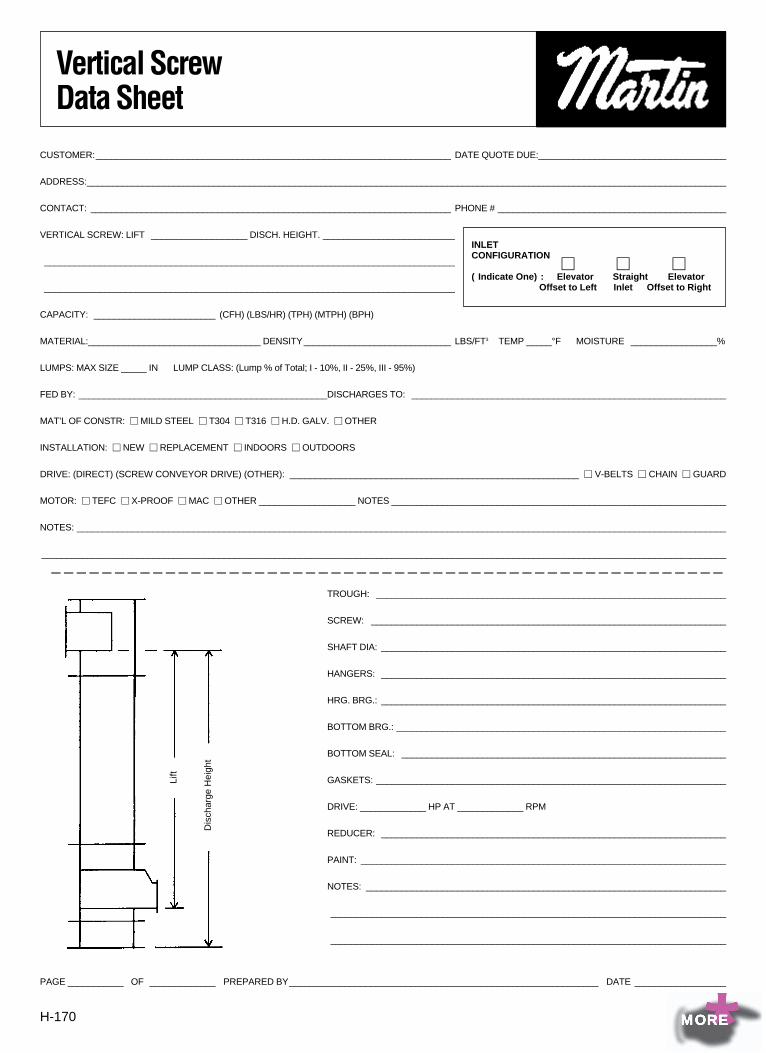
H-170
Vertical ScrewData Sheet
CUSTOMER:______________________________________________________________________ DATE QUOTE DUE:_____________________________________
ADDRESS:______________________________________________________________________________________________________________________________
CONTACT: _______________________________________________________________________ PHONE # _____________________________________________
VERTICAL SCREW: LIFT ___________________ DISCH. HEIGHT. __________________________
_________________________________________________________________________________
_________________________________________________________________________________
CAPACITY: ________________________ (CFH) (LBS/HR) (TPH) (MTPH) (BPH)
MATERIAL:__________________________________ DENSITY_____________________________ LBS/FT3 TEMP _____°F MOISTURE _________________%
LUMPS: MAX SIZE _____ IN LUMP CLASS: (Lump % of Total; I - 10%, II - 25%, III - 95%)
FED BY: _________________________________________________DISCHARGES TO: ______________________________________________________________
MAT’L OF CONSTR: � MILD STEEL � T304 � T316 � H.D. GALV. � OTHER
INSTALLATION: � NEW � REPLACEMENT � INDOORS � OUTDOORS
DRIVE: (DIRECT) (SCREW CONVEYOR DRIVE) (OTHER): _________________________________________________________ � V-BELTS � CHAIN � GUARD
MOTOR: � TEFC � X-PROOF � MAC � OTHER ___________________ NOTES __________________________________________________________________
NOTES: ________________________________________________________________________________________________________________________________
________________________________________________________________________________________________________________________________________ _ _ _ _ _ _ _ _ _ _ _ _ _ _ _ _ _ _ _ _ _ _ _ _ _ _ _ _ _ _ _ _ _ _ _ _ _ _ _ _ _ _ _ _ _ _ _ _ _ _ _ _
PAGE ___________ OF _____________ PREPARED BY_____________________________________________________________ DATE __________________
TROUGH: _____________________________________________________________________
SCREW: ______________________________________________________________________
SHAFT DIA: ____________________________________________________________________
HANGERS: ____________________________________________________________________
HRG. BRG.: ____________________________________________________________________
BOTTOM BRG.: _________________________________________________________________
BOTTOM SEAL: ________________________________________________________________
GASKETS: _____________________________________________________________________
DRIVE: _____________ HP AT _____________ RPM
REDUCER: ____________________________________________________________________
PAINT: ________________________________________________________________________
NOTES: _______________________________________________________________________
______________________________________________________________________________
______________________________________________________________________________
INLETCONFIGURATION
� � �(Indicate One): Elevator Straight Elevator
Offset to Left Inlet Offset to Right
Lift
Dis
char
ge H
eigh
t
*MORE