gujarat energy transmission corporation ltd. office/000001/npshah-i… · gujarat energy...
TRANSCRIPT

GETCO/E/06TS – ISO 011/R2 APR09
SEAL OF THE FIRM SIGNATURE OF BIDDER
Page 1 of 33
GUJARAT ENERGY TRANSMISSION
CORPORATION LTD.
SARADAR PATEL VIDYUT BHAVAN, RACE COURSE, BARODA – 390 007.
TECHNICAL SPECIFICATION
FOR
66 kV ISOLATORS & ISOLATOR – CUM – EARTHING SWITCHES
GETCO/E/06TS – ISO 011/R2 APR09

GETCO/E/06TS – ISO 011/R2 APR09
SEAL OF THE FIRM SIGNATURE OF BIDDER
Page 2 of 33
SPECIAL INSTRUCTIONS TO BIDDER Please read following instructions carefully before submitting your bid. 1. All the drawings, i.e. elevation, side view, plan, cross sectional view etc., in
AutoCAD format and manuals in PDF format, for offered item shall be submitted. Also the hard copies as per specification shall be submitted.
2. The bidder shall submit Quality Assurance Plan with the technical bid. 3. The bidder shall have to submit all the required type test reports for the offered
item. In absence of this, the evaluation shall be carried out accordingly as non-submission of type test reports.
4. The bidder must fill up all the points of GTP for offered item/s. Instead of
indicating “refer drawing, or as per IS/IEC”, the exact value/s must be filled in. 5. All the points other than GTP, which are asked to confirm in technical
specifications must be submitted separately with the bid. 6. The bidder is required to impart training in view of manufacture, assembly,
erection, operation and maintenance for offered item, at his works, to the person/s identified by GETCO, in the event of an order, free of cost. The cost of logistics will be bear by GETCO.
7. Please note that the evaluation will be carried out on the strength of content of
bid only. No further correspondence will be made. 8. The bidder shall bring out all the technical deviation/s only at the specified
annexure.

GETCO/E/06TS – ISO 011/R2 APR09
SEAL OF THE FIRM SIGNATURE OF BIDDER
Page 3 of 33
QUALIFYING REQUIREMENT DATA (For Supply)
Bidder to satisfy all the following requirements. 1) The bidder shall be Original Equipment Manufacturer (OEM).
The offered equipment have to be designed, manufactured and tested as per relevant IS/IEC with latest amendments.
2) The minimum requirement of manufacturing capacity of offered
type, size and rating of equipment shall be SEVEN times tender/ bid quantity. The bidder should indicate manufacturing capacity by submitting latest updated certificate of a Chartered Engineer (CE).
3) Equipment proposed shall be of similar or higher rating and in
service for a minimum period of THREE (3) years and satisfactory performance certificate in respect of this is to be available and submitted.
4) The bidder should clearly indicate the quantity and Single Value
Contract executed during last FIVE (5) years, for the offered equipment. Bidder should have executed one single contract during last five years for the quantity equivalent to tender / bid.
The details are to be submitted in following format, Sr. No
ITEMS SUPPL
IED TO
ORDER REFERENCE No. &
DATE
ITEMS QUANTITY ORDER FULLY
EXECUTED. YES/NO
STATUS, IF ORDER UNDER
EXECUTION
REMARK
e) Equipment offered shall have Type Test Certificates from accredited
laboratory (accredited based on ISO/IEC Guide 25 / 17025 or EN 45001 by the National accredition body of the country where laboratory is located), as per IEC / IS / technical specification. The type test reports shall not be older than FIVE years and shall be valid up to expiry of validity of offer.
GETCO/E/06TS – ISO 011/R2 APR09
SEAL OF THE FIRM SIGNATURE OF BIDDER
Page 4 of 33
TECHNICAL SPECIFICATION FOR 66 kV ISOLATORS & ISOLATOR – CUM – EARTHING SWITCHES
SECTION – I
GENERAL TECHNICAL REQUIREMENTS
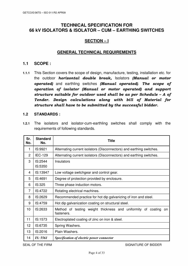
1.1 SCOPE :
1.1.1 This Section covers the scope of design, manufacture, testing, installation etc. for
the outdoor horizontal double break, Isolators (Manual or motor
operated) and earthling switches (Manual operated). The scope of
operation of isolator (Manual or motor operated) and support
structure suitable for outdoor used shall be as per Schedule – A of
Tender. Design calculations along with bill of Material for
structure shall have to be submitted by the successful bidder.
1.2 STANDARDS :
1.2.1 The isolators and isolator-cum-earthling switches shall comply with the
requirements of following standards.
Sr. No.
Standard No.
Title
1 IS:9921 Alternating current isolators (Disconnectors) and earthing switches.
2 IEC-129 Alternating current isolators (Disconnectors) and earthing switches.
3 IS:2544
IS:5350
Insulators
4 IS:13947 Low voltage switchgear and control gear.
5 IS:4691 Degree of protection provided by enclosure.
6 IS:325 Three phase induction motors.
7 IS:4722 Rotating electrical machines.
8 IS:2629 Recommended practice for hot dip galvanizing of iron and steel.
9 IS:4759 Hot dip galvanization coating on structural steel.
10 IS:2633 Method of testing weight thickness and uniformity of coating on fasteners.
11 IS:1573 Electroplated coating of zinc on iron & steel.
12 IS:6735 Spring Washers.
13 IS:2016 Plain Washers.
14 IS: 5561 Specification of electric power connector
GETCO/E/06TS – ISO 011/R2 APR09
SEAL OF THE FIRM SIGNATURE OF BIDDER
Page 5 of 33
1.3 DRAWINGS :
1.3.1 Bidder shall submit the following drawings (in duplicate) along with the offer for scrutiny.
(i) Drawing showing plan, side view and elevation of isolator and earthing switch incorporating mounting dimensions, overall dimensions, weight etc.
(ii) Dimensional drawing for the main switch contact assembly for line and earthing of the isolator.
(iii) Mounting details, operating handle, motor operating box and operating devices. (iv) Details of contacts, hinged terminal contact and main isolator blades. (v) Drawing of isolators supporting structures. (vi) Control wiring/ schematic diagram. (vii) Copies of type test certificates and relevant oscillograms. (viii) Isolator and Earth switch operating mechanism box with accessories and
mechanism. (ix) any other drawings which he considers necessary for giving complete information
about equipment. 1.3.2 After receipt of an order, the successful Bidder shall have to furnish, the following
drawings for approval of the purchaser.
(i) Assembly drawing showing plan, side view and elevation of isolators and earthing switch incorporating mounting dimensions, detailed dimensions, shipping weight, net weight etc.
(ii) Schematic control wiring diagram and interlocking scheme. (iii) Dimensional control for the line and earth side terminals of the isolator. Also,
dimensional drawing of the clamps and connectors. (iv) Location and mounting details of operating handle and operating devices. (v) Drawing giving details of guides and guide bearings (Type, designation,
number, make) to be mounted on isolator supporting structure. (vi) Details of contacts and main isolator blades. (vii) Details of terminal stud. (viii) Drawing & necessary design and fabrication of isolators supporting structure, if
structures are included in the scope of supply. (ix) Drawing showing various positions (close and open) of the isolator. (x) Drawing for support structure. (xi) Drawings of supporting insulators & operating rods insulators. (xii) Name plat details. (xiii) Bill of materials. Supplier shall furnish of three sets of all the drawings pertaining to the equipment along with soft copy for each item as the final submission for approval. 1.4 GENERAL DESIGN FEATURES OF ISOLATORS AND ISOLATOR-CUM-
EARTHING SWITCHES :
1.4.1 The Isolators shall be of double break, outdoor, gang operated type, with blades
rotating in horizontal plane. It should be centre post rotating Turn N Twist
GETCO/E/06TS – ISO 011/R2 APR09
SEAL OF THE FIRM SIGNATURE OF BIDDER
Page 6 of 33
type. The design shall allow for upright mounting, if required, and the Isolators
shall be convertible for right or left hand control with minimum labour and
replacement of parts. The live parts shall be so designed that as far as possible,
sharp points, edges and other corona producing surface are eliminated. Except
for the Insulator caps and bases, all other live parts shall be of anti rusting and
non-corrosive metal. Current carrying parts shall be non-ferrous. Bolts, Screws
and Pins shall be provided with locking arrangement and shall be of materials
specified here in.
1.4.2 Each pole shall have three Pedestal type of insulators' stacks. Necessary
arrangements shall be provided for proper alignment of the contacts. Gang
operated links shall be so designed that all phases shall make and break
simultaneously.
1.4.3 The design of the isolators and isolator-cum-earthing switches shall be provided
for positive control of blades in all positions with minimum mechanical stress on
the insulators. Fixed guides shall be so provided that proper fitting of contacts
shall be obtained, when a blade is out of alignment even by 25 mm in either
direction. All movable parts which may be in correct path shall be shunted by
flexible copper conductor of specified cross-section and capacity, which shall be
furnished under bill of materials.
1.4.4 The length of the handle for manual operation shall not be more than one meter
and shall be stated in the drawing. The rotating parts shall have a smooth
movement.
1.4.5 The clearance of 4000 mm from live parts to plinth shall be considered while
manufacturing of isolators & to decide location of operating mechanism box.
Height of structure of isolator from plinth is to be considered as 3080 mm.
1.4.6 The isolators/earthing switch shall be completed with all parts
that are necessary or essential for efficient & safe operation. Such
part shall be deemed to be within the scope of supply, whether
specifically mentioned or not.
1.4.7 All similar parts shall be interchangeable.
1.4.8 The design of isolator shall be such that no lubrication of any part
is required except at vary infrequent intervals i.e. after every 1000
operations or after 5 years whichever is earlier. All joint in link
mechanism exposed directly to external environment shall be such
materials that they do not call for any periodic lubrication and
will not create jamming or excessive play which can result into
GETCO/E/06TS – ISO 011/R2 APR09
SEAL OF THE FIRM SIGNATURE OF BIDDER
Page 7 of 33
loss of setting of complete isolator or deformation in links and
levers.
1.4.9 Terminal head/stud of isolator arms where conductor will be terminated
shall be strong, robust and shall be adequate to carry rated current and
short-circuit rating of isolator. It should have built in cover to
eliminate deposition of dust or foreign particles.
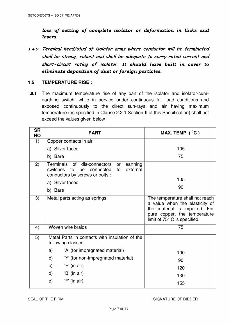
1.5 TEMPERATURE RISE :
1.5.1 The maximum temperature rise of any part of the isolator and isolator-cum-
earthing switch, while in service under continuous full load conditions and
exposed continuously to the direct sun-rays and air having maximum
temperature (as specified in Clause 2.2.1 Section-II of this Specification) shall not
exceed the values given below :
SR NO
PART MAX. TEMP. ( 0C )
1) Copper contacts in air
a) Silver faced
b) Bare
105
75
2) Terminals of dis-connectors or earthing switches to be connected to external conductors by screws or bolts :
a) Silver faced
b) Bare
105
90
3) Metal parts acting as springs. The temperature shall not reach a value when the elasticity of the material is impaired. For pure copper, the temperature limit of 750 C is specified.
4) Woven wire braids 75
5) Metal Parts in contacts with insulation of the following classes :
a) 'A' (for impregnated material)
b) 'Y' (for non-impregnated material)
c) 'E' (in air)
d) 'B' (in air)
e) 'F' (in air)
100
90
120
130
155

GETCO/E/06TS – ISO 011/R2 APR09
SEAL OF THE FIRM SIGNATURE OF BIDDER
Page 8 of 33
SR NO
PART MAX. TEMP. ( 0C )
6) Enamel :
a) Oil base
b) Synthetic in air
100
120
1.6 CONTACTS :
1.6.1 The moving and fixed contacts shall be made of hard drawn electrolytic copper
and shall be heavy duty self-aligning & high pressure type preferably which
applies pressure to the contact surface after the blades are fully closed and
release the pressure before they start to open. High pressure type contacts shall
wipe the contact surface, while opening and closing. The contacts shall be so
designed that wiping action shall not cause scouring or abrasion on the contact
surface. The wiping action shall be sufficient to remove oxide film formed during
the operation of the switches. The pressure shall be developed by rotation of the
entire blade.
1.6.2 The temperature rise of contacts due to the flow of rated short circuit current for a
period of three seconds shall not cause any annealing or welding of the contacts.
1.6.3 The moving contacts shall be capable of withstanding the highest short circuit
current during service. The surface of the contacts shall be smooth and silver
plated, with specified thickness of silver plating.
1.6.4 Current Density:
Current density to be adopted for all part of the Isolator and terminal connector
shall not exceed the following limits
(a) Hollow tube section : Copper – 2.0 A/mm2
: Aluminum–1.25 A/mm2
(b) Other sections & terminal connectors : Copper – 1.60 A/mm2
: Aluminum – 1.0 A/mm2
1.6.5 The arcing contacts, if provided, shall close first and open last so that no damage
is caused due to arcing what so ever to the main contacts. The bidder shall give
full details of such contacts with necessary drawings.
1.6.6 The jaw contacts shall be of copper with silver plating of Min. 20
micron. The contacts shall be accurately machined and self

GETCO/E/06TS – ISO 011/R2 APR09
SEAL OF THE FIRM SIGNATURE OF BIDDER
Page 9 of 33
aligned. Contacts & spring shall be so designed that readjustment
in contact pressure shall not be necessary throughout the life of
Isolator or earthing switch. The jaw contacts shall be with reverse
loop fingers design such that springs shall not carry current &
shall not loose their characteristics due to heating effect. The
contacts shall be backed by Stainless Steel spring and shall be such
that there will always be a positive contact with adequate pressure to give
enough contact surfaces for the passing of the current. The springs provided
should not go out of alignment or get entangled with the male contact during
operation. The details of springs shall be furnished on the G.A. drawing.
1.6.7 The contact shall be self aligning & self cleaning & so designed
that binding cannot occur after remaining closed for prolonged
period of time in a heavily polluted atmosphere.
1.6.8 No undue wear or stuffing shall be evident during mechanical endurance tests.
1.7 OPERATING MECHANISM & CONTROL:
1.7.1 The isolators shall be electrical motor operated and manually
operated. The earthing switches shall be manually operated. The
mechanism shall provide quick, simple & effective operation.
Single person shall be able to operate the isolator, earthing switch
without undue effort. The height of the handle above the plinth
shall be 1000 mm. This will be stated in the drawing. The operating
mechanism shall have smooth movement and shall be so designed that all the
three blades are in positive control throughout the entire cycle of operation.
1.7.2 The minimum size of box shall be as follow:
i) Motor operated mechanism box: H550 x W500 x D350 mm
ii) Manual operated mechanism box: H400 x W300 x D200 mm
1.7.3 The operating mechanism shall have smooth movement and shall be designed for simultaneous manual operation of all three phases through single operating rod of adjustable length and operating mechanism mounted on one end of switch only. Operating mechanism of main switch and earth switch shall be on opposite ends.
1.7.5 Position indicators indicating 'Open' & 'Close' positions shall be provided near the
operating mechanism.
GETCO/E/06TS – ISO 011/R2 APR09
SEAL OF THE FIRM SIGNATURE OF BIDDER
Page 10 of 33
1.7.6 Provision shall be made for pad locking the mechanism of isolator and earthing
switches in both, the ‘close’ and ‘open’ position.
1.7.7 The isolator and isolator-cum-earthing switch shall be provided
with “over centre” device in the operating mechanism to prevent
accidental opening by such that its stack position will not be
affected by wind pressure, vibration, reasonable shocks, short
circuit forces, movement of structure, etc.
1.7.8 The operating pipe shall be fitted such that, operation of blades of isolators shall
be easy & the operating pipe shall not get stuck up during operation of isolators.
1.7.9 Auxiliary switches shall be mounted in weather proof housing which shall have provision of entry of conduits of proper size and for fixing of cable glands.
1.7.10 The Bidder shall offer the operating mechanism as specified. The
design of operating mechanism shall be such that minimum energy is required for operation.
1.7.10.1The isolator shall be provided with positive continuous control
throughout the entire cycle of operation. The operating pipes end rods shall be sufficiently rigid to maintain positive control under the most adverse conditions and when operated in tension or compression for isolator closing. They shall also be capable of withstanding all torsion and bending stresses due to operation of the isolator. Wherever supported the operating rods/pipes shall be provided with bearings. The operating rods/pipes shall be provided with suitable Universal couplings to account for any angular misalignment.
1.7.10.2After final adjustment has been made there should not be any displacement at any point to allow improper functioning of the isolator during opening and closing operation at any speed. All holes in cranks, linkages and drives through shafts of MOM should be provided with bearing to minimize slack and lost motion in the entire mechanism. All the linkages rods between poles shall be adjustable eye bolt type only.
1.7.10.3The design shall be such as to provide maximum reliability under all service conditions. All operating linkages carrying mechanical loads shall be designed for negligible deflection. The length of inter insulator and interpole operating rods shall be capable of adjustments, by means of screw thread which can be locked with a lock nut after an adjustment has been made.
1.7.10.4All isolators and earth switches shall be provided with detachable type operating handles with padlocking arrangements. All

GETCO/E/06TS – ISO 011/R2 APR09
SEAL OF THE FIRM SIGNATURE OF BIDDER
Page 11 of 33
brackets, angles or other members necessary for attaching the operating mechanism to the isolator supporting structure shall be supplied. The control cabinet / mechanism housing shall be stainless steel/aluminum with powder coating and shall be dust, water and vermin proof. The minimum thickness shall be 3.0 mm and properly braced to prevent wobbling. Control cabinet shall be with double hinged single door with padlocking arrangement. Control cabinet shall be of structure mounting type. All doors, removable covers and plates shall be gasketed all round with continuous neoprene gaskets to maintain degree of protection. Cable entries shall be from bottom Suitable removable cable gland plate of 3 mm thickness shall be provided on the cabinet for this purpose. Necessary number of cable glands shall be supplied fitted on to this gland plate. Cable gland shall be made of Brass. Suitable heaters shall be mounted in the cabinet to prevent condensation. Heaters shall be controlled by differential thermostat so that required temperature always maintained. ON/OFF switch and fuse shall be provided. Heater shall be suitable for 240 V AC supply voltage. The terminals shall be so staggered that the connection of external cable to any terminal block should be possible without disturbing the rest of the connections. The terminals blocks arrangements shall be such as to provide maximum accessibility to all conductor terminals and any arrangement preventing ready access to other terminal. Only Stud type terminals shall be provided.. The terminal blocks to be provided shall be fully enclosed with removable covers and made of molded, non-inflammable plastic material with boxes and barriers molded integrally. Such block shall have washer and binding screws for external circuit wire connections. The arrangement shall be such that it is possible to safely connect or disconnect terminals on live circuits and replace fuse-links when the cabinet is live. The enclosure of the control cabinets shall provide a degree of protection of not less than IP:55 (as per IS:2147). A ‘local/remote’ selector switch and a set of open/close push buttons shall be provided on the control cabinet of the isolator to permit its operation through local or remote push buttons. Electrical ON / OFF indications shall be provided.

GETCO/E/06TS – ISO 011/R2 APR09
SEAL OF THE FIRM SIGNATURE OF BIDDER
Page 12 of 33
Provision shall be made in the control cabinet to disconnect power supply to prevent local/remote power operation. All cabling from operating mechanism and auxiliary contacts to control cabinet shall be in the scope of supply and shall be carried out using 1100 V grade, 2.5 mm2 stranded copper conductor, PVC insulated, armored, multi-core cables or single core wires. The control cabinet shall be provided with a 240 V, 1-φ, 50 Hz, 40 W lighting for interior illumination controlled by a ON/OFF switch. Power source for this interior lighting shall be completely independent of control power source.
1.8 Motor Operating Mechanism: 1.8.1 The motor shall be squirrel cage induction motor/Permanent
Magnet DC Motor (PMDC Motor) and shall be totally enclosed, weather proof, out door type conforming to the latest edition of IS:325.
1.8.2 Suitable reduction gear shall be provided between the motor and
the drive shaft of the isolator. The mechanism shall come to standstill immediately on switching OFF the power supply to the motor. If necessary, electromechanical brake shall be fitted on the higher speed shaft to effect rapid breaking.
1.8.3 Limit switches for motor control shall be fitted on the isolator
shaft, within the cabinet, to sense the open and close positions of the isolator.
1.8.4 Motor operating mechanism to be supplied with the isolator shall
be of reputed make to assure trouble free performance of the operating mechanism. Bidder should confirm to attend the defects if any without any extra charge within the guarantee period.
1.8 TERMINAL CONNECTORS FOR ISOLATORS & EARTHING SWITCH:
1.8.1 Terminal connector shall be compression type having Short time
current withstand capability of 25 kA for 3 seconds.
1.8.2 The terminal connectors suitable for single panther for 630 Amp & twin
ACSR moose conductor with conductor spacing of 350 mm for 1250
Amp shall be supplied. The terminal connector shall be suitable for
both vertical & horizontal connections of the transmission line
conductor or station bus bar.
GETCO/E/06TS – ISO 011/R2 APR09
SEAL OF THE FIRM SIGNATURE OF BIDDER
Page 13 of 33
1.8.3 Each isolator and isolator-cum-earthing switch shall be with at least two numbers
of grounding terminals and clamps for receiving ground connections.
1.8.4 Nut bolts shall be of non magnetic stainless steel along with two nos of
washers & check nuts. The size of nut bolts shall not be less than 12 mm.
1.8.5 Terminal connector bimetallic copper plate shall be of 2mm thickness.
1.8.6 The drawings of the terminal connectors shall be submitted with the
technical bid.
1.8.7 The frame of each disconnected and earthing switch shall be provided with two reliable
earthing terminals for connection to an earthing conductor suitable for specified earth
fault currents. The earthing conductor will be of GI strip of 50 x 6 mm.
1.9 EARTHING SWITCHES :
1.9.1 The isolators controlling the transmission line shall be equipped with earthing
switch. The earthing switches shall be manually operated. The
earthing blades shall be counter balanced to ensure easy operation.
1.9.2 Line earth switches shall consist of three earthing links per isolator which will
normally rest against the frames when the connected isolator is in closed
position. The earthing links of the three phases shall be suitable for fitting on
either side of the isolator.
1.9.3 Short time current withstand capacity of earthing blades of Isolator Earthing
switch shall be same as that of the main blades of Isolator. The material of the
earthing blades of Isolator cum Earthing switch shall be same as that of main
blades of Isolator. Each earthing blade shall be provided with flexible copper
connections of adequate length & adequate cross sectional area for connection
between the operating shaft and the base frame.
1.9.4 The rated making capacity of earthing switches shall be equal to the rated
peak withstand current (2.5 times rated short time rated
withstand current) of isolator.
1.9.5 The earthing switches shall be mechanically and electrically
interlocked with the isolator so that the earthing switches can be
operated only when the isolator is open and vice versa. The
constructional interlocks shall be built in construction of isolator
& shall be in addition to electrical & mechanical interlocks
provided in the operating mechanism.

GETCO/E/06TS – ISO 011/R2 APR09
SEAL OF THE FIRM SIGNATURE OF BIDDER
Page 14 of 33
1.9.6 The plane of movement and final position of the earth blades shall
be such that adequate electrical clearances are obtained from
adjacent live parts in course of its movement between ON & OFF
positions.
1.9.7 Two independent grounding studs shall be provided on the
frame/base channel stationary portion for connection to station
ground mat. The stationary and moving portion shall be connected
using flexible copper / aluminum of adequate cross section to
withstand the short time current same as that of the earth switch.
1.9.8 Isolator design shall be such as to permit addition of earth
switches at future date. It should be possible to interchange
position of earth switch to either side.
1.9.9 The earth switches shall also comply with the requirements of IEC-
60129, (amendment upto date) in respect of induced current
switching duty as defined for class ‘B’ earthing switches.
1.10 SUPPORT INSULATORS :
1.10.1 The support insulators used for the isolators and isolator –cum-earthing
switches shall be of reputed make and made of best electrical porcelain and
shall comply with requirements of IS: 2544 and IEC: 60168 (latest edition) and
other relevant standards.
Sr. No. Description Unit Solid core post
insulator 01 02 03 04 01 Highest system voltage KV 72.5 02 Height of unit mm 770 ± 1 03 Bending strength (approximate failing load):
a) Upright
Kgf
400 04 Tensile strength (Approximate) Kgf 3500 05 Compression strength (Approximate) Kgf 7000 06 Torsion strength (Approximate) KgfM. 200 07 a) Power frequency flashover voltage (dry)
b) -do- (wet) KV KV
180 155
08 a) Impulse flashover voltage (Positive) b) -do- (Negative)
KV KV
355 405
09 a) One min PF withstand voltage (dry) b) -do- (wet) (w/o arcing horns )
KV KV
165 140
10 Impulse positive/negative withstand voltage KV 350 11 Power frequency puncture voltage KV Puncture proof
12 (a) Visible discharge
KV 53

GETCO/E/06TS – ISO 011/R2 APR09
SEAL OF THE FIRM SIGNATURE OF BIDDER
Page 15 of 33
13 Creepage distance a) Total b) Protected
mm
1815 910
14 Top metal fitting PCD mm 127 ± 0.2
15 Bottom metal fitting PCD mm 127 ± 0.2
16 All ferrous part should be hot dip galvanized to IS:2629/1966
Yes
17 Suitable for Hot line washing Yes
The insulators shall be manufactured by wet process. The porcelain and metal
parts shall be assembled together with such material and in such manner that
any terminal expansion of the metal and the porcelain throughout the range of
operating temperature shall not loosen the parts or create undue stresses,
affecting adversely the mechanical and electrical strength. The pressure due
to contact shall not be transferred to the insulators after the
main blades are fully closed. All the necessary fixing bolts, nuts,
washers etc. for insulators fixing in metallic part should be
supplied by the bidder.
1.10.2 The bidder shall offer 66 kV Solid core insulators only.
1.10.3 (a) Insulators, after inspection, shall be dispatched directly to the consignee
from the Works, if the product is of third party, but one set of Insulators
from the offered inspected Insulators, required for routine tests of Isolators
as per applicable IS / IEC shall be brought to works of manufacturers of
Isolator metallic to test complete Isolator with Insulator, for acceptance /
routine test.
(b) Quantity of Insulators shall be offered for inspection in proportion to that of
Isolator metallic sets to be offered for inspection.
c) Clearance for dispatch shall be issued after successful inspection and
approval of submitted routine test reports for metallic parts of Isolators and
proportionate quantity of Insulators.
1.11 INTERLOCKING :
1.11.1 All Isolators & Earthing Switches shall be electrically & mechanically interlocked
by providing castle key type inter locking. This arrangement shall be clearly
indicated in the drawing of Isolator cum earthing switch. Failure of power supply
or connection to electrical interlock shall not produce or permit faulty operation.
1.11.2 Following Interlocks are required for :
(i) Prevention of opening of isolators on load.
GETCO/E/06TS – ISO 011/R2 APR09
SEAL OF THE FIRM SIGNATURE OF BIDDER
Page 16 of 33
(ii) Prevention of closing of earth switch, when line isolator is closed.
(iii) Prevention of closing of line isolator, when earth-switch is closed.
1.11.3 Provision shall be made for interlocking isolators with circuit breakers so that
these are closed, before the circuit breaker is closed and opened after the circuit
breaker is opened.
1.11.4 The details of interlocking system shall be furnished by the bidder and shall be
subject to the Purchaser's approval.
1.11.5 Interlocking arrangement shall be fail safe type.
1.12 AUXILIARY SWITCHES :
1.12.1 Auxiliary switches for isolator are to be provided both for main and earth switches and shall be mechanically actuated by the corresponding, operating mechanism. Six (6) number of each normally 'Open' and normally 'Close' contacts along with 2NO + 2NC MBB with One spare shall be provided. Design which permits the change of normally ‘close’ contact to normally ‘open’ contact or vice versa with minimum modification would be preferred. Switches shall be provided with provision for indication of switch position, electrical interlocking, remote semaphores etc.
1.12.2 Each auxiliary switch for earthing switch shall be equipped with four (4) numbers of normally 'Open' & normally 'Closed' spare auxiliary contacts with One MBB spare contact in addition to those mentioned above.
1.12.3 Auxiliary switches shall be mounted in a weatherproof housing, suitable for IP:55
degree of protection which shall have provision for entry of cables of proper size
and for fixing of cable glands.
1.12.4 Isolator’s motor operating mechanism shall be equipped with
CAM type independently adjustable auxiliary contacts. It shall be
possible to field adjust the cams of each micro switch. The
regulation of each cam shall be possible without loosening all
other cams; other non adjustable signalization devices
(commutators) are not acceptable.
1.12.5 Signaling of the closed position shall not take place unless it is
certain that the movable contacts have reached a position in
which the rated normal current, the peak withstand current and
the short time withstand current can be carried safely. Limit
position switches shall be provided for this signaling.

GETCO/E/06TS – ISO 011/R2 APR09
SEAL OF THE FIRM SIGNATURE OF BIDDER
Page 17 of 33
1.12.6 The signalization device shall be housed inside the mechanism to
ensure direct and reliable correspondence between the position of
the mechanism and the position of disconnector. On pipe
mounted auxiliary contacts are not acceptable.
1.12.7 Signaling of the open position shall not take place unless the
movable contacts have reached a position such that the clearance
between the contacts is at least 80% of the isolating distance.
1.13 BEARING :
1.13.1 The design and construction of the various bearing shall ensure satisfactory
operation for long period under all climatic conditions specified. All bearings shall
be with first filling of grease.
1.13.2 The rotating insulator stacks shall be provided with double roller
or double ball bearings of reputed make and shall be adjustable as
per cl. 1.14.1.4 and easily accessible for dismantling in the field.
The vertical operating shaft of requisite length shall be supported
on ball or roller thrust bearings. Bearing housing shall be weather
& dust proof designed to operate without lubrication or
maintenance. Nipples for periodical greasing are not allowed. The
details of type designation, No & make of bearings shall be stated
on the drawing. Bottom bearing assembly of the base frame shall
be sealed such that there can not be ingress of Dust / water etc.
Whole assembly shall be lubricated for life long service.
1.13.3 All bearings installed in the current path except those specifically designed on
higher pressure contacts shall be shunted by flexible copper conductors of
adequate cross-section.
1.14 Base :
1.14.1.1 Each isolator shall be provided with complete galvanized steel based with holes and designed for mounting on a supporting structure.
1.14.1.2 Base channels and other structural steel members such as
operating pipes, phase coupling rods or pipes, bolts etc. shall be hot dip galvanized. All castings accept current carrying parts shall be made of malleable cast iron or cast steel. Grey iron shall not be used in the manufacture of any parts. Manual operating handles shall be of G I pipe of class B.
1.14.1.3 All the handles shall be covered with high voltage heat

GETCO/E/06TS – ISO 011/R2 APR09
SEAL OF THE FIRM SIGNATURE OF BIDDER
Page 18 of 33
shrinkable insulating sleeve (not tape) having insulation of 12 kV min. Necessary type test & routine test report shall be submitted.
1.14.1.4 Provision of continuous adjustment/alignment of insulator shall
be there which is required to compensate permitted tolerances of insulator and structure or base frame assembly. Adjustment / alignment using shim washer is not allowed.
1.14.2 GALVANIZING:
All ferrous parts of the Isolators except control cabinet/mechanism housing
shall be hot-dip galvanized as per IS: 2629 (latest edition) and structural parts
of Isolators shall be hot-dip galvanized as per IS: 4759 (latest edition).
1.15 PAD LOCKING ARRANGEMENT :
1.15.1 Padlocks or any other locking arrangement shall be provided for locking the
operating handle of each isolator and earthing switch in the ‘ON’ & ‘OFF’
positions. The locking arrangement shall be of approved design.
1.16 ACCESSORIES:
1.16.1 Position Indicator A position indicating device shall be provided for each isolator/earthing switch irrespective material at opposite ends, brazed to the channel base for connecting to the grounding system. 1.16.2 Grounding Pads Each pole of the isolator shall be provided with two grounding studs of non-corrosive material at opposite ends, brazed to the channel base for connecting to the grounding system. Flexible copper ground connector shall be provided for connecting operating handles of isolators and earthing switches, to the grounding system. 1.16.3 Name Plate A weather-proof and corrosion-proof name plate conforming to the requirement of IEC shall be provided. The name plate shall also include all the details of ratings, year of manufacture, PROPERTY OF GETCO, order reference, Manufacturers name & address, etc. Name plate shall be of stainless steel of 2 mm thickness. All the letters shall be engraved on the name plate. 1.16 TESTS :

GETCO/E/06TS – ISO 011/R2 APR09
SEAL OF THE FIRM SIGNATURE OF BIDDER
Page 19 of 33
1.16.1 The Isolators and Isolator-cum-Earthing Switches shall be suitable for
withstanding various type and routine tests as per IS: 9921 and IEC: 60129
(amended up to date)
(a) ROUTINE TESTS : The routine tests shall be conducted at the Works of the Manufacturer of Isolators and Isolators-cum-earthing Switches along with Insulators offered for supply as stipulated in IS 9921 and/or IEC 129 (both latest edition), including power frequency voltage (dry) test of the main circuit as per clause no. 4.0.1 on the offered lot. The test certificates shall be submitted for approval before dispatch of isolators.
(b) Routine tests / Acceptance tests shall be carried out on insulators in the presence of purchaser's representative at the works of supplier of insulators for the isolator.
(c) The routine test certificates of insulators' manufacturer for offered lot of Isolators shall be submitted along with each inspection call.
1.16.2 TYPE TESTS :
All the Isolators, earthing switch along with Insulators and Structure offered shall be fully tested for following type tests, at the NABL accredited laboratory. The Bidder shall furnish the type test reports for the Isolators of the type and Design offered by him along with the offer. The Type Test report shall not be older then 5 (five) years prior to the date of expiry of the Bid, otherwise the offer will not be considered.
IMPORTANT NOTE: In case of non-submission of some of the type test reports, the bidder shall confirm the submission of same before commencement of supply, without affecting delivery schedule, from NABL accredited laboratory, free of cost. In absence of this confirmation, the offer will be evaluated as non submission of type test report. Following Type test reports shall be submitted. i) Lightning Impulse Voltage withstand test ii) Power Frequency Voltage (Wet) withstand test on main circuit. iv) Power Frequency Voltage (2 kV) withstand test on auxiliary circuit. v) Temperature rise test on main isolator vi) Short Time Current & peak withstand current test on isolator and
earthing switch. vii) Short Circuit making performance test of earthing switch. viii) Operating and mechanical endurance test on isolator and earthing switch ix) STC test on terminal connector x) Degree of protection test on cubicle xi) Blocked rotor test xii) Mech & Elect Endurance test on Auxiliary switch xiii) Galvanizing test xiv) Tests on insulator (Dielectric and mechanical load tests)
(1) 1.2/50 microsecond lightning impulse voltage withstand test. (2) 50% impulse voltage flashover test. (3) PF voltage withstand test ( Dry & Wet) (4) PF voltage flashover test ( Dry & Wet)

GETCO/E/06TS – ISO 011/R2 APR09
SEAL OF THE FIRM SIGNATURE OF BIDDER
Page 20 of 33
(5) Visible discharge test (6) Porosity test (7) Mechanical strength test. (8) RIV test (9) Visual inspection & Dimension test.
1.16.3 All the acceptance tests shall be performed on selected
isolator/earthing switch after erecting on offered structure or in
case of without structure on dummy structure, in the presence of
purchaser’s representative.
1.16.4 The routine tests shall be conducted at the works of manufacturer
on isolators and isolators-cum-earthing switches along with
insulators offered for supply.
1.16.5 Following Routine / Acceptance tests shall be carried out.
i) Power frequency voltage dry withstand test on main circuit with
offered insulators.
ii) Voltage tests on control and auxiliary circuits iii) Measurement of resistance of main circuit iv) Mechanical operation test on isolator and earthing switch (50
operating cycles at rated auxiliary supply or hand operated & 10 operating cycles each at maximum and minimum auxiliary supply)
1.16.6 All tests on galvanized components shall be conducted according to IS: 2633
(latest edition).
1.16.7 The purchaser reserve right of having at his own expense any other
test(s) of responsible nature carried out at supplier’s works or at
site or in any other place in addition to the aforesaid type and
routine tests, to satisfy that the material confirms to with this
specification.
1.16.8 Successful bidder shall offer PROTO isolator for inspection. On
approval of this manufacturing clearance shall be given.
Inspections may be carried out at any stage of manufacture at the
discretion of the GETCO. If found unsatisfactory, as to
workmanship or quality of material, equipment is liable to be
rejected. Bidder shall grant free access to the places of
manufacture purchaser’s representative at all items when the
work is in progress. The bidder shall keep the purchaser informed
well in advance about the progress of the manufacture of the
equipment under this specification so that urgent can be made for
inspection.

GETCO/E/06TS – ISO 011/R2 APR09
SEAL OF THE FIRM SIGNATURE OF BIDDER
Page 21 of 33
1.16.9 All test reports shall be submitted, in spiral bound volume and got approved
from the Purchaser before dispatching the isolators & insulators.
1.17 TROPICALISATION :
1.17.1 The equipment and its accessories shall, by means of any of dip coating, shall be
protected against fungus growth and other harmful effects due to tropical
environments.
1.18 SPARE PARTS :
1.18.1 The bidder shall furnish an item wise list and quantity of recommended spare
parts, if any, with unit price of each part for five years' operation of the air break
Isolators. If required, the purchaser will order the required spares.
1.19 GUARANTEED TECHNICAL PARTICULARS :
1.19.1 The bidder shall furnish complete guaranteed technical particulars as per
Appendix-I of this specification. Particulars which are subject to guarantee shall
be clearly described. Bid without this information will not be considered. Actual
figures/ values shall be stated instead of writing 'as per drawing' or ‘as per IS'.
1.20 INSTRUCTION MANUALS, MQP & FQP :
1.20.1 Three (3) copies of manual of erection, operation and maintenance, MQP & FQP,
in English language shall be furnished during drawing approval and to each
consignee. The manuals shall be in bound volumes and shall contain all the
printed drawings and information required for erection, operation & maintenance
and with the following particulars :
a) Marked prints for details of erection identifying the component parts of Isolators as dispatched with assembly drawings.
b) Detailed dimensions of assembly and description of all the auxiliaries.
c) List of spare parts, if any.
d) Literature / leaflet for offered insulators.
1.21 PACKING AND TRANSPORT INSTRUCTIONS 1.21.1 Bidder shall ensure that all equipment covered by this
specification shall be prepared for rail/road transport and be packed in such a manner as to protect it from damage in transits. The Bidder shall be responsible for and make good at his own expense any or all damaged due to improper preparation

GETCO/E/06TS – ISO 011/R2 APR09
SEAL OF THE FIRM SIGNATURE OF BIDDER
Page 22 of 33
and packing.
1.21.2 Loose material, e.g. bolts, Nuts etc. shall be packed in gunny bags and sealed in polythene bags with proper tagging.
1.21.3 Components containing glass shall be carefully covered with shock absorbing protective material such as ‘Thermocol’.
1.21.4 All opening in the equipment shall be tightly covered, plugged or capped to prevent dust and foreign material from entering in.
1.21.5 Wherever necessary, proper arrangements for attaching slings for lifting shall be provided.
1.21.6 All spare parts shall be packed and treated for long storage conditions at site.
1.21.7 Any material found short inside the intact packing cases shall be supplied by the bidder at no extra cost to the purchaser.
1.21.8 No material shall be dispatched without prior consent of the purchaser or his authorized representative.
1.21. BAR CHART:
The bidder shall furnish a bar chart along with Bid incorporating
significant milestone dates, e.g. for completion of engineering and
design of procurement of critical raw material of bought out items, of
manufacturing and testing and of transportation to site and erection, as
may be applicable. The total period for all the above activities as
applicable should not exceed the completion period.

GETCO/E/06TS – ISO 011/R2 APR09
SEAL OF THE FIRM SIGNATURE OF BIDDER
Page 23 of 33
TECHNICAL SPECIFICATION FOR 66 kV ISOLATORS
& ISOLATOR – CUM – EARTHING SWITCHES
SECTION – II
SPECIFIC TECHNICAL REQUIREMENTS
2.1 SCOPE:
2.1.1 This section covers the specified technical requirements, climatic and
Isoceraunic conditions, system particulars etc. for which the isolators and
Isolator-cum-Earthing Switches shall be offered.
2.2 CLIMATIC AND ISOCERAUNIC CONDITIONS :
2.2.1 The climatic and Isoceraunic conditions of site are as under :
a) Maximum ambient temperature in shade (0C) : 50
b) Minimum ambient temperature in shade (0C) : 4
c) Maximum daily average ambient temp. (0C) : 40
d) Maximum yearly average ambient temp. (0C) : 30
e) Maximum relative humidity (%) : 95
f) Average rainfall per annum (Cm) : 115
g) Average No. of thunder storm (Days per annum) : 15
h) Maximum wind pressure (Kg/m2) : 150
i) Height above sea level - Not exceeding – Mtrs : 1000
j) Isoceraunic level : 30
2.2.2 The isolators offered shall be suitable for continuous operation at their full rated
capacity under above conditions.
2.2.3 The isolators offered shall be suitable for heavily polluted atmosphere.
2.3 SYSTEM DETAILS :
2.3.1 The Electrical system data, under which the isolators proposed is supposed to
operate, are as under. However the ratings shall be as specified in this
specification.
(a) Nominal voltage : 66 kV
(b) Maximum voltage : 72.5 kV
(c) Frequency : 50 Hz
(d) Number of phases : 3
(e) Neutral Earthing : Solidly earthed.

GETCO/E/06TS – ISO 011/R2 APR09
SEAL OF THE FIRM SIGNATURE OF BIDDER
Page 24 of 33
(f) Auxiliary supply voltage :
I AC → 240 V, 1φ, 50 Hz
II AC → 415 V, 3φ, 50 Hz, 4-Wire,
III DC → 110 V, 2 Wire. IV AC control for motor operating →→→→ 415 V, 3-phase, 4 wire, Mechanism neutral grounded AC supply
2.3.2 The frequency can vary between ± 3% of normal value of 50 Hz and AC voltage
would vary from 110% to 85% of the normal value. The DC supply is subject to
variation of ± 10%.
2.4 TYPE AND RATING :
2.4.1 The Isolators and Isolator-cum-Earthing Switches shall comply with the following
technical requirements :
1) Nominal system voltage (KV) : 66
2) Highest system voltage (KV) : 72.5
3) Rated frequency (Hz) : 50
4) Number of phases : 3
5) Rated current (Amps.) : 630/1250
6) Rate short time current (KA rms) : 25
7) Rated duration of short circuit current (Sec.) : 3
8) Basic Insulation level (kV)
(i) Standard impulse withstands voltage + ve and - ve polarity:
(a) Across the Isolating distance (kV peak) : 375
(b) To earth and between poles (kV peak) : 350
(ii) One minute power frequency withstand voltage (Dry & Wet):
(a) Across the Isolating distance (kV rms) : 160
(b) To earth and between poles (kV rms). : 140
9) Minimum creepage distance (suitable for Heavily polluted atmosphere):
i) Total (mm): : 1810
10) Type of Isolators and Isolator-cum-Earthing :
GETCO/E/06TS – ISO 011/R2 APR09
SEAL OF THE FIRM SIGNATURE OF BIDDER
Page 25 of 33
Horizontal Double Break, Outdoor, Triple pole, Gang operated (Manual or
motor operated) type with or without earthing switch, as specified in schedule
– A of respective tender.
11) Interruption capacity :
(i) Magnetizing current : 0.7 Amps. At 0.15 P.F.
(ii) Line charging current : 0.7 Amps. At 0.15 P.F.
12) Safe duration of over load :
(a) 150% of rated current : 5 minute
(b) 120% of rated current : 30 minute
13) Rated ambient temperature for Temperature rise: 50 0C
14) Auxiliary contacts on Isolator : 6 NO & 6 NC (Additional 2 NO & NC as spare) MBB contacts2 NO & NC (Additional 1 NO & 1 NC)
15) Auxiliary contacts on earthing switch : 6 NO & 6NC (Additional 1 NO & 1 NC)
2.5 PROTECTION AGAINST EARTHQUAKE AND WIND DESIGN LOAD :
Each Isolator and Isolator-cum-Earthing Switch shall be designed to withstand repeated
earthquake acceleration of 0.08 x 2 g and wind loads of 150 kg/m2 on the projected
area (non-simultaneous) without damage and without impairment of operation.
2.6 OTHER REQUIREMENTS:
i) Disconnecting and earthing switches, including their operating mechanism shall be so constructed that they can not come out of their open or closed position due to short circuit forces, gravity, wind pressure, vibrations, reasonable shocks or accidental touching of the connecting rods or their operating mechanisms. The reliability of current carrying capacity shall not be impaired due to such forces.
ii) The equipment offered shall be suitable for hot line maintenance.
iii) Total operating time of isolator/disconnector when operated with its operating mechanism shall not exceed 12 sec.
iv) All current carrying path / connectors shall be designed so that hystersis and eddy current losses are small and all clamps and connectors must withstand 40 KA rms short time current for 3 seconds.
GETCO/E/06TS – ISO 011/R2 APR09
SEAL OF THE FIRM SIGNATURE OF BIDDER
Page 26 of 33
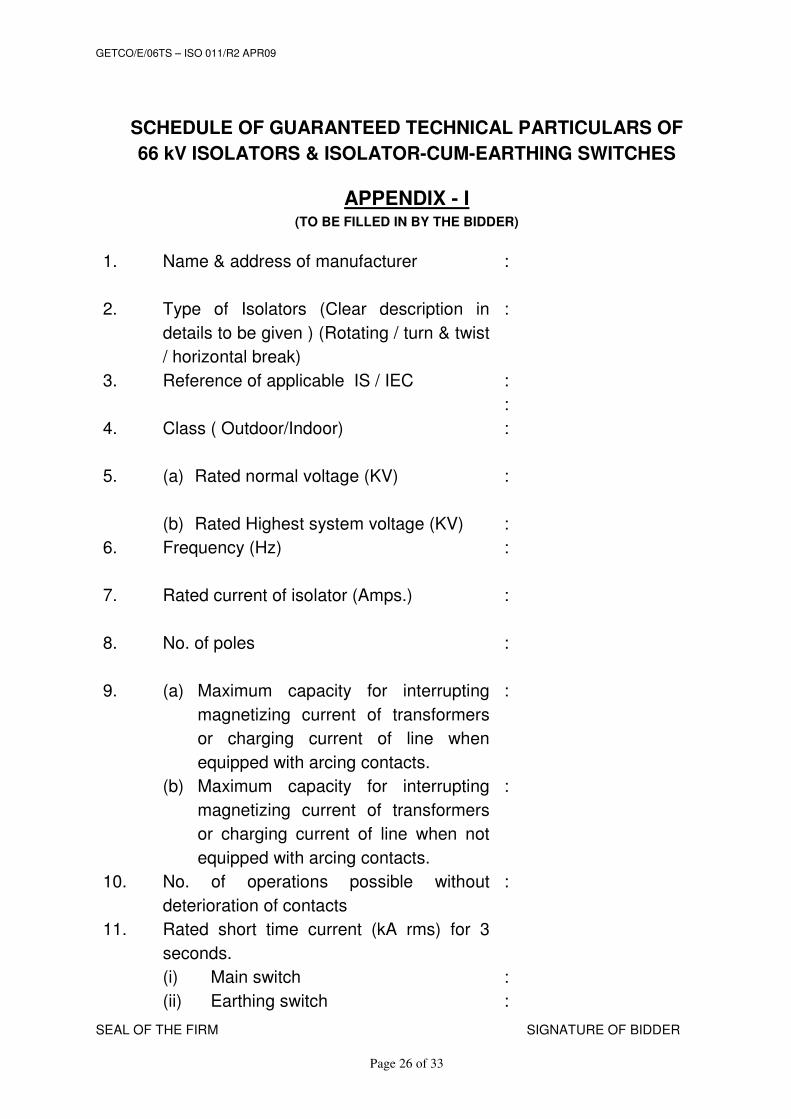
SCHEDULE OF GUARANTEED TECHNICAL PARTICULARS OF
66 kV ISOLATORS & ISOLATOR-CUM-EARTHING SWITCHES
APPENDIX - I (TO BE FILLED IN BY THE BIDDER)
1.
Name & address of manufacturer :
2.
Type of Isolators (Clear description in
details to be given ) (Rotating / turn & twist
/ horizontal break)
:
3.
Reference of applicable IS / IEC :
:
4.
Class ( Outdoor/Indoor) :
5.
(a) Rated normal voltage (KV)
(b) Rated Highest system voltage (KV)
:
:
6.
Frequency (Hz) :
7.
Rated current of isolator (Amps.) :
8.
No. of poles :
9.
(a) Maximum capacity for interrupting
magnetizing current of transformers
or charging current of line when
equipped with arcing contacts.
(b) Maximum capacity for interrupting
magnetizing current of transformers
or charging current of line when not
equipped with arcing contacts.
:
:
10.
No. of operations possible without
deterioration of contacts
:
11.
Rated short time current (kA rms) for 3
seconds.
(i) Main switch
(ii) Earthing switch
:
:

GETCO/E/06TS – ISO 011/R2 APR09
SEAL OF THE FIRM SIGNATURE OF BIDDER
Page 27 of 33
12.
Rated peak short circuit current (kAp) :
13.
Rated current of earthing switches (Amps) :
14.
Type of mounting :
15.
Phase – Centre - Phase clearance (mm) :
16.
Minimum phase to phase clearance (mm) :
17.
a) Minimum phase to ground clearance
(mm) (up to plinth level)
b) Minimum clearance from base channel
to ground (mm)
c) Between live parts when switch is
open
:
:
:
18.
No. of solid core post insulators :
19.
No. of breaks per phase :
20.
Type of interlock between isolating switch
and earth switch
:
21.
Total minimum Creepage distance
suitable for heavily polluted atmosphere
(mm):
:
22.
Arcing contacts :
a) Type
b) Material
c) Whether contacts silver plated (Yes /
No.)
d) Minimum Thickness of silver coating
(mm)
e) Current carrying capacity (Amps.)
:
:
:
:
:
:
23.
Main contacts (fixed and moving)
a) Type
(1) Moving contact
: For Main For Earth
Isolator Switch
:
:

GETCO/E/06TS – ISO 011/R2 APR09
SEAL OF THE FIRM SIGNATURE OF BIDDER
Page 28 of 33
(2) Fixed contact (reverse loop type)
b) Material & grade
c) Whether contacts silver plated (Yes /
No)
d) Minimum Thickness of silver coating
(micron)
e) Contact area in sq.mm.
f) Contact pressure in Kg./cm2
(1) Moving contact (Kg./cm2)
(2) Fixed contact (Kg./cm2)
g) Current carrying capacity (Amp.)
h) Size of material used :
(2) Moving contact
(2) Fixed contact
i) Cross Sectional area
(1) Moving contact (mm2)
(2) Fixed contact (mm2)
j) Current density (at rated current)
(1) Moving contact (A/ mm2)
(2) Fixed contact (A/mm2)
:
:
:
:
:
:
:
:
:
:
:
:
:
:
24.(a)
Terminal pad
(1) Material
(2) Size
(3) Current density
24.(b) Contact support (main and earth switch) (i) Material and size of channel/block
(ii) Material and size of plate
24.(c) Turn and twist mechanism (i) Material and size of clamp
(ii) Material and size of spring
(iii) whether springs are enclosed
25 (a) Maximum temperature of current
carrying parts when carrying rated
current continuously. (0C)
(b) Maximum ambient temperature for
which (a) is applicable. (0C)
26.
a) Location and Number of bearing per
each phase
b) Manufacturer's Bearing No & type
designation.
:

GETCO/E/06TS – ISO 011/R2 APR09
SEAL OF THE FIRM SIGNATURE OF BIDDER
Page 29 of 33
27.
Weight of one compete Isolator (kg.)
(i) with structure
(ii) without structure
:
OPERATING MECHANISM : Manual/Motor operated
28.
Whether separate operating mechanism
provided for operation of main blades and
earthing blades.
:
29.
Height of location of operating handle
above foundation (mm).
:
30.
Length of operating handle (mm) :
31.
i) Torque required for operation of isolator
(kgm)
ii) Time required for opening and closing of
main & earth switch
:
:
32.
Insulation Levels :
i) 1.2/50 microsecond dry impulse
withstand voltage (Positive and
negative polarity) (KV peak)
(a) Across the isolating distance
(b) To earth and between poles
:
:
:
33.
i) One minute power frequency
withstands voltage (dry) (KV rms.)
(a) Across the isolating distance
(b) To earth and between poles
ii) One minute power frequency
withstands voltage (wet) (KV rms.)
:
:
:
:
34. Visible corona discharge voltage (KV rms.) :
35.
Temp. rise of main contact at rated current
corresponding to ambient temperature of
50 (0C)
:
36.
Maximum temp. rise of main contact at
rated short time current for 3 second (0C)
:
37.
Rated mechanical terminal loads
(excluding wind loads (Kg.)
:
38. CONTROL CABINET

GETCO/E/06TS – ISO 011/R2 APR09
SEAL OF THE FIRM SIGNATURE OF BIDDER
Page 30 of 33
a) Material
b) Thickness
c) Size
d) Electrical ON/OFF indication
e) Type of motor
f) Rating of motor
g) Degree of protection
h) Material & thickness of gasket
i) Cable gland plate Material & thickness
DETAILS OF SOLID CORE POST
INSULATORS:
:
39.
Maker's type designation :
40. Applicable Standard and Drawing no. :
41. No. of units per stack
:
42.
i) Height of insulator
ii) Weight of each insulator
iii) Diameter of largest shed
iv) Total creepage distance, in mm
v) Nominal voltage
vi) Highest system voltage
:
:
:
:
:
:
43.
1 Minute power frequency withstand
voltage (Dry & wet) (KV rms.)
:
44.
1 Minute Power Frequency flash over
voltage (Dry and Wet) (KV rms)
:
45.
1.2/50 microsecond lightning impulse
withstand voltage (KV peak)
:
46.
Standard dry impulse flashover voltage
(KV peak)
:
47.
Minimum visible corona discharge voltage
(KV rms)
:

GETCO/E/06TS – ISO 011/R2 APR09
SEAL OF THE FIRM SIGNATURE OF BIDDER
Page 31 of 33
48.
Puncture voltage (KV rms) :
49.
i) Tensile strength (Kg).
ii) Compressive strength (Kg).
:
50.
i) Torsional strength (Kg).
ii) Cantilever strength (Kg).
:
51.
Galvanizing :
i) Applicable standard
ii) Method of Galvanizing.
iii) Weight of zinc coating (gm/cm2)
:
52. Top PCD
Bottom PCD
:
:
53. Provision of continuous adjustment /
alignment of insulators
:
54.
Loading details for design of foundation
i) For isolator
ii) For isolator-cum-earthing switches
:
:
55.
Weight, space requirement etc.
i) Weight of complete isolator with
operating mechanism, supports etc.
ii) Weight of complete isolator-cum-earthing switch with operating mechanism supports etc.
iii) Space required for Isolators ( L x W x H )
iv) Space required for Isolators-cum-
earthing switch ( L x W x H )
:
:
56. Details of earth blade
(a) Material
(b) Rated current
(c) Size (Diameter – mm)
57. BASE Material (Hot dip galvanized)

GETCO/E/06TS – ISO 011/R2 APR09
SEAL OF THE FIRM SIGNATURE OF BIDDER
Page 32 of 33
SIZE
WEIGHT
58. Insulating sleeve for operating handle
(a) Make
(b) Rating
(c) Type
59. Type of auxiliary contacts (i) For isolator (Normal) (Spare) (ii) For earth switch (Normal) (Spare) (iii) MBB contacts (Normal) (Spare)
:
:
:
:
:
60. No. of auxiliary contacts (i) For isolator (Normal) (Spare) (ii) For earth switch (Normal) (Spare) (iii) MBB contacts (Normal) (Spare)
:
:
:
:
:
61. Terminal connectors (a) Material of connector (b) Material of Nut/Bolts (c) Range of diameter of conductors
that can be received (d) Maximum temperature rise when
carrying rated current at 50 0C ambient temperature
(e) Weight of each type of connector (kg) (f) whether horizontal/vertical take-off (g) Flexible/rigid
:
:
:
:
:
:
:
62. RATING/NAME PLATE
a) Material
b) Thickness
c) Size
d) Depth of engraving letters
GETCO/E/06TS – ISO 011/R2 APR09
SEAL OF THE FIRM SIGNATURE OF BIDDER
Page 33 of 33
63. Type of Interlocks :
a) Constructional b) Mechanical c) Electrical
SEAL OF THE FIRM SIGNATURE OF BIDDER