gujarat electricity regulatory commission ( · pdf fileregulation) act, 2003 ... gujarat...
TRANSCRIPT
Page 1 Of 92
GUJARAT ELECTRICITY REGULATORY
COMMISSION (GERC)
Grid Code
Notification: No. 5 of 2004
In exercise of the powers conferred under Section 86(h) of the Electricity Act, 2003 (Act 36
of 2003) and under Section 42 (b) of the Gujarat Electricity Industry (Reorganisation and
Regulation) Act, 2003 (Gujarat Act 24 of 2003), and all powers enabling it in that behalf, the
Gujarat Electricity Regulatory Commission hereby makes this "GUJARAT ELECTRICITY
GRID CODE" herein after called Grid Code. This Grid Code is applicable for the Gujarat
Power Grid only and for the Inter State Transmission, Indian Electricity Grid Code shall be
applicable.
Page 2 Of 92
1. SECTION-1
INTRODUCTION
1.1 OVERVIEW:
1.1.1 The Gujarat Government, in exercise of powers under the Gujarat Electricity Industry
(Reorganisation and Regulation) Act, 2003, has notified the transfer scheme.
Accordingly, Gujarat Energy Transmission Corporation Limited (GETCO) will
continue to undertake Transmission activities and business as before on behalf of and
as an agent of the GEB till such time the state Government issues an order authorizing
the GETCO to undertake such functions and activities on their own and independent
of the GEB. As per the Section 39(2) of the Electricity Act
2003 following are the function of State Transmission Utility to:
(a) Undertake transmission of Energy through the Intra-state Transmission System
(b) Discharge all functions of planning and co-ordination relating to intra-state
transmission system with-
(i) Central Transmission Utility;
(ii) State Governments;
(iii) Generating Companies;
(iv) Regional Power Committee;
(v) Authority;
(vi) Licensees;
(vii) Any other person notified by the State Government in this behalf.
(c) Ensure development of an efficient, co-ordinated and economical system of
intra-State transmission lines for smooth flow of electricity from a generating
station to load centers;
(d) Provide non-discriminatory open access to its transmission system for use by-
(i) any licensee or generating company on payment of the transmission
charges;
or
(ii) any consumer as and when such open access is provided by the State
Commission under sub-section (2) of section 42, on payment of the
transmission charges and a surcharge thereon, as may be specified by the State
Commission
1.1.2 As per the Section 31 (2) of Electricity Act, 2003, the State Load Despatch Centre
shall be operated by a Government company/ any authority or corporation established
or constituted by or under any State Act, as may be notified by the state Government.
Until a Government company or any authority or corporation is notified by the State
Government, the State Transmission Utility shall operate the State Load Despatch

Page 3 Of 92
Centre. As per Section 32 (2) of Electricity Act, 2003, the following are the functions
of State Load Despatch Centre, which shall :
(a) be responsible for optimum scheduling and despach of electricity within a State,
in accordance with the contracts entered into with teh Licensees or the Generating
Companies operating in that State;
(b) monitor the grid operations;
(c) keep accounts of the quantity of electricity transmitted through the State grid;
(d) exercise supervision and control over the intra-state transmission system;
(e) be responsible for carrying out real time operations for grid control and despatch
of electricity within the State through secure and economic operation of the State
grid in accordance with the Grid Standards and the state Grid Code.
(f) Further, The SLDC and Licensees shall comply with; and ensure directions
Regional Load Despatch Centre may give from time to time in connection with
the integrated grid operation of the power system or otherwise in regard to matter
which affect the operation of the Inter State Transmission System.
1.1.3 In order to perform the above task as well as the requirements as stipulated in Clause
86(h) of the Electricity Act, 2003 and Clause 42 (b) of Gujarat Act No. 24 of 2003
viz. Gujarat Electricity Industry (Reorganisation and Regulation) Act 2003, the
Gujarat Electricity Regulatory Commission has formulated this "GUJARAT
ELECTRICITY GRID CODE" herein after called Grid Code. This Grid Code is
applicable for the Gujarat Power Grid only and for the Inter State Transmission,
Indian Electricity Grid Code shall be applicable.
1.1.4 Scope of Grid Code:
The Grid Code is designed to facilitate the development, operation and maintenance
of an efficient, co-ordinated and economical Gujarat power grid by specifying to
STU/ Transmission Licensees and all the Users connected to that system for their
technical and procedural obligations. It seeks to be non-discriminatory and to ensure
that interfaces are not areas of weakness in the supply chain.
1.2 STRUCTURE OF THE GRID CODE:
This Grid Code consists of 14 Sections as follows:
1.2.1 Section-1: Introduction – This section outlines the broad features of the Grid Code.
1.2.2 Section-2: Definitions - The various terms used in the Grid Code are defined under
this section.
1.2.3 Section-3: Management of Grid Code - The Grid Code is a live document and has
to be periodically reviewed by a competent panel as and when required in the light of
experience gained. This section formulates the procedures for the same.
1.2.4 Section-4: System Planning code – This section specifies the technical and design
criteria and the procedures to be applied by the State Transmission Utility and other
Users for planning and development of the power system.
1.2.5 Section-5: Connectivity Conditions – This section specifies the technical criteria and
standards to be complied with by STU, Transmission Licensees, the Generating

Page 4 Of 92
Companies, the Distribution Licensees and other Users connected or seeking
connection to the Transmission System.
1.2.6 Section-6: Operation Planning and Security – This section specifies the process by
which STU has to carry out the planning of intra state Transmission System, including
interface co-ordination with the Users, for a satisfactory grid operation and system
integrity.
1.2.7 Section-7: System Operation Metering, Protection, Despatch and Control Code –
This section specifies the procedure to be adopted for the scheduling of despatch of
the Generating Units to meet the demand and drawal allocations. This section also
covers the management of frequency and voltages in the Transmission System, the
minimum requirement of protection levels and metering specifications for the various
components of the system.
1.2.8 Section-8: Monitoring of Generation and drawal – This section formulates the
procedure to be followed by the State Load Despatch Centre for monitoring the
generation output, active and reactive reserve capacity required for evaluation of the
performance of Generating Stations. The monitoring of scheduled drawal is important
to ensure that SLDC contributes towards improving the Regional performance, by
observing Grid discipline.
1.2.9 Section-9: Contingency Planning – This section formulates the recovery and
normalisation of power supply process to be followed by all the Users in the event of
the failure of Gujarat power grid, or the Western Grid resulting in total or partial
collapse of the System causing blackouts.
1.2.10 Section-10: Cross Boundary Safety – This section specifies the requirements for
safe working practices for maintenance of equipment associated with cross boundary
operations and also the procedure to be followed when the work is carried out on
electrical equipment connected to another User's System.
1.2.11 Section-11: Safety and Line Clear Permits – This section sets out the procedure for
recording of Line Clear Permits and guidelines for ensuring safety from electrical
hazards to the consumers, general public and working personnel.
1.2.12 Section-12: Communication and Data acquisition – This section specifies the
minimum requirements of Communication and Data Acquisition Facilities to be
provided by each User at Connection Points/ Interface Points and cross boundary
circuits.
1.2.13 Section-13: Operational Event and Incident/Accident Reporting – This section
specifies the details of minimum requirement for the exchange of information relating
to Operations and/or Events on the total System including the Western Grid which
may have an operational effect.
1.2.14 Section-14: Data Registration – This section specifies a list of all the data required
by STU/ Transmission Licensee which is to be provided by the Users and the data
required by the Users to be provided by the STU/ Transmission Licensee at the
required time specified in the various sections of the Grid Code.

Page 5 Of 92
1.3 IMPLEMENTATION AND OPERATION OF THE GRID CODE:
1.3.1 The State Transmission Utility/ Transmission Licensee shall be responsible for
implementation of the Grid Code. All the Users shall comply with the Grid Code and
assist the State Transmission Utility/ Transmission Licensee in this regard. The Users
must provide all the required information and reasonable rights of access, service and
facilities necessary for implementation of the Grid Code.
1.3.2 If any User has any difficulty in complying with any of the provisions of the Grid
Code, he shall immediately, without delay, inform the same to the State Transmission
Utility as well as concerned Transmission Licensee, if any, and shall remedy his non-
compliance promptly.
1.3.3 Consistent failure in compliance with the Grid Code may lead to disconnection of the
User’s plant or Apparatus. The responsibility for the consequences of disconnection
including payment of damages and compensation to consumers rests with the User
who consistently violates the Grid Code.
1.3.4 The operation of the Grid Code shall be reviewed regularly by the Grid Code Review
Panel in accordance with the provisions of the relevant section of the Grid Code.
1.4 LIMITATIONS OF THE GRID CODE:
1.4.1 The Grid Code contains procedures for the management of day to day technical
situations in the Power Grid, taking into account a wide range of operational conditions likely
to be encountered under both normal and abnormal conditions. The Grid Code cannot foresee
all the possible operating conditions. Users must therefore understand and accept that the
SLDC/ STU/Transmission Licensee, in such unforeseen circumstances, may be required to
act decisively to discharge his obligations as well as to maintain the security of the System.
Users shall provide such reasonable co-operation and assistance as the STU/Transmission
Licensee may require in such circumstances. The STU/Transmission Licensee / SLDC shall
however refer all such cases for ratification in the next meeting of the Panel.
1.5 CONFIDENTIALITY
1.5.1 Under the terms of Grid Code, STU/ Transmission Licensee will receive information
from Users relating to their intentions in respect of their generation or supply
businesses. STU/ Transmission Licensee shall not, other than as required by Grid
Code, disclose such information to any other person without the prior written consent
of such informant, unless required by Central/State government departments or any
authority.
1.6 PROCEDURES TO SETTLE DISPUTES:
1.6.1 In the event of any dispute regarding interpretation between any User and STU, the
matter shall be referred to Gujarat Electricity Regulatory Commission. In the event of

Page 6 Of 92
any conflict between the parties regarding any provision of the Grid Code, the Gujarat
Electricity Regulatory Commission will proceed to settle the issue.
1.7 COMMUNICATIONS BETWEEN STU/ TRANSMISSION LICENSEE AND
USERS
1.7.1 All communications between STU/ Transmission Licensee and Users shall be in
accordance with the provision of the Grid Code. Unless otherwise specifically
required by the Grid Code, all communications shall be in writing, except where
operation time scales require oral communication, in which case these
communications shall be confirmed in writing as soon as practicable. All the Users
shall establish and maintain a reliable communication infrastructure and network for
this purpose.
1.8 DIRECTIVES
1.8.1 Under the provisions of the Act, the State Government may issue policy directives in
certain matters. The STU/ Transmission Licensee shall promptly inform GERC and
all Users of the requirement of such directives. The Users, subject to the relevant
section of the Acts, shall comply with such directive.
***

Page 7 Of 92
SECTION-2
DEFINITIONS
In the Grid Code the following words and expressions shall, unless the subject matter or
context otherwise requires or is inconsistent therewith, bear the following meanings:
Act The Electricity Act, 2003 and Gujarat Electricity Industry
(Reorganisation and Regulation) Act, 2003 read together.
Active Energy The electrical energy produced, flowing or supplied by an electric
circuit during a time interval, being the integral with respect to
time of the instantaneous power, measured in units of watt-hours
or standard multiples thereof, i.e.,
1000 Wh =1 kWh
1000 kWh = 1 MWh
1000 MWh = 1 GWh
1000 GWh = 1 TWh
Active Power The product of voltage and the in-phase component of alternating
current measured in units of watts and standard multiples thereof,
i.e.,
1000 Watts = 1 kW
1000 kW = 1 MW
1000 MW = 1 GW
1000 GW = 1 TW
AECo. The Ahmedabad Electricity Company Limited
Apparatus All the electrical apparatus like machines, fittings, accessories and
appliances in which electrical conductors are used.
Apparent Power The product of voltage and alternating current measured in units of
volt-amperes and standard multiples thereof, i.e.,
1000 VA = 1 kVA
1000 kVA = 1 MVA
Area Load
Despatch Centre
One of the three stations in Gujarat State being established under
Western Region System Unified Load Despatch Scheme, having
as main functions: - Data acquisition and transfer to SLDC; and
supervisory control of load centre in their respective area
Area of supply Area within which a Distribution Licensee is authorised by his
License to supply Electricity
Automatic Voltage
Regulator (AVR)
A continuously acting automatic excitation system to control a
Generating Unit terminal voltage.

Page 8 Of 92
Auxiliaries All the plant and machinery required for the Generating Unit's
functional operation that do not form part of the Generating Unit.
Availability "Fully Available" shall mean that the Generating Unit is available
to its contracted capacity. In respect of the Transmission System,
"Availability" shall mean the time in hours the Transmission
System is capable of transmitting electricity at its rated voltage
from the supply point to the delivery point and expressed as a
percentage of Annual Availability.
Backing Down Reduction of generation on instructions from SLDC/WRLDC by a
Generating Unit under abnormal conditions.
Black Start The procedure necessary for a recovery from a total shutdown or
partial shutdown without the availability of electricity from
external sources.
Black Start
Capability
An ability in respect of a Black Start Station, for at least one of its
Generating Units or CCGT Units to start-up from shutdown and to
energise a part of the system and be synchronised to the system
upon instruction from the State Load Dispatch Centre, within two
hours, without any external supply.
Black Start Stations Generating Stations having Black Start Capability.
Captive Power
Plant (CPP)
A Power Plant set up by any person to generate electricity for his
use and includes a power plant set up by any co-operative society
or association of persons for generating electricity primarily for
use of members of such co-operative society or association.
Caution Notice A notice conveying a warning against interference.
CBIP Central Board of Irrigation and Power.
CCGT Combined Cycle Gas Turbine.
CEA Central Electricity Authority.
Central
Transmission
Utility (CTU)
Any Government Company which the Central Government may
notify under sub section (1) of section 38 of the Electricity Act,
2003.
CERC Central Electricity Regulatory Commission.
Connection The electric power lines and electrical equipment used to effect a
connection of a User's System to the Transmission System.
Connection
Conditions
Those conditions mentioned in Section 5 (“Connection
Conditions”) which have to be fulfilled before the User’s System
is connected to the Grid.
Connection Point/
Interface Point
An electrical point of connection between the Transmission
System and the User's System.
Consumer Any person who is supplied with electricity for his own use by a

Page 9 Of 92
Licensee or the Government or by any other person engaged in the
business of supplying electricity to public under the Electricity Act
2003 or any other law for the time being in force and includes any
person whose Premises are for the time being connected for the
purpose of receiving electricity with the works of a Licensee, the
Government or such other person, as case may be.
Control Person A person identified as having technical capability and
responsibility for cross boundary safety under section 10 “Cross
Boundary Safety” of the Grid Code.
Demand The demand in MW and MVA of electricity (i.e. both Active and
Apparent Power), unless otherwise stated.
Demand Control Any of the following methods of achieving a Load reduction:
(a) Consumer Load Management initiated by Users.
(b) Consumer Load reduction by Disconnection initiated by Users
(other than following an instruction from Load Despatch
Centre).
(c) Consumer Load reduction instructed by the Load Despatch
Centre.
(d) Automatic under Frequency Load Disconnection.
(e) Emergency manual Load Disconnection.
Despatch Operational control of an integrated electricity system involving
operations such as:
(a) Assignment of levels of output to specific Generating Plant or
Load control devices to effect the most reliable and economical
supply as the loads vary,
(b) The control of the operation of Extra High Voltage lines,
associated substations and equipment,
(c) The scheduling of various types of transactions with the
electric utilities over the interconnecting Transmission Lines.
De-Synchronize The act of taking a Generating Unit off a system to which it has
been Synchronised.
Disconnection The physical separation of Users or Consumers from the System.
Discrimination The quality where a relay or protective system is enabled to pick
out and cause to be disconnected only the faulty Apparatus.
Distribution
Licensees
A Licensee authorised to operate and maintain a Distribution
System for supplying electricity to the Consumers in his Area of
Supply.
Distribution System The system of wires and associated facilities between the delivery
points on the transmission lines or the generating station
connection and the point of connection to the installation of the
Page 10 Of 92
Consumers.
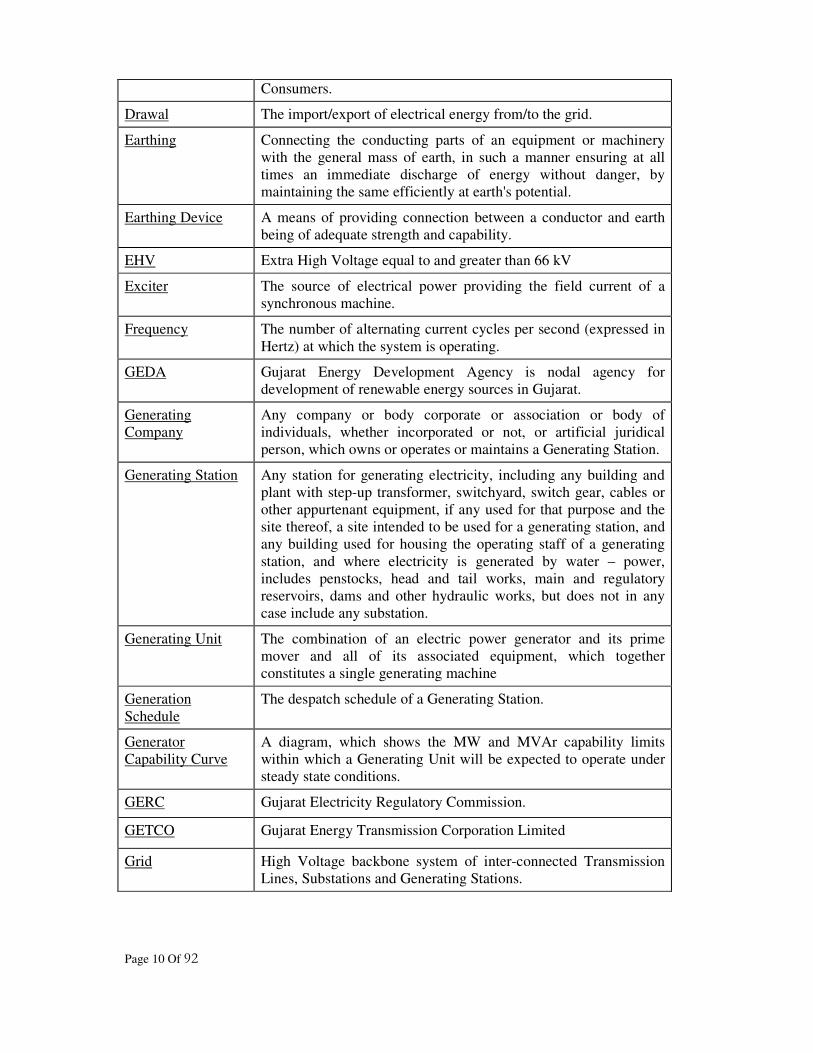
Drawal The import/export of electrical energy from/to the grid.
Earthing Connecting the conducting parts of an equipment or machinery
with the general mass of earth, in such a manner ensuring at all
times an immediate discharge of energy without danger, by
maintaining the same efficiently at earth's potential.
Earthing Device A means of providing connection between a conductor and earth
being of adequate strength and capability.
EHV Extra High Voltage equal to and greater than 66 kV
Exciter The source of electrical power providing the field current of a
synchronous machine.
Frequency The number of alternating current cycles per second (expressed in
Hertz) at which the system is operating.
GEDA Gujarat Energy Development Agency is nodal agency for
development of renewable energy sources in Gujarat.
Generating
Company
Any company or body corporate or association or body of
individuals, whether incorporated or not, or artificial juridical
person, which owns or operates or maintains a Generating Station.
Generating Station Any station for generating electricity, including any building and
plant with step-up transformer, switchyard, switch gear, cables or
other appurtenant equipment, if any used for that purpose and the
site thereof, a site intended to be used for a generating station, and
any building used for housing the operating staff of a generating
station, and where electricity is generated by water – power,
includes penstocks, head and tail works, main and regulatory
reservoirs, dams and other hydraulic works, but does not in any
case include any substation.
Generating Unit The combination of an electric power generator and its prime
mover and all of its associated equipment, which together
constitutes a single generating machine
Generation
Schedule
The despatch schedule of a Generating Station.
Generator
Capability Curve
A diagram, which shows the MW and MVAr capability limits
within which a Generating Unit will be expected to operate under
steady state conditions.
GERC Gujarat Electricity Regulatory Commission.
GETCO Gujarat Energy Transmission Corporation Limited
Grid High Voltage backbone system of inter-connected Transmission
Lines, Substations and Generating Stations.

Page 11 Of 92
Grid Code "Gujarat Electricity Grid Code" - a document describing the
procedures and the responsibilities for planning and operation of
Gujarat Grid.
Grid Code Review
Panel or "Panel"
The Panel with the functions set out in the Grid Code.
GSECL Gujarat State Electricity Corporation Limited
High Voltage or
HV
Voltage greater than 440 V and lesser than 66 kV.
IEC International Electro-Technical Commission
IEC Standard A standard approved by the International Electro-technical
Commission.
IEEE Institution of Electrical and Electronic Engineers, Inc., USA.
IEGC Indian Electricity Grid Code, a document developed by the Central
Transmission Utility and approved by the Central Electricity
Regulatory Commission.
Indian Standards
("IS")
Those Standards and specifications approved by the Bureau of
Indian Standards.
Inter-State
Generating Station
(ISGS)
A Generating Station in which two or more than two States have a
share and whose scheduling is to be coordinated by Regional Load
Despatch Centre.
Inter-State
Transmission
System (ISTS)
Inter-state Transmission System includes:
(a) Any system for the conveyance of electricity by means of a
main Transmission Line from the territory of one State to
another State;
(b) the conveyance of electricity across the territory of an
intervening State as well as conveyance within a State, which
is incidental to such inter-state transmission of electricity.
(c) The transmission of electricity within the territory of a State
built, owned, operated, maintained or controlled by the Central
Transmission Utility.
Interconnecting
Transformer (ICT)
Transformer connecting EHV lines of different voltage systems.
Intertripping (a) The tripping of circuit-breaker(s) by commands initiated from
Protection at a remote location independent of the state of local
Protection; or
(b) Operational intertripping.
Intra-state
Transmission
System
Any system for transmission of electricity other than an Inter-
State Transmission System.

Page 12 Of 92
Isolation The disconnection of EHV/ HV Apparatus from the remainder of
the System in which that EHV/ HV Apparatus is situated.
Lean Period That period in a day when the electrical power demand is lowest.
Licence Any license granted by GERC under provisions of the relevant
laws in force.
Load The Active, Reactive or Apparent Power as the context requires,
generated, transmitted or distributed.
Load Factor Load Factor is the ratio of the average power to the maximum
demand. The load factor depends on the interval of time of the
maximum demand and the period over which the average is taken.
Units consumed in a given period
Load Factor = -------------------------------------------------------
Maximum Demand x No. of hours in the period
Low Voltage or LV Voltage not exceeding 440 volts.
Main Protection Protection equipment or system expected to have priority in
initiating either a fault clearance or an action to terminate an
abnormal condition in a power system.
Notice to
Synchronise
The amount of time (expressed in minutes) that is declared by a
Generating Company in relation to a Generator to enable it to be
synchronised following the receipt of an instruction to
synchronise.
NPC Nuclear Power Corporation Limited
NTPC National Thermal Power Corporation Limited
Operating Margin Aggregate available capacity of Generating Station in the system
on real time basis, which is over and above the operating level to
the maximum capacity of the Generating Units limited by
technical parameters for short duration.
Operation A scheduled or planned action relating to the operation of a
System.
Operational
Procedures
Management instructions and procedures, both for the Safety
Rules and for the local and remote operation of plant and
Apparatus, issued in connection with the actual operation of plant
and/or Apparatus at or from a connecting site.
Out of Synchronism The condition where a System or Generating Unit can not meet the
requirements to enable it to be Synchronised.
Outage A total or partial regulation in availability due to repair and
maintenance of the Transmission or Distribution or Generation
facility or defect in Auxiliary System.
Part Load The condition of a Generating Station which is loaded but is not
running at its declared availability.

Page 13 Of 92
Partial Shutdown A shutdown of a part of the system resulting in failure of power
supply, either from external connections or from the healthy part
of the system.
Peak Period That period in a day when the electrical power Demand is highest.
Person Any company or body corporate or association or body of
individuals, whether incorporated or not, or artificial juridical
person.
PGCIL Power Grid Corporation of India Limited.
Planned Outage An outage of Generating Plant or part of the Transmission System,
or part of a User's system co-ordinated by SLDC.
Power Factor The ratio of Active Power (kW) to Apparent Power (KVA).
Premises Any land, building or structure
Protection The schemes and Apparatus for detecting abnormal conditions on
a System and initiating fault clearance or actuating signals or
indications.
Protection
Apparatus
A group of one or more Protection Relays and/or logic elements
designated to perform a specified Protection function.
Rated MW The "rating plate" MW output of a Generating Unit, being that
output up to which the Generating Unit is designed to operate.
Reactive Power The product of voltage and current and the sine of the phase angle
between them measured in units of volt-amperes reactive and
standard multiples thereof, i.e.:
1000 VAr. = 1kVAr
1000 kVAr = 1 MVAr
Regional Power
Committee
Committee established by resolution by the Central Government
for a specified region for facilitating the integrated operation of the
power system in the region.
Regulating Margin The system voltage and frequency beyond which the system
should not be operated.
Responsible
Engineer/ Operator
A person nominated by an User to be responsible for System
control.
Re-synchronization The bringing of parts of the System which has gone out of
Synchronism with each other, back into Synchronism.
Safety Rules The rules framed by the Users and the Transmission Licensee to
ensure safety to persons working on Plant/Apparatus.
SECo The Surat Electricity Company Limited
SLDC State Load Despatch Centre.

Page 14 Of 92
Standing
Instructions
An instruction issued by SLDC to a Generating Company
whereby, in specified circumstances, the Generating Company
should take specified action, as though a valid dispatch instruction
has been issued by SLDC.
Start-Up The action of bringing a Generating Unit from shutdown to
synchronous speed.
State Transmission
Utility (STU)
The utility notified by the Government under Sub-Section (1) of
Section 39 of the Electricity Act, 2003, and whose functions have
been outlined under Sub-Section (2) of Section 39 of the
Electricity Act, 2003.
Station Transformer A transformer supplying electrical power to the Auxiliaries of a
Generating Station, which is not directly connected to a
Generating Unit terminal.
Substation Station for transforming or converting electricity for the
transmission or distribution thereof and includes transformers,
converters, switchgears, capacitors, synchronous condensers,
structures, cable and other appurtenant equipment and any
buildings used for that purpose and the site therof
Supervisory Control
and Data
Acquisition or
(SCADA)
The communication links and data processing systems, which
provide information to enable implementation of requisite
supervisory and control actions.
Synchronized Those conditions where an incoming Generating Unit or System is
connected to the busbars of another System so that the frequencies
and phase relationships of that Generating Unit or System as the
case may be, and the System to which it is connected are identical.
System Any Transmission and Distribution System and/or Transmission
System, as the case may be.
Total System The Transmission System and all User Systems in Gujarat.
Transmission
Licensee
A Licensee authorised to establish and operate transmission lines.
Transmission Line All high pressure cables and overhead lines (not being an essential
part of the distribution system of a Licensee) transmitting
electricity from a Generating Station to another Generating Station
or a Substation, together with any step-up and step-down
transformers, switch-gear and other works necessary to and used
for the control of such cables or overhead lines, and such buildings
or part thereof as may be required to accommodate such
transformers, switch-gear and other works
Transmission
System
The system consisting of high pressure cables and overhead lines
of Transmission Licensee for transmission of electrical power
from the Generating Station upto Connection Point/ Interface Point

Page 15 Of 92
with the Distribution System. This shall not include any part of the
Distribution System.
Under Frequency
Relay
An electrical measuring relay intended to operate when its
characteristic quantity reaches the relay settings by decrease in
frequency.
User A term utilised in various sections of Grid Code to refer to the
persons using the Gujarat Grid, as more particularly identified in
each section of the Grid Code. In the General Conditions the term
means any person to whom the Grid Code applies.
WRLDC Western Regional Load Despatch Centre.
Words and expressions used and not defined in this Code but defined in the Acts shall have
the meanings assigned to them in the said Acts. Expressions used herein but not specifically
defined in this Code or in the said Acts but defined under any law passed by a competent
legislature and applicable to the electricity industry in the state shall have the meaning
assigned to them in such law. Subject to the above, expressions used herein but not
specifically defined in this Code or in the Acts or any law passed by a competent legislature
shall have the meaning as is generally assigned in the electricity industry.
Interpretation
In the interpretation of this Code, unless the context otherwise requires:
• words in the singular or plural term, as the case may be, shall also be deemed to
include the plural or the singular term, respectively;
• the terms "include" or "including" shall be deemed to be followed by "without
limitation" or "but not limited to" regardless of whether such terms are followed by
such phrases or words of like import;
• references herein to the “code" shall be construed as a reference to this code as
amended or modified by the GERC from time to time in accordance with the
applicable laws in force.
• the headings are inserted for convenience and may not be taken into account for the
purpose of interpretation of this Code.
• references to any statutes, regulations or guidelines shall be construed as including all
statutory provisions consolidating, amending or replacing such statutes, regulations or
guidelines, as the case may be, referred to.
***

Page 16 Of 92
SECTION-3
MANAGEMENT OF GRID CODE
3.1 INTRODUCTION:
3.1.1 The STU/ Transmission Licensee is required to implement and comply with the
Gujarat Electricity Grid Code (GEGC) and to carry out periodic review and
amendments of the same with the approval of Gujarat Electricity Regulatory
Commission (GERC). A Review Panel shall be constituted by STU, as required in
this section, comprising of the representatives of the Users of the Transmission
System.
3.1.2 No change in this Grid Code, however small or big, shall be made without being
deliberated upon and agreed to by the Grid Code Review Panel and thereafter
approved by GERC. However, in an unusual situation where normal day to day
operation is not possible without revision of some clauses of Grid Code, a provisional
revision may be implemented before approval of GERC is received, but only after
discussion at a special Review Panel Meeting convened on emergency basis. GERC
should promptly be intimated about the provisional revision. GERC may issue
directions requiring STU to revise the Grid Code accordingly as may be specified in
those directions and STU shall promptly comply with any such directions.
3.1.3 STU/ Transmission Licensee will be responsible for managing and implementing the
Grid Code for discharging its obligations with the Users. STU/ Transmission Licensee
will not be, however, required to incur any expenditure on account of travel etc., of
any other member of the panel other than its own representative.
3.2 OBJECTIVE:
The objective of this section is to define the method of management of Grid Code
documents, implementing any changes/modifications required and the responsibilities
of the constituents (Users) to effect the change.
3.3 GRID CODE REVIEW PANEL:
3.3.1 The Chairperson of the Grid Code Review Panel shall be an Engineer of the STU not
below the rank of Chief Engineer. The Member Secretary of the Panel shall also be
nominated by STU. The Review Panel shall consist of the following members on the
recommendations of the heads of the respective organisations:
(a) One Chief Engineer or General Manager of Gujarat State Electricity Corporation
Limited (GSECL).
(b) One representative at senior executive level of The Ahmedabad Electricity
Company Limited (AECo).
(c) One representative at senior executive level of The Surat Electricity Company
Limited (SECo).
Page 17 Of 92
(d) One representative at senior executive level from National Thermal Power
Corporation Limited (NTPC).
(e) One representative at senior executive level from Western Regional Load
Despatch Centre (WRLDC).
(f) One representative at senior executive level from Regional Power Committee.
However, this member will be inducted after such committee comes into
existence.
(g) One representative at senior executive level from each Distribution Licensee other
than AECo and SECo.
(h) One representative at senior executive level from each of the Generating
Companies other than GSECL feeding the Gujarat Grid feeding not less than 50
MW.
(i) One representative from all CPPs, which are in parallel operation with Gujarat
Grid, on rotation basis.
(j) One representative from all the Generating Companies of small Generating
Stations of less than 50 MW capacity on rotation basis.
(k) One member from Gujarat Energy Development Agency (GEDA)
3.3.2 Any other member can be co-opted as a member of the panel when directed by
GERC.
3.3.3 The functioning of the panel shall be co-ordinated by STU. The Member Secretary
nominated by STU shall be the convenor.
3.3.4 STU shall inform all the Users, the names and addresses of the Review Panel
Chairperson and the Member Secretary at least 7 days before the first Review Panel
meeting. Any subsequent changes shall also be informed to all the Users by STU.
Similarly, each User shall inform the names and designations of their representatives
to the Member Secretary of the Review Panel, at least three days before the first
Review Panel meeting, and shall also inform the Member Secretary in writing
regarding any subsequent changes.
3.4 FUNCTIONS OF THE REVIEW PANEL:
The functions of the Review Panel are as follows:
(a) Maintenance of the Grid Code and its working under continuous scrutiny and
review.
(b) Consideration of all requests for review made by any User and publication of their
recommendations for changes in the Grid Code together with reasons for such
changes.
(c) Provide guidance on interpretation and implementation of the Grid Code.
(d) Examination of the problems raised by any User as well as resolution of the
problems.

Page 18 Of 92
(e) Ensuring that the changes/modifications proposed in the Grid Code are consistent
and compatible with Indian Electricity Grid Code (IEGC).
(f) Analysis of major Gujarat Grid disturbances soon after their occurrence and
constitute the sub committee to investigate the reasons thereof.
The Review Panel may hold any number of meetings as required subject to the
condition that at least one meeting shall be held in every three months. Sub-meetings
may be held by STU with the User to discuss individual requirements and with groups
of Users to prepare proposals for Review Panel’s consideration.
3.5 REVIEW AND REVISIONS:
3.5.1 The Users seeking any amendment to the Grid Code shall send written requests to the
Member Secretary of the Review Panel with a copy to GERC. If the request is sent to
GERC directly, the same shall be forwarded to STU who shall, in consultation with
the Distribution Licensees, Generating Companies, Central Transmission Utility
(CTU) and such other persons as the GERC may direct or STU may decide to consult,
review the Grid Code provisions. STU shall examine the proposed
changes/modifications in line with IEGC stipulations and circulate the same along
with its comments to all the Review Panel members for their written comments within
a reasonable time frame. Whenever it is observed that a certain clause of Grid Code is
not consistent with the IEGC, then the same will be discussed in the Review Panel
and the clause will be revised to make it consistent with IEGC.
3.5.2 All the comments received shall be scrutinised and compiled by STU. These along
with STU’s comments shall be sent to all the members for their response for the
proposed change/modification. If necessary, STU shall convene a meeting of the
Review Panel for deliberations. The Member Secretary shall present all the proposed
revisions of the Grid Code to the Review Panel for its consideration.
3.5.3 Based on the response received, STU shall finalise its recommendation regarding the
proposed modification / amendment and submit the same along with all the related
correspondence to GERC for approval.
3.5.4 STU shall send the following reports to the GERC at the conclusion of each review
meeting of the panel:
(a) Reports on the outcome of such review.
(b) Any proposed revision to the Grid Code as STU reasonably thinks necessary for
achievement of the objectives referred to in the relevant paragraphs of the
Transmission Licence.
(c) All written representations and objections submitted by the Users at the time of
review.
3.5.5 All revisions to the Grid Code require the approval of GERC. STU shall publish
revisions to the Grid Code, after the approval of GERC. STU may submit proposals
for relaxation in such cases where Users have difficulties in meeting the requirements
of the Grid Code.

Page 19 Of 92
3.5.6 Any change from the previous version shall be clearly marked in the margin. In
addition, a revision sheet shall be placed at the front of the revised version noting the
number of every changed sub-section, together with reasons for such change.
3.5.7 STU shall maintain copies of the Grid Code with the latest amendments and shall
make it available at a reasonable cost to any person requiring it. This may also be
made available on the website as soon as feasible. The STU/ Transmission Licensee
shall keep an up to date list of recipients of all the copies of the Grid Code, if found
necessary to ensure that the latest version of Grid Code is reached to all the relevant
recipients.
3.5.8 The Commission, may, on the application of the users or otherwise, call the
emergency meeting of the review panel as and when the situation so dictates and
make such alterations and amendments in the Grid Code as it thinks fit.
***

Page 20 Of 92
SECTION-4
SYSTEM PLANNING CODE
4.1.1 INTRODUCTION:
The System Planning specifies the technical and design criteria and procedures to be
adopted by STUfor the planning and development of the Transmission System. The
Users of the Transmission System shall take the "System planning" into account for
planning and development of their own System.
4.1.1 Reinforcements and extensions to the System arise due to many reasons of which a
few are mentioned below:
(a) A development on a User's System already connected to the Transmission System
as a User development.
(b) Introduction of a new Connection Point/ Interface Point between an User's System
and the Transmission System.
(c) The need to increase System capacity, removal of operational constraints,
maintenance of Security Standards and meeting general increases in Demand.
(d) Steady state and transient stability considerations.
(e) Cumulative effects of any combination of the above four.
4.1.2 The work of such reinforcement and extension to the Transmission System may also
involve work at a Connection Point / Interface Point of a Generating
Company/Distribution Licensee to the Transmission System.
4.1.3 The development of the Transmission System must be planned in advance duly
allowing sufficient lead time, considering the following:
(a) Time required for detailed engineering, design and construction work to be carried
out. This "System Planning", therefore, enforces the time scales for exchange of
information between the STU and the User(s). All the concerned parties, wherever
appropriate, shall have due regard to the confidentiality of such information;
(b) Time required for obtaining all the necessary statutory approvals like Notification
in government gazette and leading newspapers, Power and Telecommunication
Co-ordination Committee (PTCC) clearance, Forest clearance, Railway clearance,
Clearance from aviation authorities, National highways, State highways etc., and
the right of way permissions wherever required.
4.2 OBJECTIVE:
This section formulates the standards and procedures for the "System Planning" to
enable STU in consultation with the Users, to evolve an efficient, co-ordinated, secure
and economical Intra State Transmission System in order to satisfy the requirements
of Demand and Generation.

Page 21 Of 92
4.3 PERSPECTIVE PLAN:
4.3.1 The load forecasting shall be the primary responsibility of Distribution Licensee
within his Area of Supply. The Distribution Licensees shall determine the peak load
and energy forecasts of their areas for each of the succeeding 10 years and submit the
same annually by 31st January to STU. These shall include the details of demand
forecasts, data methodology and assumptions on which the forecasts are based. The
peak load and energy forecasts shall be made for overall Area of Supply. The annual
peak load forecast shall also be made for each Connection Point / Interface Point with
the Transmission System. The peak load requirement at each Connection Point /
Interface Point will essentially ensure that the STU may determine the corrective
measures to be taken to maintain the capacity adequacy in the Transmission System
upto the Connection Point /Interface Point. This will facilitate the Transmission
Licensee to develop the compatible Transmission System. However, if the
Distribution Licensee receives power at a number of Connection Points / Interface
Points in a compact area, which are interconnected in a ring, then such Distribution
Licensee shall forward the overall long term Demand forecast for Overall Area of
Supply as well as at each Connection Point / Interface Point with the variation or
tolerance as mutually discussed and agreed upon with the STU. These forecasts shall
be updated annually and also whenever major changes are made in the existing
system. Wherever these forecasts take into consideration demands for power
exceeding 5 MW by a single Consumer, the Distribution Licensee shall personally
satisfy himself regarding the materialisation of such a Demand.
4.3.2 STU shall also review the methodology and assumptions used by the Distribution
Licensees in making the Load forecasts, in consultation with them. The resulting
overall forecast will form the basis of planning for expansion of Transmission
System, which will be carried out by STU. To maintain the reliability of the
interconnected regional power systems, all participants must comply with the
planning criteria/guidelines of CEA as updated from time to time.
4.3.3 STU shall forecast the demand for power within the Area of Supply for each of the
succeeding ten years and provide to the GERC the details of demand forecasts, data,
methodology and assumptions on which the forecasts are based. Based on these
forecasts and in coordination with the various agencies identified under section 39 (2)
b of Electricity Act 2003, STU shall be responsible to prepare and submit a long term
(ten years) plan to the GERC for the compatible intra-state Transmission System
expansion to meet the future demand. The planning shall be in conformity with the
national perspective for Power Generation and Transmission plan prepared by the
CEA. This compatible intra-state Transmission Plan shall also include provision for
reactive compensation needed for the Transmission System.
4.3.4 STU shall be responsible for integrating the Load forecasts submitted by each of the
Distribution Licensees and determining the long-term (10 years) load forecasts for the
State. For determining the requirements for the entire State, an appropriate diversity
factor from the data available for the previous years shall have to be chosen. STU
shall satisfy itself regarding the probability of materialisation of bulk loads of
Consumers with Demands above 5 MW in consultation with the Distribution
Licensees concerned.

Page 22 Of 92
4.3.5 STU shall extend full support to CTU to finalise the annual planning corresponding to
a 5 year forward term for identification of major inter-state Transmission System
including inter-regional schemes which shall fit in with the long term plan developed
by CEA.
4.3.6 STU shall furnish the requisite planning data to CTU by 31st March every year to
enable CTU to formulate and finalise the plan by 30th
September each year for next
five years.
4.4 PLANNING STANDARDS AND PROCEDURES:
4.4.1 The Intra-State Transmission System shall be planned in accordance with the "
Transmission System Planning and Security Standard” (Attachment with this code).
4.5 PLANNING DATA REQUIREMENT:
4.5.1 To enable STU to discharge its responsibilities under the Transmission Licence by
conducting system studies and preparation of the perspective plans, all the Users shall
furnish all the data to STU from time to time detailed under Data Registration Section
and categorised as Planning Data (PD), vide Annexure "A". The data pertaining to the
Generating Stations including CPPs and Generating Units owned by Distribution
Licensee working in parallel with grid and Distribution Licensees shall be updated
upon any addition of Generating Unit/ modification of the Distribution System.
4.5.2 To enable the Users to co-ordinate planning, design and operation of their plants and
systems with the Transmission System they may seek certain salient data of the
Transmission System as applicable to them. STU/ Transmission Licensee shall supply
these data from time to time as detailed under Data Registration Section and
categorised as Detailed Transmission System Data vide Annexure "B".
4.5.3 In addition to the above provisions, the planning code of Indian Electricity Grid Code
(IEGC) which call for data exchange shall also apply to the Generating Companies,
CPPs, IPPs, Transmission Licensee, Utilities and Distribution Licensees regarding
generation / transmission of energy from Inter State Transmission Systems.
4.5.4 The one time data shall be submitted within 6 months from the date the Grid Code
comes into effect, by all the concerned to STU. The data other than this one time data
shall be made available to STU on first of April and first of October every year.
Page 23 Of 92
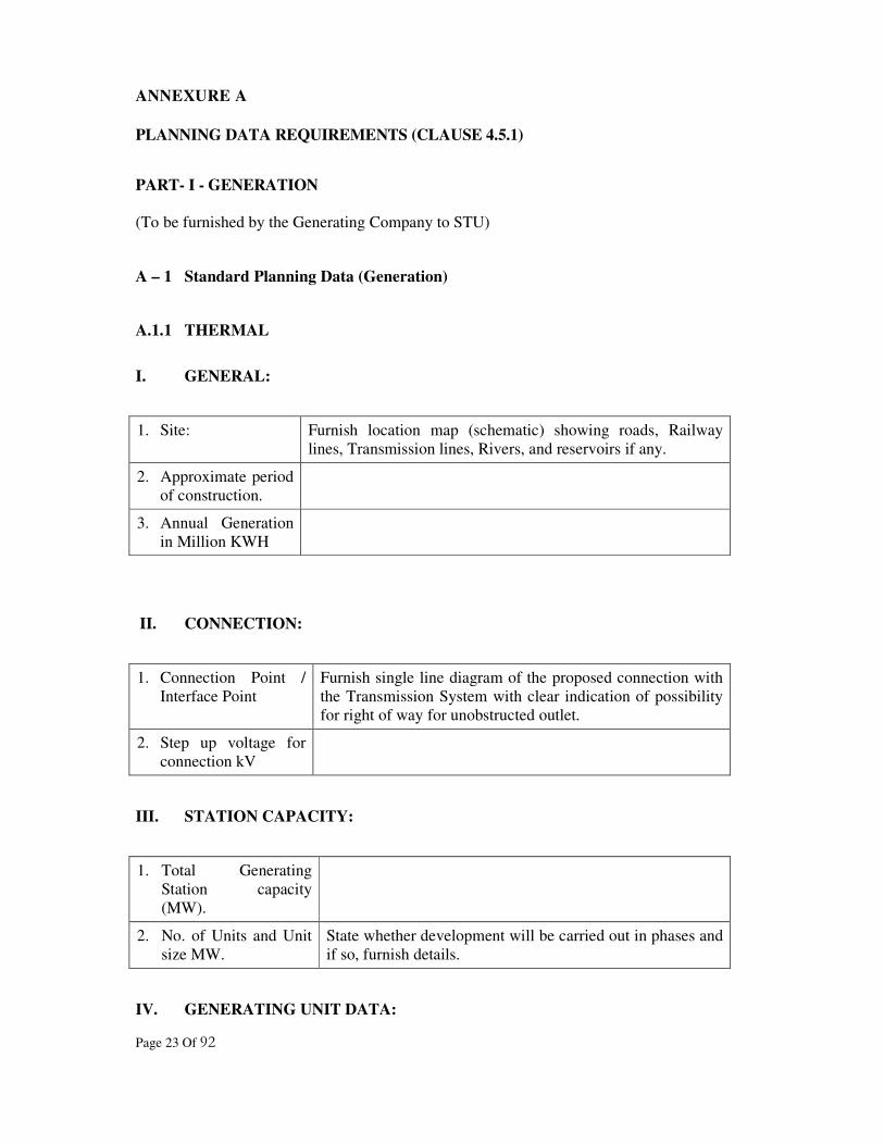
ANNEXURE A
PLANNING DATA REQUIREMENTS (CLAUSE 4.5.1)
PART- I - GENERATION
(To be furnished by the Generating Company to STU)
A – 1 Standard Planning Data (Generation)
A.1.1 THERMAL
I. GENERAL:
1. Site: Furnish location map (schematic) showing roads, Railway
lines, Transmission lines, Rivers, and reservoirs if any.
2. Approximate period
of construction.
3. Annual Generation
in Million KWH
II. CONNECTION:
1. Connection Point /
Interface Point
Furnish single line diagram of the proposed connection with
the Transmission System with clear indication of possibility
for right of way for unobstructed outlet.
2. Step up voltage for
connection kV
III. STATION CAPACITY:
1. Total Generating
Station capacity
(MW).
2. No. of Units and Unit
size MW.
State whether development will be carried out in phases and
if so, furnish details.
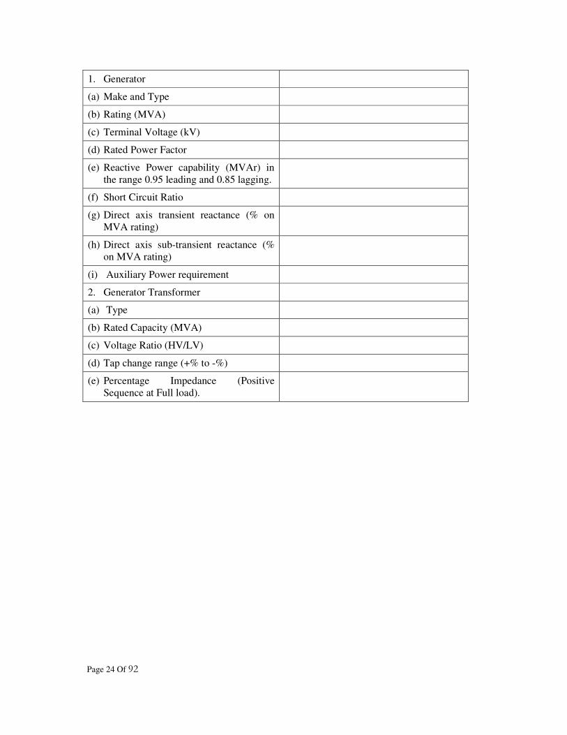
IV. GENERATING UNIT DATA:
Page 24 Of 92
1. Generator
(a) Make and Type
(b) Rating (MVA)
(c) Terminal Voltage (kV)
(d) Rated Power Factor
(e) Reactive Power capability (MVAr) in
the range 0.95 leading and 0.85 lagging.
(f) Short Circuit Ratio
(g) Direct axis transient reactance (% on
MVA rating)
(h) Direct axis sub-transient reactance (%
on MVA rating)
(i) Auxiliary Power requirement
2. Generator Transformer
(a) Type
(b) Rated Capacity (MVA)
(c) Voltage Ratio (HV/LV)
(d) Tap change range (+% to -%)
(e) Percentage Impedance (Positive
Sequence at Full load).

Page 25 Of 92
A.1.2 HYDRO ELECTRIC:
1. GENERAL:
(AS APPLICABLE TO THERMAL GENERATING STATIONS MENTIONED ABOVE)
II. CONNECTION:
(AS APPLICABLE TO THERMAL GENERATING STATIONS MENTIONED ABOVE)
III. STATION CAPACITY:
(AS APPLICABLE TO THERMAL GENERATING STATIONS MENTIONED ABOVE)
IV. GENERATION UNIT DATA:
(AS APPLICABLE TO THERMAL GENERATING STATIONS MENTIONED ABOVE)
Page 26 Of 92
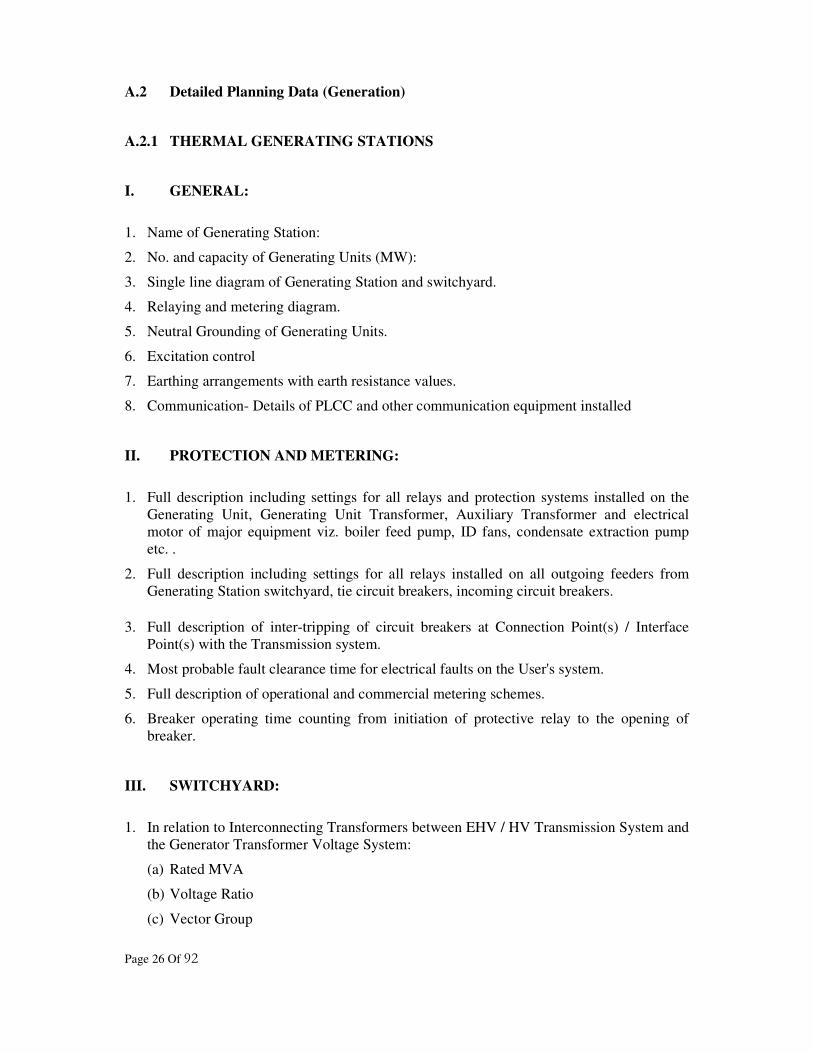
A.2 Detailed Planning Data (Generation)
A.2.1 THERMAL GENERATING STATIONS
I. GENERAL:
1. Name of Generating Station:
2. No. and capacity of Generating Units (MW):
3. Single line diagram of Generating Station and switchyard.
4. Relaying and metering diagram.
5. Neutral Grounding of Generating Units.
6. Excitation control
7. Earthing arrangements with earth resistance values.
8. Communication- Details of PLCC and other communication equipment installed
II. PROTECTION AND METERING:
1. Full description including settings for all relays and protection systems installed on the
Generating Unit, Generating Unit Transformer, Auxiliary Transformer and electrical
motor of major equipment viz. boiler feed pump, ID fans, condensate extraction pump
etc. .
2. Full description including settings for all relays installed on all outgoing feeders from
Generating Station switchyard, tie circuit breakers, incoming circuit breakers.
3. Full description of inter-tripping of circuit breakers at Connection Point(s) / Interface
Point(s) with the Transmission system.
4. Most probable fault clearance time for electrical faults on the User's system.
5. Full description of operational and commercial metering schemes.
6. Breaker operating time counting from initiation of protective relay to the opening of
breaker.
III. SWITCHYARD:
1. In relation to Interconnecting Transformers between EHV / HV Transmission System and
the Generator Transformer Voltage System:
(a) Rated MVA
(b) Voltage Ratio
(c) Vector Group

Page 27 Of 92
(d) Positive sequence reactance (maximum, minimum, normal Tap(% on MVA)
(e) Positive sequence resistance (maximum, minimum, normal Tap (% on MVA)
(f) Zero sequence reactance (% on MVA)
(g) Tap changer range (+ % to - %) and steps
(h) Type of tap changer (OFF/ON)
(i) Details of reactors, and other circuits connected to tertiary winding of ICT.
(j) Method of grounding.
2. In relation to switchgear including circuit breakers, isolators on all circuits connected to
the points of connection:
(a) Rated Voltage (kV)
(b) Type of Breaker (MOCB/ABCB/SF6 ---)
(c) Rated short circuit breaking current (kA) 3 Phase
(d) Rated short circuit breaking current (kA) 1 Phase
(e) Rated short circuit making current (kA) 3 Phase
(f) Rated short circuit making current (kA) 1 Phase
(g) Provisions of auto reclosing with details.
(h) Details of instrument transformers
3. Lightning arresters, technical data.
4. Communication- Details of PLCC and other communication equipment installed at
Connection Point(s)/ Interface Point(s).
5. Basic insulation level (kV).
(a) Bus bar.
(b) Switchgear.
(c) Transformer bushings.
(d) Transformer windings.
IV GENERATING UNITS:
A. PARAMETERS OF GENERATING UNITS:
1. Rated terminal voltage (kV)
2. Rated MVA
3. Rated MW
4. Inertia constant H (MW Sec./MVA) of Generator
5. Short circuit ratio
6. Direct axis synchronous reactance (% on MVA) (Both unsaturated and saturated)
7. Direct axis transient reactance (% on MVA) (Both unsaturated and saturated)

Page 28 Of 92
8. Direct axis sub-transient reactance (% on MVA) (Both unsaturated and saturated)
9. Quadrature axis synchronous reactance (% on MVA) (Both unsaturated and saturated)
10. Quadrature axis transient reactance (% on MVA) (Both unsaturated and saturated)
11. Quadrature axis sub-transient reactance (% on MVA) (Both unsaturated and saturated)
12. Direct axis transient open circuit time constant (Sec) T’ do
13. Direct axis sub-transient open circuit time constant (Sec) T”do
14. Quadrature axis transient open circuit time constant (Sec) T’qo
15. Quadrature axis sub-transient open circuit time constant (Sec) T”qo
16. Stator resistance (Ohm)
17. Stator leakage reactance (Ohm) Ta
18. Stator time constant (Sec)
19. Rated field current (A)
20. Open circuit saturation characteristic for various terminal voltages giving the exciting
current to achieve the same.
21. Generator Capability Curve
22. Rated stator current (A)
23. Phase connection
24. Number of terminals brought out
25. Rated speed (rpm)
26. Rated Frequency (Hz.)
27. Efficiency at MCR condition (percent)
28. Negative sequence current capability (I2T)
29. Capacitance of generator stator winding to ground (microF/ph)
30. DC resistance of rotor at 200 C (in ohm)
31. Zero sequence reactance X0 (Percentage)
32. Negative sequence reactance X2 (Percentage)
33. Negative sequence reactance R2 (Percentage)
34. Sub-Transient S-C time constant (in second)
(i) Direct axis T”d
(ii) Quadrature axis T”q
35. Transient S-C time constant (in second)
(i) Direct axis T’d
(ii) Quadrature axis T’q
36. Machine saturation at 1.0 pu voltage in p.u.
37. Machine saturation at 1.2 pu voltage in pu

Page 29 Of 92
38. Percentage regulation
39. Short circuit characteristics curves
B. PARAMETERS OF EXCITATION CONTROL SYSTEM:
1. Type of Excitation
2. Maximum Field voltage
3. Minimum Field voltage
4. Rated Field voltage
5. Gain factor
6. Feed back strength
7. Time constant for control amplifier
8. Time constant for Exciter
9. Time constant for Feed Back
10. Output voltage of control amplifier
11. Maximum output voltage of control amplifier
12. Minimum output voltage of control amplifier
13. Details of excitation loop in block diagrams showing transfer functions of individual
elements using IEEE symbols along with set values.
14. Dynamic characteristics of over - excitation Limiter
15. Dynamic characteristics of under -excitation Limiter
16. Exciter IEEE model / Type No.
17. Exciter response time
C. PARAMETERS OF GOVERNOR/ TURBINE:
1. Governor average gain (MW/Hz)
2. Speeder motor setting range
3. Time constant of steam or fuel Governor valve
4. Governor valve opening limits.
5. Governor valve rate limits.
6. Time constant of Turbine (HP, IP, LP)
7. Governor block diagram showing transfer functions of individual elements using IEEE
symbols along with set values.
8. Type of governor, whether IEEE standard governor used.
9. Regulation and droop.
10. Fraction of total power generated HP, IP, LP turbine

Page 30 Of 92
11. Maximum velocity limit HP, IP, LP turbine
12. Minimum velocity limit HP, IP, LP turbine
D. OPERATIONAL PARAMETERS:
1. Min. notice required for synchronising a Generating Unit from De-synchronisation.
2. Min. time between synchronising different Generating Units in a Generating station.
3. The minimum block load requirements on synchronising.
4. Time required for synchronising a Generating Unit for the following conditions:
(a) Hot
(b) Warm
(c) Cold
5. Maximum Generating Unit loading rate for the following conditions:
(a) Hot
(b) Warm
(c) Cold
6. Minimum load without oil support (MW)
V. PLANT PERFORMANCE:
1. Daily Demand Profile (Last Year) Half hourly integrated demand
through out the day
2. Units Generated (Million KWH)
3. Units consumed in Auxiliaries (Million KWH)
4. Units supplied from system to Auxiliary Load
5. Seasonal Generation
Page 31 Of 92
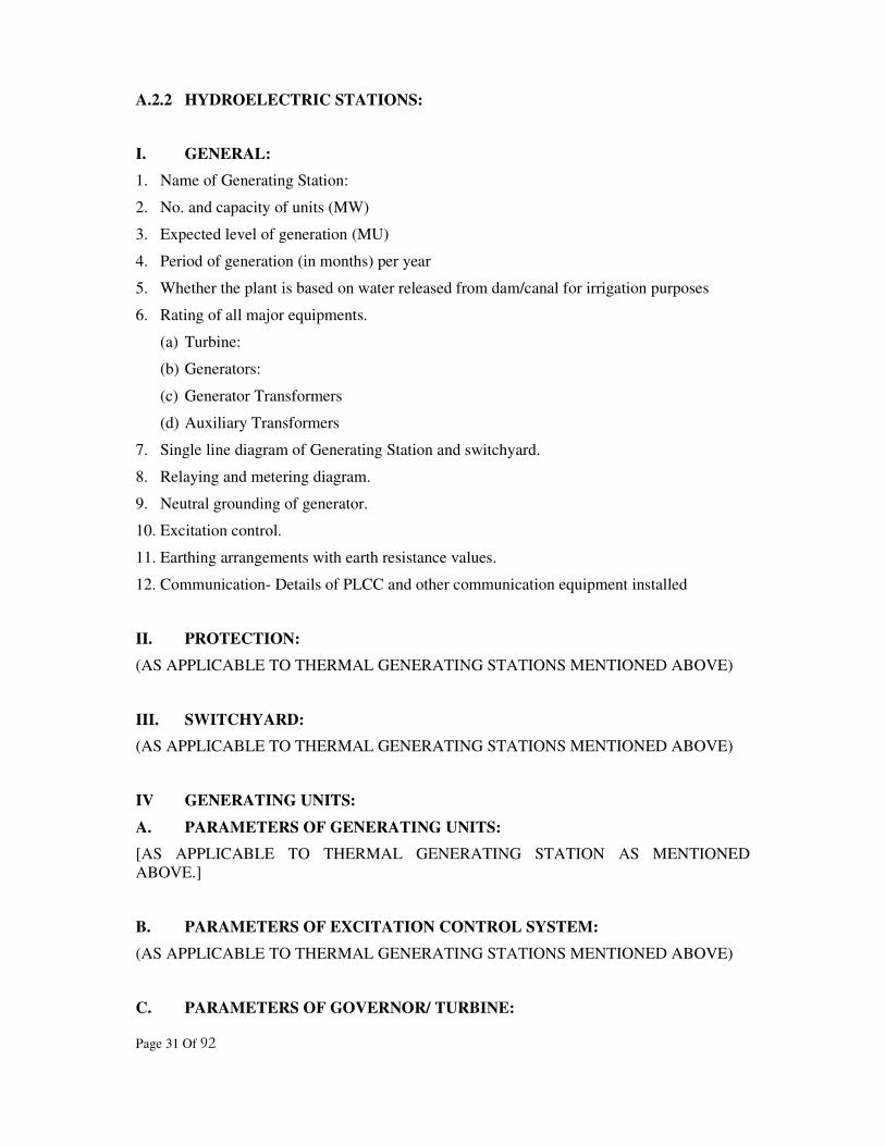
A.2.2 HYDROELECTRIC STATIONS:
I. GENERAL:
1. Name of Generating Station:
2. No. and capacity of units (MW)
3. Expected level of generation (MU)
4. Period of generation (in months) per year
5. Whether the plant is based on water released from dam/canal for irrigation purposes
6. Rating of all major equipments.
(a) Turbine:
(b) Generators:
(c) Generator Transformers
(d) Auxiliary Transformers
7. Single line diagram of Generating Station and switchyard.
8. Relaying and metering diagram.
9. Neutral grounding of generator.
10. Excitation control.
11. Earthing arrangements with earth resistance values.
12. Communication- Details of PLCC and other communication equipment installed
II. PROTECTION:
(AS APPLICABLE TO THERMAL GENERATING STATIONS MENTIONED ABOVE)
III. SWITCHYARD:
(AS APPLICABLE TO THERMAL GENERATING STATIONS MENTIONED ABOVE)
IV GENERATING UNITS:
A. PARAMETERS OF GENERATING UNITS:
[AS APPLICABLE TO THERMAL GENERATING STATION AS MENTIONED
ABOVE.]
B. PARAMETERS OF EXCITATION CONTROL SYSTEM:
(AS APPLICABLE TO THERMAL GENERATING STATIONS MENTIONED ABOVE)
C. PARAMETERS OF GOVERNOR/ TURBINE:

Page 32 Of 92
(AS APPLICABLE TO THERMAL GENERATING STATIONS MENTIONED ABOVE)
D. OPERATIONAL PARAMETERS:
1. Minimum notice required for synchronising a Generating Unit from De-synchronisation.
2. Minimum time between synchronising different Generating Units in a Generating Station.
3. Minimum block load requirements on Synchronising.
A.3 Planning Data Generation
(For submission on request by STU)
A.3.1 FOR THERMAL GENERATING STATIONS, if desired by STU:
A. CONNECTION:
1. Report of studies of parallel operation with Transmission System:
(a) Load flow studies
(b) Stability studies
(c) Short Circuit studies
2. Proposed connection with Transmission system:
(a) Voltage
(b) No. of circuits
(c) Connection Point(s) / Interface Point(s)
II. HYDROELECTRIC GENERATING STATIONS:
(AS APPLICABLE TO THERMAL GENERATING STATIONS MENTIONED ABOVE)

Page 33 Of 92
PART - II - DISTRIBUTION
(To be furnished by the Distribution Company to STU)
B – 1 Standard Planning Data Distribution
I. GENERAL:
1. Single Line
Diagram
Licensee-wise upto 66kV Substations.
2. Consumer Data Furnish category wise number of Consumers, their connected
Loads to the best judgement of the Distribution Licensee
3. Reference to area offices presently in charge of the distribution
II. CONNECTION:
1. Connection Points/ Interface Points: Furnish single line diagram showing
Connection Points/ Interface Points.
2. Voltage of supply at Connection Points/
Interface Points:
3. Names of Grid Sub-Station feeding the
Connection Points/ Interface Points:
III. LINES AND SUB-STATIONS:
1. Line Data: Furnish length of line and voltages (EHV level)
2. Sub-station Data: Furnish transformer details of 220/ 11kV,132/11 kV, 66/22 kV,
66/ 11 kV Sub-stations, capacitor installations:
IV LOADS:
1. Loads drawn at
Connection Points/
Interface Points:
If the Distribution Licensee receive power at a number
of connection points in a compact area, which are
interconnected in a ring, then such Distribution Licensee
shall forward the overall load drawn for overall Area of
Supply as well as at each connection point with the
variation or tolerance as mutually discussed and agreed
upon with the STU.
2. Details of loads fed at
EHV if any:
Give name of Consumer, voltage of supply, contract
demand and name of Grid Sub-station from which line
is drawn, length of EHT line from Grid Sub-station to
Consumer's Premises.
V. DEMAND DATA (FOR ALL LOADS 5 MW AND ABOVE):
1. Type of Load & Rating in HP or KW: State whether furnace loads, rolling
mills, traction loads, other industrial

Page 34 Of 92
loads, pumping loads etc.
2. Rated voltage:
3. Electrical loading of equipment: State number and size of motors, rating
of arc furnaces/ induction furnace, types
of drive and control arrangements.
4. Sensitivity of load to voltage and
Frequency of supply:
5. Maximum harmonic content of Load:
6. Average and maximum phase unbalance
of Load:
7. Nearest Substation from which load is to
be fed:
8. Location map to scale: Map shall show the location of load with
reference to lines and sub-stations in the
vicinity.
VI LOAD FORECAST DATA:
1. Peak load for Connection Point/ Interface Point as well as peak load and energy forecast
for Area of Supply for each of the succeeding 10 years.
2. Details of methodology and assumptions on which forecasts are based.
3. Details of load 5 MW and above.
(a) Name of prospective Consumer.
(b) Phasing of load.

Page 35 Of 92
B – 2 Detailed Planning Data (Distribution)
I. GENERAL:
1. Schematic Single line diagram of Distribution System (showing distribution lines from
Connection Points/ Interface Points with Transmission System 220kV/ 11kV, 132/11 kV,
66/22 kV & 66/ 11 kV Substations, Consumer bus if fed directly from Transmission
System)
2. Numbering and nomenclature of lines and Substations (Identified with feeding Grid
Substations of the Transmission System and concerned 220kV/11kV, 132/ 11kV, 66/22
kV & 66/11 kV Substation).
II CONNECTION:
1. Connection Points/ Interface Points (Furnish details of existing arrangement of
Connection)
2. Details of metering of Connection Points/ Interface Points.
B.3 Detailed Planning Data (Distribution)
(For submission on request by STU)
I. CONNECTION:
1. Connection Points/ Interface Points as applied for
(a) New
(b) Upgrading existing connection
2. Changes in metering at Connection Points/ Interface Points
II. LOADS:
1. Details of major loads of 1 MW and above to be contracted for next ten years.

Page 36 Of 92
ANNEXURE B
PLANNING DATA REQUIREMENTS – TRANSMISSION (CLAUSE 4.5.2)
(To be furnished to the User on request by STU/ Transmission Licensee)
B – 1 Standard Planning Data (Transmission)
1. Name of the line: (Indicating
Generating Stations and Substations to
be connected)
2. Voltage of line (kV):
3. No. of circuits:
4. Route length (CKM):
5. Conductor sizes:
6. Line parameters (PU on 100 MVA
base or ohmic values):
Resistance/KM
Inductive Reactance /KM
Suceptance/KM
7. Approximate power flow MW &
MVAr:
8. Line Route (Topographic Sheets)
9. Purpose of connection: Reference to scheme, wheeling to other
States etc.
10. Approximate period of construction:

Page 37 Of 92
B – 2 Detailed System Data (Transmission)
I. GENERAL:
1. Single line diagram of the Transmission System up to 66 kV bus at grid sub-station:
2. Name of Substation
3. Generating Station connected
4. Number and length of circuits
5. Interconnecting Transformers
6. Substation bus layouts
7. Power transformers
8. Reactive compensation equipment
(a) The details of capacitors installed
(b) Additional capacitors to be commissioned along with additional loads.
9. Lightning arresters
10. Bus and/or line reactors
II. SUB-STATION LAYOUT DIAGRAMS SHOWING:
1. Bus bar layouts
2. Electrical circuitry, lines, cables, transformers, switchgear etc
3. Phasing arrangements
4. Earthing arrangements
5. Switching facilities and interlocking arrangements
6. Operating voltages
7. Numbering and nomenclature
(a) Transformers
(b) Circuits
(c) Circuit breakers
(d) Isolating switches
III. LINE PARAMETERS: (FOR ALL CIRCUITS)
1. Designation of line
2. Length of line (KM)
3. No. of circuits, size and type of conductor, thermal rating
4. Per circuit values
(a) Operating voltage (kV)
Page 38 Of 92
(b) Positive phase sequence reactance - ohms/KM
(c) Positive phase sequence resistance - ohms/KM
(d) Positive phase sequence suceptance - mhos/KM
(e) Zero phase sequence reactance - ohms/KM
(f) Zero phase sequence resistance - ohms/KM
(g) Zero Phase sequence suceptance - mhos/KM
IV. TRANSFORMER PARAMETERS: (FOR ALL TRANSFORMERS
SUBSTATIONWISE)
1. Rated MVA
2. Voltage ratio
3. Vector group
4. Positive sequence reactance on rated MVA base (Max., min. & normal)
5. Positive sequence resistance on rated MVA base (max., min. & Normal)
6. Zero sequence reactance on rated MVA base
7. Tap change range (+% to -%) and steps
8. Details of tap changer (OFF/ON)
9. Neutral grounding transformer/resistor values
10. % Impedance (Max/Min/Normal Tap)
V. EQUIPMENT DETAILS: (FOR ALL SUB-STATIONS):
1. Circuit breakers
2. Isolating switches
3. Current transformers
4. Potential transformers
5. Lightning arresters
6. Earthing switches
VI RELAYING AND METERING:
1. Relay protection installed for all transformers and feeders along with their settings and
level of co-ordination with other users.
2. Metering Details:
VII SYSTEM STUDIES:

Page 39 Of 92
1. Load flow studies (Peak and lean load for maximum Hydro and maximum Thermal
Generation)
2. Transient stability studies for 3 Phase fault in critical lines, and single pole reclosing for
400 kV Lines.
3. Dynamic stability studies
4. Short circuit studies ( 3 Phase and single Phase to earth)
5. Transmission and distribution losses in the system.
VIII DEMAND DATA: (FOR ALL SUB-STATIONS)
1. Demand Profile (Peak and off Peak load)
(a) Forecast for next 5 years
IX REACTIVE COMPENSATION EQUIPMENT:
1. Type of equipment (fixed or variable)
2. Capacities and/or inductive rating (Voltage and MVAr) or its operating range.
3. Details of control
4. Connection Point/ Interface Point to the system.
B.3 Detailed Planning Data (Transmission)
I. CONNECTION:
1. Single Line Diagram showing position of connection
2. Sub-station layout diagram
(a) New
(b) Addition and Alteration
3. Revised system studies with changed parameters
4. Connection Point/ Interface Point
(a) Voltage
(b) Length of circuit
(c) Circuit parameters
(d) PLCC facilities
(e) Relaying with inter tripping arrangements to inter trip system breaker at Connection
Point/ Interface Point to isolate on fault
(f) Metering at Connection Point/ Interface Point.
(g) Other communication facility
***
Page 40 Of 92
SECTION-5
CONNECTIVITY CONDITIONS
5.1 INTRODUCTION:
5.1.1 This section of the Grid Code formulates the technical, design and operational criteria
to be complied with by the new User or Users modifying the existing Transmission
System.
5.2 OBJECTIVE:
5.2.1 The objective of this section is to ensure the following:
(a) All Users or prospective Users are treated equitably.
(b) Any new Connection shall not impose any adverse effect on the existing Users as
well as new Connections shall not suffer adversely due to existing Users.
(c) A System of acceptable quality is ensured by specifying the required minimum
standards for the design and operational criteria to assist the Users in their
requirement to comply with the Licence obligations.
(d) The ownership and responsibility for all the items of equipment is clearly
specified in the "Site Responsibility Schedule" for every site where a connection
is made.
5.3 SITE RESPONSIBILITY SCHEDULE:
5.3.1 For every connection to the Transmission System for which a connection agreement is
required, the Transmission Licensee shall prepare a Schedule of Equipment, pursuant
to the relevant Connection Agreement, with the information supplied by the Users.
This Schedule, called a "Site Responsibility Schedule" shall state the following for
each item of equipment installed at the Connection Site: -
(a) Ownership of the plant/Apparatus.
(b) Responsibility for control of plant/Apparatus.
(c) Responsibility for operation of plant/Apparatus.
(d) Responsibility for maintenance of plant/Apparatus.
(e) Responsibility for all matters relating to safety of any person at the Connection /
Interface Site.
(f) The management of the Connection / Interface Site.
5.3.2 Each Site Responsibility Schedule, in addition to the above, shall contain all other
information setout in the Grid Code. An illustrative "Site Responsibility Schedule" is
furnished in the Annexure "C".

Page 41 Of 92
5.3.3 The User owning the Connection/ Interface Site shall provide reasonable access and
other required facilities for other Users whose equipments are installed/to be installed
at the Connection/ Interface Site for installation, operation and maintenance etc.
5.4 SYSTEM PERFORMANCE:
5.4.1 The design and construction of all the equipment connected to the Transmission
System shall satisfy the relevant Indian Standard Specifications. In case of equipment
for which the Indian Standard Specifications do not exist, the appropriate IEC, or
IEEE or other International Standards shall apply.
5.4.2 Installation of all electrical equipment shall comply with IE Rules, 1956 which are in
force for time being and will be replaced by new rules made under Electricity Act,
2003.
5.4.3 For every new Connection sought, the Transmission Licensee shall specify the
Connection Point /Interface Point and the supply voltage, along with the metering and
protection requirements as specified in the "Metering and Protection Standard" under
Attachment - 2.
5.4.4 The operation of the Transmission System shall be in accordance with the
"Transmission System Operating Standard" under Power System Management &
Operation Standard. The User shall however be subject to the grid discipline
prescribed by the SLDC and WRLDC.
5.4.5 The insulation co-ordination of the Users' equipment shall conform to the applicable
Indian Standards/code of practices. The rupturing capacity of the switchgear shall not
be less than that notified by the Transmission Licensee based on system studies.
5.4.6 The equipment for data transmission and communications for all the Generating
Stations existing at the time the Grid Code comes into effect shall be owned and
maintained by STU/ Transmission Licensee unless alternative arrangements are
mutually agreed to. For new Generating Stations the same shall be owned and
maintained by STU/ Transmission Licensee, unless otherwise mutually agreed to by
the Generating Company.
5.5 CONNECTION POINTS / INTERFACE POINTS:
5.5.1 Generating Company/ CPP: The voltage at the Connection Point/ Interface Point with
the Transmission System may be 400/220/132/66/22/11 kV or as agreed with STU/
Transmission Licensee. The Connection Point / Interface Point shall be the outgoing
feeder gantry point of the Generating Station switchyard/ CPP. The Metering Point
shall be the outgoing feeder. All the protection and metering equipment within the
perimeter of the Generating Station/ CPP shall be owned and maintained by the
Generating Company/ CPP respectively. From the outgoing point onwards, the
Transmission Licensee shall maintain all the equipment.
Page 42 Of 92
5.5.2 Distribution Licensee: The voltage at the Connection Point/ Interface Point to the
Transmission System may be as specified by the Distribution Licensee. The
Connection Point / Interface Point shall be the outgoing feeder gantry of the
Transmission Licensee's Substation. The metering point shall be at 11/ 22 kV side of
power transformer at Transmission Licensee’s Substation. However, the metering
point shall be at the outgoing feeder of substation for supply to two or more
Distribution Licensees from the same Substation. The Connection Point / Interface
Point to the Transmission System and metering point shall be incoming feeder gantry
of Distribution Licensee’s Substation, when the voltage at the Connection Point/
Interface Point is 66kV or above. All the terminal equipment for communication,
protection and metering within the Premises of the Transmission Licensee shall be
owned and maintained by the Transmission Licensee. The respective Distribution
Licensees shall maintain all the equipment from the Connection Point/ Interface Point
onwards.
5.5.3 Connections with other Transmission Systems: - The connection, metering and
protection scheme, metering point and the voltage for the Western Regional
Transmission System shall be in accordance with the mutual agreement between the
CTU and STU/ Transmission Licensee. The connection for other neighbouring state
transmission systems or any other Transmission Licensees shall also be in accordance
with the mutual agreement between the concerned Licensees.
5.5.4 EHV Consumers: - The standard voltage can be as agreed to by the
Transmission/Distribution Licensees. The Connection Point/ Interface Point shall be
the feeder gantry on their Premises. The metering point for the sale of power to the
EHV Consumers shall be at the Connection Point/ Interface Point with their systems.
5.6 PROCEDURE FOR APPLICATIONS FOR CONNECTIONS TO THE
TRANSMISSION SYSTEM:
5.6.1 Any User seeking to establish new or modified arrangements for connection to and/or
use of the Transmission System shall submit the following report, data and
undertaking along with an application and prescribed fee as decided by GERC duly
observing the procedural requirements to the Transmission Licensee:
(a) Report stating the purpose of the proposed connection and/or modification,
connecting site, description of apparatus to be connected or modification to the
Apparatus already connected.
(b) Applicable data along with the data listed in the Annexe A and B of Section 4.
(c) Confirmation that the prospective installation complies with the provisions of IE
Rules 1956, which are in force for time being and will be replaced by new rules
made under Electricity Act, 2003 and Electricity Act, 2003.
(d) Construction Schedule and target completion date.
(e) An undertaking to the effect that the User shall abide by the Grid Code, IEGC and
the provisions of IE Rules 1956, which are in force for time being and will be

Page 43 Of 92
replaced by new rules made under Electricity Act, 2003, for installation and
operation of the Apparatus.
(f) For special loads like arc furnaces, rolling mills etc., Real and Reactive Power
values of the Load with time and harmonic level.
5.6.2 The Transmission Licensee shall make a formal offer to the User within fifteen days
from the date of receipt of application. The formal offer shall contain all the above
information along with any such information as may be reasonably required. The
break-up cost of the works to be undertaken shall be furnished duly classified under
the sub-heads like materials, labour and supervision. The offer made shall be subject
to obtaining or in compliance with the required consents, approvals, permissions for
right of way or other requirements, whether of statutory or contractual nature or
otherwise.
5.6.3 An User whose development requires the Transmission Licensee to obtain any of the
consents, approvals, permissions, and right of ways or to comply with any other
requirements mentioned in this Grid Code shall:
(a) Provide necessary assistance, supporting information or evidence; and
(b) Ensure attendance by such witnesses as the Transmission Licensee may
reasonably request.
5.6.4 The estimated time schedule for completion of such works should also be identified
taking into account the time required to obtain statutory clearances etc., wherever
necessary. In respect of offers for modifications to the existing Connections, the offers
shall also take into account the terms of the existing Connection Agreement.
5.6.5 If the nature of complexity of the proposed development is such that the prescribed
time limit for making the offer is not considered adequate, the Transmission Licensee
shall make a preliminary offer within the prescribed time limit indicating the extent of
additional time required for more detailed analysis of the issues.
(a) On receipt of the preliminary offer, the User shall indicate promptly whether the
Transmission Licensee should proceed further to make a final offer within the
extended time limit.
(b) If necessary, the Transmission Licensee may require the User to furnish some or
all of the detailed planning data at this stage itself in advance of the normal time
limit.
5.6.6 All offers (other than the preliminary offers) including revised offers shall remain
valid for 120 (one hundred and twenty) days from the date of issue of the offer. The
Transmission Licensee shall make a revised offer, upon request by a User, if
necessitated by changes in data furnished earlier by the User.
5.6.7 The User shall furnish the relevant Detailed Planning Data to the Transmission
Licensee within thirty days of acceptance of an offer or such longer period as the
Transmission Licensee may agree in a particular case.
5.6.8 Wherever the State Power Grid is connected with the Inter State Transmission
System, the provisions of Connection Conditions of IEGC will prevail.
Page 44 Of 92
5.7 RIGHT TO REJECT AN APPLICATION:
5.7.1 The Transmission Licensee may reject any application for connection to and/or use of
the Transmission system under the following conditions:
(a) If the proposed connections violate any provisions under the Transmission
License,
(b) If the proposed works stated in the application do not lie within the purview of the
Licence or do not conform to the provisions of the Grid Code,
(c) If the applicant fails to give the undertakings according to clause 5.6.1 of this
section.
5.7.2 In the event of an offer becoming invalid or rejected by an applicant within the
validity period, no further action shall be taken by the STU/ Transmission Licensee on
the Connection applications unless it is substantially different from the original
application with regard to the system changes.
5.8 CONNECTION AGREEMENTS:
5.8.1 A connection agreement, or the offer for a connection agreement, shall include, as
appropriate within its terms and conditions, the following:
(a) A condition requiring both the parties to comply with the Grid Code.
(b) Details of connection and/or use of the system.
(c) Details of any capital related payments and any other payments and deposits etc.,
arising from necessary reinforcement or extension of the System.
(d) A "Site Responsibility Schedule" detailing the division of responsibility at the
Connection Sites in relation to ownership, control, operation and maintenance of
Plant and Apparatus and to safety of persons.
5.8.2 If any offer was originally made upon an application for development by a User,
which is subject to changes in the design parameters, the Transmission Licensee shall
make a revised offer to the User including revised terms and extended time limit for
submission of data. This revised offer shall form the basis of any connection
agreement.
5.9 METERING FOR OPEN ACCESS:
5.9.1 The open access consumer, Generating company, Distribution licensee and traders
shall provide Meters, as may be specified by the Commission for such consumer
based on voltage, point and period of supply and tariff category (as also incorporated
in Grid Code) as per the Gujarat Electricity Regulatory Commission (Open Access in
Intra-state Transmission & Distribution) Regulations, 2004.
5.10 The term ‘Meter’ shall include Current transformers, voltage/potential transformers,
wiring between them and meter box/panel.

Page 45 Of 92
ANNEXURE C
SITE RESPONSIBILITY SCHEDULE (CLAUSE 5.3.2)
Name of the Generating Station/substation owner:
Telephone No:
Fax No:
Permanent Address:
Responsibility for Item of Plant or
Apparatus
Plant
Owner Safety Control Operation Maintenance
Remarks
----- kV
Switch Yard *
Feeders
Generating Units
*All HV Apparatus on any Connection Site shall be shown on one schematic diagram, which
shall include details of the following:
1. Busbars
2. Circuit breakers
3. Isolator
4. Bypass facilities
5. Earthing switches
6. Earth Pits
7. Overhead line entry / gantry
8. Overhead line tapping
9. Cable and cable sealing ends
10. Generating Unit
11. Generating Unit Transformers
12. Generating Unit Auxiliary Transformers including Low Voltage Circuit Breakers
13. Station Service Transformers including Low Voltage Circuit Breakers
14. Capacitors including Synchronous Condensers
15. Series or shunt reactors
16. Grid transformers (Inter Connecting Transformers)
17. Tertiary windings
18. Earthing and Auxiliary Transformers
19. Three phase voltage transformers
20. Single phase voltage transformers and phase identity

Page 46 Of 92
21. Surge arresters
22. Neutral earthing arrangements on HV Plant
23. Current transformers
24. Potential Transformer
25. Equipments related to PLCC and SCADA.
***
Page 47 Of 92
SECTION-6
OPERATION PLANNING AND SECURITY
6.1 INTRODUCTION:
6.1. This section contains the guidelines for STU/ Transmission Licensee to carry out the
planning of power system operation, including interface co-ordination with the Users,
fixing the parameters for Operation Margin, contingency reserve, demand control etc.,
for a satisfactory grid operation and system integrity.
6.2 OBJECTIVE:
6.2.1 The objective of this section is to define the process, which will allow STU to
minimise transmission outages by co-ordination with the Generating Companies and
other Users' outages while maintaining system security to the extent possible. This
section also provides guidelines for setting out reserves available from:
(a) External connections,
(b) System operation and
(c) Demand control.
6.3 DEMAND ESTIMATION:
6.3.1 The Distribution Licensee shall formulate a short-term Demand forecast considering
the previous financial year as base and projecting the Demand for the succeeding 5
years. During this process, he shall review the status of Loads materialising as per the
previous Load forecast. Energy sales in each tariff class shall be projected in the
forecast period over the corresponding figures relating to the base year by adopting an
appropriate statistical method. The projections shall take into account the assumed
normal growth for non-specific Loads, specific and identified loads of 1 MW and
above. The projections shall also take into account the effects of Demand Side
Management, if any, and energy conservation. The peak load requirements at each
Connection Point / Interface Point shall be estimated taking into account the
distribution losses. The peak load requirement at each Connection Point / Interface
Point will essentially ensure that the STU/ Transmission Licensee may determine the
corrective/ necessary measures to be taken to maintain the capacity adequacy in the
Transmission System upto the Connection Point / Interface Point. This will facilitate
the Transmission Licensee to develop the compatible Transmission System. However,
if the Distribution Licensee receives power at a number of Connection Points /
Interface Points in a compact area, which are interconnected in a ring, then such
Distribution Licensee shall forward the overall long term Demand forecast as well as
at each Connection Point / Interface Point with the variation or tolerance as mutually
discussed and agreed upon with the STU/ Transmission Licensee. The aggregate
energy and peak load requirements for the Area of Supply shall be estimated taking
into account the distribution losses. The Distribution Licensee shall forward the short

Page 48 Of 92
term demand forecast for each Connection Point / Interface Point for peak Load
requirement as well as aggregate energy and peak Load demand for Area of Supply
on annual basis to the STU, Transmission Licensee and GERC along with the
following details on the basis of which the forecast is made.
(a) Data,
(b) Methodology,
(c) Assumptions
6.3.3 It shall be the responsibility of all the Distribution Licensees and Union Territories
(Diu, Daman and Dadara Nagar Haveli) to the extent, it affects the Gujarat State Grid,
to fully co-operate with STU in preparation of Demand forecasts for the entire Gujarat
State.
6.3.4 The Distribution Licensees shall provide their above mentioned estimates for the
period from 1st April to 31st March by 31
st January of each year on a financial year
ahead basis. This shall be updated for every month subsequently in the previous
month on month ahead basis, and in the previous day on day ahead basis as required
by STU/ Transmission Licensee.
6.3.5 Based on the data furnished by the Distribution Licensees, STU shall make monthly
peak and lean period demand estimates for the year ahead, and daily peak and lean
period demand estimates for the month ahead.
6.3.6 The Distribution Licensees shall provide to SLDC, estimates of loads that may be
shed, when required, in discrete blocks with details of arrangements of such load
shedding.
6.3.7 All the data shall be collected in accordance with the procedures agreed to between
STU and each User.
6.3.8 The SLDC shall maintain a database of the total demand for the State on an hourly
basis.
6.4 DATA REQUIREMENTS:
6.4.1 The Users and STU shall provide all the data indicated in the Annexure D to the
SLDC. Each Generating Company shall submit to the SLDC in writing during the
month of March every year, the Generation Planning Parameters and the performance
chart of the Generator to be applied from the beginning of April onwards, for the
entire year. The Generator Performance chart shall be for each specific Generating
Unit and include the details of the Generator Transformers and demonstrate the
limitation of reactive capability of the Generating Unit at the Transmission System
voltage of 10% above normal as and when required by the SLDC.
Page 49 Of 92
6.5 RELEASE OF CIRCUITS AND GENERATOR UNITS INCLUDED IN THE
OUTAGE PLAN:
6.5.1 Notwithstanding provision in any approved outage plan, no cross boundary circuits or
Generating Units of a Generating Company shall be removed from service without
specific release from the SLDC. This restriction shall not apply to individual
Generating Units of a CPP, which are operating in standalone mode. Once an outage
has commenced, and if any change in restoration is apprehended, the SLDC or the
User concerned shall inform the other party promptly together with the revised
estimation of restoration time.
6.6 TRANSMISSION OUTAGE PLANNING:
6.6.1 The STU shall produce a yearly transmission Outage program for the period from 1st
of April to 31st of March. All the Generating Companies and Distribution Licensees
shall furnish, their proposed outage programs containing the identification of the Unit,
Substation, etc., date of start of outage and duration of outage, in writing to the SLDC
for the year ahead (from 1st of April to 31st of March) by 15
th of October each year. In
case the Distribution Licensee has planned their internal outage program in such a
way, which may induce a loss of load not exceeding 20 MW in his Area of Supply,
such outage progam may not be required to be intimated to SLDC. The SLDC shall
interact with all the above said agencies and prepare an optimum draft outage plan to
minimise interruptions to Consumers to the extent possible, if necessary by
rescheduling any of the outages. The finally agreed transmission outage plan, taking
into account the regional and user requirements shall be prepared by the SLDC and
furnished to all the Users by the 15th
of February every year.
6.6.2 The outage plan shall be reviewed by the SLDC quarterly and monthly basis in
consultation with all the concerned agencies mentioned above regarding any changes
necessitated during the period and the revised outage plan shall be intimated to all the
Users. The Users’ requests for additional outages, if any, shall be considered by the
SLDC and accommodated to the extent possible. Such changes shall be informed by
the SLDC promptly to all the concerned. The Distribution Licensees shall also inform
the Consumers through publications in local newspapers whenever interruptions to
power supply would affect them.
6.7 OPERATING MARGIN:
6.7.1 Operating Margin comprises of Contingency Reserve and Operating Reserves
required for the satisfactory operation of the power system to cover uncertainties in
variations in Demand forecasts, loss of external connections, loss of generation,
constraints in the Transmission System and all other factors.
6.7.2 The required Contingency Reserve shall be decided by the SLDC on the basis of
historical trends in the reduction of availability of the Generating Companies, imports
through inter-state tie lines and increases in Demand forecast during real time
operation.

Page 50 Of 92
6.7.3 Whenever the Contingency Reserve is to be held by a Thermal Power Station, the
SLDC shall include the same in the Indicative running notification and/or subsequent
dispatch instructions by which the Generating Company is notified of and/or
instructed, that the Generating Unit shall be operated in the Contingency Reserve
mode.
6.8 DEMAND CONTROL:
6.8.1 Automatic load shedding shall be resorted to by means of installation of the Under
Frequency Relays at the Substations of the Transmission Licensee as per the
directions of the SLDC to preserve the overall integrity of the power system. The
number and size of the discrete blocks with the associated Low Frequency setting
predetermined for Automatic Under Frequency Load Shedding shall be determined on
rotational basis in consultation with every Distribution Licensee. The frequency
settings of these relays shall be co-ordinated in consultation with the Regional Power
Committee.
6.8.2 Whenever restoration of large portions of the total Demand disconnection effected by
the automatic load shedding is not possible within a reasonable time, the SLDC shall
implement additional disconnection manually, to restore an equivalent amount of
Demand disconnected automatically. Each Distribution Licensee shall help the SLDC
in identifying such load blocks. Load shed by the operation of automatic load
shedding devices shall not be restored without specific directions from the SLDC.
6.8.3 Planned manual Disconnection shall be implemented by the SLDC when there is a
shortfall in generation, or constraints in Transmission System, or reduction of imports
through external connection etc., requiring Demand Control over prolonged period to
control the overdrawal of power from ISGS when the system frequency falls below
49.5 Hz. In such cases a rotational load shedding scheme shall be adopted to ensure
equitable treatment for all Consumers as far as practicable.
6.8.4 Emergency Manual Disconnection to deal with unacceptable voltage and frequency
levels etc shall be implemented by the SLDC only when loss of generation, mismatch
of generation with the Demand or constraints in the Transmission System, as well as
in case of overdrawal from the grid in excess of respective schedule affecting the
frequency of the regional grid below 49 Hz, result in an emergency situation,
requiring load shedding at short notice or no notice, to maintain a regulating margin.
6.8.5 These control measures shall not be withdrawn till the system frequency improves and
when the SLDC issues such instructions after review of the situation.
6.9 SYSTEM SECURITY:
6.9.1 All Users shall co-operate with STU / Transmission Licensee so that the respective
sections of the power system operate in synchronism with Gujarat Power Grid.

Page 51 Of 92
STU/Transmission Licensee/ CTU shall operate the inter-state links and ensure
smooth exchange of power in the Western Grid among the Constituent State Grids.
6.9.2 The Transmission System shall not be isolated from the Western Grid except under
the following conditions:
(a) Emergency situations that may result in the total grid collapse.
(b) Isolation of the system to prevent serious damage to equipment.
(c) Instructions of the SLDC or the WRLDC under operating conditions.
(d) Operation of updated under frequency/islanding scheme as approved at western
region level.
6.9.3 Complete synchronism shall be restored as soon as the conditions permit. The
restoration process shall be supervised by the SLDC.
6.9.4 The Transmission Lines of 132 kV and above, 66 kV lines meant for connecting CPP
with grid and the Inter Connecting Power Transformers should not be opened without
instructions or prior clearance from the SLDC/ ALDC unless under emergencies
when prior clearance is not possible. The SLDC shall also be informed and get the
clearance, while bringing back these lines into service.
6.9.5 Any tripping of the Transmission Lines 132kV and above or power transformers of
132 kV class (i.e. 132/66kV etc.) and above and 50 MVA and above whether actuated
by protective relays or manually, shall be promptly reported to the SLDC/ALDC by
the Engineer in Charge of the Substation at the earliest along with the reasons for such
tripping and the time required for restoration. The report shall accompany all the
relevant information/data including the outputs of the disturbance recorder, sequential
event recorder etc., required for the purpose of analysis. While the restoration of
tripped equipment/ line, SLDC shall be informed and get the clearance.
6.9.6 The governors of all the Generating Units of capacity 50 MW and above, for Hydro
Generating Station and 200MW and above for thermal Generating Station except run
of the river hydroelectric Generating Stations without pondage, steam turbines of
combined cycle gas turbines and nuclear Generating Stations, shall be in free
operation at all times irrespective of ownership of Generating Unit. If for any reason,
the governors are locked, the same should be intimated to the SLDC along with the
reasons and duration of such operation. Based on the same, SLDC shall advise
WRLDC about such an operation alongwith the reasons and duration thereof. The
load limiter, automatic turbine run-up system (ATRS), turbine supervisory
coordinated control system etc shall not be used to suppress the normal governor
action in any manner. No dead bands and time delays shall be deliberately used. All
governors shall have a droop of 3% to 6%.
6.9.7 All Generating Units shall be capable of and shall not be prevented from picking up
5% extra load, more than the declared Maximum Continuous Rating, for at least five
minutes or within the technical limits specified by the manufacturers, when the
frequency falls due to a system contingency. In case any Generating Unit of 50 MW
and above does not meet this requirement for any period, the Generating Company
should intimate the same to the SLDC alongwith reasons thereof.

Page 52 Of 92
6.9.8 In case the frequency falls below 49.5 Hz, all the partly loaded Generating Units shall
pick up additional load at a faster rate, according to their capability. The SLDC in
consultation with the WRLDC and the Distribution Licensees including AECo. &
SECo. shall prepare a plan for automatic load relief during the low frequency
conditions. In case the frequency rises to 50.5 Hz or higher, neither any Generating
Unit which is in stand by mode shall be synchronised with the Grid nor Active Power
generation at any generating station shall be increased irrespective of the type and
ownership, unless advised by SLDC.
6.9.9 No Generating Company shall suddenly increase/decrease its generation by more than
50 MW without prior intimation to the SLDC except during emergencies or to prevent
an imminent danger to any costly equipment. Similarly no Distribution Licensee shall
cause a sudden decrease/increase in its load due to imposition/lifting of power cuts
etc., without prior intimation and consent of the SLDC, particularly when the
frequency is less than 49.5 Hz or above 50.5 Hz.
6.9.10 All Generating Units shall have Automatic Voltage Regulators in operation, with
appropriate settings. If for any reason it has to be operated without the same, the
SLDC shall be intimated immediately with reasons and duration of such operation and
its concurrence obtained. The metering and protection systems shall be provided
according to the "Metering and Protection Standard" (Attachment – 2).
6.9.11 Users shall comply with the following applicable standards issued separately:
(a) Power System Management and Operation Standard.
(b) Supply Code
(c) Distribution Code.
(d) Power System Safety Standards
6.9.12 The Users shall make all possible efforts to ensure that the grid frequency always
remains within the 49.0 - 50.5 Hz band, the frequency range within which the steam
turbines conforming to the IEC specifications can safely operate.

Page 53 Of 92
ANNEXURE D
OPERATION PLANNING DATA (CLAUSE 6.4.1)
A OUTAGE PLANNING DATA:
I Demand Estimates:
(a) Estimated aggregate annual sales of energy in million units and peak and lean
Demand in MW and MVAr in the Area of Supply for the next financial year from
1st April to 31
st of March shall be submitted before October 15.
(b) Estimated aggregate monthly sales of energy in million units and peak and lean
demand in MW and MVAr in Area of Supply for the next month shall be
submitted before 15th of current month.
(c) Hourly demand estimates for the day ahead shall be submitted by Distribution
Licensee to SLDC at 09.00 hours every day.
II. Estimates of load shedding:
(a) Details of discrete load blocks that can be shed to comply with instructions issued
by the SLDC when required, from each Connection Point / Interface Point soon
after connection is made.
III. Year ahead outage program:
(For the period 1st April to 31st March)
(a) Generating Companies outage program:
Information shall be furnished by 15th
October each year:
(i) Identification of Generating Unit.
(ii) MW, which will not be available as a result of outage.
(iii)Preferred start dates and start-time or range of start dates and start times and
period of outage.
(iv) If outages are required to meet statutory requirements, then the latest date by
which outage must be taken.
(b) WRLDC's Year ahead outage program:
(Affecting Transmission System)
Information shall be furnished as draft annual outage plan by 31st December and
final annual outage plan by 31st January.
(i) MW, which will not be available as a result of outage from Imports through
external connections including ISGS.
(ii) Start-Date and Start-Time and period of outage.
(c) CPP's Year ahead outage program:
Information to be furnished by 15th
October of each year:
Page 54 Of 92
(i) MW which will not be available as a result of outage.
(ii) Start-Date and Start-Time and period of outage.
(d) Distribution Licensee’s Year ahead outage program:
Information shall be furnished by 15th
October of each year (Not pertaining to internal
distribution network maintenance which is not substantially affecting the loading on
the Transmission Licensee’s lines):
(i) Load in MW not to be availed from each Connection Point / Interface Point as
well as Area of Supply in case of radial feeder and if the Distribution System
is connected in ring, the Distribution Licensee shall furnish Load in MW not
to be availed for his Area of Supply.
(ii) Period of suspension of drawal with Start-date and Start-time.
(e) Advance intimation required for outage for construction of new EHV lines and
maintenance due to any unforeseen trouble , but which can be planned & not of
extreme nature; shall be given by the Transmission Licensee / Distribution
Licensee to SLDC as under
Line Voltage Days Advance Notice
66 kV 7
132 kV 7
220 kV 10
400 kV 15
In case, if extreme emergency outage can avail after consulting SLDC for these
lines.
B GENERATION SCHEDULING DATA:
Schedule and dispatch shall be submitted by:
(a) Day ahead hourly MW/MVAR availability (0.00 - 24.00 Hrs.) of all Generating
Units at 09.00 Hrs. every day.
(b) Day ahead hourly MW import/export from CPP's and Generating Units owned by
Distribution Licensee of all Generator Units at 09.00 Hrs. every day.
(c) Status of Generating Unit AVR in service (Yes/No) of all Generating Units at
09.00 Hrs. every day.
(d) Status of Generating Unit speed controls system governor in service (Yes/No) of
all Generating Units at 09.00 Hrs. every day.
(e) Backing down capability with/without oil support (MW) of all thermal Generating
units at 09.00 Hrs. every day.
(f) Hydro Reservoir level & restrictions for all Generating Units at 09.00 Hrs. every
day.

Page 55 Of 92
(g) Generating Units Hourly summation outputs of all Generating Units at 09.00 Hrs.
every day.
(h) Day ahead hourly MW entitlements from Central Sector Generation at 11.00 Hrs.
every day.
C. CAPABILITY DATA:
(a) Generators shall submit to SLDC up to date capability curves for all Generating
Units on receipt of request from SLDC.
(b) CPPs shall submit to SLDC net return capability that shall be available for
export/import from Transmission system on receipt of request from SLDC.
D. RESPONSE TO FREQUENCY CHANGE:
(a) Primary Response in MW at different levels of loads ranging from minimum
Generation to registered capacity for frequency changes resulting in fully opening
of governor valve.
(b) Secondary Response in MW to frequency changes.
E. MONITORING OF GENERATION:
(a) Logged readings of Generators to the SLDC whenever required.
(b) Detailed report of Generating Unit tripping on monthly basis.
F. ESSENTIAL AND NON-ESSENTIAL LOAD DATA:
(a) Schedule of essential and non-essential Loads on each discrete load block for
purposes of load shedding shall be furnished as soon as possible after connection.
G. PROTECTION DATA:
(a) Generators/CPP's shall submit details of protection requirement and schemes
installed by them as per detailed planning data.
(b) The Transmission Licensee shall submit details of protection equipment and
schemes installed by them.
(c) Detailed system data required for relaying and metering of the Transmission lines
and Substations in relation to connection with any User as per detailed planning
data.
H. METERING DATA:
(a) Generators/CPPs shall submit details of metering equipment and schemes
installed by them.
(b) Detailed planning data
(c) STU/ Transmission Licensee shall submit details of metering equipment and
schemes installed by them.
***
Page 56 Of 92
SECTION-7
SYSTEM OPERATION METERING, PROTECTION, DESPATCH AND
CONTROL
7.1 INTRODUCTION:
7.1.1 This section specifies the procedure to be adopted for the scheduling of despatch of
the Generating Units to meet the demand and drawal allocations, the management of
frequency and voltages in the EHV system, the minimum requirement of protection
levels and metering specifications for the various components of the system.
7.2 OBJECTIVE:
7.2.1 The main objective of this section is to formulate the detailed methodology to be
followed by STU/ Transmission Licensee for healthy operation of the system to meet
the specified standards of electrical power under normal operating conditions as
follows:
(a) Laying down the procedures for the function of SLDC,
(b) Defining the responsibilities of the Transmission Licensee and other Users,
(c) Specify the minimum standards of protection to be employed in the Generating
Stations, Substations, and Transmission and Distribution Systems by the
concerned agencies.
7.3 GENERAL:
7.3.1 It is essential that all the Users of the Transmission System shall fully co-operate with
STU/ Transmission Licensee to maintain the System integrity and healthy operation.
The entire Grid is one unit right from the point of generation to the ultimate
consumers and the various agencies involved in the management of the power system
shall provide a healthy coordination to the SLDC who will be the central agency for
operation of the State Grid. The success or failure of the power system entirely
depends on the full cooperation of all the participants in this endeavour.
7.4 SYSTEM OPERATION AND DESPATCH:
7.4.1 STU shall operate and maintain the SLDC fully equipped for an optimum and reliable
operation of the power system, until the State Government does not notify any
government company or any authority or co-operation to operate SLDC in line with
the provisions given in Section – 31 of Electricity Act, 2003.
7.4.2 The estimation of daily Load Demand on day ahead basis shall be carried out, in
general, and furnished to the SLDC by the Distribution Licensees keeping in view the
following aspects:
(a) Outage Planning/Scheduled rostering,
(b) Historical data of load for the same month/day/time,

Page 57 Of 92
(c) Previous day's Demand,
(d) Present weather conditions and meteorological reports,
(e) Requirement of meeting important Loads on festivals etc.,
(f) Force Majeure conditions such as cyclones, earthquake, riots etc.,
(g) Vacations, Sundays and other holidays,
(h) Number and frequency of breakdowns and their recovery period.
7.4.3 All the Generating Companies shall furnish their generator availability details of the
quarter hourly MW/MVAr/Maximum MWhrs by 9.00 Hrs. of each day for the next
day.
7.4.4 The Despatch instructions shall be issued by the SLDC by the telephone message/fax
message/e-mail and contain the following:
(a) Specific Generating Company to which the instruction applies,
(b) The output to which the instruction applies,
(c) The start time wherever the same is different from the time the instruction is
issued,
(d) Issue time of instruction,
(e) Name of the sender of despatch instruction,
7.4.5 The "Power Supply Management and Operation Standard” under Power Generation
Section specifies the procedures for the following aspects to be followed by SLDC
and all the Users for the satisfactory operation of the system:
(a) Outage Planning
(b) Generation Scheduling and Despatch
(c) Frequency Management
(d) Voltage and Reactive Power management
(e) Black- start Operations
(f) Schedule of Despatch
(g) Standards to be met by the Generating Companies
(h) Monitoring of Generation
7.4.6 The Gujarat Power Grid normally operates in synchronism with the Western Grid and
the WRLDC has the overall responsibility of enforcing the Grid discipline and
managing the frequency in the region. The SLDC shall follow the instructions of
WRLDC in this regard for backing down/shutting down generation, regulating the
load flow etc., to meet the objective. The SLDC shall accordingly instruct the
Generating Companies to regulate their generation and hold reserves, if any, of Active
and Reactive Power within their respective declared parameters to ensure that the grid
frequency remains in the frequency band of 49.0 to 50.5 Hz..
7.4.7 The SLDC shall also regulate the load as may be necessary to meet this objective. The
Transmission System Voltage levels can be affected by regional operation. STU shall
optimise voltage management by adjusting the transformer taps to the extent available
Page 58 Of 92
and switching the capacitors/reactors and take such other operational steps indicated
in the Transmission Management and Operating Standard. The SLDC shall also
instruct the Generating Companies to regulate the MVAr generation within their
declared parameters. The SLDC shall also instruct the Distribution Licensees to
regulate their demand if necessary. The Distribution Licensees shall also participate in
the voltage management by regulating their drawal and by installing compensatory
equipment as may be required. If acceptable voltage levels are still not reached by
these measures, the Transmission Licensee shall take necessary steps to augment the
voltage level such as strengthening of the Transmission System and/or installation of
requisite shunt capacitors adding compensatory equipment, building new lines etc., to
meet the voltage criteria.
7.4.8 A regular procedure shall be evolved by SLDC with all the Generating Companies for
a pattern of generation reduction at different Generating Stations when the system
load comes down after the peak load period. Schedule and Despatch procedure shall
be suitably modified from time to time keeping in view of the tariff agreements for
achieving optimum cost of power as soon as such arrangements are reached with the
Generating Companies.
7.4.9 The Distribution Licensee shall maintain a Power Factor of not less than 0.90 lag as
required in the "Distribution Code" and furnish all the data required by the SLDC to
ascertain the Reactive Power flow to their Distribution System. The SLDC may also
instruct the Distribution Licensees to maintain appropriate Power Factor and take all
measures minimise Reactive Power drawal.
7.5 METERING AND PROTECTION:
7.5.1 The metering and protection to be provided at the Generating Stations, Sub-stations
and the distribution systems shall meet the specific requirements of the "Metering and
Protection Standard" Under Attachment - 2. This standard also forms an integral part
of this Code. All users shall co-operate with the STU to ensure correct and
appropriate settings of protection to achieve an effective, discriminatory removal of
faulty equipment within the target clearance time specified in this Standard. Protective
Relay settings shall not be altered, or protection bypassed and/or disconnected,
without consultation and agreement of all the affected Users. In the case where
Protection is bypassed and/or disconnected by agreement, then the cause must be
rectified and protection shall be restored to normal condition as quickly as possible. If
agreement has not been reached, the electrical equipment shall be removed from
service forthwith in case it is effecting the security of the system.
7.6 FIRE PROTECTION:
7.6.1 All adequate precaution shall be taken and protection shall be provided against fire
hazards to all apparatus in the System conforming to the relevant Indian Standard
Specifications and/or provisions of IE Rules 1956, which are in force for time being
and will be replaced by new rules made under Electricity Act, 2003 and the Tariff
Advisory Committee recommendations.
***

Page 59 Of 92
SECTION-8
MONITORING OF GENERATION AND DRAWAL
8.1 INTRODUCTION:
8.1.1 This section covers the procedure to be followed by the SLDC for monitoring the
Generating Output, Active and Reactive reserve capacity required for evaluation of
the performance of Generating Station. The monitoring of scheduled Drawal is
important to ensure that STU/ Transmission Licensee contributes towards improving
the Regional performance, and observes Grid discipline.
8.2 OBJECTIVE:
8.2.1 The objective of this section is to define the responsibilities of all Users in monitoring
the performance of their Generating Units, and the Distribution Licensee’s
compliance with the scheduled Drawal.
8.3 MONITORING PROCEDURE:
8.3.1 For the effective operation of the Transmission System, it is important that the
declared availability of the Generating Company is realistic. SLDC shall continuously
monitor the Generating Unit outputs and bus voltages. More stringent monitoring
shall be performed at any time when there are reasons to believe that the Generating
Company's declared availability may not match with the actual availability, or
declared output does not match with the actual output.
8.3.2 STU/ Transmission Licensee shall inform the Generating Company, in writing, if
continual monitoring demonstrates an apparent persistent or material mismatch
between the dispatch instructions and the Generating Unit output or breach of the
"Connection Conditions". Further, more stringent monitoring shall be carried out by
the SLDC, if agreement is not reached between the concerned parties on the
performance of the Generating Unit. The results of stringent monitoring shall be
reported by the SLDC to the Generating Company. Continual discrepancies shall be
resolved at appropriate levels (ie GERC unless decided otherwise) for improving the
performance, providing more realistic declarations or correcting any breach of
"Connection Conditions".
8.3.3 The Generating Companies shall provide to the SLDC quater hourly generation
summation outputs wherever no automatic transmitting metering or SCADA
equipment exists. All the CPPs (capacity above 5 MW) shall provide to the SLDC
quater hourly export/import MW and MVAr. The Generating Company shall provide
other logged readings, which the SLDC may reasonably require, for monitoring
purposes wherever SCADA data is not available.
8.3.4 The Connection Points / Interface Points with the Inter State Transmission Systems
including the Transmission Lines and Substations of the Central Transmission Utility,
the metering arrangements including installation, testing, operation and maintenance
of meters and processing of data required for accounting of energy exchanges and the
average frequency, on 15 minute time block basis shall be provided by the Central

Page 60 Of 92
Transmission Utility / WRLDC. The timely collection, transmission, and
transportation of data shall be the responsibility of the concerned constituents inwhose
Premises the meters are installed. The WRLDC shall be responsible for computation
of actual net injection of each ISGS and actual net drawal of the state based on meter
readings. In the line with the provisions of IEGC, WRLDC shall forward these data
by each Thursday noon for the seven day period ending on the previous Sunday mid
night. All computations carried out by WRLDC shall be open for checking /
verification for a period of 20 days. In case of any omission/ mistake is detected,
WRLDC shall forthwith make a complete check and rectify the same.
8.4 MONITORING OF DRAWAL BY THE GRID:
8.4.1 The SLDC shall continuously monitor actual MW Drawal (Import/Export) against the
scheduled drawal from the Generating Companies, by the use of SCADA equipment
wherever available, or otherwise using available metering. The SLDC shall request
the WRLDC and adjacent States as appropriate to provide any additional data
required to enable this monitoring to be carried out.
8.4.2 The SLDC shall also monitor the actual MVAr Import/Export. This will be used to
assist in the voltage management in the Transmission System.
8.5 GENERATING UNIT TRIPPINGS:
8.5.1 The Generating Companies shall promptly inform the tripping of a Generating Unit
and restrictions to generate full load, with reasons, to the SLDC in accordance with
the guidelines given in the operational event/accident reporting Section. The
approximate and expected time of resynchronisation with grid shall be informed to the
SLDC. The SLDC shall keep a written log of all such trippings, including the reasons
for the purpose of demonstrating the effect on system performance and identifying the
need for remedial measures. The Generating Companies shall submit a detailed report
of their Generating Unit trippings to the SLDC every month. While restoring the
tripped units, SLDC shall be informed.
8.6 DATA REQUIREMENTS:
8.6.1 The Generating Companies and the CPPs shall submit the following data on monthly
basis to the SLDC in the first week of every succeeding month:
(a) Generating Companies:
(i) Quarter hourly generation and summation on real time basis,
(ii) Logged readings of Generating Units as required,
(iii)Detailed report of the Generator Unit trippings.
(b) CPPs (above 5 MW): Quarter hourly export/import MW on real time basis.
***

Page 61 Of 92
SECTION-9
CONTINGENCY PLANNING
9.1 INTRODUCTION:
9.1.1 This section formulates the recovery procedure to be followed by all the Users in the
event of failure of Gujarat power grid, or the Western Grid resulting in total or partial
collapse of the System causing blackouts.
9.2 OBJECTIVE:
9.2.1 The objective of this Section is to define the responsibilities of all the Users for
achieving the fastest possible recovery of the Grid in the event of a failure in the
Transmission System, or any sudden loss of Generation or a blackout caused due to
the failure of the Western Grid.
9.2.2 The procedure to be adopted for a fast recovery shall take into account the following:
(a) The essential loads to be restored immediately,
(b) The capabilities of the Generating Stations,
(c) The possible transfer of power from the neighbouring Systems through Inter State
Transmission Lines,
(d) The extent of immediate availability of power from the Central Sector Generating
Stations.
9.2.3 The main objective is to achieve the following:
(a) Restoration of the total system and associated Demand in the shortest possible
time
(b) Resynchronisation of parts of the system which have ceased to be in synchronism,
(c) To ensure that the communication arrangements for use in circumstances of
serious disruption to the System, are available to enable senior management
representatives of the SLDC, the Transmission Licensee and the Users who are
authorised to take decisions on behalf of the Transmission Licensee or the User,
(d) To ensure that the Transmission System can operate in the event the SLDC is
incapacitated for any reason.
9.3 STRATEGY:
9.3.1 The situation prevailing prior to the occurrence of the contingency, e.g. availability of
specific Generating Stations, Transmission Lines, and load Demands will largely
determine the restoration procedure to be adopted in the event of a total blackout. The
SLDC shall co-ordinate with WRLDC and other SLDCs in determining the extent of
problems. The SLDC shall inform all the Users of the situation and advise them to
follow the strategy as outlined in this section for restoration. The personnel authorised
by the Users shall be readily available at the Users' end for communication and

Page 62 Of 92
acceptance of all operational communications throughout the period of contingency.
The use of communication channels shall be restricted to the operational
communications only, till normalcy is restored.
9.4 TOTAL REGIONAL BLACKOUT:
9.4.1 In case of Total Regional Blackout, the recovery shall be as per the Black Start
procedure prepared by WRLDC in consultation with all the constituents of western
region. As these procedures are updated periodically, the last updated procedures shall
be followed during the total regional blackout.
9.5 TOTAL AND PARTIAL STATE TRANSMISSION SYSTEM BLACKOUT:
9.5.1 In case of Total and Partial State Transmission System Blackout, the recovery shall be
as per the Black Start/Restoration procedure prepared by SLDC in consultation with
all the Users. As these procedures are updated periodically, the lasted updated
procedures shall be followed during the total and partial state transmission system
blackout. The instruction issued by SLDC in restoration of system from Total or
Partial Black Out shall be followed by all the Users even though the same is not
specifically mentioned in Black Start procedure/ restoration document.
9.6 RESPONSIBILITIES:
9.6.1 The SLDC shall maintain a record of Generating Station Black Start capabilities and
associated Generating Station Black Start operation plans.
9.6.2 STU shall prepare, distribute, and maintain up-to-date Black-Start procedures
covering the restoration of the Transmission System following total or partial
blackouts. The Users shall agree to these Black Start procedures and promptly inform
the SLDC in advance whenever they have difficulty in following the same.
9.6.3 The SLDC shall be responsible for directing the overall Transmission System
restoration process by co-ordination with all the Users and in close co-ordination with
the WRLDC.
9.6.4 The Distribution Licensees shall be responsible for sectionalising the Distribution
System into discrete, unconnected blocks of load. They shall advise the SLDC as to
the quantum of load likely to be picked up by the Generator being synchronised.
9.6.5 The Generating Companies shall be responsible for commencing their planned Black
Start procedure on the instruction of the SLDC and steadily increasing their
generation according to the demand intimated by the SLDC.
9.7 SPECIAL CONSIDERATIONS:
9.7.1 During the process of restoration of the Transmission System, or Regional System
blackout conditions, the normal standards of voltage and frequency need not be
applied, and left to the discretion of the SLDC as appropriate depending on the
prevailing situation.
9.7.2 The Distribution Licensees shall separately identify non-essential components of
essential loads, which may be kept off during System Contingencies. They shall also

Page 63 Of 92
draw up an appropriate schedule with corresponding load blocks in each case. The
non-essential loads can be put on only when the System normalcy is restored, and as
advised by the SLDC.
9.7.3 All Users shall pay special attention in carrying out the procedures to prevent
secondary collapse of the System due to haste or inappropriate loading.
9.7.4 Despite the urgency of the situation, careful, prompt and complete logging of all
operations and operational messages shall be ensured by all the Users to facilitate
subsequent investigation into the incident and the efficiency of the restoration process.
Such investigation shall be conducted promptly after the incident, and placed before
the Grid Code Review Panel for appraisal in its next immediate meeting.
***

Page 64 Of 92
SECTION-10
CROSS BOUNDARY SAFETY
10.1 INTRODUCTION:
10.1.1 This section specifies the requirements for safe working practices for maintenance of
equipment associated with cross boundary operations and lays down the procedure to
be followed when the work is carried out on electrical equipment connected to
another User's System.
10.2 OBJECTIVE:
10.2.1 The objective of this section is to achieve an agreement on the principles of safety
prescribed in the IE Rules 1956, which are in force for time being and will be
replaced by the rules made under Electricity Act, 2003, when working across a
control boundary between the STU/ Transmission Licensee and the Users.
10.3 CONTROL PERSONS AND THEIR RESPONSIBILITY:
10.3.1 STU/ Transmission Licensee and all the Users shall nominate suitably authorised
persons to be responsible for the co-ordination of safety across their boundary. These
persons shall be referred to as "Control Persons".
10.4 PROCEDURE:
10.4.1 STU/ Transmission Licensee shall issue a list of Control Persons with their names,
designations, addresses and telephone numbers, to all the Users having direct control
boundary with him. This list shall be updated promptly whenever there is any change
of name, designation or telephone number of any Control Person named in the list.
10.4.2 All the Users having a direct control boundary with STU/ Transmission Licensee shall
issue a similar list of their Control Persons to STU/ Transmission Licensee. This list
shall be updated promptly whenever there is any change of name, designation or
telephone number of any Control Person named in the list.
10.4.3 Whenever any work across a cross boundary is to be carried out by the User or STU/
Transmission Licensee, the Control Person of the User or STU/ Transmission
Licensee as the case may be, who has to carryout the work, shall directly contact his
counter part. Code words shall be agreed to at the time of work to ensure correct
identification of both the parties. Contact between Control Persons shall normally be
made by direct telephone.
10.4.4 If the work extends beyond one shift, the Control Person shall hand over charge to the
relief Control Person and fully brief him on the nature of work and the code words in
the operation.
10.4.5 The Control Persons shall co-operate to establish and maintain the precautions
necessary to be taken for carrying out the required work in a safe manner. Both the
established isolation and the established earth shall be kept in the locked positions

Page 65 Of 92
wherever such facilities exist, and these shall be clearly identified and entered in to
log sheet.
10.4.6 The Control Person in charge of the work shall satisfy himself that all the safety
precautions to be taken are established before commencing the work. He should issue
the safety documentation to the working party to allow the work to commence.
10.4.7 After the completion of the work, the Control Person in charge of the work being
carried out should satisfy himself that the safety precautions taken are no longer
required, and shall make a direct contact with his counterpart Control Person and
request removal of the safety precautions. The equipment shall be declared as suitable
for return to service only after confirmation of removal of all the safety precautions,
by direct communication, using the code word contact between the two Control
Persons, and the return of agreed safety documentation from the working party.
10.4.8 STU shall develop an agreed written procedure for Cross Boundary Safety and
continuously update the same.
10.4.9 Any dispute concerning Cross Boundary Safety shall be resolved at the level of STU,
if STU is not a party. In case where STU is a party, the dispute shall be referred to the
GERC for resolution of the dispute.
10.5 SPECIAL CONSIDERATIONS:
10.5.1 All the Users shall comply with the agreed safety rules drawn up in accordance with
IE Rules, 1956 which are in force for time being and will be replaced by the rules
made under Electricity Act, 2003 for all Cross Boundary Circuits.
10.5.2 All the equipment on Cross Boundary Circuits, which may be used for the purpose of
safety co-ordination and establishment of isolation and earthing, shall be permanently
and clearly marked with an identification number or name being unique to the
particular Substation. These equipments shall be regularly inspected and maintained
in accordance with the manufacturer's specifications.
10.5.3 Each Control Person shall maintain a legibly written safety log, in chronological
order, of all operations and messages relating to the safety co-ordination sent and
received by him. All these safety logs shall be retained for a period of not less than ten
years.
10.5.4 Each of the Distribution Licensees connected to the Transmission System shall
maintain an updated map of his System pertaining to the area fed by each Substation,
and exhibit the same in the concerned area offices of the Distribution Licensee.
***

Page 66 Of 92
SECTION-11
SAFETY AND LINE CLEAR PERMITS
11.1 INTRODUCTION:
11.1.1 This section sets out the procedure for the record of the Line Clear Permit and sets
guidelines for ensuring safety from electrical hazards to the Consumers, general
public and working personnel.
11.2 OBJECTIVE:
11.2.1 The main objective of this section is to ensure safety to the working personnel of
STU/ Transmission Licensee and the Users and maintenance of proper records for the
issue of Line Clear Permits for allowing the working personnel to carryout the works.
11.3 SAFETY STANDARDS:
11.3.1 The "Safety Standard" issued separately formulates the precautions to be taken for
ensuring safety to the general public, Consumers of electricity and the workmen. This
forms an integral part of the Grid Code and STU/ Transmission Licensee and all the
Users shall comply with this Standard.
11.3.2 STU/ Transmission Licensee shall prepare his own "Safety Manual" for the
Transmission Lines; Substations based on this Standard. For the guidance of the Shift
Operators, "Operation and Maintenance Manuals" for each Sub-station shall be
prepared by the Licensee. These manuals shall contain all the maintenance and
operation schedules based on the recommendations of the manufacturers of the
various equipments installed in the Substation. These manuals shall be periodically
reviewed based on the experience gained and replacement of equipments. A
maintenance register for the equipments including the station batteries shall be
maintained at the respective Substations. These shall be updated as and when the
maintenance work is carried out and shall be periodically reviewed by the appropriate
higher authority in whose control the Substation falls. Similar registers shall be
maintained for the Transmission Lines.
11.3.3 The Operation Manual shall clearly contain the details of isolation and earthing to be
provided for allowing work on the equipments. The Single Line Diagram of the
Substation indicating the positions of various isolating devices shall be prominently
displayed in the station. Charts showing the clearances from live parts (section
clearance) for working on the isolated equipments where workmen are allowed to
work shall be displayed prominently at each Substation.
11.3.4 The "Danger" boards as required in the IE Rules, 1956 which are in force for time
being and will be replaced by the rules made under Electricity Act, 2003 and relevant
Indian Standard shall be displayed at places approachable by the general public.
11.3.5 Regular maintenance shall be carried out on all the Transmission Lines in accordance
with IS:5613 and records of all these shall be maintained. Wherever possible hot line

Page 67 Of 92
checking and replacement of failed insulators shall be made before and after
monsoon.
11.3.6 All the equipments in the receiving stations and Substations shall be maintained in
good condition as per the manufacturers' manuals and relevant Indian and/or
International standards wherever available. The relays and circuit breakers shall be
checked for their proper operation whenever these are taken out for maintenance
purposes. The station batteries shall be maintained in good working condition by
carrying out routine checks and maintenance works. The DC system provided in all
these stations shall be properly maintained with no appreciable leakage current. An
on-line monitoring system for monitoring of leakage and detection of ground faults
shall be provided.
11.4 LINE CLEAR PERMIT (LCP):
11.4.1 The format under Annexure E, F and G shall be used. The form under Annexure E
and designated as "Requisition for Line Clear Permit" shall be used by the requesting
Safety Coordinator who is an authorised person. The form under Annexure F and
designated as "Check List for Line Clear Permit And Line Clear Permit" shall be used
at the time of issue of Line Clear Permit. The form under Annexure G and designated
as "Line Clear Return" shall be used for the return of the Line Clear Permit after the
work for which the Line Clear Permit was taken is completed.
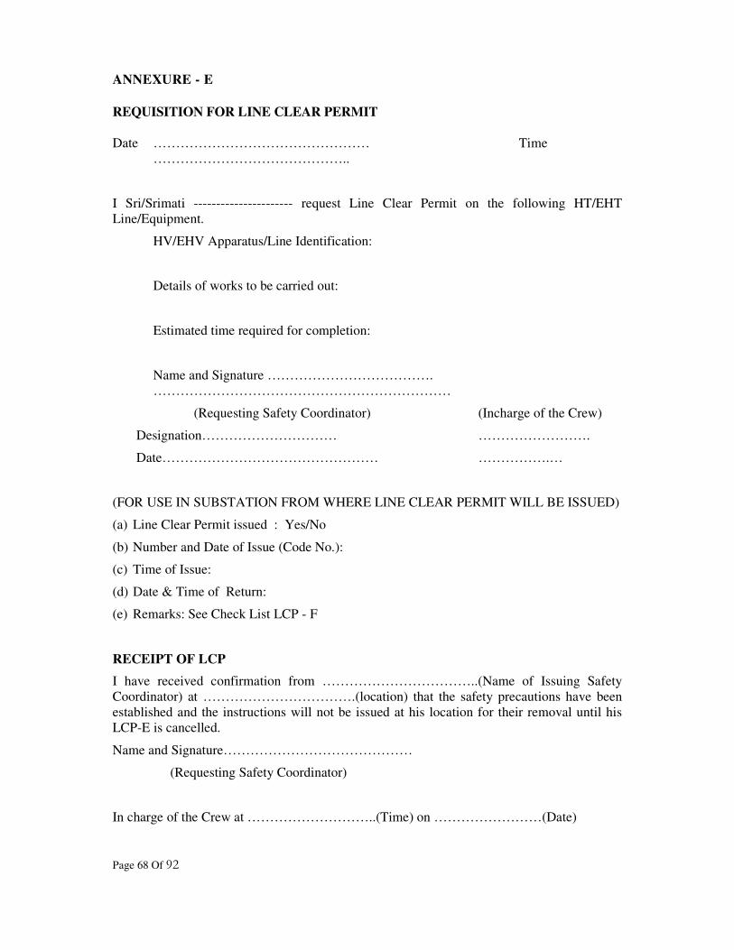
Page 68 Of 92
ANNEXURE - E
REQUISITION FOR LINE CLEAR PERMIT
Date ………………………………………… Time
……………………………………..
I Sri/Srimati ---------------------- request Line Clear Permit on the following HT/EHT
Line/Equipment.
HV/EHV Apparatus/Line Identification:
Details of works to be carried out:
Estimated time required for completion:
Name and Signature ……………………………….
…………………………………………………………
(Requesting Safety Coordinator) (Incharge of the Crew)
Designation………………………… …………………….
Date………………………………………… …………….…
(FOR USE IN SUBSTATION FROM WHERE LINE CLEAR PERMIT WILL BE ISSUED)
(a) Line Clear Permit issued : Yes/No
(b) Number and Date of Issue (Code No.):
(c) Time of Issue:
(d) Date & Time of Return:
(e) Remarks: See Check List LCP - F
RECEIPT OF LCP
I have received confirmation from ……………………………..(Name of Issuing Safety
Coordinator) at …………………………….(location) that the safety precautions have been
established and the instructions will not be issued at his location for their removal until his
LCP-E is cancelled.
Name and Signature……………………………………
(Requesting Safety Coordinator)
In charge of the Crew at ………………………..(Time) on ……………………(Date)

Page 69 Of 92
(To be printed on the reverse of LCP-E: Checklist of Line Clear Permit)
CONDITIONS:
(a) This permit is valid only for working in the Feeder/Equipment mentioned herein and not
in any other Feeder/Equipment.
(b) Only authorised persons are allowed to work on Feeders/Equipments for which the permit
has been issued.
(c) Works as per requisition only should be carried out.
(d) Before touching any part of the Feeder/Equipment the same should be Earthed at two
points on either side through standard discharge rods connected with good Earths.
Temporary Earths may only be removed after completion of all works and after all the
men have come down from the Feeder/Equipment.
(e) Work should be so planned that the Line Clear is returned before or at the time indicated.
If unavoidable delay is anticipated advance information should be given to the location
from where the Line Clear is issued.
(f) Before return of the Line Clear, it should be ensured that all the men, materials,
tools/tackles etc. on line have returned and reported that all temporary returned and
reported and all temporary earths removed. There should also be a check on the material,
Tools and Plant issued for the work to ensure that nothing is left behind on the Line or
Equipment.
(g) Only authorised persons should return Line Clear.
(h) In case the Line Clear cannot be returned in person, the same may be returned to the Line
Clear Issuing Authority over Telephone by naming the Code Words assigned and the
telephone number which is used for naming the Code Words assigned. In case two or
more different Code Words are issued to the two or more persons in whose favour the
permit is given, those persons must jointly return the Line Clear by naming their own
Code Words. The Line Clear Return will not be deemed to be accepted unless returned by
all these persons.
(i) The Line Clear issuing authority should go over the checklist of Line Clear Return before
accepting it.
(j) If Line Clear is returned over telephone, the Line Clear Return Form duly filled and
signed should be sent to the Line Clear Issuing Authority by post immediately for record.
(k) Control persons should keep all the required data of LCP issued & LCR received. He
should monitor and keep specific note in log sheet when more than one LCP are issued on
same line/ equip/bay alongwith code words.
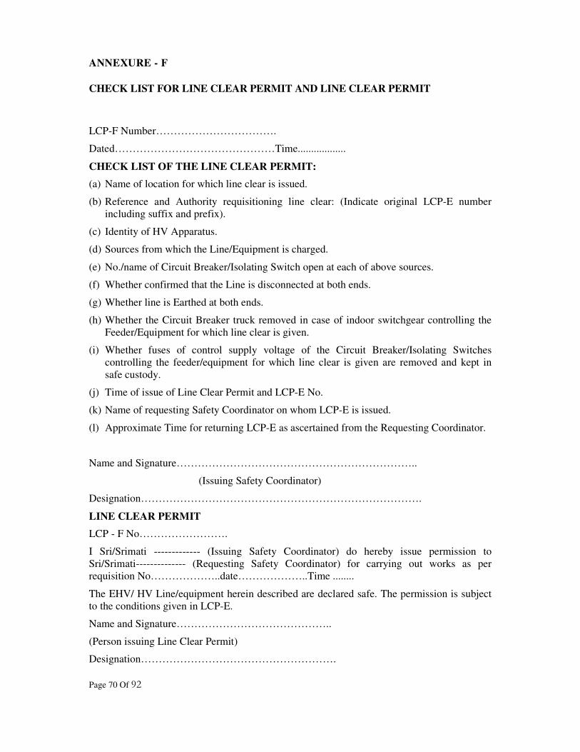
Page 70 Of 92
ANNEXURE - F
CHECK LIST FOR LINE CLEAR PERMIT AND LINE CLEAR PERMIT
LCP-F Number…………………………….
Dated………………………………………Time..................
CHECK LIST OF THE LINE CLEAR PERMIT:
(a) Name of location for which line clear is issued.
(b) Reference and Authority requisitioning line clear: (Indicate original LCP-E number
including suffix and prefix).
(c) Identity of HV Apparatus.
(d) Sources from which the Line/Equipment is charged.
(e) No./name of Circuit Breaker/Isolating Switch open at each of above sources.
(f) Whether confirmed that the Line is disconnected at both ends.
(g) Whether line is Earthed at both ends.
(h) Whether the Circuit Breaker truck removed in case of indoor switchgear controlling the
Feeder/Equipment for which line clear is given.
(i) Whether fuses of control supply voltage of the Circuit Breaker/Isolating Switches
controlling the feeder/equipment for which line clear is given are removed and kept in
safe custody.
(j) Time of issue of Line Clear Permit and LCP-E No.
(k) Name of requesting Safety Coordinator on whom LCP-E is issued.
(l) Approximate Time for returning LCP-E as ascertained from the Requesting Coordinator.
Name and Signature…………………………………………………………..
(Issuing Safety Coordinator)
Designation…………………………………………………………………….
LINE CLEAR PERMIT
LCP - F No…………………….
I Sri/Srimati ------------- (Issuing Safety Coordinator) do hereby issue permission to
Sri/Srimati-------------- (Requesting Safety Coordinator) for carrying out works as per
requisition No………………..date………………..Time ........
The EHV/ HV Line/equipment herein described are declared safe. The permission is subject
to the conditions given in LCP-E.
Name and Signature……………………………………..
(Person issuing Line Clear Permit)
Designation……………………………………………….

Page 71 Of 92
ANNEXE G
LINE CLEAR RETURN
LCP - G Number………………………………….
Date ……………………………………………….Time..............
LCP-F No……….. Dated…………….
I Sri/Srimati --------------- hereby return the LCP no -----at time ------- for the following
HT/EHT Line/Apparatus. I declare that all the crew who were sent on work have been
withdrawn, temporary earth(s) removed, all repair tools and materials checked and the
Feeders/Equipments mentioned below are safe to be energised.
(a) HV/EHV Apparatus/Line Identification:
(b) Safety Precaution no longer required:
(c) Isolation [State locations and each point of Isolation indicating means by which Isolation
was achieved.]
(d) Earthing [State location at which Earthing was established and identify each point of
Earthing means, which achieved Earthing.]
(e) Details of work done
CHECK LIST TO BE TICKED OFF:
(a) Whether all men withdrawn: Yes
(b) Whether all temporary Earth removed: Yes
(c) Whether materials, Tools and Plant used in the work have been checked: Yes
(d) Code Number (If used when Line Clear is returned over phone) -----------------
Name and Signature………………………………………….
(Requesting Safety Coordinator)
Designation……………………………………………………
Incharge of the Crew ------------------------
(Designation)
***
Page 72 Of 92
SECTION-12
COMMUNICATION AND DATA ACQUSITION
12.1 INTRODUCTION
12.1.1 This section specifies the minimum requirements of communication and data
acquisition to be provided by each User at connection Points/ Interface Points and
Cross Boundary Circuits.
12.2 OBJECTIVE:
12.2.1 The objective of this section is to define the minimum acceptable communication and
data acquisition requirements to enable STU/ Transmission Licensee to manage the
Transmission System in a safe and economic manner consistent with the requirements
of his Licence.
12.3 SUPERVISORY CONTROL AND DATA ACQUISITION (SCADA):
12.3.1 STU/Transmission Licensee shall install and make operative an operational metering
data collection system under SCADA for storage, display and processing of
operational metering data. All the Users shall make available outputs of their
respective operational meters to the SCADA interface equipment.
12.3.2 The data collection, storage and display centre shall be the State Load Despatch
Centre (SLDC).
12.4 COMMUNICATION:
12.4.1 Independent dedicated communication links for voice communications, written
communications and data acquisition shall be installed and maintained by STU/
Transmission Licensee between all the Generating Stations, receiving stations,
Substations and SLDC / ALDC. In addition similar links between adjacent
Transmission System Substations shall also be established. Other means of reliable
communication system shall also be established to ensure the safe and secure grid
operation.
12.4.2 The communication shall be available by direct dialling of discrete numbers and also
through hotline by just lifting of telephone hand set. Hotline links shall also be
established by STU between all the major Generating Stations, important Substations
and SLDC.
12.5 DATA ACQUISITION:
12.5.1 The following real time data are required by SLDC for an effective control of the
Power System:
(a) MW and MVAr Generated in each Generating Station,

Page 73 Of 92
(b) MW and MVAr Drawal from the external connection,
(c) MVAr and MVAr Hours generated or absorbed in each Generating Station,
(d) MVAr Imported or Exported from the external connections,
(e) Voltages in all the System busbars,
(f) Frequency in the System,
(g) MW & MVAr flow in each Transmission Line.
12.5.2 The Generating Companies shall provide the necessary transducers for the
transmission of the above data from their Generating Stations to SLDC/WRLDC.
12.5.3 STU/ Transmission Licensee shall similarly provide the necessary transducers for the
transmission of the above data from their receiving stations and Substations to
SLDC/WRLDC.
12.5.4 STU shall establish a suitable data transfer link between SLDC and WRLDC for
exchange of operational data transmission.
12.5.5 Mutually agreed procedures shall be drawn up between the STU/ Transmission
Licensee and other Users outlining inter responsibility, accountability and recording
of day-to-day communications and data transmission on operational matters.
12.5.6 All the additional data such as breaker/switch position shall be transmitted on "if
change" basis. Geographical Positioning Systems (GPS) may be used for time
stamping of the trip information at the respective stations.
12.5.7 At all the 400 kV Lines and important 220 kV Lines, disturbance recorders shall be
installed and the recorder data shall be made available at SLDC for post event
analysis of the disturbances.
***

Page 74 Of 92
SECTION-13
OPERATIONAL EVENT AND INCIDENT/ACCIDENT REPORTING
13.1 INTRODUCTION
13.1.1 This section covers the details of requirement for the exchange of information relating
to operations and/or events on the Total System including the Western Grid which
have or may have an operational effect on:
(a) The Gujarat Power Grid in case of an operation and/or event occurring on a User
System,
(b) A User System in the case of an operation and/or event occurring in the
Transmission System.
13.1.2 The procedure for issue of warnings in the event of a risk of serious and widespread
disturbance on the whole or part of the Gujarat State Power Grid is set out in this
Section.
13.2 OBJECTIVE:
13.2.1 The objective of this section is to define the incidents to be reported, the reporting
route to be followed and the information to be exchanged between Users to ensure a
consistent approach to the reporting of incidents and accidents on the Transmission
System. These information are required to identify the potential impact of an
operation and/or event and assess the possible risk arising from it, so that appropriate
action is taken by the concerned to maintain the integrity of the Transmission System.
The action to be taken arising from the exchange of this information depends on the
circumstances and details for each case and does not fall within the purview of this
section.
13.3 REPORTABLE INCIDENTS:
13.3.1 All events in the Transmission System having an operational effect on the User's
System shall be notified by STU/ Transmission Licensee to SLDC and the Users,
whose systems are affected.
13.3.2 All events on the User's System having an operational effect on the Transmission
System shall be notified by the User to STU/ Transmission Licensee and SLDC who
in turn shall notify the other Users on whose System the event may have an
operational effect.
13.3.3 Typical examples of reportable incidents that could affect the Transmission System
are as follows:
(a) Exceptionally high/low voltage or frequency,
(b) Serious equipment problem i.e. major circuit breaker, transformer, busbar fault,
(c) Major problem in the Generating Unit,

Page 75 Of 92
(d) Tripping of ICT, Transmission Line or Capacitor Bank,
(e) Major fire incident, cyclones, storms, earthquakes etc.
(f) Major protection failure,
(g) Over loading of Equipment or Transmission Line which may result in hazard to
the personnel,
(h) Activation of any alarm or indication of abnormal operating condition,
(i) Adverse climatic conditions being experienced or forecast,
(j) Breakdown, or faults, or temporary changes in the capabilities of Plant and/or
apparatus,
(k) Impending risks of protection operation,
(l) Loss of load,
(m) Accidents,
(n) Excessive drawal deviations,
(o) Minor equipment alarms.
The last two reportable incidents are typical examples of those of lesser
consequences, but still affect the Transmission System and can be reasonably
classified as minor. They require corrective action but do not warrant management
reporting until a later, more reasonable time.
13.3.4 The examples indicated in the above clause 13.3.3 are only illustrative and in no way
limit the general requirements to be reported.
13.4 REPORTING PROCEDURE:
13.4.1 All reportable incidents occurring in lines and equipments of 66 kV and above at the
Grid Sub-stations shall promptly be reported orally by the User whose equipment has
experienced the incident to all other significantly affected Users and SLDC. The
reporting User should submit a written confirmation to SLDC within one hour of such
oral report. If the reporting incident is of major nature, the written report may be
submitted within two hours duly followed by a comprehensive report within 48 hours
of the submission of the initial written report. In other cases, the reporting User shall
submit a report within five working days to SLDC.
13.4.2 The SLDC shall call for a report from any User on any reportable incident affecting
other Users, in case such User whose equipment might have been a source of the
reportable incident does not report the same. However this shall not relieve any User
from the obligation to report events in accordance with IE Rules, 1956 which are in
force for time being and will be replaced by the rules made under Electricity Act,
2003. The format for such a report shall be as per the approval of the Grid Code
Review Panel and typically contain the following:
(a) Location of the incident,
(b) Date and time of the incident,
(c) Plant or Equipment involved,

Page 76 Of 92
(d) Supplies interrupted and the duration wherever applicable,
(e) Amount of Generation lost, wherever applicable,
(f) System Parameters before and after the incident,
(Voltage, Frequency, Flows, Generation, etc.)
(g) Network configuration before the incident,
(h) Relay indications and performance of protection,
(i) Brief description of the incident,
(j) Estimated time of return to service,
(k) Any other relevant information,
(l) Recommendations for future improvement,
(m) Name and designation of reporting officer.
13.4.3 The report shall contain sufficient detail to describe the event to enable the recipient
to assess the implications and risks arising out of the same. The cause need not be
included in the report but the recipient may ask for clarifications wherever necessary
and it is obligatory that the reporting User shall put his best efforts and provide all the
necessary and reasonable information.
13.4.4 In case of a request by either party the oral report shall be written down by the sender
and dictated by way of a telephone message or sent by Fax/e-mail to the recipient. In
case of an emergency the report can be given only orally and followed by written
confirmation.
13.4.5 The maximum time limit allowed for oral report of the event is fifteen minutes from
the time of the occurrence of the event.
13.4.6 SLDC will be responsible for reporting event in line with the procedure set in IEGC.
13.5 SIGNIFICANT EVENTS:
13.5.1 Significant event includes such Events having an operational effect e.g.
(a) Tripping of Plant and/or Apparatus manually or automatically,
(b) Voltage outside statutory limits,
(c) System frequency outside statutory limits,
(d) System instability, or
(e) System overloads.
13.5.2 Wherever a User reports an event, which the SLDC or STU/ Transmission Licensee
considers to have had a significant effect on the Transmission System, STU/
Transmission Licensee may require the User to report that event in writing within one
day.
13.5.3 Wherever STU/ Transmission Licensee notifies SLDC and a User of any event which
the User or SLDC considers to have had a significant effect on the Users' System, the
User may require the Transmission Licensee to report that event in writing within one
day.

Page 77 Of 92
13.6 WARNINGS:
13.6.1 An oral warning shall be issued by SLDC and confirmed in writing as well, to the
STU/ Transmission Licensee and the Users, who may be affected when SLDC knows
that there is a risk of widespread and serious disturbance to the whole, or part of, the
total System.
13.6.2 Provided that sufficient time is available, the warning shall contain such information,
as the SLDC considers reasonable, to explain the nature, extent of the anticipated
disturbance, to the User and STU/ Transmission Licensee, provided that such
information is available to SLDC.
13.6.3 Each User and STU/ Transmission Licensee, on receipt of such a warning, shall take
necessary steps to warn its operational staff and maintain its Plant and Apparatus in
the condition in which it is best able to withstand the anticipated disturbance for the
duration of the warning.
13.6.4 Scheduling and Despatch may be affected during the period covered by such a
warning.
13.7 LOSS OF COMMUNICATION WITH THE SLDC:
13.7.1 In the event of loss of communication with SLDC the provision made as above shall
not apply but instead the following provision shall apply:
13.7.2 Each Generating Station shall continue to operate in accordance with the last
Despatch instruction issued by SLDC, but shall use all reasonable endeavours to
maintain the System frequency at the target of 50 Hz, plus or minus 0.5 Hz by
monitoring frequency until such time the new Despatch instructions are received from
SLDC.
13.8 MAJOR FAILURE:
13.8.1 Whenever a major failure takes place, STU/ Transmission Licensee and other Users
shall co-operate and inquire and establish the cause of such failure and produce
appropriate recommendations. STU shall submit the inquiry report to the Grid Code
Review Panel and submit the report with the recommendations of the Panel to GERC
within two months of the incident.
13.9 ACCIDENT REPORTING:
13.9.1 If any accident occurs in connection with the Generation, Transmission, Distribution
Supply or use of electricity or in connection with any part of electric lines or electrical
plant of any person and the accident results or is likely to have resulted in loss of
human or animal life or any injury to a human being or an animal, the same shall be
dealt with, in accordance with procedures laid down in the Power System Safety
Standard.
***
Page 78 Of 92
SECTION-14
DATA REGISTRATION
14.1 INTRODUCTION:
14.1.1 This section specifies a list of all the data required by STU, which is to be provided by
the Users, and the data required by the Users to be provided by STU at the required
time specified in the various Sections of the Grid Code. The corresponding Sections
of the Grid Code contain the obligation to submit the data and define the times at
which the data is to be supplied by the Users.
14.2 OBJECTIVE:
14.2.1 The objective of this section is to list all the data and the corresponding sections of the
Grid Code to be provided by the Users to STU and vice versa.
14.3 RESPONSIBILITY:
14.3.1 All the Users are responsible for submitting the up-to-date data in accordance with the
provisions of the Grid Code. All the Users shall provide STU, the names, addresses
and the telephone numbers of the persons responsible for sending the data. STU shall
inform all the Users the names, addresses and telephone numbers of the persons
responsible for receiving the data.
14.3.2 STU shall provide up-to-date data to Users as provided in the relevant Sections of the
Grid Code.
14.3.3 Responsibility for the correctness of these data rests with the concerned Users
providing the data.
14.4 LIST OF DATA TO BE REGISTERED:
14.4.1 The following data are required to be furnished by the Generating Companies to STU:
(a) Planning Data Requirements - Generation: As per Annexure A - Part I - of Section
- 4.
(b) Operation Planning Data pertaining to the Generating Stations - As per Annexure
D of Section - 6.
(c) System Data pertaining to the Generating Stations - As per Transmission Section
of Power System Management and Operation Standards.
14.4.2 The following data are required to be furnished by the Distribution Companies to
STU:
(a) Planning Data Requirements - Distribution: As per Annexe A - Part II - of Section
- 4.

Page 79 Of 92
(b) Operation Planning Data pertaining to Distribution - As per Annexe D of Section -
6.
14.4.3 The following data are required to be furnished by STU to the concerned:
(a) Planning Data Requirements - Transmission System - As per Annexe B of Section
- 4.
(b) Site Responsibility Schedule - As per Annexe C of Section - 5.
14.5 METHODS OF SUBMISSION OF DATA:
14.5.1 The data schedules are structured to serve as standard formats for data submission and
these formats shall be used for written data submission. Wherever standard data
formats are not given, these should be developed by SLDC in consultation with the
Users.
14.5.2 All the data to be submitted to STU or to such other department including any other
Transmission Licensee as STU may from time to time notify to Users. The name of
the person who submits each schedule of data shall be indicated.
14.5.3 Wherever a computer data link exists between the User and SLDC /Transmission
Licensee, data may be submitted through this link. The data shall be in the same
format as specified for paper transmission except for electronic encoding for which
some other format may be more appropriate. The User shall specify the method to be
used in consultation with STU/SLDC/Transmission Licensee and resolve issues such
as protocols, transmission speeds etc., at the time of transmission.
14.6 CHANGES IN USER'S DATA:
14.6.1 Whenever the User becomes aware of the change to any items of the data registered
under License, the User must promptly notify the STU of the changes. STU on receipt
of the changes shall promptly correct the database accordingly. This shall also apply
to any data compiled by STU regarding his own System.
14.7 DATA NOT SUPPLIED:
14.7.1 All the Users are obliged to supply the data referred to in the individual Sections of
the Grid Code and listed in clause 14.4. In case any data is missing and not supplied
by the User, STU may act reasonably. If and when necessary, he may estimate such
data depending upon the urgency of the situation. Similarly in case any data is
missing and not supplied by STU, the concerned User may, act reasonably. If and
when necessary, he may estimate such data depending upon the urgency of the
situation. Such estimates, in each case, shall be based upon the corresponding data for
similar Plant or Apparatus, or upon such other information, the User or STU, as the
case may be, deems appropriate.
14.8 SPECIAL CONSIDERATIONS:
14.8.1 STU or any User may at any time make reasonable request for extra data as necessary.
***

Page 80 Of 92
Page 81 Of 92
ATTACHMENT – 1
TRANSMISSION SYSTEM PLANNING AND SECURITY STANDARD
1.0 INTRODUCTION
1.1 The Transmission System Planning and Security Standard formulates the guidelines
for planning and expansion of Transmission System in the State of Gujarat. The scope
of this standard covers:
(a) System studies.
(b) Assessment of the system data.
(c) Assessment of generation availability.
(d) Planning criteria.
(e) Security conditions required for maintaining specified degree of reliability.
(f) Criteria for Substation planning.
(g) Estimation of reactive power compensation required.
2.0 TRANSMISSION PLANNING
2.1 The long and short term perspective planning involves an integrated approach for
evacuating power from different Generating Stations, irrespective of their ownership,
and delivering it to the beneficiaries over an optimally designed Transmission System
with reliability, security and economy. The power system in Gujarat has to be planned
in such a manner, that the power received from all the Generating Stations, the share
of power from Western grid and central sector Generating Stations can be transmitted
without constraints to different beneficiaries, as per their allocated shares, maintaining
a reasonably good voltage profile, stability conditions and redundancy criteria.
2.2 The transmission planning should be developed to achieve a strong co-ordinated
power system for the Western region and ultimately a national grid, where substantial
inter-regional transfers can be achieved with optimised utilisation of available
generation. The transmission planning shall also provide a high standard of supply to
beneficiaries with acceptable degree of reliability and at reasonable cost. The criterion
should be that even under the conditions of the specified outages considered in the
security standards, the power flow should not be affected. The transmission planning
should keep in view the long term future load growth also and the Transmission Lines
and Substations shall be so planned that the same can be upgraded when necessary in
future, with minimum interruptions and modifications.
2.3 For the purpose of reducing inventory, procurement time and installation time, the
Licensee shall adopt standardised designs as far as possible for transmission line
towers, structures for substations, substation lighting, control room lighting and
ventilation, substation earthing, standardised specification for line materials,
Page 82 Of 92
transformers, substation equipment, cables, bus bar accessories, insulators, hard
wares, lightening arrestors etc.
2.4 The possibility of providing adequate transmission connections within the Gujarat
state grid as well as between interstate grids has to be considered wherever
economically feasible considering all economic energy/capacity interchanges subject
to trade off between new generation and cost of transmission. The modern Flexible
AC Transmission System (FACTS) based on thyristor based controls, HVDC, fast
controllable phase shifters etc., have also to be considered wherever economically
feasible and/or constraints of corridor exist for construction of new Transmission
Lines.
3.0 SYSTEM STUDIES
3.1 The loads to be supplied from various Substations at steady state within the limits of
declared voltage and acceptable frequency of 50 Hz and the future load development
has to be assessed after making a detailed study of the present conditions and a load
survey. A reasonable estimate of transmission losses shall also be included to arrive at
peak generation capacity. The system is to be further evolved based on the following
power system studies:
(a) Load flow
(b) Optimal power flow for various conditions.
(c) Short Circuit
(d) System stability- Steady state
(e) System stability-transient
(f) Studies to determine switching/temporary over voltages
(g) Other studies as required.
3.2 These studies require suitable computer programs. Mathematical models of
generation, transmission and load shall be prepared separately for each year of a plan
period assessing probable year of commissioning of particular lines, sub-stations,
additional transformers in existing sub-stations etc, based on the system network for
the year in question with all the generation and load buses properly located. Inter
connections with the western grid through neighbouring states at 400kV and 220kV
levels shall have to be incorporated. Appropriate equivalent circuit models shall be
used to take into account the fault level at the Connection Points/ Interface Points.
The interconnection buses shall be modelled by representing significant and necessary
portions of the neighbouring networks to represent realistically the MW and MVA
imports/exports. Studies shall be carried out both for peak load and minimum load
conditions.
4.0 SYSTEM DATA
4.1 To arrive at a reasonably accurate load forecast and for conducting studies,
compilation and updating of system data is absolutely necessary. The planning study
should begin with the proper representation of the existing system to establish the
base case and to validate the model. The results obtained for the existing system
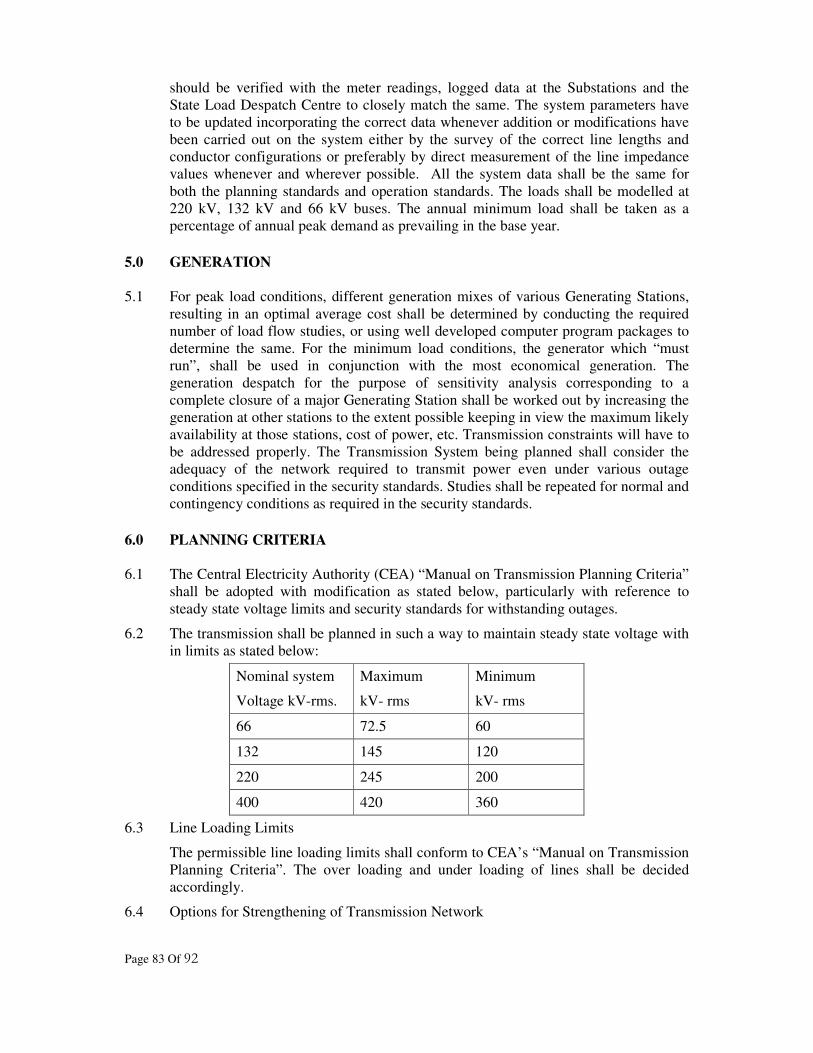
Page 83 Of 92
should be verified with the meter readings, logged data at the Substations and the
State Load Despatch Centre to closely match the same. The system parameters have
to be updated incorporating the correct data whenever addition or modifications have
been carried out on the system either by the survey of the correct line lengths and
conductor configurations or preferably by direct measurement of the line impedance
values whenever and wherever possible. All the system data shall be the same for
both the planning standards and operation standards. The loads shall be modelled at
220 kV, 132 kV and 66 kV buses. The annual minimum load shall be taken as a
percentage of annual peak demand as prevailing in the base year.
5.0 GENERATION
5.1 For peak load conditions, different generation mixes of various Generating Stations,
resulting in an optimal average cost shall be determined by conducting the required
number of load flow studies, or using well developed computer program packages to
determine the same. For the minimum load conditions, the generator which “must
run”, shall be used in conjunction with the most economical generation. The
generation despatch for the purpose of sensitivity analysis corresponding to a
complete closure of a major Generating Station shall be worked out by increasing the
generation at other stations to the extent possible keeping in view the maximum likely
availability at those stations, cost of power, etc. Transmission constraints will have to
be addressed properly. The Transmission System being planned shall consider the
adequacy of the network required to transmit power even under various outage
conditions specified in the security standards. Studies shall be repeated for normal and
contingency conditions as required in the security standards.
6.0 PLANNING CRITERIA
6.1 The Central Electricity Authority (CEA) “Manual on Transmission Planning Criteria”
shall be adopted with modification as stated below, particularly with reference to
steady state voltage limits and security standards for withstanding outages.
6.2 The transmission shall be planned in such a way to maintain steady state voltage with
in limits as stated below:
Nominal system
Voltage kV-rms.
Maximum
kV- rms
Minimum
kV- rms
66 72.5 60
132 145 120
220 245 200
400 420 360
6.3 Line Loading Limits
The permissible line loading limits shall conform to CEA’s “Manual on Transmission
Planning Criteria”. The over loading and under loading of lines shall be decided
accordingly.
6.4 Options for Strengthening of Transmission Network

Page 84 Of 92
(a) Addition of new Transmission lines to avoid over loading of existing system
(wherever three or more circuits of the same voltage class are envisaged between
two Substations, the next higher transmission voltage may be considered).
(b) Upgradation of the existing Transmission Lines such as raising height of
conductor supports and / or switch over to insulated cross-arms to facilitate
change over to higher voltage, if the tower design so permits.
(c) Reconductoring of the existing transmission line with higher size of conductors or
with AAAC (All Aluminium Alloy Conductor)
(d) The choice shall be based on cost, reliability, right of way requirements, energy
losses, down time, etc.
6.5 All single circuit lines shall be planned with double circuit towers, wherever
technically feasible, to enable future expansion without right of way problems.
7.0 SECURITY STANDARDS
7.1 Steady State Stability
The system shall be planned to withstand satisfactorily without any load shedding or
altering the generation at Generating Stations for at least, any one of the following
outage conditions:
(a) Outage of any tower in a D/C Transmission Line
(b) Two circuits of 66 kV or 132 kV or 220 kV lines.
(c) One circuit of 400 kV line.
(d) One Interconnecting Transformer.
(e) One largest capacity generator.
(f) One inter-connecting line with neighbouring grid.
The above contingencies shall be considered assuming a pre-contingency system
depletion (planned outage) of another 220 kV double circuit line or 400 kV single
circuit line in another corridor and not emanating from the same Substation. All the
Generating Stations shall operate within the limits as per their reactive capability
curves and the network voltage profile shall also be maintained within the specified
voltage limits.
7.2 Transient Stability
The system shall be designed to maintain synchronism and system integrity under the
following disturbances.
(a) Outage of the largest size generator in the Western grid or connection with
neighbouring grids.
(b) (i) A single line to ground fault on a 400 kV line, single pole opening of the
faulted phase (5 cycles) with unsuccessful reclosure (dead time 1 sec) followed by
3 pole opening (5 cycles) of the faulted line.
(ii) 400 kV D/C line:

Page 85 Of 92
(A) When both the circuits are in operation, the system shall be capable of
withstanding a permanent fault on one of the circuits followed by a three-pole
opening (100-m sec.) of the faulted circuit.
(B) When one of the circuits is under maintenance / outage the system shall
be capable of withstanding a transient fault on the circuit in service.
(c) A permanent 3-phase fault with duration of 8-cycles on 220 kV or 132 kV or 66
kV line assuming three-pole opening.
(d) No stability studies for faults are required for radial lines.
8.0 SUBSTATION PLANNING CRITERIA
8.1 For meeting a particular quantum of load, the number of required Substations depends
upon the choice of voltage levels, the MVA capacity and the number of feeders
permissible etc. The number of EHT transformers, Interconnecting Transformers
shall also be considered in planning to take care of contingencies of planned/forced
outages. The rupturing capacity of the circuit breakers shall have 20 percent margin to
take care of increase in short circuit levels as the system grows. The following criteria
can be adopted:
(a) The capacity of any single substation at different voltage levels shall not normally
exceed:
400 kV 1000MVA
220 kV 320 MVA
132 kV 150 MVA
66 kV 80 MVA
(b) Size and number of Interconnecting Transformers (ICTs) shall be planned in such
a way that the outage of any single unit would not overload the remaining ICTs or
the underlying system.
(c) Size and number of HT / EHT transformers shall be planned in such a way that in
the event of outage of any single unit, the remaining HT / EHT transformers
would still supply 80% of the load. This has to be achieved in such a way that,
with the connection of the adjacent Substations, the load exceeding the capacity of
the available transformers may be transferred on to them.
(d) The rated rupturing capacity of the circuit breakers in any Substation shall not be
less than 120% of the maximum fault levels at the substations. (The 20% margin
is intended to take care of increase in short circuit levels as the system grows).
The minimum rated rupturing of capacity and duration of switchgear at different
voltage levels are as follows:
66 kV 25 kA for 1 or 3 sec*
132 kV 31.5 kA for 1 or 3 sec*
220 kV 40 kA for 1 or 3 sec*

Page 86 Of 92
400 kV 40 kA for 1 or 3 sec*
* - 1 or 3 sec. Duration may be decided as per fault level.
9.0 REACTIVE COMPENSATION
9.1 Shunt Capacitors
Shunt capacitor shall be installed at 22 kV and 11 kV preferably at load centres. In
case it is not possible at load centre, then reactive compensation shall be provided in
66/132 kV systems with a view to meet the reactive power requirement of load close
to the load points.
9.2 Shunt Reactors
Switchable shunt reactors shall be provided at 400 kV sub-stations for controlling
voltages within the limits specified. The step changes shall not cause a voltage
variation exceeding 5%. Suitable Line Reactors (Switchable/Fixed) shall be provided
to enable charging of 400 kV lines without exceeding voltage limits specified.
The line reactors shall be installed for long line at high voltage level for curtailing
switching over voltage and limiting the fault currents.
***

Page 87 Of 92
ATTACHMENT – 2
METERING AND PROTECTION STANDARDS
1.0 INTRODUCTION
1.1 This standard provide guidelines for the following:
(a) Minimum requirement of metering for commercial and operational purposes to
be provided by the User at Connection Points/ Interface Points including
Generating Stations, Switching Stations, Substations and also Cross Boundary
Circuits.
(b) Minimum requirement of protection to be provided to safeguard the system from
faults which may occur.
2.0 METERING REQUIREMENTS:
2 Generating Station Operational Metering:
2.1 The Generating Companies shall install operational metering to the Licensees'
specifications so as to provide operational information for both real time and
recording purposes to SLDC in relation to each Generating Unit at each Generating
Station in respect of the following:
(a) Bus voltage
(b) Frequency
(c) MW
(d) MVAr
(e) Any other data agreed to between the Licensee and the Generating Company
2.2 All the Instrument Transformers used in conjunction with the operational metering
shall be of accuracy class 0.2 except where already existing CT/PT which are of 0.5
class, which may continue to be used. These shall be of suitable rating to meet the
burden of lead wires and meters and shall conform to the relevant IEC or IS
specifications.
2.3 All the meters shall be calibrated to achieve the overall accuracy of Operational
Metering in accordance with the limits agreed to between the Transmission
Licensee/Distribution Licensee and the Generating Company. Records of calibration
shall be maintained for reference and shall be made available to the Licensee, upon
request. Joint site testing shall be carried out at least once in six months.
3.0 TRANSMISSION SYSTEM OPERATIONAL METERING
3.1 The Transmission Licensee shall install Operational Metering for both real time and
recording purposes at each substation as follows:
(a) For Station Busbars:
(i) Bus Voltage.

Page 88 Of 92
(ii) Frequency.
(b) For Outgoing/Incoming Lines, Power Transformers, Auxiliary Transformers and
Compensating Devices:
(i) MW.
(ii) MVAr.
(iii)Power Factor.
(iv) Current
4.0 SUPERVISORY CONTROL AND DATA ACQUISITION (SCADA)
4.1 The Transmission Licensee shall install and make operative an Operational Metering
Data Collection System under SCADA for storage, display and processing of
Operational Metering Data. All Users shall make available outputs of their respective
Operational Meters to the SCADA interface equipment.
4.2 The data collection, storage and display centre shall be the State Load Despatch
Centre (SLDC).
5.0 TARIFF METERING
5.1 The Generating Companies, CPP, the Transmission Licensees and the Distribution
Licensees and EHV Consumers who intend to use open access provisions would need
to install the meters suitable for Availability Based Tariff (ABT) at inter-utility
exchange points which would record the parameters as mentioned under Clause 5.8
5.2 The Auxiliary transformers in generating stations shall be provided with the following
meters:
(a) MW
(b) Current
(c) Voltage
(d) Active
(e) Energy
5.3 Each metering point associated with determination of energy exported or imported,
between the Generating Companies, Transmission Licensees and Distribution
Licensees shall be provided with both main and check meters on separate core of CT,
PT. The minimum standard of accuracy for these meters shall be Accuracy class 0.2.
If present metering system needs upgradation to class 0.2 it shall be completed within
6 months from effective date of this code.
5.4 All the Instrument Transformers used in conjunction with commercial (tariff)
metering shall also be of accuracy class 0.2 except where already existing CT/PT
which are of 0.5 class, which may continue to be used. These shall conform to the
relevant IEC or IS specifications. The rating shall take into account the burdens
imposed by lead wires and metering.
5.5 Data shall be collected from both the main and check metering schemes.
Page 89 Of 92
5.6 Voltage failure relays shall be provided to initiate alarm on loss of one or more phases
of the voltage supply to the meter.
5.7 All the meters shall be tested and calibrated at least once in one year using
substandard meters for this purpose. The standard meters shall be calibrated and
sealed at Govt. Authorized Meter Testing House/Laboratory once in every year.
Record of testing and calibration of substandard meters shall be maintained by the
Transmission Licensee according to the guidelines provided in the relevant IEC/IS
specifications. Records of these calibrations and tests shall be maintained for
reference.
5.8 In case of Inter State Transmission Lines, meters suitable for Availability Based
Tariff shall be provided having the following parameters
(a) Net Active Energy import/ export for each 15 minute time block of the day.
(b) Net Reactive energy import/ export for the day above 103% of voltage.
(c) Net reactive energy export/ import when voltage is below 97%.
(d) Cumulative active energy export/ import.
(e) Average frequency for each 15 minute time block of the day.
(f) Provision of storage of data in non-volatile memory for atleast 10 days.
5.9 The Generating Companies, Transmission Licensees and Distribution Licensees shall
formulate a procedure covering summation, collection and processing of tariff meter
readings at various connection sites in their areas. Whenever necessary, these
procedures can be revised.
5.10 The ownership, responsibility of maintenance and testing of these meters shall be as
mutually agreed to between the Users and the Licensees.
PROTECTION REQUIREMENTS
6.0 GENERAL PRINCIPLES
6.1 No item of electrical equipment shall be allowed to remain connected to the system
unless it is covered by the appropriate protection aimed at reliability, selectivity,
speed and sensitivity. The guidelines mentioned in the "Manual on protection of
Generators, Generator Transformers, and 220 kV and 400 kV networks" vide
publication no 274 of C.B.I.P shall be kept in view. All the Generating Companies
and the Distribution Licensees shall co-operate with the Transmission Licensee to
ensure correct and appropriate settings of protection to achieve effective,
discriminatory isolation of faulty line/equipment within the target clearance times
specified elsewhere in this Standard.
6.2 Protection settings shall not be altered, or protection bypassed and/or disconnected
without consultation and agreement of all affected Users. In case the protection has
been bypassed and/or disconnected by agreement due to any cause, the same should
be rectified and protection restored to normal condition as quickly as possible. If
agreement has not been reached, the electrical equipments shall be isolated forthwith.

Page 90 Of 92
7.0 PROTECTION COORDINATION
7.1 The settings of protective relays starting from the Generating Unit up to the remote
end of 66 kV / 33 kV and 11 kV lines shall be such that only the faulty section is
isolated under all circumstances. The Transmission Licensee shall notify the initial
settings and any subsequent changes to the Users from time to time. Routine checks
on the performance of the protective relays shall be conducted and any malfunction
shall be noted and corrected as soon as possible. The Transmission Licensee shall
conduct the required studies for deciding the relay settings, with the data collected
from the Users. Representatives of the Generating Companies, Transmission
Licensees and Distribution Licensees shall meet periodically to discuss such
malfunctions, changes in the system configuration, if any, and possible revised
settings of relays.
7.2 The Transmission Licensee shall be responsible for arranging periodical meetings
between the Generating Companies and the Distribution Licensees to discuss
coordination of protection. The Transmission Licensee shall investigate any
malfunction of protection or other unsatisfactory protection issues. The concerned
Licensees shall take prompt action to correct any protection malfunction or issue as
discussed and agreed to in these periodical meetings.
8.0 FAULT CLEARANCE TIME
8.1 From stability considerations, the maximum Fault Clearance Time for faults on any
User's system directly connected to the Transmission System, or any faults on the
Transmission System itself, shall be as follows:
Voltage Class Target clearance time
400 kV 100 m sec.
220 kV 120 m sec.
132 kV 160 m sec.
66 kV 300 m sec.
8.2 Lesser fault clearance time than the above are preferable.
8.3 Lower Fault Clearance Times for faults on a User's system may be agreed to, but only
if, in the opinion of the Transmission Licensee, system conditions allow the same. At
the Generating Stations, Line Faults should be cleared at the Generating Station end,
within the critical time, to keep the Generators in Synchronism.
9.0 GENERATOR REQUIREMENTS
9.1 All Generating Units and all associated electrical equipment of the Generating
Company connected to the Transmission System shall be protected by adequate
protection, as per CBIP manual vide publication 274, so that the Transmission System
does not suffer due to any disturbances originating at the Generating Unit.

Page 91 Of 92
10.0 TRANSMISSION LINE REQUIREMENTS
Every EHT line taking off from a Generating Station or a Substation or a switching
station shall necessarily have distance protection along with other protections as
follows:
(a) 400 kV lines: - These lines shall have two main distance protections viz., Main I
and Main II with permissive inter trip for remote earth fault. Three zone
static/numerical non-switched distance protection with permissive inter trip for
accelerated tripping at remote end in case of zone 2 fault as Main I protection shall
be provided. Main II protection shall be similar fast protection using direction
comparison or phase comparison carrier relay scheme. In addition to the above,
single pole tripping and single shot single pole auto reclosing after an adjustable
dead time shall be provided. In addition to the above backup protection with OCR
and EFR shall be provided.
(b) 220 kV lines: - Three zone static/numerical non-switched distance protection, with
permissible Intertrip for end zone fault as main protection in case of zone 2 fault
shall be provided. The backup shall be three-phase directional over current relay
and earth fault relay protection. Three pole tripping and Single Shot Three Pole
Auto-reclosing with adjustable dead time shall be provided for the stability of the
power system. However, for short 220 kV lines directional comparison or phase
comparison carrier protection as Main II can be provided. In addition to the above
backup protection with directional OCR (Over current Relay) and directional EFR
(Earth Fault Relay) shall be provided.
(c) 132 kV kV lines: - Three zone static/numerical switched protection with
permissible inter trip for accelerated tripping at remote end in case of zone 2
protection shall be provided as main protection. The backup will be directional
three-phase over current and earth fault protection.
(d) Busbar Protection: - Adequate busbar protection for the Station Busbar sections in
all 400 kV and 220 kV class substations shall be provided.
(e) Local Breaker Backup Protection (LBB): - In the event of any circuit breaker
failing to trip on receipt of trip command from protective relays, all circuit
breakers connected to the bus section to which the faulty circuit breaker is
connected are required to be tripped with minimum possible delay through LBB
protection. This protection also provides coverage for faults between the circuit
breaker and the current Transformer, which are not covered by other protections.
All 220 kV and 400 kV circuits shall have Local Breaker Backup Protection.
(f) 400 kV class Power Transformers: - These shall be provided with differential
protection, restricted earth fault protection, Bucholtz protection, and winding
temperature protection along with backup directional HV & LV IDMT over
current protection.
(g) 220 kV, 132 kV and 66 kV class Power Transformers: -These shall have
differential protection, restricted earth fault protection, Bucholtz protection, and
winding/oil temperature protection. They shall also have directional over current
as backup protection with an instantaneous element. In addition to the above, Over
Fluxing Relays, Pressure Relief valves/diaphragms shall be provided for all the
power transformers. Appropriate fire protection for all the power transformers as
Page 92 Of 92
per CBIP specifications and tariff advisory committee recommendations shall be
provided. Over fluxing relays shall be provided on transformers having rating
more than 100 MVA.
(h) Distribution System: -For smaller transformers of HV class on Distribution
System, differential protection shall be provided for 8 MVA capacity and above
along with backup time lag over current and earth fault protection with directional
feature for parallel operation. Transformers of 1.6 MVA capacity and above but
less than 8 MVA shall be protected by time lag over current, earth fault and
instantaneous restricted earth fault relays. In addition, all Transformers of 1.6
MVA and above shall be provided with gas operated relays, winding and oil
temperature protection.
(i) Distribution Lines: - All the 33kV, 22 kV and 11 kV lines at Connection Points/
Interface Points shall be provided with a minimum of over current and earth fault
relays as follows:
(i) Plain Radial Feeders: Directional over current and earth fault relays with
suitable settings to obtain discrimination between adjacent relay settings.
(ii) Parallel/Ring Feeders: Directional time lag over current and earth fault relay.
(j) Inadvertent Flow: - When two systems are operating in parallel with floating tie-
line, it may not be possible to have tie line absolutely floating because of
dynamics of network parameters and there will be a flow of energy from one
system to another system. Such inadvertent flow shall be accounted for the
purpose of commercial billing.
***
Ahmedabad G.D.VYAS
25th
August, 2004 SECRETARY