guidelines for utilizing incorsincors.in.gov/ispls convention 2013-incors.pdf · • cmr, cmr+,...
TRANSCRIPT
Guidelines for Utilizing InCORS’INDIANA’S STATEWIDE
GNSS-GPS REAL TIME NETWORKPresented byPresented by
Andrew “Dee” Baxter, PLS & Eric Banschbach, PLSLand & Aerial Survey Office
2013 ISPLS C ti2013 ISPLS ConventionJanuary 18, 2013
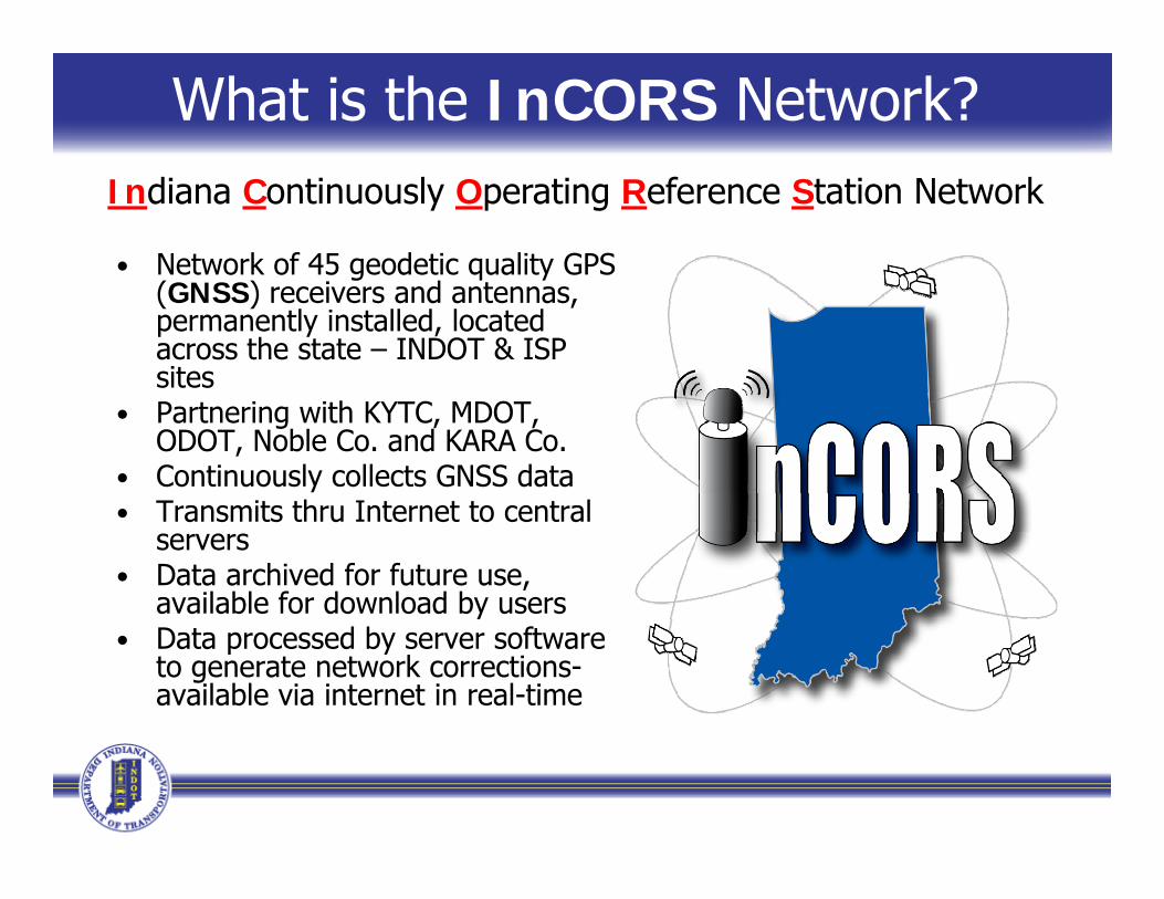
What is the InCORS Network?Indiana Continuously Operating Reference Station Network
• Network of 45 geodetic quality GPS g q y(GNSS) receivers and antennas, permanently installed, located across the state – INDOT & ISP sites
• Partnering with KYTC, MDOT, ODOT, Noble Co. and KARA Co.
• Continuously collects GNSS dataTransmits thru Internet to central• Transmits thru Internet to central servers
• Data archived for future use, available for download by users
• Data processed by server software to generate network corrections-available via internet in real-time
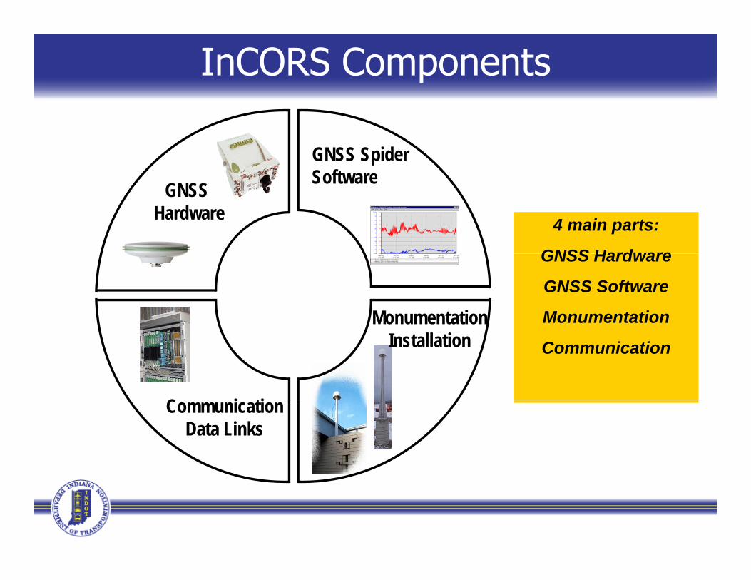
InCORS Components
GNSS SpiderSoftware
4 main parts:
GNSS Hardware
SoftwareGNSSHardware
GNSS Hardware
GNSS Software
MonumentationMonumentationCommunication
C i ti
Installation
CommunicationData Links
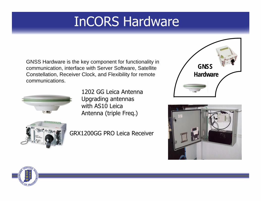
InCORS Hardware
GNSS Hardware is the key component for functionality inGNSS
Hardware
GNSS Hardware is the key component for functionality in communication, interface with Server Software, Satellite Constellation, Receiver Clock, and Flexibility for remote communications.
1202 GG Leica AntennaUpgrading antennas with AS10 Leica Antenna (triple Freq )Antenna (triple Freq.)
GRX1200GG PRO Leica Receiver

•Leica SpiderNet
InCORS Software
GNSS SpiderS ft
•Leica SpiderNet•Modular and fully scalable•For single and multiple stations SoftwareFor single and multiple stations
•INDOT 45 stations•KYTC, MDOT, ODOT & Noble Co. , ,13 stations•Plans for using 2 in Illinois for total of 60 station licenses we currently havestation licenses we currently have
•For small and large networks•For Post-Processed and RTK Networks•For all types of GPS receivers
•Leica, Trimble, Ashtech, Topcon….•For all communication methods
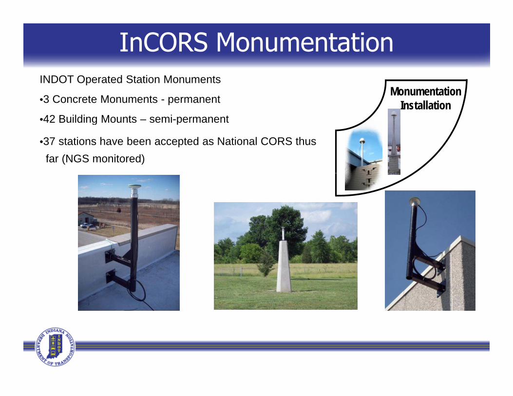
InCORS Monumentation
MonumentationInstallation
INDOT Operated Station Monuments
•3 Concrete Monuments - permanent
•42 Building Mounts – semi-permanentg p
•37 stations have been accepted as National CORS thusfar (NGS monitored)
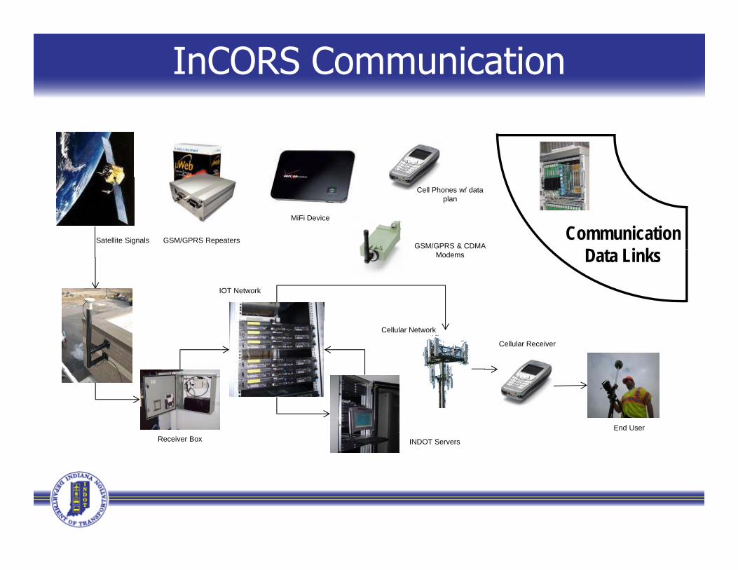
InCORS Communication
CommunicationD t Li k
GSM/GPRS Repeaters
Cell Phones w/ data plan
GSM/GPRS & CDMA
MiFi Device
Satellite Signals
Data LinksModems
AntennaIOT Network
Cellular Network
Cellular Receiver
Receiver Box INDOT Servers
End User
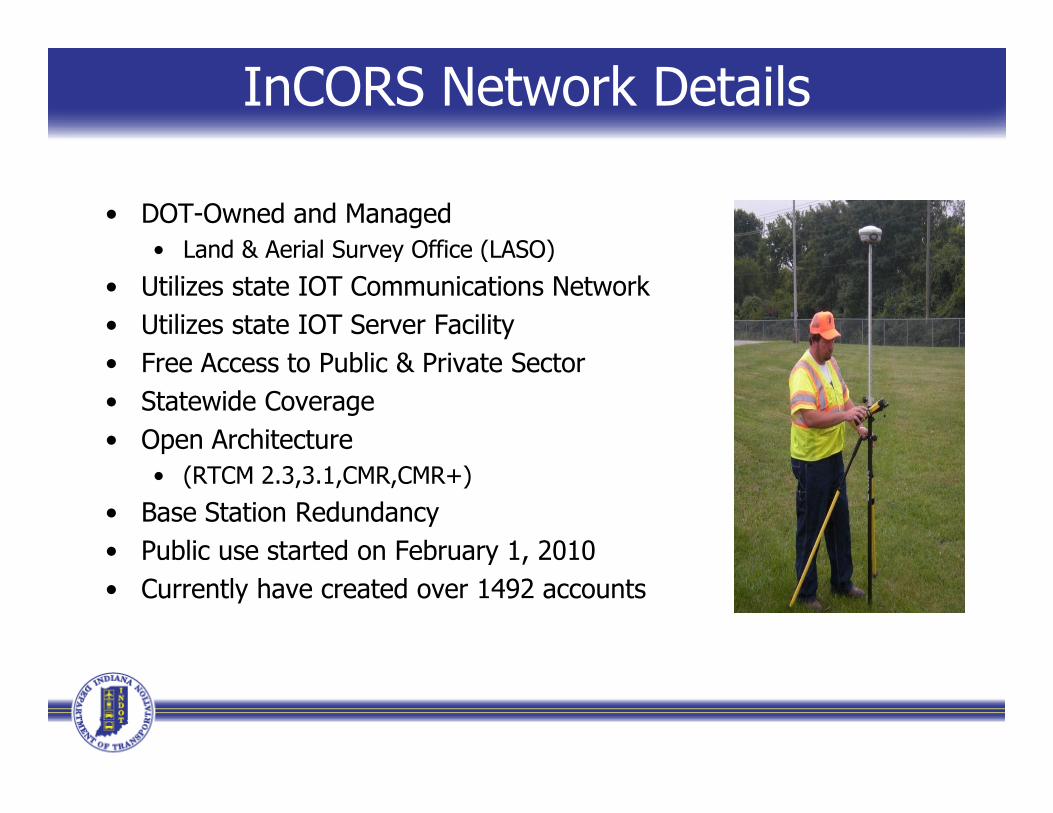
InCORS Network Details
• DOT-Owned and Managed• Land & Aerial Survey Office (LASO)• Land & Aerial Survey Office (LASO)
• Utilizes state IOT Communications Network• Utilizes state IOT Server Facility
F A t P bli & P i t S t• Free Access to Public & Private Sector• Statewide Coverage• Open Architecture
• (RTCM 2.3,3.1,CMR,CMR+)
• Base Station Redundancy• Public use started on February 1, 2010y ,• Currently have created over 1492 accounts
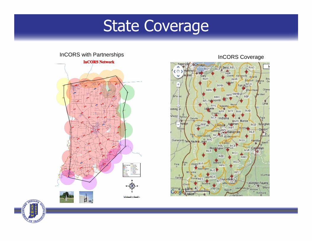
State Coverage
InCORS with Partnerships InCORS Coverage
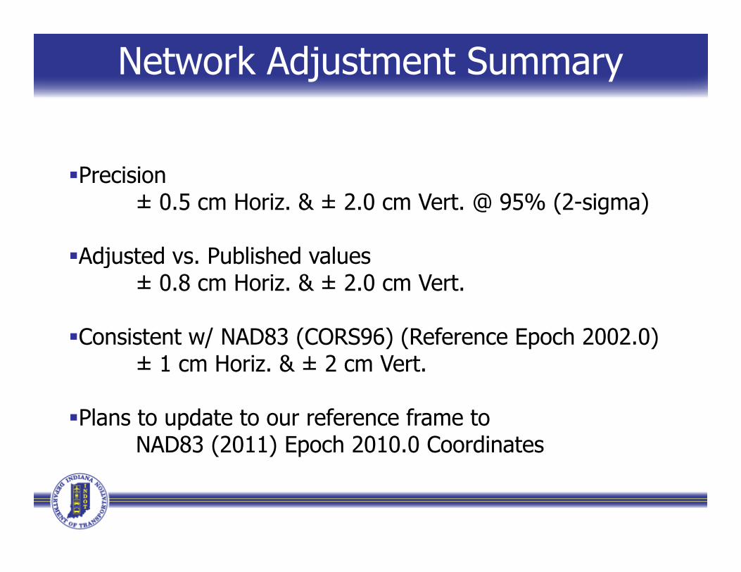
Network Adjustment Summary
PrecisionPrecision± 0.5 cm Horiz. & ± 2.0 cm Vert. @ 95% (2-sigma)
Adj t d P bli h d lAdjusted vs. Published values± 0.8 cm Horiz. & ± 2.0 cm Vert.
Consistent w/ NAD83 (CORS96) (Reference Epoch 2002.0)± 1 cm Horiz. & ± 2 cm Vert.
Plans to update to our reference frame to NAD83 (2011) Epoch 2010.0 Coordinates
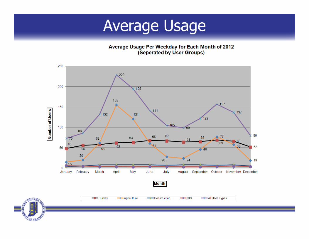
Average Usage

User Growth Over Time
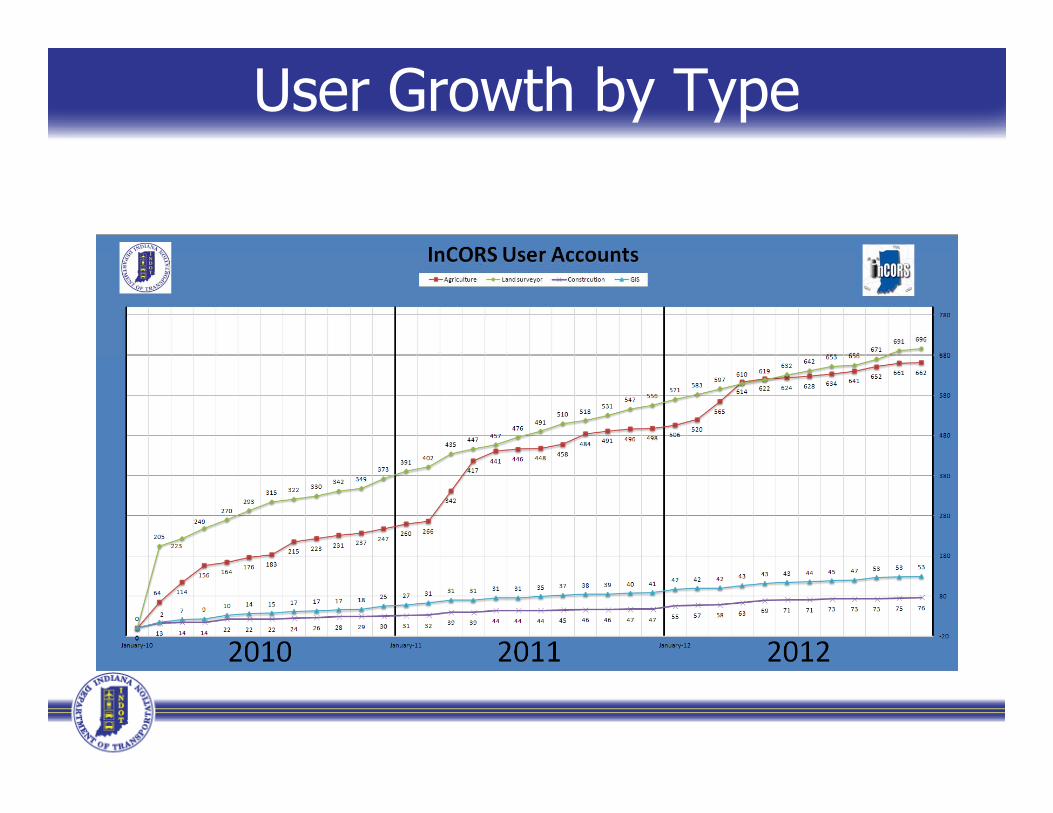
User Growth by Type

(htt // l i d t i )(htt // l i d t i )
Land and Aerial Survey Office Website(http://www.laso.indot.in.gov)(http://www.laso.indot.in.gov)
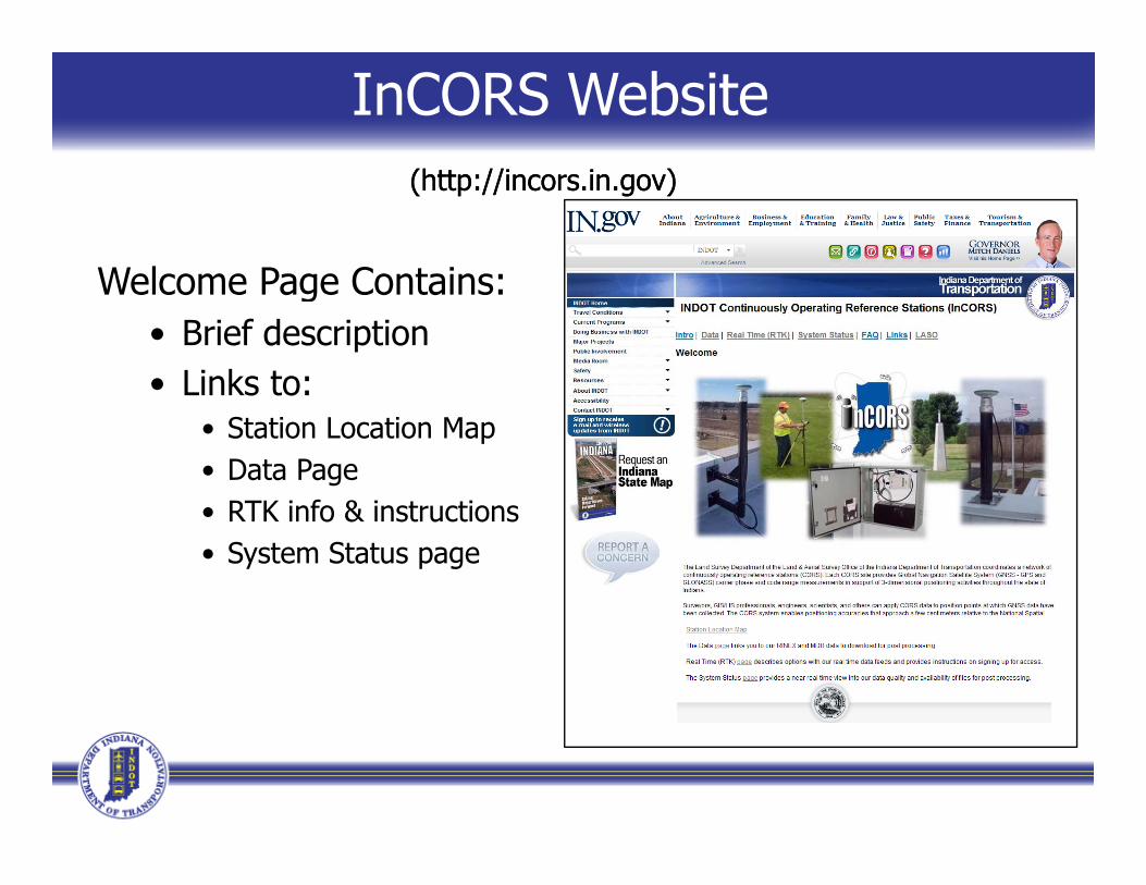
InCORS Website(http://incors.in.gov)(http://incors.in.gov)
Welcome Page Contains:Welcome Page Contains:• Brief description• Links to:• Links to:
• Station Location Map• Data Page• RTK info & instructions• System Status page
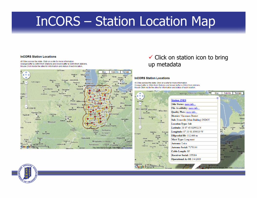
InCORS – Station Location Map
Click on station icon to bring up metadata
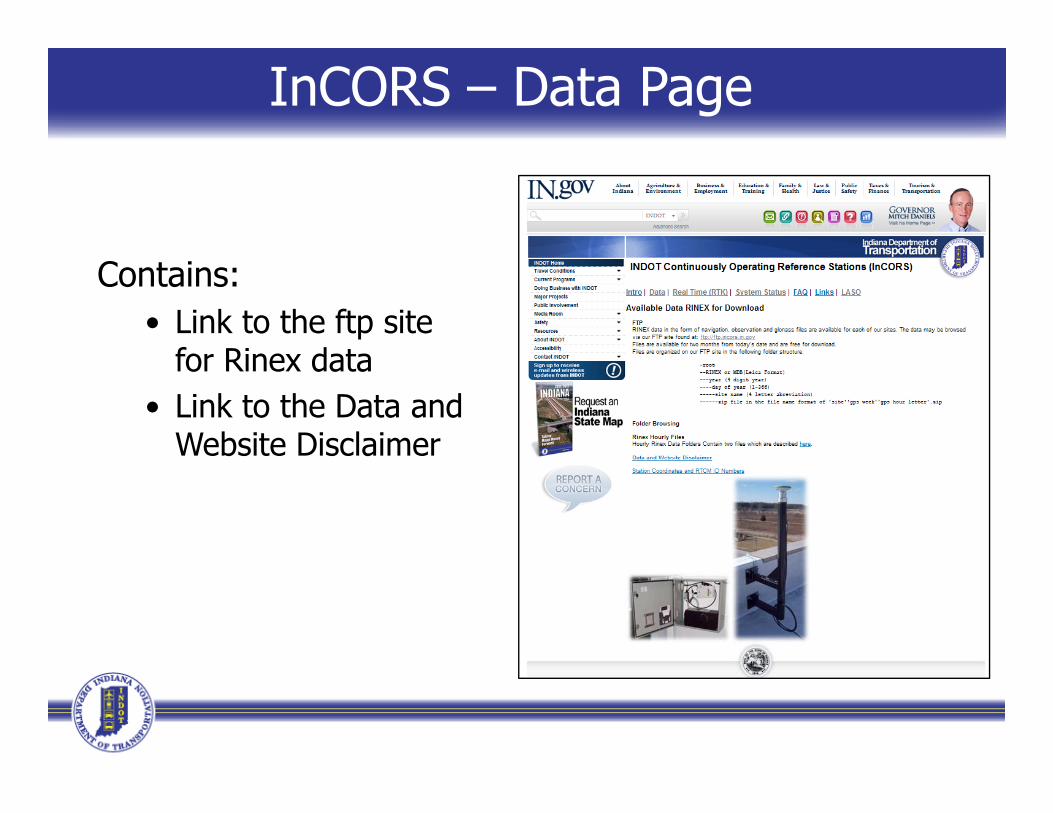
InCORS – Data Page
Contains:• Link to the ftp site
for Rinex datafor Rinex data• Link to the Data and
Website Disclaimer
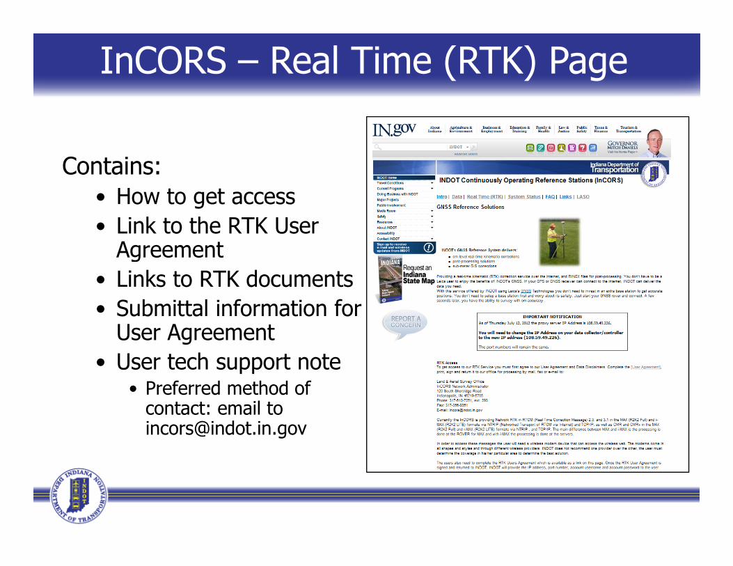
InCORS – Real Time (RTK) Page
Contains:• How to get access• Link to the RTK User
AgreementAgreement• Links to RTK documents• Submittal information for
User Agreement• User tech support note
• Preferred method of• Preferred method of contact: email to [email protected]
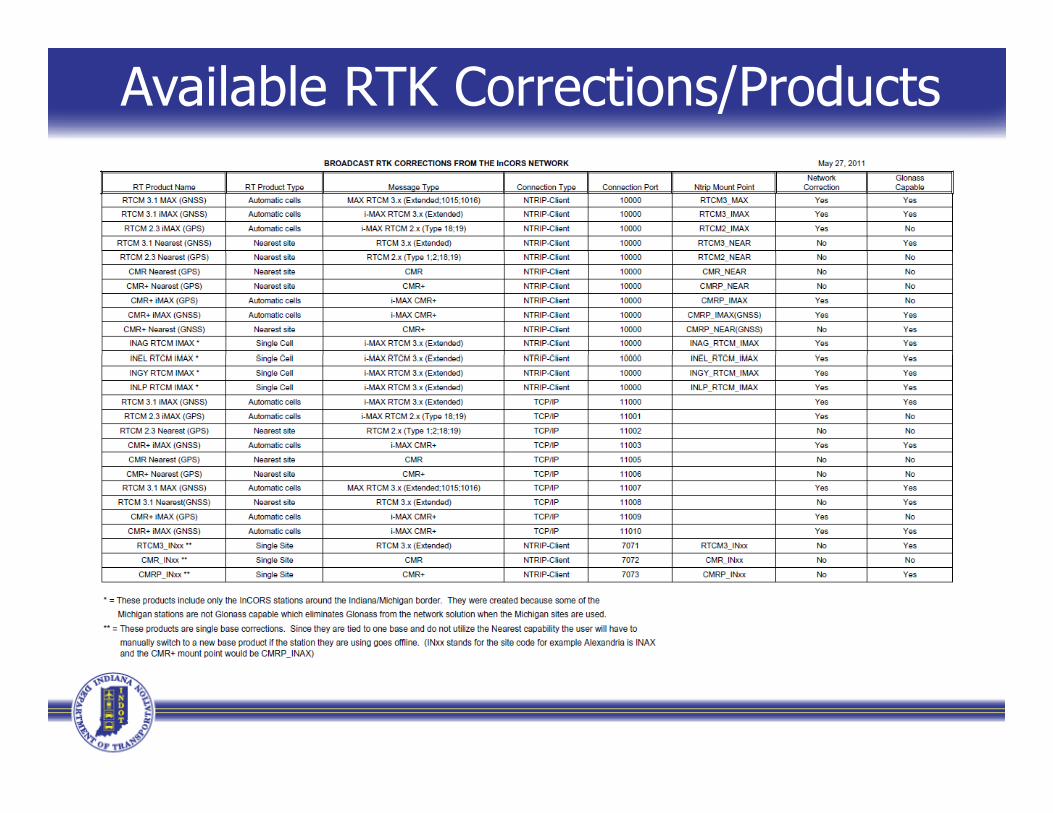
Available RTK Corrections/Products
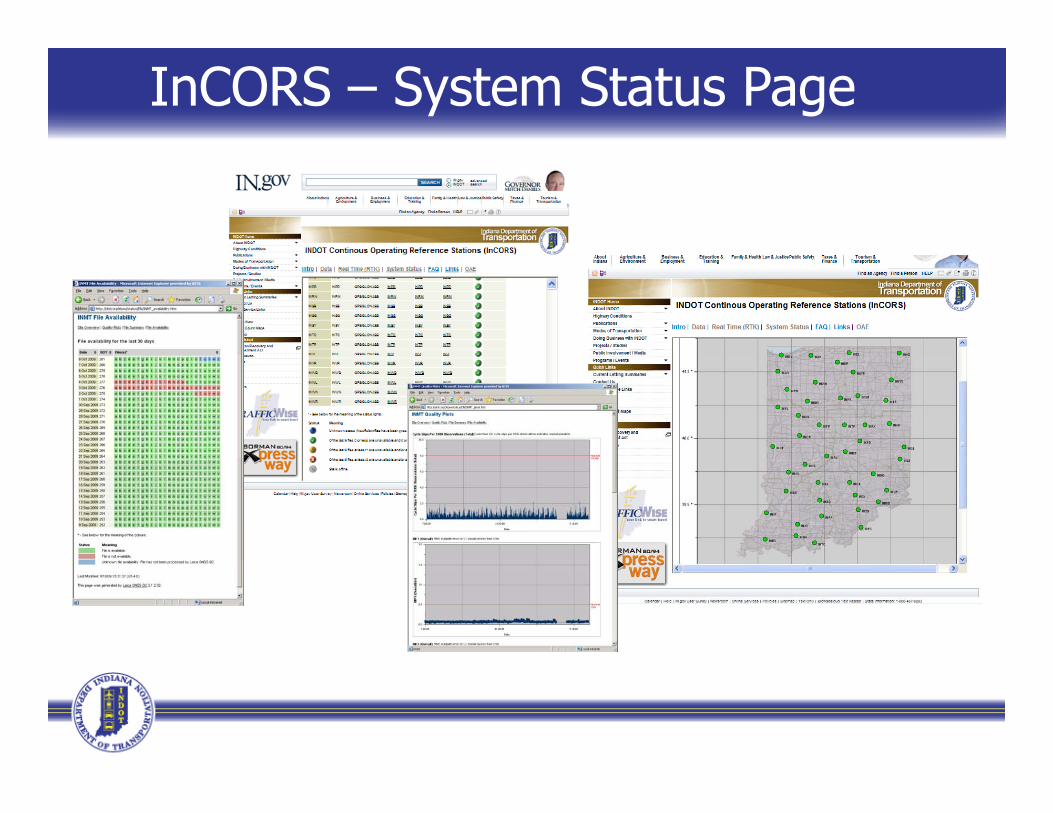
InCORS – System Status Page
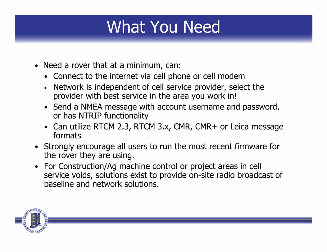
What You Need
• Need a rover that at a minimum, can:• Connect to the internet via cell phone or cell modemConnect to the internet via cell phone or cell modem• Network is independent of cell service provider, select the
provider with best service in the area you work in!• Send a NMEA message with account username and password, g p ,
or has NTRIP functionality• Can utilize RTCM 2.3, RTCM 3.x, CMR, CMR+ or Leica message
formats• Strongly encourage all users to run the most recent firmware for
the rover they are using.• For Construction/Ag machine control or project areas in cell
service voids solutions exist to provide on site radio broadcast ofservice voids, solutions exist to provide on-site radio broadcast of baseline and network solutions.
21
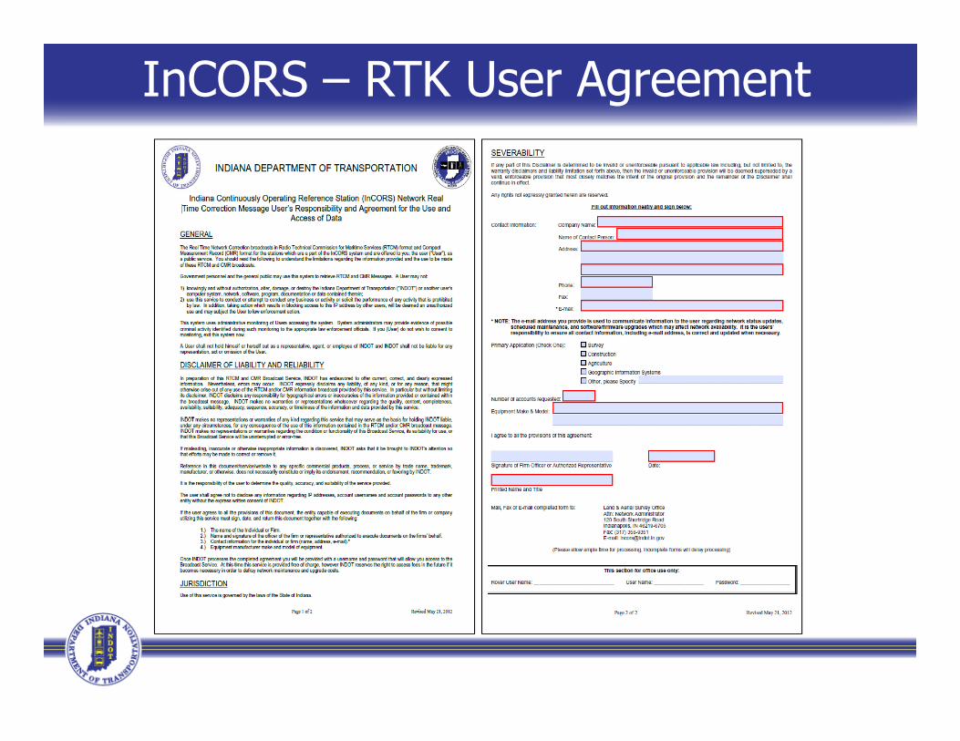
InCORS – RTK User Agreement

RTK User Accounts
• After we receive your signed agreement• We will register you into SpiderNet• Username & password assigned• Email sent out w/ info/
Typical email information:Th IP dd iThe IP address is: xx.xxx.xx.xxxThe port is: 10000 for NTRIP which includes: RTCM 2.3, 3.0, etcUser Name: xxxxxxx Password: xxxxxxxxIf you need TCP/IP connection please send email request…y / p qTech support document attached

Spider Website for Users Login to Spider at http://10.114.30.153/sbc/
Within Spider you will be able: Change your password Update contact information
C t t f i f ti d ti Contact us for information and questions

InCORS Network AdministrationInCORS Network Administration (Behind the Scenes)
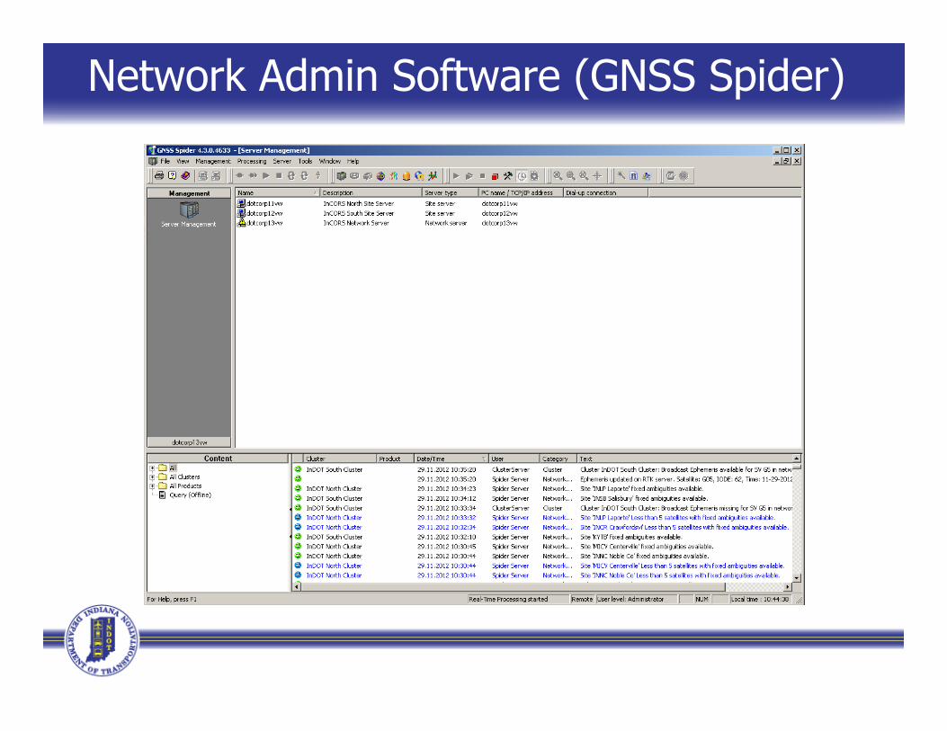
Network Admin Software (GNSS Spider)

North Site Server (dotcorp11vw)
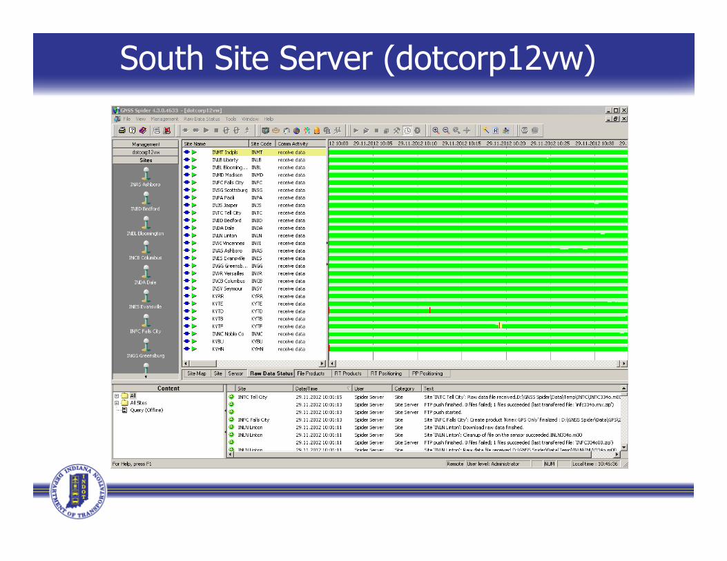
South Site Server (dotcorp12vw)
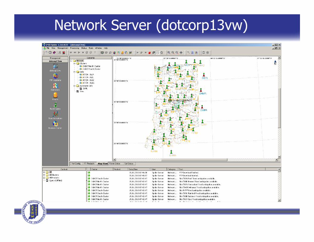
Network Server (dotcorp13vw)
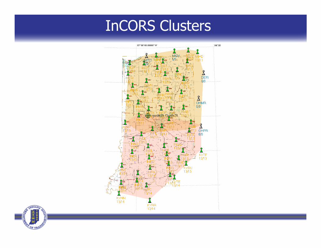
InCORS Clusters
InCORS Network BroadcastInCORS Network Broadcast Corrections
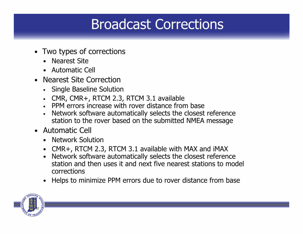
Broadcast Corrections
• Two types of corrections• Nearest Site• Automatic Cell
• Nearest Site Correction• Single Baseline Solution• CMR, CMR+, RTCM 2.3, RTCM 3.1 available• PPM errors increase with rover distance from base• Network software automatically selects the closest reference
station to the rover based on the submitted NMEA message• Automatic Cell• Automatic Cell
• Network Solution• CMR+, RTCM 2.3, RTCM 3.1 available with MAX and iMAX• Network software automatically selects the closest reference
t ti d th it d t fi t t ti t d lstation and then uses it and next five nearest stations to model corrections
• Helps to minimize PPM errors due to rover distance from base
32
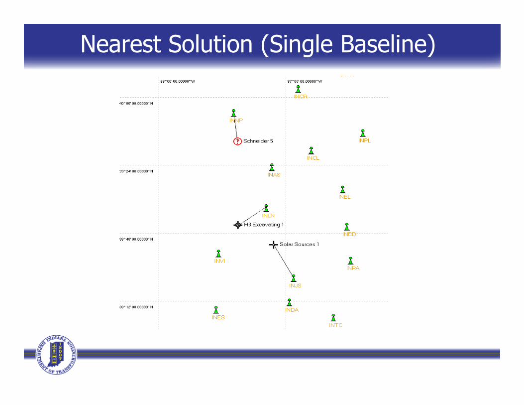
Nearest Solution (Single Baseline)
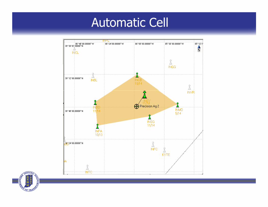
Automatic Cell
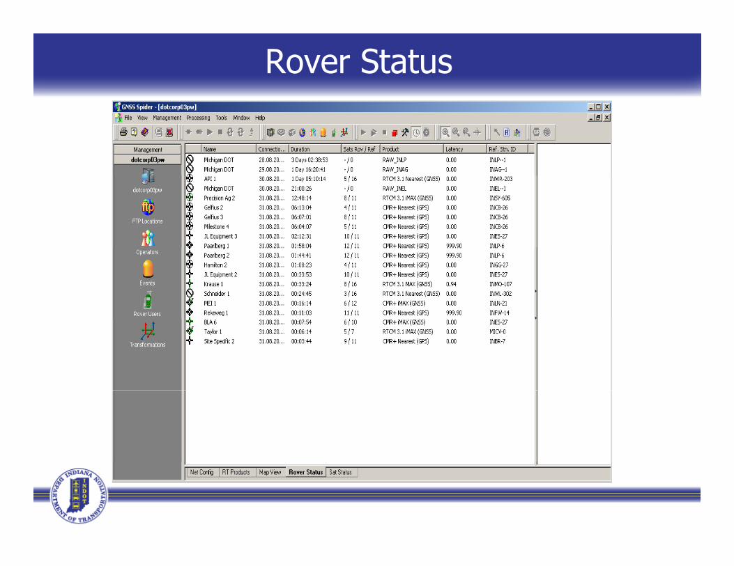
Rover Status
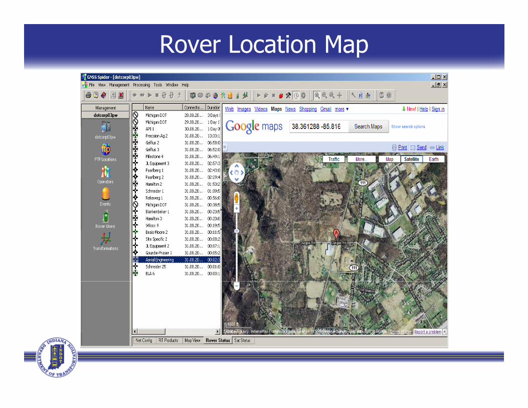
Rover Location Map

Leica Geosystem’sFocus on Network Solution
Concepts for the Indiana RTNConcepts for the Indiana RTN
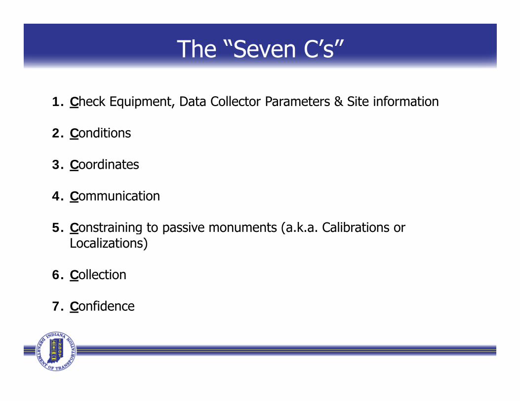
The “Seven C’s”
1. Check Equipment, Data Collector Parameters & Site information
2. Conditions
3. Coordinates
4. Communication
5 Constraining to passive monuments (a k a Calibrations or5. Constraining to passive monuments (a.k.a. Calibrations or Localizations)
6 Collection6. Collection
7. Confidence
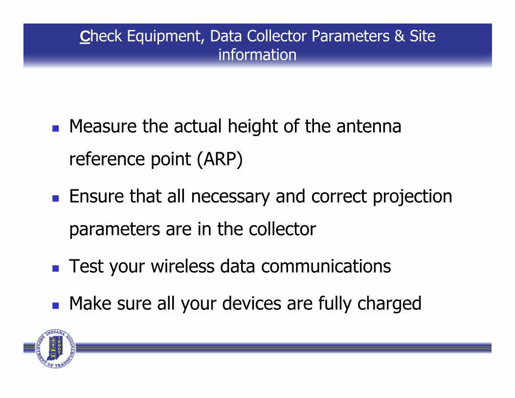
Check Equipment, Data Collector Parameters & Site information
Measure the actual height of the antenna Measure the actual height of the antenna
reference point (ARP)
Ensure that all necessary and correct projection
t i th ll tparameters are in the collector
Test your wireless data communicationsy
Make sure all your devices are fully charged
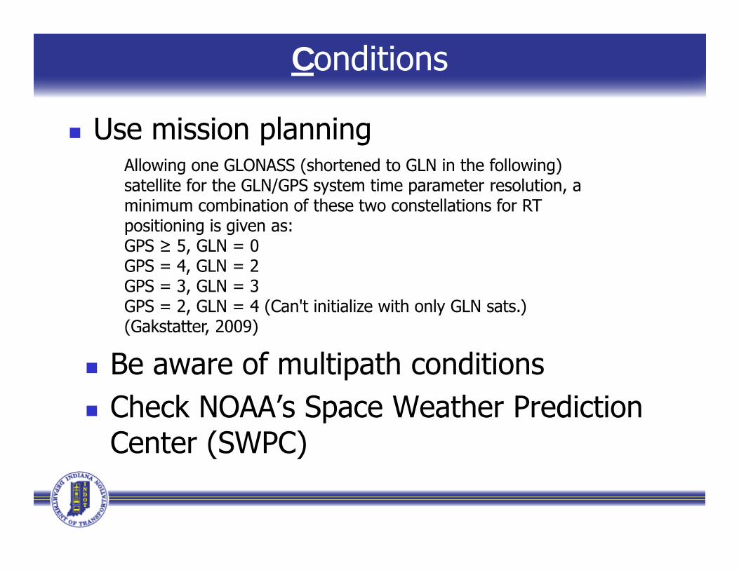
Conditions
Use mission planningAllowing one GLONASS (shortened to GLN in the following)satellite for the GLN/GPS system time parameter resolution, aminimum combination of these two constellations for RTpositioning is given as:GPS ≥ 5 GLN = 0GPS ≥ 5, GLN 0GPS = 4, GLN = 2GPS = 3, GLN = 3GPS = 2, GLN = 4 (Can't initialize with only GLN sats.)(G k t tt 2009)(Gakstatter, 2009)
Be aware of multipath conditions Check NOAA’s Space Weather Prediction
Center (SWPC)
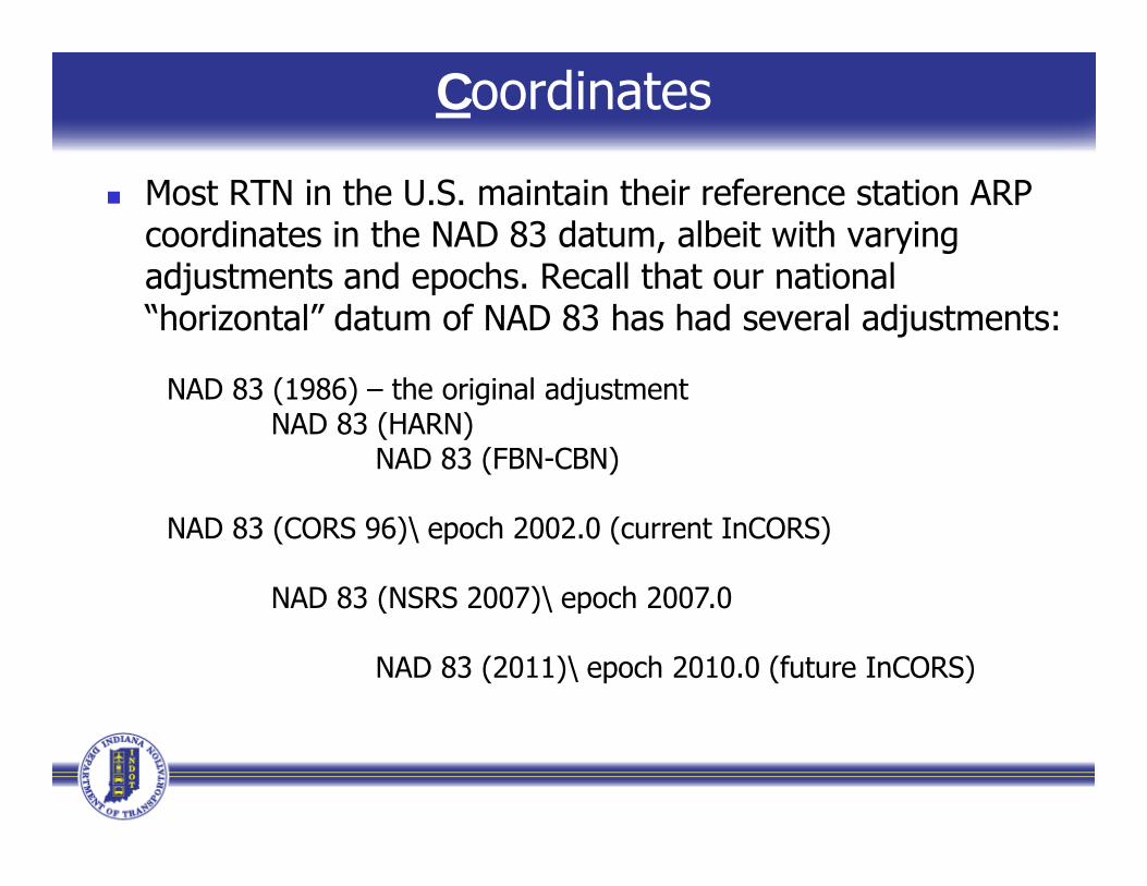
Coordinates
Most RTN in the U.S. maintain their reference station ARP coordinates in the NAD 83 datum, albeit with varying adjustments and epochs Recall that our nationaladjustments and epochs. Recall that our national “horizontal” datum of NAD 83 has had several adjustments:
NAD 83 (1986) the original adjustmentNAD 83 (1986) – the original adjustmentNAD 83 (HARN)
NAD 83 (FBN-CBN)
NAD 83 (CORS 96)\ epoch 2002.0 (current InCORS)
NAD 83 (NSRS 2007)\ epoch 2007.0( )\ p
NAD 83 (2011)\ epoch 2010.0 (future InCORS)
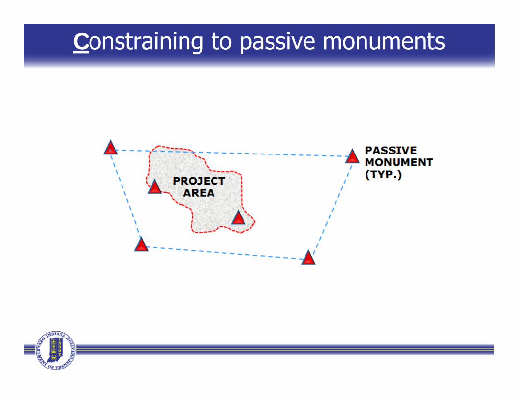
Constraining to passive monuments
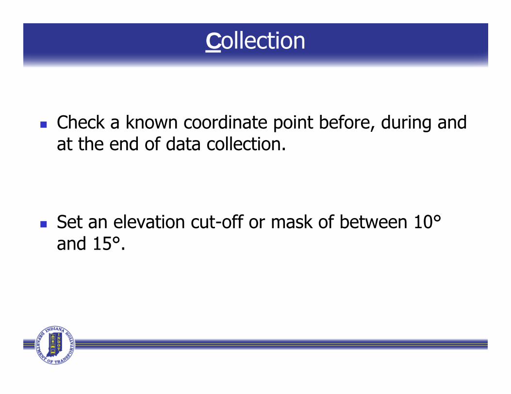
Collection
Check a known coordinate point before during and Check a known coordinate point before, during and at the end of data collection.
Set an elevation cut-off or mask of between 10° Set an elevation cut-off or mask of between 10and 15°.
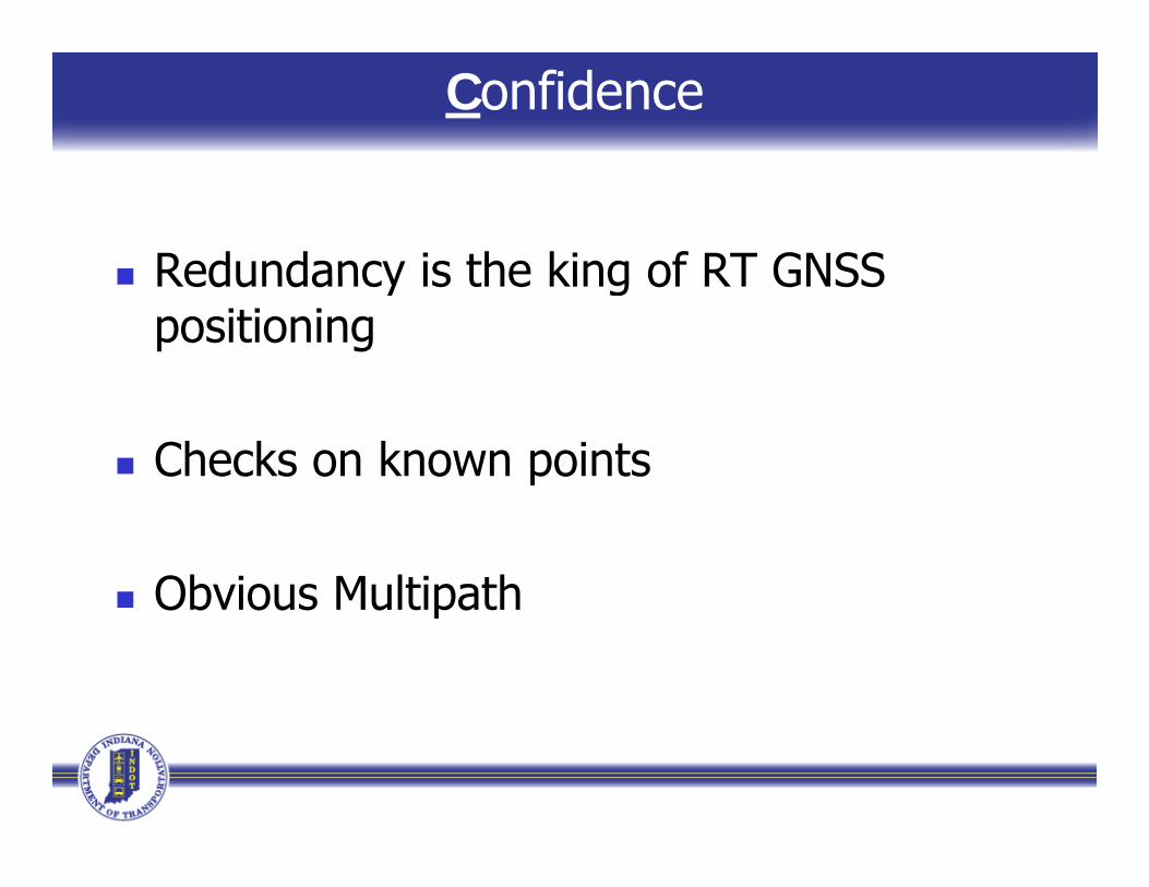
Confidence
Redundancy is the king of RT GNSS Redundancy is the king of RT GNSS positioning
Checks on known points
Obvious Multipathp
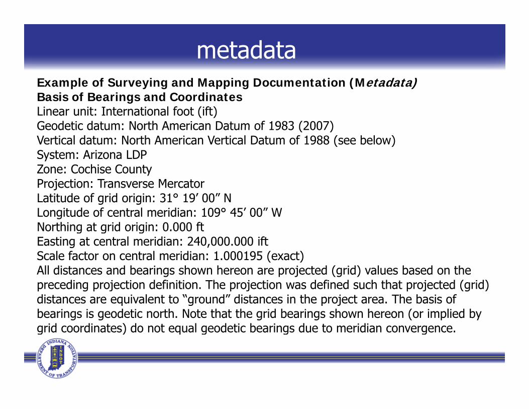
metadataExample of Surveying and Mapping Documentation (Metadata)Basis of Bearings and CoordinatesLinear unit: International foot (ift)Geodetic datum: North American Datum of 1983 (2007)Geodetic datum: North American Datum of 1983 (2007)Vertical datum: North American Vertical Datum of 1988 (see below)System: Arizona LDPZone: Cochise CountyProjection: Transverse MercatorLatitude of grid origin: 31° 19’ 00” NLongitude of central meridian: 109° 45’ 00” WNorthing at grid origin: 0.000 ftNorthing at grid origin: 0.000 ftEasting at central meridian: 240,000.000 iftScale factor on central meridian: 1.000195 (exact)All distances and bearings shown hereon are projected (grid) values based on the
di j ti d fi iti Th j ti d fi d h th t j t d ( id)preceding projection definition. The projection was defined such that projected (grid) distances are equivalent to “ground” distances in the project area. The basis of bearings is geodetic north. Note that the grid bearings shown hereon (or implied by grid coordinates) do not equal geodetic bearings due to meridian convergence.g ) q g g g
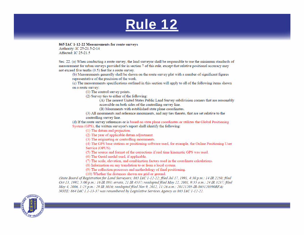
Rule 12
INDOT Mission & Values
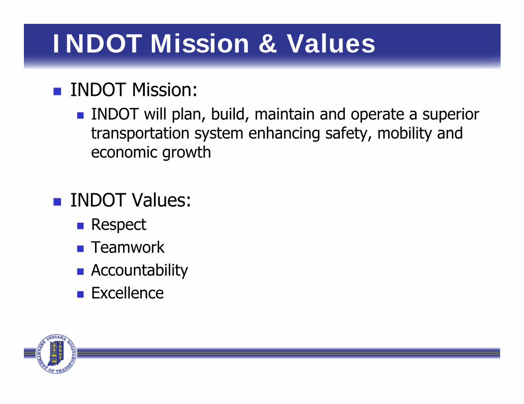
INDOT Mission: INDOT will plan, build, maintain and operate a superior
transportation system enhancing safety, mobility and economic growth
INDOT Values: Respect Respect Teamwork Accountabilityy Excellence

Contact Information
For Questions/Issues e-mail:• [email protected]@ g
• Eric Banschbach, PLS• Manager – Land & Aerial Survey Office
b hb h@i d t i• [email protected]• 317-610-7251, ext. 205
• Andrew “Dee” Baxter, PLS,• Survey Section Coordinator• InCORS Administrator
abaxter@indot in gov• [email protected]• 317-610-7251, ext. 293