guidelines for road design on brownfield sites/media/busind/techstdpubs/road...guidelines for road...
TRANSCRIPT

Guidelines for Road Design on Brownfield Sites July 2013

Guidelines for Road Design on Brownfield Sites, Transport and Main Roads, July 2013
Copyright
http://creativecommons.org/licenses/by/3.0/au/
© State of Queensland (Department of Transport and Main Roads) 2013
Feedback: Please send your feedback regarding this document to: [email protected]

Guidelines for Road Design on Brownfield Sites, Transport and Main Roads, July 2013 i
Amendment Register
Issue /
Rev no.
Reference
section Description of revision Authorised by Date
1 Initial Release of 1st Edition Steering Committee July 2013

Guidelines for Road Design on Brownfield Sites, Transport and Main Roads, July 2013 ii
Foreword
These guidelines have been prepared for immediate use by practitioners throughout the State. This
document concentrates on geometric design requirements and further work is required on:
pavements
bikeways
busways
intersections
drainage
drainage structures
roadway lighting.
It is intended that these guidelines ultimately be incorporated into the Road Planning and Design
Manual (RPDM 2nd
Edition) to become an integral part of the design and planning process.
In the meantime, these guidelines are to be adopted throughout the department for all relevant
designs in conjunction with the RPDM. Many issues to be addressed in Brownfield sites are already
addressed in the RPDM 2nd
Edition and that document should be regarded as the prime source of
information for designers when dealing with a design problem. In all cases, use of design exceptions
should be seen as a last resort to achieve the best value for money outcome.
Comments and suggestions for improvements to this document based on the experience gained with
its use should be forwarded to the Director (Road Design) so that adjustments can be considered and
implemented where required in subsequent revisions.

Guidelines for Road Design on Brownfield Sites, Transport and Main Roads, July 2013 iii
Acknowledgements
This document has been prepared under the guidance of the Steering Committee and Sponsor
comprising:
Julie Mitchell - Chief Engineer (Engineering and Technology)
Noel Dwyer - Deputy Chief Engineer (Geospatial, Road Design and Competency)
Ken Beattie
Bruce Ollason – Executive Director (Special Projects)
Terry Hill
The detailed work required to develop the Guidelines was undertaken by the Working Group
comprising:
David Witherspoon (Project Management)
Robert McPherson (Consultant)
Dr Owen Arndt (TMR)
Ricky Cox (TMR)
Dennis Tennant (TMR)
Jon Douglas (TMR)
Roger Hacquoil (TMR)
Anne-Marie Foley (TMR)
With assistance as required from:
Sid Cotter (TMR)
Simon Harrison (TMR)
Andrew Burbridge (TMR)
Susan Barlow (TMR)
Mark McDonald (TMR)
Ray Cameron (TMR)
David Bobbermen (TMR)
David Hubner (TMR)
Gary Lovell (KBR)
Brian Keller (Parsons Brinkerhoff)
Eric Van Dyk (AECOM)
Guidelines prepared by:
Les Louis (Road Design Consultant and Author)
Professor Rod Troutbeck (Research Consultant)

Guidelines for Road Design on Brownfield Sites, Transport and Main Roads, July 2013 iv
The input from all areas of the department and consulting engineers has been essential to the
development and completion of this document and is gratefully acknowledged. Additional comment
has been provided by other departmental officers and in particular, the members of the Bruce Highway
Upgrade Project team. David Bobbermen and David Hubner have provided insightful comments,
which have led to improvements in several of the design features discussed.
In addition, information has been supplied freely by other State Road Authorities (refer to the
References) – their assistance is gratefully acknowledged.

Guidelines for Road Design on Brownfield Sites, Transport and Main Roads, July 2013 v
Contents
1 Introduction .................................................................................................................................... 1
1.1 Background ..................................................................................................................................... 1
1.2 Purpose ........................................................................................................................................... 1
1.3 Design classes ................................................................................................................................ 1
1.4 Definitions ....................................................................................................................................... 3
1.5 Application of these guidelines ....................................................................................................... 4
2 Literature review ............................................................................................................................ 4
2.1 Documents examined ..................................................................................................................... 4
2.2 Findings .......................................................................................................................................... 5
2.2.1 General ........................................................................................................................... 5 2.2.2 Some legal issues .......................................................................................................... 5 2.2.3 Justifying design exceptions ........................................................................................... 6 2.2.4 Mitigation strategies........................................................................................................ 7 2.2.5 Risk management and value engineering ...................................................................... 7 2.2.6 Monitoring of the finished product .................................................................................. 8
2.3 RPDM provisions ............................................................................................................................ 9
3 Principles ...................................................................................................................................... 10
3.1 Legal aspects ................................................................................................................................ 10
3.2 Design domain .............................................................................................................................. 10
3.3 Project types ................................................................................................................................. 11
3.4 Mitigation strategies ...................................................................................................................... 11
4 The EDD and design exception process ................................................................................... 11
4.1 General ......................................................................................................................................... 11
4.2 Process ......................................................................................................................................... 12
4.2.1 General ......................................................................................................................... 12 4.2.2 Developing alternatives ................................................................................................ 13 4.2.3 Evaluation and risk assessment ................................................................................... 13 4.2.4 Risk management categories ....................................................................................... 15 4.2.5 Mitigation ...................................................................................................................... 18 4.2.6 Review and documentation .......................................................................................... 18 4.2.7 Monitoring and evaluation ............................................................................................ 20
5 Specific design elements for consideration ............................................................................. 23
5.1 Cross section elements ................................................................................................................ 23
5.1.1 Lane widths .................................................................................................................. 23 5.1.2 Shoulder widths ............................................................................................................ 25 5.1.3 Curve widening ............................................................................................................. 27 5.1.4 Medians ........................................................................................................................ 27 5.1.5 Summary – carriageway widths - rural ......................................................................... 29 5.1.6 Need for formation widening when overlaying ............................................................. 37 5.1.7 Sliver widening ............................................................................................................. 42 5.1.8 Single or both sides widening ....................................................................................... 42 5.1.9 Fill batter slopes ........................................................................................................... 42 5.1.10 Lay-bys ......................................................................................................................... 43 5.1.11 Verge ............................................................................................................................ 43 5.1.12 Clear Zone .................................................................................................................... 44 5.1.13 Installation of safety barriers ........................................................................................ 47 5.1.14 Overtaking lanes and climbing lanes............................................................................ 51

Guidelines for Road Design on Brownfield Sites, Transport and Main Roads, July 2013 vi
5.1.15 Floodways .................................................................................................................... 52
5.2 Sealing unsealed pavements ........................................................................................................ 54
5.3 Crest curves .................................................................................................................................. 54
5.3.1 Overview ....................................................................................................................... 54 5.3.2 Developing alternatives ................................................................................................ 55 5.3.3 Evaluation ..................................................................................................................... 57 5.3.4 Mitigation strategies...................................................................................................... 58 5.3.5 Review and documentation .......................................................................................... 59
5.4 Horizontal curves .......................................................................................................................... 60
5.4.1 Overview ....................................................................................................................... 60 5.4.2 Mitigation strategies...................................................................................................... 61
5.5 Intersections .................................................................................................................................. 64
5.5.1 Island size ..................................................................................................................... 64 5.5.2 Turning lanes ................................................................................................................ 65 5.5.3 Private accesses .......................................................................................................... 66
5.6 Temporary works .......................................................................................................................... 67
6 Conclusions ................................................................................................................................. 67
6.1 General ......................................................................................................................................... 67
6.2 Procedures .................................................................................................................................... 68
6.3 Recommendations ........................................................................................................................ 68
7 References .................................................................................................................................... 69
Appendix A: Example EDD and Design Exception Summary Report ................................................... 74
Appendix B: Mitigation Strategies ......................................................................................................... 78
Appendix C: Application of Crash Modification Factors ........................................................................ 81
Appendix D: DTMR Guideline on Shoulder Widths to Support Cycling ................................................ 83
Appendix E: Wide Central Line Marking Safety Treatments ................................................................. 84
Appendix F: Shoulder Widening on Horizontal Curves ......................................................................... 95
Appendix G: EDD and Design Exception Report Applications ............................................................ 100

Guidelines for Road Design on Brownfield Sites, Transport and Main Roads, July 2013 vii
Figures
Figure 4.1: Process for Design Exceptions ........................................................................................... 12
Figure 4.2: Example of a Monitoring Programme ................................................................................. 22
Figure 5.1: Wide Centre Line Treatment showing ATLM treatment ...................................................... 28
Figure 5.2: Relative Crash Rate versus Total Seal Width ..................................................................... 30
Figure 5.3: Example indicating where the formation does not need to be widened.............................. 38
Figure 5.4: Example of formation widening on embankment by steepening batters ............................ 39
Figure 5.5: Example of formation widening on embankment by widening the earthworks footprint
(widening both sides shown) ................................................................................................................. 40
Figure 5.6: Example of formation widening in cuttings by widening the earthworks footprint (widening
both sides shown) .................................................................................................................................. 40
Figure 5.7: Example of providing a narrower pavement/carriageway width when constructing a wider
formation (widening the earthworks footprint on both sides shown) ..................................................... 41
Figure 5.8: Example of a parallel fill slope design illustrating clear zone and slopes ........................... 45
Figure 5.9: Clear zone transition on approach to horizontal curves ...................................................... 46
Figure 5.10: Retrofitting Transition Curves ............................................................................................ 61
Figure 5.11: Right Hand Curve Alignment ............................................................................................. 63
Figure 5.12: Shoulder widening on isolated curves .............................................................................. 63
Figure 5.13: Requirements for islands from Austroads GRD Part 4A ................................................... 64
Figure 5.14: Example Private Entrance Widening - Hook Right Turns ................................................. 67
Figure C1: Crash Modification Factors for Traffic Lane Width (Stein and Neuman 2007) .................... 82
Figure C2: Crash Modification Factors for Shoulder Width on two lane rural highways ....................... 82
Tables
Table 1.1: Road Design Classes ............................................................................................................. 2
Table 4.1: Considerations for various Risk Categories ......................................................................... 17
Table 4.2: Potential Content of a Design Exception Report .................................................................. 20
Table 5.1: Proposed minimum pavement widths for two-way two-lane roads (Normal Design Domain)
............................................................................................................................................................... 24
Table 5.2: Proposed pavement widths for two-way two-lane roads (Extended Design Domain) ......... 25
Table 5.3: Functions of shoulders ......................................................................................................... 26
Table 5.4: Sealed Shoulder Default Widths .......................................................................................... 26
Table 5.5: Crash Modification Factors (for run off the road, head-on and side-swipe crashes) ........... 31

Guidelines for Road Design on Brownfield Sites, Transport and Main Roads, July 2013 viii
Table 5.6: Examples of Carriageway widths (Design Exceptions) for passing lane sections (existing
formations) ............................................................................................................................................. 51
Table 5.7: Definitions of Access Levels ................................................................................................. 52
Table 5.8: Manoeuvre distances and K values – potential justification for design exceptions ............. 56
Table 5.9: Relative risk ratios for sight distance deficiencies on crests ................................................ 58

Guidelines for Road Design on Brownfield Sites
Guidelines, Transport and Main Roads, July 2013 1
1 Introduction
1.1 Background
Past road design guidelines have tended to provide values of parameters that are suitable for the
design of roads in Greenfield sites i.e. where minimal constraints exist. These are referred to as
Normal Design Domain (NDD) values. Much of the work on roads is now concentrated on existing
roads where a range of constraints exist and Normal Design Domain values cannot always be applied
if an economical outcome is to be achieved.
Over the last 10 years, additional guidance for designing in brownfield sites has been progressively
introduced into the RPDM, for example:
Additional material on design philosophy, including the concept of Design Domain
Introduction of the concept of Extended Design Domain (EDD)
Introduction of the concept of Design Exceptions.
1.2 Purpose
The purpose of these guidelines is to expand on the previous work on designing in brownfield sites. In
particular, they seek to provide:
a robust approach for determining the suitability of design exceptions and their justification
additional EDD criteria, if sufficient latitude can be shown to exist in the NDD criteria
guidance on the provision of road safety treatments for retrofitting to existing roads e.g. wire
rope barriers in narrow medians, wire rope barriers on hinge points, narrow painted medians.
1.3 Design classes
Transport and Main Roads (TMR) has undertaken work on the development of Design Classes
(initially in the TNRP Design Guidelines) which will be incorporated in the 2nd Edition of the Road
Planning and Design Manual 2nd
Edition. Table 1.1 shows the information to be included and
illustrates how the design classes interact with both Greenfield and Brownfield sites (refer to RPDM
2nd
Edition Volume 1).

Guidelines for Road Design on Brownfield Sites
Guidelines, Transport and Main Roads, July 2013 2
Table 1.1: Road Design Classes
Road
Design
Class
Project Types Geometric
Changes
Typical Geometric
Parameters/Elements
Assessed#
Minimum Design
Criteria for
Assessed
Parameters
A
New roads, or
Complex, high risk and/or relatively expensive projects involving modification to existing roads e.g.
duplication of existing roads
>500m realignment of existing road
new climbing / overtaking lanes.
New alignments or major modifications to existing roads
All EDD* if a brownfield site
Design exception, if an exceptional circumstance
NDD for all other instances
B
Sealing of an unsealed road, or
Restoration projects (roads and/or intersections) involving increases to the earthworks footprint for most of the project length e.g.
shoulder widening
overlay and widening.
Major cross-sectional changes including road widening
All EDD* otherwise NDD
Design exception where prohibitively expensive to justify
C
Restoration projects (roads and/or intersections) where the earthworks footprint does not change or there is localised marginal change to the footprint. This includes projects with:
significant increases in seal width
structural overlays
surface shape correction
full shoulder seal projects (if the change in seal width is likely to significantly increase driver speed, use Class B)
batter flattening/ reshaping.
Surface profile changes that do not involve road widening
i) Crossfalls
ii) Superelevation
iii) Flow path depths at curve transitions.
iv) Verge width and sight distance requirements, if retrofitting roadside barriers.
v) Geometric elements associated with a significant crash history (in spite of existing appropriate mitigating devices).
For geometric parameters i) to iii) in previous column: EDD* otherwise NDD. For geometric parameters iv) in previous column: a) EDD* otherwise NDD; b) design exception if prohibitively expensive to justify. For geometric elements: v) in previous column, consider: a) EDD* otherwise NDD (remove hazard); or b) application of suitable mitigating devices.. For all other geometric parameters/elements other than i) to v) in previous column, retain design exceptions.
D
Maintenance type projects that do not involve structural overlays, formation widening or significant increases in seal width, but where some heavy / specialised plant is required, as given by the examples in the dot points below.
None – restoring existing geometry, (except for very minor and localised surface profile changes)
i) verge width and sight distance requirements, if retrofitting roadside barriers
ii) geometric elements with crash histories identified in Road Safety Audits.
For geometric parameters i) in previous column:
a) EDD* otherwise NDD
b) design exception if prohibitively expensive to justify.

Guidelines for Road Design on Brownfield Sites
Guidelines, Transport and Main Roads, July 2013 3
Road
Design
Class
Project Types Geometric
Changes
Typical Geometric
Parameters/Elements
Assessed#
Minimum Design
Criteria for
Assessed
Parameters
pavement rehabilitation
minor overlays (small height increase)
resheet of unsealed road
reseal
part shoulder seal
signs (e.g. advisory speed signs; CAMS)
safety barriers
Where the pavement is not being rehabilitated/ reconstructed, the roadway must have retained its shape with respect to crossfall and grade to classify as Class D.
For geometric elements ii) in previous column, apply suitable mitigating devices.
For all other geometric parameters/elements other than i) to ii) in previous column, retain design exceptions.
# In this table, geometric parameters are defined as those that impact the shape of roadway formation e.g. parameters that effect the horizontal and vertical alignment, cross section, intersection geometry etc. Examples of such parameters are lane width, batter slope, stopping sight distance, side friction, intersection turn treatment type and taper length.
* Where an EDD exists
It is critical that designers firstly identify the most appropriate design class for a given project before
applying these Brownfield Guidelines. This is because not all of the design criteria in these guidelines
need to be applied for each design class. For example, design criteria for crest vertical curve size and
carriageway width will not normally be applied on a Class D part shoulder sealing project. Refer to the
fourth column of Table 1.1 to identify relevant geometric parameters or elements to be assessed for
each design class. For parameters and/or elements other than those mentioned within design classes
C and D a detailed EDD and Design Exceptions Summary Report will usually not be necessary as a
geometric assessment of these parameters is not required. Refer to Section 4.2.6 for documentation
requirements.
1.4 Definitions
The NSW Roads and Traffic Authority (RTA) [now the Roads and Maritime Services (RMS)]
Brownfields Road Design Guidelines defines brownfield sites as “locations on existing roads where
work proposals are based on retaining the existing formation to the greatest degree feasible”. On
Greenfield sites, similar considerations may be given to those locations where the existing road
infrastructure creates constraints that make the application of the NDD impracticable and/or
uneconomic.
A broader definition (ARRB 2012 page 1) applicable to Queensland conditions is:
A brownfield site, is one where infrastructure, such as the road pavements; utilities, such as power
lines, telecommunication lines, water and sewer services; drainage systems, vegetation and the
access to abutting or nearby properties has been in place for some time. Removing, altering or
adjusting this existing infrastructure can be very expensive and so often, the retention of this
infrastructure is required to minimise the costs of the work. There are also many cultural, heritage or
environmental issues to be considered.

Guidelines for Road Design on Brownfield Sites
Guidelines, Transport and Main Roads, July 2013 4
A further constraint on a brownfield site may be the need to retain all or part of the road in service
during the course of the works. These requirements can then place limitations or constraints on the
design.
Normal Design Domain (NDD), Extended Design Domain (EDD) and Design Exceptions are
defined in Volume 1 of the RPDM 2nd
Edition.
Nominal safety is produced by a design that complies with design criteria, warrants and guidelines,
and sanctioned design procedures.
Substantive safety is the measured or expected crash frequency and severity.
1.5 Application of these guidelines
These Guidelines examine current practice in Queensland, other Australian states and other countries
in respect to dealing with EDD and design exceptions with a view to establishing a robust procedure
for developing acceptable processes for designs on brownfield sites. It is not practical (or wise) to
produce a “cook book” for acceptable design parameters for individual situations since every
brownfield site will be unique. However, additional guidance for the appropriate approach to adopting
acceptable designs for individual sites will be developed.
It is worth noting that Parker (2012 page 13) states (with respect to a case described):
This case is important because it highlights the lesson that guidelines must be applied with careful
analysis. It is not sufficient to blindly follow provisions in a manual: the provisions in the
manual must be used in conjunction with engineering judgement and common sense.
(Bolding added by DTMR)
That is, even in the case of NDD, a “cook book” approach is not always acceptable.
This is supported by PIARC (1991 page 74) in its summary of the approach to be taken:
As well as standards, there are results of safety studies (technical guides, information notes) which
can be used to facilitate the conception of the various safety operations. These guides have the
advantage of proposing several degrees of intervention, from simple low cost corrective action to the
typical, radical and generally costly solution. These guides are precious helps but do not dispense with
the necessary thinking. Indeed, for a «localized» operation, although they give a full range of possible
solutions, they do not choose the one which is best, if indeed this is directly adaptable to the site. And
in treating a route, they provide neither the classification nor the combination of operations which lead
to efficiency from the safety point of view.
The greatest encouragement should therefore be given to thinking and discussion; on
condition this is based on real knowledge, not only on knowledge from standards and
regulations, but also that inspired from experience and the results of safety operation follow-
up.
(Bolding added by TMR)
2 Literature review
2.1 Documents examined
A range of documents from various authorities was examined to establish common practices and
issues with respect to design on brownfield sites. Details of all documents reviewed or noted are
included in the References.

Guidelines for Road Design on Brownfield Sites
Guidelines, Transport and Main Roads, July 2013 5
2.2 Findings
2.2.1 General
The documents reviewed show that all of the authorities involved have found it necessary to adopt
procedures to develop acceptable designs outside the normal design domain for brownfield sites. In
the USA and Canada, every deviation from the standards required by the formal guidelines is
regarded as a “design exception”, as opposed to current practice in Queensland and Australia
generally where two levels of deviation from standard guidelines are used – Extended Design Domain
and Design Exceptions.
The over-riding issue for all authorities is that of litigation arising from the adoption of dimensions and
values outside the normal domain. This concern led to the need for robust procedures for design
documentation and risk management. These matters will be dealt with in more detail in other sections
of these guidelines.
2.2.2 Some legal issues
The overriding requirement is for the design decision to be defendable in court and that the
information for this defence is available at the time – often many years after the design was
undertaken and the construction completed.
If possible, it may be helpful to the defence of a design case and ultimately the agency to consider a
policy that specifically states that while safety is an important factor that always will be considered in
the design of a project, it will be balanced with other equally important factors such as economic,
historical and environmental considerations. (Parker 2012 page 5)
If the above approach is taken, then defending the design with the balancing factors analysis
would create expectations that the documentation would contain, as a minimum:
the process and reasoning that led to the decision, including the circumstances of each project
the choices available
the considerations reviewed
a complete explanation for the decision itself.
(Modified from Parker (2012)
In a case quoted in Parker (2012 page 14):
1. the danger imposed by the outdated device or design;
2. the increase in safety the new device or design would provide;
3. the cost of upgrading;
4. the State’s available resources;
5. other known hazards that pose a greater danger to motorists; and
6. any other factors including other needs in the highway system.
The Court reasoned that while the State was likely aware of components in its network that were
outdated, it had a limited budget with many competing demands, and had to prioritize the needs of the
entire system and maximise the use of its limited funds to best serve all of the travelling public.

Guidelines for Road Design on Brownfield Sites
Guidelines, Transport and Main Roads, July 2013 6
This approach has been confirmed in Australian law (refer to Brodie vs Singleton Shire Council (2001)
High Court of Australia). Cox (2004 slides 10,11,12) notes the following:
In deciding a case, courts will consider industry standards in determining duty of care
But simply meeting a standard does not ensure duty of care is met:
Are there other factors that require something different / better in order to provide
‘reasonable safety’?
Road Authorities need to take ‘reasonable care’ to see if there are users with special
needs
Nor does failure to meet an industry or national standard necessarily mean that a Road
Authority has breached its duty of care
In deciding a case, courts will consider:
Standards at time of design & construction, or when some intervention or modification
made
If standards sufficiently address safety
Available funds vs other priorities
Magnitude, probability & consequence of risk
Expense, difficulty & inconvenience in addressing risk
Crash history.
In signing off on the adopted design, it is important to word the compliance statement carefully. The
document should state that the design is “in compliance with reasonable engineering principles” rather
than “compliance with a particular guideline or standard”.
Note that from a legal perspective, guidelines must be applied with careful analysis as noted in
Section 1.3 above and that the “provisions in the manual must be used in conjunction with engineering
judgement and common sense.”
Parker (2012 – footnote page 18) notes that Engineering Judgement is defined by the MUTCD (USA)
as “the evaluation of available pertinent information and the application of appropriate principles,
provisions contained in this manual and other sources, for the purpose of deciding upon the
applicability, design, cooperation, or installation of a traffic control device”
For the purposes of general road design, it is reasonable to replace the last part with “for the purpose
of deciding the applicability, design or installation of a particular design feature”.
That is, it is necessary to apply engineering analysis and appropriate procedures to arrive at a
conclusion based on “engineering judgement” – it is not sufficient to make a judgement based
on a “gut feel” alone.
2.2.3 Justifying design exceptions
All jurisdictions require comprehensive documentation of the design decisions made, particularly when
variation from the generally accepted design standards is adopted. Some have developed standard
formats to make the process easier and more consistent and to ensure that all of the necessary
factors have been considered and recorded (refer to New Jersey Department of Transportation (2012)
and to RTA (2007)). It is a common requirement that a design exception will not be sought until an

Guidelines for Road Design on Brownfield Sites
Guidelines, Transport and Main Roads, July 2013 7
evaluation of using the generally accepted standards has been undertaken and the adoption of those
standards shown to be impractical from some perspective.
Common reasons for considering design exceptions include:
impacts on the natural environment
social or right-of-way impacts
preservation of historic or cultural resources
sensitivity to context or accommodating community values
construction and/or right-of-way costs.
It is important that approval for such design exceptions is achieved early in the project
development process.
The requirements for considering the use of design exceptions should be identified in the earliest
stages of the project initiation and in Queensland should be fully incorporated in the business case
(preferably having been identified and justified in the Link Strategy and/or Options Development).
2.2.4 Mitigation strategies
Wherever a design exception is adopted, appropriate measures should be taken to mitigate any
adverse effects of the exception.
Designers should recognize, however, that design exceptions have the potential to negatively
affect highway safety and traffic operations. For this reason, consideration of a design
exception should be deliberative and thorough and a clear understanding of the potential
negative impacts should be developed.
If the decision is made to go forward with a design exception, it is especially important that
measures to reduce or eliminate the potential impacts be evaluated and, where appropriate,
implemented
(Stein and Neuman 2007 - Mitigation Strategies for Design Exceptions – page 1)
(Bolding added by DTMR)
This document (Stein and Neuman 2007 page 67) provides a listing of possible mitigation treatments
as well as some case studies. It cautions that:
Every design exception location is unique. The recommended approach is to consider the
mitigation strategies presented -- as well as other ideas and new approaches. If available,
consult current research to gain additional information. Then customize one or more strategies
to address the unique concerns and site conditions at the design exception location.
Potential mitigation strategies and features are developed in several of the documents listed in the
references. Specific values for the mitigation effects of various countermeasures (or mitigation
strategies) are provided in Oxley et al (2004). Further useful information is included in NCHRP
Synthesis 432 (2012). The NCHRP Report 500 Guidelines are a potential source of information on
suitable mitigation strategies for a range of design exceptions.
2.2.5 Risk management and value engineering
All jurisdictions recognise that road design must adopt a risk management approach to the
development of the designs, perhaps regardless of whether the values used are within the generally

Guidelines for Road Design on Brownfield Sites
Guidelines, Transport and Main Roads, July 2013 8
accepted standards or not. It is especially important if the values used are exceptions. Stein and
Neuman (2007 page 16) note:
Agencies are confronted with two fundamental types of risk when dealing with design
exceptions. The first involves the risk of the solution not performing as expected. The second
involves the risk concerning the agency’s ability to defend itself against potential legal actions
as a result of its decisions.
These risks can be addressed by adopting a rigorous approach to developing the design and
recording the decisions made and the reasons for them.
For example RTA NSW (2007) requires a value engineering assessment of its projects in conjunction
with the risk assessment. The focus of this assessment is to review each element of a project to
establish whether the associated capital expenditure represents the best use of scarce community
resources.
This RTA Guide also defines the situations for various levels of design (Section 2.9) into:
Retain Existing Design (RE)
Evaluate Upgrade Design (EU)
Full Design (FD).
In addition, a Permitted Variation from the limiting values defined by the Road Design Guide may be
approved after a risk and value engineering assessment of the impacts of the variation. Adoption of
such a variation may also require various mitigation measures to be adopted.
Tabulations of the design elements that may be involved against the expected type of works and the
design strategy (RE, EU or FD) to be used are provided. This is, in some ways, similar to the “Design
Classes” adopted by DTMR.
For risk management refer to TMR policies and procedures. OnQ Project Management acknowledges
and integrates these processes as part of the risk management knowledge area.
Cox (2004 slide 17) also notes with respect to risk management and assessment:
2004 Queensland Supreme Court decision (Theden) – “The assessment of risk ought properly
to be taken from an assessment of the configuration rather than any crash statistics”
This would indicate that it is not reasonable to rely on a lack of crashes when there are low
traffic volumes.
EDD does not rely on a lack of crashes, but on a reasonable level of capability.
Austroads (2010a) and Austroads (2010b) provide objective data on crash risk and crash risk
reduction factors. These publications may be useful in assessing the relative merits of proposed works
to improve safety and in assessing the relative differences between implementing projects with full
EDD standards and those with design exceptions.
2.2.6 Monitoring of the finished product
From a legal perspective, it is necessary to demonstrate that the agency has in place appropriate
procedures to monitor the results of its designs, particularly when design exceptions are used. That is,
the agency should be able to answer the question “Did the design adopted perform as expected?” and
show how its procedures have been modified (if required) as a result.

Guidelines for Road Design on Brownfield Sites
Guidelines, Transport and Main Roads, July 2013 9
Such monitoring may have to extend for a considerable period of time. For example, RTA has a
requirement to determine the issues to be reviewed after completion, after five years in service and
after fifteen years in service.
Parker (2012 page 17) notes:
Once the decision to balance safety against other factors such as cost and environmental
impact is made, it will be necessary to periodically evaluate projects and roads to determine
whether the tradeoff was worth the risk taken. ---- Periodic safety studies or accident studies
could also be done to ensure adequate performance of the design feature.
Austroads (2010b page 25) makes the observation that research requires robust methodologies and
this is applicable to the matter of monitoring projects in order to assess the success or otherwise of the
decisions made. The report notes:
A lack of robust research has been highlighted in this study. Where research has been conducted, this
is often of low quality and not usable by practitioners. Some form of guidance or training is required for
practitioners and those evaluating treatments. This should be aimed at highlighting the importance of
robust evaluation, as well as the methods that can be used to achieve this. Inappropriate methods
may provide a false impression of the success of a treatment type, thereby leading to incorrect funding
decisions. In addition, this research has provided a simple framework for assessing the
methodological robustness of research (on a scale from 1 to 5, with 1 being the least robust). It is
recommended that this framework or a more refined approach be used in future to evaluate research
quality. It may also be used to help advise research funders on the confidence they should place in
proposed research. It may be that with a better understanding of this issue, better quality research will
be produced.
Particular note should be taken of the comment “Inappropriate methods may provide a false
impression…” and steps taken to ensure that the monitoring is undertaken in a robust manner.
2.3 RPDM provisions
The RPDM 2nd
Edition addresses the requirements for existing sites in several parts of the manual.
Volume 1 (Section 3.1) notes:
All road design is a compromise between the ideal and what is a reasonable outcome (in terms
of cost, safety, driver expectation, economic drivers, environmental impacts and social issues -
refer to Section 3.1.1).
Judgements have to be made on the value of improving the standard of a road and the impact
this might have on the ability to make improvements elsewhere on the road system. These
judgements are usually made on the basis of the level of safety of the road in question and the
Benefit/Cost Ratio (BCR) resulting from the proposed improvements. Environmental and social
impacts are also major considerations.
Specific EDD for some design elements are included in the following:
The Extended Design Domain for sight distance on roads (see also Austroads GRD Part 3)
The Extended Design Domain sight distance at intersections (see also Austroads GRD Part
4A)
Volume 3 Part 3 for guidance in relation to evaluating cross sections using the Extended
Design Domain (see also Austroads GRD Part 3)

Guidelines for Road Design on Brownfield Sites
Guidelines, Transport and Main Roads, July 2013 10
Volume 3 Part 4A for the Extended Design Domain for short length right turn slots (see also
Austroads GRD Part 4A)
Volume 3 Part 3 for the Extended Design Domain for adverse superelevation on horizontal
curves in urban areas (see also Austroads GRD Part 3).
The PPM requires all TMR design to be undertaken using Risk Management. In the management of
design, this document requires Value Management, Value Engineering and Design Review to be
applied to the management of the design process. It also describes the requirements for the
documentation of EDD and Design Exceptions.
3 Principles
3.1 Legal aspects
Some issues with respect to litigation were discussed in Section 2.2.2. In summary, the principles that
can be distilled are:
Designs cannot be undertaken blindly following a manual or guidelines – appropriate
engineering judgement and experience must be applied.
Design decisions should be properly documented in a manner that will provide sufficient
information many years after the design has been implemented.
Certifications should be worded to state that the design “complies with reasonable engineering
principles” not that it “complies with a particular guideline or standard”.
Nominal safety is achieved by compliance with the values stated in the design manual or
guideline (i.e. the RPDM in Queensland). By definition, a design that adopts values outside
these limits is not “nominally safe” and adoption of those values will have to be justified and
that justification documented. Given that EDD values have been subjected to rigorous analysis
before placing them in the RPDM, they may provide for nominal safety by definition provided
they are used in the circumstances defined in the manual.
Design decisions must be defendable in litigation. The expectation would be that the
documentation would contain, as a minimum, the process and reasoning that led to the
decision, including the circumstances of each project, the choices available, and the
considerations reviewed, as well as a complete explanation for the decision itself.
3.2 Design domain
All design decisions should be appropriately documented. NDD values can be assumed to be
documented by the project documents (drawings and specifications) and the RPDM. All other design
decisions will need specific documentation as defined in the RPDM 2nd
Edition. While the overall
documentation required for EDD and Design Exceptions are similar, the EDD values have already
been subjected to rigorous analysis and the documentation is about recording the circumstances that
required such values to be used.
Design exceptions, however, have to be justified in their entirety. That is, the values adopted have to
be justified in terms of their necessity as well as their impact on safety, environmental values and cost.
It will be necessary to demonstrate that adoption of the design exception does not worsen the
substantive safety of the road in question and that level of safety is reasonable.

Guidelines for Road Design on Brownfield Sites
Guidelines, Transport and Main Roads, July 2013 11
3.3 Project types
It is reasonable to define the types of projects where existing features are to be retained and the level
of justification required for their retention. It is also reasonable to determine which types of projects are
not suitable for the consideration of design exceptions.
To a large extent, the RPDM already does this. Design classes are defined as well as the likelihood of
such design classes using design exceptions. The approval processes are defined. Refer to RPDM 2nd
Edition Volume 1 Section 3.3 and Table 3.1.
3.4 Mitigation strategies
Some form of mitigation of adverse effects must be incorporated to offset the lower design values
used when adopting EDD or Design Exceptions. This ranges from higher than normal values for other
elements of the design to providing additional signage and marking. In some cases, reduction of the
speed limit may be appropriate.
The Safe System approach may be helpful in providing guidance for selecting appropriate mitigation
strategies. Principles of the Safe Systems Approach are discussed in ARRB (2012 page 2). The report
notes:
The Safe System principles are to prevent crashes occurring, or if they do occur, to minimise
the impact on the road user to a level such that they are not killed or seriously injured. The
goal is to reduce fatal and serious injuries from occurring.
The major methods to achieve this are to reduce the potential speed of a crash and/or to make the
roadside as forgiving as possible to allow drivers who make an error to recover without crashing into a
hazard. Designers will need to determine the most appropriate way of achieving this.
In order to determine appropriate mitigation measures, it will be necessary to have a thorough
understanding of the crash history at the site and other similar situations. The types of crashes and
their relationship to the design elements should be determined. It is not acceptable to adopt any form
of design exception for an element that is related to the cause of crashes at the site.
At times, it will be decided that the “design” is to leave the road in its present geometric form even
though upgrading might be normally required. In these circumstances, mitigation strategies may be
applied to reduce the level of risk until the road profile can be upgraded. Obviously the timing of the
upgrade will be an essential input (refer to Section 4.2.3).
Potential mitigation strategies are shown in Appendix B of these Guidelines (from Stein and Neuman
(2007 pages 7 – 70). These strategies are applicable in Queensland conditions.
4 The EDD and design exception process
4.1 General
Section 3.2.2 and Section 3.2.3 of the RPDM 2nd
Edition Volume 1 provide explicit guidance on EDD
and Design Exceptions. The required design process is described in the Preconstruction Processes
Manual (PPM) chapter 4 and this process is appropriate for all design exceptions, not only those on
temporary roads.
Stein and Neuman (2007 page 9) suggests the following:
The following are basic questions designers should ask when contemplating a design exception:

Guidelines for Road Design on Brownfield Sites
Guidelines, Transport and Main Roads, July 2013 12
If this is an existing location and a design exception is being studied, how good (or poor) is the
existing substantive safety performance?
If this is new construction or reconstruction and a design exception is being studied, what
should the long term safety performance of the roadway be?
Given the specifics of the design exception (geometric element, degree/magnitude of the
variance, length of highway over which it is applied, traffic volume, etc.) what is the difference
in expected substantive safety if the exception is implemented?
Addressing these questions is an essential part of developing a case for design exceptions and
provides emphasis for the processes described in the PPM.
4.2 Process
4.2.1 General
PPM Chapter 4 defines the requirements for the process in Section 3; this has been further developed
in Figure 4.1 and provides details for EDD in Section 7.9 and for Design Exceptions in Section 7.10.
Review
background
information
Understand the
required standard
for geometric
elements
Can we retain the
design exception?
Are mitigation
treatments
required?
Review, document
& approve
Review crash data, operating
speeds and other special
considerations
Yes
No
Consider construction
sequencing, methods
and/ redesign
Mitigation of the specific design
exception or generally throughout
the construction site.
Review the
capability provided
by each alternative
Assess costs &
impacts
Conduct a risk
analysis
Identify if there are
other minima
Develop &
evaluate
alternatives
Figure 4.1: Process for Design Exceptions
The process described in FHWA (2008) is robust and the principles of TMR project development
process are covered by it. The elements of this process in order of execution are:

Guidelines for Road Design on Brownfield Sites
Guidelines, Transport and Main Roads, July 2013 13
1. determine the costs and impacts of meeting the NDD
2. develop and evaluate multiple alternatives
3. evaluate risk
4. evaluate mitigation strategies
5. document, review and approve
6. monitor and evaluate in-service performance.
The extent of the work at each phase will depend on the size of the project as well as the degree of
non-conformance anticipated. However, all of the elements need to be addressed to ensure that the
outcome is robust and able to be defended in any litigation that may arise.
4.2.2 Developing alternatives
An adequate defence of a decision to adopt a design exception will require TMR to demonstrate that
before adopting it, an evaluation of the impacts of providing the minimum or better design values has
been undertaken. Alternatives including one that meets NDD standards will need to be developed and
evaluated.
Evaluation and assessment will require (modified from Parker (2012) – Connecticut procedures):
1. Presentation of information to demonstrate the impacts of meeting the minimum or lower
design criteria. This can include but is not limited to:
• construction costs
• environmental consequences
• right-of-way impacts, and
• community involvement/concerns.
2. Sufficient information to demonstrate the consequences of using a design value that does not
meet the minimum criteria must be provided. Where appropriate, this may include but is not
limited to:
• impacts on traffic serviceability (i.e. level of service)
• impacts on safety (i.e. crash history)
• impacts on traffic operations, and
• impacts on future maintenance.
3. A written summary of the information is required and has to be submitted for review.
This will require sufficient design to allow reasonable estimates of cost to be developed and the
impacts to be assessed. It is not sufficient to assume that retention of the existing is the only solution
that needs to be evaluated.
4.2.3 Evaluation and risk assessment
Risk assessment is an essential part of all design but especially so for a design incorporating design
exceptions. As noted in the FHWA process (Section 4.1), evaluating the risk comprises an important
part of the sequence of activities required.

Guidelines for Road Design on Brownfield Sites
Guidelines, Transport and Main Roads, July 2013 14
The following questions need to be addressed both singly and in combination in order to assess the
risk involved.
What are the Traffic Volumes, the Composition of Traffic, and Speeds?
What is the Degree/Severity of the Design Exception?
Are there Multiple Design Exceptions at the Same Location?
What is the Length of the Design Exception?
What is the Expected Duration of the Design Exception?
Where is the Location of the Design Exception Relative to other Risk Factors?
What is the Substantive Safety at the Design Exception Location?
(Stein and Neuman (2007 pages 17 and 18) Mitigation Strategies for Design Exceptions)
4.2.3.1 Traffic
Important inputs include the total volume and the type of traffic. The type refers both to the types of
vehicles (specifically the heavy vehicles) and the type of user (e.g. tourist drivers unfamiliar with the
road; commuter traffic; local agricultural users). The speed of traffic in the section should be assessed
from measurements at the site and the 85th percentile speed determined. This will provide an
accurate assessment of the required design speed, assuming that the proposed works do not result in
an increase in that speed.
The expectations of drivers unfamiliar with the road will be different from those of commuter traffic.
Unfamiliar drivers require greater reaction and decision times than regular commuters.
The type of heavy vehicles is also important (refer to Section 5.1.1 for details of road classes based on
these). The longer vehicles will require greater distances to manoeuvre and are less capable of
deviating from their course when confronted by a situation requiring such action.
4.2.3.2 Combined geometric features
It is always required that the combination of design elements at a site be considered.
While an exception in one element may be able to be considered, more than one at the same
site will be difficult to justify and should not be adopted.
For example, the combination of sub-standard horizontal and vertical geometry together is not
acceptable. In all cases, other elements at the site should be designed to better than minimum
standards to compensate for the sub-standard element.
The following paragraph from Volume 1, Section 3.4.3 of the RPDM 2nd
Edition is relevant:
It is also the case that adopting lower order values for all elements in combination at a particular
location will not generally give a satisfactory result. The resulting design might be hazardous and/or
have operational difficulties. Where the lower order value is adopted for one element, it is usually
required that a better than lower order value be used for others to compensate (e.g. wider pavement
where a crest vertical curve of low standard must be adopted). As a further example, if a vehicle has
to stop on a minimum radius horizontal curve with restricted sight distance, the kinetic friction
associated with locked wheel braking on wet roads (part of the stopping distance model) is
accompanied by a reduction in available side friction. This means that many drivers are unable to

Guidelines for Road Design on Brownfield Sites
Guidelines, Transport and Main Roads, July 2013 15
control the direction of their vehicle unless they brake in a manner that requires a longer stopping
distance (Olsen, Cleveland et al. 1984; Fambro, Fitzpatrick et al. 1997).
Austroads (2010a page 13) also notes:
With the friction required to traverse the curve, less friction is available for stopping, evasive
manoeuvres and correction of steering path errors. The increased crash risk arising from the reduced
friction availability is proportional to the length of the curve.
In all cases, the design adopted must be justified in an EDD and design exception report as described
elsewhere in these Guidelines and in the RPDM 2nd
Edition.
4.2.3.3 Length of the design exception
Is this an isolated element or one of a series of such elements? An isolated element (e.g. crest curve)
may be provided with mitigation more easily than a series of sub-standard elements over some
distance. On the other hand, if the series of elements occurs within a section where the speed is
modified by the horizontal geometry, then the operating speed may be reduced and the retention of
the geometry made more acceptable. Reduction of the posted speed in these circumstances may
provide an acceptable mitigating option.
4.2.3.4 Duration of the design exception
Is it intended that the current geometry be retained for a considerable time or is it intended to
reconstruct the section in the reasonably near future (say within five years)? A long term requirement
provides a significantly different perspective to the problem.
4.2.3.5 Location with respect to other risk factors
The combination of other geometric features was discussed above.
The location of roadside furniture and/or trees also has to be considered. If the exception is to be
retained, then action to address these features will be required.
4.2.3.6 Substantive safety at the site
The substantive safety will be determined by the crash history of the site (and similar sites elsewhere)
and the types of crashes that have occurred. These details must be obtained and careful analysis of
them carried out.
It is necessary that the proposed works do not make the substantive safety any worse;
preferably, the works should improve the situation.
The likely effects of the proposals may be assessed using such tools as the ARRB Road Safety Risk
Manager and the Highway Safety Manual (AASHTO 2010). Appendix C provides two examples of
crash modification factors from NCHRP Report 500. Austroads (2010a) and Austroads (2010b) also
provide data on crash modification factors. Troutbeck (2012e) provides a summary of additional
research on recommended crash modification factors.
4.2.4 Risk management categories
Section 4.2.1 confirms the process required by the RPDM 2nd
Edition and Sections 4.2.2 and 4.2.3
provide some additional guidance on what needs to be covered. The RPDM 2nd
Edition identifies four
categories of risk – physical, legal, moral/ethical and financial. Table 4.1 sets out some typical
considerations for these categories with some comments on the likelihood of occurrence and potential

Guidelines for Road Design on Brownfield Sites
Guidelines, Transport and Main Roads, July 2013 16
consequences. Each situation will have to be analysed on its merits and the detail determined for that
situation.

Guidelines for Road Design on Brownfield Sites
Guidelines, Transport and Main Roads, July 2013 17
Table 4.1: Considerations for various Risk Categories
Risk Category Typical Considerations Comments
Physical Roadside hazards – poles, sign supports, trees, steep batters
Blockage of carriageway (object, vehicle)
Lack of Visibility
Misleading cues to drivers
Inadequate space for vehicle size (tracking of multi-combination vehicles)
Inadequate space for manoeuvring around obstacles
Inadequate surface friction
Water on road (e.g. floodway)
Access points/ Intersections
Need to consider clear zones, treatment of hazards (frangible poles, safety barrier). Clearance required to be based on reliable research and past experience. Likelihood of crashes increases with less clearance as does the severity of crashes.
Manoeuvring space required where sight distance less than NDD – avoidance of blockages. Likelihood of blockages is medium and consequences can be high if no space to avoid them.
Misleading cues will result in a high likelihood of crashes of potentially high consequence – depends on space available and clearance to hazards.
Likelihood of water on road will be related to the immunity provided; likelihood of crashes should be low but consequences can be high.
Accesses and intersections with inadequate visibility will have a high likelihood of crashes with high consequences
Legal Litigation based on negligence
Personal injury claims
Inadequate information to defend the design decisions
High probability of litigation when crashes occur. High consequences (compensation, punishment) if negligence proven.
High consequences (failure to defend) if inadequate documentation
Moral/Ethical Responsibility to provide as safe a driving environment as possible
Breaching the RPEQ Code of Practice
Breaching the Engineering Profession’s Code of Ethics
Moral and ethical responsibility to apply skills to provide a reasonable level of safety; careful analysis, consideration of performance and appropriate documentation should minimise the risk.
For individual engineers, breaching Code of Practice can result in high penalties (including loss of registration) under the Qld PE Act.
For individual engineers, breaching the Code of Ethics can result in loss of membership (members of EA) and loss of Registration on NPER.
Financial Exceeding the budget allocation for the project
Inadequate BCR to justify the work
Insufficient funds to adequately complete the required work
Large compensation payments for crash victims
Must ensure all costs are accounted for in the proposal, reasonable alternatives have been assessed and the most cost effective has been adopted.
Compensation is a consequence of all of the risks identified above.

Guidelines for Road Design on Brownfield Sites
Guidelines, Transport and Main Roads, July 2013 18
4.2.5 Mitigation
Section 3.4 discusses the requirement for mitigation strategies. Specific actions to mitigate the effects
of a proposed design exception have to be assessed for each case and costed as part of the works
proposed. Each case will need to be treated on its merits but some general approaches have been
suggested elsewhere in these guidelines. Possible mitigation is discussed in the sections devoted to
specific elements for consideration (refer to Section 5).
It should always be remembered that the design exception has been adopted to reduce the
total cost of the works and that the mitigation required is only using part of this reduction in
cost.
That is, the saving that can be achieved must always be the difference between the cost to achieve
the NDD and the cost with the design exception (including all mitigation costs).
4.2.6 Review and documentation
The requirements for review, documentation and approval are defined in the PPM. This also gives
general guidance on the content required in the documentation. This information does not go far
enough in specifying the aspects of the proposal that should be documented.
Many road authorities have defined the documentation requirements in some detail (refer to RTA
2007, Stein and Neuman (2007) [FHWA], NCHRP (2012a), and New Jersey DoT (2012)).
Delaware (refer NCHRP (2012b)) requires the following factors in its design documentation file:
existing roadway characteristics
analysis of required versus proposed design criteria
comparison of required versus proposed cross sections
supporting calculations/analysis
analysis of the effect of the project on new and proposed right-of-way
environmental effect
analysis of proposed mitigation steps and how the steps offset the variance
costs of mitigation
the support or opposition of the public to the proposal.
It is important that the documentation is clear and complete in terms understandable to others
who may not be familiar with the project. It must also be clear to those who may need to defend
the decisions a long time after the project is implemented.
Stein and Neuman (2007 page 20) states:
Documentation should demonstrate the designer’s clear understanding of the design criteria and their
functional relationships, the unique context, careful consideration of alternative solutions, and a
reasonable weighing of impacts and effects in support of a recommendation to deviate from the
adopted criteria. Critical to this documentation and the ultimate recommendation is a record of the
consideration and application of strategies and features to mitigate the potential risk of the design
exception.

Guidelines for Road Design on Brownfield Sites
Guidelines, Transport and Main Roads, July 2013 19
The amount of documentation required and the content will vary according to the complexity of the
EDD and design exception elements. For EDD it will also be influenced by the level of intrusion. Stein
and Neuman (2007) [FHWA] tabulates the potential features of an appropriate document, reproduced
here as Table 4.2. Depending on the detail required these can be captured in the form of an email or
an EDD and Design Exceptions Summary Report with attachments (refer Appendix A for an example
that may be used as a template with discretion).
An example of a case where simple documentation may be appropriate could be a simple vertical
crest on a horizontal straight where supplementary manoeuvre widening is available to provide
capability to avoid small objects. In this example there is no crash history; no change in operating
speed, no other geometric minima and it is only a minor intrusion into EDD.
In other cases, a significant intrusion into EDD might be considered in an extremely constrained area,
but the level of documentation should be more detailed. For example a Safe Intersection Sight
Distance (SISD) value that is towards the bottom end of the EDD in conjunction with other design
minima such as a tight horizontal curve.
For all design classes, an EDD and Design Exceptions Summary Report is required if certain
geometric parameters and/or elements require assessment and an EDD/design exception is
being proposed. Table 1.1 details the minimum assessment for each design class. For
parameters and/or elements other than those mentioned within design classes C and D a
detailed EDD and Design Exceptions Summary Report will usually not be necessary as a
geometric assessment of these parameters is not required.
Volume 1 of RPDM 2nd Edition expands on this with the level of design effort expected. Note that
following a speed assessment the original nominated design class should be re-categorised so the
works do not make the road 'less safe'.
Whatever EDD and design exception documentation is prepared it should form part of the design
development report.

Guidelines for Road Design on Brownfield Sites
Guidelines, Transport and Main Roads, July 2013 20
Table 4.2: Potential Content of a Design Exception Report
Ba
sic
In
form
ati
on
Identify the location of the design exception, including the length or
beginning and ending points, if applicable. A map or graphic may be
appropriate.
State the design speed.
State the traffic volumes and the composition of traffic.
De
sig
n E
lem
en
t(s
) an
d
Cri
teri
a
State the design element(s) to which the design exception applies.
State the minimum value or range.
State the resource that was used to obtain the design value and its
year of publication (for example, the 2004 edition of AASHTO’s
Policy on Geometric Design of Highway’s and Street(s).
State the value being proposed.
Describe the reasons for the design exception.
Describe the site constraints.
Ex
pla
na
tio
n
Describe and, if possible, quantify the costs and impacts involved
with fully meeting design criteria. Some costs, such as construction
and right-of-way costs, are relatively easy to quantify. Social costs,
such as impacts to communities or the natural environment, are
more difficult to quantify but are still very important. Use tables,
charts, and drawings as appropriate to illustrate and clarify the
impacts.
Describe the other alternatives that were considered.
Discuss the potential impacts to safety and traffic operations.
Mit
iga
tio
n Describe the mitigation measures that were considered.
Describe the mitigation measures that will be implemented. Include
drawings if appropriate.
Su
pp
ort
ing
Info
rma
tio
n
For locations where an existing feature that does not meet criteria is
being maintained and current crash data are available, quantify the
substantive safety of the location and how it compares to similar
facilities.
If any research or other technical resources were consulted as part
of the evaluation process, identify them.
Source: Stein and Neuman (2007 page 20)
4.2.7 Monitoring and evaluation
Sections of road where design exceptions have been implemented need to be systematically
monitored to validate the decisions made and to provide information to make improvements to
the process.
Where it is found that the decision has not been successful in terms of maintaining or improving the
substantive safety, the monitoring system will provide the information to allow appropriate

Guidelines for Road Design on Brownfield Sites
Guidelines, Transport and Main Roads, July 2013 21
modifications to be made to the road in question. A suitable system should collect data, analyse
results and incorporate lessons learned in relevant guidelines and manuals. In TMR the Blackspot and
Safer Roads Sooner (SRS) programs are ways TMR addresses this requirement.
RMS (formerly RTA) in NSW requires the monitoring requirements to be addressed in the design
report. The following questions have to be addressed (refer RTA (2007 page 9-3):
What is the recommended monitoring that should be used to determine whether the original problems
have been dealt with in an “on-going” manner?
What are the issues that should be reviewed immediately after completion of the site works, after five
years in service and at the end of fifteen years service?
An essential input into the monitoring process will be the crash statistics for the site in question. It may
be necessary to examine the performance of adjacent sections to determine whether the works had a
“migration” effect where crashes did not reduce but migrated to an adjacent section of road.
Stein and Neuman (2007 page 21) notes:
The rare and random nature of crashes means that several years of crash data may be needed before
any conclusions can be drawn as to whether a crash problem is statistically significant and whether it
is related to the design exception. In addition to reviewing crash data, in-service evaluation techniques
can be implemented to obtain information over much shorter time periods. Predictions can be
developed from this information on how well the location will perform, and additional or modified
mitigation measures can be implemented.
For example, speeds can be monitored at a curve that does not meet criteria for curvature or stopping
sight distance.
The same report identifies a case study where the performance of trees in a median was monitored for
three years before and after the implementation of the design. Figure 4.2 shows the data collected.
The type of action generated by the study included observing the incidence of crashes in the vicinity of
turn lanes in the median and subsequently omitting the planting in those areas. Results of the in-
service evaluation will also be used to evaluate the department’s urban design criteria and make
modifications, if appropriate.
Each instance will need to be examined to see what the appropriate monitoring programme should be.
At the least, the following measures will be needed:
roadway characteristics – cross section, geometry
signs and marking
presence of other road furniture (signals, lighting)
crash history for as long a period as possible – not less than three years
crashes (type, location, time, severity)
traffic characteristics (volume, proportion and type of heavy vehicles, pedestrians (if
applicable), cyclists (if applicable), speed).
For design exceptions where experience and crash histories indicate satisfactory performance, the
normal black spot and safer roads sooner programs may suffice as the monitoring regime. For design
exception, that are more unique and/or where their values are well outside of the design domain, a
greater level of monitoring should be applied.

Guidelines for Road Design on Brownfield Sites
Guidelines, Transport and Main Roads, July 2013 22
Figure 4.2: Example of a Monitoring Programme
(FHWA 2007 – Table 2.4)

Guidelines for Road Design on Brownfield Sites
Guidelines, Transport and Main Roads, July 2013 23
5 Specific design elements for consideration
5.1 Cross section elements
5.1.1 Lane widths
The Austroads GRD Part 3 provides guidance on appropriate lane widths for a range of situations and
allows significant variation in those widths depending on circumstances and the available space in
existing situations. In this section, a general discussion of lane width requirements is provided but
recommendations for possible carriageway treatments are provided in Section 5.1.5.
5.1.1.1 Urban conditions
Section 4.2.5 of RPDM 1st Edition (Refer also to Austroads GRD Part 3) deals with urban conditions
for both new and existing roads and provides guidance on the appropriate way to divide existing
rights-of-way into acceptable lane widths. This should provide sufficient flexibility to cover likely
scenarios to be encountered. Lane widths down to 3.0m are allowed with discussion on where best to
use any additional width available. Further guidance is given in Appendix A of Austroads GRD Part 3
on appropriate EDD values for lane widths on urban roads including urban motorways.
Where lane widths less than EDD values are proposed, a risk assessment will be required and must
be treated as a design exception. An important input into the assessment will be the tracking
characteristics of the vehicles allowed on that part of the road system (e.g. B-doubles, Road Trains)
and the potential increase in crash risk. Further, the risk assessment will need to examine the effects
of:
cyclists
pedestrians
motor cyclists
environmental issues
capacity at intersections (note that the improvement in level of safety through separate turn
lanes far outweighs any potential increase in crash risk because of reduced lane widths)
location - i.e. intersection or mid-block – additional width is useful mid-block to allow safer
manoeuvring (including lane changing) at normal street speeds. At intersections, protection of
turning movements and providing start-up capacity are more important considerations.
Austroads (2010a page 10) notes the following:
Within the range of practical lane widths (say 2.75 to 3.75 m), lane width itself has only a small effect
on crash rates for urban arterial roads. The only study to find a statistically significant effect for lane
width found crash rates to reduce by 2 to 2.5% per 0.25 m increment in lane width (Heimbach et al.
1983).
Reference to the source document should be made for guidance on details of crash reduction values
and how to apply them.
It will also be required that the effect on the operation of bicycles in the narrower lanes be considered
and an appropriate solution determined. There is some evidence that providing at least 0.5m for a
bicycle lane will improve safety for bicycles but performance will need to be monitored (refer to SKM
2011). Refer also to Queensland TMR (2012) for specific guidance on providing for bicycles on
existing urban roads.

Guidelines for Road Design on Brownfield Sites
Guidelines, Transport and Main Roads, July 2013 24
It is important to realise that a suitable solution for a specific problem will not necessarily be a
simple one and will depend on the specific circumstances at that location – “one size does not
fit all”.
5.1.1.2 Rural conditions
Section 4.2.6 of the Austroads GRD Part 3 (which has been adopted for the Queensland RPDM 2nd
Edition) provides guidance for traffic lane widths on rural two lane roads. Generally, the desired lane
width is 3.5m but the narrowest lane width suggested is 3.1m for AADT less than 1000vpd. Further
guidance is given in Appendix A of Austroads GRD Part 3 for EDD values (refer to Table A2).
Cox et al (2012) have examined the width requirements for rural two-way two-lane roads. Table 5.1
shows modified new proposals for the Normal Design Domain (NDD) based on safety performance;
Table 5.2 shows modified new proposals for the Extended Design Domain (EDD). The EDD values
are intended to support retention of existing cross section widths (as explained in Appendix A of
Austroads GRD Part 3) although in some cases, TMR investment strategies may require the retention
of existing cross section widths for higher traffic volumes than shown because of other network
priorities. Note that these widths apply to straight sections of road. On curves, the usual requirements
for curve widening have to be applied (refer to Austroads GRD Part 3 Table 7.11 and to Section 5.1.3
of these Guidelines). Refer to Section 5.1.5 for comment on the effect of the adjacent shoulder.
Table 5.1: Draft minimum pavement widths for two-way two-lane roads (Normal Design
Domain)
Design AADT < 400 400 - 1000 1000 - 2000 2000 - 4000 > 4000
Road Carriageway ~ N N L N L N H L N H
Lane width, m 3.0 3.25 / 3.5* 3.5 3.5 3.5 3.5 3.25 3.5 3.5 3.25
Shoulders, m 1.0 1.25 / 1.0* 1.0 1.5 1.5 2.0 1.75 2.0 2.0 2.0
Carriageway, m ^^ 8.0 9.0 / 9.0* 9.0 10.0 10 11 11 11 11 11.5#
Cycling ++ NP NP NP P P P P P P P
~ Road Carriageway:
L - Indicates values for low embankments (i.e. <1 m) on lower order roads where batter slope
does not exceed 1V:4H
N - Indicates nominal road values
H - Indicates values on high order roads requiring 1.0 m WCLT and 3.25 m lanes
* Optional combination of lane and shoulder widths
^^ Full width seal required
# 12.5 m provides a 2.0 m painted median with optional wire rope barriers
++ Cycling is permitted as detailed in Appendix D. May be suitable for non-priority cycle routes (NP) or
priority cycle routes (P)

Guidelines for Road Design on Brownfield Sites
Guidelines, Transport and Main Roads, July 2013 25
Table 5.2: Draft pavement widths for two-way two-lane roads (Extended Design Domain)
Design AADT < 400 400 - 1000 1000 - 2000 2000 - 4000 > 4000
Road Carriageway ~ N N L N L N H L N H
Lane width, m 3.0 3.25 3.5 3.5 3.5 3.5 3.25 3.5 3.5 3.25
Shoulders, m 1.0 1.0 1.0 1.25 1.0 1.5 1.5 1.5 1.75 1.75
Carriageway, m ^^ 8.0 8.5 9.0 9.5 9.0 10.0 11 10 10.5 11
Cycling ++ NP NP NP NP NP P P P P P
~ Road Carriageway:
L - Indicates values for low embankments (i.e. <1 m) on lower order roads where batter slope
does not exceed 1V:4H
N - Indicates nominal road values
H - Indicates values on high order roads requiring a 1.0 m WCLT and 3.25 m lanes
^^ Full width seal required
++ Cycling is permitted as detailed in Appendix D. May be suitable for non-priority cycle routes (NP) or
priority cycle routes (P)
However, note that 3.0 m lanes have been adopted successfully together with a wide centre line
treatment on two-lane two-way highways – refer to Section 5.1.4. Where the wide centre line
treatment cannot be achieved, then the above minima should be applied. The safety benefits of
separating the traffic streams outweigh any disbenefits of the narrower 3.0 m lanes.
Where values for carriageway widths less than EDD are proposed, they must be treated as design
exceptions with appropriate justification.
Further information on crash reduction factors, based on experience in the USA is provided in
Appendix C. TMR Safer Roads team collates crash reduction factors (which are similar to crash
modification factors) for a number of road safety treatments. This TMR group should be consulted for
appropriate CRF or CMF for road improvements. Troutbeck (2012e) also provides a summary of an
analysis of crash modification factors for roads with different cross sections.
5.1.2 Shoulder widths
Austroads GRD Part 3 provides a useful discussion on the approach to deciding the width of
shoulders. A table showing the widths required for various functions is also provided - reproduced
here as Table 5.3.

Guidelines for Road Design on Brownfield Sites
Guidelines, Transport and Main Roads, July 2013 26
Table 5.3: Functions of shoulders
Function of Shoulder Minimum sealed width (m)
Lateral support of pavement 0.5
Control of moisture or on outside of curves 1.0
Initial recovery area 0.5
Discretionary stopping
Cars
Trucks
2.5
3.0
Bicycle demand 2.0 – 3.0
(Source: Austroads Guide to Road Design Part 3)
In addition, the RPDM 1st Edition Chapter 7 and Austroads GRD Part 3 provide further information
useful in assessing what may be satisfactory for shoulder widths. This indicates that the greatest
safety benefits come from the first 1.5 m of the shoulder and that beyond 2.0 m, smaller safety
benefits are achieved.
The RTA Brownfields Road Design Guide (2007 page 3-21) states:
The road safety benefits of adopting a 1.0m sealed shoulder include the potential for significantly
reducing RoR accidents by up to 38% on straight sections of road. Research indicates that this is the
optimum width at which the greatest road safety benefits can be achieved.
However, the same document encourages designers to achieve wider shoulders wherever possible.
Note also that this refers to the sealed width, not necessarily to the total width of shoulder. Default
values for shoulder widths derived by RTA are provided as shown in Table 5.4.
Table 5.4: Sealed Shoulder Default Widths
Shoulder Widths Remarks
Low Volumes of Heavy Vehicles High Volumes of Heavy Vehicles
A sealed width of 0.5m in most types of terrain (subject to the project brief and Regional Rout Strategy)
A sealed width of 1m in most types of terrain (subject to the project brief and Regional Road Strategy)
Default may be used in difficult terrain subject to risk and value engineering assessment
Source: RTA Brownfields Road Design Guide
Levett (2007) provides an approach to “asymmetrical design” to provide wider shoulders on the
outside of right hand curves of radius less than 1000 m to provide additional recovery area for the
more common types of crashes that occur on rural roads. This results in the curved sections having a
2.5 m shoulder on the left and a 1.0m shoulder on the right (for the direction of travel) – refer to
Section 5.4.2 and Appendix F.
Cox et al (2012) discusses the provision of shoulders in Queensland noting that Queensland practice
is to seal shoulders full width. Shoulder widths derived from the application of the principles discussed
in that paper are included in Table 5.1 and Table 5.2. Refer to Section 5.1.6 for comments on the
effective shoulder width without a verge.
Refer also to Appendix D for the TMR guideline on shoulder widths to support cycling.

Guidelines for Road Design on Brownfield Sites
Guidelines, Transport and Main Roads, July 2013 27
5.1.3 Curve widening
Curve widening is required on some curves depending on the radius and the types of vehicle being
accommodated (refer to Austroads GRD Part 3). The widening is required because the vehicle
involved will create a wider path through the curve and encroach on the adjacent lane given that on
the approach to the curve, the vehicle adopts the normal central position in the lane.
It is therefore not acceptable to retain the normal lane dimension around the curve on the basis that
the lane width on the curve is within the width allowed on some sections of the network (e.g. approach
3.5 m lane retained through the curve on the basis that the 3.5 m is equivalent to a 3.2 m lane with
0.3 m widening). The vehicle approaching the curve will not adjust its position in the lane to
accommodate the required movement in the curve. It will therefore encroach on the adjacent lane.
In general, curve widening must be applied where required. That is, the approach lane width plus
widening must be applied around the curve.
Where a wide centre line treatment is used, the treatment must be retained in full around the curve,
using the same principles as apply where a single centreline exists.
5.1.4 Medians
5.1.4.1 Introduction
Austroads GRD Part 3 provides discussion of appropriate median widths for divided roads (two
carriageways separated by a median) for a wide variety of circumstances. Medians are generally
associated with divided carriageways where opposite directions of travel are physically separated. In
these cases, some form of barrier has been common.
The usual motivation for divided carriageways is to accommodate higher volumes of traffic. When
traffic volumes exceed 6,000vpd the cross section needs to consider how future duplication will be
accommodated. Once the volume exceeds about 12,000vpd, divided carriageways will generally be
required. It is the case, however, that many roads in Queensland have not been divided until well after
this volume has been exceeded and currently, roads with as much as 16,000vpd are still two-lane two-
way roads.
Experience shows that these roads have high crash rates with high rates of fatalities, often
from head-on crashes. Run off road crashes are also high.
Retention of two-lane two-way operation at these volumes should be seen as a design exception with
mitigation strategies being a short term stop gap while sufficient funds are obtained to achieve an
appropriate outcome.
5.1.4.2 Three lane roads
For some brownfield sites, the appropriate mitigation solution may be a three lane road (2 + 1)
providing overtaking opportunities at regular intervals and it is desirable that the two directions are
separated by at least a painted median. In these circumstances, however, the preferred treatment is a
2 m wide flush median incorporating a wire rope barrier (see Troutbeck 2012b). In some cases, where
the width available is more restricted, a painted median or a wide centre line treatment (no overtaking)
1.0 m wide will provide some separation with beneficial results. Refer to Section 5.1.9 for possible
arrangements for three lane sections of restricted width road where an auxiliary lane is required.
The Swedish system of 2 + 1 roads provides for two lanes in one direction, with one lane in the
opposite direction separated by a 1.5 to 2.0 m flush median with a wire rope barrier (this arrangement

Guidelines for Road Design on Brownfield Sites
Guidelines, Transport and Main Roads, July 2013 28
is alternated for the two directions of travel i.e. 2+1 followed by 1+2 in each direction). While 2.0 m
median width is preferred, significant safety benefits are achieved with medians as small as 1.5 m.
A three lane solution may be appropriate as an interim treatment to reduce crash rates and create
overtaking opportunities where it is not possible to achieve duplication of the carriageways in the short
term.
5.1.4.3 Two lane two way roads – mitigation strategies
In some cases, separating the two lanes of a two-lane two-way road may be an appropriate mitigation
strategy. A 2.0 m wide flush median will provide the opportunity to include a wire rope barrier if
required but some degree of separation will be achieved by a 1.0 m painted median or wide centre line
treatment. Section 5.3.4 provides a possible solution for restricted crest curve mitigation, where a
2.0 m flush median is used to achieve separation and prevent the wider cross section being used for
stopping.
Whittaker (2012) reports on the success of wide centre line treatments using Audio Tactile Line
Marking (ATLM) on significant sections of the Bruce Highway where traffic volumes are in the order of
16,000vpd. These treatments were implemented as shown in TC1760 and illustrated in Figure 5.1.
Figure 5.1: Wide Centre Line Treatment showing ATLM treatment
(Source Whittaker 2012)
These wide centre line treatments were achieved by reducing the 3.5 m lanes to 3.0 m, leaving the
edge lines intact. While the speed limit was reduced on these sections to 90 km/h, it is considered
satisfactory to adopt these widths even where 100 km/h posted speed applies. Overtaking opportunity
is very limited with traffic volumes over 12,000vpd and the road marking should prevent overtaking
where such volumes occur. Note that the 1.5 m sealed shoulder provides an effective widening to the
adjacent lane of about 0.45 m (refer to Section 5.1.5) and the movement of the centre line position
automatically repositions the vehicle further from the other lane. These factors should provide for the
positioning of trucks and buses, whose body widths are somewhat wider than those of cars. However,
it is essential that these arrangements retain the shoulder widths specified, otherwise a wider
minimum lane width will be required (3.25 m – refer Section 5.1.1).

Guidelines for Road Design on Brownfield Sites
Guidelines, Transport and Main Roads, July 2013 29
Similar arrangements have been trialled with apparent success in NSW (Newell Highway). It should be
noted, however, that the Newell Highway traffic volumes are of the order of 2000 – 3000vpd where
overtaking opportunities are still available. The marking of the wide centre line treatment in these
circumstances should allow for overtaking where conditions permit (refer to Appendix E).
On roads with volumes exceeding 12,000vpd, overtaking opportunities are rare or non-existent with
consequent driver frustration leading to major crashes. This seems to be alleviated by installing a wide
centre line treatment but it is likely that drivers will become accustomed to the new arrangements and
the same levels of frustration will re-establish. Therefore, such treatments on roads with traffic
volumes exceeding 12,000vpd should only be seen as interim improvements before more substantive
treatments are implemented.
However, on roads with traffic volumes up to 12,000vpd, applying a wide centre line treatment will
provide safety benefits and this arrangement should be considered as a treatment (refer to Section
5.1.5).
Appendix E provides details of the transition of the WCLT to normal centre-line for a range of
circumstances.
5.1.5 Summary – carriageway widths - rural
5.1.5.1 General
In Austroads GRD Part 3, Appendix A sets out EDD values for lane and shoulder widths for two lane
roads, providing appropriate values for existing carriageway widths (refer to Table A2 in Austroads
GRD Part 3). These values have been updated as shown in Table 5.2.
It is usual for the combination of pavement and shoulder widths to be considered when there is
restricted width to accommodate the carriageway. It may be preferable to sacrifice some traffic lane
width to achieve wider sealed shoulders in some circumstances and vice versa in others. It may also
be appropriate to sacrifice some lane width to achieve a wide centre line treatment or painted median
(refer to Section 5.1.4).
Austroads (2010a) records that research in Western Australia suggests that crash risk is a function of total seal width rather than separate contributions for lane width and for shoulder seal width as shown by the relationship in Figure 5.2. This figure indicates about a 22% reduction in crash rate per 1 m increment of seal width. This data was used in conjunction with research from the USA to produce the Crash Modification Factors shown in Table 5.5.

Guidelines for Road Design on Brownfield Sites
Guidelines, Transport and Main Roads, July 2013 30
Figure 5.2: Relative Crash Rate versus Total Seal Width
Source: Austroads (2010a)
Further, Stein and Neuman (2007 page 71) notes:
The optimal distribution will depend on site-specific characteristics. For example, on a rural two-lane
roadway with no shoulders and a history of run-off-road crashes, an effective strategy may be to
distribute some of the available width to accommodate a narrow paved shoulder and rumble strips, at
the expense of narrower lanes. The objective would be to reduce the probability of run-off-road
crashes. For another highway, with heavy truck volumes and a curvilinear alignment, maintaining full
12-foot lanes at the expense of some of the shoulder width may be a more-optimal design. The
objective would be minimizing truck off-tracking into adjacent lanes or the shoulder. The key is to look
at the site-specific characteristics such as highway type, traffic and truck volumes, geometry, crash
history, and crash type. With this information, various combinations of lane and shoulder widths can
be evaluated with the goal of optimizing safety and traffic operations at the design exception location.
Troutbeck (2012e) considered the range of information available (including information in the Crash
Reduction Factor Matrix developed by the DTMR Safer Roads group) and derived the CMF’s shown in
Table 5.5. These may be used for analysis of proposals in Queensland until Australian data becomes
available.

Guidelines for Road Design on Brownfield Sites
Guidelines, Transport and Main Roads, July 2013 31
Table 5.5: Crash Modification Factors (for run off the road, head-on and side-swipe crashes) D
es
ign
Do
ma
in
AA
DT
Ra
ng
e (
Ve
h/d
)
Ca
rria
ge
way w
idth
(m)
Sh
ou
lde
r w
idth
(m
)
La
ne
wid
th (
m)
Me
dia
n w
idth
(m
)
CM
F b
as
ed
on
la
nd
an
d s
ho
uld
er
wid
th
Ad
justm
en
t fa
cto
r fo
r
wid
e c
en
tre
lin
e
tre
atm
en
t (W
CL
T)*
*
CM
F b
as
ed
on
la
ne
,
sh
ou
lde
r w
idth
an
d
WC
LT
NDD
<150 8.0 1.0 3.0 0 1.24* - 1.24*
150 – 400 8.5 1.0 3.25 0 1.16 - 1.16
400 – 1000 9.0
9.0
1.25
1.0
3.25
3.5
0
0
1.14
1.13
-
-
1.14
1.13
1000 – 2000 10 1.5 3.5 0 1.05 0 1.05
2000 – 4000 11 1.75 3.25 1.0 1.06 0.80 0.85
>4000 12.5 2.0 3.25 2.0 1.03 0.75 0.77
EDD
<400 8.0 1.0 3.0 0 1.24* - 1.24*
400 – 1000 8.5 1.0 3.25 0 1.16 - 1.16
1000 – 2000 9.5
9.0
1.25
1.0
3.5
3.5
0
0
1.11
1.13
-
-
1.11
1.13
2000 – 4000 9
10
1.0
1.5
3.0
3.0
1.0
1.0
1.24
1.16
0.80
0.80
0.99
0.93
>4000
10
11
11
1.5
2.0
1.75
3.0
3.0
3.25
1.0
1.0
1.0
1.16
1.10
1.06
0.80
0.80
0.80
0.93
0.88
0.85
* Extrapolated values (subject to further evaluation and Australian data)
* * Values are estimates based on US Research and are considered to be conservative
National Transport Commission (2007 page 6) notes:
For two-lane roads, the presence of a shoulder seal serves to increase the effective lane width
allowing greater clearances between vehicles. Where two-lane roads have sealed shoulders which
may be used infrequently by others such as cyclists, consideration may be given to reducing minimum
lane widths. Lane widths should not be reduced below practical minima, and the reduction should not
exceed about 30% of the shoulder seal width.
For example, where the shoulder is sealed for a minimum of 1.0 m, then the effective width of the
adjacent lane is up to 0.3 m wider than the actual marked lane provided the actual width is not less
than 2.8 m. Full width shoulder seals are adopted in Queensland.
If this approach is adopted, then consideration should be given to marking the road to retain at least
1.0 m sealed shoulder widths using the remainder of the seal as traffic lanes and wide centre line
treatment. Normal curve widening would apply on curved sections.

Guidelines for Road Design on Brownfield Sites
Guidelines, Transport and Main Roads, July 2013 32
If a proportion of users of the road link are not familiar with the operation of multi-combination vehicles
(e.g. tourist route), then the minimum adopted should be increased.
Example: Parameters for Seal Widening
Where it is required to widen the seal of a major road and no other changes to the geometry are
required or desired (notwithstanding other requirements of these guidelines), then the following
strategy (adapted from Queensland DTMR 2010a) may be suitable:
Where the existing seal width is <7.0m the pavement should be widened to accommodate a
minimum of 10.0m of sealed carriageway. This may require formation widening. For a major
road, the existing carriageway should generally be >=10m and only localised widening may be
required in places. Where long lengths (say >500m) of widening are required section 5.1.6.1
applies;
Where the existing seal width is >7.0m and ≤ 8.0m, and the existing pavement width is <9.0m,
use Table 5.2 above. If the formation is not able to accommodate the widths in Table 5.2
widening in accordance with section 5.1.6.1 will be required;
Where the existing seal width is >7.0m and ≤ 8.0m, and the existing carriageway width is
≥9.0m, then shoulder sealing is the preferred solution (ensuring that the shoulder paving
matches the adjacent pavement or is of a suitable structural capacity for the road); and
Where the existing seal width is ≥8.0m on existing carriageway ≥9.0m, sealing the shoulders
may be an acceptable solution with no further widening. However, it is likely to be of lower
priority than the cases above unless it is done in conjunction with the need for pavement
rehabilitation or reseal.
In all cases, the proposed solution has to be approved through the normal processes.
5.1.5.2 Mitigation
The range of mitigation strategies available where reduced carriageway widths are proposed include:
Advance signing of narrow lanes (Road Narrows sign) – must be done in accordance with the
MUTCD. Note that this may have limited effectiveness.
Enhanced pavement marking – wider lines and ATLM can be used.
Raised pavement markers – these provide additional visibility at night and add a tactile
element to the marking.
Post Mounted Delineators– standard practice in Queensland. Smaller spacing may be
considered in tight situations.
Curve Alignment Markers (CAMS) may be effective on curved sections of roadway with lower
radius curves (refer also to Qld MUTCD).
Rumble strips* on the shoulder may be appropriate in some circumstances (e.g. 0.5 m sealed
width of shoulder).
Centreline rumble strips* – would only be available where a wider centre line is adopted to
provide additional separation of opposing traffic – refer to Section 5.1.4 (refer also to RTA
Brownfields Road Design Guidelines Section 3.5.8).
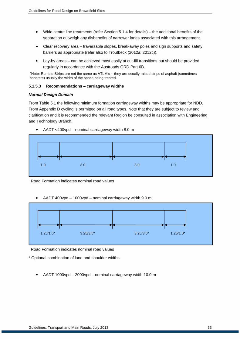
Guidelines for Road Design on Brownfield Sites
Guidelines, Transport and Main Roads, July 2013 33
Wide centre line treatments (refer Section 5.1.4 for details) – the additional benefits of the
separation outweigh any disbenefits of narrower lanes associated with this arrangement.
Clear recovery area – traversable slopes, break-away poles and sign supports and safety
barriers as appropriate (refer also to Troutbeck (2012a; 2012c)).
Lay-by areas – can be achieved most easily at cut-fill transitions but should be provided
regularly in accordance with the Austroads GRD Part 6B.
*Note: Rumble Strips are not the same as ATLM’s – they are usually raised strips of asphalt (sometimes concrete) usually the width of the space being treated.
5.1.5.3 Recommendations – carriageway widths
Normal Design Domain
From Table 5.1 the following minimum formation carriageway widths may be appropriate for NDD.
From Appendix D cycling is permitted on all road types. Note that they are subject to review and
clarification and it is recommended the relevant Region be consulted in association with Engineering
and Technology Branch.
AADT <400vpd – nominal carriageway width 8.0 m
Road Formation indicates nominal road values
AADT 400vpd – 1000vpd – nominal carriageway width 9.0 m
Road Formation indicates nominal road values
* Optional combination of lane and shoulder widths
AADT 1000vpd – 2000vpd – nominal carriageway width 10.0 m
1.25/1.0* 3.25/3.5* 3.25/3.5* 1.25/1.0*
1.0 3.0 3.0 1.0

Guidelines for Road Design on Brownfield Sites
Guidelines, Transport and Main Roads, July 2013 34
Road Formation:
L - Indicates values for low embankments (i.e. <1m) on lower order roads where batter slope
does not exceed 1V:4H
N - Indicates nominal road values
AADT 2000vpd – 4000vpd – nominal carriageway width 11.0 m
Road Formation:
L - Indicates values for low embankments (i.e. <1 m) on lower order roads where batter slope
does not exceed 1V:4H
N - Indicates nominal road values
H - Indicates values on high order roads requiring 1.0m WCLT and 3.25 m lanes
AADT >4000vpd – nominal carriageway width 11.0 m
Road Formation:
L - Indicates values for low embankments (i.e. <1 m) on lower order roads where batter slope
does not exceed 1V:4H
N - Indicates nominal road values
H - Indicates values on high order roads requiring 1.0m WCLT and 3.25 m lanes
2.0 L
2.0 N
2.0 H
3.5 L
3.5 N
3.25 H
-
-
1.0 H #
3.5 L
3.5 N
3.25 H
2.0 L
2.0 N
2.0 H
1.5 L
2.0 N
1.75 H
3.5 N
3.5 N
3.25 H
-
-
1.0 H
3.5 L
3.5 N
3.25 H
1.5 L
2.0 N L
1.75 H
1.0 L
1.5 N
3.5 L
3.5 N
3.5 L
3.5 N
1.0 L
1.5 N

Guidelines for Road Design on Brownfield Sites
Guidelines, Transport and Main Roads, July 2013 35
2.0 m painted median with optional wire rope barriers may be preferred in come situations (12.5 m
nominal carriageway width)
5.1.5.4 Extended Design Domain
On roads where the traffic volume is less than 12,000vpd, and where the existing formation does not
allow for the NDD to be achieved the following minimum formation carriageway widths from Table 5.2
may be appropriate for EDD. From Appendix D cycling is permitted on all road types. Applying EDD
must be in accordance with the requirements of the RPDM 2nd
Edition. As with NDD carriageway
widths, note that they are subject to review and clarification and it is recommended the relevant
Region be consulted in association with Engineering and Technology branch.
AADT <400 – nominal carriageway width 8.0 m
Road Formation indicates nominal road values
AADT 400 – 1000vpd – nominal carriageway width 8.5 m
AADT 1000 – 2000vpd – nominal carriageway width 9.5 m
Road Formation:
L - Indicates values for low embankments (i.e. <1 m) on lower order roads where batter slope
does not exceed 1V:4H
N - Indicates nominal road values
1.0 L
1.25 H
3.5 L
3.5 N
3.5 L
3.5 N
1.0 L
1.25 N
1.0 3.25 3.25 1.0
1.0 3.0 3.0 1.0

Guidelines for Road Design on Brownfield Sites
Guidelines, Transport and Main Roads, July 2013 36
AADT 2000vpd – 4000vpd – nominal carriageway width 10.0 m
Road Formation:
L - Indicates values for low embankments (i.e. <1m) on lower order roads where batter slope
does not exceed 1V:4H
N - Indicates nominal road values
H - Indicates values on high order roads requiring 1.0 m WCLT and 3.25 m lanes
AADT >4000vpd – nominal carriageway width 10.5 m
Road Formation:
L - Indicates values for low embankments (i.e. <1 m) on lower order roads where batter slope
does not exceed 1V:4H
N - Indicates nominal road values
H - Indicates values on high order roads requiring 1.0 m WCLT and 3.25 m lanes
5.1.5.5 Design exceptions
With Design Class B cross-section widening projects, a design exception will occur wherever
proposed values fail to meet the EDD criteria. With Design Class C projects involving improvement of
the seal width, a design exception will occur wherever the proposed values fail to meet the TMR
investment criteria. In all of these cases, the proposal must be justified as described in Section 4.
Some comments on possible approaches are provided below.
Less than 12,000vpd
When retro-fitting an improvement to an existing formation, the most economical arrangement is to
retain the edge line, reduce the width of the through traffic lane and apply a wide centre line treatment.
If the dimensions shown above cannot be achieved, then justification of the arrangement and
appropriate mitigation will be required. Mitigation may include flatter batters (flatter than 1 on 4) and
1.5 L
1.75 N
1.75 H
3.5 L
3.5 N
3.25 H
-
-
1.0
3.5 L
3.5 N
3.25 H
1.5 L
1.75 N
1.75 H
1.0 L
1.5 N
1.5 H
3.5 L
3.5 N
3.25 H
-
-
1.0
3.5 L
3.5 N
3.25 H
1.0 L
1.5 N
1.5 H

Guidelines for Road Design on Brownfield Sites
Guidelines, Transport and Main Roads, July 2013 37
safety barriers (if justified) together with frequent lay-by space – approximate 500 m spacing is
required. Mitigation will also include ATLM located adjacent to the painted centre line. This provides
an additional 200 mm between the ATLM allowing some additional room for movement in the lane
before triggering the audio response from the line. For traffic volumes less than 2000vpd, ATLM may
only be required on the centreline side of the lanes. If run-off-road crashes are prevalent, then the
ATLM will be required on both sides of the lane.
More than 12,000vpd
Duplication of the carriageway is the appropriate solution for roads carrying more than 12,000vpd.
Retention of the two-lane two-way carriageway is therefore a design exception and requires
justification. Appropriate interim solutions (including 2 +1 arrangements) have been discussed above.
In these cases, a minimum carriageway width of 10 m should be available. If widening of the
carriageway is required to retain a two lane arrangement, the additional costs of traffic management
may make construction of a separate carriageway free of traffic an economical proposal thereby
removing the need to have a design exception. If the two lanes are retained, the mitigation measures
will include a wide centre line treatment together with flatter batters and frequent lay-by areas (not less
than 500 m intervals in both directions).
Line marking may include ATLM and be carried out in accordance with the principles shown in
Appendix E. At these traffic volumes, ATLM must be used on both sides of the lane.
5.1.6 Need for formation widening when overlaying
Pavement rehabilitation works that involve a structural overlay will generally require formation
widening in accordance with the following subsection titled ‘Design Criteria when Widening of the
Formation is Required’. Formation widening can be achieved either through steeping batters or by
widening the earthworks footprint.
Occasionally, the existing formation is of sufficient width that formation widening is not required. This
may have occurred because the original formation included a verge treatment and/or wider shoulder to
cater for a future pavement overlay. The following guidance can be used in order to determine
whether the existing formation width is sufficient to cater for the proposed structural overlay.
Unless all of the following criteria are met, the formation is to be widened when providing a structural
pavement overlay:
1. The new carriageway width is at least equal to the greater of:
a. The selected minimum carriageway width, which should equal at least the width of the
majority of the road link (check with the Regional Director, or delegate) plus any curve
widening, manoeuvre widening and verge width requirements. Determination of this
width may well require consideration of the interim seal width for the road link as given
in the TMR document ‘State-Controlled Priority Road Network Investment Guidelines’.
b. If roadway is a principal cycle network, the width required for cycling requirements.
c. 9 m, if on embankment and the batter slopes are steeper than 1 on 4.
2. On low embankments up to 1 m high (desirably 2 m) and in cuttings, the maximum edge slope
of the pavement layers is 1 on 4.
3. On higher embankments, the maximum side slope of the pavement layers is 1 on 2.

Guidelines for Road Design on Brownfield Sites
Guidelines, Transport and Main Roads, July 2013 38
If the above criteria are achieved, the formation does not have to be widened. An example illustrating
this is shown in Figure 5.3. This work type would typically be considered as a Design Class C project.
The above criteria apply even if the width of the carriageway is less than what was previously
provided. Where this occurs, however, ensure lay-bys are provided in accordance with Section 5.1.10.
Where the above criteria cannot be met, formation widening is required in accordance with the
following subsection.
* Maximum side slope of pavement layers:
On low embankments and in cuttings – 1 on 4
On higher embankments – 1 on 2
Figure 5.3: Example indicating where the formation does not need to be widened
5.1.6.1 Design criteria when widening of the formation is required
The criteria given in this section apply when formation widening over a substantial distance is required
(say >500 m). This work type is typically Design Class B.
Unless the cost of construction is prohibitive, the formation should be widened to provide for a Normal
Design Domain carriageway width. A prohibitive cost may result if there are substantial resumptions to
be taken or there are significant services to be relocated. In these cases, an EDD carriageway width
may provide a more economical solution.
Widening to cater for a Normal Design Domain carriageway width has the following major advantages:
1. It is unlikely that the formation will ever need widening again in the foreseeable future (unless
there is a major increase in traffic volume). This results in a low whole-of-life cost solution.
2. If required, it will cater for a nominal future overlay constructed to a lesser width (say an EDD
width).
3. It can often be constructed at the same cost, or lesser cost, than that required providing a
narrower carriageway width. This commonly occurs on embankments because a lesser
amount of widening usually involves ‘sliver’ widening, in which a wider formation has to be
constructed first and then cut-back.
Generally, formation widening on embankment can be undertaken by either steeping batters or by
widening the earthworks footprint. Examples of these, when overlaying, are shown in Figure 5.4 and
Figure 5.5 respectively.
For all instances of formation widening on embankment, the following criteria apply:

Guidelines for Road Design on Brownfield Sites
Guidelines, Transport and Main Roads, July 2013 39
1. On low embankments up to 1 m high (desirably 2 m), the maximum fill slope is desirably 1 on
6 or an absolute maximum of 1 on 4.
2. On higher embankments, the following apply:
a. The maximum fill slope is as per the RPDM and geotechnical considerations.
b. Roadside barriers must be installed if required by the guidance in the RPDM.
The above criteria are applicable at all locations along the embankment, including those at
pipes and culverts.
* Maximum fill slopes:
On low embankments – maximum of 1 on 4 (desirable 1 on 6)
On higher embankments – maximum as per the RPDM and geotechnical considerations
1 Consider using an EDD carriageway width if a Normal Design Domain carriageway width is
prohibitively expensive to construct
Figure 5.4: Example of formation widening on embankment by steepening batters
* Maximum fill slopes:
On low embankments – maximum of 1 on 4 (desirable 1 on 6)
On higher embankments – maximum as per the RPDM and geotechnical considerations

Guidelines for Road Design on Brownfield Sites
Guidelines, Transport and Main Roads, July 2013 40
1 Consider using an EDD carriageway width if a Normal Design Domain carriageway width is
prohibitively expensive to construct
Figure 5.5: Example of formation widening on embankment by widening the earthworks
footprint (widening both sides shown)
Generally, formation widening in cuttings can be undertaken by either steeping batters or by widening
the earthworks footprint. An example of the latter, when overlaying, is shown in Figure 5.6.
For all instances of formation widening in cuttings, the following criteria apply:
1. The desirable maximum slope of the verge is 1 on 6 with an absolute maximum of 1 on 4.
2. The maximum cut slope is as per the RPDM and geotechnical considerations.
Although less desirable for maintenance reasons, an alternative to formation widening in cuts is the
replacement of the open drain with kerb and channel and subsoil drains. This treatment may be
required where property boundary, public utility plant or other limitations apply.
* Maximum verge slope 1 on 4 (1 on 6 desirable)
^ Maximum cut slope as the RPDM and geotechnical considerations
1 Consider using an EDD carriageway width if a Normal Design Domain carriageway width is
prohibitively expensive to construct
Figure 5.6: Example of formation widening in cuttings by widening the earthworks footprint
(widening both sides shown)
In some situations, it can be uneconomical to provide a full pavement/carriageway width on the new
formation as is shown in Figure 5.4 to Figure 5.6. An example of this is on Transport Network
Reconstruction Program (TNRP) projects if there is insufficient complementary funding (TMR funding)
to supplement Natural Disaster Relief and Recovery Arrangements (NDRRA) funding. In these cases,
a narrower pavement/carriageway width can be built on a wider formation as an interim arrangement
as shown in Figure 5.7.

Guidelines for Road Design on Brownfield Sites
Guidelines, Transport and Main Roads, July 2013 41
1 Consider using an EDD carriageway width if a Normal Design Domain carriageway width is
prohibitively expensive to construct
2 The selected carriageway width should be at least equal to the greater of the width of the
majority of the road link and the interim seal width
# Alternative (preferred) treatment
Figure 5.7: Example of providing a narrower pavement/carriageway width when constructing a
wider formation (widening the earthworks footprint on both sides shown)
Some general considerations for formation widening are:
As a general rule sliver widening (cut or fill) should be avoided wherever possible (refer
Section 5.1.7).
The decision about whether to widen on one side or on both sides is site specific and should
be based on economic and technical (safety) considerations. Retaining an offset crown (if
widening on one side only) should be done with caution. Wheel paths on the crown are not
desirable as it can cause some instability in some vehicles (especially those with trailers).
Retaining an offset crown (if widening on one side only) should be done with caution. Wheel
paths on the crown are not desirable as it can cause some instability in some vehicles
(especially those with trailers).
For future width requirements and future upgrades during the design process it is undesirable
to undertake works now that will make future upgrades very difficult (at least without good
reason).
When assessing the most practical form of formation widening, designers should be aware of:
future pavement rehabilitation requirements (and therefore future width requirements)
requirements for edge or median safety barriers
requirements for cycling provision (generally sealed shoulders or bicycle lanes) where works
fall on Principal Cycle Network Routes
the ultimate number of lanes (for high volume roads).

Guidelines for Road Design on Brownfield Sites
Guidelines, Transport and Main Roads, July 2013 42
5.1.7 Sliver widening
This type of work is limited by the standard size of plant. Widening is commonly constructed wider
than the width required and then cut back. From a constructability perspective, it is often not practical
to widen by less than 1.9 m (which equals 2.4 m width of plant minus 0.5 m cutback). Alternatively
smaller less efficient equipment may be used to construct a narrower widening in the first instance.
Although this adds to the construction cost, it may be necessary to maintain clearances to property
boundaries, services or to fit in with existing lengths of culverts, lengthened culverts or bridge widths
etc. However, constructability implications of formation widening may not apply with flatter batters
(typically 1 on 4 or flatter) as machinery can work longitudinally along the slope of the batter or
transversely on the batter. In urban areas widenings between 1.2 m and 1.9 m are more practical due
to surrounding constraints and use of pedestrian path rollers.
5.1.8 Single or both sides widening
For a crowned two-lane, two-way road, symmetrical widening on both sides of the pavement means
that the crown does not normally move (i.e. stays in the centre of the pavement). When widening on a
single side of the pavement, it is desirable to shift the crown to the centre of the new carriageway
(rather than have an offset crown in the finished works). This can be achieved by:
reforming all pavement layers to reinstate the crown
Reinstate the crown in the correct location using overlay only. The designer will need to
ensure that the required thickness of overlay covers the former crown location. This will also
mean that the overlay thickness will be greater elsewhere across the pavement formation.
Single sided widening may be considered when site specific issues make it difficult to widen on both
sides. Site specific issues may include:
a longitudinal watercourse located close to the carriageway on one side
if culvert widening is not preferred the maximum slope is the vicinity of the culvert should be
limited to 1 on 3 and shoulders are to be sealed for protection
desire to align the road to fit adjacent intersections; this may also apply when new turning
lanes are planned, or
when adjacent to horizontal curves widen the tangent on one side when improvements are
made to the curve i.e. improving curve radii or installing transitions.
5.1.9 Fill batter slopes
It is common practice to increase the slope of fill batters to accommodate pavement widening.
However on fills heights up to 1 metre (desirably 2 metres), this should only be considered if the
reconstructed batter slope is limited to 1 on 4 (desirably 1 on 6). This guidance should be applied to all
projects where there is a potential for fill batter slopes to increase.
Providing a steeper batter slope has the following problems:
it is more difficult for drivers or riders to recover on steeper batter slopes (Safety)
they more commonly experience water infiltration issues (Pavement durability)
It is more difficult to mow steeper batters particularly near guardrail. Unmaintained batters are
unsightly and can cause issues with animals living closer to the road and issues with
vegetation blocking visibility (to intersections and around horizontal curves) (Maintenance)

Guidelines for Road Design on Brownfield Sites
Guidelines, Transport and Main Roads, July 2013 43
there is also a greater need for batter protection on steeper batters.
Generally higher fills (ie greater than 2 m) typically have batter slopes 1 on 2. Roadside safety barriers
are to be used on these fills in accordance with the RPDM 1st Edition Chapter 8.
This guidance should be applied to all projects where there is a potential for fill batter slopes to
increase.
5.1.10 Lay-bys
Formal roadside stopping places are provided in accordance with the RPDM 1st Edition Chapter 20. In
addition, it is necessary to ensure that there are frequent opportunities for discretionary stops
completely clear of the road when the shoulder is 1.5 m or less (maximum spacing 1 km, maximum
slope 1 on 10). These ‘lay-bys’ can be provided by flattening batter slopes on low fills or making
provision at the transition of cut and fill and do not have to be paved or sealed. Construction of new
areas is not required where there are existing opportunities stop completely clear of the road, such as
the following:
widened shoulders at low volume intersections and accesses
school bus stops
wide shoulders, parking lanes or side streets in townships
widenings at bridge approaches
formal stopping places as described in the RPDM 1st Edition Chapter 20.
It is especially important to consider lay-bys in 'guardrail canyons'.
5.1.11 Verge
The verge can be made equal to zero under well defined circumstances:
batters slopes are 1 on 4 (4H:1V) or flatter, or
barriers are not needed now or anticipated within 20 years, and
sealing is extended to the hinge point to protect against natural rounding, and
batters are quickly grassed / vegetated to protect against erosion.
Refer also to Troutbeck (2012a; 2012c) for acceptable treatment of barriers in restricted situations.
Many existing roads in Queensland have no verge and were not designed with a verge. Some of these
will have experienced “natural” rounding or rounding developed over years of maintenance grading
with a net loss in shoulder width. Where pavement rehabilitation works are to be carried out, the
remaining formation width should be closely examined to determine the potential for improvement by
reshaping or widening or both, keeping in mind the relative benefits of the various combinations of
shoulder and pavement width.
An important input into these considerations will be the crash rate on these types of roads and over
the full length of the link in question. Note that consideration of the specific section of road under
design alone is not sufficient, given the random occurrence of crashes on the road system. Of course,
a concentration of run-off-road crashes in the vicinity will be a strong indication of the need to remedy
the situation.

Guidelines for Road Design on Brownfield Sites
Guidelines, Transport and Main Roads, July 2013 44
5.1.11.1 Mitigation
The following possibilities need to be considered both individually and in combination, depending on
the particular circumstances at the site in question:
formation widening and reshaping with flatter batters
clearance of a clear zone for at least 5 m, preferably 9 m depending on the practicality of such
action and ensuring that the whole clear zone is traversable (e.g. no ditches and no batters
steeper than 1 on 4), and
installation of safety barrier at the hinge point (refer Troutbeck 2012a; 2012c).
Sealing shoulders full width is essential in all cases.
5.1.12 Clear Zone
The Clear Zone concept is well described in TMR practices and policies as described in the RPDM
2nd Edition. Figure 8.4 of Chapter 8 of the RPDM 1st Edition lists the recommended clear zone widths.
Figure 5.8 illustrates an example of clear zone design from the Austroads GRD Part 6. Note that the
shoulder includes the clear zone calculation and any non-recoverable slope is excluded. The RPDM
2nd Edition should be consulted for further guidance.
In Commentary 3 of the Austroads GRD Part 6 (page 269), it states:
The selected clear zone width is a compromise, based on engineering judgement, between
what can practically be built and the degree of protection afforded the motorist (NYS DOT
2003). In applying engineering judgement it is essential to properly account for the specific
characteristics and risks associated with particular sites. For example, a deep continuous precipice
just beyond the clear zone on a high-volume, high-speed road would require shielding because of the
high exposure and severity whereas an isolated point hazard just within the clear zone of a low-
volume road may be judged not to require treatment.
On some projects it may be appropriate to define a single clear zone width for the entire length of the
project. However, during the feasibility and detail design stages it is desirable that the widths be varied
in a step-wise fashion to take account of site factors and in accordance with the widths that can be
reasonably achieved.
(Bolding added by DTMR)
It will be clear from a reading of Austroads GRD Part 6 that the clear zone width is not a fixed value –
it varies with the space available and the physical constraints applying at the site in question. The
degree of possible recovery in the available clear zone may be assessed from the information
available in the RPDM 2nd Edition and appropriate decisions made on the need for more or less clear
zone or for required treatments where sufficient clear zone does not exist. The customary clear zone
values have been in the vicinity of 9.0 m but lesser distances still provide some advantage. For
example a 6.0 m clear zone on an un-divided road potentially allows for 70 to 80 percent of vehicles to
avoid colliding with the hazard.
Particular attention should be given to the conditions near the boundary of the clear zone. If a sever
hazard exists just outside the clear zone (e.g. major ravine or solid continuous obstruction), then
measures will be required to prevent a vehicle impacting that hazard. Conversely, an isolated hazard
just inside the clear zone may be assessed as having a low likelihood of being impacted and therefore
minor mitigation measures may be all that is required.

Guidelines for Road Design on Brownfield Sites
Guidelines, Transport and Main Roads, July 2013 45
Figure 5.8: Example of a parallel fill slope design illustrating clear zone and slopes
(Source: Austroads GRD Part 6, Section 4.3.5 and Table 4.1, note 2)
On existing roads, it is clearly the case that the clear zone achievable has to be a compromise
between the competing demands:
safety (the RISC software may be of assistance in analysing individual cases)
environmental issues (in many rural areas, the road reserve provides the last remaining
examples of the natural vegetation and it has a high conservation value)
right-of-way available
existing earthworks, and
cost.
Levett (2007) provides analysis of NSW data for crashes into trees and demonstrates that up to 75%
to 85% of the safety benefits of the clear zone are captured in the first 5 to 6m of the clear zone (i.e.
reduced number of crashes and reduced severity of crashes). The data does confirm previous studies
both in Australia and USA that the provision of a narrower clear zone of 5 to 6 m will achieve

Guidelines for Road Design on Brownfield Sites
Guidelines, Transport and Main Roads, July 2013 46
considerable advantages and that most crashes occur within 10 m of the edge line. This also confirms
the guidance given in the RPDM 2nd
Edition and Austroads GRD but indicates that achieving 5 to 6 m
of clear zone may be an effective compromise where constraints occur.
Where the required clear zone cannot be achieved, then it is necessary to examine the features that
occur in that zone to determine the best treatment needed to minimise crashes and the severity of
those crashes.
Figure 5.10 illustrates an approach to treatment on horizontal curves.
Figure 5.9: Clear zone transition on approach to horizontal curves
(Source: Austroads GRD Part 6)
Mitigation
Where the full clear zone defined in RPDM 2nd Edition and Austroads GRD Part 6 cannot be achieved
the following should be considered for mitigation:
5 to 6 m from the edge line kept clear of: rigid objects; slopes steeper than 1 on 6, and ditches
individual poles and sign supports made frangible
crash cushions used for isolated hazards
safety barrier used on the roadside to shield hazards that cannot be removed or made
frangible
Audio Tactile Line Marking and/or rumble strips to assist in fatigue related crash prevention.

Guidelines for Road Design on Brownfield Sites
Guidelines, Transport and Main Roads, July 2013 47
5.1.13 Installation of safety barriers
Austroads (2010c page 73) GRD Part 6 Section 6.3.4 states:
The lateral position of a barrier is influenced by the:
road cross-section (e.g. need for shoulder and/or kerb)
barrier-to-hazard clearance
trajectory of vehicles when crossing kerbs and slopes
desire to avoid nuisance damage.
Figure 6.2 of the Austroads GRD Part 6 shows a typical lateral location of a barrier in the verge of a
road. It shows that the position of the barrier may be dependent on the:
offset to travel lane
system width
support width.
Desirably, barriers should be located away from the hinge point so that, while the barrier deflects, the
errant vehicle will still be on the verge.
Generally higher W-Beam barrier is better (at containing errant vehicles) than lower W-Beam barrier.
Additionally higher barriers are better at retaining heavy vehicles. If barrier is lower than 710 mm
(desirably not lower than 726 mm) to the top of the rail, it should be lifted.
Obtaining correct barrier heights on known motorcycle routes will enable easier retrofitting of rub-rail at
lower cost in future if required.
5.1.13.1 Locating barriers on the hinge point
On existing roads where the offset to the traffic lane is restricted, it is possible to place the barrier at
the hinge point. This will generally involve the use of longer posts or other treatments to ensure that
there is sufficient support for the barrier system. The RPDM 2nd Edition allows for W-beam barrier to
be placed at the hinge point so long as longer posts are used; the length of the post being determined
by the embankment slope beyond the hinge point. (DTMR standard Drawing, SD1474F, also shows
post configuration and dimensions when the barrier is installed 650mm in front of the hinge point.)
Wire rope barriers are proprietary products and their use in different configurations to their full scale
tests, should be done so with the approval of the manufacturer. Nevertheless there is evidence as
outlined in Troutbeck (2012 a) that these barriers could be placed at the hinge point under Extended
Design Domain based on a well documented and substantiated risk management case. Similarly,
proprietary W-beam systems could be used under EDD with similar requirements for documentation
and approval by the developers and manufacturers.
Maintenance of the barrier and the area behind the barrier may be difficult and appropriate
maintenance procedures should be considered and documented as part of the installation
requirements under EDD. Provision should be made for repairs of wire rope barrier installations to be
made quickly should even a minor incident occur.
The anchorages for EDD wire rope systems must be constructed in accordance with the Normal
Design Domain systems and designed to suit the ground conditions. The verge in which the

Guidelines for Road Design on Brownfield Sites
Guidelines, Transport and Main Roads, July 2013 48
anchorage is installed must be widened to accommodate the anchorage in the usual design and this
may require a longer length of wire rope barrier to be installed.
The design deflections should be increased above those typically used for barriers installed some
distance from the hinge point. When barriers are installed at the hinge point, the deflection will be a
function of the lateral restraint of the posts. If by chance one post does not supply the required lateral
restraint then the deflection will be increased. Consequently it is recommended that the design
deflections be increased above the deflections recorded in the full scale tests as an additional factor of
safety. An arbitrary increase of 20 per cent is suggested. A fixed hazard like a tree or a pole should
not be within the design deflection.
Only wire ropes barriers with four ropes can be installed at the hinge point when the horizontal curve
radius is greater than 800 m. Three ropes systems should not be used and barriers should not be
installed when the horizontal radius is less than 800 m. The mounting heights of the cables are
measured from the ground surface at the posts.
Refer to Troutbeck (2012a) for more detail.
5.1.13.2 Locating barriers on embankments steeper than 1 on 10
Section 8.2.2.3 in Chapter 8 of the RPDM 1st Edition has the following statement about barriers in
close proximity to batters:
Similar to crashes involving kerbing, a wide range of factors will influence the behaviour and trajectory
of errant vehicles as they transverse batters (e.g. suspension stiffness, vehicle weight, speed of
impact, angle of impact).
Consequently there is uncertainty about where to position barriers so that:
The vehicle does not vault over the barrier; or
The vehicle does not go under the barriers with consequent snagging on barrier supports and
other problems.
This uncertainty makes it difficult to position barriers on batters such that their operation is assured.
With this statement in mind, barriers should only be installed on embankments under a design
exception.
The performance of a barrier system is based on the foundations or the footings, the effective height
of the barrier and the likely interaction of the vehicle with the barrier.
The effectiveness of post foundations should be assessed with full-scale testing or designed with
reference to full-scale test results. The foundations of barriers installed on embankment slopes should
have the same or higher strength as those systems installed on level ground. The strength of the
foundations must be evaluated and documented.
A barrier, installed on an embankment slope, must be able to accommodate impacts at a broader
range of impact heights than would be expected if the barrier were to be installed on the verge.
Otherwise, there is a significant risk that vehicles will overtop, or under-ride the barrier.
There will always be a greater propensity for vehicles to roll over on embankments and it is important
that the effective height is maintained. The propensity, for vehicles to roll over, increases on steeper
embankments.

Guidelines for Road Design on Brownfield Sites
Guidelines, Transport and Main Roads, July 2013 49
Vehicles engage with different barriers in different ways. For instance the wire ropes cut into the
vehicle’s body work: too low and the vehicle rides over them; and too high and the ropes ride over the
bonnet and are ineffective.
For a design exception it is important to indicate how the proposed barrier vehicle interface will assist
the barrier to redirect vehicles.
Within an EDD and design exception report, the likely range of impact heights should be
identified and documentation to show how the range is being addressed, including the how the
vehicle will interact with the barrier, must be produced.
Terminals are critical parts of a barrier system. They need to provide the necessary restraint when
a vehicle impacts close to the end and they need to be crashworthy in their own right. Terminals
should not be constructed on an embankment fill slope. In general, it would be difficult to justify a
design exception for terminals on embankments and an EDD and design exception report must justify
that the proposed location does not compromise the operation of the terminal.
Barriers on embankment slopes may be of use on roads with very high cycle usage to allow the
shoulder to be more effectively used by cyclists.
In most cases, barriers installed on embankment hinge points would provide a better solution even if
the barrier is within the shy line distance. This would cause vehicles to travel closer to the centre line
of the road and perhaps slower. The decision not to install barriers on the hinge point should be
evaluated and documented.
5.1.13.3 Mitigating issues
Some of the issues with the use of barriers on embankments are mitigated if the traffic speeds are
lower, the likely impact angles are smaller and the embankment slopes are flatter.
Refer to Troutbeck (2012c) for more information.
5.1.13.4 Installation of wire barriers in narrow medians
Wire rope barriers in narrow medians are an effective road safety measure.
They significantly reduce the number of fatalities and casualty accidents. There is a small risk that a
vehicle might be arrested in the opposing lane and this may create an additional risk. The use of wire
rope barriers in narrow medians is considered to be part of the EDD.
The effectiveness of the traffic operations on roads with median barriers needs to be evaluated and
documented. This includes consideration of future traffic operation scenarios. Steep grades and the
inability to overtake will affect the traffic operations significantly. The RPDM restrictions for installing
wire rope barriers on vertical and horizontal cures should not be relaxed when installed in narrow
medians.
The access to properties and minor roads and the means to enable vehicles to make u-turns needs to
be evaluated and documented.
The wider the median the better and installation of wire rope barriers in medians narrower than 1.5 m
should not occur until further research is undertaken to justify this. Justification for the median width
needs to be documented.
The performance of wire rope barriers depends on the number of ropes, the post spacing, the initial
tension in the ropes, the distance between anchors and whether the ropes are interlaced or not.

Guidelines for Road Design on Brownfield Sites
Guidelines, Transport and Main Roads, July 2013 50
It is recommended that only four rope systems be used and that these can be either TL3 or TL4
systems. The choice should be based on traffic composition and volumes. Posts should be spaced at
2.5 m or less to limit deflections. Preference should be given to the systems that use higher cable
tensions.
The proprietary product, type and performance characteristics should be carefully evaluated and
documented. Not all brands are equally effective in narrow medians even though they have the same
test level rating.
The expected impact rates should be investigated and documented.
Wire rope barriers have not been designed to arrest or redirect heavy articulated vehicles. A risk
assessment on the likelihood and outcome of heavy vehicles colliding with the barrier should be
evaluated. Note that the presence of a number of heavy vehicles using the road does not preclude the
use of wire rope barriers in the median.
The end treatments used in wire rope barriers perform quite differently. Terminals that limit the
chances of causing a vehicle to roll over are preferred. The implications of an impact on the terminal
releasing the tension in the cables should be evaluated. The location and installation details of a
terminal should be to minimise the likelihood of vehicles impacts.
The length of horizontal curves, the crossfall and super-elevation, the location of the crown are issues
that may affect the performance of the road or barrier. These aspects should be evaluated and
documented.
Refer to Troutbeck (2012b) for more information
5.1.13.5 Use of lower permanent concrete barriers
Permanent single slope barriers that are 920 mm high meet the testing requirements under MASH
TL4. In contrast, New Jersey barriers that are 820 mm high failed MASH testing (AASHTO 2009) even
though they were considered to be suitable under NCHRP 350. (Ross et al 1993) The constant slope
820 mm barrier meets NCHRP 350 requirements.
Present single slope barriers that are 1100 mm high provide greater protection and should be used
where possible. However lower barriers could be used, as a design exception, to assist with
maintaining appropriate sight distances. The evaluation of their installation should consider whether
TL4 barriers are justified and whether other barriers types would be effective. The evaluation should
also consider the increased risk due to more severe impacts if the road horizontal radius is less than
600 m.
Refer to Arndt et al (2011) and Troutbeck (2012d) for more information.
5.1.13.6 Protection of a hazard close to the road
A W-beam can be stiffened with decreased post spacings and perhaps the nesting of two rails to
reduce the deflection if a hazard is close to the road. For W-beam systems the stiffness can be
increased to that approaching a rigid barrier. For wire rope barriers, the deflection can also be reduced
through reduced post spacings. In some circumstances the design deflection of a wire rope barrier
may not be able to be reduced to the available space between the barrier and the hazard.
Given that the design deflection is the deflection recorded in a full scale test and that all of the
conditions of the full scale test are expected to be exceeded once in about 900 impacts, then a
reduced distance between the hazard and the barrier could be acceptable, based on a risk

Guidelines for Road Design on Brownfield Sites
Guidelines, Transport and Main Roads, July 2013 51
assessment in an EDD and design exception report. The assessment would need to consider the road
type, the road geometry, cross section, the dimensions of the hazard, and available space for the
barrier to deflect.
Refer to Burbridge and Troutbeck (2012).
5.1.14 Overtaking lanes and climbing lanes
Chapter 15 of the RPDM 1st Edition provides the DTMR approach to overtaking lanes in brownfield
sites. Note that such lanes should not be started or ended on horizontal or vertical curves. The full
development of the widened section should be completed at least 50 m before the tangent point of any
curve and the widened section should be continued for 50 m past the tangent point on the exit to the
curve.
Further consideration could be given to allowing existing formation widths to be used by reducing the
shoulder width over the length of the overtaking lane or climbing lane to 0.5 m (sealed). Additional
space may be obtained by reducing the width of the overtaking lane itself to as low as 3.0 m, retaining
the acceptable width for the through lane. The traffic lane in the opposing direction should be the
acceptable width for the conditions and may be modified if the adjacent shoulder is sealed for a
minimum width of 1.0 m. The acceptable width of lane depends on the type of heavy vehicle using the
road and the total traffic volume.
Table 5.6 sets out possible carriageway widths for different road classes and traffic volumes for
restricted situations using these principles. It has been developed on the basis of the acceptable
widths suggested by the National Transport Commission Network Classification Guidelines but must
be regarded as a design exception. Approval to adopt the reduced lane and shoulder widths will be
required.
Table 5.6: Examples of Carriageway widths (Design Exceptions) for passing lane sections
(existing formations)
Road Class (1) AADT Carriageway (m) (3,4)
L2 (2)
400 – 1000 0.5 + 3.0(6) + 3.1 | 3.1 +1.0 = 10.7
1000 – 4000 0.5 + 3.0(6) + 3.2 | 3.2 + 1.0 = 10.9
>4000(5) 0.5 + 3.0 + 3.0 |1.0| 3.0 + 1.0 = 11.5
L3
400 – 1000 0.5 + 3.0(6) + 3.2 | 3.2 + 1.0 = 10.9
1000 – 4000 0.5 + 3.0(6) + 3.2 | 3.3 + 1.0 = 11.0
>4000(5) 0.5 + 3.0 + 3.0 |1.0| 3.0 + 1.0 = 11.5
L4
400 – 1000 0.5 + 3.0(6) + 3.2 | 3.3 + 1.0 = 11.0
1000 – 4000(5) 0.5 + 3.0 + 3.0 |1.0| 3.0 + 1.0 = 11.5
>4000(5) 0.5 + 3.0 + 3.0 |1.0| 3.0 + 1.5 = 12.0
Notes:
1. Adapted from the National Transport Commission PBS Scheme – Network Classification
Guidelines.
2. Definitions of access levels are shown in Table 5.7
3. Assumes all shoulders are fully sealed.
4. Mitigation will be required to minimise run-off-road and head-on crashes.

Guidelines for Road Design on Brownfield Sites
Guidelines, Transport and Main Roads, July 2013 52
5. It is preferable to adopt 3.0 m lanes for the two opposing lanes and insert a 1.0 m painted
median (|1.0|).
6. As this lane accommodates trucks, it may be preferable to adopt the wider lane dimension and
use the narrower lane for the other one. However, if this is a climbing lane where the speed of
trucks will be low, the narrower lane would suffice.
Note that these dimensions do not take account of the adjacent batter slope, the location of road edge
guide posts, bicycle requirements or the need for safety barrier. Additional width will be required to
accommodate road edge guide posts, bicycles and safety barrier.
Table 5.7: Definitions of Access Levels
Road Class Scheme Vehicle Level Vehicle Description
Level 1 access (L1) 1 From passenger cars to single articulated
Level 2 access (L2) 2 B-double
Level 3 access (L3) 3 Double road train (Type 1)
Level 4 access (L4) 4 Triple road train (Type 2)
(refer National Transport Commission PBS Scheme)
5.1.14.1 Mitigation
Similar mitigation strategies to those for narrower lanes should be considered. Mitigation in a particular
circumstance may include some or all of the following:
batters of 1 on 4 or flatter adjacent to the shoulder (critical for 0.5 m shoulders)
Audio Tactile Line Marking;
wider lane lines
raised pavement markers
rumble strips on the shoulder
centreline rumble strips
1.0 m wide centre line treatment or painted median with ATLM
clear zone of 5 m or greater.
5.1.15 Floodways
Width Range
The floodway formation width should be the same as the approach formation with a minimum of 8.0 m
on existing low trafficked roads (< 150vpd) with appropriate approval for such a width.
Safety Barriers/Bridge Rails
Safety barrier will reduce the efficiency of the floodway in times of flood, but may be desirable from the
point of view of traffic safety at other times. Whether safety barrier should be installed in a particular
case should be determined locally, but where associated with a bridge structure:
when the bridge is full floodway width, and the main channel is shallow, consideration should
be given to omitting bridge rails and safety barrier. However, road edge guide posts may be
provided on the floodway with refectories hazard markers at the bridge abutment;

Guidelines for Road Design on Brownfield Sites
Guidelines, Transport and Main Roads, July 2013 53
when the bridge is narrower than the floodway or the channel is deep it may be desirable to
use rails with at least the minimum length of safety barrier on the floodway approach to the
bridge. The conflict of goals i.e. delineation as against obstruction in flood time cannot be
determined by a general policy but must be decided locally by consideration of the specific
case.
When considering whether to retain an existing floodway or not, the following should be considered:
Comfort of the vertical alignment in dry conditions (the minimum requirements for vertical
acceleration defined in the RPDM 2nd
Edition should be achieved);
Available sight distance to the water surface in wet conditions (EDD stopping distance should
be the minimum that is be tolerated);
Flood immunity available on the remainder of the link (time of inundation should be considered
as well as the level of immunity achieved – refer also to the RDM);
Surface condition of the floodway itself (if the riding quality of the pavement and/or its
structural strength are inadequate, then the pavement should be replaced and if this occurs,
the value of retaining the asset will be substantially removed);
Width of the floodway (compared with the approaches). If the width is less than that of the
approach roadway, its acceptability could be assessed in a similar manner to that for narrow
bridges.
An overriding consideration will be the substantive safety of the site, as measured by the actual crash
rate and by assessing the safety using the ARRB Road Safety Risk Manager. If crashes are directly
associated with the floodway presence or the Risk Manager shows a high risk, then the acceptability
of retaining the floodway will be substantially reduced.
Given that the safety risk analysis does not preclude the retention of the floodway, then mitigation
strategies to assist in keeping the floodway “safe” will need to be adopted.
5.1.15.1 Width of floodway
The acceptable width will depend on the traffic volumes and types of heavy vehicles using the road.
For roads with AADT less than 150vpd, then the RPDM 2nd
Edition values should be adopted (i.e.
minimum width of 8 m). For other roads, the minimum width should be the width of the approach traffic
lanes plus shoulders of 1.0 m. Where this width is less than the total carriageway width of the
approach road, it is a design exception and mitigation will be necessary.
5.1.15.2 Mitigation
For less than desirable vertical acceleration (i.e. greater than 0.05g), the warning sign “Dip”
must be used in conjunction with an advisory speed sign in advance of the floodway and after
the warning sign “Floodway”. This signage is in addition to the usual “Road Subject to
Flooding – Indicators show depth” placed in advance of the relevant section of road.
The advisory speed sign used in association with the “Dip” sign can also function as the
warning for any deficiency in sight distance to the water surface.
For narrow short floodways, the approach warning signs are described in the MUTCD and
these requirements must be followed.

Guidelines for Road Design on Brownfield Sites
Guidelines, Transport and Main Roads, July 2013 54
For long floodways, consideration should be given to providing pull-off areas at not more than
500 m spacing (refer to Austroads GRD Part 6B for details of suitable stopping places).
5.2 Sealing unsealed pavements
Sealing an existing unsealed road will lead to significant increases in operating speed on the
road involved and it will be essential to carry out a geometric assessment of the road before
proceeding with that solution.
Improvements to the alignment will need to be considered where the existing geometry does not meet
the requirements for the revised operating speed. (Refer to Volume 1 of the RPDM 2nd
Edition for
discussion of design classes and the requirements for unsealed roads.)
While EDD may be applied in these circumstances, it is unlikely that design exceptions would be any
more acceptable than on other roads just because of low traffic volumes. Consideration of the costs of
the alternatives is essential to be able to justify adopting the lower values for design elements. The
following issues should be considered:
potential change in the traffic composition (e.g. will the improvements in the route attract
significant additional traffic including heavy vehicles?)
potential increase in total traffic volumes above the normal growth rate
increase in operating speed
extent of additional pavement required on the existing alignment and its cost;
difference in traffic control costs between working on the existing alignment and a new
alignment (where the new alignment is the alternative), and
difference in cost between adopting NDD, EDD and any design exceptions judged to be
acceptable together with the mitigation strategies required.
The same principles developed elsewhere in these Guidelines should be applied, including any
mitigation strategies required.
5.3 Crest curves
5.3.1 Overview
Austroads GRD Part 3 Appendix A provides details on the development of EDD values based on the
analysis of Stopping Sight Distance and crest vertical curves. These values are predicated on using
less conservative values for some of the input parameters used in the calculations.
In cases where the existing alignment does not meet these EDD values and a lower K value for
the crest exists, retention of this crest is a design exception.
Such exceptions may be able to be justified in some circumstances. The amount of justification
depends upon the relevant design class as explained in section 3.3 of Volume 1 of the RPDM 2nd
Edition. Design class set TMR expectations with respect to the relevant design criteria (including the
use of EDD and design exceptions).
Section 4 shows the appropriate process to be used to undertake a justification for adopting such an
exception (refer in particular to Figure 4.1).

Guidelines for Road Design on Brownfield Sites
Guidelines, Transport and Main Roads, July 2013 55
5.3.2 Developing alternatives
Depending upon the project design class and the magnitude of the design exception, alternatives
including one that meets NDD standards will need to be developed and evaluated in accordance with
the process in Section 4.2. Alternatives should include:
retain the existing geometry
adopt NDD requirements, and
adopt EDD requirements.
These will require sufficient design to allow reasonable estimates of cost to be developed and the
impacts to be assessed. It is not sufficient to assume that retention of the existing is the only solution
that needs to be evaluated.
Oxley et al (2004, page 21), Kirkpatrick et al (2000), Cox (2003), and Austroads (2010a pages 19-20)
give details of a number of studies to try and establish a clear relationship between accident frequency
and sight distance restrictions on crests. However, these studies were unable to establish any clear
relationships. At best, the studies established:
Even on limited sight distance roadways, limited stopping sight distance is not a major
problem.
Most of the objects struck on roadways with limited sight distance vertical curves were large
objects such as animals and other vehicles.
Given the option, drivers will more often avoid a hazard on the road rather than stop for it.
All crashes with limited stopping sight distance as a possible contributing factor occurred on
vertical curves with K values of 38 m or less. Additionally, most of the crashes with limited
stopping, sight distance as possible contributing factor occurred on vertical curves with K
values of 30 or less.
For roads with a speed limit of 80 km/h or 90 km/h, the minimum sight distance for ‘safe’
operations on crests is between 95 and 110 m. This equates to about 3.5s to 4s of travel at
the 85th percentile speed (applied between car driver eye height and a small hazard) and
provided there are no accesses or intersections with limited sight distance.
The preceding findings underpin the risk ratios established in Austroads (2010a) and included in
5.3.3.5. The preceding findings also allow sub-standard crests to be examined to establish whether
there is useful sight distance capability that may help justify retention.
Parameters to be examined include:
perception reaction time – 1.5secs may be appropriate, but may need some mitigation to
increase alertness
manoeuvre time – assume 2.0secs for cars and 2.5secs for trucks plus the perception reaction
time
height of object – it may be possible to make an assessment of the likelihood of particular
obstructions being present (e.g. falling rocks, dead animals) but in all cases, the largest object
that can be considered is that of a car stopped in the traffic lane (h = 1.25 m)

Guidelines for Road Design on Brownfield Sites
Guidelines, Transport and Main Roads, July 2013 56
carriageway width – there must be enough space to allow an approaching driver to
manoeuvre around the stopped vehicle – shoulder widths of 2.5 m are required with batter
slopes of 1 on 4 or flatter
clear zone – 5 m minimum clear zone is required (9 m preferred), and
providing a surface with increased friction resistance (maintenance measures will be required
to ensure that this is retained in the long term).
Table 5.8 shows how a situation may be analysed for manoeuvre capability for the appropriate 85th
percentile speed. Other situations may also be analysed (e.g. buses [eye height 1.8 m]). This table
shows the capability achieved for the worst case scenarios yielded by the above parameters, bearing
in mind that more conservative values may be more appropriate for some parameters in a particular
case (e.g. because of a coincident horizontal curve or the proximity of an intersection).
Consequently, Table 5.8 identifies a limit below which is no useful sight distance capability exists for
the 85th percentile speed and the lower limit for where supplementary manoeuvre width would be a
useful mitigating treatment to help justify a design exception.
Table 5.8: Manoeuvre distances and K values – potential justification for design exceptions
V
(km/h)
RT
(sec)
Manoeuvre Time
(sec)
Sight Distance
(m)
K1
Car Truck Car Truck Car Truck
80 1.5 2.0 2.5 78 89 6.5 6.6
90 1.5 2.0 2.5 88 100 8.25 8.4
100 1.5 2.0 2.5 97 111 10.02 10.3
110 1.5 2.0 2.5 107 122 15.85 12.46
Note¹: Car: Eye height = 1.1 m, Object height 1.25 m
Truck: Eye height = 2.4 m, Object height 0.8 m
Retaining these types of crests will require appropriate mitigation measures, including speed control
as described in Section 5.3.4. None of these would be acceptable if the site has a history of crashes.
Using an eye height of 1.1 m combined with an object height of 0.8 m for cars is preferred and would
produce crest curves of K11.95 (95 m) and K16 (110 m) for these sight distances and these values
should be adopted if possible.
Austroads (2010a page 20) provides further commentary on research into the relationship between
crash rates and sight distance restrictions (See 5.3.3.5). It concludes that:
A number of authors have commented on the value of crest flattening projects to retrofit sight distance
improvements (e.g. Mullin 1972, Glennon 1987b). The common view is that crest flattening will
generally not be a cost-effective means of reducing crash risk. Practical constraints from topography
will usually limit the improvement to a relatively modest increment of sight distance, and the new crest
will be longer giving increased exposure.
If the existing road with posted speed equal to or greater than 90 km/h has K values of crest curves
providing SSD less than 90 m, then they should be upgraded to at least EDD standard. If this is not
possible, then a design exception exists and it must be justified. In some circumstances, it may be

Guidelines for Road Design on Brownfield Sites
Guidelines, Transport and Main Roads, July 2013 57
suitable to introduce a lower speed limit, provided it is credible to drivers. This may require speed
environment measures to be implemented.
5.3.3 Evaluation
Evaluation in accordance with Section 4.2.3 will be required.
5.3.3.1 Combined geometric features
The presence of horizontal curves, property accesses, intersections and narrow carriageway
singly or in any combination affects the ability to retain a sub-standard crest curve.
A horizontal curve of radius less than 600 m in conjunction with the sub-standard crest adds
considerably to the driving task and may affect the ability of drivers to undertake suitable manoeuvring
actions to avoid objects (including stopped vehicles) in their path. In general, a design exception crest
curve should not be associated with a horizontal curve less than 600 m in radius. If the horizontal
curve starts beyond the crest on the vertical curve, then the situation is not tolerable at all.
Property accesses and intersections located on or beyond the crest curve also make the situation
intolerable when it is not possible to achieve at least EDD sight distance capability for the respective
situation. The likelihood of crashes at such locations will be increased if they are retained. Over the
long term, it can be expected that such locations will generate crashes even if the recent past has not
produced such crashes. Note that there are situations where suitable sight distance can be achieved
for an access or intersection located on top of a sub-standard crest. However, the suitability of the
crest will still depend on the sight distance capability at other points on or beyond the crest.
A narrow carriageway allows no room for manoeuvre to occur if a driver is confronted with an obstacle
in the road just over the crest. Without treatment of the width available, retention of the design
exception will be difficult.
Austroads GRD Part 3 Appendix A addresses factors to be considered in the combination of horizontal
and vertical alignment with width of carriageway when considering EDD.
5.3.3.2 Length of the design exception
Is this an isolated curve or one of a series of sub-standard curves? An isolated curve may not impose
an unacceptable cost on the project if it is upgraded to at least EDD requirements. A series of such
curves would be costly to improve and consideration of reduction of the posted speed limit would be
reasonable. Mitigation measures over the whole length would be required in order to make the need
for the reduced speed limit apparent to the drivers.
5.3.3.3 Duration of the design exception
If this is a long term proposal for the road, then the level of mitigation required will be
substantial. Comparison of the costs of retention of the exception plus mitigation with the cost
of upgrading must be carried out to justify the decision.
5.3.3.4 Location with respect to other risk factors
Other features such as the location of narrow drainage structures, bridges and floodways close to the
extremities of the crest will have an effect on the suitability of the retention of the exception. Such
features require good visibility and if the crest prevents adequate visibility, it creates an unacceptable
situation.

Guidelines for Road Design on Brownfield Sites
Guidelines, Transport and Main Roads, July 2013 58
The location of roadside furniture and/or trees also has to be considered and action to address these
features will be required.
5.3.3.5 Substantive safety at the site
The types of crashes that may be associated with a sub-standard crest include:
rear end crashes on the crest curve
run-off-road crashes on or near the crest curve
collisions at accesses or intersections on or near the crest curve, and
head-on crashes on or near the crest curve.
If such types of crashes are present in the history and are linked to the reduced sight distance
available, then retention of the exception cannot be justified.
An assessment of the relative crash risks can be undertaken using the concepts explained in
Austroads (2010a page 20). That report notes the following:
The Olson et al. (1984) study found a substantial increase in crash risk for crests providing stopping
sight distance less than 90 m. Assuming that the design value for stopping sight distance for the
prevailing operating speeds was about 140 m, this corresponds to a substantial increase in crash risk
for a sight distance deficiency greater than about 40% of the design value. Similarly, Fambro et al.
(1997) found only minor increases in crash risk for deficiencies less than 40% of the design value.
This provides the basis for the relative risk values given in Table 5.9.
Table 5.9: Relative risk ratios for sight distance deficiencies on crests
Sight Distance Deficiency < 40% of design value > 40% of design value
Relative Risk 1.1 1.4
Source: Austroads (2010a)
Justification of design exceptions should use this information in analysing the particular circumstances
applying at the site in question.
5.3.4 Mitigation strategies
Where it is decided to adopt a crest curve design exception, the mitigation required is predicated on
providing adequate space for manoeuvring around an obstruction and for recovery if the driver is
forced to leave the carriageway. Where recovery cannot be provided, then action to reduce the
severity of any crashes is required.
5.3.4.1 Strategy 1 - Speed control
Where circumstances permit, controlling the approach speed through the horizontal alignment
producing lower operating speeds is desirable but this implies adjustments to the horizontal alignment.
In projects where no changes are to be undertaken, this will not be an option. In these circumstances,
consideration should be given to reducing the posted speed (only useful if it appears credible to the
driver).
In some circumstances, the approach speed may be influenced by a narrower cross section but this
may conflict with other potential mitigation strategies. Some success has been found with rumble
strips on the approach to construction zones (refer to Hildebrand et al (2005)) and this could also be

Guidelines for Road Design on Brownfield Sites
Guidelines, Transport and Main Roads, July 2013 59
applied on the approach to sharp crests in conjunction with “Crest Reduce Speed” signs (sign TC
1028B – W5 11B). This combination of rumble strips and signs will need to be tested to determine its
suitability.
5.3.4.2 Strategy 2 – Manoeuvre space/clear zone
This requires provision of additional width of carriageway over the length of the restricted sight
distance with a desirable width of 12 m (2x3.5 m lanes plus 2x2.5 m shoulders). The minimum width of
shoulder to be adopted is 2.0 m. This is based on the normal centre-line marking. A better situation
will be achieved by using the full 12 m width as follows:
Appropriate curvature of the lanes would be required to achieve the move to the section with a
median. The median will need to be painted in accordance with the MUTCD and in some
circumstances a wire rope barrier could be installed.
If these dimensions cannot be achieved, then additional manoeuvre space outside the shoulders will
be required. That is, the batters will need to be 1 on 4 or flatter (preferably 1 on 6) with as much clear
zone as possible, preferably at least 5 m.
Note also that additional width can be achieved by adopting underground drainage with Type 28
drains through the cutting instead of table drains.
A clear zone of 9 to 10 m is desirable but 5 to 6 m will achieve up to 80% of the reduction in crashes
(refer RTA (2007)) .
It is important that the clear zone is traversable i.e. no obstructions and no slopes steeper than 1 on 4.
Drainage ditches must have slopes of 1 on 4 or flatter.
5.3.4.3 Strategy 3 – Signage
The “Crest” sign (refer MUTCD) should be used in these circumstances even though its effectiveness
is questionable. Better performance may be obtained by using the “Reduce Speed” sign in conjunction
with it, together with rumble strips (see above) although this is yet to be proven.
Audio Tactile Line Marking should be used for edge lines.
5.3.5 Review and documentation
Sharp vertical crest curves have a higher crash rate than larger radii crest curves. Consideration
should be given to realigning all substandard crest vertical curves to at least an EDD standard,
especially when one or more of the following apply:
minimal earthworks are required (e.g. < 1 m cut)
the subgrade material is easy to remove and particularly if the material can be used elsewhere
replacement of the existing pavement is required (or even rehabilitation)
1.5m 3.5m 2.0m 3.5m 1.5m

Guidelines for Road Design on Brownfield Sites
Guidelines, Transport and Main Roads, July 2013 60
there is an unsatisfactory combination with other geometric minima.
If a particular substandard crest vertical curve is being retained, consider what mitigating devices
should incorporate e.g. fencing on roadside to keep animals (hazards) from being on the pavement. At
least providing some manoeuvre widening for design exceptions should be considered.
5.4 Horizontal curves
5.4.1 Overview
Where an existing road has curves of radius less than required by the RPDM 2nd Edition, the
following analysis is required:
undertake a Geometric Assessment to determine the actual operating speed on the curve
determine whether the operating speed can be achieved on the existing radius with
modifications to the superelevation
if the operating speed cannot be accommodated without increasing the radius then the
mitigation requirements of the MUTCD may be applied
if the mitigation requirements cannot be achieved, then the curve may require reconstruction.
If an existing curve of lesser radius than required is to be retained, it is essential that appropriate sight
distance to the start of the curve is available.
Large decreases in operating speed between successive horizontal geometric elements are often
associated with increased crash histories. The RPDM 2nd Edition sets maximum decrease in speeds
between successive horizontal geometric elements, which are applicable for low and intermediate
speed roads. Operating speeds may increase on some sections of road where shoulders have been
sealed or cross sections widened. This creates / increases the safety risk on any adjoining problem
horizontal curves.
Consideration should be given to realigning all substandard curves. Realignment will be easier to
justify if one or more of the following apply:
there is crash history on the particular curve related to the sharpness of the curve, especially if
there are already mitigating devices placed on the curve
the horizontal curve is combined with other geometric minima such as narrow carriageway, steep grade, large speed reduction required, restricted sight distance, presence of intersections or driveways and so on
the road is an important route and carries high volumes of vehicles
the cost of relocation is not excessive e.g. there are few or little services to relocate,
resumptions are not required, little earthworks are required
the existing pavement is being replaced (or even rehabilitated).
If realignment is too costly, then other lower cost treatments should be considered in the options
analysis to manage the road safety risk, such as a review of the speed limits and widening the
shoulders on the outside of curves.
If a particular substandard horizontal curve is being retained, consider what mitigating devices should
be incorporated e.g. chevron alignment markers, increased clear zone, run out areas, safety barriers
etc.

Guidelines for Road Design on Brownfield Sites
Guidelines, Transport and Main Roads, July 2013 61
On lower order roads, it may be more acceptable to retain larger decreases in speed between
successive horizontal curves, if many of the curves are sufficiently similar in terms of size and the
speed reduction that drivers or riders come to expect.
A slight reduction to the curve radii when retrofitting a transition to minimise realignment of the
carriageway can be considered. Surface correction may be required to ensure superelevation is
applied correctly. Refer to Figure 5.10.
a.
b.
c.
Figure 5.10: Retrofitting Transition Curves
a) Curve with no transition
b) Transitioned Curve superimposed on original untransitioned curve; radius reduced by shift to
accommodate transition (usually less desirable)
c) Transitioned Curve superimposed on original untransitioned curve; radius reduced to maintain
same secant leaving minor 'redundant' width on outside of new transitions (more desirable)
5.4.2 Mitigation strategies
The MUTCD defines the minimum requirements for treatment of sub-standard curves.
Table 5.10 provides the relative risk ratios for a range of curve radii that are applicable to intermediate
speed standard rural roads with relatively high AADT > 2800 (Refer Austroads (2010a). These ratios
have been compiled from a relationship between horizontal curve radius and crash rate that was
developed by Mathews and Barnes (1988). Other safety relationships are available for other road
types and specific geometric conditions. Examples are:

Guidelines for Road Design on Brownfield Sites
Guidelines, Transport and Main Roads, July 2013 62
curves with a high approach speed and long approach tangent (the “TRB” model in Austroads
(2010a))
a more general relationship between curve radius and crash rate for a range of typical rural
environments (Austroads 2009). For AADT > 300, this relationship is similar to that developed
by Mathews and Barnes (1988).
relationship between the required reduction in approach speed and curve radius – also
includes the effect of a reverse curve on the approach (Figures 2.8 and 2.9 in Austroads
(2009)
effect and extent of prior curvature on the approach to a curve Mathews and Barnes (1988)
effect of grade on a curve Mathews and Barnes (1988)
Figure 13-9 in AASHTO (2010).
Care must be exercised when selecting the appropriate relationship for a particular horizontal curve
and when trying to allow for the effect of a number of geometric conditions since most relationships
have been developed for sites that exclude multiple design compromises. Even so, research clearly
shows that the safety performance of a horizontal curve is affected by the following factors and
particularly, combinations of these factors:
radius and speed reduction required for it
amount of prior curvature
length of approach tangent
grade on the curve – particularly a down grade
carriageway width
curve length / deflection
driver expectation
road function.
Radius
(m) 100 200 300 400 500 600 700 800 1000 1200 1300
Relative
Risk 6.0 3.9 2.9 2.2 1.8 1.6 1.4 1.3 1.2 1.1 1.0
Source: Austroads (2010a)
While reconstruction of severely deficient curves will be required there will be deficient curves where it
will be difficult to achieve a worthwhile Benefit/Cost Ratio based on crash cost reduction alone.
In many cases, shoulder treatments will provide a more cost-effective means of improving the safety
performance of curves.
The cost-effectiveness of the shoulder treatments can be further increased by focussing attention on
the outside shoulder of the curve (Levett 2005). More than 70% of run-off-road crashes on curves start
with an excursion onto the outer shoulder so that, for an optimal use shoulder seal, the seal should be
wider on the outside shoulder than on the inside shoulder.
(Author’s Note: “Flattening” means increasing the radius of the horizontal curve.)

Guidelines for Road Design on Brownfield Sites
Guidelines, Transport and Main Roads, July 2013 63
Levett (2007) suggests the following cross section for right hand curves as shown in Figure 5.12.
Other treatments are shown in that document and are reproduced in Appendix F of these guidelines.
Figure 5.11: Right Hand Curve Alignment
This may be applied to an isolated curve in Figure 5.12 as follows.
Figure 5.12: Shoulder widening on isolated curves
Other treatments that may be appropriate for improving the safety performance of a particular
horizontal curve when realignment is not practical or cost effective include:
improving driver perception of the curve
addition of safety barriers – which may also improve perception
reduction of the radius of a preceding curve on an intermediate speed rural road or a low
speed rural road, provided geometric consistency criteria are met
increasing superelevation
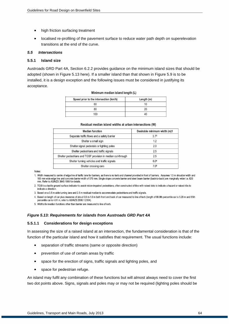
Guidelines for Road Design on Brownfield Sites
Guidelines, Transport and Main Roads, July 2013 64
high friction surfacing treatment
localised re-profiling of the pavement surface to reduce water path depth on superelevation
transitions at the end of the curve.
5.5 Intersections
5.5.1 Island size
Austroads GRD Part 4A, Section 6.2.2 provides guidance on the minimum island sizes that should be
adopted (shown in Figure 5.13 here). If a smaller island than that shown in Figure 5.9 is to be
installed, it is a design exception and the following issues must be considered in justifying its
acceptance.
Figure 5.13: Requirements for islands from Austroads GRD Part 4A
5.5.1.1 Considerations for design exceptions
In assessing the size of a raised island at an intersection, the fundamental consideration is that of the
function of the particular island and how it satisfies that requirement. The usual functions include:
separation of traffic streams (same or opposite direction)
prevention of use of certain areas by traffic
space for the erection of signs, traffic signals and lighting poles, and
space for pedestrian refuge.
An island may fulfil any combination of these functions but will almost always need to cover the first
two dot points above. Signs, signals and poles may or may not be required (lighting poles should be

Guidelines for Road Design on Brownfield Sites
Guidelines, Transport and Main Roads, July 2013 65
avoided as there will usually be an alternative location that can provide a suitable solution).
Pedestrians are not always present and sometimes only in small numbers.
If the space available for the island is too small, it will become more of a hazard in itself and a painted
island will suffice.
Where signs are required in the island, there must be sufficient space to accommodate the full width of
the sign plus clearance to the edges of the sign as defined in the MUTCD. In rural areas, the minimum
clearance to the edge of the sign is 600 mm from the road edge; in urban areas, the minimum is
300 mm from the face of the kerb but 500 mm from the face of a mountable or semi-mountable kerb.
Hence the width of the island required will be the width of the sign plus the required clearance on both
sides.
The length of the island may need to be shorter than the dimensions provided in Austroads GRD Part
4A (Table 6.2). A sensible minimum, given severe site constraints could be taken as 2 x the width
determined from the functional requirements with a minimum of 3.0 m. Such an island would be very
small in area and would need significant treatment to ensure sufficient conspicuity.
5.5.1.2 Mitigation
The major issue with a small island will be its conspicuity. Additional measures to make the island
conspicuous will be required. This could include:
painting the island and kerbs in chevron style with high reflectivity paint
using wider lead-in lane lines and raised pavement markers, and
lighting will be essential.
5.5.2 Turning lanes
Width of turn lanes at intersections is predicated on the turning path of the design vehicle and
clearances to adjacent kerbs. It is usual to provide sufficient width to pass a stopped vehicle
(combination of lane and shoulder width) and this is addressed in Austroads GRD Part 4A. The
minimum width is set at 5.0 m but is not mandatory, the ability to pass a stopped vehicle being allowed
to be achieved by using space beyond the kerb line (surface of islands). In such cases, the kerbs must
be mountable or semi-mountable and furniture (signals, signs) must be kept clear of the area
potentially used by passing vehicles.
The width of a right turn lane in the median of an intersection is desirably 3.5 m but widths of 3.0 m
have often been used. The minimum width that could be tolerated is 2.5 m which will accommodate a
passenger car. This should only be used if the adjacent lane is 3.5 m wide. This would be a design
exception.
Mitigation includes:
Ensuring the adjacent travel lane is at least 3.5 m;
Ensuring that the adjacent median can tolerate incursion by the wheels of a vehicle i.e.
sufficient clearance to any road furniture and sufficient space for a pedestrian to be shielded.
Preferably, the operation of the intersection should be such that pedestrians do not need to be
stored on the median during the crossing manoeuvre.
If the pavement or surfacing is being replaced through an intersection, consider re-marking any AUR
(Auxiliary Right Turn Treatment) or older Type B turn treatment as a CHR(S) layout. Whilst this is

Guidelines for Road Design on Brownfield Sites
Guidelines, Transport and Main Roads, July 2013 66
subject to the turn treatment meeting all of the design criteria for CHR(S) layouts in Chapter 13 of the
RPDM 1st Edition, EDD allows a CHR(S) that fits within the 'footprint' of an AUR.
5.5.3 Private accesses
Private property access on rural roads can become hazardous with reasonably high traffic volumes
combined with high speed. Drivers waiting to turn right from the major road are susceptible to rear end
collisions. In many cases, it is not feasible to provide separate service roads or to provide a protected
right turn lane for such accesses.
One potential solution is to provide a widened shoulder (3.0 m with 1 in 25 tapers from the usual
shoulder edge) opposite the access to allow the turning vehicle to wait until traffic is clear in both
directions and then undertake the right hand turn (sometimes referred to as a “hook” turn) - Figure
5.14. This solution must be developed in consultation with the property owners. It is important that the
size of the widening does not convey a message that it is an overtaking lane.
Left hand turns should be provided with shoulder widening to allow the vehicle turning left to move
clear of the through lane edge. 1 in 10 tapers to achieve a 3 m shoulder adjacent to the access is
required.
Property accesses must be removed from either side of the crest of sub-standard vertical curves i.e.
just over the crest in either direction (refer to Section 5.3). In some cases, an access precisely on the
crest with equal visibility in both directions will be acceptable – appropriate earthworks to provide
suitable visibility of the access will be required. Allowing accesses without at least EDD sight distance
is not acceptable as there is little in the way of mitigation that can be done. Even if the primary user is
familiar with the environment, that user will not be able to detect an oncoming vehicle and to the
oncoming vehicle, an entering or exiting vehicle will be a complete surprise with little scope for taking
avoiding action.

Guidelines for Road Design on Brownfield Sites
Guidelines, Transport and Main Roads, July 2013 67
Figure 5.14: Example Private Entrance Widening - Hook Right Turns
5.6 Temporary works
Temporary works required for construction must always be designed appropriately in accordance with
the same principles used for all roads. In general, temporary roads should be designed to appropriate
EDD standards but in many cases, constraints on the design because of, for example, limitations of
space, environmental impacts and effects on surrounding development, will make this too expensive
to achieve. In addition, the temporary road may be of a higher standard than the existing road on
which the construction is occurring.
It is therefore acceptable to adopt EDD and Design Exceptions principles in the design of temporary
works where such restrictions apply. Appropriate mitigation strategies will still be required to ensure a
safe outcome for the project.
6 Conclusions
6.1 General
It is often the case that brownfield sites have geometric features that do not accord with current design
manual requirements and that the cost of improvement to the current standard is excessive.
Attempting to provide the current standard will use resources that could be better spent on other
issues on the road network, provided that the case under consideration will still operate to an
acceptable level of safety.
Each situation will be unique since the conditions at each site will be different – traffic volumes,
topography, crash rate, types of crashes, materials and cost of construction will vary. It is therefore not
practicable to develop “standard” values for design exceptions for all circumstances. Nor would it be

Guidelines for Road Design on Brownfield Sites
Guidelines, Transport and Main Roads, July 2013 68
wise to do so since it is necessary to justify the decision to adopt a design exception and fully
document the reasons for it and the methods used to mitigate any adverse consequences.
Sufficient information will be required to demonstrate that the adopted solution (including the mitigation
strategies) will not make the safety situation any worse and that preferably, the safety of the site is
improved. Application of appropriate tools such as the ARRB Road Safety Risk Manager and the
RISC software (Qld) should be used to demonstrate the substantive safety of the proposed solution.
Every case will require a risk analysis that will include consideration of the crash history of the site,
adjacent sections of road and perhaps of other roads of this type in the State. Value engineering will
need to be applied to ensure that the optimum solution is adopted.
This implies that a range of options will be considered, at least including the “retain existing” case and
the upgrade to NDD standard case. Other options may include improving the standard to the EDD for
the values where the exceptions have been used.
It is desirable that the standards to which a section of road is to be designed when works take place
have been identified at the earliest part of the pre-construction process possible. If possible, they
should be decided, with appropriate justification and documentation when the Link Studies are
undertaken, the specific incremental improvement works being identified and the appropriate
standards defined.
6.2 Procedures
The procedures to be undertaken to obtain approval of the required standards are well defined in the
RPDM 2nd
Edition. These apply to the adoption of both EDD and Design Exception values. The
documentation required is also well defined and it is essential that this documentation is
comprehensive to provide adequate information for the defence of the design decisions when the
need arises, sometimes many years after the implementation of the project.
It is clear that each design exception requires appropriate engineering analysis and judgement. The
principles of engineering analysis need to be applied to solve the problem at hand with a solution that
is robust and defendable. Standard “off-the-shelf” solutions will rarely be able to be adopted without
modification and all will require justification as discussed in various sections of these guidelines.
It is also clear that to be defendable the system needs to have a review process where the designs
implemented are monitored over an extended period of time to provide strong evidence of
performance. The results of this monitoring can then be used to make changes to the process where
required and/or to provide additional justification for the values adopted. Effective monitoring will
ensure that the bona fides of the system are demonstrated.
While some guidance has been provided on possible values for some parameters as design
exceptions, each case will have to be analysed on its merits and appropriate engineering judgement
applied to find the optimum solution.
6.3 Recommendations
In the first instance, designers should check the RPDM 2nd Edition to establish what criteria have
been established for the parameters involved. In many cases, the issue has already been addressed
and acceptable approaches to the problem established.
Where possible, these guidelines includes quantitative values for parameters that may not meet NDD
standards on the existing road. It is recommended that these be used as guides to a suitable starting

Guidelines for Road Design on Brownfield Sites
Guidelines, Transport and Main Roads, July 2013 69
point for analysis and development of an appropriate solution. Every case must be evaluated on its
merits according to the particular circumstances at the site in question and documented thoroughly as
described in earlier sections of the report. The EDD and Design Exceptions Summary Report form
provides a good framework for such a report (refer to Appendix A).
It is essential that the approach to retention of design exceptions is decided on robust engineering
principles, using good engineering judgement and applying strong engineering analysis. Standard
solutions will rarely be satisfactory and should only be used as starting points for the development of
the solution to the problem.
Where there are unique design exceptions proposed design exceptions with values will outside the
design domain, a system of monitoring sites where design exceptions have been retained to
determine the success of the measures used and to provide information to improve the guidelines
used by designers.
7 References
AASHTO (2009): Manual for Assessing Safety Hardware (MASH). American Association of
State Highway and Transportation Officials 2009
AASHTO (2010) Highway Safety Manual Edition 1, American Association of Highway and
Transportation Officials, Washington DC
Alberta Transportation (2010): Design Standards/Practice Exception Request Process. Design
Bulletin #72/2010.
http://www.transportation.alberta.ca/Content/docType233/Production/Design%20Bulletin72%2
02010%20August%202010.pdf, Accessed October 2012
Arndt O K, R L. Cox, S C Lennie and M T Whitehead (2011): Provision of Sight Distance
around Concrete Barriers and Structures on Freeways and Interchanges. Paper prepared for
the 90th Annual Transportation Research Board Annual Meeting
ARRB (2012): SP1705 Progress Report No.5: Safe System Design Principles for Brownfield
Sites
Austroads (2009): Road Safety Engineering Risk Assessment Stage 6: Overview of Research
(Internal Report IR-168/09)
Austroads (2010a): Road Safety Engineering Risk Assessment Part 1: Relationship between
Crash Risk and the Standards of Geometric Design Elements (Report AP-T146/10)
Austroads (2010b): Road Safety Engineering Risk Assessment Part 6: Crash Reduction
Factors (Report AP-T151/10)
Austroads (2010c): Guide to road design Part 6: Roadside Design, Safety and Barriers,
Publication number Publication No. AGRD06/10, Austroads, Sydney Australia
Austroads Guide to Road Design
Austroads Guide to Road Safety
Austroads Guide to Traffic Management

Guidelines for Road Design on Brownfield Sites
Guidelines, Transport and Main Roads, July 2013 70
Baran, Michelle (2008): Road Safety – A New Set of PIARC Guidelines (accessed on the
PIARC web site (www. piarc.org) on 13 May 2012)
Burbridge, Andrew and R. J. Troutbeck (2012): Evaluating the Risk Associated with Reduced
Deflection Distances behind Road Safety Barriers at Brownfield Sites – prepared for
Department of Transport and Main Roads
Caltrans (2010): Exceptions to Design Standards
Cox, Ricky L (2003): Reduced sight distance on existing rural roads. How can we defend it?
(21st ARRB and 11
th REAAA Conference, Cairns Qld 2003)
Cox, Ricky L. (2004): Extended Design Domain and Potential Liability (with acknowledgement
to Anne-Marie Foley and Michael Mailloux - DTMR Strategic Legal and Legislation)
Cox, Ricky L, Sandra Lennie and Dr. Owen Arndt (2012): A revised Technical Foundation for
Cross Section for Rural Roads in Queensland (25th ARRB Conference Perth WA 2012)
Fambro, D, K. Fitzpatrick, & R. Koppa, R (1997): Determination of stopping sight distances,
NCHRP report 400, Transportation Research Board, Washington, DC
Federal Highway Administration (USA) Resource Centre (2008): Developing Strong
Justifications for Design Exceptions
Federal Highway Administration (USA) (2009): Safety Evaluation of Improved Curve
Delineation (Techbrief FHWA-HRT-09-046)
Fitzpatrick, K., Fambro, D., & Stoddard, A. (2000). Safety effects of limited stopping sight
distance on crest vertical curves. Transportation Research Record, 1701, 17-24
Florida Department of Transportation (2008): Innovative Operational Safety Improvements at
Unsignalised Intersections Final Report
Glennon, J (1987b): Effect of alignment on highway safety, in Relationship between safety and
key highway features: a synthesis of prior practice, state of the art report 6, Transportation
Research Board, Washington, DC, pp. 48-63
Gross, F, B Persaud and C Lyon (2010): A Guide to Developing Quality Crash Modification
Factors, Federal Highway Administration Report FHWA-SA-10-032
Guyano-Cardona, Jocelyn; Peter Sylvester; and Ian Jenkins (2002): Four-Way Stop Signs:
The Newcastle Experience. Australian Institute of Traffic Planning and Management (AITPM)
National Conference , 2002, Perth, Western Australia, p. 139-49
Heimbach, C, Cribbins, P & Chang, M. (1983): Some partial consequences of reduced traffic
lane widths on urban arterials, Transportation Research Record, no. 923, pp. 69-72
Hildebrand, Eric D., Frank R. Wilson and James J. Copeland (2005): Supplemental Speed
Reduction Treatments for Rural Work Zones (in Hennessey, Dwight A and David L.
Wiesenthal (2005): Contemporary Issues in Road User Behaviour and Traffic Safety (Nova
Science Publishers, New York))
Levett, S. (2005): The application of asymmetrical design principles to rural roads,
Australasian Road Safety Research, Policing, Education Conference, 2005, Wellington, New
Zealand, Ministry of Transport, Wellington, New Zealand, 9 pp

Guidelines for Road Design on Brownfield Sites
Guidelines, Transport and Main Roads, July 2013 71
Levett, Stephen (2007): Retro-fitting Road Safety to Existing Rural Roads – RTA, NSW
Mathews, LR & Barnes, JW (1988), ‘Relation between road environment and curve accidents’,
Australian Road Research Board Conference, 14th, 1988, Canberra, ARRB, Vermont South,
Vic., vol. 14, no. 4, pp. 105-20
Maunsell McIntyre Pty Ltd (2001): Non-Standard Intersection Control Discussion Paper –
prepared for Qld Dept of Main Roads
Minnesota Dept of Transportation (2010): Design Standards and Exceptions.
http://dotapp7.dot.state.mn.us/edms/download?docId=623068, Accessed October 2012
Mullin, E (1972): The changing approach to road design, Main Roads, vol. 35, no. 1, pp. 9-14
National Cooperative Highway Research Program (NCHRP) (2003): Report 500: Guidance for
Implementation of the AASHTO Strategic Highway Safety Plan (13 volumes)
NCHRP (2012): Recent Roadway Geometric Design Research for Improved Safety and
Operations – A Synthesis of Highway Practice. NCHRP Synthesis 432
National Transport Commission (2007): Performance Based Standards Scheme – Network
Classification Guidelines. http://www.ntc.gov.au/viewpage.aspx?documentid=1283. Accessed
October 2012
New Jersey Department of Transportation (USA) (2012): Design Exception Manual
NYS DOT (2003): Roadside design, guide rail, and appurtenances, in Highway design
manual, chapter 10, revision 41, New York State Department of Transportation, Albany, NY,
USA
Olson, PL, Cleveland, DE, Fancher, PS, Kostyniuk, LP & Schneider, LW, (1984): Parameters
affecting stopping sight distance, NCHRP report 270, Transportation Research Board,
Washington, DC
Oxley, Jennifer; Bruce Corben, Sjaanie Koppel, Brian Fildes, Nisha Jacques, Mark Symmons
and Ian Johnston (2004): Cost-Effective Infrastructure Measures on Rural Roads - Monash
University Accident Research Centre – Report No. 217
Parker, Terri L. (2012): Tort Liability Defence Practices for Design Flexibility – NCHRP Legal
Research Digest 57
PIARC (1991): Safety Improvements on Inter-urban Roads. Report No. 3825, 04-01-B
Queensland Department of Main Roads (2009): Report on Proposal to Upgrade Sections of
Murphy’s Creek Road
Queensland DTMR (2002): Traffic and Road Use Management Manual, Volume 3 Road
Safety – Rumble Strips
Queensland DTMR (2003): Manual of Uniform Traffic Control Devices (MUTCD) [last issued
2011]
Queensland DTMR (2010a): Guidelines for Strengthening and Widening – Nation Building
Program (2009/10 – 2013/14)
Queensland DTMR (2010b): Guidelines for overtaking Lanes - Nation Building Program
(2009/10 – 2013/14)
Guidelines for Road Design on Brownfield Sites
Guidelines, Transport and Main Roads, July 2013 72
Queensland DTMR (2010c): Guidelines for the Rest Area Program (Bruce and Warrego
Highways) - Nation Building Program (2009/10 – 2013/14)
Queensland DTMR (2011): Road Planning and Design Manual 1st Edition
Queensland DTMR (2011): Road Planning and Design Manual 2nd Edition
Queensland DTMR (2012): A Guideline for the inclusion of Cycling Facilities into Pavement
Rehabilitation and Road Resurfacing Projects (draft prepared by Opus Consultants)
Queensland DTMR (2011): Design Guidelines – Transport Network Reconstruction Program
(TNRP)
Queensland DTMR (2009): Preconstruction Processes Manual
Ross, H E Jnr., D L Sicking, R A Zimmer and J D Michie (1993): Recommended Procedures
for the Safety Performance Evaluation of Highway Features. National Cooperative Highway
Research program Report 350, Transportation Research Board
RTA (NSW) (2007): Brownfields Road Design Guide
SKM (2011): Sydney Road Bicycle Lane Monitoring (Draft report for VicRoads)
Stein W J and T R Neuman (2007): Mitigation Strategies for Design Exceptions, Federal
Highway Administration Report FHWA-SA-07-011
Transportation Research Board (1987), Designing safer roads: practices for resurfacing,
restoration and rehabilitation, special report 214, TRB, Washington, DC
Troutbeck, R J (2012a): The installation of safety barriers on, or near, embankments on
existing roads – prepared for Qld Department of Transport and Main Roads
Troutbeck, R J (2012b): The installation of wire rope barriers in narrow medians – prepared for
Qld Department of Transport and Main Roads
Troutbeck, R J (2012c): The installation of safety barriers on embankments – prepared for Qld
Department of Transport and Main Roads
Troutbeck, R J (2012d): The performance of concrete barriers less than 1100 mm high –
prepared for Qld Department of Transport and Main Roads
Troutbeck, R J (2012e): Notes on the crash Modification Factors for Wide Centreline
Treatments (WCLT) – prepared for Qld Department of Transport and Main Roads
Troutbeck, R J (2012f): Vehicle impacts into barriers with kerbs installed nearby - prepared for
Qld Department of Transport and Main Roads October 2012
Troutbeck, R J (2012g): Proposed cross sections for the Bruce Highway Upgrade - prepared
for Qld Department of Transport and Main Roads August 1012
Troutbeck, R J (2012h): The effectiveness of rounding the verge hinge point on vehicles'
trajectories - prepared for Qld Department of Transport and Main Roads October 2012
Troutbeck, R J (2012i): Considerations for clear zones on rural roads - prepared for Qld
Department of Transport and Main Roads June 2012

Guidelines for Road Design on Brownfield Sites
Guidelines, Transport and Main Roads, July 2013 73
Troutbeck, R J (2012j): The installation of safety barriers on embankments batter slopes
steeper than 1 on 10 - prepared for Qld Department of Transport and Main Roads August
2012
Vicroads (2010): Supplement to the Austroads Guide to Road Design Part 2 Design
Considerations
Whittaker, Adam (2012): The Safety Benefits of Continuous Narrow Painted Median Strips
(DTMR Engineering Technology Forum 2012)

Guideline for Road Design on Brownfield Sites: Appendix B
Guideline, Transport and Main Roads, July 2013 74
Appendix A: Example EDD and Design Exception Summary Report

Guideline for Road Design on Brownfield Sites: Appendix B
Guideline, Transport and Main Roads, July 2013 75

Guideline for Road Design on Brownfield Sites: Appendix B
Guideline, Transport and Main Roads, July 2013 76

Guideline for Road Design on Brownfield Sites: Appendix B
Guideline, Transport and Main Roads, July 2013 77

Guideline for Road Design on Brownfield Sites: Appendix B
Guideline, Transport and Main Roads, July 2013 78
Appendix B: Mitigation Strategies
The following table is reproduced from “Mitigation Strategies for Design Exceptions” Stein and
Neuman (2007) [FHWA] – Table 2.2.
Design Element Objective Potential Mitigation Strategies
1. Design Speed Reduce operating speeds to the design speed.
Cross-sectional elements to manage speed. Speed limit reduction if drive expectations meet.
2. Lane Width
&
3. Shoulder
Width
Optimize safety and operations by distributing available cross-sectional width.
Select optimal combination of lane and shoulder width based on site characteristics.
Provide advance warning of lane width reduction.
Signing
Improved ability to stay within the lane
Wide pavement markings
Recessed pavement markings
Raised pavement markings
Delineators
Lighting
Centreline rumble strips
Shoulder rumble strips
Painted edge line rumble strips
Improve ability to recover if driver leaves the lane
Paved or partially-paved shoulders
Safety edge
Reduce crash Severity if driver leaves the roadway
Remove or relocate fixed objects
Traversable slopes.
Breakaway safety hardware
Shield fixed objects and steep slopes
Provide space for enforcement and disable vehicles
Lay-by areas
4. Bridge Width
Provide advanced warning and delineation of narrow bridge
Improve visibility of narrow bridge, bridge rail, and lane lines
Signing
Reflectors on approach guardrail and bridge rail
Post-mounted delineators
Object markers
High-visibility bridge rail
Bridge lighting
Enhanced pavement markings
Maintain pavement on bridge that will provide safety driving conditions
Skid-resistant pavement
Anti-icing systems
Reduce crash severity if driver leaves the roadway
Crashworthy bridge rail and approach guardrail
Provide space for disable vehicles or emergencies on long bridges.
Lay-by areas

Guideline for Road Design on Brownfield Sites: Appendix B
Guideline, Transport and Main Roads, July 2013 79
Design Element Objective Potential Mitigation Strategies
5. Horizontal
Alignment
&
6.Superelevation
Provide quick response to disable vehicles or emergencies on long bridges. Provide advanced warning.
Surveillance.
Signing
Pavement marking messages
Dynamic curve warning systems
Provide delineation
Chevrons
Post-mounted delineators
Reflectors on barrier
Improve ability to stay within the lane
Improve ability to recover if driver leaves the lane
Widen the roadway
Skid-resistant pavement
Enhanced pavement markings
Lighting
Centreline rumble strips
Shoulder rumble strips
Painted edge line rumble strips
Paved or partially paved shoulders
Safety edge
Reduce crash severity if driver leaves the roadway
Remove or relocate fixed objects
Traversable slopes
Breakaway safety hardware
Shield fixed objects and steep slopes
7.Vertical
Alignment See (8) Grade and (9) Stopping Sight Distance.
8. Grade
Provide advance warning Signing
Improve safety and operations for vehicles ascending or descending steep grades
Climbing lanes
Downgrade lanes
Capture out-of-control vehicles descending steep grades
Escape ramps
Improve ability to stay within the lane
Enhanced pavement markings
Delineators
Centreline rumble strips
Shoulder rumble strips
Painted edge line rumble strips
Improve ability to recover if driver leaves the lane
Reduce crash severity if driver leaves the roadway
Paved or partially paved shoulders
Safety edge
Remove or relocate fixed objects
Traversable slopes
Breakaway safety hardware
Shield fixed objects and steep slopes

Guideline for Road Design on Brownfield Sites: Appendix B
Guideline, Transport and Main Roads, July 2013 80
Design Element Objective Potential Mitigation Strategies
Address drainage on flat grades
Adjusting gutter profile on curbed cross sections
Continuous drains
9. Stopping
Sight Distance
Mitigate site distance restrictions
Signing and speed advisory plaques (crest vertical curves
Lighting (sag vertical curves)
Adjust placement of lane within the roadway cross section (horizontal)
Improve ability to avoid crashes
Cross-sectional elements to manage speed
Wide shoulders
Wider clear recovery area
Improve driver awareness on approach to intersections
Advance warning signs
Dynamic warning signs.
Larger or additional STOP/YIELD signs
Intersection lighting
10. Cross Slope
Provide warning of slick pavement Signing
Improve surface friction
Improve drainage
Pavement grooving (PCC pavement)
Open-graded friction courses (HMA pavement)
Transverse pavement grooving (PCC pavement)
Open-graded friction courses (HMA pavement)
Pavement edge drains
Mitigate cross-slope break on the high side of superelevated curves
Modified shoulder cross slope
11. Vertical
Clearance
Advance warning
Preventing impacts with low structures
Signing
Alternate routes
Large vehicles restrictions
12. Lateral
Offset to
Obstruction
Improve visibility of objectives near the roadway
Delineate objects
Lighting
Optimize operations by distributing available cross-sectional width
Provide full outside lane width and/or additional offset
Improve visibility of the lane lines Enhanced pavement markings
13.Structural
Capacity Not addressed in this Guide

Guideline for Road Design on Brownfield Sites: Appendix C
Guideline, Transport and Main Roads, July 2013 81
Appendix C: Application of Crash Modification Factors
Crash Modification Factors (CMF’s) are used to establish the change in crash frequency when a
road’s attribute is changed from a benchmark configuration. Typically, a CMF is defined as follows:
A CMF is a multiplicative factor used to compute the expected number of crashes after implementing a
given countermeasure at a specific site. The CMF is multiplied by the expected crash frequency
without treatment. A CMF greater than 1.0 indicates an expected increase in crashes, while a value
less than 1.0 indicates an expected reduction in crashes after implementation of a given
countermeasure. For example, a CMF of 0.8 indicates an expected safety benefit; specifically, a 20
percent expected reduction in crashes. A CMF of 1.2 indicates an expected degradation in safety;
specifically, a 20 percent expected increase in crashes.
The AASHTO (2010) Highway Safety Manual Edition 1 has guidance on the application of CMF’s. The
application of CMF’s relate to crash type (e.g.: run off road, head-on etc) and the specific mitigation
treatment applied to combat that crash type event. The following is one method that can be
considered to determine the resultant number of crashes at a site.
Step 1 - Previous/Current Situation
(A) Identify “number of” & “description/type of” crashes along road project length.
(B) Identify previous traffic volume per km over previous project accident life
( e.g.: AADT x 365days x number of years relevant to crash history record)
Baseline CMF Formula = 1.00 (ie: Number of crashes in history period per traffic volume per
km)
Step 2 - Projected/Predicted Situation using CMF for particular treatment
(A) Identify predicted traffic volume ie: AADT x (traffic growth %) x Design Life (yrs)
(B) Identify number of predicted crashes in future Design life without mitigation treatments
Crash Rate (from Step 1) x Step 2(A)= Number of crashes/traffic volume/km
Resultant Number of Crashes = CMF x Step2(B) (Crash Number per Vehicle volume/km)

Guideline for Road Design on Brownfield Sites: Appendix C
Guideline, Transport and Main Roads, July 2013 82
Figure C1: Crash Modification Factors for Traffic Lane Width (Stein and Neuman 2007)
Figure C2: Crash Modification Factors for Shoulder Width on two lane rural highways
(NCHRP Report 500 Vol 6)

Guideline for Road Design on Brownfield Sites: Appendix D
Guideline, Transport and Main Roads, July 2013 83
Appendix D: DTMR Guideline on Shoulder Widths to Support Cycling
DTMR Guideline on shoulder width requirements to support cycling on sealed roads in rural areas with
an 80+ km/h posted speed limit
Priority cycle
route? AADT (vehicles per day) Provision for cyclists
Yes
>12,000 2.0m minimum sealed shoulder (3.5m lanes) but 2.5m sealed shoulder preferred
6000 – 12,000 2m minimum sealed shoulder (3.5m lanes)
<6000 1.5m minimum sealed shoulder
No
>3000 Minimum 10m formation (1.5m minimum sealed shoulder + 3.5m lane width)
1000 – 3000 Minimum 9.0m formation (1.0m sealed shoulder + 3.5m lane or 1.5m sealed shoulder + 3.0m lane)
300-1000 Minimum 8.0m formation (0.5m sealed shoulder + 3.5m lane or 1.0m sealed shoulder + 3.0m lane)
<300 No special provision
Notes:
A priority cycle route can be either one identified in a Principal Cycle Network Plan, or in a local government cycle network plan that has been endorsed by Main Roads.
These widths are for where there is no roadside barrier. Where there is a roadside barrier, the shoulder widths shown. For new projects or upgrading works, the decision criteria should be based on design traffic, not current traffic. Typically, design traffic is calculated on a post-construction design life of 20 years for rural roads.
These widths may need to be increased for other factors such as a high percentage of heavy vehicles, strong wind effects, steeper grades, and high numbers of cyclists.
Ensure seal covers full width of pavement (including during rehabilitation).
Within a 20 km radius of towns a 10 mm maximum seal size is recommended.
Within a 20 km radius of towns, seal size on the shoulder should provide a riding surface smooth enough for bicycles with narrow racing tyres (ideally a 10 mm seal size or other combination to achieve equivalent smoothness).

Guideline for Road Design on Brownfield Sites: Appendix E
Guideline, Transport and Main Roads, July 2013 84
Appendix E: Wide Central Line Marking Safety Treatments

Guideline for Road Design on Brownfield Sites: Appendix E
Guideline, Transport and Main Roads, July 2013 85

Guideline for Road Design on Brownfield Sites: Appendix E
Guideline, Transport and Main Roads, July 2013 86

Guideline for Road Design on Brownfield Sites: Appendix E
Guideline, Transport and Main Roads, July 2013 87

Guideline for Road Design on Brownfield Sites: Appendix E
Guideline, Transport and Main Roads, July 2013 88

Guideline for Road Design on Brownfield Sites: Appendix E
Guideline, Transport and Main Roads, July 2013 89

Guideline for Road Design on Brownfield Sites: Appendix E
Guideline, Transport and Main Roads, July 2013 90

Guideline for Road Design on Brownfield Sites: Appendix E
Guideline, Transport and Main Roads, July 2013 91

Guideline for Road Design on Brownfield Sites: Appendix E
Guideline, Transport and Main Roads, July 2013 92

Guideline for Road Design on Brownfield Sites: Appendix E
Guideline, Transport and Main Roads, July 2013 93

Guideline for Road Design on Brownfield Sites: Appendix E
Guideline, Transport and Main Roads, July 2013 94

Guideline for Road Design on Brownfield Sites: Appendix F
Guideline, Transport and Main Roads, July 2013 95
Appendix F: Shoulder Widening on Horizontal Curves
The following is an extract from Levett (2007): Retro-fitting Road safety to Existing Rural Roads.

Guideline for Road Design on Brownfield Sites: Appendix F
Guideline, Transport and Main Roads, July 2013 96

Guideline for Road Design on Brownfield Sites: Appendix F
Guideline, Transport and Main Roads, July 2013 97

Guideline for Road Design on Brownfield Sites: Appendix F
Guideline, Transport and Main Roads, July 2013 98

Guideline for Road Design on Brownfield Sites: Appendix F
Guideline, Transport and Main Roads, July 2013 99

Guideline for Road Design on Brownfield Sites: Appendix G
Guideline, Transport and Main Roads, July 2013 100
Appendix G: EDD and Design Exception Report Applications
NOT YET INCLUDED.
