guidelines for heat recovery - eurovent.eu rec 17...guidelines for heat recovery . eurovent 17/11 -...
TRANSCRIPT
Eurovent 17/11 - 2015
Guidelines for Heat Recovery

Eurovent 17/11 - 2015
First Edition
Published by EUROVENT
Bd. Auguste Reyers Ln 80
1030 Brussels, Belgium
Tel: 00 33 (0)1 7544 7171
E-mail: [email protected]

Eurovent 17/11 - 2015
Page 3 of 13
Foreword
This document is provided by the EUROVENT Association and was prepared by the product
group PG-ERC (Energy Recovery Components). EUROVENT Association does not grant any
certification based on this document. Certification is granted by Eurovent Certita Certification,
which is a legal entity different from EUROVENT Association.
1. Introduction
Eurovent Certita Certification rated performance for air-to-air heat exchangers is established
with balanced mass flow conditions on the supply and return air side. From a measurement
point of view this is achieved at low duct pressure differences around the heat exchangers,
which is defined in EN 308 and the Eurovent Certita Certification Operational Manual and
Rating Standards. This allows the comparison of technical performance as efficiency and
pressure drop between different manufacturers’ products. Nevertheless in real air handling
systems optimum conditions are seldom met, and depending on the duct pressure differences
air leakage needs to be considered during the system design phase.
2. Leakage
2.1. Definitions
Air leakage is defined in prEN 16798-3:2014 by two ratios:
Outdoor air correction factor (OACF) [ ]
Exhaust air transfer ratio (EATR) [%]
Outdoor Air Correction Factor (OACF) [-]: Ratio of Supply Air Inlet
(21) mass flow divided by the Supply Air Outlet (22) mass flow.
𝑂𝐴𝐶𝐹 =𝑞𝑚,21
𝑞𝑚,22
With OACF > 1 more air is transferred from the supply to the
exhaust air side and with OACF < 1 more air is transferred from exhaust to supply air side
(recirculation of exhaust air). In general OACF is a measure expressing the difference between
outdoor and supply mass airflow and is used to correct the Supply Air Inlet mass flow in order
to meet the required Supply Air Outlet mass flow to the building (see 2.3.2).
Exhaust Air Transfer Ratio (EATR) [%]: percentage of the exhaust air inlet going back to the
supply air outlet. With 𝑞𝑚,22,𝑛𝑒𝑡 the portion of the Supply Air Outlet mass flow that originated as
Supply Air Inlet (Net Supply Air Outlet Mass Flow), EATR is defined as:
𝐸𝐴𝑇𝑅 =𝑞𝑚,22 − 𝑞𝑚,22,𝑛𝑒𝑡
𝑞𝑚,22= 1 −
𝑞𝑚,22,𝑛𝑒𝑡
𝑞𝑚,22
EATR is measured by gas concentrations of inert gas and represents the exhaust air leakage
to the supply airflow, which is in general described as internal exhaust air leakage.
Internal exhaust air leakage can occur by two different mechanisms:
12 11
21 22
Eurovent 17/11 - 2015
Page 4 of 13
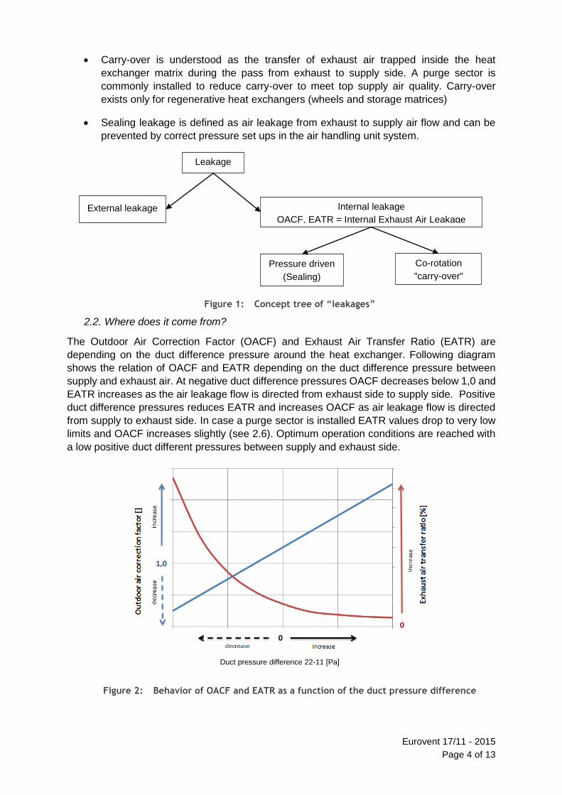
Carry-over is understood as the transfer of exhaust air trapped inside the heat
exchanger matrix during the pass from exhaust to supply side. A purge sector is
commonly installed to reduce carry-over to meet top supply air quality. Carry-over
exists only for regenerative heat exchangers (wheels and storage matrices)
Sealing leakage is defined as air leakage from exhaust to supply air flow and can be
prevented by correct pressure set ups in the air handling unit system.
Figure 1: Concept tree of “leakages”
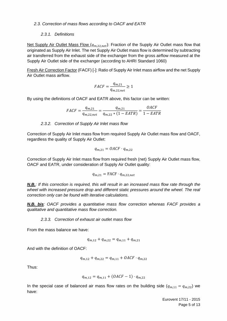
2.2. Where does it come from?
The Outdoor Air Correction Factor (OACF) and Exhaust Air Transfer Ratio (EATR) are
depending on the duct difference pressure around the heat exchanger. Following diagram
shows the relation of OACF and EATR depending on the duct difference pressure between
supply and exhaust air. At negative duct difference pressures OACF decreases below 1,0 and
EATR increases as the air leakage flow is directed from exhaust side to supply side. Positive
duct difference pressures reduces EATR and increases OACF as air leakage flow is directed
from supply to exhaust side. In case a purge sector is installed EATR values drop to very low
limits and OACF increases slightly (see 2.6). Optimum operation conditions are reached with
a low positive duct different pressures between supply and exhaust side.
Figure 2: Behavior of OACF and EATR as a function of the duct pressure difference
Leakage
External leakage Internal leakage
OACF, EATR = Internal Exhaust Air Leakage
Pressure driven
(Sealing)
Co-rotation
"carry-over"
Duct pressure difference 22-11 [Pa]
Eurovent 17/11 - 2015
Page 5 of 13
2.3. Correction of mass flows according to OACF and EATR
2.3.1. Definitions
Net Supply Air Outlet Mass Flow (𝑞𝑚,22,𝑛𝑒𝑡): Fraction of the Supply Air Outlet mass flow that
originated as Supply Air Inlet. The net Supply Air Outlet mass flow is determined by subtracting
air transferred from the exhaust side of the exchanger from the gross airflow measured at the
Supply Air Outlet side of the exchanger (according to AHRI Standard 1060)
Fresh Air Correction Factor (FACF) [-]: Ratio of Supply Air Inlet mass airflow and the net Supply
Air Outlet mass airflow.
𝐹𝐴𝐶𝐹 =𝑞𝑚,21
𝑞𝑚,22,𝑛𝑒𝑡≥ 1
By using the definitions of OACF and EATR above, this factor can be written:
𝐹𝐴𝐶𝐹 =𝑞𝑚,21
𝑞𝑚,22,𝑛𝑒𝑡=
𝑞𝑚,21
𝑞𝑚,22 ∗ (1 − 𝐸𝐴𝑇𝑅)=
𝑂𝐴𝐶𝐹
1 − 𝐸𝐴𝑇𝑅
2.3.2. Correction of Supply Air Inlet mass flow
Correction of Supply Air Inlet mass flow from required Supply Air Outlet mass flow and OACF,
regardless the quality of Supply Air Outlet:
𝑞𝑚,21 = 𝑂𝐴𝐶𝐹 ⋅ 𝑞𝑚,22
Correction of Supply Air Inlet mass flow from required fresh (net) Supply Air Outlet mass flow,
OACF and EATR, under consideration of Supply Air Outlet quality:
𝑞𝑚,21 = FACF ⋅ 𝑞𝑚,22,𝑛𝑒𝑡
N.B.: If this correction is required, this will result in an increased mass flow rate through the
wheel with increased pressure drop and different static pressures around the wheel. The real
correction only can be found with iterative calculations.
N.B. bis: OACF provides a quantitative mass flow correction whereas FACF provides a
qualitative and quantitative mass flow correction.
2.3.3. Correction of exhaust air outlet mass flow
From the mass balance we have:
𝑞𝑚,12 + 𝑞𝑚,22 = 𝑞𝑚,11 + 𝑞𝑚,21
And with the definition of OACF:
𝑞𝑚,12 + 𝑞𝑚,22 = 𝑞𝑚,11 + 𝑂𝐴𝐶𝐹 ⋅ 𝑞𝑚,22
Thus:
𝑞𝑚,12 = 𝑞𝑚,11 + (𝑂𝐴𝐶𝐹 − 1) ⋅ 𝑞𝑚,22
In the special case of balanced air mass flow rates on the building side (𝑞𝑚,11 = 𝑞𝑚,22) we
have:
Eurovent 17/11 - 2015
Page 6 of 13
𝑞𝑚,12 = 𝑂𝐴𝐶𝐹 ⋅ 𝑞𝑚,11
Or
𝑞𝑚,11
𝑞𝑚,12=
1
𝑂𝐴𝐶𝐹
N.B.: a definition of “net Exhaust Air Outlet mass airflow rate” analogue to supply air does not
make sense.
2.4. Correction of temperature efficiency and pressure drop
For an ideal heat recovery system the efficiencies are defined as follow:
𝜂𝑡 =𝑡22 − 𝑡21
𝑡11 − 𝑡21
and:
𝜂𝑥 =𝑥22 − 𝑥21
𝑥11 − 𝑥21
Leakage can influence temperature and humidity efficiency in sections 11, 12, 21 and 22
depending on the pressure situation around the wheel.
2.5. How to define leakages according to Regulation n°1253/2014?
Annex V of Regulation n°1253/2014 defines the following:
From 1 January 2016, the following product information shall be provided:
[…]
a) declared maximum external leakage rate (%) of the casing of ventilation
units; and declared maximum internal leakage rate (%) of bidirectional
ventilation units or carry over (for regenerative heat exchangers only);
both measured or calculated according to the pressurisation test method
or tracer gas test method at declared system pressure; […]
Definition of ‘internal leakage rate’ in the regulation is as follows:
(7) ‘internal leakage rate’ means the fraction of extract air present in the
supply air of ventilation units with HRS as a result of leakage between extract
and supply airflows inside the casing when the unit is operated at reference
air volume flow, measured at the ducts: the test shall be performed for RVUs
at 100 Pa, and for NRVUs at 250 Pa.
Therefore ‘internal leakage rate’ as defined in European Regulation n°1253/2014 on
Ventilation units corresponds actually to the ‘Internal exhaust air leakage’ defined in EN 308
and to EATR defined earlier (not to be mixed with the internal leakage as defined in EN 308
which includes carry-over and sealing leakages).
The newly defined, Eurovent-certified and controlled values EATR and OACF together with
the underlying differential pressure (taken for calculation of OACF and EATR) completely
define the internal exhaust air leakage.
Eurovent 17/11 - 2015
Page 7 of 13
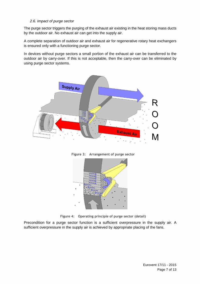
2.6. Impact of purge sector
The purge sector triggers the purging of the exhaust air existing in the heat storing mass ducts
by the outdoor air. No exhaust air can get into the supply air.
A complete separation of outdoor air and exhaust air for regenerative rotary heat exchangers
is ensured only with a functioning purge sector.
In devices without purge sectors a small portion of the exhaust air can be transferred to the
outdoor air by carry-over. If this is not acceptable, then the carry-over can be eliminated by
using purge sector systems.
Figure 3: Arrangement of purge sector
Figure 4: Operating principle of purge sector (detail)
Precondition for a purge sector function is a sufficient overpressure in the supply air. A
sufficient overpressure in the supply air is achieved by appropriate placing of the fans.

Eurovent 17/11 - 2015
Page 8 of 13
Figure 5: Correct pressure potential for installation of purge sector
The purge sector fulfils its function only then when the pressure potential of the supply air is
greater than that of the exhaust air.
Beyond this a correct execution of a purge sector depends on the different construction
principles (sealing systems, manufacturing tolerances, number of revolutions etc.) of different
manufacturers.
Impact of purge sector on EATR and OACF:
Rotary heat exchanger with purge sector = High OACF and low EATR
Rotary heat exchanger without purge sector = Low OACF and high EATR
Figure 6: Influence of the purge sector
2.7. Internal leakage sources and how to decrease the leakages?
Internal leakage occurs when the pressure difference between the two streams is bigger than
zero. It increases with increasing pressure difference.
It is difficult to completely eliminate leakage, but its effect can be reduced by taking the
following actions:
Decrease differential pressure between air streams
Use a stable sealing system
Supply Air
Exhaust Air
Influence of the purge sector
Duct pressure difference 22-11 [Pa]
Eurovent 17/11 - 2015
Page 9 of 13
2.7.1. To decrease the differential pressure by Fan positioning
Fan positioning can be designed to keep pressure difference as low as the system allows. This
method allows getting the lowest leakage available for that system (see section 3.1).
2.7.2. Use a pressure resistant / better / more stable sealing system
Another way to reduce the leakage is to use a more stable sealing system that allows low
leakage even at high pressure differences.
By combining the above mentioned solutions the leakage can be reduced to very low values
and assure a tight system.
3. Design
3.1. Impact of the positioning of fans
The fans can be arranged in four different combinations and every combination has benefits
and disadvantages. The fan arrangement will influence the factors EATR and OACF.
The EATR and OACF are important factors for the assessment of heat exchangers and the
fan arrangement has an influence on both factors. In the examples below the different fan
positions for a system equipped with a rotary heat exchanger will be described. The same
assessments can be given for other types of heat exchangers.
We assume the following:
Heat exchanger pressure drop: 100 Pa
Filter F7 (supply side): 100 Pa
Filter M5 (Extract side): 80 Pa
Available external pressure drop supply side: 300 Pa
Available external pressure drop extract side: 200Pa
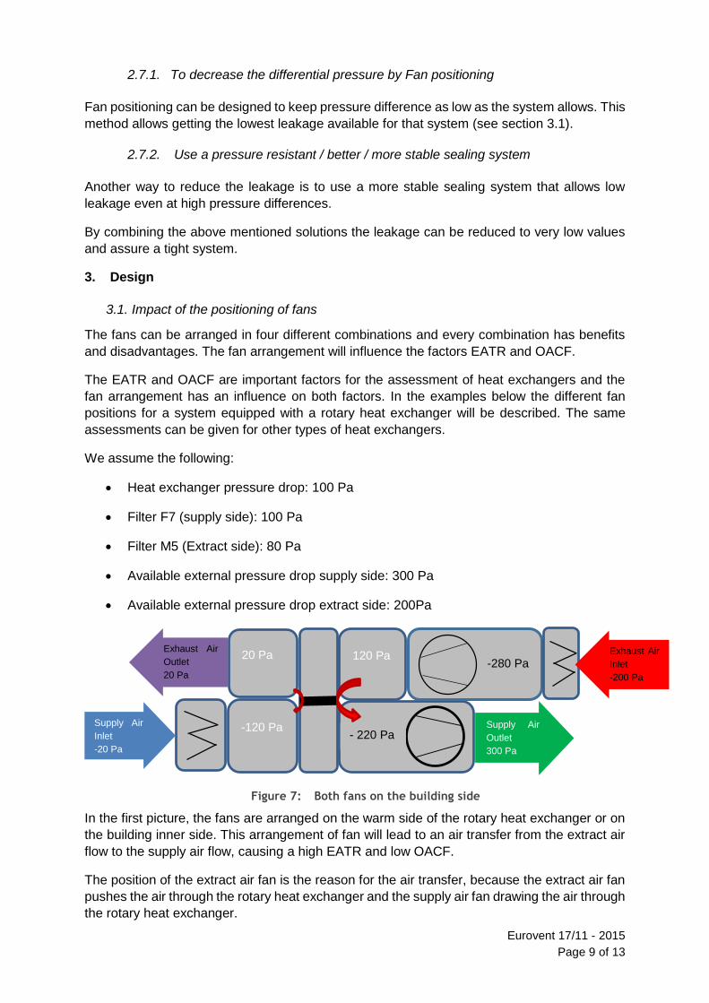
Figure 7: Both fans on the building side
In the first picture, the fans are arranged on the warm side of the rotary heat exchanger or on
the building inner side. This arrangement of fan will lead to an air transfer from the extract air
flow to the supply air flow, causing a high EATR and low OACF.
The position of the extract air fan is the reason for the air transfer, because the extract air fan
pushes the air through the rotary heat exchanger and the supply air fan drawing the air through
the rotary heat exchanger.
- 220 Pa
-280 Pa 20 Pa
-120 Pa
120 Pa Exhaust Air
Inlet
-200 Pa
Supply Air
Outlet
300 Pa
Supply Air
Inlet
-20 Pa
Exhaust Air
Outlet
20 Pa
Eurovent 17/11 - 2015
Page 10 of 13
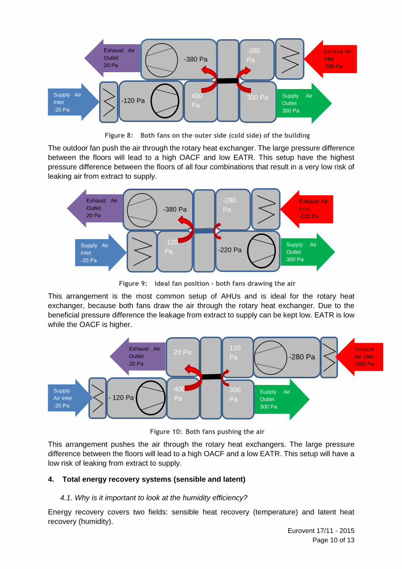
Figure 8: Both fans on the outer side (cold side) of the building
The outdoor fan push the air through the rotary heat exchanger. The large pressure difference
between the floors will lead to a high OACF and low EATR. This setup have the highest
pressure difference between the floors of all four combinations that result in a very low risk of
leaking air from extract to supply.
Figure 9: Ideal fan position - both fans drawing the air
This arrangement is the most common setup of AHUs and is ideal for the rotary heat
exchanger, because both fans draw the air through the rotary heat exchanger. Due to the
beneficial pressure difference the leakage from extract to supply can be kept low. EATR is low
while the OACF is higher.
Figure 10: Both fans pushing the air
This arrangement pushes the air through the rotary heat exchangers. The large pressure
difference between the floors will lead to a high OACF and a low EATR. This setup will have a
low risk of leaking from extract to supply.
4. Total energy recovery systems (sensible and latent)
4.1. Why is it important to look at the humidity efficiency?
Energy recovery covers two fields: sensible heat recovery (temperature) and latent heat
recovery (humidity).
-120 Pa
-380 Pa
300 Pa
-280
Pa
400
Pa
Exhaust Air
Inlet
-200 Pa
Supply Air
Outlet
300 Pa
Supply Air
Inlet
-20 Pa
Exhaust Air
Outlet
20 Pa
-220 Pa
-280
Pa
-120
Pa
Exhaust Air
Inlet
-200 Pa
Supply Air
Outlet
300 Pa
Supply Air
Inlet
-20 Pa
-380 Pa
Exhaust Air
Outlet
20 Pa
- 120 Pa
-280 Pa 20 Pa
Supply Air
Outlet
300 Pa
Exhaust
Air Inlet
-200 Pa
Supply
Air Inlet
-20 Pa
Exhaust Air
Outlet
20 Pa
400
Pa
120
Pa
300
Pa

Eurovent 17/11 - 2015
Page 11 of 13
While most systems only recover temperature some systems are also capable of recovering
the humidity of air. This results in much higher transferred power as humidified air at same
temperature has higher enthalpy. For comparison: Evaporating only 1 kg/h of water into the air
reflects 700W of power (!).
Therefore, recovering temperature and humidity opens an additional field of energy saving.
High efficient humidity recovery opens a new opportunities for energetic and investment
advantages:
In mechanically cooled buildings the needed cooling power can be reduced by up to
50% (depending on conditions and technique) by use of sorption technique. This is
possible because in summertime the humidity transfer dries the outdoor air. Due to this
the cooling section can be reduced as less power is necessary to achieve the same
temperature. This results in lower investment costs with even better air conditions. In
the same time the needed energy is reduced also. This saves not only energy and
money it also protects the environment.
In the wintertime a lot of buildings have to be humidified to have a healthy air condition.
In this case the needed energy for evaporating water or additional heating (due to the
adiabatic cooling effects of the water) can be mostly saved due to the humidity
recovery.
In cases of freezing danger the humidity transfer reduces (and with high efficient
humidity transfer in most cases even avoids) the building of condensate on the extract
air side. Therefore freezing is either not happening or is at least massively reduced. In
this case no capacity reduction of the heat recovery is necessary during the cold period
- the heat exchanger does not freeze.
4.2. Techniques to recover humidity
The most popular systems are:
Regenerative heat exchangers with sorption coating (e.g. sorption wheels)
Plate heat exchangers with humidity transfer
Regenerative heat exchangers with hygroscopic coating (hygroscopic wheels)
Other regenerative heat exchangers (e.g. condensation wheels)
Sorption wheels and plate heat exchangers with humidity transfer are capable of transferring
humidity constantly the whole year through (not only in wintertime).
Hygroscopic wheels are less efficient than sorption wheels during summer time.
Condensation wheels are mainly capable of transferring humidity when condensation occurs
(that is during winter time only). They should therefore only be used for applications without
cooling or humidifying.
5. Literature
[1] ANSI/AHRI: Standard 1060 Standard for Performance Rating of Air to Air Exchangers
for Energy Recovery Ventilation Components – 2013.
[2] ASHRAE: Handbook, Chapter 25.6 – Air to Air Energy Recovery Device.

Eurovent 17/11 - 2015
Page 12 of 13
[3] Eurovent Certita Certification: OM-8-2015 Operational Manual for the Certification of Air
to Air Plate and Tube Heat Exchangers – January 2015.
[4] Eurovent Certita Certification: RS 8/C/001-2015 Rating Standard for the Certification of
Air to Air Plate and Tube Heat Exchangers – January 2015.
[5] Eurovent Certita Certification: OM-10-2015 Operational Manual for the Certification of Air
to Air Regenerative Heat Exchangers – January 2015.
[6] Eurovent Certita Certification: RS 8/C/002-2015 Rating Standard for the Certification of
Air to Air Regenerative Heat Exchangers – January 2015.

Eurovent 17/11 - 2015
Page 13 of 13
ANNEXE A. CALCULATION OF LEAKAGE INDICES AND RECIRCULATION FACTOR
ACCORDING TO VDI 3803/PART 5
A.1. DEFINITIONS
Leakage index extract airflow: 𝐿1 =�̇�11
�̇�11−�̇�1−2=
�̇�11
�̇�1
Leakage index outside airflow: 𝐿2 =�̇�21
�̇�21−�̇�2−1=
�̇�21
�̇�2
where
�̇�1 leakage-free extract airflow
�̇�2 leakage-free outside airflow
�̇�1−2 circulation air leakage from extract airflow to outside air flow
�̇�2−1 short-circuit air leakage from outside airflow to extract air flow
Recirculation factor U: 𝑈 =�̇�1−2
�̇�21−�̇�2−1=
�̇�1−2
�̇�2
Translation table between VDI 3803/Part 5 and this document:
VDI 3803/Part 5 Eurovent
�̇�11 = 𝑞𝑚,11
�̇�22 = 𝑞𝑚,22
�̇�2 = 𝑞𝑚,22,𝑛𝑒𝑡 = 𝑞𝑚,22 ∗ (1 − 𝐸𝐴𝑇𝑅)
�̇�1−2 = 𝑞𝑚,22 ∗ 𝐸𝐴𝑇𝑅
𝑈 =�̇�1−2
�̇�21 − �̇�2−1=
�̇�1−2
�̇�2 =
𝑞𝑚,22 ∗ 𝐸𝐴𝑇𝑅
𝑞𝑚,22,𝑛𝑒𝑡=
𝑞𝑚,22 ∗ 𝐸𝐴𝑇𝑅
𝑞𝑚,22 ∗ (1 − 𝐸𝐴𝑇𝑅)=
𝐸𝐴𝑇𝑅
1 − 𝐸𝐴𝑇𝑅
𝐿1 =�̇�11
�̇�11 − �̇�1−2=
�̇�11
�̇�1 -
𝐿2 =�̇�21
�̇�21 − �̇�2−1=
�̇�21
�̇�2 =
𝑞𝑚21
𝑞𝑚,22,𝑛𝑒𝑡= 𝑓 =
𝑂𝐴𝐶𝐹
1 − 𝐸𝐴𝑇𝑅