guidelines and technical basis - nerc
TRANSCRIPT

Guidelines and Technical Basis
Introduction
The document, “Power Plant and Transmission System Protection Coordination,” published by the NERC System Protection and Control Subcommittee (SPCS) provides extensive general discussion about the protective functions and generator performance addressed within this standard. This document was last revised in July 2010.1
The term, “while maintaining reliable fault protection” in Requirement R1, describes that the Generator Owner (“responsible entity (“Generator Owner”) is to comply with this standard while achieving its desired protection goals. Load-responsive protective relays, as addressed within this standard, may be intended to provide a variety of backup protection functions, both within the generation unit or plant and on the Transmission system, and this standard is not intended to result in the loss of these protection functions. Instead, it is suggested that the responsible entity consider both the requirements within this standard and its desired protection goals, and perform modifications to its protectionve relays or protection philosophies as necessary to achieve both.
For example, if the intended protection purpose is to provide backup protection for a failed Transmission breaker, it may not be possible to achieve this purpose while complying with this standard if a simple mho relay is being used. In this case, it may be necessary to replace the legacy relay with a modern advanced-technology relay that can be set using functions such as load encroachment. It may otherwise be necessary to reconsider whether this is an appropriate method of achieving protection for the failed Transmission breaker, and whether this protection can be better provided by, for example, applying a breaker failure relay with a transfer trip system.
Requirement R1 establishes that the responsible entity must understand the criteria and applicationapplications of Table 1, Relay Loadability Evaluation Criteria (“Table 1”),”) in determining the settings that it must install onapply to each of its load-responsive protective relays to achieve the requiredprevent an unnecessary trip of its generator performance during the transientsystem conditions anticipated by this standard.
Applicability
The drafting team recognizes that some Generator Owners own an interconnection facility (in some cases labeled a “transmission Facility” or “generator leads”) between the generator and the interface with the portion of the BES where Transmission Owners take over the ownership. In these cases, the Generator Owners own sole-use Facilities that are connected to the boundary of the interconnected system. Load-responsive protective relays applied by the Generator Owner at the terminals of these Facilities to protect these interconnection Facilities are included in the scope of this standard.
1 http://www.nerc.com/docs/pc/spctf/Gen%20Prot%20Coord%20Rev1%20Final%2007-30-2010.pdf

Draft 2: Guidelines and Technical Basis (PRC-025-1) 2 of 47
Synchronous Generator Performance
When a synchronous generator experiences a depressed voltage, the generator will respond by increasing its Reactive Power output to support the generator terminal voltage. This operating condition, known as “field-forcing,” results in the Reactive Power output exceeding the steady-state capability of the generator and the resultant increase in apparent power may result in operation of generation system load-responsive generator protective functions,relays if they are not set to consider this operating condition. The ability of the generating unit to withstand the increased Reactive Power output during field-forcing is limited by the field winding thermal withstand capability. The excitation limiter maywill respond to begin reducing the level of field-forcing in as little as one second, but may take much longer, depending on the level of field-forcing andgiven the characteristics and application of the excitation system. Since this time may be longer than the time-delay of the generator backup protection, it is important to evaluate load-responsive protective relay, it is important to evaluate the loadability to prevent its operation for this condition during which the generator is not at risk of thermal damage.
The generator bus voltage during field-forcing will be higher than the high-side voltage due to the voltage drop across the generator step-up transformer. When the relay voltage is supplied from the generator bus, it is necessary to assess loadability using the generator bus voltage. The criteria established within Table 1, are based on 0.85 per unit of Transmission system nominal voltage. This voltage was widely observed during the events of August 14, 2003, and was determined during the analysis of the events to represent a condition from which the System may have recovered, had not other, undesired, behavior occurred.
The dynamic load levels specified in Table 1 under column Pick Up“Pickup Setting cCriteria,” are representative of the maximum expected apparent power during field-forcing with the Transmission system voltage at 0.85 per unit, for example, at the high-side of the generator step-up transformer. These values are based on values recorded duringrecords from the events leading to the August 14, 2003 blackout, other subsequent sSystem events, and simulations of generating unit responses to similar conditions. Based on these observations, the specified load operating points are believed tocriteria represent conservative, but achievable levels of Reactive Power output of the generator with a 0.85 per unit high-side voltage at the point of interconnection.
The dynamic load levels were validated by simulating the response of synchronous generating units to depressed Transmission system voltages for 67 different generating units. The generating units selected for the simulations represented a broad range of generating unit and excitation system characteristics as well as a range of Transmission system interconnection characteristics. The simulations confirmed, for units operating at or near the maximum Real Power output, that it is possible to achieve a Reactive Power output of 1.5 times the rated Real Power output when the Transmission system voltage is depressed to 0.85 per unit. While the simulations demonstrated that all generating units may not be capable of this level of Reactive Power output, the simulations confirmed that approximately 20% percent of the units modeled in the simulations could achieve these levels. On the basis of these levels, Table 1, Options 11a (0.95 per unit) and 2,1b (0.85 per unit), for example, are based on relatively simple, but conservative calculations. of the high-side nominal voltage. In recognition that not all units are capable of achieving this level of output, Option 3, for example,1c (simulation) was developed to allow anthe responsible entity to simulate the output of a generating unit when the simple calculation is too conservativenot adequate to achieve the desired protective functionrelay setting.

Draft 2: Guidelines and Technical Basis (PRC-025-1) 3 of 47
Asynchronous Generator Performance
Asynchronous generators, however, do not have excitation systems and will not respond to a Ddisturbance with the same magnitude of apparent power that a synchronous generator will respond. Asynchronous generators, though, will support the system during a disturbance. Inverter-based generators will provide Real Power and Reactive Power (depending on the installed capability and regional grid code requirements) and may even provide a faster Reactive Power response than a synchronous generator. The magnitude of this response may slightly exceed the steady-state capability of the inverter but only for a short duration before a crowbar function will activate. Although induction generators will not inherently supply Reactive Power, induction generator installations may include static and/or dynamic reactive devices, depending on regional grid code requirements. TheyThese devices also may provide Real Power during a voltage disturbance. Thus, tripping asynchronous generators may exacerbate a disturbance.
Inverters, including wind turbines (i.e., Types 3 and 4) and photovoltaic solar, are commonly available with 0.90 power factor capability. This calculates to an apparent power magnitude of 1.11 per unit of rated megawatts (MW).
Similarly, induction generator installations, including Type 1 and Type 2 wind turbines, often include static and/or dynamic reactive devices to meet grid code requirements and may have apparent power output similar to inverter-based installations; therefore, it is appropriate to use the criteria established in the Table 1, (i.e.g., Option., Options 4, 5, 6, 10, 11, 12, 17, 18, and 19), for inductionasynchronous generator installations.
Synchronous Generator Simulation Criteria
The responsible entity who elects to determine the synchronous generator performance on which to base relay settings may simulate the response of a generator by lowering the Transmission system voltage on the high-side of the generator step-up transformer. This can be simulated by means such as modeling the connection of a shunt reactor on the Transmission system to lower the generator step-up transformer high-side voltage to 0.85 per unit prior to field-forcing. The resulting step change in voltage is similar to the sudden voltage depression observed in parts of the Transmission system on August 14, 2003. The initial condition for the simulation should represent the generator at 100 percent of the maximum gross Real Power capability in megawatts as reported to the Planning Coordinator or Transmission Planner.
Phase Distance Relay (Options 1-4– Directional Toward Transmission System (21)
Generator phase distance relays that are directional toward the Transmission system, whether applied for the purpose of primary or backup generator step-up transformer protection, external system backup protection, or both, were noted during analysis of the August 14, 2003 disturbance event to have unnecessarily or prematurely tripped a number of generation units or plants, contributing to the scope of that disturbance. Specifically, eight generators are known to have been tripped by this protection function. The Options 1 through 4 These options establish criteria for phase distance relays that are directional toward the Transmission system to help
Draft 2: Guidelines and Technical Basis (PRC-025-1) 4 of 47
assure that generators, to the degree possible, will provide System support during disturbances in an effort to minimize the scope of those disturbances.
Phase distance protectionThe phase distance relay that is directional toward the Transmission system measures impedance derived from the quotient of generator terminal voltage divided by generator stator current. When phase distance protection is applied, its function is to provide backup protection for system faults that have not been cleared by Transmission system circuit breakers via their protective relays.
Section 4.6.1.1 of IEEE C37.102-2006, “Guide for AC Generator Protection,” describes the purpose of this protection as follows (emphasis added):
“The distance relay applied for this function is intended to isolate
the generator from the power system for a fault whichthat is not
cleared by the transmission line breakers. In some cases this relay
is set with a very long reach. A condition whichthat causes the
generator voltage regulator to boost generator excitation for a
sustained period that may result in the system apparent impedance,
as monitored at the generator terminals, to fall within the
operating characteristics of the distance relay. Generally, a
distance relay setting of 150% to 200% of the generator MVA
rating at its rated power factor (sic: This setting can be re-stated in terms of ohms as 0.66 – 0.50 per unit ohms on the machine base.) has been shown to provide good coordination for stable swings,
system faults involving infeedin-feed, and normal loading
conditions. However, this setting may also result in failure of the
relay to operate for some line faults where the line relays fail to
clear. It is recommended that the setting of these relays be
evaluated between the generator protection engineers and the
system protection engineers to optimize coordination while still
protecting the turbine -generator. Stability studies may be needed
to help determine a set point to optimize protection and
coordination. Modern excitation control systems include
overexcitation limiting and protection devices to protect the
generator field, but the time delay before they reduce excitation is
several seconds. In distance relay applications for which the
voltage regulator action could cause an incorrect trip,
consideration should be given to reducing the reach of the relay
and/or coordinating the tripping time delay with the time delays of
the protective devices in the voltage regulator. Digital
multifunction relays equipped with load encroachment
blindersbinders [sic] can prevent misoperation for these
conditions. Within its operating zone, the tripping time for this
relay must coordinate with the longest time delay for the phase
distance relays on the transmission lines connected to the generating substation bus. With the advent of multifunction
generator protection relays, it is becoming more common to use
two-phase distance zones. In this case, the second zone would be

Draft 2: Guidelines and Technical Basis (PRC-025-1) 5 of 47
set as previously described above. When two zones are applied for
backup protection, the first zone is typically set to see the
substation bus (120% of the generator step-upGSU transformer).
This setting should be checked for coordination with the zone-1
element on the shortest line off of the bus. YourThe normal zone-2
time-delay criteria would be used to set the delay for this element.
Alternatively, zone-1 can be used to provide high-speed protection
for phase faults, in addition to the normal differential protection,
in the generator and isolated-phase bus with partial coverage of
the generator step-upGSU transformer. For this application, the
element would typically be set to 50% of the transformer
impedance with little or no intentional time delay. It should be
noted that it is possible that this element can operate on an out-of-
step power swing condition and provide misleading targeting.”
Table 1, Options 1, 2, and 3, are provided for assessing loadability for synchronous generators. The generator-side voltage during field forcing will be higher than the high-side voltage due to the voltage drop resulting from the Reactive Power flow through the generator step-up transformer. Since the relay voltage is supplied from the generator bus, it is necessary to assess loadability using the generator-side voltage.
Option 1 accounts for the voltage drop across the generator step-up transformer using a conservative estimate of the generator-side voltage. This is based on referring a 0.95 per unit system nominal voltage at the high-side terminals of the generator step-up transformer through the turns ratio.
Option 2 uses a calculated generator bus voltage corresponding to 0.85 per unit nominal voltage on the high-side terminals of the generator step-up transformer. The actual generator bus voltage may be higher depending on the generator step-up transformer impedance and the actual Reactive Power achieved. This option accounts for the voltage drop through the generator step-up transformer, including the turns-ratio and impedance.
Option 3 uses a simulated generator bus voltage corresponding to 0.85 per unit nominal voltage on the high-side terminals of the generator step-up transformer. The responsible entity must perform simulations to determine the actual performance of its generator. The responsible entity that elects to determine the synchronous generator performance on which to base phase distance relay settings may simulate the response of a generator to depressed Transmission system by lowering the Transmission system voltage on the high-side of the generator step-up transformer. This can be simulated by means such as modeling switching of a shunt reactor on the Transmission system to lower the generator step-up transformer high-side voltage to 0.85 per unit prior to field forcing. The resulting step change in voltage is similar to the sudden voltage depression observed in parts of the Transmission system on August 14, 2003. The initial condition for the simulation should represent the generator holding the assigned voltage schedule while at 100% of the maximum seasonal gross Real Power capability value as reported to the Planning Coordinator.
Option 4 is based on a 1.0 per unit system nominal voltage at the high-side terminals of the generator step-up transformer. Since the relay voltage is supplied from the generator bus, it is necessary to assess loadability using the generator-side voltage. Since asynchronous generators

Draft 2: Guidelines and Technical Basis (PRC-025-1) 6 of 47
do not produce as much reactive power as synchronous generators, the voltage rise due to reactive power flow through the generator step-up transformer is not as significant. Therefore, the generator bus voltage can be conservatively estimated by reflecting the high side nominal voltage to the generator side based on the generator step-up transformer’s turns ratio. The aggregate megavoltampere (MVA) output is determined by summing the total nameplate MW and megavoltampere-reactive (Mvar) capability of the generation equipment behind the relay. This should also include any static or dynamic reactive power devices that contribute to the power flow through the relay.
If a mho phase distance relay that is directional toward the Transmission system cannot be set to maintain reliable protection and also meet the criteria in accordance with Table 1, there may be other methods available to do both, such as application of blinders to the existing relays, implementation of lenticular characteristic relays, application of offset mho relays, or implementation of load encroachment characteristics. Some methods are better suited to improving loadability around a specific operating point, while others improve loadability for a wider area of potential operating points in the R-X plane. The operating point for a stressed System condition can vary due to the pre-event system conditions, severity of the initiating event, and generator characteristics such as Reactive Power capability (i.e., field forcing). .
For this reason, it is important to consider the potential implications of revising the shape of the relay characteristic to obtain a longer relay reach, as this practice may restrict the capability of the generating unit when operating at a Real Power output level other than 100 percent of the maximum Real Power capability. The examples in Appendix E “of the Power Plant and Transmission System Protection Coordination,” published by the NERC System Protection and Control Subcommittee, technical reference document illustrate the potential for encroaching on the generating unit capability.
If an entity is unable to meet the criteria established within Table 1, while maintaining reliable protection, the entity will need to utilize different protective relays or protection philosophies such that both goals can be met.
Generator Phase
Phase Time Overcurrent Relay (51)
See section 3.9.2 of the Power Plant and Transmission System Protection Coordination technical reference document for a detailed discussion of this protection function. Note that the setting criteria established within these options differ from section 3.9.2 of the Power Plant and Transmission System Protection Coordination technical reference document. Rather than establishing a uniform setting threshold of 200 percent of the generator MVA rating at rated power factor for all applications, the setting criteria are based on the maximum expected generator output based on whether the generator operates synchronous or asynchronous.
Phase Time Overcurrent Relay – Voltage-Restrained (Options 5-851V-R)
Generator Phase time overcurrent voltage-restrained phase overcurrent relays, (51V-R), which change their sensitivity as a function of voltage, whether applied for the purpose of primary or backup generator step-up transformer protection, for external system phase backup protection, or

Draft 2: Guidelines and Technical Basis (PRC-025-1) 7 of 47
both, were noted, during analysis of the August 14, 2003 disturbance event to have unnecessarily or prematurely tripped a number of generation units or plants, contributing to the scope of that disturbance. Specifically, 20 generators are known to have been tripped by Voltage Restrainedvoltage-restrained and Voltage Controlledvoltage-controlled protection functions together. These protective functions are variably referred to by IEEE function numbers 51V, 51R, 51VR, 51V/R, 51V-R, or other terms. See section 3.10 of the Power Plant and Transmission System Protection Coordination technical reference document for a detailed discussion of this protection function.
Table 1, Options 5 through 8, establish criteria for phase
Phase Time Overcurrent Relay – Voltage Controlled (51V-C)
Phase time overcurrent voltage-controlled relays which change their sensitivity(51V-C), enabled as a function of voltage to help assure that generators, to the degree possible, will provide system support during disturbances in an effort to minimize the scope of those disturbances. These devices, are variably referred to by IEEE function numbers (51V), (51R), (51VR), (, 51C, 51VC, 51V/R), (C, 51V-R),C, or other terms. The criteria provided for these relays are very similar to those provided for phase distance relays in Options 1 through 4. See clausesection 3.10 of “the Power Plant and Transmission System Protection Coordination,” published by the NERC System Protection and Control Subcommittee (SPCS) technical reference document for a detailed discussion of this protection function.
Refer to the discussion under Option 4 technical basis concerning asynchronous and inverter based generation.
Generator Phase Directional Time Overcurrent Relays – Voltage Controlled (Option
9Relay – Directional Toward Transmission System (67)
Generator voltage-controlled overcurrent relays, enabled as a function of voltage, are applied for the purpose of primary or backup generator step-up transformer protection, for external system phase backup protection, or both, were noted, during analysis of the August 14, 2003 disturbance event to have unnecessarily or prematurely tripped a number of generation plants, contributing to the scope of that disturbance. Specifically, 20 generators are known to have been tripped by Voltage Restrained and Voltage Controlled protection functions together, and many other generators were tripped by unknown protection functions.
Table 1, Option 9, establishes criterion for phase overcurrent relays which are enabled as a function of voltage to help assure that generators, to the degree possible, will provide system support during disturbances in an effort to minimize the scope of those disturbances. These devices are variably referred to by IEEE function numbers (51V), (51C), (51VC), (51V/C), (51V-C), or other terms. See clausesection 3.109.2 of “the Power Plant and Transmission System Protection Coordination,” published by the NERC System Protection and Control Subcommittee technical reference document for a detailed discussion of thisthe phase time overcurrent protection function. The basis for setting directional and non-directional time overcurrent relays are similar. Note that the setting criteria for a voltage control setting of lessestablished within these options differ from section 3.9.2 of the Power Plant and Transmission System Protection Coordination technical reference document. Rather than 0.75

Draft 2: Guidelines and Technical Basis (PRC-025-1) 8 of 47
per unit of the nominalestablishing a uniform setting threshold of 200 percent of the generator MVA rating at rated power factor for all applications, the setting criteria are based on the maximum expected generator voltage is output based on whether the generator operates synchronous or asynchronous.

Draft 2: Guidelines and Technical Basis (PRC-025-1) 9 of 47
Table 1, Options
Introduction
The margins in these options are based on guidance found in “the Power Plant and Transmission System Protection Coordination technical reference document. The generator bus voltage during field-forcing will be higher than the high-side voltage due to the voltage drop across the generator step-up transformer. When the relay voltage is supplied from the generator bus, it is necessary to assess loadability using the generator bus voltage.
Synchronous Generators Phase Distance Relay – Directional Toward Transmission System
(21) (Options 1a, 1b, and 1c)
Table 1, Options 1a, 1b, and 1c, are provided for assessing loadability for synchronous generators applying phase distance relays that are directional toward the Transmission system. These margins are based on guidance found in section 3.1 of the Power Plant and Transmission System Protection Coordination technical reference document.
Option 1a calculates a generator bus voltage corresponding to 0.95 per unit nominal voltage on the high-side terminals of the generator step-up transformer. The generator bus voltage is calculated by multiplying a 0.95 per unit system nominal voltage at the high-side terminals of the generator step-up transformer times the turns ratio of the generator step-up transformer (excluding the impedance). This is the simplest calculation that approximates the stressed system conditions.
Option 1b calculates the generator bus voltage corresponding to 0.85 per unit nominal voltage on the high-side terminals of the generator step-up transformer. The voltage drop across the generator step-up transformer is calculated based on a 0.85 per unit system nominal voltage at the high-side terminals of the generator step-up transformer and accounts for the turns ratio and impedance of the generator step-up transformer. The actual generator bus voltage may be higher depending on the generator step-up transformer impedance and the actual Reactive Power achieved. ,” published by the NERC SPCS. This calculation is a more involved, more precise setting of the impedance element than Option 1a.
Option 1c simulates the generator bus voltage corresponding to 0.85 per unit nominal voltage on the high-side terminals of the generator step-up transformer. Using simulation is a more involved, more precise setting of the impedance element overall.
For Options 1a and 1b, the impedance element is set less than the calculated impedance derived from 115% of: the Real Power output of 100 percent of the maximum gross MW capability reported to the Planning Coordinator or Transmission Planner, and Reactive Power output that equates to 150 percent of the MW value, derived from the nameplate MVA rating at rated power factor.
For Option 1c, the impedance element is set less than the calculated impedance derived from 115 percent of: the Real Power output of 100 percent of the maximum gross MW capability reported to the Planning Coordinator or Transmission Planner, and Reactive Power output that equates to 100 percent of the maximum gross Mvar output determined by simulation.

Draft 2: Guidelines and Technical Basis (PRC-025-1) 10 of 47
Synchronous Generators Phase Time Overcurrent Relay – Voltage-Restrained (51V-R)
(Options 2a, 2b, and 2c)
Table 1, Options 2a, 2b, and 2c, are provided for assessing loadability for synchronous generators applying phase time overcurrent relays which change their sensitivity as a function of voltage (“voltage-restrained”). These margins are based on guidance found in section 3.10 of the Power Plant and Transmission System Protection Coordination technical reference document.
Option 2a calculates a generator bus voltage corresponding to 0.95 per unit nominal voltage on the high-side terminals of the generator step-up transformer. The generator bus voltage is calculated by multiplying a 0.95 per unit system nominal voltage at the high-side terminals of the generator step-up transformer times the turns ratio of the generator step-up transformer (excluding the impedance). This is the simplest calculation that approximates the stressed system conditions.
Option 2b calculates the generator bus voltage corresponding to 0.85 per unit nominal voltage on the high-side terminals of the generator step-up transformer. The voltage drop across the generator step-up transformer is calculated based on a 0.85 per unit system nominal voltage at the high-side terminals of the generator step-up transformer and accounts for the turns ratio and impedance of the generator step-up transformer. The actual generator bus voltage may be higher depending on the generator step-up transformer impedance and the actual Reactive Power achieved. This calculation is a more involved, more precise setting of the overcurrent element than Option 2a.
Option 2c simulates the generator bus voltage corresponding to 0.85 per unit nominal voltage on the high-side terminals of the generator step-up transformer. Using simulation is a more involved, more precise setting of the overcurrent element overall.
For Options 2a and 2b, the overcurrent element is set greater than 115 percent of the calculated current derived from: the Real Power output of 100 percent of the maximum gross MW capability reported to the Planning Coordinator or Transmission Planner, and Reactive Power output that equates to 150 percent of the MW value, derived from the nameplate MVA rating at rated power factor.
For Option 2c, the overcurrent element is set greater than the calculated current derived from 115 percent of: the Real Power output of 100 percent of the maximum gross MW capability reported to the Planning Coordinator or Transmission Planner, and Reactive Power output that equates to 100 percent of the maximum gross Mvar output determined by simulation.
Synchronous Generators Phase Time Overcurrent Relay – Voltage Controlled (51V-C)
(Option 3)
Table 1, Option 3, is provided for assessing loadability for synchronous generators applying phase time overcurrent relays which are enabled as a function of voltage (“voltage-controlled”). These margins are based on guidance found in section 3.10 of the Power Plant and Transmission System Protection Coordination technical reference document.
Option 3 calculates the generator bus voltage corresponding to 1.0 per unit nominal voltage on the high-side terminals of the generator step-up transformer. The generator bus voltage is calculated by multiplying a 1.0 per unit system nominal voltage at the high-side terminals of the generator step-up transformer times the turns ratio of the generator step-up transformer

Draft 2: Guidelines and Technical Basis (PRC-025-1) 11 of 47
(excluding the impedance). This is a simple calculation that approximates the stressed system conditions.
For Option 3, the voltage control setting is set less than 75 percent of the calculated generator bus voltage. The voltage setting must be set such that the function (e.g., 51V-C) will not trip under extreme emergency conditions as the time overcurrent function will be set less than generator full load current. Relays enabled as a function of voltage isare indifferent as to the current setting, and this option simply requires that the relays not respond for the depressed voltage.
Refer to the discussion under
Asynchronous Generators Phase Distance Relay – Directional Toward Transmission
System (21) (Option 4 technical basis concerning)
Table 1, Option 4 is provided for assessing loadability for asynchronous and invertergenerators applying phase distance relays that are directional toward the Transmission system. These margins are based on guidance found in section 3.1 of the Power Plant and Transmission System Protection Coordination technical reference document.
Option 4 calculates the generator bus voltage corresponding to 1.0 per unit nominal voltage on the high-side terminals of the generator step-up transformer. The generator bus voltage is calculated by multiplying a 1.0 per unit system nominal voltage at the high-side terminals of the generator step-up transformer times the turns ratio of the generator step-up transformer (excluding the impedance). This is a simple calculation that approximates the stressed system conditions.
Since the relay voltage is supplied from the generator bus, it is necessary to assess loadability using the generator-side voltage. Asynchronous generators do not produce as much reactive power as synchronous generators; the voltage drop due to reactive power flow through the generator step-up transformer is not as significant. Therefore, the generator bus voltage can be conservatively estimated by reflecting the high-side nominal voltage to the generator-side based on the generator step-up transformer’s turns ratio.
For Option 4, the impedance element is set less than the calculated impedance derived from 130 percent of the maximum aggregate nameplate megavoltampere (MVA) output at rated power factor including the Mvar output of any static or dynamic reactive power devices. This is determined by summing the total nameplate MW and Mvar capability of the generation equipment behind the relay and any static or dynamic reactive power devices that contribute to the power flow through the relay.
Asynchronous Generators Phase Time Overcurrent Relay – Voltage-Restrained (51V-R)
(Option 5)
Table 1, Option 5 is provided for assessing loadability for asynchronous generators applying phase time overcurrent relays which change their sensitivity as a function of voltage (“voltage-restrained”). These margins are based on guidance found in section 3.10 of the Power Plant and Transmission System Protection Coordination technical reference document.
Option 5 calculates the generator bus voltage corresponding to 1.0 per unit nominal voltage on the high-side terminals of the generator step-up transformer. The generator bus voltage is

Draft 2: Guidelines and Technical Basis (PRC-025-1) 12 of 47
calculated by multiplying a 1.0 per unit system nominal voltage at the high-side terminals of the generator step-up transformer times the turns ratio of the generator step-up transformer (excluding the impedance). This is a simple calculation that approximates the stressed system conditions.
Since the relay voltage is supplied from the generator bus, it is necessary to assess loadability using the generator-side voltage. Asynchronous generators do not produce as much reactive power as synchronous generators; the voltage drop due to reactive power flow through the generator step-up transformer is not as significant. Therefore, the generator bus voltage can be conservatively estimated by reflecting the high-side nominal voltage to the generator-side based on the generator step-up transformer’s turns ratio.
For Option 5, the overcurrent element is set greater than 130 percent of the calculated current derived from the maximum aggregate nameplate megavoltampere (MVA) output at rated power factor including the Mvar output of any static or dynamic reactive power devices. This is determined by summing the total nameplate MW and Mvar capability of the generation equipment behind the relay and any static or dynamic reactive power devices that contribute to the power flow through the relay.
Asynchronous Generator Phase Time Overcurrent Relays – Voltage Controlled (51V-C)
(Option 6)
Table 1, Option 6, is provided for assessing loadability for asynchronous generators applying phase time overcurrent relays which are enabled as a function of voltage (“voltage-controlled”). These margins are based on guidance found in section 3.10 of the Power Plant and Transmission System Protection Coordination technical reference document.
Option 6 calculates the generator bus voltage corresponding to 1.0 per unit nominal voltage on the high-side terminals of the generator step-up transformer. The generator bus voltage is calculated by multiplying a 1.0 per unit system nominal voltage at the high-side terminals of the generator step-up transformer times the turns ratio of the generator step-up transformer (excluding the impedance). This is a simple calculation that approximates the stressed system conditions.
For Option 6, the voltage control setting is set less than 75 percent of the calculated generator bus voltage. The voltage setting must be set such that the function (e.g., 51V-C) will not trip under extreme emergency conditions as the time overcurrent function will be set less than generator full load current. Relays enabled as a function of voltage are indifferent as to the current setting, and this option simply requires that the relays not respond for the depressed voltage.
Generator Step-up Transformer Phase Time Overcurrent Relay (Options 10-
12(Synchronous Generators) Phase Distance Relays – Directional Toward Transmission
System (21) (Option 7a, 7b, and 7c)
The Federal Energy Regulatory Commission, in FERC Order No. 733, paragraph 104, directs that NERC address relay loadability for protective relays applied on generator step-up transformers. Table 1, Options 10 through 12, establish criteria for the generator protective
Draft 2: Guidelines and Technical Basis (PRC-025-1) 13 of 47
relays to prevent the generator step-up transformer phase time overcurrent relays from operating during the dynamic conditions anticipated by this standardThese margins are based on guidance found in section 3.1 of the Power Plant and Transmission System Protection Coordination technical reference document.
The stressed system conditions, anticipated by Options 10 through 12, reflect a 0.85 per unit Transmission system voltage; therefore, establishes that the ampere value used for applying the generator step-up transformer phase time overcurrent relay be calculated from the apparent power addressed within the Table 1, with application of a 0.85 per unit Transmission system voltage.
Options 107a, 7b, and 11 apply to7c, are provided for assessing loadability for generator step-up transformers connected to applying phase distance relays that are directional toward the Transmission system on synchronous generators. Option 12 only applies to generator step-up transformers connected to asynchronous generators (including inverter-based installations). that are connected to the generator-side of the generator step-up transformer of a synchronous generator.
Please see clauseOption 7a calculates a generator bus voltage corresponding to 0.95 per unit nominal voltage on the high-side terminals of the generator step-up transformer. The generator bus voltage is calculated by multiplying a 0.95 per unit system nominal voltage at the high-side terminals of the generator step-up transformer times the turns ratio of the generator step-up transformer (excluding the impedance). This is the simplest calculation that approximates the stressed system conditions.
Option 7b calculates the generator bus voltage corresponding to 0.85 per unit nominal voltage on the high-side terminals of the generator step-up transformer. The voltage drop across the generator step-up transformer is calculated based on a 0.85 per unit system nominal voltage at the high-side terminals of the generator step-up transformer and accounts for the turns ratio and impedance of the generator step-up transformer. The actual generator bus voltage may be higher depending on the generator step-up transformer impedance and the actual Reactive Power achieved. This calculation is a more involved, more precise setting of the impedance element than Option 7a.
Option 7c simulates the generator bus voltage corresponding to 0.85 per unit nominal voltage on the high-side terminals of the generator step-up transformer. Using simulation is a more involved, more precise setting of the overcurrent element overall.
For Options 7a and 7b the impedance element is set less than the calculated impedance derived from 115 percent of: the Real Power output of 100 percent of the aggregate generation MW capability reported to the Planning Coordinator or Transmission Planner, and Reactive Power output that equates to 150 percent of the aggregate generation MW value, derived from the nameplate MVA rating at rated power factor.
For Option 7c, the impedance element is set less than the calculated impedance derived from 115 percent of: the Real Power output of 100 percent of the aggregate generation MW capability reported to the Planning Coordinator or Transmission Planner, and Reactive Power output that equates to 100 percent of the maximum gross Mvar output determined by simulation.

Draft 2: Guidelines and Technical Basis (PRC-025-1) 14 of 47
Generator Step-up Transformer (Synchronous Generators) Phase Time Overcurrent Relay
(51) (Options 8a, 8b and 8c)
The Federal Energy Regulatory Commission, in FERC Order No. 733, paragraph 104, directs that NERC address relay loadability for protective relays applied on generator step-up transformers.
Note that the setting criteria established within these options differ from section 3.9.2 of “the Power Plant and Transmission System Protection Coordination,” published by the NERC System Protection and Control Subcommittee for a detailed discussion of this protection function. However, the setting criteria established within Options 10-12 differ from that suggested in this paper. technical reference document. Rather than establishing a uniform setting threshold of 200% percent of the generator MVA rating at rated power factor for all applications, the setting criteria are based on the maximum expected generator output.
Table 1, Options 8a, 8b, and 8c, are provided for assessing loadability for generator step-up transformers applying phase time overcurrent relays on synchronous generators that are connected to the generator-side or high-side of the generator step-up transformer of a synchronous generator.
Option 8a calculates a generator bus voltage corresponding to 0.95 per unit nominal voltage on the high-side terminals of the generator step-up transformer. The generator bus voltage is calculated by multiplying a 0.95 per unit system nominal voltage at the high-side terminals of the generator step-up transformer times the turns ratio of the generator step-up transformer (excluding the impedance). This is the simplest calculation that approximates the stressed system conditions.
Option 8b calculates the generator bus voltage corresponding to 0.85 per unit nominal voltage on the high-side terminals of the generator step-up transformer. The voltage drop across the generator step-up transformer is calculated based on whether the generator operates synchronous or asynchronousa 0.85 per unit system nominal voltage at the high-side terminals of the generator step-up transformer and accounts for the turns ratio and impedance of the generator step-up transformer. The actual generator bus voltage may be higher depending on the generator step-up transformer impedance and the actual Reactive Power achieved. This calculation is a more involved, more precise setting of the impedance element than Option 8a.
Refer to the discussion under Option 4 technical basis concerning asynchronous8c simulates the generator bus voltage corresponding to 0.85 per unit nominal voltage on the high-side terminals of the generator step-up transformer. Using simulation is a more involved, more precise setting of the overcurrent element overall.
For Options 8a and inverter based8b, the overcurrent element is set greater than 115 percent of the calculated current derived from: the Real Power output of 100 percent of the aggregate generation MW capability reported to the Planning Coordinator or Transmission Planner, and Reactive Power output that equates to 150 percent of the aggregate generation MW value, derived from the nameplate MVA rating at rated power factor.
For Option 8c, the overcurrent element is set greater than 115 percent of the calculated current derived from: the Real Power output of 100 percent of the aggregate generation MW capability reported to the Planning Coordinator or Transmission Planner, and Reactive Power output that equates to 100 percent of the maximum gross Mvar output determined by simulation.

Draft 2: Guidelines and Technical Basis (PRC-025-1) 15 of 47
Generator Step-up Transformer (Synchronous Generators) Phase DistanceDirectional
Time Overcurrent Relay – Directional Toward Transmission System (67) (Options 13, 14,
15,9a, 9b and 169c)
The The Federal Energy Regulatory Commission, in FERC Order No. 733, paragraph 112104, directs that NERC address relay loadability for protective relays applied for system backup protection. In paragraph 114, FERC further explains that their concern applies whetheron generator step-up transformers. Note that the setting criteria established within these options differ from section 3.9.2 of the Power Plant and Transmission System Protection Coordination technical reference document. Rather than establishing a uniform setting threshold of 200 percent of the generator MVA rating at rated power factor for all applications, the setting criteria are based on the maximum expected generator output.
Table 1, Options 9a, 9b, and 9c, are provided for assessing loadability for generator step-up transformers applying phase directional time overcurrent relays directional toward the Transmission System that are connected to the generator-side of the generator step-up transformer of a synchronous generator.
Option 9a calculates a generator bus voltage corresponding to 0.95 per unit nominal voltage on the high-side terminals of the generator step-up transformer. The generator bus voltage is calculated by multiplying a 0.95 per unit system nominal voltage at the high-side terminals of the generator step-up transformer times the turns ratio of the generator step-up transformer (excluding the impedance). This is the simplest calculation that approximates the stressed system conditions.
Option 9b calculates the generator bus voltage corresponding to 0.85 per unit nominal voltage on the high-side terminals of the generator step-up transformer. The voltage drop across the generator step-up transformer is calculated based on a 0.85 per unit system nominal voltage at the high-side terminals of the generator step-up transformer and accounts for the turns ratio and impedance of the generator step-up transformer. The actual generator bus voltage may be higher depending on the generator step-up transformer impedance and the actual Reactive Power achieved. This calculation is a more involved, more precise setting of the impedance element than Option 9a.
Option 9c simulates the generator bus voltage corresponding to 0.85 per unit nominal voltage on the high-side terminals of the generator step-up transformer. Using simulation is a more involved, more precise setting of the overcurrent element overall.
For Options 9a and 9b, the overcurrent element is set greater than 115 percent of the calculated current derived from: the Real Power output of 100 percent of the aggregate generation MW capability reported to the Planning Coordinator or Transmission Planner, and Reactive Power output that equates to 150 percent of the aggregate generation MW value, derived from the nameplate MVA rating at rated power factor.
For Option 9c, the overcurrent element is set greater than 115 percent of the calculated current derived from: the Real Power output of 100 percent of the aggregate generation MW capability reported to the Planning Coordinator or Transmission Planner, and Reactive Power output that equates to 100 percent of the maximum gross Mvar output determined by simulation.

Draft 2: Guidelines and Technical Basis (PRC-025-1) 16 of 47
Generator Step-up Transformer (Asynchronous Generators) Phase Distance Relay –
Directional Toward Transmission System (21) (Option 10)
Table 1, Option 10 is provided for assessing loadability for generator step-up transformers applying phase distance relays that are directional toward the Transmission System that are connected to the generator-side of the generator step-up transformer of an asynchronous generator. These margins are based on guidance found in section 3.1 of the Power Plant and Transmission System Protection Coordination technical reference document.
Option 10 calculates the generator bus voltage corresponding to 1.0 per unit nominal voltage on the high-side terminals of the generator step-up transformer. The generator bus voltage is calculated by multiplying a 1.0 per unit system nominal voltage at the high-side terminals of the generator step-up transformer times the turns ratio of the generator step-up transformer (excluding the impedance). This is a simple calculation that approximates the stressed system conditions.
Since the relay voltage is supplied from the generator bus, it is necessary to assess loadability using the generator-side voltage. Asynchronous generators do not produce as much reactive power as synchronous generators; the voltage drop due to reactive power flow through the generator step-up transformer is not as significant. Therefore, the generator bus voltage can be conservatively estimated by reflecting the high-side nominal voltage to the generator-side based on the generator step-up transformer’s turns ratio.
For Option 10, the impedance element is set less than the calculated impedance, derived from 130 percent of the maximum aggregate nameplate megavoltampere (MVA) output at rated power factor including the Mvar output of any static or dynamic reactive power devices. This is determined by summing the total nameplate MW and Mvar capability of the generation equipment behind the relay and any static or dynamic reactive power devices that contribute to the power flow through the relay.
Generator Step-up Transformer (Asynchronous Generators) Phase Time Overcurrent
Relay (51) (Options 11a and 11b)
The Federal Energy Regulatory Commission, in FERC Order No. 733, paragraph 104, directs that NERC address relay loadability for protective relays applied on generator step-up transformers. Note that the setting criteria established within these options differ from section 3.9.2 of the Power Plant and Transmission System Protection Coordination technical reference document. Rather than establishing a uniform setting threshold of 200 percent of the generator MVA rating at rated power factor for all applications, the setting criteria are based on the maximum expected generator output.
Table 1, Option 11a, address those relays are generator step-up transformer phase time overcurrent relays installed on the low-side (i.e., generator terminals or on the generator -side) of the generator step-up transformer. Their concerns regarding of an asynchronous generator, and Option 11b addresses those relays connected toinstalled on the high-side (i.e., line-side) of the generator terminals are addressed in Options 1, 2, 3, and 4 for the generator itself; Table 1, Options 13, 14, 15, and 16, for generator step-up transformer distance relays address those connected to the generator side of the generator step-up transformerof an asynchronous generator.

Draft 2: Guidelines and Technical Basis (PRC-025-1) 17 of 47
The generator protective relays in Options 13, 14, 15, and 16 prevent generator step-up transformer phase distance relays from operating during the dynamic conditions anticipated by this standard.
Option 11a calculates the generator bus voltage corresponding to 1.0 per unit nominal voltage on the high-side terminals of the generator step-up transformer for overcurrent relays installed on the low-side. The voltage drop across the generator step-up transformer is calculated based on a 1.0 per unit system nominal voltage at the high-side terminals of the generator step-up transformer and accounts for the turns ratio of the generator step-up transformer. This is a simple calculation that approximates the stressed system conditions.
Where the relay current is supplied from the generator bus, Option 11a, it is necessary to assess loadability using the generator-side voltage. Asynchronous generators do not produce as much reactive power as synchronous generators; the voltage drop due to reactive power flow through the generator step-up transformer is not as significant. Therefore, the generator bus voltage can be conservatively estimated by reflecting the high-side nominal voltage to the generator-side based on the generator step-up transformer’s turns ratio. Where the relay current is supplied from the high-side of the transformer, it is necessary to assess loadability using the high-side nominal voltage in Option 11b.
For Options 11a and 11b, the overcurrent element is set greater than 130 percent of the calculated current derived from the maximum aggregate nameplate megavoltampere (MVA) output at rated power factor including the Mvar output of any static or dynamic reactive power devices. This is determined by summing the total nameplate MW and Mvar capability of the generation equipment behind the relay and any static or dynamic reactive power devices that contribute to the power flow through the relay.
Generator Step-up Transformer (Asynchronous Generators) Phase Directional Time
Overcurrent Relay – Directional Toward Transmission System (67) (Option 12)
The Federal Energy Regulatory Commission, in FERC Order No. 733, paragraph 104, directs that NERC address relay loadability for protective relays applied on generator step-up transformers. Note that the setting criteria established within these options differ from section 3.9.2 of the Power Plant and Transmission System Protection Coordination technical reference document. Rather than establishing a uniform setting threshold of 200 percent of the generator MVA rating at rated power factor for all applications, the setting criteria are based on the maximum expected generator output.
Table 1, Option 12 is provided for assessing loadability for generator step-up transformers applying phase directional time overcurrent relays directional toward the Transmission System that are connected to the generator-side of the generator step-up transformer of an asynchronous generator.
Option 12 calculates the generator bus voltage corresponding to 1.0 per unit nominal voltage on the high-side terminals of the generator step-up transformer. The generator bus voltage is calculated by multiplying a 1.0 per unit system nominal voltage at the high-side terminals of the generator step-up transformer times the turns ratio of the generator step-up transformer

Draft 2: Guidelines and Technical Basis (PRC-025-1) 18 of 47
(excluding the impedance). This is a simple calculation that approximates the stressed system conditions.
Since the relay current is supplied from the generator bus, it is necessary to assess loadability using the generator-side voltage. Asynchronous generators do not produce as much reactive power as synchronous generators; the voltage drop due to reactive power flow through the generator step-up transformer is not as significant. Therefore, the generator bus voltage can be conservatively estimated by reflecting the high-side nominal voltage to the generator-side based on the generator step-up transformer’s turns ratio.
For Option 12, the overcurrent element is set greater than 130 percent of the calculated current derived from the maximum aggregate nameplate megavoltampere (MVA) output at rated power factor including the Mvar output of any static or dynamic reactive power devices. This is determined by summing the total nameplate MW and Mvar capability of the generation equipment behind the relay and any static or dynamic reactive power devices that contribute to the power flow through the relay.
Unit Auxiliary Transformers Phase Time Overcurrent Relay (51) (Option 17)13a and 13b)
In FERC Order No. 733, paragraph 104, directs NERC to include in this standard a loadability requirement for relays used for overload protection of unit auxiliary transformer(s) (“UAT”)that supply normal station service for a generating unit. The For the purposes of this standard, UATs provide the overall station power to support the unit at its maximum gross operation.
Table 1, Option 17,Options 13a and 13b provide two options for auxiliary transformers addressesaddressing phase time overcurrent relaysing protecting auxiliary transformers that are used to provide overall auxiliary power to the generating station whenUATs. The transformer high-side winding may be directly connected to the transmission grid or at the generator is running (regardless of where these transformersisolated phase bus (IPB) or iso-phase bus. Phase time overcurrent relaying applied to the UAT that act to trip the generator directly or via lockout or auxiliary tripping relay are to be compliant with the relay setting criteria in this standard. Phase time overcurrent relaying applied to the UAT that results in a generator runback are connected). This discussion refers to eachnot a part of these transformers as a “unit auxiliary transformer” or “UAT.” If the UAT trips, it will result in tripping of the generator itself, either directly or indirectly. this standard. Although the UAT is not directly in the output path from the generator to the system, it is an essential component for operation of the generating unit or plant.

Draft 2: Guidelines and Technical Basis (PRC-025-1) 19 of 47
Refer to the figures below for example configurations:
Figure-1 – Auxiliary Power System (Iindependent from Ggenerator)
Figure-2 – Typical Auxiliary Power Systemauxiliary power system for Power Plantsgeneration units or plants.
The UATs supplying power to the plant’sunit or plant electrical auxiliaries are sized to accommodate for the maximum expected auxiliaryUAT load demand at the highest generator output. Although the MVA size normally includes capacity for future loads as well as capacity

Draft 2: Guidelines and Technical Basis (PRC-025-1) 20 of 47
for starting of large induction motors on the original unit or plant design, the MVA capacity of the transformer may be near full load.
Because of the various design and loading characteristics of UATs, two options (13a and 13b) are provided to accommodate an entity’s protection philosophy while preventing the UAT transformer time overcurrent relays from operating during the dynamic conditions anticipated by this standard.
Options 13a and 13b calculate the transformer bus voltage corresponding to 1.0 per unit nominal voltage on the high-side winding or each low-side winding of the UAT based on relay location. Consideration of the voltage drop across the transformer is not necessary.
For Option 13a, the overcurrent element shall be set greater than 150 percent of the calculated current derived from the UAT maximum nameplate MVA rating. This is a simple calculation that approximates the stressed system conditions.
For Option 13b, the overcurrent element shall be set greater than 150 percent of the UAT measured current at the generator maximum gross MW capability reported to the Planning Coordinator or Transmission Planner. This allows for a reduced setting pickup compared to Option 13a but does allow for an entity’s relay setting philosophy. Because loading characteristics may be different from one load bus to another, the phase current measurement will have to be verified at each relay location protecting the transformer. The phase time overcurrent relay pickup setting criteria is established at 150 percent of the measured value for each relay location. This is a more involved calculation that approximates the stressed system conditions by allowing the entity to consider the actual load placed on the UAT based on the generator’s maximum gross MW capability reported to the Planning Coordinator or Transmission Planner.
The performance of the auxiliaryUAT loads during stressed system conditions (depressed voltages) is very difficult to determine. Rather than requiring responsible entities to determine the response of auxiliaryUAT loads to depressed voltage, the technical experts writing the standard elected to increase the margin to 150% percent from that used elsewhere in this standard (i.e.g., 115%) and use a generator bus voltage of 1.0 per unit. A minimum pickup current based on 150% percent of maximum nameplate MVA rating at 1.0 per unit generator bus voltage wouldwill provide adequate transformer protection based on IEEE C37.91 at full load conditions while providing sufficient relay loadability to prevent a trip of the UAT, and subsequent unit trip, due to increased auxiliaryUAT load current during stressed system voltage conditions. Even if the UAT is equipped with an automatic tap changer, the tap changer may not respond quickly enough for the conditions anticipated within this standard, and thus shall not be used to reduce this margin.
Generator Interconnection Facilities (Synchronous Generators) Phase Distance Relays –
Directional Toward Transmission System (21) (Option 14a and 14b)
Relays applied on generator interconnection Facilities are challenged by loading conditions similar to relays applied on generators and generator step-up transformers. These margins are based on guidance found in section 3.1 of the Power Plant and Transmission System Protection Coordination technical reference document.

Draft 2: Guidelines and Technical Basis (PRC-025-1) 21 of 47
Table 1, Options 14a and 14b, establish criteria for phase distance relays directional toward the Transmission system to prevent generator interconnection Facilities from operating during the dynamic conditions anticipated by this standard. The stressed system conditions, anticipated by Options 14a and 14b, reflect a 0.85 per unit Transmission system voltage; therefore, establishing that the impedance value used for applying the generator step-up transformer phase distance relays that are directional toward the Transmission system be calculated from the apparent power addressed within the criteria, with application of a 0.85 per unit Transmission system voltage. Consideration of the voltage drop across the generator step-up transformer is not necessary.
For Option 14a, the impedance element is set less than the calculated impedance derived from 115 percent of: the Real Power output of 100 percent of the aggregate generation MW capability reported to the Planning Coordinator or Transmission Planner, and Reactive Power output that equates to 150 percent of the aggregate generation MW value, derived from the nameplate MVA rating at rated power factor. This is a simple calculation that approximates the stressed system conditions.
For Option 14b, the impedance element is set less than the calculated impedance derived from 115 percent of: the Real Power output of 100 percent of the aggregate generation MW capability reported to the Planning Coordinator or Transmission Planner, and Reactive Power output that equates to 100 percent of the maximum gross Mvar output determined by simulation. Using simulation is a more involved, more precise setting of the impedance element overall.
Generator Interconnection Facilities (Synchronous Generators) Phase Time Overcurrent
Relay (51) (Option 15a and 15b)
Relays applied on generator interconnection Facilities are challenged by loading conditions similar to relays applied on generators and generator step-up transformers. Note that the setting criteria established within these options differ from section 3.9.2 of the Power Plant and Transmission System Protection Coordination technical reference document. Rather than establishing a uniform setting threshold of 200 percent of the generator MVA rating at rated power factor for all applications, the setting criteria are based on the maximum expected generator output.
Table 1, Options 15a and 15b, establish criteria for phase time overcurrent relays to prevent generator interconnection Facilities from operating during the dynamic conditions anticipated by this standard. The stressed system conditions, anticipated by Options 15a and 15b, reflect a 0.85 per unit Transmission system voltage; therefore, establishing that the current value used for applying the generator step-up transformer phase time overcurrent relays be calculated from the apparent power addressed within the criteria, with application of a 0.85 per unit Transmission system voltage. Consideration of the voltage drop across the generator step-up transformer is not necessary.
For Option 15a, the overcurrent element is set greater than 115 percent of the calculated current derived from: the Real Power output of 100 percent of the aggregate generation MW capability reported to the Planning Coordinator or Transmission Planner, and Reactive Power output that equates to 150 percent of the aggregate generation MW value, derived from the nameplate MVA rating at rated power factor. This is a simple calculation that approximates the stressed system conditions.

Draft 2: Guidelines and Technical Basis (PRC-025-1) 22 of 47
For Option 15b, the overcurrent element is set greater than 115 percent of the calculated current derived from: the Real Power output of 100 percent of the aggregate generation MW capability reported to the Planning Coordinator or Transmission Planner, and Reactive Power output that equates to 100 percent of the maximum gross Mvar output determined by simulation. Using simulation is a more involved, more precise setting of the overcurrent element overall.
Generator Interconnection Facilities (Synchronous Generators) Phase Directional Time
Overcurrent Relay – Directional Toward Transmission System (67) (Option 16a and 16b)
Relays applied on generator interconnection Facilities are challenged by loading conditions similar to relays applied on generators and generator step-up transformers. Note that the setting criteria established within these options differ from section 3.9.2 of the Power Plant and Transmission System Protection Coordination technical reference document. Rather than establishing a uniform setting threshold of 200 percent of the generator MVA rating at rated power factor for all applications, the setting criteria are based on the maximum expected generator output.
Table 1, Options 16a and 16b, establish criteria for phase directional time overcurrent relays that are directional toward the Transmission system to prevent generator interconnection Facilities from operating during the dynamic conditions anticipated by this standard. The stressed system conditions, anticipated by Options 16a and 16b, reflect a 0.85 per unit Transmission system voltage; therefore, establishing that the current value used for applying the generator step-up transformer phase directional time overcurrent relays be calculated from the apparent power addressed within the criteria, with application of a 0.85 per unit Transmission system voltage. Consideration of the voltage drop across the generator step-up transformer is not necessary.
For Option 16a, the overcurrent element is set greater than 115 percent of the calculated current derived from: the Real Power output of 100 percent of the aggregate generation MW capability reported to the Planning Coordinator or Transmission Planner, and Reactive Power output that equates to 150 percent of the aggregate generation MW value, derived from the nameplate MVA rating at rated power factor. This is a simple calculation that approximates the stressed system conditions.
For Option 16b, the overcurrent element is set greater than 115 percent of the calculated current derived from: the Real Power output of 100 percent of the aggregate generation MW capability reported to the Planning Coordinator or Transmission Planner, and Reactive Power output that equates to 100 percent of the maximum gross Mvar output determined by simulation. Using simulation is a more involved, more precise setting of the overcurrent element overall.
Generator Interconnection Facilities (Asynchronous Generators) Phase Distance Relay –
Directional Toward Transmission System (21) (Option 17)
Relays applied on generator interconnection Facilities are challenged by loading conditions similar to relays applied on generators and generator step-up transformers. These margins are based on guidance found in section 3.1 of the Power Plant and Transmission System Protection Coordination technical reference document.

Draft 2: Guidelines and Technical Basis (PRC-025-1) 23 of 47
Table 1, Option 17 establishes criteria for phase distance relays that are directional toward the Transmission system to prevent generator interconnection Facilities from operating during the dynamic conditions anticipated by this standard. Option 17 applies a 1.0 per unit nominal voltage on the high-side terminals of the generator step-up transformer. Asynchronous generators do not produce as much reactive power as synchronous generators; the voltage drop due to reactive power flow through the generator step-up transformer is not as significant.
For Option 17, the impedance element is set less than the calculated impedance derived from 130 percent of the maximum aggregate nameplate megavoltampere (MVA) output at rated power factor including the Mvar output of any static or dynamic reactive power devices. This is determined by summing the total nameplate MW and Mvar capability of the generation equipment behind the relay and any static or dynamic reactive power devices that contribute to the power flow through the relay. This is a simple calculation that approximates the stressed system conditions.
Generator Interconnection Facilities (Asynchronous Generators) Phase Time Overcurrent
Relay (51) (Option 18)
Relays applied on generator interconnection Facilities are challenged by loading conditions similar to relays applied on generators and generator step-up transformers. Note that the setting criteria established within these options differ from section 3.9.2 of the Power Plant and Transmission System Protection Coordination technical reference document. Rather than establishing a uniform setting threshold of 200 percent of the generator MVA rating at rated power factor for all applications, the setting criteria are based on the maximum expected generator output.
Table 1, Option 18 establishes criteria for phase time overcurrent relays to prevent generator interconnection Facilities from operating during the dynamic conditions anticipated by this standard. Option 18 applies a 1.0 per unit nominal voltage on the high-side terminals of the generator step-up transformer to calculate the current from the MVA. Asynchronous generators do not produce as much reactive power as synchronous generators; the voltage drop due to reactive power flow through the generator step-up transformer is not as significant.
For Option 18, the overcurrent element is set greater than 130 percent of the calculated current derived from the maximum aggregate nameplate megavoltampere (MVA) output at rated power factor including the Mvar output of any static or dynamic reactive power devices. This is determined by summing the total nameplate MW and Mvar capability of the generation equipment behind the relay and any static or dynamic reactive power devices that contribute to the power flow through the relay. This is a simple calculation that approximates the stressed system conditions.
Generator Interconnection Facilities (Asynchronous Generators) Phase Directional Time
Overcurrent Relay – Directional Toward Transmission System (67) (Option 19)
Relays applied on generator interconnection Facilities are challenged by loading conditions similar to relays applied on generators and generator step-up transformers. Note that the setting criteria established within these options differ from section 3.9.2 of the Power Plant and Transmission System Protection Coordination technical reference document. Rather than

Draft 2: Guidelines and Technical Basis (PRC-025-1) 24 of 47
establishing a uniform setting threshold of 200 percent of the generator MVA rating at rated power factor for all applications, the setting criteria are based on the maximum expected generator output.
Table 1, Option 19 establishes criteria for phase directional time overcurrent relays that are directional toward the Transmission system to prevent generator interconnection Facilities from operating during the dynamic conditions anticipated by this standard. Option 19 applies a 1.0 per unit nominal voltage on the high-side terminals of the generator step-up transformer to calculate the current from the MVA. Asynchronous generators do not produce as much reactive power as synchronous generators; the voltage drop due to reactive power flow through the generator step-up transformer is not as significant.
For Option 19, the overcurrent element is set greater than 130 percent of the calculated current derived from the maximum aggregate nameplate megavoltampere (MVA) output at rated power factor including the Mvar output of any static or dynamic reactive power devices. This is determined by summing the total nameplate MW and Mvar capability of the generation equipment behind the relay and any static or dynamic reactive power devices that contribute to the power flow through the relay. This is a simple calculation that approximates the stressed system conditions.

PRC-025-1— Generator Relay Loadability
Draft 2: Guidelines and Technical Basis (PRC-025-1) 25 of 47
Example Calculations
Introduction
Example Calculations.
Input Descriptions Input Values
Generator nameplate (MVA @ rated pf):
903
0.85
Generator rated voltage (Line-to-Line): 22
Real Power output in MW as reported to the PC or TP: 767.6 !
Generator step-up transformer impedance (903 MVA base): "#$ 12.14%
Generator step-up transformer turns ratio: ()* 22 346.5
High-side nominal system voltage (Line-to-Line): 345
Current transformer ratio: +,* 250005
Potential transformer ratio: ,* 2001
Auxiliary transformer nameplate: ), 60
Auxiliary low-side voltage: $ 13.8
Auxiliary current transformer: +,$ 50005
Transformer High Voltage CT: +,-. 20005
Reactive Power output of static reactive device: /#*0 100 123

PRC-025-1— Generator Relay Loadability
Draft 2: Guidelines and Technical Basis (PRC-025-1) 26 of 47
Example Calculations: Option 1a
Option 1a represents the simplest calculation for synchronous generators applying a phase distance relay (21) directional toward the Transmission system.
Real Power output (P):
Eq. (1) 4
903 4 0.85
767.6 !
Reactive Power output (Q):
Eq. (2) 5 150% 4
5 1.5 4 767.6 !
5 1151.3 123
Option 1a, Table 1 – Bus Voltage, calls for a 0.95 per unit of the high-side nominal voltage for the generator bus voltage (Vgen):
Eq. (3) 0.95 . 6. 4 4 ()*
0.95 4 345 4 7 22 346.5 8
20.81
Apparent power (S):
Eq. (4) ( 9 :5
( 767.6 ! 9 :1151.3 123
( 1383.7∠56.3°
Primary impedance (Zpri):
Eq. (5) "* <(=
"* >20.81 ?<1383.7∠@ 56.3°
"* 0.3130∠56.3° Ω
Secondary impedance (Zsec):
Eq. (6) "#0 "* 4 +,*,*

PRC-025-1— Generator Relay Loadability
Draft 2: Guidelines and Technical Basis (PRC-025-1) 27 of 47
Example Calculations: Option 1a
"#0 0.3130∠56.3° Ω 4<ABBB
A<BBC
"#0 0.3130∠56.3° Ω 4 25
"#0 7.8238∠56.3° Ω
To satisfy the 115% margin in Option 1a:
Eq. (7) "DEF ** "#0115%
"DEF ** 7.8238∠56.3° Ω 1.15
"DEF ** 6.8033∠56.3° Ω
Assume a Mho distance impedance relay with a maximum torque angle (MTA) set at 85˚, and then the maximum allowable impedance reach is:
Eq. (8) "G H |"DEF **|cosMNOPQ @ N#* R
"G H 6.8033 Ωcos>85.0° @ 56.3°?
"G H 6.8033 Ω0.8771
"G H 7.7561∠85.0° Ω
Example Calculations: Options 1b and 7b
Option 1b represents a more complex, more precise calculation for synchronous generators applying a phase distance (21) directional toward the Transmission system relay. This option requires calculating low-side voltage taking into account voltage drop across the generator step-up transformer. Similarly these calculations may be applied to Option 7b for generator step-up transformers applying a phase distance (21) directional toward the Transmission system relay.
Real Power output (P):
Eq. (9) 4
903 4 0.85
767.6 !

PRC-025-1— Generator Relay Loadability
Draft 2: Guidelines and Technical Basis (PRC-025-1) 28 of 47
Example Calculations: Options 1b and 7b
Reactive Power output (Q):
Eq. (10) 5 150% 4
5 1.5 4 767.6 !
5 1151.3 123
Convert Real Power, Reactive Power, and transformer reactance to per unit values on 767.6 MVA base:
Real Power output (P):
Eq. (11) $ S#
$ 767.6 !767.6
$ 1.0 . 6. Reactive Power output (Q):
Eq. (12) 5$ 5S#
5$ 1151.3 123767.6
5$ 1.5 . 6. Transformer impedance (Xpu):
Eq. (13) T$ TUVW>? 4 7S#UVW
8
T$ 12.14% 4 7767.6 903 8
T$ 0.1032 . 6. Use the formula below; calculate the low-side generator step-up transformer voltage (Vlow-side) using 0.85 p.u. high-side voltage (Vhigh-side). Estimate initial low-side voltage to be 0.95 p.u. Repeat the calculation if necessary until Vlow-
side converges:
Eq. (14) NXY#* sinYCM$ 4 \T$\RM|XY#*| 4 ] *^Y#*_R
NXY#* sinYC>1.0 4 0.1032?>0.95 4 0.85?
PRC-025-1— Generator Relay Loadability
Draft 2: Guidelines and Technical Basis (PRC-025-1) 29 of 47
Example Calculations: Options 1b and 7b
NXY#* 5.92°0.8075
NXY#* 7.3°
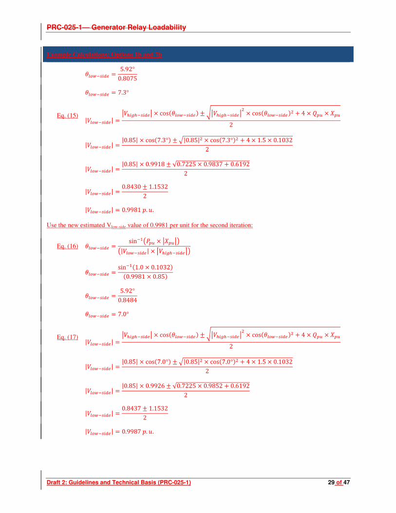
Eq. (15) |XY#*| \ *^Y#*\ 4 cos>NXY#*? ` a\ *^Y#*\< 4 cos>NXY#*?< 9 4 4 5$ 4 T$
2
|XY#*| |0.85| 4 cos>7.3°? ` b|0.85|< 4 cos>7.3°?< 9 4 4 1.5 4 0.10322
|XY#*| |0.85| 4 0.9918 ` √0.7225 4 0.9837 9 0.61922
|XY#*| 0.8430 ` 1.15322
|XY#*| 0.9981 . 6. Use the new estimated Vlow-side value of 0.9981 per unit for the second iteration:
Eq. (16) NXY#* sinYCM$ 4 \T$\RM|XY#*| 4 ] *^Y#*_R
NXY#* sinYC>1.0 4 0.1032?>0.9981 4 0.85?
NXY#* 5.92°0.8484
NXY#* 7.0°
Eq. (17) |XY#*| \ *^Y#*\ 4 cos>NXY#*? ` a\ *^Y#*\< 4 cos>NXY#*?< 9 4 4 5$ 4 T$
2
|XY#*| |0.85| 4 cos>7.0°? ` b|0.85|< 4 cos>7.0°?< 9 4 4 1.5 4 0.10322
|XY#*| |0.85| 4 0.9926 ` √0.7225 4 0.9852 9 0.61922
|XY#*| 0.8437 ` 1.15322
|XY#*| 0.9987 . 6.

PRC-025-1— Generator Relay Loadability
Draft 2: Guidelines and Technical Basis (PRC-025-1) 30 of 47
Example Calculations: Options 1b and 7b
To account for system high-side nominal voltage and the transformer tap ratio:
Eq. (18) S$# |XY#*| 4 4 ()*
S$# 0.9987 . 6. 4 345 4 7 22 346.5 8
S$# 21.88
Apparent power (S):
Eq. (19) ( 9 :5
( 767.6 ! 9 :1151.3 123
( 1383.7∠56.3° Primary Impedance (Zpri):
Eq. (20) "* <(=
"* >21.88 ?<1383.7∠@ 56.3°
"* 0.3458∠56.3° Ω
Secondary impedance (Zsec):
Eq. (21) "#0 "* 4 +,*,*
"#0 0.3458∠56.3° Ω4<ABBB
A<BBC
"#0 0.3458∠56.3° Ω4 25
"#0 8.6462∠56.3° Ω
To satisfy the 115% margin in the requirement in Options 1b and 7b:
Eq. (22) "DEF ** "#0115%
"DEF ** 8.6462∠56.3° Ω 1.15
"DEF ** 7.5185∠56.3° Ω

PRC-025-1— Generator Relay Loadability
Draft 2: Guidelines and Technical Basis (PRC-025-1) 31 of 47
Example Calculations: Options 1b and 7b
Assume a Mho distance impedance relay with a maximum torque angle (MTA) set at 85˚, and then the maximum allowable impedance reach is:
Eq. (23) "G H |"DEF **|cosMNOPQ @ N#* R
"G H 7.5185Ωcos>85.0˚@ 56.3°?
"G H 7.5185 Ω0.8771
"G H 8.5715∠85.0° Ω
Example Calculations: Option 1c
This option requires simulation. Refer to the Machine Data at the beginning of this section for inputs and the Guidelines and Technical Basis for other pertinent information.
Example Calculations: Option 2a
Option 2a represents the simplest calculation for synchronous generators applying a phase time overcurrent (51V-R) voltage restrained relay:
Real Power output (P):
Eq. (24) 4
903 4 0.85
767.6 !
Reactive Power output (Q):
Eq. (25) 5 150% 4
5 1.5 4 767.6 !
5 1151.3 123
Option 2a, Table 1 – Bus Voltage, calls for a 0.95 per unit of the high-side nominal voltage for the generator bus voltage (Vgen):
Eq. (26) 0.95 . 6. 4 4 ()*
0.95 4 345 4 7 22 346.5 8
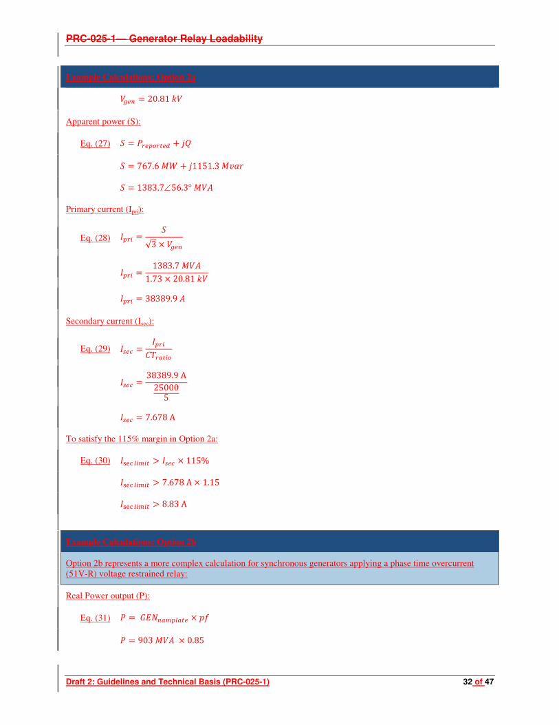
PRC-025-1— Generator Relay Loadability
Draft 2: Guidelines and Technical Basis (PRC-025-1) 32 of 47
Example Calculations: Option 2a
20.81
Apparent power (S):
Eq. (27) ( 9 :5
( 767.6 ! 9 :1151.3 123
( 1383.7∠56.3°
Primary current (Ipri):
Eq. (28) d* (√3 4
d* 1383.7 1.73 4 20.81
d* 38389.9
Secondary current (Isec):
Eq. (29) d#0 d*+,*
d#0 38389.9 A250005
d#0 7.678 A
To satisfy the 115% margin in Option 2a:
Eq. (30) dDEF ** f d#0 4 115%
dDEF ** f 7.678 A 4 1.15
dDEF ** f 8.83 A
Example Calculations: Option 2b
Option 2b represents a more complex calculation for synchronous generators applying a phase time overcurrent (51V-R) voltage restrained relay:
Real Power output (P):
Eq. (31) 4
903 4 0.85

PRC-025-1— Generator Relay Loadability
Draft 2: Guidelines and Technical Basis (PRC-025-1) 33 of 47
Example Calculations: Option 2b
767.6 !
Reactive Power output (Q):
Eq. (32) 5 150% 4
5 1.5 4 767.6 !
5 1151 123
Convert Real Power, Reactive Power, and transformer reactance to per unit values on 767.6 MVA base.
Real Power output (P):
Eq. (33) $ S#
$ 767.6 !767.6
$ 1.0 . 6. Reactive Power output (Q):
Eq. (34) 5$ 5S#
5$ 1151.3 123767.6
5$ 1.5 . 6. Transformer impedance:
Eq. (35) T$ TUVW>? 4 7S#UVW
8
T$ 12.14% 4 7767.6 903 8
T$ 0.1032 . 6. Use the formula below; calculate the low-side generator step-up transformer voltage (Vlow-side) using 0.85 p.u. high-side voltage (Vhigh-side). Estimate initial low-side voltage to be 0.95 p.u. Repeat the calculation if necessary until Vlow-
side converges:
Eq. (36) NXY#* sinYCM$ 4 \T$\RM|XY#*| 4 ] *^Y#*_R

PRC-025-1— Generator Relay Loadability
Draft 2: Guidelines and Technical Basis (PRC-025-1) 34 of 47
Example Calculations: Option 2b
NXY#* sinYC>1.0 4 0.1032?>0.95 4 0.85?
NXY#* 5.92°0.8075
NXY#* 7.3°
Eq. (37) |XY#*| \ *^Y#*\ 4 cos>NXY#*? ` a\ *^Y#*\< 4 cos>NXY#*?< 9 4 4 5$ 4 T$
2
|XY#*| |0.85| 4 cos>7.3°? ` b|0.85|< 4 cos>7.3°?< 9 4 4 1.5 4 0.10322
|XY#*| |0.85| 4 0.9918 ` √0.7225 4 0.9837 9 0.61922
|XY#*| 0.8430 ` 1.15322
|XY#*| 0.9981 . 6. Use the new estimated Vlow-side value of 0.9981 per unit for the second iteration:
Eq. (38) NXY#* sinYCM$ 4 \T$\RM|XY#*| 4 ] *^Y#*_R
NXY#* sinYC>1.0 4 0.1032?>0.9981 4 0.85?
NXY#* 5.92°0.8484
NXY#* 7.0°
Eq. (39) |XY#*| \ *^Y#*\ 4 cos>NXY#*? ` a\ *^Y#*\< 4 cos>NXY#*?< 9 4 4 5$ 4 T$
2
|XY#*| |0.85| 4 cos>7.0°? ` b|0.85|< 4 cos>7.0°?< 9 4 4 1.5 4 0.10322
|XY#*| |0.85| 4 0.9926 ` √0.7225 4 0.9852 9 0.61922
|XY#*| 0.8437 ` 1.15322
|XY#*| 0.9987 . 6.

PRC-025-1— Generator Relay Loadability
Draft 2: Guidelines and Technical Basis (PRC-025-1) 35 of 47
Example Calculations: Option 2b
To account for system high-side nominal voltage and the transformer tap ratio:
Eq. (40) S$# |XY#*| 4 4 ()*
S$# 0.9987 . 6. 4 345 4 7 22 346.5 8
S$# 21.88
Apparent power (S):
Eq. (41) ( 9 :5
( 767.6 ! 9 :1151.3 123
( 1383.7∠56.3° MVA
Primary current (Ipri):
Eq. (42) d* (√3 4 S$#
d* 1383.7 1.73 4 21.88
d* 36519.8
Secondary current (Isec):
Eq. (43) d#0 d*+,*
d#0 36519.8 A250005
d#0 7.304 A
To satisfy the 115% margin in Option 2b:
Eq. (44) dDEF ** f d#0 4 115%
dDEF ** f 7.304 A 4 1.15
dDEF ** f 8.4 A

PRC-025-1— Generator Relay Loadability
Draft 2: Guidelines and Technical Basis (PRC-025-1) 36 of 47
Example Calculations: Option 2c
This option requires simulation. Refer to the Machine Data at the beginning of this section for inputs and the Guidelines and Technical Basis for other pertinent information.
Example Calculations: Options 3 and 6
Option 3 represents the only calculation for synchronous generators applying a phase time overcurrent (51V-C) – voltage controlled relay (Enabled to operate as a function of voltage). Similarly, Option 6 uses the same calculation for asynchronous generators.
Real Power output (P):
Eq. (45) 4
903 4 0.85
767.6 !
Reactive Power output (Q):
Eq. (46) 5 150% 4
5 1.5 4 767.6 !
5 1151.3 123
Options 3 and 6, Table 1 – Bus Voltage, calls for a 1.0 per unit of the high-side nominal voltage for the generator bus voltage (Vgen):
Eq. (47) 1.0 . 6. 4 4 ()*
1.0 4 345 4 7 22 346.5 8
21.9
The voltage setting shall be set less than 75% of the generator bus voltage:
Eq. (48) #* H 4 75%
#* H 21.9 4 0.75
#* H 16.429

PRC-025-1— Generator Relay Loadability
Draft 2: Guidelines and Technical Basis (PRC-025-1) 37 of 47
Example Calculations: Options 4, 10, and 17
This represents the calculation for an asynchronous generator (including inverter-based installations) applying a phase distance (21) – directional toward the Transmission system relay. Similarly, these calculations may also be applied to other asynchronous applications, including Option 17 for generator step-up transformers and lines that radially connect a generating plant to the Transmission system. In this application it was assumed 100Mvar of static compensation was added.
Real Power output (P):
Eq. (49) 4
903 4 0.85
767.6 !
Reactive Power output (Q):
Eq. (50) 5 /#*0 9 4 sin>cosYC>?? 5 100 123 4 475.7 12
5 575.7 123
Options 4, 10, and 17, Table 1 – Bus Voltage, calls for a 1.0 per unit of the high-side nominal voltage for the generator bus voltage (Vgen):
Eq. (51) 1.0 . 6. 4 4 ()*
1.0 4 345 4 7 22 346.5 8
21.9
Apparent power (S):
Eq. (52) ( 9 :5
( 767.6 ! 9 :575.7 123
( 959.5∠36.9°
N#* 36.9° Primary impedance (Zpri):
Eq. (53) "* <(=
"* >21.9 ?<959.5∠ @ 36.9°
"* 0.5001∠36.9° Ω

PRC-025-1— Generator Relay Loadability
Draft 2: Guidelines and Technical Basis (PRC-025-1) 38 of 47
Example Calculations: Options 4, 10, and 17
Secondary impedance (Zsec):
Eq. (54) "#0 "* 4 +,*,*
"#0 0.5001∠36.9 Ω4<ABBB
A<BBC
"#0 0.5001∠36.9° Ω4 25
"#0 12.502∠36.9° Ω
To satisfy the 130% margin in Option 1a:
Eq. (55) "DEF ** "#0130%
"DEF ** 12.502∠36.9° Ω 1.30
"DEF ** 9.617∠36.9° Ω
Assume a Mho distance impedance relay with a maximum torque angle (MTA) set at 85˚, and then the maximum allowable impedance reach is:
Eq. (56) "G H |"DEF **|cosMNOPQ @ N#* R
"G H 9.617 Ωcos>85.0° @ 36.9°?
"G H 9.617 Ω0.6678
"G H 14.401∠85.0° Ω
Example Calculations: Option 5
This represents the calculation for asynchronous generators applying a phase time overcurrent (51V-R) – voltage restrained relay. In this application it was assumed 100Mvar of static compensation was added. Similarly, Option 6 uses the same calculation for asynchronous generators.
Real Power output (P):
Eq. (57) 4
903 4 0.85

PRC-025-1— Generator Relay Loadability
Draft 2: Guidelines and Technical Basis (PRC-025-1) 39 of 47
Example Calculations: Option 5
767.6 !
Reactive Power output (Q):
Eq. (58) 5 /#*0 9 4 sin>cosYC>?? 5 100 123 9 475.7 123
5 575.7 123
Option 5, Table 1 – Bus Voltage, calls for a 1.0 per unit of the high-side nominal voltage for the generator bus voltage (Vgen):
Eq. (59) 1.0 . 6. 4 4 ()*
1.0 4 345 4 7 22 346.5 8
21.9
Apparent power (S):
Eq. (60) ( 9 :5
( 767.6 ! 9 :575.7 123
( 959.5∠36.9°
Primary current (Ipri):
Eq. (61) d* (√3 4
d* 959.5 1.73 4 21.9
d* 25295.3
Secondary current (Isec):
Eq. (62) d#0 d*+,*
d#0 25295.3 A250005
d#0 5.06 A

PRC-025-1— Generator Relay Loadability
Draft 2: Guidelines and Technical Basis (PRC-025-1) 40 of 47
Example Calculations: Option 5
To satisfy the 130% margin in Option 5:
Eq. (63) dDEF ** f d#0 4 130%
dDEF ** f 5.06 A 4 1.30
dDEF ** f 6.58∠ @ 36.9°
Example Calculations: Option 8a, 8b, 9a, 9b, 15a, and 16a
Option 8a represents the calculation for a generator step-up (GSU) transformer applying a phase time overcurrent (51) relay connected to a synchronous generator. Similarly, these calculations can be applied to other synchronous generator applications, including Option 9a for generator step-up transformers applying a phase directional time overcurrent (67) directional toward the Transmission system relay, and Option 15a and 16a for lines that radially connect a generating plant to the Transmission system using a phase time overcurrent (51) and phase directional time overcurrent (67) directional toward the Transmission system relay, respectively. Options 8b and 9b use the same process, except the bus voltage is 0.85 per unit is used instead of 0.95 and excludes the generator step-up (GSU) impedance.
This example uses Option 8b as an example.
Real Power output (P):
Eq. (64) 4
903 4 0.85
767.6 !
Reactive Power output (Q):
Eq. (65) 5 150% 4
5 1.5 4 767.6 !
5 1151.3 123
Option 8b, Table 1 – Bus Voltage, calls for a 0.85 per unit of the high-side nominal voltage:
Eq. (66) S$# 0.85 . 6. 4
0.85 4 345
293.25
Apparent power (S):
Eq. (67) ( 9 :5

PRC-025-1— Generator Relay Loadability
Draft 2: Guidelines and Technical Basis (PRC-025-1) 41 of 47
Example Calculations: Option 8a, 8b, 9a, 9b, 15a, and 16a
( 767.6 ! 9 :1151.3 123
( 1383.7∠56.3°
Primary current (Ipri):
Eq. (68) d* (√3 4 S$#
d* 1383.7 1.73 4 293.25
d* 2724.3
Secondary current (Isec):
Eq. (69) d#0 d*+,*
d#0 2724.3 A250005
d#0 0.545 A
To satisfy the 115% margin in Option 8a:
Eq. (70) dDEF ** f d#0 4 115%
dDEF ** f 0.545 A 4 1.15
dDEF ** f 0.627 A
Example Calculations: Options 7c, 8c, 9c 14b, 15b, and 16b
These options require simulation. Refer to the Machine Data at the beginning of this section for inputs and the Guidelines and Technical Basis for other pertinent information.

PRC-025-1— Generator Relay Loadability
Draft 2: Guidelines and Technical Basis (PRC-025-1) 42 of 47
Example Calculations: Options 11a and 12
Option 11 represents the calculation for a generator step-up (GSU) transformer applying a phase time overcurrent (51) relay connected to an asynchronous generator. Similarly, these calculations can be applied to Option 12 for a phase directional time overcurrent (67) directional toward the Transmission system relay. In this application it was assumed 100Mvar of static compensation was added.
Real Power output (P):
Eq. (71) 4
903 4 0.85
767.6 !
Reactive Power output (Q):
Eq. (72) 5 /#*0 9 4 sin>cosYC>?? 5 100 123 9 475.7 123
5 575.7 123
Options 11 and 12, Table 1 – Bus Voltage, calls for a 1.0 per unit of the high-side nominal voltage for the generator bus voltage (Vgen):
Eq. (73) 1.0 . 6. 4 4 ()*
1.0 4 345 4 7 22 346.5 8
21.9
Apparent power (S):
Eq. (74) ( 9 :5
( 767.6 ! 9 :575.7 123
( 959.5∠36.9°
Primary current (Ipri):
Eq. (75) d* (√3 4
d* 959.5 1.73 4 21.9
d* 25295

PRC-025-1— Generator Relay Loadability
Draft 2: Guidelines and Technical Basis (PRC-025-1) 43 of 47
Example Calculations: Options 11a and 12
Secondary current (Isec):
Eq. (76) d#0 d*+,*
d#0 25295 A250005
d#0 5.059 A
To satisfy the 130% margin in Options 11 and12:
Eq. (77) dDEF ** f d#0 4 130%
dDEF ** f 5.059 A 4 1.30
dDEF ** f 6.575 A
Example Calculations: Option 13a and 13b
Option 13a of the unit auxiliary transformer (UAT) assumes that the maximum nameplate rating of the winding utilized for the purposes of the calculations and the appropriate voltage. Similarly, Option 13b uses the measured current while operating at the maximum gross MW capability reported to the Planning Coordinator or Transmission Planner.
Primary current (Ipri):
Eq. (78) d* ),√3 4 $
d* 60 1.73 4 13.8
d* 2510.2
Secondary current (Isec):
Eq. (79) d#0 d*+,$
d#0 2510.2 A50005
d#0 2.51 A

PRC-025-1— Generator Relay Loadability
Draft 2: Guidelines and Technical Basis (PRC-025-1) 44 of 47
Example Calculations: Option 13a and 13b
To satisfy the 150% margin in Option 13a:
Eq. (80) dDEF ** f d#0 4 150%
dDEF ** f 2.51 A 4 1.50
dDEF ** f 3.77 A
Example Calculations: Option 14a
Option 14a represents the calculation for lines that radially connect an asynchronous generating plant to the Transmission system for a phase directional time overcurrent (67) directional toward the Transmission system relay.
Real Power output (P):
Eq. (81) 4
903 4 0.85
767.6 !
Reactive Power output (Q):
Eq. (82) 5 150% 4
5 1.5 4 767.6 !
5 1151.3 123
Option 14a, Table 1 – Bus Voltage, calls for a 0.85 per unit of the high-side nominal voltage for the generator step-up (GSU) voltage (Vnom):
Eq. (83) S$# 0.85 . 6. 4
0.85 4 345
293.25
Apparent power (S):
Eq. (84) ( 9 :5
( 767.6 ! 9 :1151.3 123
( 1383.7∠56.3°
N#* 56.3°

PRC-025-1— Generator Relay Loadability
Draft 2: Guidelines and Technical Basis (PRC-025-1) 45 of 47
Example Calculations: Option 14a
Primary impedance (Zpri):
Eq. (85) "* S$#<(=
"* >293.25 ?<1383.7∠@ 56.3°
"* 62.1481∠56.3° Ω
Secondary impedance (Zsec):
Eq. (86) "#0 "* 4 +,*,*
"#0 62.1481∠56.3° Ω4<ABBB
A<BBC
"#0 62.1481∠56.3° Ω4 25
"#0 1553.7∠56.3° Ω
To satisfy the 115% margin in Option 14a:
Eq. (87) "DEF ** "#0115%
"DEF ** 1553.7∠56.3° Ω 1.15
"DEF ** 1351.0∠56.3° Ω
Assume a Mho distance impedance relay with a maximum torque angle (MTA) set at 85˚, and then the maximum allowable impedance reach is:
Eq. (88) "G H |"DEF **|cosMNOPQ @ N#* R
"G H 1351.0 Ωcos>85.0° @ 56.3°?
"G H 1651.0 Ω0.8771
"G H 1540.3∠85.0° Ω

PRC-025-1— Generator Relay Loadability
Draft 2: Guidelines and Technical Basis (PRC-025-1) 46 of 47
Example Calculations: Options 11b, 18, and 19
Option 11b represents the calculation for a generator step-up (GSU) transformer applying a phase time overcurrent (51) relay connected to an asynchronous generator. Similarly, Option 18 may also be applied here as well for generation interconnection Facilities and Option 19 for the phase directional time overcurrent (67) directional toward the Transmission system relays for generation interconnection Facilities. In this application it was assumed 100 Mvar of static compensation was added.
Real Power output (P):
Eq. (89) 4
903 4 0.85
767.6 !
Reactive Power output (Q):
Eq. (90) 5 /#*0 9 4 sin>cosYC>?? 5 100 123 9 475.7 123
5 575.7 123
Options 11b, 18, and 19, Table 1 – Bus Voltage, calls for a 1.0 per unit of the high-side nominal voltage for the generator bus voltage (Vgen):
Eq. (91) 1.0 . 6. 4
1.0 4 345
345
Apparent power (S):
Eq. (92) ( 9 :5
( 767.6 ! 9 :575.7 123
( 959.5∠36.9°
Primary current (Ipri):
Eq. (93) d* (√3 4
d* 959.5 1.73 4 345
d* 1605

PRC-025-1— Generator Relay Loadability
Draft 2: Guidelines and Technical Basis (PRC-025-1) 47 of 47
Example Calculations: Options 11b, 18, and 19
Secondary current (Isec):
Eq. (94) d#0 d*+,-.
d#0 1605 A20005
d#0 4.014 A
To satisfy the 130% margin in Options 11b, 18, and 19:
Eq. (95) dDEF ** f d#0 4 130%
dDEF ** f 4.014 A 4 1.30
dDEF ** f 5.218 A
End of calculations