guideline for european technical approval · guideline for european technical approval of ......
TRANSCRIPT
1/93
ETAG n°032Edition of May 2013
GUIDELINE FOR EUROPEAN TECHNICALAPPROVAL
of
EXPANSION JOINTS FOR ROAD BRIDGES
_____________________________________________
(Part one : G E N E R A L)
© EOTA 2013Kunstlaan 40 Avenue des Arts
B - 1040 BRUSSELS
European Organisation for Technical Approvals
Europäische Organisation für Technische Zulassungen
Organisation Européenne pour l’Agrément Technique
2/93
Table of ContentsFOREWORD......................................................................................................................................................... 6
SECTION ONE: INTRODUCTION ................................................................................................................ 10
1. PRELIMINARIES .................................................................................................................................... 101.1 Legal basis .............................................................................................................................................. 101.2 Status of ETAG........................................................................................................................................ 10
2. SCOPE .......................................................................................................................................................... 112.1 General ................................................................................................................................................... 11
2.1.1 Detailed scope .................................................................................................................................................... 112.1.2 Parts ................................................................................................................................................................... 11
2.1.2.1 General ....................................................................................................................................................... 112.1.2.2 Families of product ..................................................................................................................................... 12
2.1.3 Relationship with European harmonized standards ........................................................................................... 122.2. USE CATEGORIES AND KITS.............................................................................................................. 13
2.2.1 Use categories .................................................................................................................................................... 132.2.2 Kits..................................................................................................................................................................... 13
2.3 ASSUMPTIONS ...................................................................................................................................... 132.3.1 Main structure .................................................................................................................................................... 142.3.2 Temperatures...................................................................................................................................................... 142.3.3 Installation ......................................................................................................................................................... 142.3.4 Working life ....................................................................................................................................................... 14
3. TERMINOLOGY.......................................................................................................................................... 153.1 Common terminology and abbreviations ................................................................................................ 153.2 Terminology and abbreviations specific to this ETAG............................................................................ 15
3.2.1 Terminology....................................................................................................................................................... 153.2.2 Abbreviations..................................................................................................................................................... 19
SECTION TWO: GUIDANCE FOR THE ASSESSMENT OF THE FITNESS FOR USE........................ 20
GENERAL NOTES .......................................................................................................................................... 204. REQUIREMENTS........................................................................................................................................ 22
4.0 Table linking the Essential Requirements to Road Bridge Expansion Joint performance...................... 234.1 Kits .......................................................................................................................................................... 23
4.1.1 Mechanical resistance and stability .................................................................................................................... 234.1.1.1 General ....................................................................................................................................................... 234.1.1.2 Mechanical resistance ................................................................................................................................. 244.1.1.3 Resistance to fatigue ................................................................................................................................... 244.1.1.4 Seismic behaviour....................................................................................................................................... 244.1.1.5 Movement capacity..................................................................................................................................... 274.1.1.6 Cleanability................................................................................................................................................. 274.1.1.7 Resistance to wear ...................................................................................................................................... 274.1.1.8 Watertightness ............................................................................................................................................ 27
4.1.2 Safety in case of fire........................................................................................................................................... 274.1.3 Hygiene, health and environment....................................................................................................................... 27
4.1.3.1 Release of dangerous substances ................................................................................................................ 274.1.4 Safety in use ....................................................................................................................................................... 28
4.1.4.1 Ability to bridge gaps and levels in the running surface............................................................................. 284.1.4.2 Skid resistance ............................................................................................................................................ 304.1.4.3 Drainage capacity ....................................................................................................................................... 30
4.1.5 Protection against noise ..................................................................................................................................... 304.1.6 Energy economy and heat retention ................................................................................................................... 304.1.7 Aspects of durability, serviceability and identification of the products ............................................................. 30
4.1.7.1 Aspects of durability................................................................................................................................... 304.1.7.2 Aspects of serviceability ............................................................................................................................. 314.1.7.3 Aspects of identification ............................................................................................................................. 31
4.2 Components............................................................................................................................................. 325. METHODS OF VERIFICATION................................................................................................................. 33
5.0 General ................................................................................................................................................... 335.1 Kits .......................................................................................................................................................... 33
5.1.1 Mechanical resistance and stability .................................................................................................................... 335.1.1.1 General ....................................................................................................................................................... 33
3/93
5.1.1.2 Mechanical resistance ................................................................................................................................. 345.1.1.3 Resistance to fatigue ................................................................................................................................... 345.1.1.4 Seismic behaviour....................................................................................................................................... 355.1.1.5 Movement capacity..................................................................................................................................... 355.1.1.6 Cleanability................................................................................................................................................. 355.1.1.7 Resistance to wear ...................................................................................................................................... 365.1.1.8 Watertightness ............................................................................................................................................ 36
5.1.2 Safety in case of fire........................................................................................................................................... 365.1.3 Hygiene, health and environment....................................................................................................................... 36
5.1.3.1 Presence of dangerous substances in the product ....................................................................................... 365.1.3.2 Compliance with the applicable regulations ............................................................................................... 365.1.3.3 Application of the precautionary principle ................................................................................................. 36
5.1.4 Safety in use ....................................................................................................................................................... 375.1.4.1 Ability to bridge gaps and levels in the running surface............................................................................. 375.1.4.2 Skid resistance ............................................................................................................................................ 375.1.4.3 Drainage capacity ....................................................................................................................................... 37
5.1.5 Protection against noise ..................................................................................................................................... 375.1.6 Energy economy and heat retention ................................................................................................................... 375.1.7 Aspects of durability, serviceability and identification of the products ............................................................. 37
5.1.7.1 Aspects of durability................................................................................................................................... 375.1.7.2 Aspects of serviceability ............................................................................................................................. 395.1.7.3 Aspects of identification ............................................................................................................................. 39
5.2 Components............................................................................................................................................. 396. ASSESSING AND JUDGING THE FITNESS OF PRODUCTS FOR AN INTENDED USE..................... 40
6.0 Table linking the Essential Requirements to product requirements........................................................ 406.1 Kits .......................................................................................................................................................... 41
6.1.1 Mechanical resistance and stability.................................................................................................................... 416.1.1.1 General ....................................................................................................................................................... 416.1.1.2 Mechanical resistance ................................................................................................................................. 416.1.1.3 Resistance to fatigue ................................................................................................................................... 416.1.1.4 Seismic behaviour....................................................................................................................................... 416.1.1.5 Movement capacity..................................................................................................................................... 416.1.1.6 Cleanability................................................................................................................................................. 416.1.1.7 Resistance to wear ...................................................................................................................................... 416.1.1.8 Watertightness ............................................................................................................................................ 41
6.1.2 Safety in case of fire........................................................................................................................................... 426.1.3 Hygiene, health and environment (ER 3) ........................................................................................................... 42
6.1.3.1 Release of dangerous substances ................................................................................................................ 426.1.4 Safety in use ....................................................................................................................................................... 42
6.1.4.1 Ability to bridge gaps and levels in the running surface............................................................................. 426.1.4.2 Skid resistance ............................................................................................................................................ 426.1.4.3 Drainage capacity ....................................................................................................................................... 42
6.1.5 Protection against noise ..................................................................................................................................... 426.1.6 Energy economy and heat retention ................................................................................................................... 426.1.7 Aspects of durability, serviceability and identification of the products ............................................................. 43
6.1.7.1 Aspects of durability................................................................................................................................... 436.1.7.2 Aspects of serviceability ............................................................................................................................. 446.1.7.3 Aspects of identification ............................................................................................................................. 44
6.2 Components............................................................................................................................................. 447. ASSUMPTIONS AND RECOMMENDATIONS UNDER WHICH THE FITNESS FOR USE OF THEPRODUCTS IS ASSESSED ............................................................................................................................. 45
7.0 General ................................................................................................................................................... 457.1 Design of works....................................................................................................................................... 457.2 Packaging, transport and storage........................................................................................................... 46
7.2.1 Packaging........................................................................................................................................................... 467.2.2 Transport and storage......................................................................................................................................... 46
7.3 Execution of works .................................................................................................................................. 467.4. Maintenance and repair......................................................................................................................... 47
SECTION THREE: ATTESTATION OF CONFORMITY (AOC) .............................................................. 48
8. ATTESTATION AND EVALUATION OF CONFORMITY ...................................................................... 488.1 EC decision ............................................................................................................................................. 488.2 Responsibilities ....................................................................................................................................... 48
8.2.1 Tasks for the manufacturer................................................................................................................................. 488.2.1.1 Factory production control (FPC)............................................................................................................... 488.2.1.2 Testing of samples taken at the factory – Prescribed Test Plan .................................................................. 50
4/93
8.2.2 Tasks of the Approved Body.............................................................................................................................. 508.2.2.1 General ....................................................................................................................................................... 508.2.2.2 Initial Type-Testing .................................................................................................................................... 508.2.2.3 Assessment of the factory production control system. Initial inspection and continuous surveillance ....... 508.2.2.4 Certification ................................................................................................................................................ 50
8.3 Documentation ........................................................................................................................................ 518.4 CE marking and accompanying information .......................................................................................... 52
SECTION FOUR: ETA CONTENT ................................................................................................................. 53
9. THE ETA CONTENT................................................................................................................................... 539.1 The ETA-content ..................................................................................................................................... 53
9.1.1 Model ETA ........................................................................................................................................................ 539.1.2 Checklist for the Approval Body........................................................................................................................ 53
9.2 Additional information............................................................................................................................ 569.3 Confidential information......................................................................................................................... 579.4 Installation requirements ........................................................................................................................ 57
ANNEXES TO THE ETAG ............................................................................................................................... 58
ANNEX A COMMON TERMINOLOGY (DEFINITIONS, CLARIFICATIONS, ABBREVIATIONS) .. 59
ANNEX B ASSUMPTION OF WORKING LIFE OF CONSTRUCTION PRODUCTS (EOTAGUIDANCE DOCUMENT 002) ........................................................................................................................ 59
ANNEX C ASSESSMENT OF THE WORKING LIFE OF PRODUCTS (EOTA GUIDANCEDOCUMENT 003)............................................................................................................................................... 59
ANNEX D THE PROVISION OF DATA FOR ASSESSMENT LEADING TO ETA (EOTA GUIDANCEDOCUMENT 004)............................................................................................................................................... 59
ANNEX E EDITORIAL ASPECTS OF ETAGS (EOTA GUIDANCE DOCUMENT 005)......................... 59
ANNEX F REFERENCE MATERIAL FOR ETAGS, COMPREHENSION DOCUMENTS FOR ETAGS,UPDATING PROCESS OF ETAGS ................................................................................................................. 59
ANNEX G TRAFFIC LOADS AND COMBINATIONS................................................................................. 60
G.1 – GENERAL ................................................................................................................................................ 60G.2 – STATIC LOAD MODELS......................................................................................................................... 62
G.2.1 – Vertical load model .......................................................................................................................... 62G.2.1.1 – Tandem arrangements ................................................................................................................................. 62G.2.1.2 – Load Model 1 .............................................................................................................................................. 64G.2.1.3 – Loads on footways....................................................................................................................................... 67G.2.1.4 – Accidental load............................................................................................................................................ 67
G.2.2 – Horizontal load model...................................................................................................................... 68G.2.2.1 – Braking and acceleration forces .................................................................................................................. 68G.2.2.2 – Centrifugal forces ........................................................................................................................................ 69G.2.2.3 – Accidental loads .......................................................................................................................................... 69
G.2.2.3.1 – Kerb units not repairable and/or not replaceable ................................................................................. 69G.2.2.3.2 – Kerb units repairable and/or replaceable.............................................................................................. 70
G.3 – FATIGUE LOAD MODELS ....................................................................................................................... 70G.3.1 – General............................................................................................................................................. 70G.3.2 – Fatigue load Model 1 (FLM1EJ)....................................................................................................... 71G.3.3 – Fatigue Load Model 2 (FLM2EJ)...................................................................................................... 72
G.4 – VERIFICATION ........................................................................................................................................ 72G.4.1 – General............................................................................................................................................. 72G.4.2 – Combinations at the ultimate limit state........................................................................................... 72
G.4.2.1 – Traffic loads and design situations (combinations) ..................................................................................... 73G.4.2.2 – Combinations for accidental situations ....................................................................................................... 75G.4.2.3 – Combination for seismic design situations .................................................................................................. 75G.4.2.4 – Combination for fatigue limit state.............................................................................................................. 77
G.4.3 – Combinations at the serviceability limit state .................................................................................. 77G.4.3.1 – Characteristic combination.......................................................................................................................... 77G.4.3.2 – Frequent combination.................................................................................................................................. 78
5/93
List of abbreviations...................................................................................................................................... 79
ANNEX H NUMBER OF PRODUCTS TO BE TESTED............................................................................... 81
ANNEX J SEISMIC APPROACH DESIGN PHILOSOPHY FOR RBEJ .................................................... 83
J.1 – Introduction.......................................................................................................................................... 83J.2 – Movement capacity cases ..................................................................................................................... 83J.3 – Bridges with fusible links...................................................................................................................... 84
ANNEX K MOVEMENT CAPACITY TEST METHOD............................................................................... 85
K.1 – OBJECT ................................................................................................................................................... 85K.2 – SCOPE ..................................................................................................................................................... 85K.3 – TERMS AND DEFINITIONS ..................................................................................................................... 85
K.3.1 – Movement ......................................................................................................................................... 85K.3.2 – Movement capacity........................................................................................................................... 85K.3.3 – Horizontal displacement................................................................................................................... 85K.3.4 – Vertical displacement ....................................................................................................................... 85K.3.5 – Transverse displacement .................................................................................................................. 85K.3.6 – Gap ................................................................................................................................................... 86
K.4 – PRINCIPLE .............................................................................................................................................. 86K.5 – EQUIPMENT ............................................................................................................................................ 86K.6 – SAMPLES AND PREPARATION OF TEST SPECIMENS .................................................................. 87
K.6.1 – Dimensions ....................................................................................................................................... 87K.6.2 – Control of samples............................................................................................................................ 88K.6.3 – Installation of samples on the test frame .......................................................................................... 88
K.7 – PROCEDURE ........................................................................................................................................... 88K.7.1 – Testing conditions............................................................................................................................. 88K.7.2 – Test procedure .................................................................................................................................. 88
K.8 – EXPRESSION OF RESULTS ..................................................................................................................... 89K.9 – TEST REPORT ......................................................................................................................................... 89
ANNEX L WATERTIGHTNESS TEST METHOD........................................................................................ 90
L.1 – SCOPE ...................................................................................................................................................... 90L.2 – DEFINITIONS......................................................................................................................................... 90L.3 – PRINCIPLE ............................................................................................................................................. 90L.4 – SAMPLES AND PREPARATION OF TEST SPECIMENS................................................................... 92
L.4.1 – Dimensions........................................................................................................................................ 92L.4.2 – Control of samples ............................................................................................................................ 92L.4.3 – Installation of samples on the test frame........................................................................................... 92L.4.4 – Test rig .............................................................................................................................................. 92
L.5 – TEST PROCEDURE................................................................................................................................ 92L.5.1 – Beginning of the test ......................................................................................................................... 92L.5.2 – Test temperature ............................................................................................................................... 92L.5.3 – Execution of the test .......................................................................................................................... 92
L.6 – EXPRESSION OF THE RESULTS......................................................................................................... 93L.7 – TEST REPORT........................................................................................................................................ 93

6/93
FOREWORD
- Background of the subject
This draft ETA Guideline has been established by WG 01.07/02 “Expansion joints” dealing withexpansion joints used on road bridges. The Working Group consisted of members from 8 EU-countries; Austria, Belgium, Czech Republic, Finland, France (convenorship), Germany, Italy,Netherlands and United Kingdom. In addition, Switzerland and Slovenia have been correspondingmembers together with members appointed by the European Expansion Joint ManufacturersAssociation.
Since Expansion joints are based on different functioning principles and materials, which mightnecessitate additional specific verification and /or assessment, they’ve been divided into the followingproduct families:
Buried expansion jointFlexible plug expansion joint
Note: Which is a flexible expansion joint in the sense of the mandate.Nosing expansion jointMat expansion jointCantilever expansion jointSupported expansion jointModular expansion joint
This ETA Guideline Part 1 – General deals with common aspects and shall be used in conjunction withone of the relevant complementary part for each product (see 2.1.2).
- Reference documents
Reference documents are referred to within the body of the ETAG and are subject to the specificconditions mentioned therein.
The list of reference documents (mentioning the year of issue, where relevant) for this ETAG isgiven below. Additional parts of this ETAG modify this list to be applicable to that Part.
Updating conditions
The edition of a reference document given in this list is that which has been adopted by EOTA for itsspecific use.
When a new edition becomes available, this supersedes the edition mentioned in the list only whenEOTA has verified or re-established (possibly with appropriate linkage) its compatibility with theGuideline.
EOTA Technical Reports go into detail in some aspects and as such are not part of the ETAG butexpress the common understanding of existing knowledge and experience of the EOTA-bodies at thatmoment. When knowledge and experience is developing, especially through approval work, thesereports can be amended and supplemented.
EOTA Comprehension Documents permanently take on board all useful information on the generalunderstanding of this ETAG as developed when delivering ETAs by consensus among the EOTAmembers. Readers and users of this ETAG are advised to check the current status of thesedocuments with an EOTA member.
EOTA may need to make alterations/corrections to the ETAG during its life. These changes will beincorporated into the official version on the EOTA website www.eota.be and the actions cataloguedand dated in the associated Progress File.

7/93
Readers and users of this ETAG are advised to check the current status of the content of thisdocument with that on the EOTA website. The front cover will indicate if and when amendment hastaken place.
-----------------------EC/EOTA documents
[1] CPD: Directive relating to construction products. Council Directive of 21 December1988 on the approximation of laws, regulations and administrative provisions of theMember States relating to construction products (89/106/EEC) taking account of themodified provisions (93/68/EEC).
[2] ID No 1 (Mechanical Resistance and Stability): Council Directive 89/106/EEC,Construction Products Interpretative Documents.
[3] ID No 3 (Hygiene, Health and the Environment): Council Directive 89/106/EEC,Construction Products Interpretative Documents.
[4] ID No 4 (Safety in use): Council Directive 89/106/EEC, Construction ProductsInterpretative Documents.
[5] ID No 5 (Protection against noise): Council Directive 89/106/EEC, ConstructionProducts Interpretative Documents.
[6] EC Guidance Paper A: The designation of Approved Bodies in the field of theconstruction products directive, CONSTRUCT 95/149 Rev. 2.
[7] EC Guidance Paper B: The definition of factory production control in technicalspecifications for construction products, CONSTRUCT 95/135 Rev 1.
[8] EC Guidance Paper C: The treatment of kits and systems under the constructionproducts directive, CONSTRUCT 96/175 Rev. 2.
[9] EC Guidance Paper D: CE-marking under the construction products directive,CONSTRUCT 97/220 Rev. 5.
[10] EC Guidance Paper E: Levels and classes in the Construction Product Directive,CONSTRUCT 99-337 Rev.1.
[11] EC Guidance Paper F: Durability and the Construction Products Directive,CONSTRUCT 99/367.
[12] EC Guidance Paper H: A harmonised approach relating to dangerous substancesunder the Construction Product Directive, CONSTRUCT 99/363 Rev.1.
[13] EC Guidance Paper L: Application and use of Eurocodes under the ConstructionProduct Directive, CONSTRUCT 01/483 Rev.1.
[14] ETA-format: Commission decision of 22nd July 1997 on the general format ofEuropean Technical Approvals for construction products, 97/571/EC, O.J. No L 236/7 to13, 27th August 1997.
[15] The provision of data for assessments leading to ETA, 31st EOTA Technical Board,20-21 January 1999.

8/93
European Standards:
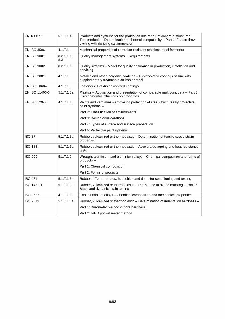
LIST OF STANDARDS REFERRED TO IN THIS ETAG (ROAD BRIDGE EXPANSION JOINTS)
Standards Clause ofthis ETAG Title
EN 573 5.1.7.1.1 Aluminium and aluminium alloys – Chemical composition and form of wroughtproducts –
Part 1: Numerical designation system
Part 2: Chemical symbol based designation system
Part 3: Chemical composition
Part 4: Form of products
EN 1504-2 5.1.7.1.4 Products and systems for the protection and repair of concrete structure –Definition, requirements, quality control and evaluation of conformity – Part 2:Surface protection systems for concrete
EN 1706 5.1.7.1.1 Aluminium and aluminium alloys – Castings – Chemical composition andmechanical properties
EN 1990 (2003) 4.1.1.4,5.1.1.2.1,5.1.1.2.2,5.1.1.3.1,J.2
Eurocode – Basis of structural design
EN 1991-1-5 2.3.2 Eurocode 1: Actions on structures – Part 1-5: General actions – Thermalactions
EN 1991-2 (2004) 2.3.4, 3.2.1,7.1, G1,G.2.1,G.2.1.4,G.2.2,G.2.2.3,G.3.1,G.3.3,Table G.6
Eurocode 1: Actions on structures – Part 2: Traffic loads on bridges
EN 1993-1-9 5.1.1.3.1 Eurocode 3: Design of steel structures – Fatigue strength of steel structures
EN 1993-2 5.1.1.3.1 Eurocode 3: Design of steel structures – Steel bridges
EN 1998-2 5.1.1.4, J1 Eurocode 8: Design of structures for earthquake resistance – Part 2: Bridges
EN 10088 4.1.7.1.1 Stainless steels –
Part 1: List of stainless steels
Part 2: Technical delivery conditions for sheet/plate and strip for generalpurposes
Part 3: Technical delivery conditions for semi-finished products, bars, rods,and sections for general purposes
Part 4: Technical delivery conditions for sheet/plate and strip of corrosionresisting steels for construction purposes (prEN)
Part 5: Technical delivery conditions for bars, rods, wire, sections and brightproducts of corrosion resisting steels for construction purposes (prEN)
EN 10204 8.2.1.1.2 Metallic products – Types of inspection documents
EN 13036-4 5.1.4.2 Road and airfield surface characteristics – Test methods – Part 4: Method formeasurement of slip/skid resistance of a surface – The pendulum test
9/93
EN 13687-1 5.1.7.1.4 Products and systems for the protection and repair of concrete structures –Test methods – Determination of thermal compatibility – Part 1: Freeze-thawcycling with de-icing salt immersion
EN ISO 3506 4.1.7.1 Mechanical properties of corrosion-resistant stainless-steel fasteners
EN ISO 9001 8.2.1.1.1,8.3
Quality management systems – Requirements
EN ISO 9002 8.2.1.1.1 Quality systems – Model for quality assurance in production, installation andservicing
EN ISO 2081 4.1.7.1 Metallic and other inorganic coatings – Electroplated coatings of zinc withsupplementary treatments on iron or steel
EN ISO 10684 4.1.7.1 Fasteners. Hot dip galvanized coatings
EN ISO 11403-3 5.1.7.1.3a Plastics – Acquisition and presentation of comparable multipoint data – Part 3:Environmental influences on properties
EN ISO 12944 4.1.7.1.1 Paints and varnishes – Corrosion protection of steel structures by protectivepaint systems –
Part 2: Classification of environments
Part 3: Design considerations
Part 4: Types of surface and surface preparation
Part 5: Protective paint systems
ISO 37 5.1.7.1.3a Rubber, vulcanized or thermoplastic – Determination of tensile stress-strainproperties
ISO 188 5.1.7.1.3a Rubber, vulcanized or thermoplastic – Accelerated ageing and heat resistancetests
ISO 209 5.1.7.1.1 Wrought aluminium and aluminium alloys – Chemical composition and forms ofproducts –
Part 1: Chemical composition
Part 2: Forms of products
ISO 471 5.1.7.1.3a Rubber – Temperatures, humidities and times for conditioning and testing
ISO 1431-1 5.1.7.1.3c Rubber, vulcanized or thermoplastic – Resistance to ozone cracking – Part 1:Static and dynamic strain testing
ISO 3522 4.1.7.1.1 Cast aluminium alloys – Chemical composition and mechanical properties
ISO 7619 5.1.7.1.3a Rubber, vulcanized or thermoplastic – Determination of indentation hardness –
Part 1: Durometer method (Shore hardness)
Part 2: IRHD pocket meter method
10/93
Section one:INTRODUCTION
1. PRELIMINARIES
1.1 LEGAL BASIS
This ETAG has been established in compliance with the provisions of the Council Directive89/106/EEC (CPD) taking into account the following steps:
- the final mandate issued by the EC : 02/10/2000 as laid down inCONSTRUCT 00/409 revised, amended at 30/11/2005 as laid down in CONSTRUCT 05/718
- the final mandate issued by the EFTA : IDEM
- adoption of the Guideline by the Executive Commission of EOTA :
- opinion of the Standing Committee for Construction :
- endorsement by the EC :
This document is published by the Member States in their official language or languages according toArticle 11.3 of the CPD.
For the first one, mention "No existing ETAG is superseded".
1.2 STATUS OF ETAG
a. An ETA is one of the two types of technical specifications in the sense of the EC 89/106Construction Products Directive. This means that Member States shall presume that the approvedRoad Bridge Expansion Joints are fit for their intended use, i.e. they enable works in which they areemployed to satisfy the Essential Requirements during an economically reasonable working life,provided that:
- the works are properly designed and built,- the conformity of the products with the ETA has been properly attested.
b. This ETAG is a basis for ETAs, i.e. a basis for technical assessment of the fitness for use of aRoad Bridge Expansion Joint for an intended use. An ETAG is not itself a technical specification in thesense of the CPD.
This ETAG expresses the common understanding of the Approval Bodies, acting together withinEOTA, as to the provisions of the Construction Products Directive 89/106 and of the InterpretativeDocuments, in relation to the expansion joint and uses concerned, and is written within the frameworkof a mandate given by the Commission and the EFTA Secretariat, after consulting the StandingCommittee for Construction.
c. When accepted by the European Commission after consultation with the Standing Committee forConstruction this ETAG is binding for the issuing of ETAs for the Road Bridge Expansion Joint for thedefined intended uses.
The application and satisfaction of the provisions of an ETAG (examinations, tests and evaluationmethods) leads to an ETA and a presumption of fitness of a Road Bridge Expansion Joint for thedefined use only through an evaluation and approval process and decision, followed by thecorresponding attestation of conformity. This distinguishes an ETAG from a harmonised Europeanstandard, which is the direct basis for attestation of conformity.

11/93
Where appropriate, Road Bridge Expansion Joints, which are outside of the precise scope of thisETAG, may be considered through the approval procedure without Guidelines according to Article 9.2of the CPD.
The requirements in this ETAG are set out in terms of objectives and of relevant actions to be takeninto account. It specifies values and characteristics, the conformity with which gives the presumptionthat the requirements set out are satisfied, wherever the state of the art permits and after having beenconfirmed as appropriate for the particular product by the ETA.
2. SCOPE
2.1 GENERAL
2.1.1 Detailed scope
This ETAG specifies the product performance characteristics, methods of verification and assessmentprocedures for road bridge expansion joints to ensure the products for intended use.
This Guideline concerns the expansion joints for road bridges used to ensure the continuity of therunning surface as well as bearing capacity and the movement of the bridges whatever the nature ofthe structure constitutive material (concrete, steel, ...).
The products are designed, manufactured and installed in accordance with the ETA holder’s conceptand installation guide.
Expansion joints for moveable bridges are not covered by this Guideline.
2.1.2 Parts
2.1.2.1 General
This Guideline includes the following parts:
Part 1 - General, which is common to all families of products, shall be used in conjunction with thecomplementary family relevant Part.
Part 2 to 8 concerning each product family (specified according to their principle of operating) asfollow:
Families of expansion joints
Ref. to parts
Buried expansion joints 2
Flexible plug expansion joints 3
Nosing expansion joints 4
Mat expansion joints 5
Cantilever expansion joints 6
Supported expansion joints 7
Modular expansion joints 8
According to the Annex 1 of the mandate, other product families will be specified if relevant.
12/93
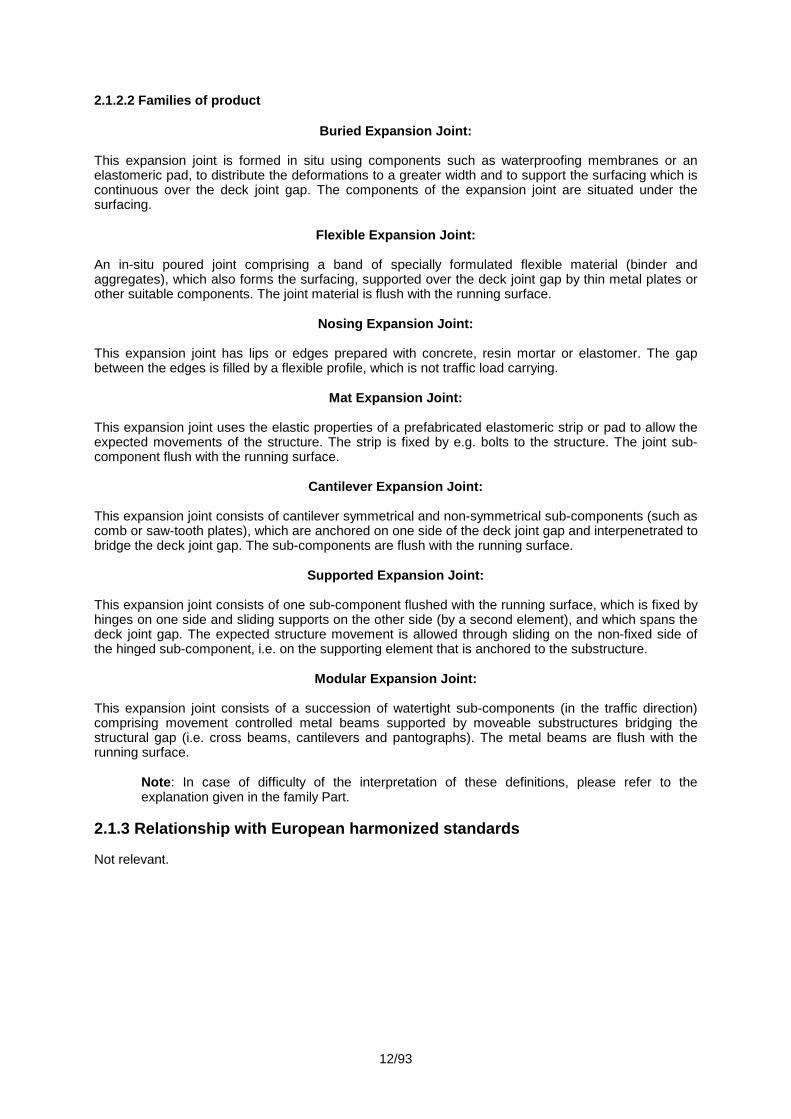
2.1.2.2 Families of product
Buried Expansion Joint:
This expansion joint is formed in situ using components such as waterproofing membranes or anelastomeric pad, to distribute the deformations to a greater width and to support the surfacing which iscontinuous over the deck joint gap. The components of the expansion joint are situated under thesurfacing.
Flexible Expansion Joint:
An in-situ poured joint comprising a band of specially formulated flexible material (binder andaggregates), which also forms the surfacing, supported over the deck joint gap by thin metal plates orother suitable components. The joint material is flush with the running surface.
Nosing Expansion Joint:
This expansion joint has lips or edges prepared with concrete, resin mortar or elastomer. The gapbetween the edges is filled by a flexible profile, which is not traffic load carrying.
Mat Expansion Joint:
This expansion joint uses the elastic properties of a prefabricated elastomeric strip or pad to allow theexpected movements of the structure. The strip is fixed by e.g. bolts to the structure. The joint sub-component flush with the running surface.
Cantilever Expansion Joint:
This expansion joint consists of cantilever symmetrical and non-symmetrical sub-components (such ascomb or saw-tooth plates), which are anchored on one side of the deck joint gap and interpenetrated tobridge the deck joint gap. The sub-components are flush with the running surface.
Supported Expansion Joint:
This expansion joint consists of one sub-component flushed with the running surface, which is fixed byhinges on one side and sliding supports on the other side (by a second element), and which spans thedeck joint gap. The expected structure movement is allowed through sliding on the non-fixed side ofthe hinged sub-component, i.e. on the supporting element that is anchored to the substructure.
Modular Expansion Joint:
This expansion joint consists of a succession of watertight sub-components (in the traffic direction)comprising movement controlled metal beams supported by moveable substructures bridging thestructural gap (i.e. cross beams, cantilevers and pantographs). The metal beams are flush with therunning surface.
Note: In case of difficulty of the interpretation of these definitions, please refer to theexplanation given in the family Part.
2.1.3 Relationship with European harmonized standards
Not relevant.
13/93
2.2. USE CATEGORIES AND KITS
2.2.1 Use categories
The use categories are specified with regard to the users and structure considerations. The ETA isgranted for combination(s) of categories described as follow:
User categories:- Vehicle,- Cyclist,- Pedestrian.
Actions categories:- Standard action (See § 4),- Optional action (accidental effects of heavy wheel on footpath, seismic phenomena; wheel
shock on the upstand, …).
2.2.2 Kits
The expansion joint is a "kit" ( as defined by EC GP C) composed of a set of at least two separatecomponents that need to be put together to be installed permanently in the works (i.e. to become an"assembled system").
The manufacturer is responsible for all components which are part of the kit.
The kit may be supplied in two ways:
- the manufacturer supplies all components required for the installed expansion joint,- the manufacturer supplies some of the components and specifies the others required for the
installed expansion joint.
In either case the manufacturer shall specify all components for which he takes the responsibility andthese shall be accessed by the Approval Body.
The manufacturer shall specify which parts of the expansion joint are replaceable (see 3.2.1"Replaceability").
Special accessories to facilitate installation (i.e. special product for temporary obtrusion of the gap inthe Flexible Expansion Joint) and butt joints are a part of the "kit".
Optional devices (e.g. special adaptation for cyclists or pedestrian), shall be addressed in the ETA.In its longitudinal axis, the joint may include one or more of the following sub-assemblies:
- Expansion joint for carriageway, with or without upstand,- Expansion joint for footpath, with or without upstand,- Upstand of expansion joint, as a separate sub-assembly.
Each sub-assembly may be made of different design according to different family Part.
Where an expansion joint is not entirely covered by just one family Part, that joint shall be assessedaccording to the family Parts which are applicable.
2.3 ASSUMPTIONS
The state of the art does not permit the development, within a reasonable time, of full and detailedverification methods and corresponding technical criteria/guidance for acceptance for some particularaspects or products. This ETAG contains assumptions taking account of the state of the art andmakes provisions for appropriate, additional case-by-case approaches when examining ETA-applications, within the general framework of the ETAG and under the CPD consensus procedurebetween EOTA members.
14/93
The guidance remains valid for other cases which do not deviate significantly. The general approach ofthe ETAG remains valid but the provisions then need to be used case by case in an appropriate way.This use of the ETAG is the responsibility of the Approval Body which receives the special application,and subject to consensus within EOTA. Experience in this respect is collected, after endorsement inEOTA-TB, in the ETAG-Format-Comprehension document.
2.3.1 Main structure
This ETAG gives recommendations for requirements concerning adequate support and method offixing the joints to the main structure.
2.3.2 Temperatures
The following levels of minimum and maximum operating temperatures shall be considered:
- Levels of minimum operating temperatures: -10, -20, -30, -40 °C,
- Levels of maximum operating temperatures: 35, 45 °C.
Surface areas, directly exposed to the sun, have to be assessed for the maximum operatingtemperature increased by 15 °K.
Note: In the meaning of this ETAG, the operating temperature is assumed to be the shade airtemperature according to EN 1991-1-5.
If relevant, more details on the influence of the temperature are given in the family Parts.
With respect to the required temperatures in the Member State where the expansion joint shall beused, a combination of specified levels of the minimum and maximum operating temperatures shall bechosen by the manufacturer as an operating temperature range.
2.3.3 Installation
Installation aspects, which are necessary to ensure fitness for use, are covered in Chapter 7.
2.3.4 Working life
The working life aspect is determined in conformity with "Guidance Paper F: Durability and theconstruction products directive" by using performance-based methods and/or descriptive solutions.
Concerning expansion joints the working life depends in particular on the external loads or the imposedmovements, the cycle frequency, the number of cycles and the durability (including fatigue, wearresistance …) of the expansion joint and its components. It is also linked with the ability to replacecomponents and the installation quality.
Therefore in relation to the assessments given in this ETAG the manufacturer shall declare theassumed working life of the kit (including its components). The assumed working life of the kit is basedon the following Working Life categories, with Nobs = 0,5 million/year (see EN 1991-2, Table 4.5 andAnnex G, G3.1):
Working Life category Years
1 10
2 15
3 25
4 50
The assumed working life of replaceable components shall be declared in the ETA.
15/93
In the family Parts, details are given about how the working life is assessed.
If, in exceptional and justified cases, a working life of less than 10 years for replaceable components isintroduced in a family Part, this shall be stated in the ETA.
3. TERMINOLOGY
3.1 COMMON TERMINOLOGY AND ABBREVIATIONS
See Annex A.
3.2 TERMINOLOGY AND ABBREVIATIONS SPECIFIC TO THIS ETAG
3.2.1 Terminology
AAccelerated ageing Procedure which simulates the ageing effects within a short period
Ageing Change of material properties under the influence of environmental conditionse.g. water, nitrogen, oxygen, salt (see also Guidance Paper F)
Anchorage system Bars and rods that connect the expansion joint to the main structure or theabutment
Asphaltic plugexpansion joint
See "flexible plug expansion joint"
Axle load The load applied on the pavement by one axle
BBatch Quantity of product or components manufactured to the same specification
within a determined period
Bellow An elastic sub-component which closes a gap and ensures watertightnessunder gap dimensions of a designed range
Buried expansion joint See definition given in Part 2
CCantilever ExpansionJoint
See definition given in Part 6
Crossing angle The angle between the longitudinal axis of the superstructure and the river,canal, road or valley whatever it bridges
DDowel Connecting steel sub-component welded to steel parts which transmits the
loads between steel parts and concrete structures
Drain A tube which collects and transports water (not necessarily only inside thebituminous concrete)
Drainage A system of drains and other devices, which transports water from the bridgesurface
16/93
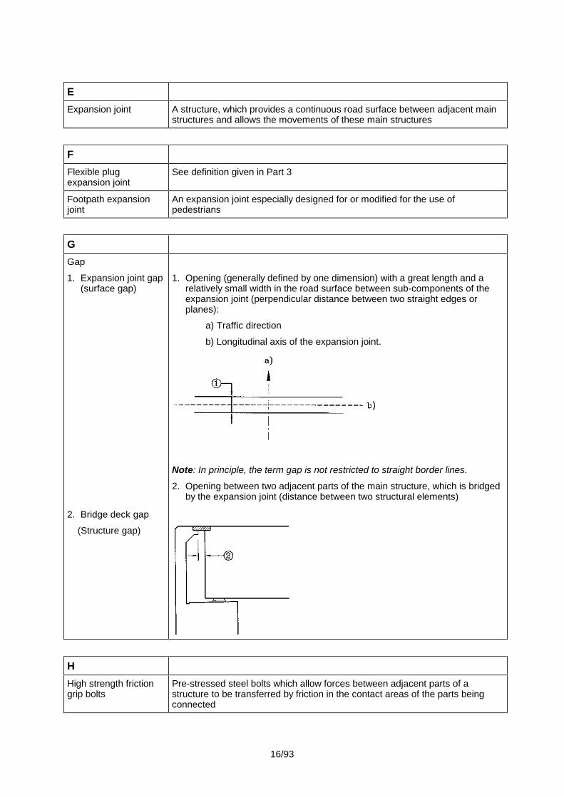
EExpansion joint A structure, which provides a continuous road surface between adjacent main
structures and allows the movements of these main structures
FFlexible plugexpansion joint
See definition given in Part 3
Footpath expansionjoint
An expansion joint especially designed for or modified for the use ofpedestrians
GGap
1. Expansion joint gap(surface gap)
2. Bridge deck gap
(Structure gap)
1. Opening (generally defined by one dimension) with a great length and arelatively small width in the road surface between sub-components of theexpansion joint (perpendicular distance between two straight edges orplanes):
a) Traffic direction
b) Longitudinal axis of the expansion joint.
Note: In principle, the term gap is not restricted to straight border lines.
2. Opening between two adjacent parts of the main structure, which is bridgedby the expansion joint (distance between two structural elements)
HHigh strength frictiongrip bolts
Pre-stressed steel bolts which allow forces between adjacent parts of astructure to be transferred by friction in the contact areas of the parts beingconnected

17/93
IImpact factor
(Dynamic impactfactor)
A coefficient which establishes the relationship between static and dynamicloads
(See EN 1991-2)
KKerb The upstand which forms the boundary of the carriage way and the footpath
LLamella beam The traffic load carrying (intermediate) beam of a modular expansion joint
MMat Expansion Joint See definition given in Part 5
Modular ExpansionJoint
See definition given in Part 8
Movement capacity The declared range of the relative displacement between the extreme positions(e.g. maximum and minimum opening) of an expansion joint
NNosing expansion joint See definition given in Part 4
OOperating temperature Temperature of the components of the kit
PPantograph support A mechanical support structure with bars and hinges for the runners in modular
expansion joints which transmits the traffic loads, guides and stabilizes therunners
Prestress anchorage Anchorage which introduces a preload
RRange (1) Products with similar characteristics and a variety of dimensions or
components
Range (2) The dilatation capacity of an element
Recess The specific opening over the expansion gap created by the installer/designerin order to receive the expansion joint kit
Reinforcement Steel bars in concrete
Replaceability The ability to replace is given when a component, incorporated in theassembled expansion joint, can be exchanged during the assumed working lifeof the expansion joint in an easy and economically reasonable way
Riding quality The effect of the joint on vehicles travelling over it
18/93
Rolling friction The relationship between the vertical force on a wheel and the horizontal forceneeded for movement of the wheel resulting from wheel and support areadeformation
Rolling shutter plate Sliding plate on roller bearings which closes a gap
SSample One unit of a batch from which a test piece is taken
Seal A flexible sub-component which ensures the watertightness
Single Seal ExpansionJoint
An expansion joint with a single bellow
Shutter
1. Rolling shutter
2. Sliding shutter
Rolling (1) or Sliding (2) plate that covers the expansion joint gap
Settlements Irreversible movements of the main structure due to deformation of the soilfoundation under continuous loading
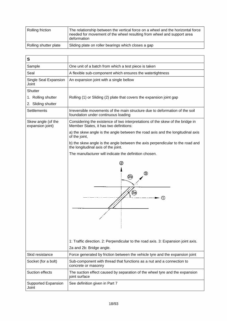
Skew angle (of theexpansion joint)
Considering the existence of two interpretations of the skew of the bridge inMember States, it has two definitions:
a) the skew angle is the angle between the road axis and the longitudinal axisof the joint,
b) the skew angle is the angle between the axis perpendicular to the road andthe longitudinal axis of the joint.
The manufacturer will indicate the definition chosen.
1: Traffic direction. 2: Perpendicular to the road axis. 3: Expansion joint axis.
2a and 2b: Bridge angle.
Skid resistance Force generated by friction between the vehicle tyre and the expansion joint
Socket (for a bolt) Sub-component with thread that functions as a nut and a connection toconcrete or masonry
Suction effects The suction effect caused by separation of the wheel tyre and the expansionjoint surface
Supported ExpansionJoint
See definition given in Part 7
19/93
TTemperature See operating temperature
Template An auxiliary structure which ensures the right positioning of fixing elements in aconcrete structure or the right positioning of drilled holes
Test piece Part of the sample from which test specimens are taken
Test specimen Piece of accurate dimension taken from test piece
Traffic All road users: vehicles, cyclists, motorists, equestrians, pedestrians
Traffic classes Vehicle and other user categories with similar effects or loads on the expansionjoint
Transition strip Filler material between the expansion joint and the adjacent surfacing
UUpstand The vertical or inclined part of the joint which ensures continuity of the joint
between road surface level and footway level
VVoid An opening in the road surface (generally defined by two dimensions) with no
bearing capacity
WWear The loss of material due to friction between two parts of the expansion joint or
between a part of the expansion joint and the structure
3.2.2 Abbreviations
See Annex G.

20/93
Section two:GUIDANCE FOR THE ASSESSMENT OF
THE FITNESS FOR USE
GENERAL NOTES
(a) Applicability of the ETAG
This ETAG provides guidance on the assessment of a family of Road Bridge Expansion Joints andtheir intended uses. It is the manufacturer or producer who defines the expansion joint for which he isseeking an ETA and how it is to be used in the works, and consequently the scale of the assessment.
It is therefore possible that for some Road Bridge Expansion Joint, which are fairly conventional, onlysome of the tests and corresponding criteria are sufficient to establish fitness for use. In other cases,e.g. special or innovative Road Bridge Expansion Joint or materials, or where there is a range of uses,the whole package of tests and assessment may be applicable.
(b) General lay out of this section
The assessment of the fitness of Road Bridge Expansion Joints with regard to their fitness for intendeduse in construction works is a process described in three main chapters:
- Chapter 4 clarifies the specific requirements for the works relevant to the Road BridgeExpansion Joint and uses concerned, beginning with the Essential Requirements for works (CPDArticle 11.2) and then listing the corresponding relevant characteristics of Road Bridge ExpansionJoint.
- Chapter 5: extends the list in chapter 4 into more precise definitions and the methodsavailable to verify product characteristics and to indicate how the requirements and the relevantproduct characteristics are described. This is done by test procedures, methods of calculation and ofproof, etc. (selection of the appropriate methods).
- Chapter 6 provides guidance on the assessing and judging methods to confirm fitness forthe intended use of the Road Bridge Expansion Joint.
Chapter 7, assumptions and recommendations are only relevant in as far as they concern the basisupon which the assessment of the Road Bridge Expansion Joint is made concerning their fitness forthe intended use.
(c) Levels or classes related to the essential requirements and to the product performance (seeeach ID clause 1.2 and EC Guidance Paper E)
According to the CPD "Classes" in this ETAG refer only to mandatory levels or classes laid down, inthe EC-mandate.
This ETAG indicates the compulsory way of expressing relevant performance characteristics for theRoad Bridge Expansion Joint. If, for some uses at least one Member State has no regulations, amanufacturer always has the right to opt out of one or more of them, in which case the ETA will state"no performance determined" against that aspect, except for those properties for which, when nodetermination has been made, the Road Bridge Expansion Joint no longer falls under the scope of theETAG; such cases shall be indicated in the ETAG.

21/93
(d) Working life (durability) and serviceability
The provisions, test and assessment methods in this Guideline or referred to, have been written,based upon the assumed intended working life of the Road Bridge Expansion Joint for the intendeduse according to 2.3.4, provided that the Road Bridge Expansion Joint is subject to appropriate useand maintenance (cf. Chapter 7). These provisions are based upon the current state of the art and theavailable knowledge and experience.
An "assumed intended working life" means that it is expected that, when an assessment following theETAG-provisions is made, and when this working life has elapsed, the real working life may be, innormal use conditions, considerably longer without major degradation affecting the essentialrequirements.
The indications given as to the working life of a Road Bridge Expansion Joint cannot be interpreted asa guarantee given by the producer or the Approval Body. They should only be regarded as a means forthe specifiers to choose the appropriate criteria for Road Bridge Expansion Joint in relation to theexpected, economically reasonable working life of the works (based upon each ID par. 5.2.2).
(e) Fitness for the intended use
According to the CPD it has to be understood that within the terms of this ETAG, products shall "havesuch characteristics that the works in which they are to be incorporated, assembled, applied orinstalled, can, if properly designed and built, satisfy the Essential Requirements" (CPD, Article 2.1).
Hence, the Road Bridge Expansion Joint "must be suitable for use in construction works which (as awhole and in their separate parts) are fit for their intended use, account being taken of economy, andin order to satisfy the essential requirements. Such requirements must, subject to normalmaintenance, be satisfied for an economically reasonable working life. The requirements generallyconcern actions which are foreseeable." (CPD Annex I, preamble).
22/93
4. REQUIREMENTS
for works, and their relationship to the Road Bridge Expansion Jointcharacteristics
This chapter sets out the aspects of performance to be examined in order to satisfy the relevantEssential Requirements, by:
- expressing in more detail, within the scope of the ETAG, the relevant Essential Requirementsof the CPD in the Interpretative Documents and in the mandate, for works or parts of theworks, taking into account the actions to be considered, as well as the expected durability andserviceability of the works,
- applying them to the scope of the ETAG (product and where appropriate its constituents,components and intended uses), and providing a list of relevant Road Bridge Expansion Jointcharacteristics and other applicable properties.
When a product characteristic or other applicable property is specific to one of the EssentialRequirements, it is dealt with in the appropriate place. If, however, the characteristic or property isrelevant to more than one Essential Requirement, it is addressed under the most relevant one withcross-reference to the other(s). This is especially important where a manufacturer claims "Noperformance determined" for a characteristic or property under one Essential Requirement and it iscritical for the assessing and judging under another Essential Requirement. Similarly, characteristics orproperties which have a bearing on durability assessments may be dealt with under ER 1, ER 3 andER 4, with reference under 4.7. Where there is a characteristic which only relates to durability, this isdealt with in 4.7.
This chapter also takes into account further requirements, if any (e.g. resulting from other ECDirectives) and identifies aspects of serviceability including specifying characteristics needed to identifythe Road Bridge Expansion Joint.
23/93
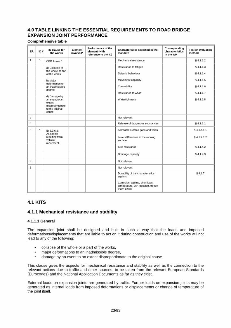
4.0 TABLE LINKING THE ESSENTIAL REQUIREMENTS TO ROAD BRIDGEEXPANSION JOINT PERFORMANCEComprehensive table
ER ID # ID clause forthe works
Elementinvolved*
Performance of theelement (withreference to the ID)
Characteristics specified in themandate
Correspondingcharacteristicsin the WP
Test or evaluationmethod
1 1 CPD Annex 1
a) Collapse ofthe whole or partof the works.
b) Majordeformation toan inadmissibledegree.
d) Damage byan event to anextentdisproportionateto the originalcause.
Mechanical resistance § 4.1.1.2
Resistance to fatigue § 4.1.1.3
Seismic behaviour § 4.1.1.4
Movement capacity § 4.1.1.5
Cleanability § 4.1.1.6
Resistance to wear § 4.1.1.7
Watertightness § 4.1.1.8
2 Not relevant
3 Release of dangerous substances § 4.1.3.1
4 4 ID 3.3.6.2:Accidentsresulting fromvehiclemovement.
Allowable surface gaps and voids § 4.1.4.1.1
Level differences in the runningsurface
§ 4.1.4.1.2
Skid resistance § 4.1.4.2
Drainage capacity § 4.1.4.3
5 Not relevant
6 Not relevant
Durability of the characteristicsagainst:
Corrosion, ageing, chemicals,temperature, UV-radiation, freeze-thaw, ozone
§ 4.1.7
4.1 KITS
4.1.1 Mechanical resistance and stability
4.1.1.1 General
The expansion joint shall be designed and built in such a way that the loads and imposeddeformations/displacements that are liable to act on it during construction and use of the works will notlead to any of the following:
collapse of the whole or a part of the works, major deformations to an inadmissible degree, damage by an event to an extent disproportionate to the original cause.
This clause gives the aspects for mechanical resistance and stability as well as the connection to therelevant actions due to traffic and other sources, to be taken from the relevant European Standards(Eurocodes) and the National Application Documents as far as they exist.
External loads on expansion joints are generated by traffic. Further loads on expansion joints may begenerated as internal loads from imposed deformations or displacements or change of temperature ofthe joint itself.
24/93
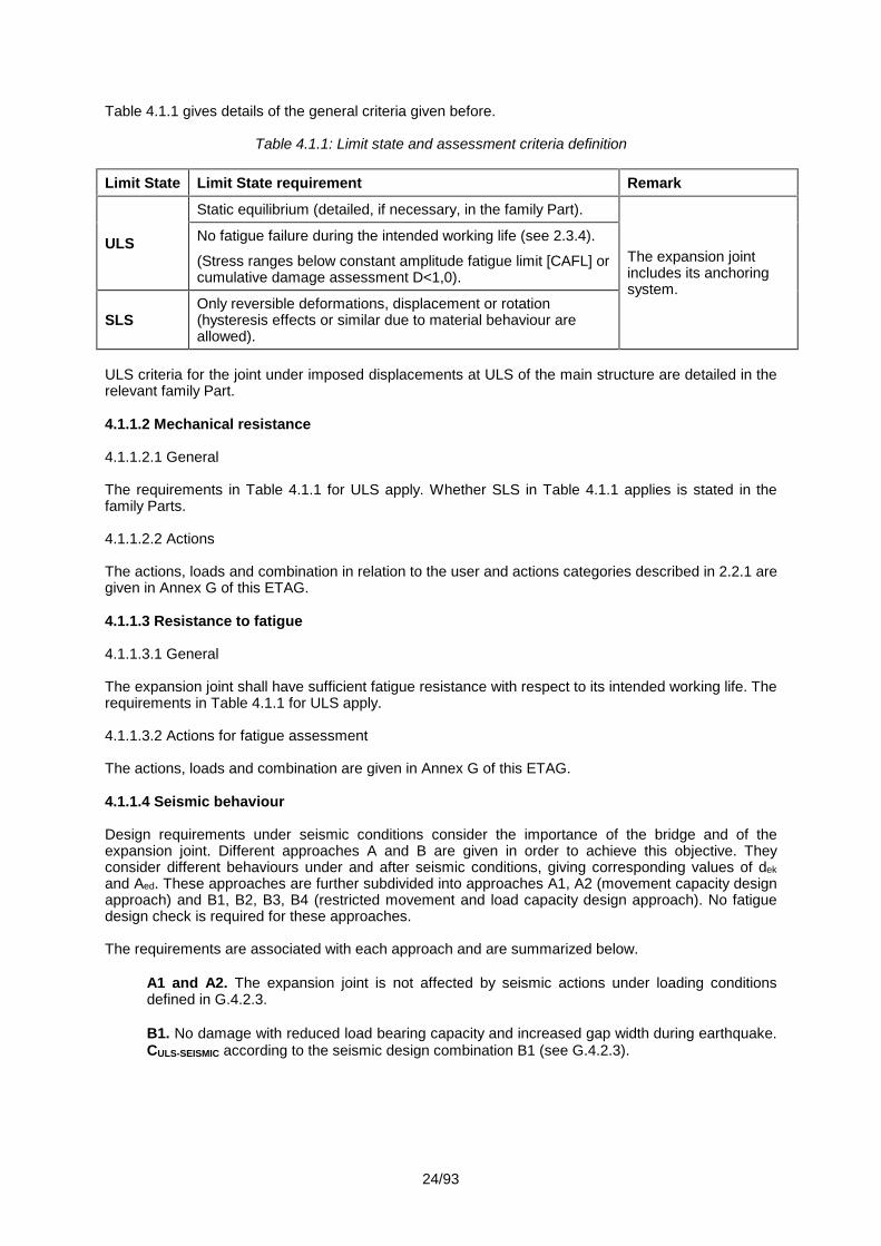
Table 4.1.1 gives details of the general criteria given before.
Table 4.1.1: Limit state and assessment criteria definition
Limit State Limit State requirement Remark
ULS
Static equilibrium (detailed, if necessary, in the family Part).
The expansion jointincludes its anchoringsystem.
No fatigue failure during the intended working life (see 2.3.4).
(Stress ranges below constant amplitude fatigue limit [CAFL] orcumulative damage assessment D<1,0).
SLSOnly reversible deformations, displacement or rotation(hysteresis effects or similar due to material behaviour areallowed).
ULS criteria for the joint under imposed displacements at ULS of the main structure are detailed in therelevant family Part.
4.1.1.2 Mechanical resistance
4.1.1.2.1 General
The requirements in Table 4.1.1 for ULS apply. Whether SLS in Table 4.1.1 applies is stated in thefamily Parts.
4.1.1.2.2 Actions
The actions, loads and combination in relation to the user and actions categories described in 2.2.1 aregiven in Annex G of this ETAG.
4.1.1.3 Resistance to fatigue
4.1.1.3.1 General
The expansion joint shall have sufficient fatigue resistance with respect to its intended working life. Therequirements in Table 4.1.1 for ULS apply.
4.1.1.3.2 Actions for fatigue assessment
The actions, loads and combination are given in Annex G of this ETAG.
4.1.1.4 Seismic behaviour
Design requirements under seismic conditions consider the importance of the bridge and of theexpansion joint. Different approaches A and B are given in order to achieve this objective. Theyconsider different behaviours under and after seismic conditions, giving corresponding values of dekand Aed. These approaches are further subdivided into approaches A1, A2 (movement capacity designapproach) and B1, B2, B3, B4 (restricted movement and load capacity design approach). No fatiguedesign check is required for these approaches.
The requirements are associated with each approach and are summarized below.
A1 and A2. The expansion joint is not affected by seismic actions under loading conditionsdefined in G.4.2.3.
B1. No damage with reduced load bearing capacity and increased gap width during earthquake.CULS-SEISMIC according to the seismic design combination B1 (see G.4.2.3).

25/93
B2. Minor damage to secondary sub-components and non load carrying sub-components. Loadcarrying sub-components are allowed to have a reduced load bearing capacity and increasedgap width under the seismic design situation.
Secondary sub-components and non load carrying sub-components (e.g. seal sub-components)are allowed to be damaged. Both of these sub-components shall be replaceable or repairableafter the earthquake. For the other design requirements see approach B1.
B3. Minor damage to primary sub-components or fusible devices due to a combination ofreduced traffic load bearing capacity and increased gap width during earthquake. The resistanceof load carrying structural elements shall be checked for the seismic design situation CULS-SEISMIC(see G.4.2.3).
The expansion joint is assumed to be resistant to frequent traffic loads according to EN 1990after the earthquake and to fulfil all the Ultimate and Serviceability Limit State requirements aftersmall repairs.
The sub-components with minor damage shall be easily replaceable with no need of immediaterepair.
B4. Major damage to fusible devices and minor damage on the joint. No remaining load bearingcapacity and increased gap width after the earthquake.
The combinations of loads defined in G.4.2.3 shall be used to verify the resistance of loadcarrying structural elements during the earthquake.
The detailing of expansion joint parts to be damaged during the design seismic event has to beprovided with the predictable mode of failure.
The possibility of permanent repair shall be described.
These fusible devices should avoid or minimize damage on the structural elements of the bridgereducing at the mean time the required size of the expansion joint.
In the case of emergency traffic after the seismic event, the expansion joint shall comply with approachB3 load carrying requirements and the width (in the traffic direction) of possible gaps shall be as amaximum 300 mm.
Note: Occurring level differences may cause the need for temporary measures enabling theemergency vehicles to pass the joint at slow speed. Short-term repairs may be required.
26/93
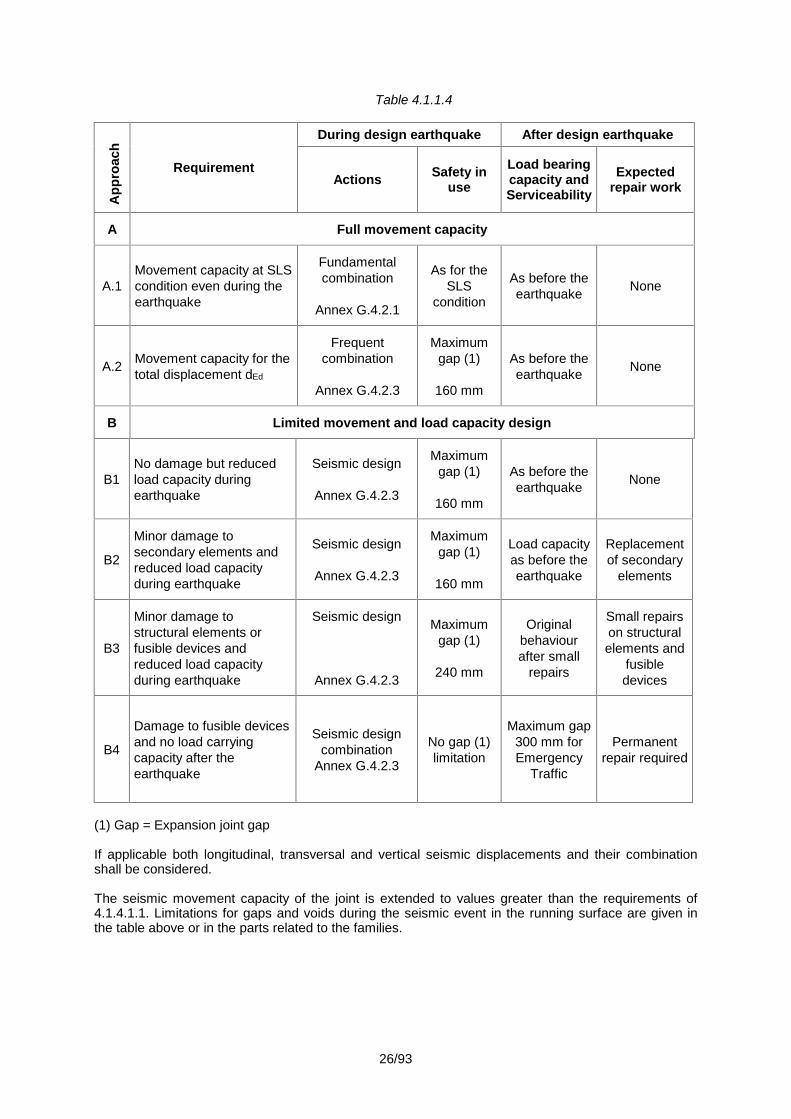
Table 4.1.1.4A
ppro
ach
Requirement
During design earthquake After design earthquake
Actions Safety inuse
Load bearingcapacity andServiceability
Expectedrepair work
A Full movement capacity
A.1Movement capacity at SLScondition even during theearthquake
Fundamentalcombination
Annex G.4.2.1
As for theSLS
condition
As before theearthquake None
A.2 Movement capacity for thetotal displacement dEd
Frequentcombination
Annex G.4.2.3
Maximumgap (1)
160 mm
As before theearthquake None
B Limited movement and load capacity design
B1No damage but reducedload capacity duringearthquake
Seismic design
Annex G.4.2.3
Maximumgap (1)
160 mm
As before theearthquake None
B2
Minor damage tosecondary elements andreduced load capacityduring earthquake
Seismic design
Annex G.4.2.3
Maximumgap (1)
160 mm
Load capacityas before theearthquake
Replacementof secondary
elements
B3
Minor damage tostructural elements orfusible devices andreduced load capacityduring earthquake
Seismic design
Annex G.4.2.3
Maximumgap (1)
240 mm
Originalbehaviourafter small
repairs
Small repairson structuralelements and
fusibledevices
B4
Damage to fusible devicesand no load carryingcapacity after theearthquake
Seismic designcombination
Annex G.4.2.3
No gap (1)limitation
Maximum gap300 mm forEmergency
Traffic
Permanentrepair required
(1) Gap = Expansion joint gap
If applicable both longitudinal, transversal and vertical seismic displacements and their combinationshall be considered.
The seismic movement capacity of the joint is extended to values greater than the requirements of4.1.4.1.1. Limitations for gaps and voids during the seismic event in the running surface are given inthe table above or in the parts related to the families.

27/93
4.1.1.5 Movement capacity
The nominal movement capacity of an expansion joint is the possibility to allow the displacement of theparts of the main structure under unloaded and loaded conditions as given in Annex G.
The movement capacity shall be assessed for 3 directions: longitudinal, transversal and vertical.
The displacement velocity and the temperature may affect the response of the different joints. Theinfluence of these parameters is addressed in Parts 2 to 8 where relevant.
Where relevant, additional allowance for displacements and corresponding rotation is specified in thefamily Parts.
The declared movement capacity is accompanied by a declaration of the minimum opening position.
4.1.1.6 Cleanability
The proper functioning of the expansion joint shall not be affected by accumulation of debris. Thecleanability can either be achieved by a good design or by good accessibility to allow removal of debris.
Sufficient accessibility to the drainage system for flushing and maintenance shall be provided.
4.1.1.7 Resistance to wear
The intended working life of the kit shall not be affected by wear which is caused by movements eitherbetween two parts of the joint or between parts of the joint and the main structure.
Components with a shorter assumed working life than the kit, caused by wear, shall be replaceable.
Where relevant, the influence of the wear is addressed in Parts 2 to 8 and shall be stated in the ETA.
4.1.1.8 Watertightness
The main structure and where relevant the sub-components of the joint under the running surface shallbe protected from water and its chemical contents.
There are two alternatives:
- by a watertight joint itself,- or by a sub-surface drainage system.
4.1.2 Safety in case of fire
Not relevant.
4.1.3 Hygiene, health and environment
4.1.3.1 Release of dangerous substances
The expansion joint shall be such that, when installed according to the appropriate provisions of theMember States, it allows for the satisfaction of the ER3 of the CPD as expressed by the nationalprovisions of the Member States and in particular does not cause harmful emission of toxic gases,dangerous particles or radiation to the indoor environment nor contamination of the outdoorenvironment (air, soil or water).
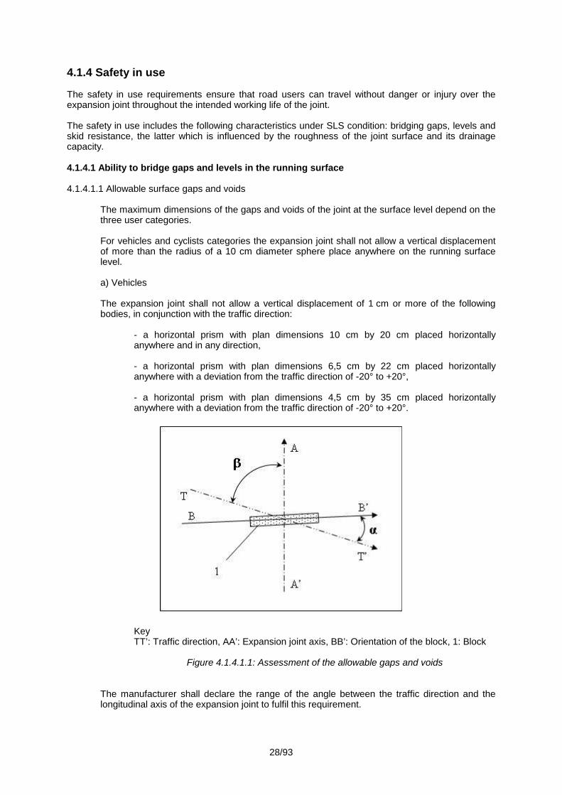
28/93
4.1.4 Safety in use
The safety in use requirements ensure that road users can travel without danger or injury over theexpansion joint throughout the intended working life of the joint.
The safety in use includes the following characteristics under SLS condition: bridging gaps, levels andskid resistance, the latter which is influenced by the roughness of the joint surface and its drainagecapacity.
4.1.4.1 Ability to bridge gaps and levels in the running surface
4.1.4.1.1 Allowable surface gaps and voids
The maximum dimensions of the gaps and voids of the joint at the surface level depend on thethree user categories.
For vehicles and cyclists categories the expansion joint shall not allow a vertical displacementof more than the radius of a 10 cm diameter sphere place anywhere on the running surfacelevel.
a) Vehicles
The expansion joint shall not allow a vertical displacement of 1 cm or more of the followingbodies, in conjunction with the traffic direction:
- a horizontal prism with plan dimensions 10 cm by 20 cm placed horizontallyanywhere and in any direction,
- a horizontal prism with plan dimensions 6,5 cm by 22 cm placed horizontallyanywhere with a deviation from the traffic direction of -20° to +20°,
- a horizontal prism with plan dimensions 4,5 cm by 35 cm placed horizontallyanywhere with a deviation from the traffic direction of -20° to +20°.
KeyTT’: Traffic direction, AA’: Expansion joint axis, BB’: Orientation of the block, 1: Block
Figure 4.1.4.1.1: Assessment of the allowable gaps and voids
The manufacturer shall declare the range of the angle between the traffic direction and thelongitudinal axis of the expansion joint to fulfil this requirement.
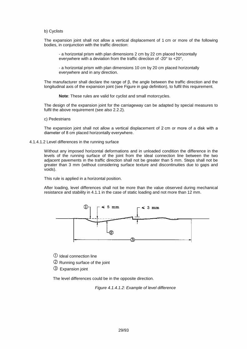
29/93
b) Cyclists
The expansion joint shall not allow a vertical displacement of 1 cm or more of the followingbodies, in conjunction with the traffic direction:
- a horizontal prism with plan dimensions 2 cm by 22 cm placed horizontallyeverywhere with a deviation from the traffic direction of -20° to +20°,
- a horizontal prism with plan dimensions 10 cm by 20 cm placed horizontallyeverywhere and in any direction.
The manufacturer shall declare the range of , the angle between the traffic direction and thelongitudinal axis of the expansion joint (see Figure in gap definition), to fulfil this requirement.
Note: These rules are valid for cyclist and small motorcycles.
The design of the expansion joint for the carriageway can be adapted by special measures tofulfil the above requirement (see also 2.2.2).
c) Pedestrians
The expansion joint shall not allow a vertical displacement of 2 cm or more of a disk with adiameter of 8 cm placed horizontally everywhere.
4.1.4.1.2 Level differences in the running surface
Without any imposed horizontal deformations and in unloaded condition the difference in thelevels of the running surface of the joint from the ideal connection line between the twoadjacent pavements in the traffic direction shall not be greater than 5 mm. Steps shall not begreater than 3 mm (without considering surface texture and discontinuities due to gaps andvoids).
This rule is applied in a horizontal position.
After loading, level differences shall not be more than the value observed during mechanicalresistance and stability in 4.1.1 in the case of static loading and not more than 12 mm.
Ideal connection line Running surface of the joint Expansion joint
The level differences could be in the opposite direction.
Figure 4.1.4.1.2: Example of level difference
30/93
4.1.4.2 Skid resistance
The design of the joint and its trafficked surface shall be such that under normal condition no hazardwill be caused to the road users.
a) Carriageway
For flat surfaces larger than a 150 x 150 mm square without relief (surface texture) in excess of 1,2 mm testing is required.
b) Footpath
For flat surfaces larger than a 150 x 150 mm square without relief (surface texture) in excess of 1,2 mm and the requirement is not met by special design (e.g. chequered plate) verification bytesting is required.
4.1.4.3 Drainage capacity
The design of the joint shall prevent standing water, from rain or melting snow.
This requirement may be met by the transverse slope of the running surface. When required by aMember State’s regulation, a drainage system shall be provided. Drainage can be achieved by surfaceand/or sub-surface drainage systems.
4.1.5 Protection against noise
Not relevant.
4.1.6 Energy economy and heat retention
Not relevant.
4.1.7 Aspects of durability, serviceability and identification of the products
This sub-section contains requirements as far as necessary for the satisfaction of the CPD not coveredby 4.1.1 to 4.1.6.
4.1.7.1 Aspects of durability
The durability of the expansion joint depends mainly on the durability of its components, the materialsused, the achieved quality at manufacture and the achieved quality of installation and the propermaintenance.
The expansion joint shall have sufficient resistance to the effects of potential degradation factors toensure that deterioration of materials and components during the intended working life does notsignificantly affect the performance of the kit in relation to fulfilling all the Essential Requirements 1, 3and 4.
The aspects related to the durability of a Road Bridge Expansion Joint, and which shall be taken intoaccount, are:
Corrosion
Unless intrinsically corrosion resistant, metallic components for products according to the differentfamily parts are considered to be affected by corrosion and all metallic surfaces have to be protected.
The atmospheric corrosivity categories to be considered are C4, C5-I or C5-M according toEN ISO 12944-2, whereas for the durability of the protective paint system the durability ranges“medium (M)” or “high (H)” according to EN ISO 12944-5 apply, depending on the declared working lifecategory according to 2.3.4 in this Part 1 of ETAG 032.

31/93
Structural steel surfaces in contact with concrete shall have no coating. Only at the transitions anoverlap of approximately 50 mm of the full corrosion protection system shall be applied.
The provision regarding the durability range, made in the European Technical Approval, is not a“guarantee time”. This shall be stated in the European Technical Approval.
In case of use of stainless steel for components, the grade of steel shall be 1.4401, 1.4404 or 1.4571in accordance with EN 10088, or equivalent (e.g. EN ISO 3506 for stainless steel bolts).
Aluminium alloys shall have a corrosion resistance of at least category “B” according to ISO 3522,Table C.1, or equivalent. Furthermore, interaction between concrete and the aluminium alloy shall beprevented.
Permanent steel bolts shall at least be:
- electrolytic zinc plated, then after tightening coated with Fe/Zn 25 in acc. with EN ISO 2081 or- hot dip galvanized in accordance with EN ISO 10684.
or be made of:
- austenitic steel in accordance with EN ISO 3506 with grade A2 or higher for non marine (non-saline) environment and grade A4 or higher for marine (saline) environment.
Temporary bolts may be unprotected.
Chemicals
The concentration of oil, petrol, fuel oil or de-icing salts on a bridge under normal service conditionsshall not affect the expansion joint durability.
Loss of performance due to ageing resulting from temperature, UV radiation and ozone
The required performance of the expansion joint shall not be affected by ageing. This applies toelastomer and plastic components (as defined in the relevant family Part) for temperature and forozone. This applies also for a layer of resin exposed to direct UV ray when its thickness is less than1 mm.
Resistance against freeze-thaw
Susceptibility of porous materials (e.g. concrete mortar) to freeze-thaw damage
Durability aspects of other materials shall be demonstrated by the manufacturer in a suitablemanner
Other aspects of durability not stated above are determined in the family Part, if relevant.
The fatigue and wear aspects are covered in 4.1.1.3 and 4.1.1.7.
4.1.7.2 Aspects of serviceability
The manufacturer shall submit information for the installation, inspection and maintenance to theApproval Body.
Components indicated in the ETA with a shorter assumed working life than the expansion joint shall beaccessible for inspection and shall be replaceable.
Guidance for accessibility for inspection of the expansion joint is given in the family Part, whererelevant.
4.1.7.3 Aspects of identification
The expansion joint and/or its components shall be identified (marking is covered in 8.4). The aspectsto be identified are given in the relevant family Parts.

32/93
4.2 COMPONENTS
The components may consist of smaller parts which are called sub-components. These Sub-components may be standardized products or special products developed of specified materials. Theyare assembled in the factory production process to form the component.
The manufacturer shall declare the components that are included in the kit and shall specify the sub-components and material characteristics and, where applicable, their tolerances. Detailedrequirements are stated in the relevant family Parts.
It shall be indicated which components or which sub-components are replaceable.

33/93
5. METHODS OF VERIFICATION
This chapter refers to the verification methods used to determine the various aspects of performanceof the expansion joints in relation to the requirements for the works (calculations, tests, engineeringknowledge, site experience, etc.) as set out in Chapter 4.
The possibility exists to use existing data in accordance with the EOTA Guidance Document No 004 on“The provision of data for assessment leading to ETA”.
When EUROCODES are quoted in this ETAG as the methods for the verification of certaincharacteristics, their application in this ETAG, as well as in the subsequent ETAs issued according tothis ETAG, shall be in accordance with the principles laid down in the EC Guidance Paper on the useof EUROCODES in harmonised European technical specifications.
5.0 GENERAL
ER ID clause for the worksCharacteristics specified in themandate and correspondingcharacteristics in the WP
Test or evaluation method
1 CPD Annex 1
a) Collapse of the whole or partof the work.
b) Major deformation to aninadmissible degree.
d) Damage by an event to anextent disproportionate to theoriginal cause.
Mechanical resistance § 5.1.1.2
Resistance to fatigue § 5.1.1.3
Seismic behaviour § 5.1.1.4
Movement capacity § 5.1.1.5
Cleanability § 5.1.1.6
Resistance to wear § 5.1.1.7
Watertightness § 5.1.1.8
2 Not relevant
3 Release of dangerous substances § 5.1.3
4 ID 3.3.6.2: Accidents resultingfrom vehicle movement.
Allowable surface gaps and voids § 5.1.4.1.1
Level differences in the running surface § 5.1.4.1.2
Skid resistance § 5.1.4.2
Drainage capacity § 5.1.4.3
5 Not relevant
6 Not relevant
Durability of the characteristics against:
Corrosion, ageing, chemicals,temperature, UV-radiation, freeze-thaw,ozone
§ 5.1.7.1
5.1 KITS
5.1.1 Mechanical resistance and stability
5.1.1.1 General
For the verification of mechanical resistance, resistance to fatigue and wear, the methods given in thisETAG shall be used. These methods may need to be supplemented by reference to additionalstandards (EN or ISO standards or national standards). In the absence of standards, assessmentprocedures, appropriate (as agreed by the Approval Body and the manufacturer) to prove thesecharacteristics, shall be used.
34/93
5.1.1.2 Mechanical resistance
Mechanical resistance shall be demonstrated by calculations, testing or a combination of both. Thedesign loads shall be derived from the traffic loads in Chapter 4 and Annex G.
5.1.1.2.1 Calculations
The structure shall be modelled in such a way that the model represents the real structure.
The partial factors M shall be determined either:
- in accordance with 6.3 of EN 1990:2003 and,- where relevant, using the recommended values given in the relevant Eurocode, or its
national annex.
The value used by the manufacturer shall be declared in the ETA.
It is allowed to calculate the 3-dimensional behaviour with 2-dimensional models when care istaken that the appropriate boundary conditions and eccentricities are used. When springs arerepresented by rigid supports, the assumption shall be justified by parameter calculations.
5.1.1.2.2 Testing
The manufacturer and the Approval Body shall define an appropriate regime which allows theperformance to be derived from testing in an appropriate manner. Any of the testing typesgiven in Annex D.3 (1) of EN 1990:2003 may be applied.
Note: In cases where the interpretation of the principles of EN 1990 for similar ETAapplications might lead to different approaches in obtaining the product performances,it is recommended to consult Approval Bodies, working in the same field, on the testregime.
The test specimen dimensions and the boundary conditions shall be selected in such a waythat the structural behaviour complies with the behaviour in a real structure.
The test loads shall be derived from Annex G.
The test methods are given in the family Parts.
5.1.1.3 Resistance to fatigue
Fatigue resistance shall be demonstrated by calculation, testing or a combination of both. The designloads shall be determined using the traffic loads in Chapter 4 and Annex G, whereas for the loaddistribution, either the distribution given in Annex G applies or if results from dynamic tests showanother load distribution, this distribution may be used.
Where relevant due to the design, the dynamic response of the expansion joint, due to unevenness oftheir running surface and dynamic interaction such as upswing and damping, shall be considered. Forthis aspect, the possibilities, in each relevant family Part, are the following:
a) Reduce the amplification factor.b) Modify the number of cycles.
Based on:
- Specific analysis of the expansion joint, case by case (see also Annex G, G.3.3),- Statement covering all the products in the relevant Part.
Note: The fatigue resistance assessment procedure may differ for each family.
35/93
5.1.1.3.1 Calculations
The partial factors for fatigue shall be determined either:
- in accordance with 6.3 of EN 1990:2003, or,- where relevant, using the recommended values given in the relevant Eurocode, or its national
annex.
The value used by the manufacturer shall be declared in the ETA.
The structure shall be modelled in such a way that the model gives reliable results for the intendedworking life.
It is allowed to calculate the intended working life with fatigue detail classifications determined inaccordance with EN 1993-1-9 and EN 1993-2.
5.1.1.3.2 Testing
It is not possible to give definitive guidance for the derivation of mechanical resistance based ontesting, because this depends on many factors such as the design of the joint, the design of the test,and existing knowledge about the material and/or component properties.
Note: In cases where the interpretation of the principles of EN 1990 for similar ETAapplications might lead to different approaches in obtaining the product performances, it isrecommended to consult Approval Bodies, working in the same field, on the test regime.
The manufacturer and the Approval Body shall define an appropriate regime which allows theperformance to be derived from testing in an appropriate manner. Any of the testing types given inAnnex D.3 (1) of EN 1990:2003 may be applied.
The test specimen dimensions and the boundary conditions shall be selected in such a way that thestructural behaviour complies with the behaviour in a real structure.
The test loads shall be derived from Annex G.
The test methods are given in the family Parts.
5.1.1.4 Seismic behaviour
The seismic behaviour shall be demonstrated for the selected approach given in Chapter 4 and/or byanalysis of the design of the expansion joint using the principles of Annex J and EN 1998-2.
5.1.1.5 Movement capacity
The nominal movement capacity under unloaded conditions declared by the manufacturer shall bedemonstrated.
The nominal movement capacity shall be verified by testing. The test method is described in Annex K.
Where relevant, due attention shall be paid to the rotations. The verification of this phenomenon will inmost cases be limited to an analysis of the design.
Note: Some types of joints may not need testing for movement capacity evaluation, e.g. jointswithout a connection between the two parts of the main structure like a seal.
5.1.1.6 Cleanability
Cleanability shall be verified by check of the design principles or, in case of doubt about theperformance of the proposed design, by an additional test to the test of the movement capacity, bydepositing sand on the joint and verifying the removal of the sand under opening/closing movements ofthe joint.

36/93
As an alternative, a good accessibility for cleaning has to be verified by analysis of the technical file ofthe expansion joint.
Note: It is recommended to take into account experience with existing products for theverification.
The details of the method of assessment and the results (e.g. “pass” according to the method used),together with any measures that need to be taken to maintain the cleanliness, shall be given in theevaluation report.
5.1.1.7 Resistance to wear
The resistance to wear shall be demonstrated by testing as defined in the relevant family Parts.
5.1.1.8 Watertightness
For the verification of the watertightness of the joint itself, the test method is described in Annex L.
Where a watertight connection between the waterproofing system of the main structure and theexpansion joint exists, this shall be assessed. The verification shall be carried out during thewatertightness verification of the joint itself using Annex L, but including, in the test specimen, thisconnection and a representative portion of the waterproofing system of the main structure. The type ofthe connection shall be described in the ETA.
Note: When a joint has a sub-surface drainage system, its drainage capacity is verifiedaccording to 5.1.4.3.
5.1.2 Safety in case of fire
Not relevant.
5.1.3 Hygiene, health and environment
5.1.3.1 Presence of dangerous substances in the product
The applicant shall submit a written declaration stating whether or not the product/kit containsdangerous substances according to European and national regulations, when and where relevant inthe Member States of destination, and shall list these substances.
5.1.3.2 Compliance with the applicable regulations
If the product/kit contains dangerous substances as declared above, the ETA will provide themethod(s) which has been used for demonstrating compliance with the applicable regulations in theMember States of destination, according to the EU data-base (method(s) of content or release, asappropriate).
5.1.3.3 Application of the precautionary principle
An EOTA member has the possibility to provide to the other members, through the Secretary General,warning about substances which, according to Health authorities of its country, are considered to bedangerous under sound scientific evidence, but are not yet regulated. Complete references about thisevidence will be provided.
This information once agreed upon, will be kept in an EOTA data base, and will be transferred to theCommission services.
The information contained in this EOTA data base will also be communicated to any ETA applicant.
On the basis of this information, a protocol of assessment of the product, regarding this substance,could be established on request of a manufacturer with the participation of the Approval Body whichraised the issue.

37/93
5.1.4 Safety in use
5.1.4.1 Ability to bridge gaps and levels in the running surface
5.1.4.1.1 Allowable surface gaps and voids
Verification shall be carried out by analysis of the technical file and, when needed, by use ofmeasurements tools given to 4.1.4.1.1.
5.1.4.1.2 Level differences in the running surface
Verification shall be carried out by analysis of the technical file and drawings of the expansion joint. Forother related or additional requirements, to be stated in the family Part according to 4.1.4.1.2, theverification method is given in the family Part.
5.1.4.2 Skid resistance
If required, the skid resistance of the expansion joint shall be verified by the portable skid resistancependulum tester as described in EN 13036-4 using the CEN Rubber slider for carriageways and the 4Srubber slider for footpaths. For both, the normal slider width of 76,2 mm shall be used.
If the test method according to EN 13036-4 is not applicable, either a different appropriate test methodshall be used, or the manufacturer shall give an alternative specification of how skid resistance issatisfied. The details and the correlation with EN 13036-4 shall be given in the evaluation report.
5.1.4.3 Drainage capacity
If relevant, the discharge capacity (for closed and maximum opening) shall be assessed either bycalculation (based on analysis of technical file and drawings) or testing.
5.1.5 Protection against noise
Not relevant.
5.1.6 Energy economy and heat retention
Not relevant.
5.1.7 Aspects of durability, serviceability and identification of the products
This sub-section contains requirements as far as necessary for the satisfaction of the CPD not coveredby 5.1.1 to 5.1.6.
5.1.7.1 Aspects of durability
The assessment of the durability can be carried out by direct or indirect testing, historical data,prescriptive description of component materials and design, taking into account the influence ofclimatic conditions, etc.
5.1.7.1.1 Corrosion
The selected corrosion protection system shall be verified according to the relevant standards,indicated in 4.1.7.1.1.
For structural steel surfaces in contact with concrete it shall be verified that the corrosion protectionlayout for the concerned kit conforms to the requirement according to 4.1.7.1. In addition, therequested overlap according to 4.1.7.1 shall be verified according to the technical drawings.
The equivalence of alternative aluminium alloys shall be verified by means of the relevant standards(see EN 1706, EN 573, ISO 209 etc.).

38/93
It shall be verified by proof of the indications of the manufacturer in the technical documentation, thatno interaction between aluminium and concrete can take place.
For steel bolts it shall be verified that the selected materials and system for corrosion protectionconform to the requirements given in 4.1.7.1.
The effect of galvanic corrosion shall be considered by checking the design of the expansion joint(reference 8.3).
5.1.7.1.2 Chemicals
The assessment shall be based on common knowledge and/or experience which can be demonstratedwith reference to EN, ISO and/or national standards, national approvals of expansion joint or similarmaterial/component.
Alternatively, the assessment shall be based on testing (laboratory or field).
The accidental condition shall not be taken into account.
Note: For de-icing salts see also 5.1.7.1.4 below.
5.1.7.1.3 Ageing resulting from UV radiation, temperature and ozone
Materials may be susceptible to UV radiation, temperature, and ozone degradation. Where relevant,take into consideration:
a) Temperature
To check the sensitivity of the elastomer or plastic to elevated temperature, the material shall besubjected to test method ISO 188 (Method A) for elastomer or EN ISO 11403-3 (6.5, exposure to heatcondition) for plastic. The minimal conditions of exposure are the following: 14 days at a temperature of70 °C (temperature and time shall be defined depending on the elastomer composition, see ISO 471).The hardness is measured according to ISO 7619, the tensile strength and the elongation at ruptureare measured according to ISO 37.
b) UV ray
Where polymeric material (e.g. polyurethane, epoxy) is exposed to UV-rays and its material propertymight be affected, a test shall be carried out. The test specimen shall be exposed to UV Radiationaccording to the procedure of EOTA Technical Report 010 with the use of fluorescent tubes (UV-A)after 5 000 hours exposure.
c) Ozone
To check the sensitivity of elastomer or plastic to ozone, the material shall undergo a test. The testspecimen shall be verified according to test method ISO 1431-1 (Test procedure A: static condition).The test conditions are the following: 74 hours of exposure at the temperature of 40 °C, with an ozoneconcentration of 50 pphm. The test specimen is submitted to 20 % of elongation. If these testconditions are not applicable, alternative test conditions shall be used and defined in the concernedfamily Part.
The test conditions used shall be stated in the evaluation report.
5.1.7.1.4 - Resistance against freeze-thaw
The degradation of porous materials (e.g. mortar), to freeze-thaw shall be checked by testing. Testspecimen(s) of the material or component shall be subjected to freeze/thaw cycles in accordance withEN 13687-1. According to the use of the product, the number of cycles shall be 50 (see EN 1504-2,Tables 5, line 9 and Table 1, 1.3 and 5.1).

39/93
5.1.7.2 Aspects of serviceability
The information for the installation, inspection and maintenance, given by the manufacturer, shall bechecked by the Approval Body to prove that the assembled joint can be installed, inspected andmaintained.
5.1.7.3 Aspects of identification
Verification of certificates, test reports and labelling.
5.2 COMPONENTS
A non exhaustive list of verification methods is stated in the relevant family Part.
The manufacturer shall indicate the verification methods (certificate, test method, …). Where noappropriate EN or ISO standard is available, the use of national provisions is permitted.

40/93
6. ASSESSING AND JUDGING THE FITNESS OF PRODUCTS FOR ANINTENDED USE
This chapter details the performance requirements to be met (Chapter 4) in precise and measurable(as far as possible and proportional to the importance of the risk) or qualitative terms, related to theexpansion joint and its intended use, using the outcome of the verification methods (Chapter 5).
6.0 TABLE LINKING THE ESSENTIAL REQUIREMENTS TO PRODUCTREQUIREMENTS
ERCharacteristicsspecified in the
mandate
ETAG paragraph onproduct
performance to beassessed
Class, use category, criterionNo performance
determined option
1 Mechanical resistance § 6.1.1.2 Carriageway Pass/fail No
and/or
Footpath
Pass/failNo
and/or options:
- accidental loadon footway
Pass/failNo
- collision on kerb Pass/fail No
Resistance to fatigue § 6.1.1.3 Pass/fail No
Seismic behaviour § 6.1.1.4 Declaration of selected approach andrelevant information (aspects etc.) Yes
Movement capacity § 6.1.1.5 Declared values No
Cleanability § 6.1.1.6 Pass/fail Yes
Resistance to wear § 6.1.1.7 See relevant family Part No
Watertightness § 6.1.1.8 Pass/fail Yes
2 Not relevant
3 Release of dangeroussubstances
§ 6.1.3 Indication of dangerous substances incl.concentration, etc.or"No dangerous substances"
Yes
4 Allowable surfacegaps and voids.
§ 6.1.4.1.1 Gap/voids
For vehicle Pass/fail YesGap for use inlongitudinal axis
Pass/fail Yes
Gap/voids/recess- For cyclist Pass/fail Yes- For pedestrian Pass/fail Yes
Level differences inthe running surface
§ 6.1.4.1.2 Level differencesand steps
Pass/fail Yes
For other relatedor additionalrequirementsdefined in thefamily Parts ifrelevant
Pass/fail ordeclared value,see family Part Yes
Skid resistance § 6.1.4.2 On carriageway Pass/fail ordeclared value Yes
On footpath Pass/fail ordeclared value Yes
Drainage capacity § 6.1.4.3 Declared value Yes
5 Not relevant
6 Not relevant
41/93
7 Durability of thecharacteristicsagainst:Corrosion, ageing,chemicals,temperature, UV-radiation, freeze-thaw,ozone
§ 6.1.7.1 Corrosion Pass/fail(considering theworking lifecategory)
No
Chemicals Pass/fail NoAgeing resultingfrom- temperature Pass/fail No- UV radiation, Pass/fail No- ozone Pass/fail No
Resistanceagainst freeze-thaw
Pass/failNo
6.1 KITS
6.1.1 Mechanical resistance and stability
6.1.1.1 General
6.1.1.2 Mechanical resistance
The expansion joint will be judged as fit for purpose for the designated use categories given in 2.2.1,provided that it satisfies the performance requirements in 4.1.1.2 by the verification procedure asdescribed in 5.1.1.2.
6.1.1.3 Resistance to fatigue
The expansion joint will be judged as fit for purpose provided that it satisfies the performancerequirements in 4.1.1.3 by means of passing the verification procedure as described in 5.1.1.3.
6.1.1.4 Seismic behaviour
The selected approach in accordance with 4.1.1.4 and the relevant indications as in Table 4.1.1.4 shallbe declared and stated in the ETA. The verification shall be in accordance with 5.1.1.4.
6.1.1.5 Movement capacity
The results of the verification of the declared value according to the verification method given in5.1.1.5, for the concerned directions shall be stated in the ETA, see movement capacity definition. Thereaction forces shall be stated in the ETA. The minimum opening shall be stated in the ETA.
6.1.1.6 Cleanability
The expansion joint will be judged as fit for purpose provided that it satisfies the performancerequirements in 4.1.1.6 by means of passing the verification procedure as described in 5.1.1.6.
6.1.1.7 Resistance to wear
See relevant family Part.
6.1.1.8 Watertightness
The assessment of whether the assembled kit remains watertight, shall be undertaken according to theverification method given in 5.1.1.8.
If watertightness is achieved by sub-surface drainage system this shall be addressed, includingassessment of passage of water and durability of the material of the drainage system.
If the Expansion Joint includes a connection between the joint and the waterproofing of the mainstructure, this connection shall be assessed with a pass/fail criterion.

42/93
6.1.2 Safety in case of fire
Not relevant.
6.1.3 Hygiene, health and environment (ER 3)
6.1.3.1 Release of dangerous substances
The expansion joint shall comply with all relevant European and national provisions applicable for theuses for which it is brought to the market. The attention of the applicant shall be drawn on the fact thatfor other uses or other Member States of destination there may be other requirements which wouldhave to be respected. For dangerous substances contained in the expansion joint, the NPD option (noperformance determined) is applicable.Agreed, we have added in paragraph 6.1.3. ” The expansion joint and/or constituents of the expansionjoint listed in the EOTA TR 034: "General Checklist for ETAGs/CUAPs/ETAs -Content and/or releaseof dangerous substances in products/kits”, which have to be considered will be verified by the givenmethods taking into account the installation conditions of the construction product and the releasescenarios resulting from there. Regulations related to placing the product on the market may also needto be taken into account.
Regarding the release scenarios referred to in the EOTA TR 034, the use category S/W2 (Product withno direct contact to but possible impact on soil, ground and surface water have to be considered.”Other paragraph concerning dangerous substances have not been modified.
6.1.4 Safety in use
6.1.4.1 Ability to bridge gaps and levels in the running surface
6.1.4.1.1 Allowable surface gaps and voids
The expansion joint will be judged as fit for purpose provided that it satisfies the performancerequirements in 4.1.4.1.1 by means of passing the verification procedure as described in 5.1.4.1.1.
The ETA shall state the maximum angle (relative to the traffic direction) related to the concerneduser category.
6.1.4.1.2 Level differences in the running surface
Assessment for the unloaded condition shall be undertaken on the basis of analysis of the technical fileand drawings. The maximum dimension of steps and the difference of the running surface levels shallbe stated in the ETA.
For other or additional requirements, see the family Part if relevant.
6.1.4.2 Skid resistance
Assessment shall be undertaken on the basis of analysis of the design. If required, the result accordingto the verification method given in 5.1.4.2 shall be stated in the ETA.
6.1.4.3 Drainage capacity
Assessment shall be undertaken according to 5.1.4.3.
6.1.5 Protection against noise
Not relevant.
6.1.6 Energy economy and heat retention
Not relevant.

43/93
6.1.7 Aspects of durability, serviceability and identification of the products
6.1.7.1 Aspects of durability
6.1.7.1.1 Corrosion
Assessment shall be undertaken on the basis of analysis of the Technical File according to 5.1.7.1.1.

44/93
The corrosion protection system and, in case of aluminium alloy the concerned category shall bedeclared, including the relevant atmospheric corrosivity category and durability range and shall befollowed by the information, that the provision regarding the durability range, made in the EuropeanTechnical Approval, is not a “guarantee time”.
Note: The holder of the ETA may indicate in his technical documentation whether additionalmeasures are intended due to wear of the coating of the trafficked surfaces.
The ETA shall include relevant information (e.g. drawing) regarding the execution of metallic surfacesin contact with concrete.
6.1.7.1.2 Chemicals
Assessment shall be undertaken on the basis of 5.1.7.1.2.
6.1.7.1.3 Ageing resulting from temperature, UV radiation and ozone
For components or materials which are susceptible to UV radiation, temperature, and ozonedegradation, the following shall apply.
a) Ageing resulting from temperature
The assessment shall be undertaken according to the verification method given in 5.1.7.1.3a. After thetest, the change in hardness and in tensile properties shall fulfill the requirements given in the relevantfamily Part.
b) Ageing resulting from UV ray
The assessment shall be undertaken according to the verification method given in 5.1.7.1.3b. After thetest, the change in tensile properties shall fulfill the requirements given in the relevant family Part.
b) Ageing resulting from ozone
The assessment shall be undertaken according to the verification method given in 5.1.7.1.3c. After thetest, no micro cracks shall be observed.
6.1.7.1.4 Resistance against freeze-thaw
The assessment shall be undertaken according to the verification method given in 5.1.7.1.4. After thetest, no degradation shall be observed.
6.1.7.2 Aspects of serviceability
The assessment shall be undertaken according to 5.1.7.2.
6.1.7.3 Aspects of identification
The assessment shall be undertaken according to the 5.1.7.3.
6.2 COMPONENTS
Identification of the characteristics of the components of a Road Bridge Expansion Joint shall be asdefined in Parts 2 to 8 of this ETA Guideline relevant to the specific family of products.
The Approval Body shall assess the possible effects on the performance of the expansion joint due tothe variability of the sub-components and materials characteristics and, where applicable, declaredtolerances.

45/93
7. ASSUMPTIONS AND RECOMMENDATIONS UNDER WHICH THE FITNESSFOR USE OF THE PRODUCTS IS ASSESSED
7.0 GENERAL
This chapter sets out the assumptions and recommendations for design, installation and execution,packaging, transport and storage, use, maintenance and repair under which the assessment of thefitness for use according to the Guideline can be made (only when necessary and in so far as theyhave a bearing on the assessment or on the products).
Successful application of a road bridge expansion joint is only obtained when approved expansionjoints are installed by competent personnel.
The manufacturer is assumed to submit in the Manufacturer Technical Dossier (MTD) informationconcerning the subjects covered in 7.1 to 7.4. It shall be assessed by the Approval Body.
7.1 DESIGN OF WORKS
(Including, if necessary, indications on project testing)
The basis for quality of a road bridge expansion joint lies in the design which evolves from good co-ordination between all parties involved. The most important role is that of the designer of the mainstructure who has, initially, to prepare a preliminary design, as general as possible and suitable for anyroad bridge expansion joint. A good design gives due consideration to detailing. This is very muchrelated to the technologies to be implemented by the road bridge expansion joint specialist companies.Such companies consist of qualified personnel who are thoroughly familiar with the possibilities oralternatives and limits of road bridge expansion joints. Since it is fundamental that a close technicalconsultation is set up between these major participants before design completion, the manufacturer isassumed to be able to advise and propose appropriate road bridge expansion joint design anddetailing.
The quality of a road bridge expansion joint is also bound to the quality of the works performance. Withconsideration to the high technology involved in the use of the road bridge expansion joint technique,as well as to the safety implications, it is assumed that the kit is installed by such road bridgeexpansion joint competent personnel.
In order to consider an installation in the works ensures that the expansion joint will have beenimplemented in conformity with the ETA, the manufacturer shall provide the designer of the works withthe following minimum information:
- list of information given in the ETA and applicable to the specific works (movement capacity,users category, actions category, working life and related traffic category in accordance withEN 1991-2, Table 4.5, allowable range of ambient temperature, …),
- forces to be transmitted from the joint to the main structure. Special attention shall be paid tothe connecting reinforcement,
- nominal dimensions to respect in the abutment or in this part of the structure in order to allowa correct placement of the RBEJ, in particular the distance between the parts of the structure,
- ambient conditions (temperature and/or humidity) for correct installation.
- conditions of levelling (height shift, change in slope, etc.) to the adjacent surface of the joint(e.g. safety in use for comfort),
- capability of the system in skew angle situations,
- provisions for the connection to the bridge waterproofing and/or drainage,
- minimum grade of concrete in the connection area,
- allowable deformation of the adjacent structure,
- allowable location of butt joints of the Expansion Joint on site.
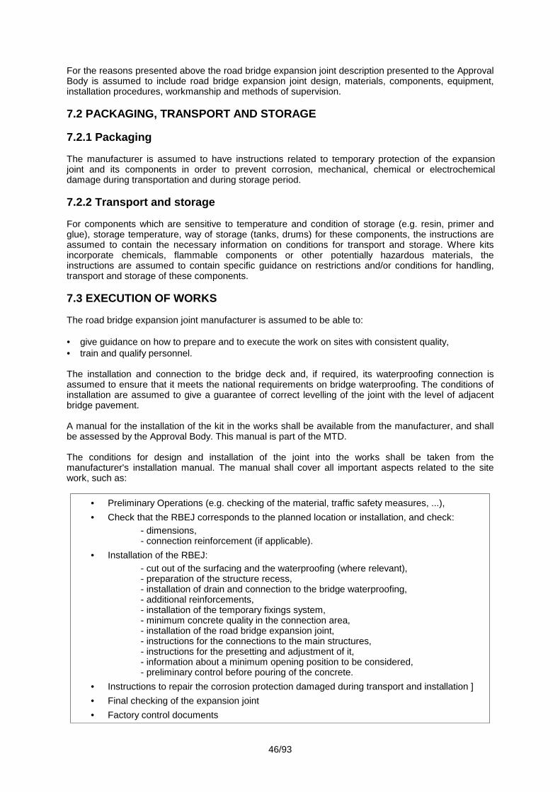
46/93
For the reasons presented above the road bridge expansion joint description presented to the ApprovalBody is assumed to include road bridge expansion joint design, materials, components, equipment,installation procedures, workmanship and methods of supervision.
7.2 PACKAGING, TRANSPORT AND STORAGE
7.2.1 Packaging
The manufacturer is assumed to have instructions related to temporary protection of the expansionjoint and its components in order to prevent corrosion, mechanical, chemical or electrochemicaldamage during transportation and during storage period.
7.2.2 Transport and storage
For components which are sensitive to temperature and condition of storage (e.g. resin, primer andglue), storage temperature, way of storage (tanks, drums) for these components, the instructions areassumed to contain the necessary information on conditions for transport and storage. Where kitsincorporate chemicals, flammable components or other potentially hazardous materials, theinstructions are assumed to contain specific guidance on restrictions and/or conditions for handling,transport and storage of these components.
7.3 EXECUTION OF WORKS
The road bridge expansion joint manufacturer is assumed to be able to:
give guidance on how to prepare and to execute the work on sites with consistent quality, train and qualify personnel.
The installation and connection to the bridge deck and, if required, its waterproofing connection isassumed to ensure that it meets the national requirements on bridge waterproofing. The conditions ofinstallation are assumed to give a guarantee of correct levelling of the joint with the level of adjacentbridge pavement.
A manual for the installation of the kit in the works shall be available from the manufacturer, and shallbe assessed by the Approval Body. This manual is part of the MTD.
The conditions for design and installation of the joint into the works shall be taken from themanufacturer's installation manual. The manual shall cover all important aspects related to the sitework, such as:
Preliminary Operations (e.g. checking of the material, traffic safety measures, ...), Check that the RBEJ corresponds to the planned location or installation, and check:
- dimensions,- connection reinforcement (if applicable).
Installation of the RBEJ:- cut out of the surfacing and the waterproofing (where relevant),- preparation of the structure recess,- installation of drain and connection to the bridge waterproofing,- additional reinforcements,- installation of the temporary fixings system,- minimum concrete quality in the connection area,- installation of the road bridge expansion joint,- instructions for the connections to the main structures,- instructions for the presetting and adjustment of it,- information about a minimum opening position to be considered,- preliminary control before pouring of the concrete.
Instructions to repair the corrosion protection damaged during transport and installation ] Final checking of the expansion joint Factory control documents

47/93
Where the kits involve the use of chemicals and other potentially hazardous materials, the installationmanual is assumed to give precise information on their safe disposal and packaging used to supplythem in accordance with national regulations, if applicable.
Where the kits incorporate flammable or hazardous components, the installation guide is assumed togive precise information to allow safe use and application.
For optimal self cleaning of gutter/seal, an adequate slope in the joint direction is assumed to beincluded as part of the bridge design, and recommended in the ETA.
7.4. MAINTENANCE AND REPAIR
Guidelines for periodic inspection, maintenance and repair, and specific measures related tomaintenance (e.g. replacement of components) shall be part of the Manufacturer's Technical Dossier.
It is assumed that regular maintenance is required to retain performance and to obtain the working lifeof the expansion joint. The type and frequency of such maintenance shall be specified, and shall bepart of the assessment of the kit.
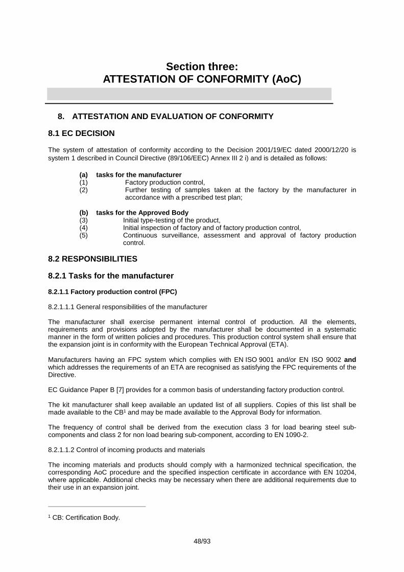
48/93
Section three:ATTESTATION OF CONFORMITY (AoC)
8. ATTESTATION AND EVALUATION OF CONFORMITY
8.1 EC DECISION
The system of attestation of conformity according to the Decision 2001/19/EC dated 2000/12/20 issystem 1 described in Council Directive (89/106/EEC) Annex III 2 i) and is detailed as follows:
(a) tasks for the manufacturer(1) Factory production control,(2) Further testing of samples taken at the factory by the manufacturer in
accordance with a prescribed test plan;
(b) tasks for the Approved Body(3) Initial type-testing of the product,(4) Initial inspection of factory and of factory production control,(5) Continuous surveillance, assessment and approval of factory production
control.
8.2 RESPONSIBILITIES
8.2.1 Tasks for the manufacturer
8.2.1.1 Factory production control (FPC)
8.2.1.1.1 General responsibilities of the manufacturer
The manufacturer shall exercise permanent internal control of production. All the elements,requirements and provisions adopted by the manufacturer shall be documented in a systematicmanner in the form of written policies and procedures. This production control system shall ensure thatthe expansion joint is in conformity with the European Technical Approval (ETA).
Manufacturers having an FPC system which complies with EN ISO 9001 and/or EN ISO 9002 andwhich addresses the requirements of an ETA are recognised as satisfying the FPC requirements of theDirective.
EC Guidance Paper B [7] provides for a common basis of understanding factory production control.
The kit manufacturer shall keep available an updated list of all suppliers. Copies of this list shall bemade available to the CB1 and may be made available to the Approval Body for information.
The frequency of control shall be derived from the execution class 3 for load bearing steel sub-components and class 2 for non load bearing sub-component, according to EN 1090-2.
8.2.1.1.2 Control of incoming products and materials
The incoming materials and products should comply with a harmonized technical specification, thecorresponding AoC procedure and the specified inspection certificate in accordance with EN 10204,where applicable. Additional checks may be necessary when there are additional requirements due totheir use in an expansion joint.
1 CB: Certification Body.

49/93
The incoming materials and products may also comply with other equivalent valid specificationsprovided that their use is compatible with the results of the approval tests. Then the specifications shallbe given in the ETA.
The manufacturer shall perform suitable incoming tests, specific instructions are given in family Parts.All products and materials shall be in accordance with the requirements of the ETA and thecorresponding specifications of the kit manufacturer.
8.2.1.1.3 Inspection and testing during production
The validity of the type and frequency of checks/tests conducted during production shall be consideredas a function of the production process. This will include the checks conducted during manufacture onproperties that cannot be inspected at a later stage and partly for checks on the final expansion joint.These may include:
definition of the number of samples taken by the kit manufacturer,
material properties e.g. tensile strength, hardness, surface finish or chemical composition,
determination of the dimensions of components,
checking correct assembly,
personnel qualification (e.g. welding, corrosion protection),
control measurements of the production process,
documentation of tests and test results.
All tests and control measurements shall be performed according to written procedures (test plan) withsuitable calibrated measuring devices. All test results shall be recorded in a consequent andsystematic way.
Both large and small companies produce these products and there is a wide variation in the materialsused and the production processes. Therefore a precise test plan can only be set up on a case-by-case basis.
Indirect methods are also sufficient, e.g. control of raw materials, manufacturing processes andproperties of components if the correlations to characteristics which are important for the performanceof the kit are given.
In the family Parts basic test plans (amount and type of tests and minimum frequencies) are given.This shall be the basis of specified test plan in the ETA2.
8.2.1.1.4 Control of non-conformity
The quality manual has to address control of non-conforming products.
8.2.1.1.5 Complaints
The quality manual shall include provisions to keep records of all complaints about the componentsand materials for at least five (5) years.
2 "According to frequency" and "sampling regime" could be based on experience or custom andpractice in a given product sector or statistical methods.

50/93
8.2.1.2 Testing of samples taken at the factory – Prescribed Test Plan
Further test of samples taken at the factory by the manufacturer may be conducted in accordance witha prescribed test plan, i.e. if not covered by the FPC system.
Both large and small companies produce these products and there is a wide variation in the materialsused. Therefore a precise prescribed test plan can only be set up on case-by-case basis. In the familyParts basic prescribed test plans (amount and type of tests and minimum frequencies) are given. Thisshall be the basis of the specified prescribed test plan in the ETA.
In general it is not necessary to conduct tests on kits (or assembled systems) but on the characteristicsand/or properties of components.
8.2.2 Tasks of the Approved Body
8.2.2.1 General
The CB may act with its own resources or subcontract inspection tasks and testing tasks to inspectionbodies and testing laboratories that meet the requirements of the Guidance Paper “A” [6].
The ITT and the assessment of the FPC based on initial inspection and continuous surveillance shallbe included in the control plan. The tasks and their frequency shall be given in the control plan and willdepend on the nature of the product. This is defined in the family Parts.
8.2.2.2 Initial Type-Testing
Approval tests will have been conducted by the Approval Body or under its responsibility (which mayinclude a proportion conducted by an indicated laboratory or by the manufacturer, witnessed by theApproval Body) in accordance with Chapter 5 of this ETAG. The Approval Body will have assessed theresults of these tests in accordance with Chapter 6 of this ETAG, as part of the ETA issuing procedure.
These test results should be used for the purposes of Initial Type-Testing.
If approval tests were made on prototypes or in case of changes in the production line or plant or ofcomponent(s), there may be a need for a new ITT (see also Chapter 9).
8.2.2.3 Assessment of the factory production control system. Initial inspection and continuoussurveillance
Assessment of the factory production control system is the responsibility of the Approved Body.
An assessment shall be carried out of each production unit to demonstrate that the factory productioncontrol is in conformity with the ETA and any supplementary information (control plan). Thisassessment shall be based on an initial inspection of the factory.
Subsequently continuous surveillance of factory production control is necessary to ensure continuingconformity with the ETA. Detailed instruction on the frequency of surveillance is given in the familyParts.
Surveillance inspections shall be conducted at least once a year.
8.2.2.4 Certification
The Approved Body shall issue a Certification of Conformity of the expansion joint.

51/93
8.3 DOCUMENTATION
The Approval Body issuing the ETA shall ensure that the manufacturer supplies the informationdetailed below. The information given below together with the requirements given in EC GuidancePaper B [7] will generally form the basis on which the factory production control (FPC) is assessed.
This information shall initially be prepared or collected by the Approval Body and shall be agreed withthe manufacturer. The following gives guidance on the type of information required:
(1) The ETA
See Section four of this Guideline.
Where the assessment of the joint depends in part on confidential information, such information shallbe included in the Manufacturer’s Technical Dossier. The ETA shall refer to this MTD. However, suchinformation shall not form part of the ETA.
(2) Basic manufacturing process
The basic manufacturing process shall be described in sufficient detail to support the proposed FPCmethods.
(3) Product and material specifications
These shall include, when necessary to assess the performance of the expansion joint:
detailed drawings (including manufacturing tolerances),
incoming (raw) materials specifications and declarations,
references to European and/or international standards or appropriate specifications,
manufacturer’s data sheets.
(4) Test plan (as part of FPC)
The manufacturer and the Approval Body issuing the ETA shall agree an FPC test plan.
An agreed FPC test plan is necessary as current specifications relating to quality managementsystems (Guidance Paper B, EN ISO 9001, etc.), do not ensure that the product specification remainsunchanged and they cannot address the technical validity of the type or frequency of checks/tests.
The validity of the type and frequency of checks/tests conducted during production and on the finalproduct shall be considered. This will include the checks conducted during manufacture on propertiesthat cannot be inspected at a later stage and checks on the final product. These will normally include afrequency of routine tests according to tables given in each family Part.
These tests need not necessarily be carried out in accordance with test methods described in theGuideline.
Where materials/components are not manufactured and tested by the supplier in accordance withagreed methods, then where appropriate they shall be subject to suitable checks/tests by themanufacturer before acceptance.
(5) Prescribed test plan
The manufacturer and the Approval Body issuing the ETA shall agree a prescribed test plan.
Cornerstones are given in family Parts.

52/93
8.4 CE MARKING AND ACCOMPANYING INFORMATION
According to Council Directive 93/68/EEC the CE Marking consists of the letters “CE” followed by theidentification number of the notified certification body.
The ETA shall indicate the information to accompany the CE marking.
In accordance with Guidance Paper D the required information to accompany the symbol “CE” is:
name/address or identifying mark of the producer,
last two digits of the year in which the CE marking was affixed,
number of the EC certificate of conformity,
number of the ETA,
reference to the concerned Part of this ETA Guideline.
nnnn (1)
XXXX (2)12 (3)
nnnn-CPD-zzzz (4)ETA-08/0007 (5)
ETAG No 032:2012 (6) Part Y
(1) Identification number of the notified body involved in the attestation of conformity (certificationbody),
(2) Name/address or the identifying mark of the producer,(3) Last two digits of the year in which the CE marking was affixed,(4) Number of the EC certificate of conformity (consisting of number of notified body involved in the
AoC (“nnnn”) – CPD – number of EC certificate of conformity (“zzzz”)),(5) Number of the European Technical Approval,(6) ETAG number including date of publication.
The CE marking shall be affixed according to Guidance Paper D, 3.2.
The following accompanying information on the product separate to the CE marking shall be given bythe manufacturer:
- date of manufacture,
- identification number of the product.
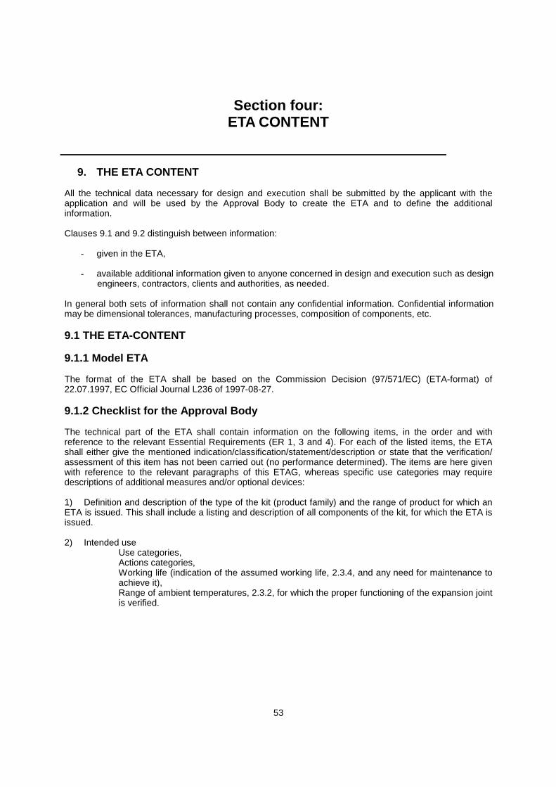
53
Section four:ETA CONTENT
9. THE ETA CONTENT
All the technical data necessary for design and execution shall be submitted by the applicant with theapplication and will be used by the Approval Body to create the ETA and to define the additionalinformation.
Clauses 9.1 and 9.2 distinguish between information:
- given in the ETA,
- available additional information given to anyone concerned in design and execution such as designengineers, contractors, clients and authorities, as needed.
In general both sets of information shall not contain any confidential information. Confidential informationmay be dimensional tolerances, manufacturing processes, composition of components, etc.
9.1 THE ETA-CONTENT
9.1.1 Model ETA
The format of the ETA shall be based on the Commission Decision (97/571/EC) (ETA-format) of22.07.1997, EC Official Journal L236 of 1997-08-27.
9.1.2 Checklist for the Approval Body
The technical part of the ETA shall contain information on the following items, in the order and withreference to the relevant Essential Requirements (ER 1, 3 and 4). For each of the listed items, the ETAshall either give the mentioned indication/classification/statement/description or state that the verification/assessment of this item has not been carried out (no performance determined). The items are here givenwith reference to the relevant paragraphs of this ETAG, whereas specific use categories may requiredescriptions of additional measures and/or optional devices:
1) Definition and description of the type of the kit (product family) and the range of product for which anETA is issued. This shall include a listing and description of all components of the kit, for which the ETA isissued.
2) Intended useUse categories,Actions categories,Working life (indication of the assumed working life, 2.3.4, and any need for maintenance toachieve it),Range of ambient temperatures, 2.3.2, for which the proper functioning of the expansion jointis verified.
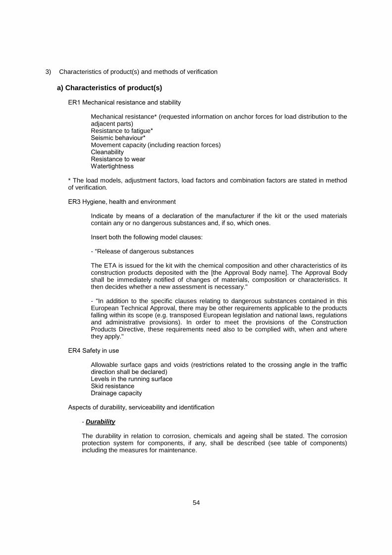
54
3) Characteristics of product(s) and methods of verification
a) Characteristics of product(s)
ER1 Mechanical resistance and stability
Mechanical resistance* (requested information on anchor forces for load distribution to theadjacent parts)Resistance to fatigue*Seismic behaviour*Movement capacity (including reaction forces)CleanabilityResistance to wearWatertightness
* The load models, adjustment factors, load factors and combination factors are stated in methodof verification.
ER3 Hygiene, health and environment
Indicate by means of a declaration of the manufacturer if the kit or the used materialscontain any or no dangerous substances and, if so, which ones.
Insert both the following model clauses:
- "Release of dangerous substances
The ETA is issued for the kit with the chemical composition and other characteristics of itsconstruction products deposited with the [the Approval Body name]. The Approval Bodyshall be immediately notified of changes of materials, composition or characteristics. Itthen decides whether a new assessment is necessary."
- "In addition to the specific clauses relating to dangerous substances contained in thisEuropean Technical Approval, there may be other requirements applicable to the productsfalling within its scope (e.g. transposed European legislation and national laws, regulationsand administrative provisions). In order to meet the provisions of the ConstructionProducts Directive, these requirements need also to be complied with, when and wherethey apply."
ER4 Safety in use
Allowable surface gaps and voids (restrictions related to the crossing angle in the trafficdirection shall be declared)Levels in the running surfaceSkid resistanceDrainage capacity
Aspects of durability, serviceability and identification
- Durability
The durability in relation to corrosion, chemicals and ageing shall be stated. The corrosionprotection system for components, if any, shall be described (see table of components)including the measures for maintenance.
55
- Serviceability
The assessment (where required by this ETAG and/or where declared by the manufacturer)on the effects on the performance of the product due to the declared limits of site conditionsduring installation shall be stated.
- Identification
Insert the following paragraph: “The ETA is issued for the product/kit on the basis ofagreed data/information, deposited with {the Approval Body name}, which identifies theproduct/kit that has been assessed and judged. Changes to the product/productionprocess/kit, which could result in this deposited data/information being incorrect, shall benotified to the {the Approval Body name} before the changes are introduced. The {Approvalbody name} will decide whether or not such changes affect the ETA and consequently thevalidity of the CE marking on the basis of the ETA and if so whether furtherassessment/alterations to the ETA, shall be necessary.”
For components, insert the following paragraph: "The kit comprises components which are factory-made by the ETA-holder and/or the component suppliers. The ETA-holder is ultimately responsiblefor the kit."
List all components and address the following aspects:- Designation of each component- Materials by referring to standards (with relevant certificate, if needed), trade names,
specific requirements, as relevant- Description and drawings for all components. Dimensions as required especially for
identification of the component, design of the works, especially critical dimensionsrelevant to the installation of the system, minimum length of thread engagement, etc.as relevant
- Etc. as relevant
b) Methods of verification
Insert the following paragraph: "The assessment of the fitness of the product/kit for the intendeduse has been made in compliance with the Guideline for European Technical Approval of“Expansion joints for road bridges”, ETAG 032, Part 1: “General”, in conjunction with ETAG 032,Part Y."
For mechanical resistance, resistance to fatigue and seismic behaviour the followingprinciples shall be addressed:
- The load models used (LM1EJ, FLM1EJ or FLM2EJ of the general Part of this ETAG),- Adjustment factors (),- Load factors (),- and Combination factors ().
For components, verification results shall be presented in a table.
4) Evaluation of Conformity and CE marking
- The Attestation of conformity system, referred to Chapter 8, 8.1.- Responsibilities
56
Tasks of the manufacturer
Factory production control
Indicate the FPC control plan (including the aspects for components) with type and minimumfrequency of tests.
Testing of samples taken at the factory
Insert type and minimum frequency of tests where relevant.
Other tasks of manufacturer
Insert the following paragraph:
"The manufacturer of the product makes available concerned additional confidential informationto the certification body for the evaluation."
Tasks of Approved Bodies
Initial type-testing of the product
Insert the following paragraph: "For ITT, the results of the tests performed as part of theassessment for the ETA may be used unless there are changes in the product, production lineor plant, where these changes have the effect of invalidating the results of one or more of theapproval tests. In such cases the necessity for new approval tests and/or ITT has to be agreedbetween the {Approval Body and Certification body name}, and the manufacturer involved."
Initial inspection of factory and factory production control
Insert the following paragraph: “The Approved Body shall ascertain that in accordance with theprescribed test plan, the precautions in the factory, in particular the staff and the equipmentconcerning, and the FPC are suitable to ensure a continuous and orderly manufacturing of thekit/product with the specifications mentioned in the relevant sections.”
Continuous surveillance, assessment and approval of factory production controlInsert the following paragraph: “The Approved Body shall visit the factory at least one (1) timeper year for surveillance. It shall be verified that the system of FPC and the specifiedmanufacturing process are maintained taking into account the prescribed control plan.”
The results of product certification and continuous surveillance shall be made available ondemand by the Approved Body to the {Approval Body name}.
In cases where the provisions of the ETA and the prescribed control plan are no longer fulfilledthe certificate of conformity shall be withdrawn and the {Approval Body name} shall be informedimmediately.
9.2 ADDITIONAL INFORMATION
It shall be stated in the ETA, that the ETA holder is responsible to inform anyone concerned about the useof the RBEJ system. Additional information shall be held available at the ETA holder and shall bedistributed as needed.
The ETA shall also include other information related to movement capacity (e.g. maximum gap or overlapof fingers) where relevant to the design of the joint and/or where required by national regulations.

57
It shall be stated in the ETA, that additional (possibly confidential) information shall be supplied to theCertification Body for the evaluation of conformity, see 8.3(1) of this ETAG.
9.3 CONFIDENTIAL INFORMATION
Copies of manufacturing drawings, specifications and installation manual of the RBEJ system andcomponents in sufficient detail to define manufacturing (e.g. chemical composition of materials not definedin standards) need to be deposited at the Approval Body and Certification Body. These documents arerestricted or confidential and proprietary and shall not be given to other parties without authorisation fromthe manufacturer.
The ETA shall contain, taking into account the need of confidentiality, sufficient detailed information as toidentify without ambiguity the product in case of complaints or accidents.
When such information/references are of a confidential nature it/they shall exist on the ETA file managedby the Approval Body and as necessary on the relevant file of the notified product certification bodyinvolved.
This/these information/references shall also be of assistance in any renewal of the ETA.
The type, scale, range of information will be based on the identification clauses in Chapter 5 of the ETAG.
9.4 INSTALLATION REQUIREMENTS
Additional installation aspects other than those listed in 9.1 may need to be provided:
- Use with skew bridges,- Connecting with the waterproofing system of the bridge,- Anchorage with the structure of the bridge,- Etc. (e.g. correct levelling of the adjacent parts) as relevant.
This chapter sets out assumptions and recommendations for packaging, transport and storage,installation, maintenance and repair under which the assessment of the fitness for use according to theGuideline can be made.
"Successful application of a road bridge expansion joint is only obtained when the approved expansionjoint are installed by competent personnel."3
The installation manual forms part of the ETA and it shall be available to the installer.
Note for users and owners: noise generation on a joint is a point which may be verified in the designand the construction of the works.
3 Clause coming from the 2nd part of 7.0.
58
ANNEXES TO THE ETAG
Annex A: Common terminology (to be taken over in every ETAG).
Annex B: Assumption of working life of construction products (EOTA Guidance document 002).
Annex C: Assessment of the working life of products (EOTA Guidance document 003).
Annex D: The provision of data for assessment leading to ETA (EOTA Guidance Document 004).
Annex E: Editorial aspects of ETAGs (EOTA Guidance Document 005).
Annex F: Reference material for ETAGs, Comprehension Documents for ETAGs, Updating process ofETAGs.
Annex G: Traffic loads and combinations.
Annex H: Number of products to be tested.
Annex J: Seismic approach – design philosophy for RBEJ.
Annex K: Movement capacity test method.
Annex L: Watertightness test method.
59
Annex ACOMMON TERMINOLOGY
(definitions, clarifications, abbreviations)See Document “Common Terms used in Guidelines for ETAs” available on the EOTA websitewww.eota.be, Section “Endorsed ETAGs”.
Annex BASSUMPTION OF WORKING LIFE OF CONSTRUCTION
PRODUCTS (EOTA GUIDANCE DOCUMENT 002)
Annex CASSESSMENT OF THE WORKING LIFE OF PRODUCTS (EOTA
GUIDANCE DOCUMENT 003)
Annex DTHE PROVISION OF DATA FOR ASSESSMENT LEADING TO
ETA (EOTA GUIDANCE DOCUMENT 004)
Annex EEDITORIAL ASPECTS OF ETAGS (EOTA GUIDANCE
DOCUMENT 005)
Annex FREFERENCE MATERIAL FOR ETAGS, COMPREHENSION
DOCUMENTS FOR ETAGS, UPDATING PROCESS OF ETAGS
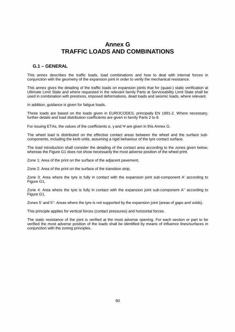
60
Annex GTRAFFIC LOADS AND COMBINATIONS
G.1 – GENERAL
This annex describes the traffic loads, load combinations and how to deal with internal forces inconjunction with the geometry of the expansion joint in order to verify the mechanical resistance.
This annex gives the detailing of the traffic loads on expansion joints that for (quasi-) static verification atUltimate Limit State and where requested in the relevant family Parts at Serviceability Limit State shall beused in combination with prestress, imposed deformations, dead loads and seismic loads, where relevant.
In addition, guidance is given for fatigue loads.
These loads are based on the loads given in EUROCODES, principally EN 1991-2. Where necessary,further details and load distribution coefficients are given in family Parts 2 to 8.
For issuing ETAs, the values of the coefficients , and are given in this Annex G.
The wheel load is distributed on the effective contact areas between the wheel and the surface sub-components, including the kerb units, assuming a rigid behaviour of the tyre contact surface.
The load introduction shall consider the detailing of the contact area according to the zones given below,whereas the Figure G1 does not show necessarily the most adverse position of the wheel print.
Zone 1: Area of the print on the surface of the adjacent pavement,
Zone 2: Area of the print on the surface of the transition strip,
Zone 3: Area where the tyre is fully in contact with the expansion joint sub-component A’ according toFigure G1,
Zone 4: Area where the tyre is fully in contact with the expansion joint sub-component A’’ according toFigure G1,
Zones 5’ and 5’’: Areas where the tyre is not supported by the expansion joint (areas of gaps and voids).
This principle applies for vertical forces (contact pressures) and horizontal forces.
The static resistance of the joint is verified at the most adverse opening. For each section or part to beverified the most adverse position of the loads shall be identified by means of influence lines/surfaces inconjunction with the zoning principles.
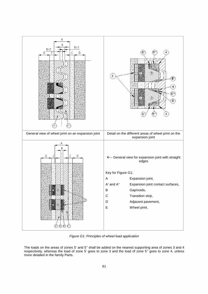
61
General view of wheel print on an expansion joint Detail on the different areas of wheel print on theexpansion joint
-- General view for expansion joint with straightedges
Key for Figure G1:
A Expansion joint,
A’ and A’’ Expansion joint contact surfaces,
B Gap/voids,
C Transition strip,
D Adjacent pavement,
E Wheel print.
Figure G1: Principles of wheel load application
The loads on the areas of zones 5’ and 5’’ shall be added on the nearest supporting area of zones 3 and 4respectively, whereas the load of zone 5’ goes to zone 3 and the load of zone 5’’ goes to zone 4, unlessmore detailed in the family Parts.
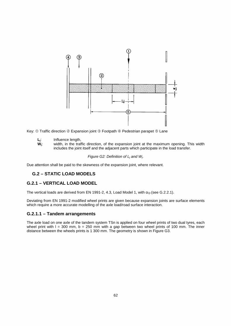
62
Key: Traffic direction Expansion joint Footpath Pedestrian parapet Lane
Lj: Influence length,Wj: width, in the traffic direction, of the expansion joint at the maximum opening. This width
includes the joint itself and the adjacent parts which participate in the load transfer.
Figure G2: Definition of Lj and Wj.
Due attention shall be paid to the skewness of the expansion joint, where relevant.
G.2 – STATIC LOAD MODELS
G.2.1 – VERTICAL LOAD MODEL
The vertical loads are derived from EN 1991-2, 4.3, Load Model 1, with Qi (see G.2.2.1).
Deviating from EN 1991-2 modified wheel prints are given because expansion joints are surface elementswhich require a more accurate modelling of the axle load/road surface interaction.
G.2.1.1 – Tandem arrangements
The axle load on one axle of the tandem system TSn is applied on four wheel prints of two dual tyres, eachwheel print with l = 300 mm, b = 250 mm with a gap between two wheel prints of 100 mm. The innerdistance between the wheels prints is 1 300 mm. The geometry is shown in Figure G3.
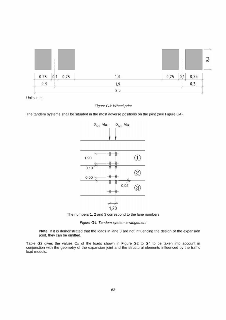
63
Units in m.
Figure G3: Wheel print
The tandem systems shall be situated in the most adverse positions on the joint (see Figure G4).
The numbers 1, 2 and 3 correspond to the lane numbers
Figure G4: Tandem system arrangement
Note: If it is demonstrated that the loads in lane 3 are not influencing the design of the expansionjoint, they can be omitted.
Table G2 gives the values Qik of the loads shown in Figure G2 to G4 to be taken into account inconjunction with the geometry of the expansion joint and the structural elements influenced by the trafficload models.

64
G.2.1.2 – Load Model 1
Only tandem systems TS apply, not the uniformly distributed loads (UDL) as they are not relevant for theexpansion joints.
Table G1: Basic values
Location Tandem system Axle loads Qik (kN)Lane number 1 TS1 300
Lane number 2 TS2 200
Lane number 3 TS3 100
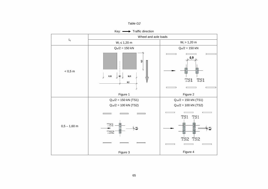
65
Table G2
Key: Traffic direction
LjWheel and axle loads
W j 1,20 m W j > 1,20 m
< 0,5 m
Qik/2 = 150 kN
Figure 1
Qik/2 = 150 kN
Figure 2
0,5 – 1,60 m
Q1k/2 = 150 kN (TS1)
Q2k/2 = 100 kN (TS2)
Figure 3
Q1k/2 = 150 kN (TS1)
Q2k/2 = 100 kN (TS2)
Figure 4
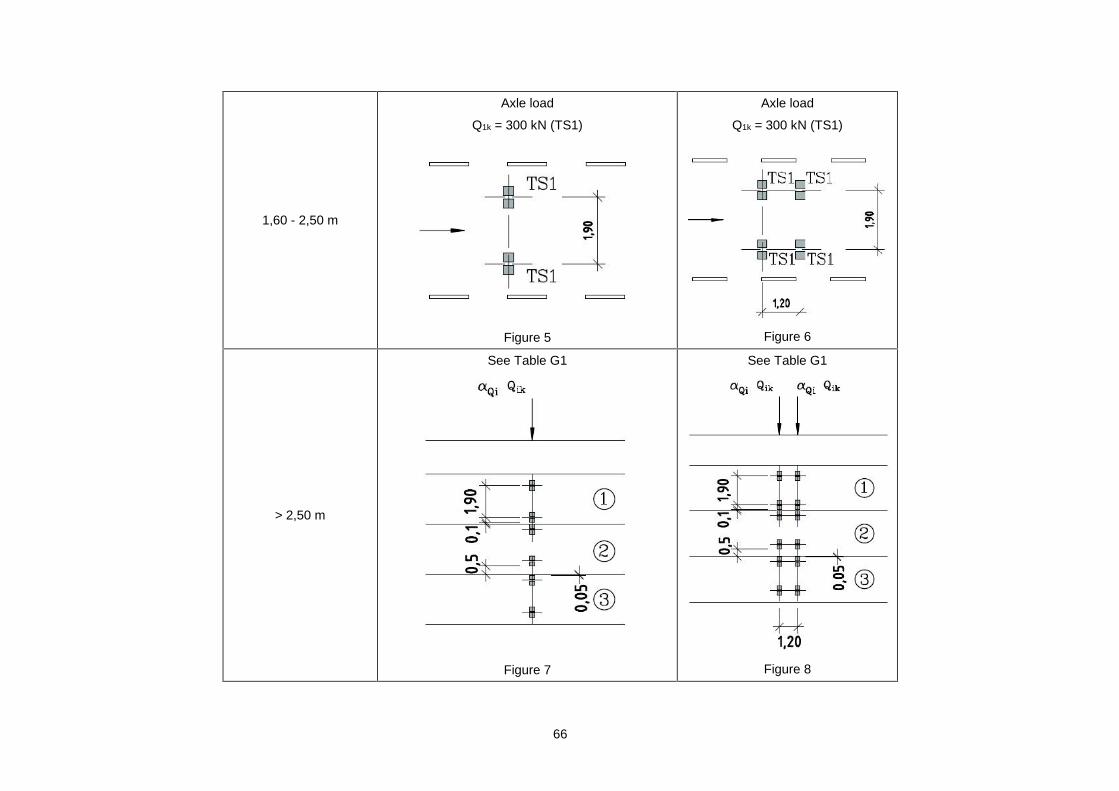
66
1,60 - 2,50 m
Axle load
Q1k = 300 kN (TS1)
Figure 5
Axle load
Q1k = 300 kN (TS1)
Figure 6
> 2,50 m
See Table G1
Figure 7
See Table G1
Figure 8
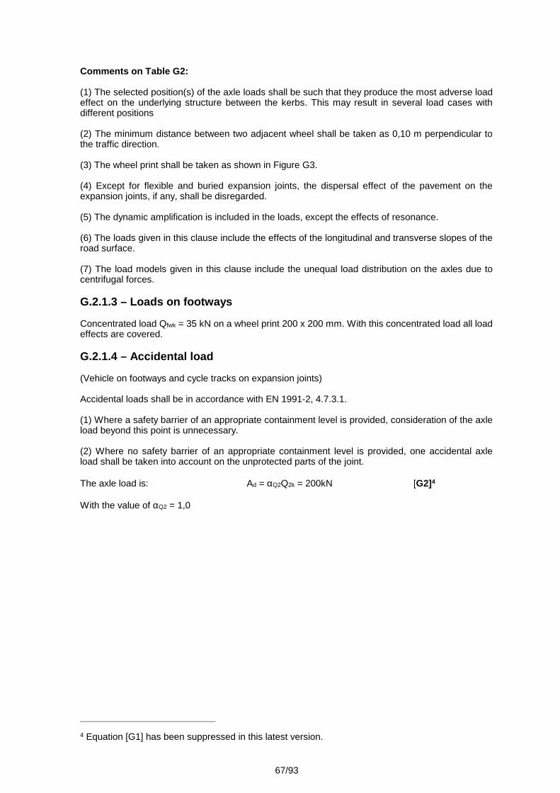
67/93
Comments on Table G2:
(1) The selected position(s) of the axle loads shall be such that they produce the most adverse loadeffect on the underlying structure between the kerbs. This may result in several load cases withdifferent positions
(2) The minimum distance between two adjacent wheel shall be taken as 0,10 m perpendicular tothe traffic direction.
(3) The wheel print shall be taken as shown in Figure G3.
(4) Except for flexible and buried expansion joints, the dispersal effect of the pavement on theexpansion joints, if any, shall be disregarded.
(5) The dynamic amplification is included in the loads, except the effects of resonance.
(6) The loads given in this clause include the effects of the longitudinal and transverse slopes of theroad surface.
(7) The load models given in this clause include the unequal load distribution on the axles due tocentrifugal forces.
G.2.1.3 – Loads on footways
Concentrated load Qfwk = 35 kN on a wheel print 200 x 200 mm. With this concentrated load all loadeffects are covered.
G.2.1.4 – Accidental load
(Vehicle on footways and cycle tracks on expansion joints)
Accidental loads shall be in accordance with EN 1991-2, 4.7.3.1.
(1) Where a safety barrier of an appropriate containment level is provided, consideration of the axleload beyond this point is unnecessary.
(2) Where no safety barrier of an appropriate containment level is provided, one accidental axleload shall be taken into account on the unprotected parts of the joint.
The axle load is: Ad = Q2Q2k = 200kN [G2]4
With the value of Q2 = 1,0
4 Equation [G1] has been suppressed in this latest version.
68/93
Key: Pedestrian parapet Safety barrier Expansion joint F = Ad/2 = 100 kN
Figure G5: Accidental loads on footway
G.2.2 – HORIZONTAL LOAD MODEL
For expansion joints, the horizontal loads are derived from Load Model 1 given in EN 1991-2.
Only tandem systems TS apply, not the uniformly distributed loads UDL as they are not relevant forthe expansion joints.
Depending on the width of the expansion joint one axle of a tandem shall be considered when Wj issmaller than or equal to 1,20 m or two axles when W j is greater than 1,20 m.
G.2.2.1 – Braking and acceleration forces
Braking and acceleration forces are assumed to act in the traffic direction and are derived fromLoad Model 1, TS1 only.
The braking force applied by one axle on an sub-component of the expansion joint shall becalculated with:
Qlk = bk x Q1 x Q1k = 120 kN [G3]
The value for Q1 is 1,0 and
bk = 0,4, the characteristic value of the relationship between Qlk / Q1k for the deceleration effect.
1) Where relevant, the influence of the second axle of TS1 shall be considered.2) If there are no other requirements in the family Parts, the braking force from a wheel may
be distributed on the load carrying sub-components equivalent to the summarized contactstresses, as follows after the subtraction of voids and spaces (see Figure G1). As a result,the horizontal forces may be the forces caused by one wheel or a part of it.
3) Braking forces that deviate from the traffic direction do not have to be consideredseparately as they are covered under G.2.2.2 centrifugal forces.
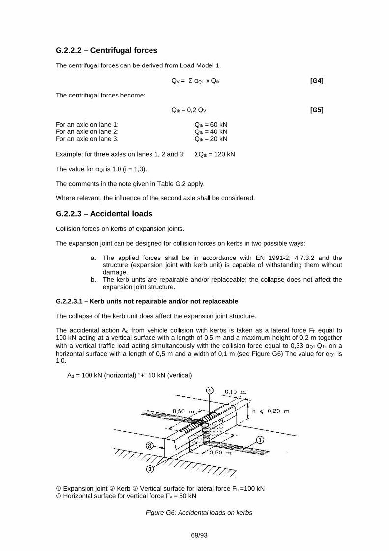
69/93
G.2.2.2 – Centrifugal forces
The centrifugal forces can be derived from Load Model 1.
QV = Qi x Qik [G4]
The centrifugal forces become:
Qtk = 0,2 QV [G5]
For an axle on lane 1: Qtk = 60 kNFor an axle on lane 2: Qtk = 40 kNFor an axle on lane 3: Qtk = 20 kN
Example: for three axles on lanes 1, 2 and 3: Qtk = 120 kN
The value for Qi is 1,0 (i = 1,3).
The comments in the note given in Table G.2 apply.
Where relevant, the influence of the second axle shall be considered.
G.2.2.3 – Accidental loads
Collision forces on kerbs of expansion joints.
The expansion joint can be designed for collision forces on kerbs in two possible ways:
a. The applied forces shall be in accordance with EN 1991-2, 4.7.3.2 and thestructure (expansion joint with kerb unit) is capable of withstanding them withoutdamage.
b. The kerb units are repairable and/or replaceable; the collapse does not affect theexpansion joint structure.
G.2.2.3.1 – Kerb units not repairable and/or not replaceable
The collapse of the kerb unit does affect the expansion joint structure.
The accidental action Ad from vehicle collision with kerbs is taken as a lateral force Fh equal to100 kN acting at a vertical surface with a length of 0,5 m and a maximum height of 0,2 m togetherwith a vertical traffic load acting simultaneously with the collision force equal to 0,33 Q1 Q1k on ahorizontal surface with a length of 0,5 m and a width of 0,1 m (see Figure G6) The value for Q1 is1,0.
Ad = 100 kN (horizontal) “+” 50 kN (vertical)
Expansion joint Kerb Vertical surface for lateral force Fh =100 kN Horizontal surface for vertical force Fv = 50 kN
Figure G6: Accidental loads on kerbs
70/93
G.2.2.3.2 – Kerb units repairable and/or replaceable
The collapse of the kerb unit does not affect the expansion joint structure.
A horizontal load of 10 kN shall be applied on the kerb. No vertical loads are to be applied. The loadintroduction is the same as to G.2.2.3.1.
An example of these replaceable and/or repairable kerb units is: cover plate.
Ad = 10 kN (horizontal)
G.3 – FATIGUE LOAD MODELS
G.3.1 – GENERAL
The Fatigue Load Model 1 (FLM1EJ) and the fatigue Load Model 2 (FLM2EJ) given hereafter arebased respectively on FLM1 and FLM4 of EN 1991-2.
Deviating from EN 1991-2 modified wheel prints are given because expansion joints are surfaceelements which require a more accurate modelling of the axle load/road surface interaction.
The actions, derived from the fatigue load models, which affect the fatigue behaviour, can bevertical, horizontal or a combination of both. The load models in EN 1991-2 include dynamic loadamplification appropriate for pavements of good quality, which is also relevant for expansion joints.
The unevenness and the resonance at the expansion joint may result in an additional dynamicfactor fat for vertical loads. For horizontal loads, an additional dynamic factor fat,h, different fromthe vertical may exist. Upswing after loading (free vibration) shall be considered where relevant. Inthe family Part more detailed approaches are given, where relevant.
Since there is no interference between effects of successive axle loads, the load models forexpansion joints are defined with respect to axle loads only (not vehicles).
For the fatigue assessment of expansion joints FLM1EJ applies. FLM1EJ is intended to be used tocheck whether the fatigue life may be considered as unlimited.
As an alternative, FLM2EJ, which is a set of equivalent axles, can be chosen by the manufacturer.
71/93
Table G3: Axle types, wheel prints and axle geometries
Fatigueload model
Axletype
Wheel print Aw(l x b) Wheel print axle geometry in transverse direction
FLM1EJ 300 x 250Wheel print 250 mm, gap 100 mm, wheel print 250 mm,distance 1300 mm, wheel print 250, gap 100 mm, wheel print250 mm.
FLM2EJ
A 300 x 250 Wheel print 250 mm, distance 2 000 mm, wheel print 250 mm.
B 300 x 250 See FLM1EJ.
C 300 x 333Wheel print 333 mm, distance 1 834 mm, wheel print 333 mm.
As an alternative, for sub-components which are not subjectedto the total wheel/axle load, axle C can be replaced by axle A.
For the use of this model, the number of vehicles can be selected from EN 1991-2, Table 4.5 andthe transverse distribution is given in EN 1991-2, Figure 4.6.
The vertical axle load histogram in Table G3 is derived from EN 1991-2, Table 4.7 for the Traffictype Medium Distance. The number of vertical axle loads per year is found by multiplying thenumber of vehicles per year from EN 1991-2, Table 4.5 with the axle number rates.
G.3.2 – FATIGUE LOAD MODEL 1 (FLM1EJ)
The interaction of the vertical and the horizontal force applied by one axle for slopes in the trafficdirection not exceeding 4 % shall be calculated with:
Q1k,fat = fat x Q1k x 0,7= 273 kN [G.6]
fat = 1,3 and Q1k = 300 kN
together with:
Q1lk,fat = 0,2 x fat,h x Q1k x 0,7= 42 kN [G.7]
in traffic direction
fat,h = 1,0
For slopes exceeding 4 % the following applies:
Q1lk,fat = (7,0x + 14,0) kN
x = slope in %
72/93
G.3.3 – FATIGUE LOAD MODEL 2 (FLM2EJ)
For the use of this model, the number of vehicles can be selected from EN 1991-2, Table 4.5 andthe transverse distribution is given in Figure 4.6.
The interaction of vertical and horizontal axle load for slopes in the traffic direction is given inTable G4.
Table G4: Vertical and horizontal loads for fatigue
Q1k,fat
Vertical axle load kNIncluding Δφfat = 1,3
Q1lk,fat
Horizontal axle load kNin traffic direction
Including fat,h = 1,0
Axle number rate Axle type
100 - 1,10 A
120 - 1,25 C
150 y = 3x + 8 0,20 B
170 y = 4,5x + 6 0,45 B
190 y = 5x + 8 0,45 B
In which x = slope in % with a minimum value of 4.
The loads mentioned in Table G4, include the following additional dynamic factors fat = 1,3 andfat,h = 1,0. These factors can be modified based on over-rolling tests and/or analyses as indicatedin 5.1.1.3.
G.4 – VERIFICATION
G.4.1 – GENERAL
The verifications at the Ultimate Limit State are carried out for full plastic behaviour, taking intoaccount the verification methods given in the relevant European Standards.
The verifications at the serviceability limit state (SLS) evaluate the capability of the expansion jointand its geometry to deal with internal deformations due to the applied loads and with the imposeddisplacements from the main structure under normal conditions, but also under accidental loadsand seismic imposed movements.
In the equations below, the sign “+” means: “In combination with”.
In expansion joints the horizontal loads cannot occur independent of vertical loads. The factor 0covers the effect from loads arising from the same source.
G.4.2 – COMBINATIONS AT THE ULTIMATE LIMIT STATE
The concurrence of traffic loads and opening positions of the joint is combined within differentdesign situations using combination factors 0T, 0d, 0lk, 0tk.
The vertical traffic loads in combinations are derived from Load Model 1.
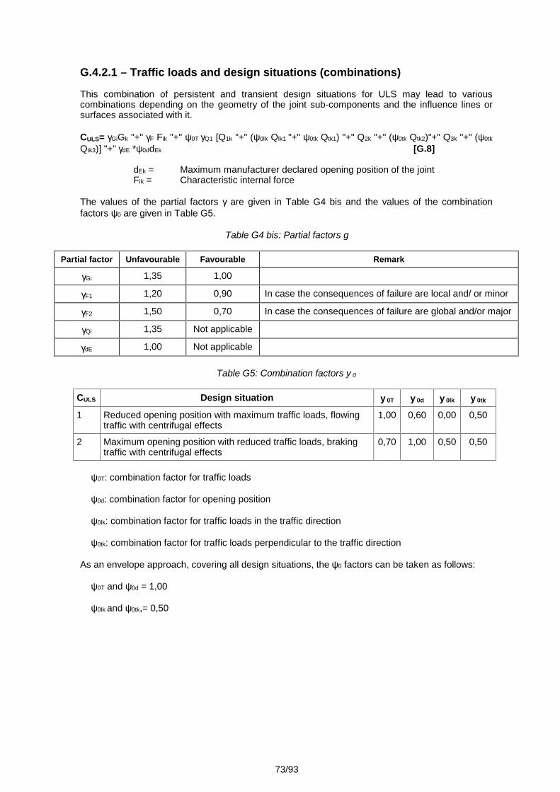
73/93
G.4.2.1 – Traffic loads and design situations (combinations)
This combination of persistent and transient design situations for ULS may lead to variouscombinations depending on the geometry of the joint sub-components and the influence lines orsurfaces associated with it.
CULS= GiGk "+" F Fik "+" 0T Q1 [Q1k "+" (0lk Qlk1 "+" 0tk Qtk1) "+" Q2k "+" (0tk Qtk2)"+" Q3k "+" (0tk
Qtk3)] "+" dE *0ddEk [G.8]
dEk = Maximum manufacturer declared opening position of the jointFik = Characteristic internal force
The values of the partial factors are given in Table G4 bis and the values of the combinationfactors 0 are given in Table G5.
Table G4 bis: Partial factors
Partial factor Unfavourable Favourable Remark
Gi 1,35 1,00
F1 1,20 0,90 In case the consequences of failure are local and/ or minor
F2 1,50 0,70 In case the consequences of failure are global and/or major
Qi 1,35 Not applicable
dE 1,00 Not applicable
Table G5: Combination factors 0
CULS Design situation 0T 0d 0lk 0tk
1 Reduced opening position with maximum traffic loads, flowingtraffic with centrifugal effects
1,00 0,60 0,00 0,50
2 Maximum opening position with reduced traffic loads, brakingtraffic with centrifugal effects
0,70 1,00 0,50 0,50
0T: combination factor for traffic loads
0d: combination factor for opening position
0lk: combination factor for traffic loads in the traffic direction
0tk: combination factor for traffic loads perpendicular to the traffic direction
As an envelope approach, covering all design situations, the 0 factors can be taken as follows:
0T and 0d = 1,00
0lk and 0tk,= 0,50
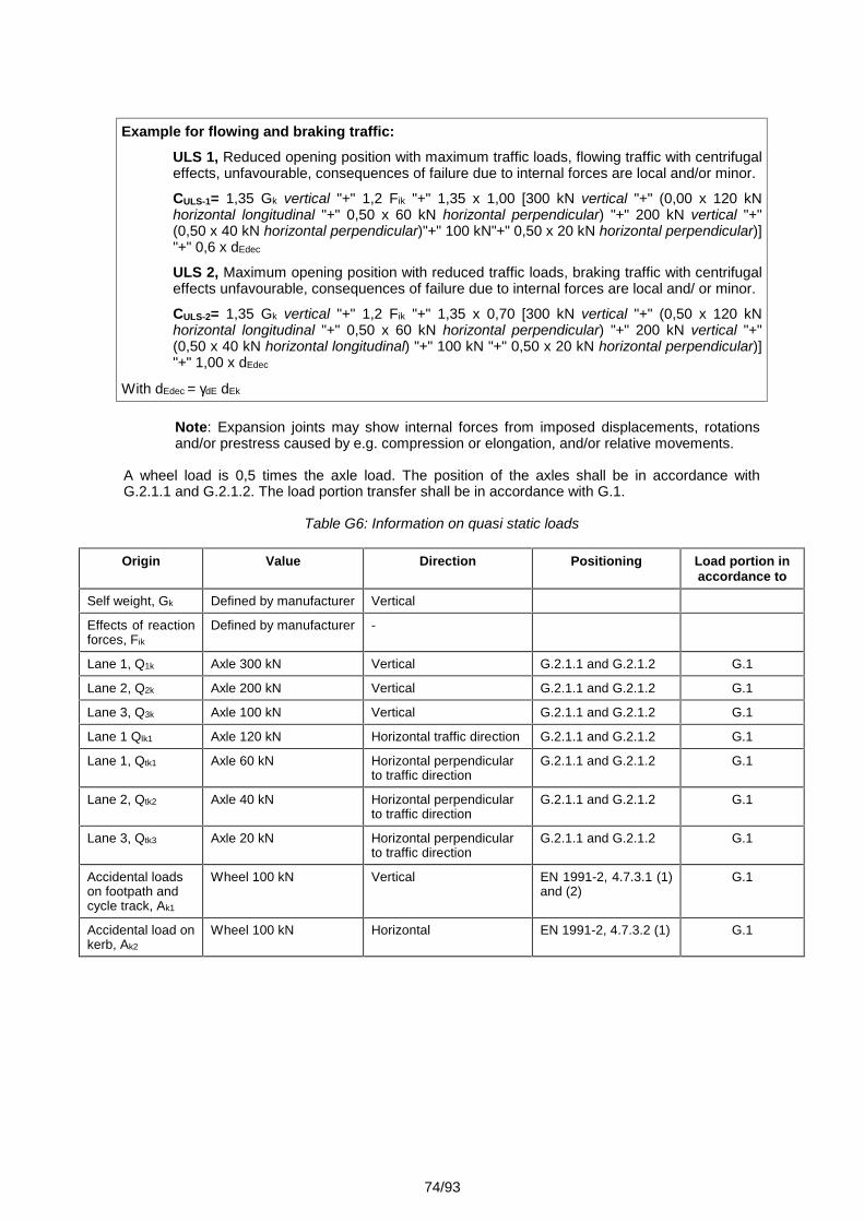
74/93
Example for flowing and braking traffic:ULS 1, Reduced opening position with maximum traffic loads, flowing traffic with centrifugaleffects, unfavourable, consequences of failure due to internal forces are local and/or minor.
CULS-1= 1,35 Gk vertical "+" 1,2 Fik "+" 1,35 x 1,00 [300 kN vertical "+" (0,00 x 120 kNhorizontal longitudinal "+" 0,50 x 60 kN horizontal perpendicular) "+" 200 kN vertical "+"(0,50 x 40 kN horizontal perpendicular)"+" 100 kN"+" 0,50 x 20 kN horizontal perpendicular)]"+" 0,6 x dEdec
ULS 2, Maximum opening position with reduced traffic loads, braking traffic with centrifugaleffects unfavourable, consequences of failure due to internal forces are local and/ or minor.
CULS-2= 1,35 Gk vertical "+" 1,2 Fik "+" 1,35 x 0,70 [300 kN vertical "+" (0,50 x 120 kNhorizontal longitudinal "+" 0,50 x 60 kN horizontal perpendicular) "+" 200 kN vertical "+"(0,50 x 40 kN horizontal longitudinal) "+" 100 kN "+" 0,50 x 20 kN horizontal perpendicular)]"+" 1,00 x dEdec
With dEdec = dE dEk
Note: Expansion joints may show internal forces from imposed displacements, rotationsand/or prestress caused by e.g. compression or elongation, and/or relative movements.
A wheel load is 0,5 times the axle load. The position of the axles shall be in accordance withG.2.1.1 and G.2.1.2. The load portion transfer shall be in accordance with G.1.
Table G6: Information on quasi static loads
Origin Value Direction Positioning Load portion inaccordance to
Self weight, Gk Defined by manufacturer Vertical
Effects of reactionforces, Fik
Defined by manufacturer -
Lane 1, Q1k Axle 300 kN Vertical G.2.1.1 and G.2.1.2 G.1
Lane 2, Q2k Axle 200 kN Vertical G.2.1.1 and G.2.1.2 G.1
Lane 3, Q3k Axle 100 kN Vertical G.2.1.1 and G.2.1.2 G.1
Lane 1 Qlk1 Axle 120 kN Horizontal traffic direction G.2.1.1 and G.2.1.2 G.1
Lane 1, Qtk1 Axle 60 kN Horizontal perpendicularto traffic direction
G.2.1.1 and G.2.1.2 G.1
Lane 2, Qtk2 Axle 40 kN Horizontal perpendicularto traffic direction
G.2.1.1 and G.2.1.2 G.1
Lane 3, Qtk3 Axle 20 kN Horizontal perpendicularto traffic direction
G.2.1.1 and G.2.1.2 G.1
Accidental loadson footpath andcycle track, Ak1
Wheel 100 kN Vertical EN 1991-2, 4.7.3.1 (1)and (2)
G.1
Accidental load onkerb, Ak2
Wheel 100 kN Horizontal EN 1991-2, 4.7.3.2 (1) G.1
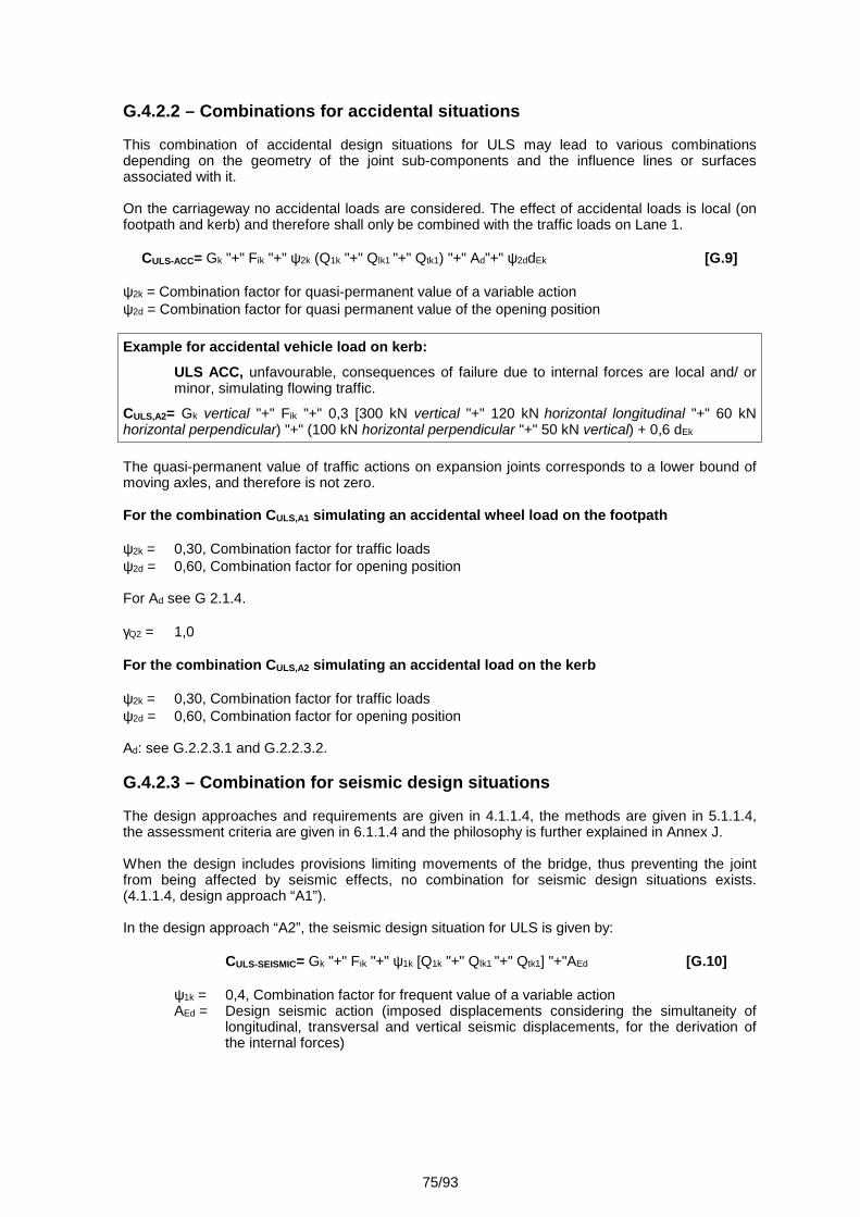
75/93
G.4.2.2 – Combinations for accidental situations
This combination of accidental design situations for ULS may lead to various combinationsdepending on the geometry of the joint sub-components and the influence lines or surfacesassociated with it.
On the carriageway no accidental loads are considered. The effect of accidental loads is local (onfootpath and kerb) and therefore shall only be combined with the traffic loads on Lane 1.
CULS-ACC= Gk "+" Fik "+" 2k (Q1k "+" Qlk1 "+" Qtk1) "+" Ad"+" 2ddEk [G.9]
2k = Combination factor for quasi-permanent value of a variable action2d = Combination factor for quasi permanent value of the opening position
Example for accidental vehicle load on kerb:ULS ACC, unfavourable, consequences of failure due to internal forces are local and/ orminor, simulating flowing traffic.
CULS,A2= Gk vertical "+" Fik "+" 0,3 [300 kN vertical "+" 120 kN horizontal longitudinal "+" 60 kNhorizontal perpendicular) "+" (100 kN horizontal perpendicular "+" 50 kN vertical) + 0,6 dEk
The quasi-permanent value of traffic actions on expansion joints corresponds to a lower bound ofmoving axles, and therefore is not zero.
For the combination CULS,A1 simulating an accidental wheel load on the footpath
2k = 0,30, Combination factor for traffic loads2d = 0,60, Combination factor for opening position
For Ad see G 2.1.4.
Q2 = 1,0
For the combination CULS,A2 simulating an accidental load on the kerb
2k = 0,30, Combination factor for traffic loads2d = 0,60, Combination factor for opening position
Ad: see G.2.2.3.1 and G.2.2.3.2.
G.4.2.3 – Combination for seismic design situations
The design approaches and requirements are given in 4.1.1.4, the methods are given in 5.1.1.4,the assessment criteria are given in 6.1.1.4 and the philosophy is further explained in Annex J.
When the design includes provisions limiting movements of the bridge, thus preventing the jointfrom being affected by seismic effects, no combination for seismic design situations exists.(4.1.1.4, design approach “A1”).
In the design approach “A2”, the seismic design situation for ULS is given by:
CULS-SEISMIC= Gk "+" Fik "+" 1k [Q1k "+" Qlk1 "+" Qtk1] "+"AEd [G.10]
1k = 0,4, Combination factor for frequent value of a variable actionAEd = Design seismic action (imposed displacements considering the simultaneity of
longitudinal, transversal and vertical seismic displacements, for the derivation ofthe internal forces)
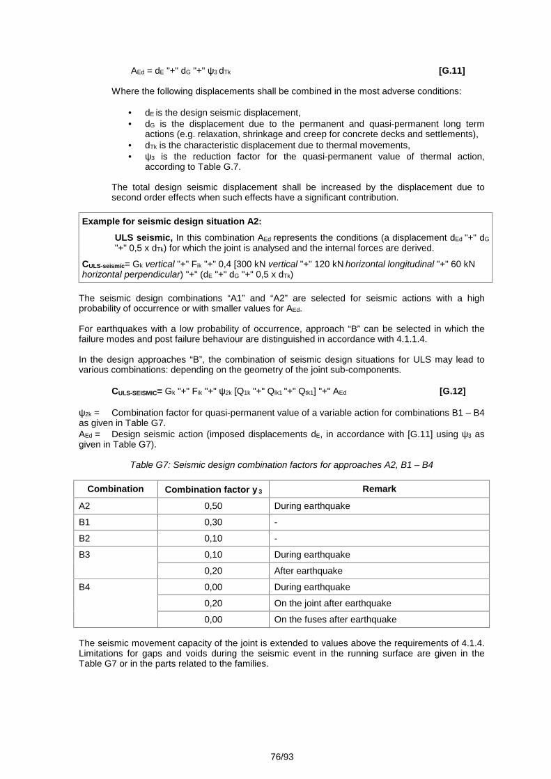
76/93
AEd = dE "+" dG "+" 3 dTk [G.11]
Where the following displacements shall be combined in the most adverse conditions:
dE is the design seismic displacement, dG is the displacement due to the permanent and quasi-permanent long term
actions (e.g. relaxation, shrinkage and creep for concrete decks and settlements), dTk is the characteristic displacement due to thermal movements, 3 is the reduction factor for the quasi-permanent value of thermal action,
according to Table G.7.
The total design seismic displacement shall be increased by the displacement due tosecond order effects when such effects have a significant contribution.
Example for seismic design situation A2:ULS seismic, In this combination AEd represents the conditions (a displacement dEd "+" dG"+" 0,5 x dTk) for which the joint is analysed and the internal forces are derived.
CULS-seismic= Gk vertical "+" Fik "+" 0,4 [300 kN vertical "+" 120 kN horizontal longitudinal "+" 60 kNhorizontal perpendicular) "+" (dE "+" dG "+" 0,5 x dTk)
The seismic design combinations “A1” and “A2” are selected for seismic actions with a highprobability of occurrence or with smaller values for AEd.
For earthquakes with a low probability of occurrence, approach “B” can be selected in which thefailure modes and post failure behaviour are distinguished in accordance with 4.1.1.4.
In the design approaches “B”, the combination of seismic design situations for ULS may lead tovarious combinations: depending on the geometry of the joint sub-components.
CULS-SEISMIC= Gk "+" Fik "+" 2k [Q1k "+" Qlk1 "+" Qtk1] "+" AEd [G.12]
2k = Combination factor for quasi-permanent value of a variable action for combinations B1 – B4as given in Table G7.AEd = Design seismic action (imposed displacements dE, in accordance with [G.11] using 3 asgiven in Table G7).
Table G7: Seismic design combination factors for approaches A2, B1 – B4
Combination Combination factor 3 Remark
A2 0,50 During earthquake
B1 0,30 -
B2 0,10 -
B3 0,10 During earthquake
0,20 After earthquake
B4 0,00 During earthquake
0,20 On the joint after earthquake
0,00 On the fuses after earthquake
The seismic movement capacity of the joint is extended to values above the requirements of 4.1.4.Limitations for gaps and voids during the seismic event in the running surface are given in theTable G7 or in the parts related to the families.
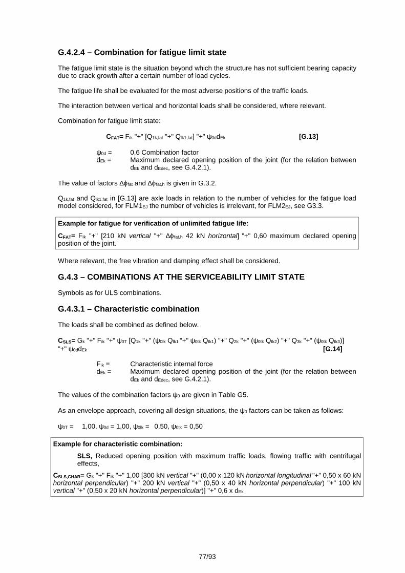
77/93
G.4.2.4 – Combination for fatigue limit state
The fatigue limit state is the situation beyond which the structure has not sufficient bearing capacitydue to crack growth after a certain number of load cycles.
The fatigue life shall be evaluated for the most adverse positions of the traffic loads.
The interaction between vertical and horizontal loads shall be considered, where relevant.
Combination for fatigue limit state:
CFAT= Fik "+" [Q1k,fat "+" Qlk1,fat] "+" 0ddEk [G.13]
0d = 0,6 Combination factordEk = Maximum declared opening position of the joint (for the relation between
dEk and dEdec, see G.4.2.1).
The value of factors fat and fat,h is given in G.3.2.
Q1k,fat and Qlk1,fat in [G.13] are axle loads in relation to the number of vehicles for the fatigue loadmodel considered, for FLM1EJ the number of vehicles is irrelevant, for FLM2EJ, see G3.3.
Example for fatigue for verification of unlimited fatigue life:
CFAT= Fik "+" [210 kN vertical "+" fat,h 42 kN horizontal] "+" 0,60 maximum declared openingposition of the joint.
Where relevant, the free vibration and damping effect shall be considered.
G.4.3 – COMBINATIONS AT THE SERVICEABILITY LIMIT STATE
Symbols as for ULS combinations.
G.4.3.1 – Characteristic combination
The loads shall be combined as defined below.
CSLS= Gk "+" Fik "+" 0T [Q1k "+" (0lk Qlk1 "+" 0tk Qtk1) "+" Q2k "+" (0tk Qtk2) "+" Q3k "+" (0tk Qtk3)]"+" 0ddEk [G.14]
Fik = Characteristic internal forcedEk = Maximum declared opening position of the joint (for the relation between
dEk and dEdec, see G.4.2.1).
The values of the combination factors 0 are given in Table G5.
As an envelope approach, covering all design situations, the 0 factors can be taken as follows:
0T = 1,00, 0d = 1,00, 0lk = 0,50, 0tk = 0,50
Example for characteristic combination:SLS, Reduced opening position with maximum traffic loads, flowing traffic with centrifugaleffects,
CSLS,CHAR= Gk "+" Fik "+" 1,00 [300 kN vertical "+" (0,00 x 120 kN horizontal longitudinal "+" 0,50 x 60 kNhorizontal perpendicular) "+" 200 kN vertical "+" (0,50 x 40 kN horizontal perpendicular) "+" 100 kNvertical "+" (0,50 x 20 kN horizontal perpendicular)] "+" 0,6 x dEk
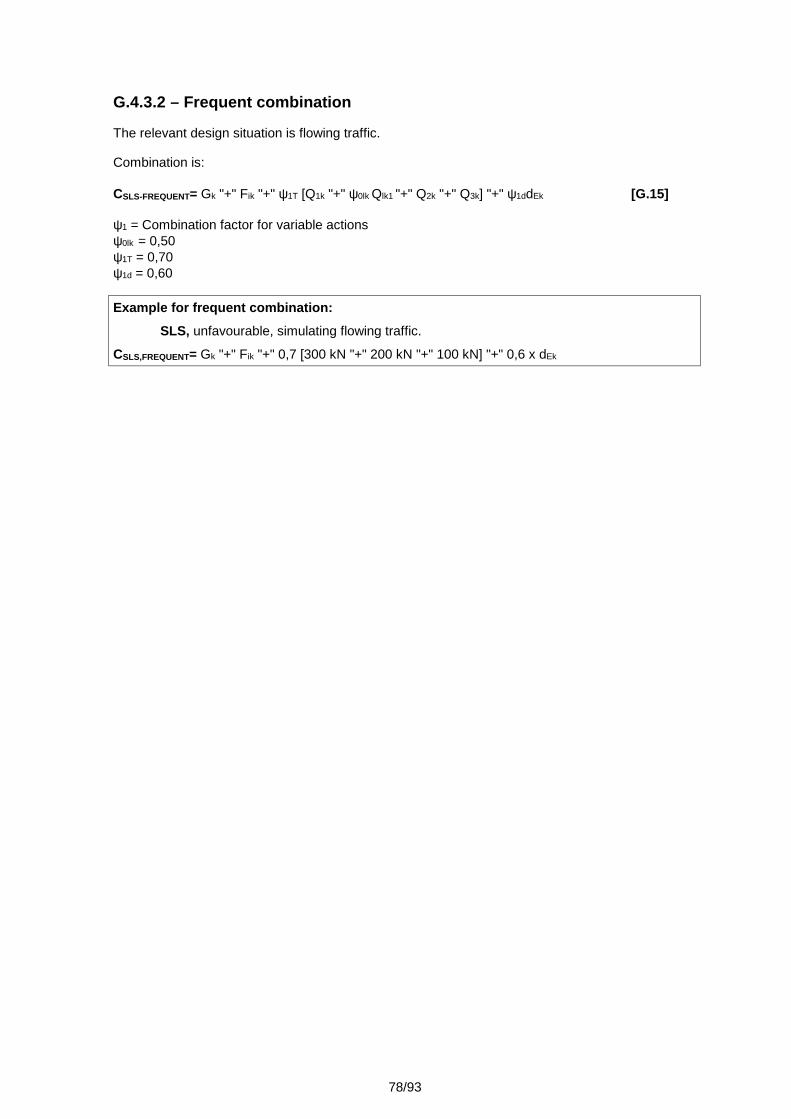
78/93
G.4.3.2 – Frequent combination
The relevant design situation is flowing traffic.
Combination is:
CSLS-FREQUENT= Gk "+" Fik "+" 1T [Q1k "+" 0lk Qlk1 "+" Q2k "+" Q3k] "+" 1ddEk [G.15]
1 = Combination factor for variable actions0lk = 0,501T = 0,701d = 0,60
Example for frequent combination:SLS, unfavourable, simulating flowing traffic.
CSLS,FREQUENT= Gk "+" Fik "+" 0,7 [300 kN "+" 200 kN "+" 100 kN] "+" 0,6 x dEk
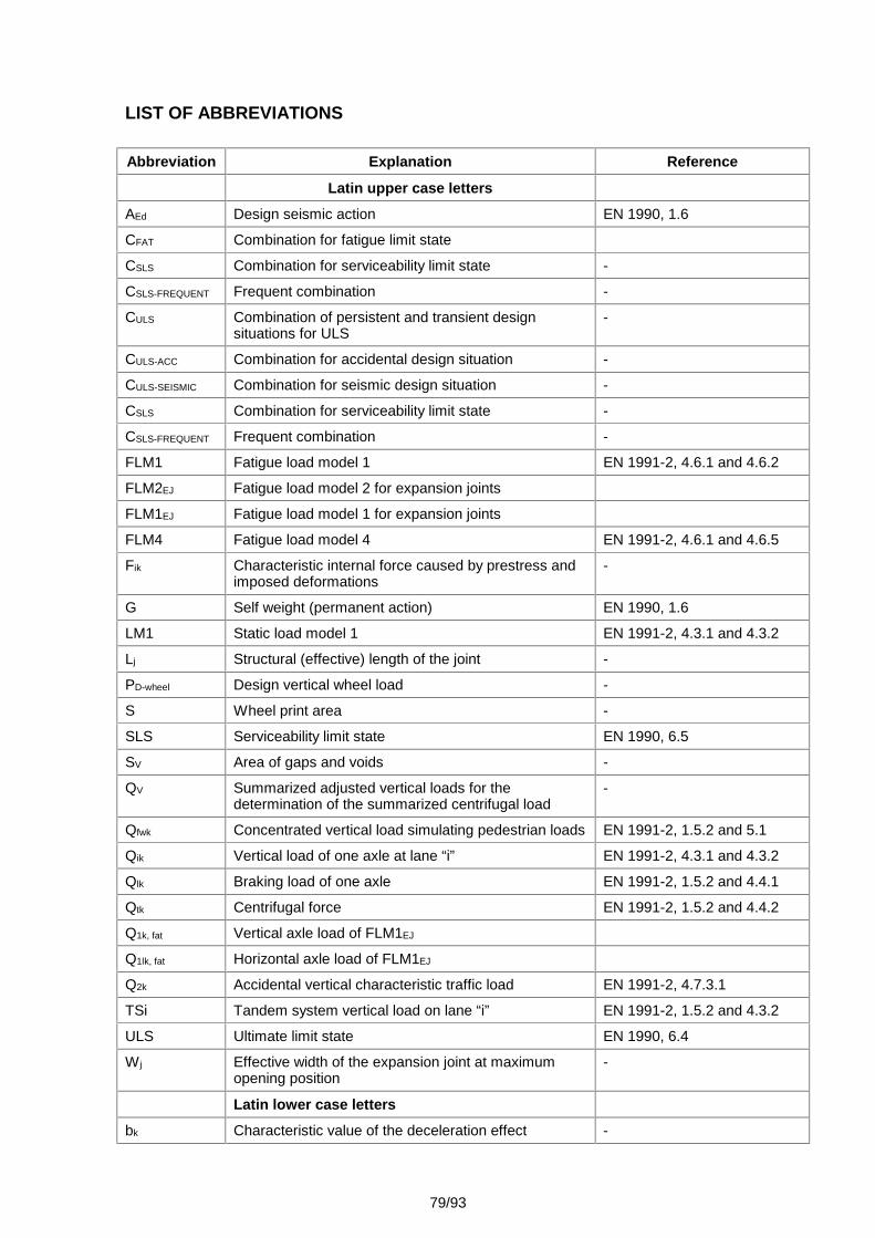
79/93
LIST OF ABBREVIATIONS
Abbreviation Explanation Reference
Latin upper case lettersAEd Design seismic action EN 1990, 1.6
CFAT Combination for fatigue limit state
CSLS Combination for serviceability limit state -
CSLS-FREQUENT Frequent combination -
CULS Combination of persistent and transient designsituations for ULS
-
CULS-ACC Combination for accidental design situation -
CULS-SEISMIC Combination for seismic design situation -
CSLS Combination for serviceability limit state -
CSLS-FREQUENT Frequent combination -
FLM1 Fatigue load model 1 EN 1991-2, 4.6.1 and 4.6.2
FLM2EJ Fatigue load model 2 for expansion joints
FLM1EJ Fatigue load model 1 for expansion joints
FLM4 Fatigue load model 4 EN 1991-2, 4.6.1 and 4.6.5
Fik Characteristic internal force caused by prestress andimposed deformations
-
G Self weight (permanent action) EN 1990, 1.6
LM1 Static load model 1 EN 1991-2, 4.3.1 and 4.3.2
Lj Structural (effective) length of the joint -
PD-wheel Design vertical wheel load -
S Wheel print area -
SLS Serviceability limit state EN 1990, 6.5
SV Area of gaps and voids -
QV Summarized adjusted vertical loads for thedetermination of the summarized centrifugal load
-
Qfwk Concentrated vertical load simulating pedestrian loads EN 1991-2, 1.5.2 and 5.1
Qik Vertical load of one axle at lane “i” EN 1991-2, 4.3.1 and 4.3.2
Qlk Braking load of one axle EN 1991-2, 1.5.2 and 4.4.1
Qtk Centrifugal force EN 1991-2, 1.5.2 and 4.4.2
Q1k, fat Vertical axle load of FLM1EJ
Q1lk, fat Horizontal axle load of FLM1EJ
Q2k Accidental vertical characteristic traffic load EN 1991-2, 4.7.3.1
TSi Tandem system vertical load on lane “i” EN 1991-2, 1.5.2 and 4.3.2
ULS Ultimate limit state EN 1990, 6.4
W j Effective width of the expansion joint at maximumopening position
-
Latin lower case lettersbk Characteristic value of the deceleration effect -
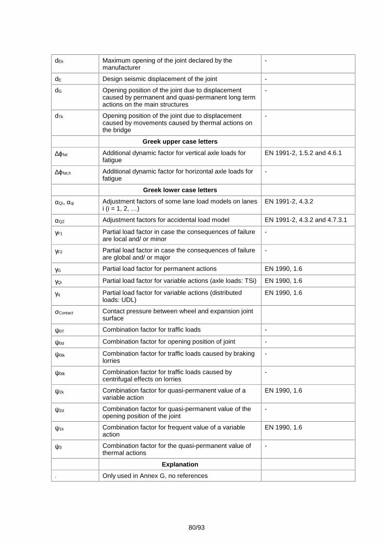
80/93
dEk Maximum opening of the joint declared by themanufacturer
-
dE Design seismic displacement of the joint -
dG Opening position of the joint due to displacementcaused by permanent and quasi-permanent long termactions on the main structures
-
dTk Opening position of the joint due to displacementcaused by movements caused by thermal actions onthe bridge
-
Greek upper case letters
fat Additional dynamic factor for vertical axle loads forfatigue
EN 1991-2, 1.5.2 and 4.6.1
fat,h Additional dynamic factor for horizontal axle loads forfatigue
-
Greek lower case letters
Qi, qi Adjustment factors of some lane load models on lanesi (i = 1, 2, …)
EN 1991-2, 4.3.2
Q2 Adjustment factors for accidental load model EN 1991-2, 4.3.2 and 4.7.3.1
F1 Partial load factor in case the consequences of failureare local and/ or minor
-
F2 Partial load factor in case the consequences of failureare global and/ or major
-
G Partial load factor for permanent actions EN 1990, 1.6
Qi Partial load factor for variable actions (axle loads: TSi) EN 1990, 1.6
q Partial load factor for variable actions (distributedloads: UDL)
EN 1990, 1.6
Contact Contact pressure between wheel and expansion jointsurface
0T Combination factor for traffic loads -
0d Combination factor for opening position of joint -
0lk Combination factor for traffic loads caused by brakinglorries
-
0tk Combination factor for traffic loads caused bycentrifugal effects on lorries
-
2k Combination factor for quasi-permanent value of avariable action
EN 1990, 1.6
2d Combination factor for quasi-permanent value of theopening position of the joint
-
1k Combination factor for frequent value of a variableaction
EN 1990, 1.6
3 Combination factor for the quasi-permanent value ofthermal actions
-
Explanation
- Only used in Annex G, no references
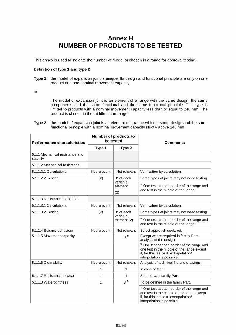
81/93
Annex HNUMBER OF PRODUCTS TO BE TESTED
This annex is used to indicate the number of model(s) chosen in a range for approval testing.
Definition of type 1 and type 2
Type 1: the model of expansion joint is unique. Its design and functional principle are only on oneproduct and one nominal movement capacity.
or
The model of expansion joint is an element of a range with the same design, the samecomponents and the same functional and the same functional principle. This type islimited to products with a nominal movement capacity less than or equal to 240 mm. Theproduct is chosen in the middle of the range.
Type 2: the model of expansion joint is an element of a range with the same design and the samefunctional principle with a nominal movement capacity strictly above 240 mm.
Performance characteristicsNumber of products to
be tested CommentsType 1 Type 2
5.1.1 Mechanical resistance andstability
5.1.1.2 Mechanical resistance
5.1.1.2.1 Calculations Not relevant Not relevant Verification by calculation.
5.1.1.2.2 Testing (2) 3* of eachvariableelement
(2)
Some types of joints may not need testing.
* One test at each border of the range andone test in the middle of the range.
5.1.1.3 Resistance to fatigue
5.1.1.3.1 Calculations Not relevant Not relevant Verification by calculation.
5.1.1.3.2 Testing (2) 3* of eachvariableelement (2)
Some types of joints may not need testing.
* One test at each border of the range andone test in the middle of the range.
5.1.1.4 Seismic behaviour Not relevant Not relevant Select approach declared.5.1.1.5 Movement capacity 1 3 * Except where required in family Part:
analysis of the design.* One test at each border of the range andone test in the middle of the range exceptif, for this last test, extrapolation/interpolation is possible.
5.1.1.6 Cleanability Not relevant Not relevant Analysis of technical file and drawings.
1 1 In case of test.
5.1.1.7 Resistance to wear 1 1 See relevant family Part.
5.1.1.8 Watertightness 1 3 * To be defined in the family Part.
* One test at each border of the range andone test in the middle of the range exceptif, for this last test, extrapolation/interpolation is possible.
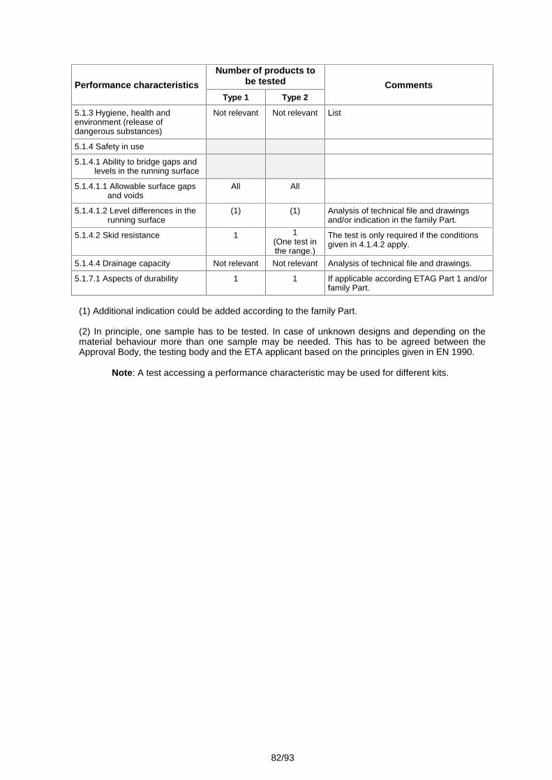
82/93
Performance characteristicsNumber of products to
be tested CommentsType 1 Type 2
5.1.3 Hygiene, health andenvironment (release ofdangerous substances)
Not relevant Not relevant List
5.1.4 Safety in use
5.1.4.1 Ability to bridge gaps andlevels in the running surface
5.1.4.1.1 Allowable surface gapsand voids
All All
5.1.4.1.2 Level differences in therunning surface
(1) (1) Analysis of technical file and drawingsand/or indication in the family Part.
5.1.4.2 Skid resistance 1 1(One test inthe range.)
The test is only required if the conditionsgiven in 4.1.4.2 apply.
5.1.4.4 Drainage capacity Not relevant Not relevant Analysis of technical file and drawings.
5.1.7.1 Aspects of durability 1 1 If applicable according ETAG Part 1 and/orfamily Part.
(1) Additional indication could be added according to the family Part.
(2) In principle, one sample has to be tested. In case of unknown designs and depending on thematerial behaviour more than one sample may be needed. This has to be agreed between theApproval Body, the testing body and the ETA applicant based on the principles given in EN 1990.
Note: A test accessing a performance characteristic may be used for different kits.
83/93
Annex JSEISMIC APPROACH
DESIGN PHILOSOPHY FOR RBEJ
The objective of this annex is to give sufficient background information to the Approval Bodies forthe consideration of the seismic design situation to be used in the approval procedure.
J.1 – INTRODUCTION
For the total design displacement under seismic conditions in accordance with EN 1998-2, anadequate structural gap is required to protect critical or major structural elements from damage.
The design displacement is determined under consideration of seismic actions and the long-termeffect of the permanent and quasi-permanent actions and includes an appropriate fraction of thedisplacement due to thermal movements.
Generally after the design seismic event, sufficient bearing capacity shall remain for emergencyvehicles with appropriate reliability.
Local damage to the expansion joint due to the design earthquake is admissible.
1) For earthquakes with high probability of occurrence only damage with no need ofimmediate repair and no influence to the traffic safety are generally allowed.
2) The total value of the design displacement under seismic conditions dEd by reference toEN 1998-2, 2.3.6.3 is determined as follows:
dEd = dE + dG + 2dT
Where: dE is the design seismic displacement, dG is the displacement due to the permanent and quasi-permanent actions
measured over the long term (e.g. post-tensioning, shrinkage and creep forconcrete decks),
dT is the displacement due to thermal movements, 2 is the reduction factor for the quasi-permanent value of thermal action,
according to Tables A2.1, A2.2 or A2.3 of Annex A2 of EN 1990. The total designseismic displacement shall be increased by the displacement due to second ordereffects when such effects have a significant contribution.
Attention shall be paid to the supporting conditions induced by larger initial bridge deck gap and tothe influence of the displacement speed and acceleration during the earthquake.
Values of the displacement generated by seismic phenomena can be reduced by seismic devicesand/or provisions in the bridge design limiting the structure movement.
J.2 – MOVEMENT CAPACITY CASES
A) Movement capacity design
This design method can be applied for bridges with small seismic displacements (recommendedvalue dEd ≤ 200 mm) and depends on techno-economical considerations.
A-1 - Expansion joints with movement capacity SLS condition even during earthquake.
Standard expansion joints can be used if they provide under serviceability conditions according to4.1.1.5 the total movement capacity required for displacement dEd.
84/93
A-2 -Expansion joints with movement capacity for the total displacement dEd
The seismic movement capacity of the joint is extended to values above the requirements of4.1.4.1. Limitations for gaps and voids during the seismic event in the running surface are given inthe Table 4.1.4.1 or in the parts related to the families.
The resistance to static actions during the earthquake shall be checked for the frequentcombination of actions as per EN 1990. No fatigue design is required for this condition.
The expansion joint is assumed to be resistant to any other kind of effects given in this ETAG afterthe design earthquake and no repair work has to be applied.
B) Restricted movement and load capacity design
For larger seismic displacements (recommended value dEd > 200 mm) the design according tomode A becomes uneconomic. Therefore smaller or controlled damage can be accepted for severeearthquakes. Structural gaps shall accommodate appropriate fractions of the design seismicdisplacement and thermal movement, after allowing for any long term creep and shrinkage effects,so that damage under frequent earthquakes can be avoided. The appropriate values of suchfractions depend on national regulations.
Earthquakes with high probability of occurrence during the intended working life of the expansionjoint should not create any damage and therefore be in accordance with the requirements of one ofthe modes A. Appropriate values for the seismic movement have to be used. In the absence of anexplicit optimisation the following value is recommended:
- 40% of the design seismic displacement and- the frequent combination of other movements in accordance with EN 1990.
J.3 – BRIDGES WITH FUSIBLE LINKS
Specially to isolate bridges against seismic inputs and to limit seismic actions, fusible links areprovided to bear horizontal loads during the service condition. After the fuse is activated, themovement design requirements (amplitude and direction) for the expansion joint are changed.
Such functioning is out of the scope of this ETAG.
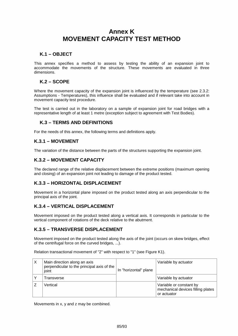
85/93
Annex KMOVEMENT CAPACITY TEST METHOD
K.1 – OBJECT
This annex specifies a method to assess by testing the ability of an expansion joint toaccommodate the movements of the structure. These movements are evaluated in threedimensions.
K.2 – SCOPE
Where the movement capacity of the expansion joint is influenced by the temperature (see 2.3.2:Assumptions - Temperatures), this influence shall be evaluated and if relevant take into account inmovement capacity test procedure.
The test is carried out in the laboratory on a sample of expansion joint for road bridges with arepresentative length of at least 1 metre (exception subject to agreement with Test Bodies).
K.3 – TERMS AND DEFINITIONS
For the needs of this annex, the following terms and definitions apply.
K.3.1 – MOVEMENT
The variation of the distance between the parts of the structures supporting the expansion joint.
K.3.2 – MOVEMENT CAPACITY
The declared range of the relative displacement between the extreme positions (maximum openingand closing) of an expansion joint not leading to damage of the product tested.
K.3.3 – HORIZONTAL DISPLACEMENT
Movement in a horizontal plane imposed on the product tested along an axis perpendicular to theprincipal axis of the joint.
K.3.4 – VERTICAL DISPLACEMENT
Movement imposed on the product tested along a vertical axis. It corresponds in particular to thevertical component of rotations of the deck relative to the abutment.
K.3.5 – TRANSVERSE DISPLACEMENT
Movement imposed on the product tested along the axis of the joint (occurs on skew bridges, effectof the centrifugal force on the curved bridges, ...).
Relation transactional movement of "2" with respect to "1" (see Figure K1).
X Main direction along an axisperpendicular to the principal axis of thejoint In "horizontal" plane
Variable by actuator
Y Transverse Variable by actuator
Z Vertical Variable or constant bymechanical devices filling platesor actuator
Movements in x, y and z may be combined.
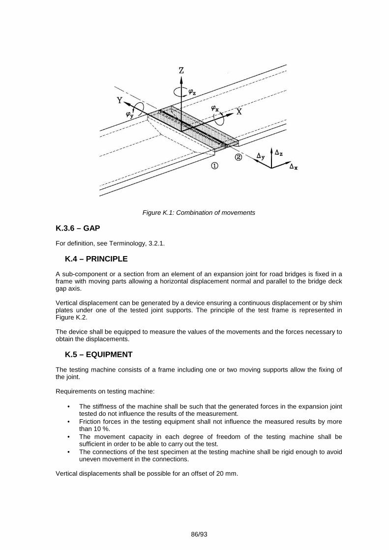
86/93
Figure K.1: Combination of movements
K.3.6 – GAP
For definition, see Terminology, 3.2.1.
K.4 – PRINCIPLE
A sub-component or a section from an element of an expansion joint for road bridges is fixed in aframe with moving parts allowing a horizontal displacement normal and parallel to the bridge deckgap axis.
Vertical displacement can be generated by a device ensuring a continuous displacement or by shimplates under one of the tested joint supports. The principle of the test frame is represented inFigure K.2.
The device shall be equipped to measure the values of the movements and the forces necessary toobtain the displacements.
K.5 – EQUIPMENT
The testing machine consists of a frame including one or two moving supports allow the fixing ofthe joint.
Requirements on testing machine:
The stiffness of the machine shall be such that the generated forces in the expansion jointtested do not influence the results of the measurement.
Friction forces in the testing equipment shall not influence the measured results by morethan 10 %.
The movement capacity in each degree of freedom of the testing machine shall besufficient in order to be able to carry out the test.
The connections of the test specimen at the testing machine shall be rigid enough to avoiduneven movement in the connections.
Vertical displacements shall be possible for an offset of 20 mm.
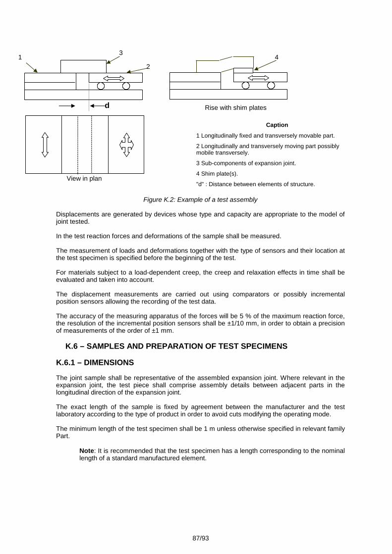
87/93
Caption
1 Longitudinally fixed and transversely movable part.
2 Longitudinally and transversely moving part possiblymobile transversely.
3 Sub-components of expansion joint.
4 Shim plate(s).
"d" : Distance between elements of structure.
Figure K.2: Example of a test assembly
Displacements are generated by devices whose type and capacity are appropriate to the model ofjoint tested.
In the test reaction forces and deformations of the sample shall be measured.
The measurement of loads and deformations together with the type of sensors and their location atthe test specimen is specified before the beginning of the test.
For materials subject to a load-dependent creep, the creep and relaxation effects in time shall beevaluated and taken into account.
The displacement measurements are carried out using comparators or possibly incrementalposition sensors allowing the recording of the test data.
The accuracy of the measuring apparatus of the forces will be 5 % of the maximum reaction force,the resolution of the incremental position sensors shall be ±1/10 mm, in order to obtain a precisionof measurements of the order of ±1 mm.
K.6 – SAMPLES AND PREPARATION OF TEST SPECIMENS
K.6.1 – DIMENSIONS
The joint sample shall be representative of the assembled expansion joint. Where relevant in theexpansion joint, the test piece shall comprise assembly details between adjacent parts in thelongitudinal direction of the expansion joint.
The exact length of the sample is fixed by agreement between the manufacturer and the testlaboratory according to the type of product in order to avoid cuts modifying the operating mode.
The minimum length of the test specimen shall be 1 m unless otherwise specified in relevant familyPart.
Note: It is recommended that the test specimen has a length corresponding to the nominallength of a standard manufactured element.
Rise with shim plates
4
d
312
View in plan
88/93
K.6.2 – CONTROL OF SAMPLES
The product tested shall be in conformity with the manufacturing drawings and the specificationsincluding the tolerances.
It shall be verified that the samples comply with the specifications.
The number of test samples is one. It is recommended for products which show a variation infunctioning, to use 3 test samples.
K.6.3 – INSTALLATION OF SAMPLES ON THE TEST FRAME
The product to be tested shall be installed in the testing rig under the control of the manufacturerand shall comply with the installation procedure.
K.7 – PROCEDURE
K.7.1 – TESTING CONDITIONS
The test is carried out under the following conditions:
Test temperature
The ambient temperature during the tests shall be between +5 °C and +35 °C. Whererelevant, the family Part gives details if the ambient temperature, defined in this clause, isnot appropriate for carrying out the test and which procedures for testing are applicable.
Test speed
The speed of longitudinal and transverse displacements during the test shall not exceed1 mm/s between the stages of observation. A complete cycle shall not exceed 24 hours.
K.7.2 – TEST PROCEDURE
Check and record the test temperature.
Fix the devices of measuring of displacements so that the movements are correctly recorded.
The test specimen shall be subjected to movements which simulate opening and closing of thejoint.
The test comprises 6 cycles (See Figure K.3). For each cycle, the maximum relative displacementof the test specimen as designed by the producer is subdivided into a minimum of 4 steps, each25 % of the maximum relative displacement. The test may start at any desired position within themaximum relative displacement. After completion of each step, a dwell period is allowed.
During cycle 1 and cycle 5, the displacements are measured together with the reaction forces.
During the 5th cycle, the transverse movement capacity is verified in combination with the totalrange of longitudinal movement and the values of corresponding reaction forces are recorded.
For the joints having a symmetrical operation under transverse solicitation, the checking will bedone in one direction only.
In a 6th cycle the supports are positioned with a vertical offset in order to simulate the unevennessof supports. Only opening and closing movements are applied, no transverse movements. Whenthe joint has a different behaviour for an upward movement compared to a downward movementboth directions shall be measured.
The behaviour and the appearance of the joint shall be recorded.
Note: Parts of this test procedure will be used for the derivation of fatigue tests by imposeddeformations according to 4.1.1.3.
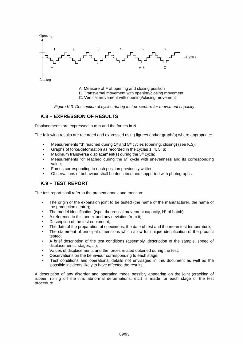
89/93
A: Measure of F at opening and closing positionB: Transversal movement with opening/closing movementC: Vertical movement with opening/closing movement
Figure K.3: Description of cycles during test procedure for movement capacity
K.8 – EXPRESSION OF RESULTS
Displacements are expressed in mm and the forces in N.
The following results are recorded and expressed using figures and/or graph(s) where appropriate:
Measurements "d" reached during 1st and 5th cycles (opening, closing) (see K.3); Graphs of force/deformation as recorded in the cycles 1, 4, 5, 6; Maximum transverse displacement(s) during the 5th cycle; Measurements "d" reached during the 6th cycle with unevenness and its corresponding
value; Forces corresponding to each position previously written; Observations of behaviour shall be described and supported with photographs.
K.9 – TEST REPORT
The test report shall refer to the present annex and mention:
The origin of the expansion joint to be tested (the name of the manufacturer, the name ofthe production centre);
The model identification (type, theoretical movement capacity, N° of batch); A reference to this annex and any deviation from it; Description of the test equipment; The date of the preparation of specimens, the date of test and the mean test temperature; The statement of principal dimensions which allow for unique identification of the product
tested; A brief description of the test conditions (assembly, description of the sample, speed of
displacements, stages, ...); Values of displacements and the forces related obtained during the test; Observations on the behaviour corresponding to each stage; Test conditions and operational details not envisaged in this document as well as the
possible incidents likely to have affected the results.
A description of any disorder and operating mode possibly appearing on the joint (cracking ofrubber, rolling off the rim, abnormal deformations, etc.) is made for each stage of the testprocedure.
90/93
Annex LWATERTIGHTNESS TEST METHOD
L.1 – SCOPE
This annex describes a test method for water tightness of an expansion joint.
This test method is not intended as a verification of drainage systems or collection of water bymeans of additional devices.
This annex gives guidance on how to test whether an expansion joint, in its design (thus before theproduct is exposed to traffic loads), is ready to prevent percolation of water (Remark: percolation isdifferent to moisture at bottom surface).
The test is carried out to verify that water cannot pass through the expansion joint.
The test is carried out on a representative sample of an expansion joint in laboratory conditions outof traffic.
In the case of design of an expansion joint where the device ensuring the waterproofing (or theexistence of a discharge drainage system) is positioned below the riding surface (beyond 50 mm),the method of test has to be agreed between the manufacturer, Approval Body and the testinglaboratory.
L.2 – DEFINITIONS
See 3.2 of this ETAG.
L.3 – PRINCIPLE
The full-scale representative sample of the expansion joint includes all components and at leastone connection if applicable and an upstand.
The test shall be carried out on one sample.
The test involved subjecting the sample of the expansion joint to the action of a defined head ofwater on the joint.
There shall be no moisture under the joint.
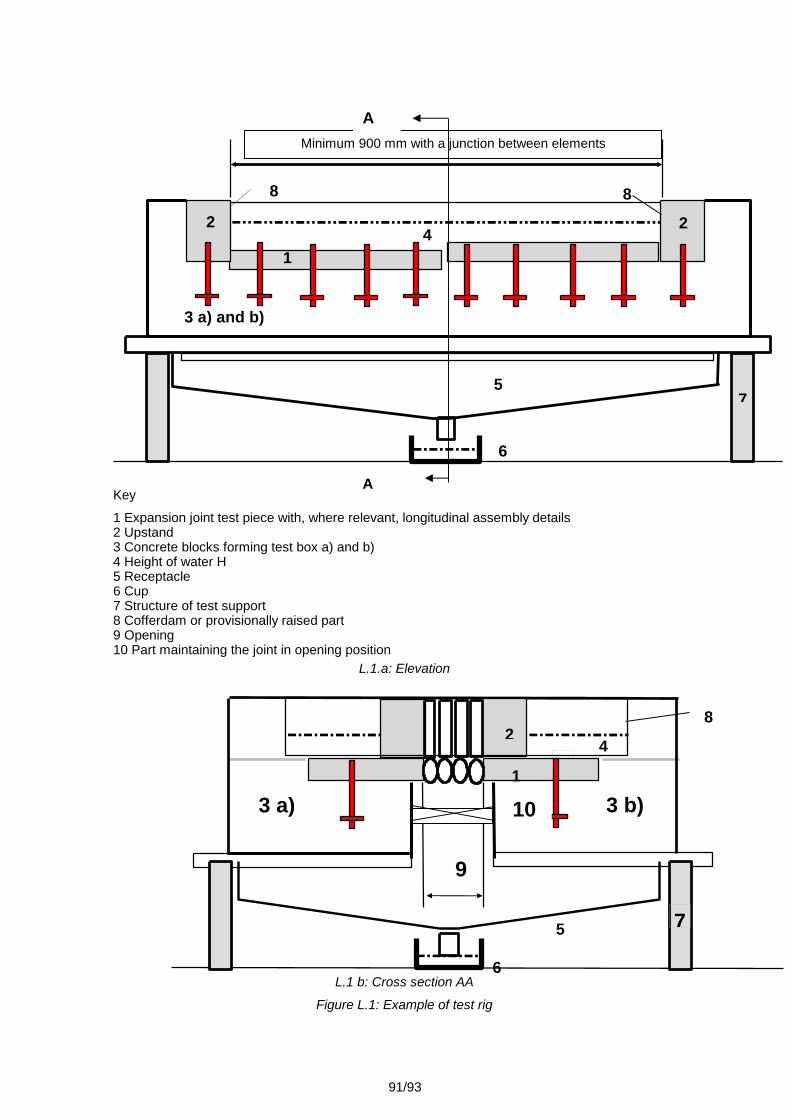
91/93
Key
1 Expansion joint test piece with, where relevant, longitudinal assembly details2 Upstand3 Concrete blocks forming test box a) and b)4 Height of water H5 Receptacle6 Cup7 Structure of test support8 Cofferdam or provisionally raised part9 Opening10 Part maintaining the joint in opening position
L.1.a: Elevation
L.1 b: Cross section AA
Figure L.1: Example of test rig
6
Minimum 900 mm with a junction between elements
2
1
3 a) and b)
4
57
8
28
8
4
9
1
2
5
6
3 a) 10 3 b)
4
7
A
A
92/93
L.4 – SAMPLES AND PREPARATION OF TEST SPECIMENS
L.4.1 – DIMENSIONS
The full-scale representative sample of the expansion joint shall include all components and atleast one connection if applicable and an upstand.
The joint sample shall be representative of the assembled expansion joint. Where relevant in theexpansion joint, the test piece shall comprise assembly details between adjacent parts in thelongitudinal direction of the expansion joint. The exact length of the sample shall be fixed byagreement between the manufacturer, the Approval Body and the test laboratory according to thetype of product.
The minimum length of the test specimen shall be 1 m.
L.4.2 – CONTROL OF SAMPLES
The tested product shall be in conformity with the manufacturing drawings and the specificationsincluding the tolerances.
It shall be verified that the samples comply with the specifications.
The number of test samples shall be one.
L.4.3 – INSTALLATION OF SAMPLES ON THE TEST FRAME
The product to be tested shall be installed in the testing rig under the control of the manufacturerand shall comply with the procedure established by the manufacturer for the installation on the testrig.
L.4.4 – TEST RIG
The principle of the test rig is shown in Figure L.1.
L.5 – TEST PROCEDURE
L.5.1 – BEGINNING OF THE TEST
The test shall be carried out after the materials are fully cured and set in the test rig in accordancewith the installation procedure manual, within a time defined by agreement between themanufacturer, the Approval Body and the testing laboratory.
L.5.2 – TEST TEMPERATURE
The temperature during the test shall be between +5 °C and +30 °C.
L.5.3 – EXECUTION OF THE TEST
The sample is assembled in accordance with Figure L.1. The opening of the joint shall be fixed atthe nominal maximum opening declared by the manufacturer of the product.
Where relevant, the value of opening used for testing is modified in the family Part.
Note: Depending of the type of product and the condition of functioning, the opening will bedefined in the worst condition of opening.
The test is carried out with potable water.
The minimum head shall be 30 mm at the highest location of the sample. Where relevant, deviationfrom this last value is specified in each family Part.
Note: A maximum head larger than 50 mm is not considered necessary.
93/93
The duration of the test is 6 hours.
During the testing continuous visual inspection shall be carried out to detect leakage. In the eventof leakage the test shall be stopped. Locations where leakage has been observed are to bereported.
L.6 – EXPRESSION OF THE RESULTS
The openings are stated in millimetres.
The head shall be given in millimetres.
Times are expressed in hours. The air temperature during the test is expressed in degrees Celsius.
Pass/fail results.
In case of failure the location and the significance shall be reported.
L.7 – TEST REPORT
The test report shall include:
The origin of the expansion joint to be tested (the name of the manufacturer, the name of theproduction centre);
The model identification (type, theoretical movement capacity, N° of batch); A reference to this annex and any deviation from it; Description of the test equipment; The date of the preparation of specimens, the date of test and the test mean temperature; The statement of principal dimensions which allow for unique identification of the product
tested; A brief description of the test conditions (head of water, opening test, test duration, description
of the sample, ...); Test conditions and operational details not envisaged in this document as well as the possible
incidents likely to have affected the results. Results of watertighness test (pass, fail, leakage location, etc.).