guide to taking a representative sample
TRANSCRIPT

Guide to Taking a Representative Sample
2
Table of contents Chapter 1: General information ................................................................................................................................ 3
1.1 Purpose ...................................................................................................................................................... 3
1.2 Sources of sampling error .......................................................................................................................... 4
1.3 Sampling methods ..................................................................................................................................... 6
1.4 Glossary of terms ....................................................................................................................................... 6
Chapter 2: Pneumatic truck probe sampling ............................................................................................................. 8
2.1 Overview .................................................................................................................................................... 8
2.2 Installation ................................................................................................................................................. 8
2.3 Components ............................................................................................................................................ 10
2.4 Adjustments............................................................................................................................................. 17
2.5 Operation ................................................................................................................................................. 21
2.6 Maintenance ............................................................................................................................................ 23
Chapter 3: Manual stream sampling ....................................................................................................................... 24
3.1 Overview .................................................................................................................................................. 24
3.2 Hand scoops ............................................................................................................................................ 24
3.3 Methods for stream sampling ................................................................................................................. 25
Chapter 4: Manual sampling of static grain in truck and railcar conveyances ........................................................ 28
4.1 Overview .................................................................................................................................................. 28
4.2 Double sleeve trier .................................................................................................................................. 28
4.3 Method for using double sleeve trier vertically ...................................................................................... 29
4.4 Probing patterns ...................................................................................................................................... 29
Chapter 5: Reducing your composite grain sample ................................................................................................ 31
5.1 Overview .................................................................................................................................................. 31
5.2 Boerner-type divider ............................................................................................................................... 31
5.3 Sample dividing with pails ....................................................................................................................... 32
Contact us ................................................................................................................................................................ 34

3
Chapter 1: General information 1.1 Purpose The Guide to Taking a Representative Sample outlines the single most important task related to determining the quality of a parcel of grain: obtaining a sample that represents a lot or consignment in all respects. These samples may be drawn by automatic or manual means. This guide will describe methods that can be used to successfully collect a representative sample on farm, or when grain is delivered to a grain handling facility. It is important to understand the basic principles of unbiased sampling, and then to choose the correct sampling process for the lot you are sampling.
This Guide does not supersede the Sampling Systems Handbook and Approval Guide (Sampling Handbook).
The Sampling Handbook outlines the Canadian Grain Commission’s policies and procedures for automatic mechanical sampling systems used to obtain official samples for inward receipt and outward discharge of grain at licensed grain handling facilities. The Sampling Handbook also includes information on Canadian Grain Commission - approved sampling methods for the Accredited Container Sampling Program and the Certified Container Sampling Program. The Sampling Handbook’s section on manual sampling may be used at the discretion of the Canadian Grain Commission when a lot of grain cannot be sampled by automatic mechanical sampling means.
This guide is intended for use by Canadian Grain Commission staff, producers, and members of the grain industry. It contains the following chapters:
Chapter 1: General information Describes the purpose of the document, sources of sampling errors, sampling methods and glossary of terms.
Chapter 2: Pneumatic truck probes Describes the installation, components, adjustments, operation and maintenance of pneumatic truck probes when sampling truck conveyances.
Chapter 3: Manual stream sampling Describes the equipment and methods used for manual stream sampling.
Chapter 4: Manual sampling of static grain in truck, railcar and container conveyances Describes the equipment and methods used for manual sampling of static grain.
Chapter 5: Reduce your composite grain sample Describes the equipment and procedures used to mix and divide grain samples into smaller representative portions.

4
1.2 Sources of sampling error There are 5 principle sources of error in grain sampling. The first 2 cannot be controlled due to the very nature of the product (grain) being sampled. The remaining 3 sources can be managed by utilizing correct sampling processes that are fit for that purpose.
Cannot be controlled (see examples in Figures 1, 2 and 3):
1. Grouping or segregation error: all components (grain or dockage material) may settle and form layers (stratification) according to their size and density (e.g. heavy components settle below light weight components).
2. Long-range periodic and non-periodic heterogeneity fluctuation: components fluctuate during grain flow due to the process of moving the grain (e.g. bin unload). The composition of a sample taken at the beginning of the grain flow may be different from the composition of a sample taken later in the grain movement.
Can be managed (see example in Figure 4):
3. Delimiting error: when any part of the grain does not have an equal chance at being sampled. 4. Extraction error: when the sample is not taken by appropriate equipment and/or proper sampling
procedures. 5. Preparation error: when the sample is mishandled, including incorrect sample division, sample integrity
not being preserved, etc.
Figure 1: Stratification of grain in motion

5
Figure 2: Stratification of grain when unloading
Figure 3: Example of stratification of material in a conveyance

6
Figure 4: Recommended probe sampling patterns to manage extraction error
1.3 Sampling methods There are many opportunities to manually sample grain, such as when filling a bin, after loading a truck, while unloading a truck, or transferring grain. There are also many different methods and types of equipment available to sample with. This guide describes best practices to use to obtain a representative sample when using a selected method.
• Pneumatic truck probe – manually controlled • Hand scoop – manual stream sampling • Double sleeve trier – manual static sampling
1.4 Glossary of terms This section describes common terms and descriptions used in sampling grain in Canada.
Alteration Modifications or changes made to the sampling system after the system was last examined and/or tested. This includes, but is not limited to, changes to the sampling device, drive mechanism or sample delivery system. Composite sample A sample formed by combining and mixing all of the primary samples taken from the lot. Lockout control Device or process used to disconnect the main power supply to all the sampling equipment and bring the entire sampling system to a zero-energy state. Manual stream sampling Obtaining a sample by inserting a recommended sampling device at alternating points (left, middle, right) and regularly timed intervals for each sampling action across a falling stream or moving belt stream from the start to the finish of the grain transfer.
7
Operating controls Controls used by operators for the normal operation of a mechanical sampling system. These include, but are not limited to, on/off control panel switches, boom controls, joystick or light controls. Primary sample A sample taken from a lot of grain during one single sampling action. Sample divider A mechanical or gravitational divider used to reduce the size of the sample obtained from the sampling process. Sampling action The act of capturing grain from the lot; e.g., by one single entry and withdrawal of the pneumatic truck probe or double sleeve trier, or one scooping action of falling grain stream or grain flowing on a belt. Sub-sample A portion of the composite sample obtained by mixing and dividing the composite by a recommended sample dividing method.

8
Chapter 2: Pneumatic truck probe sampling 2.1 Overview Pneumatic truck probe sampling systems are used to sample truck conveyances with the use of a sampling probe (compartmentalized or core) that is inserted into a bulk lot of grain. When the probe reaches the maximum depth of a conveyance, a pneumatic recovery system transports the sample from the probe and delivers the sample, through a series of delivery lines, to a sample collection unit.
Compartment type and core type probes with controlled air pressures are the recommended probe types for use by the industry. The installation, components, adjustments, operation and maintenance of the pneumatic truck probe sampling system are all important to ensure that the system is operating efficiently, and as designed.
Figure 5: Diagram of a pneumatic core type probe system
2.2 Installation The pneumatic truck probe foundation, drive mechanism, base structure, booms, sampling component, sample delivery system and sample collector must be installed as prescribed by the manufacturer. This will help ensure that the sample taken from the sampled lot and delivered to the inspection office for analysis is representative.
The foundation and base structures mounting plate must be installed at the proper height from ground level (not too high or too low). If the probe is installed outside of manufacturer specifications, it may not be able to reach the entire depth of a conveyance, depending on the probe’s length and reach of the boom.

9
Pneumatic truck probes and supporting sample delivery components come in various makes and models. Purchase and install equipment that best suits your environmental working conditions and expected work volumes.
• Protect probes from adverse weather conditions (during sampling and when at rest) to help alleviate issues with moisture contamination and equipment performance.
• Adverse weather such as rain, snow and cold will negatively affect compartment type probes’ performance more so than core type probes due to their design differences (see description of each type in section 2.3: Components).
• Manufacturers design and build various models to accommodate a range of workloads. Consider the expected work volumes, such as annual tonnage and/or number of trucks to be sampled, when selecting this type of sampling equipment.
Sample delivery lines from the truck probe to the inspection area must follow the most direct route with as few bends as possible. Follow manufacturer installation guidelines and the information in the following section to help minimize impacts to the primary sample, such as cracked corn and foreign material (CCFM) in corn. Sample delivery systems are typically installed above ground, but underground installations are also an option.
In both types of installations:
• Delivery lines must not have a turn radius greater than 90 degrees and must be laid vertically or horizontally as much as possible.
• The delivery line conduit must be cut squarely and the inside edges honed to remove any roughness or burrs.
• Conduits for negative or positive air pressures must be connected with airtight couplers where necessary.
• An electrical path must be maintained over the entire delivery system with suitable grounding points to discharge any static build up.
Aluminum or Stainless Steel Morris Couplers Figure 6: Sample delivery lines and couplers
Vacuum pumps, air supply pumps and sample collector installations are very important to the effectiveness of sampling, transporting and collecting of a representative sample. Manufacturers supply these components based on configuration and installation requirements.

10
2.3 Components All components, including drive mechanism (hydraulic or electric), pneumatic truck probe structure, sampling device, sample delivery system and sample collection unit, must be constructed of materials meeting the industrial durability required to operate in the environment where the sampling system is located. Sample delivery lines should be either metal conduit construction, aluminum straight pipe, stainless steel elbows or PVC hose with a smooth inner lining that is appropriate for grain handling.
Hydraulics and electrical power are the main sources used for the drive mechanisms to manoeuver pneumatic truck probes when sampling a conveyance. These power sources must be maintained at a constant and uniform pressure or voltage to ensure the smooth and unaffected operation of the truck probe and any associated equipment during sampling.
Compartment and core type pneumatic truck probes
Compartment type probes are designed with 3 chambers:
1. The first chamber is a double tube assembly and has neutral air pressure. The inner tube is divided into compartments, and the outer tube has slotted openings that match the compartment openings of the inner tube. When the tube slot openings are aligned, grain flows into the compartments. The dimension of each sampling tube opening must be a minimum of 1.9 cm (0.75”) wide, with a typical length being 7.6 cm to 10.2 cm (3” to 4”), and be in a uniform pattern along the entire length of the tube. This first chamber obtains the sample and transfers it to the second chamber.
2. The second chamber has a vacuum air pressure draw. This chamber has a vent at the top of the probe and grain discharge at the bottom to allow material to transfer to the third chamber.
3. The third chamber has a vacuum air pressure draw to pull the sample from the bottom of the second chamber, through the third chamber and into the sample delivery system.

11
Figure 7: Diagram of compartment and core type probes
Side View Closed Ports Open Ports Figure 8: A compartment type probe
12
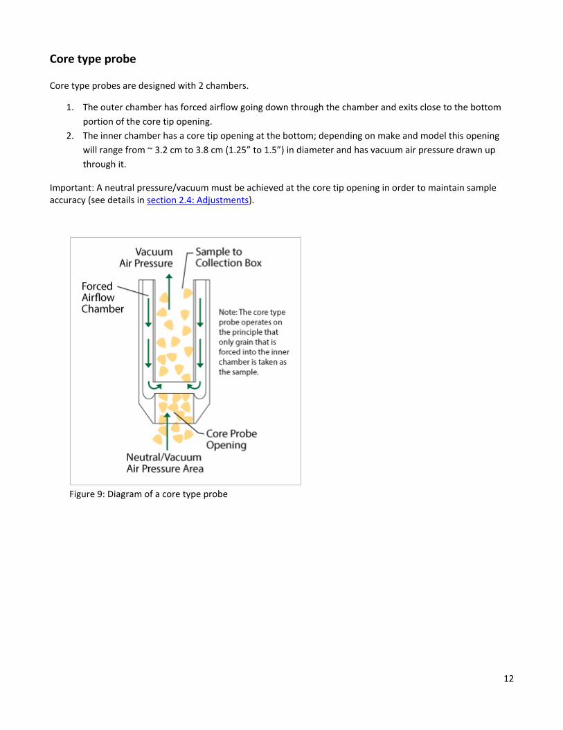
Core type probe
Core type probes are designed with 2 chambers.
1. The outer chamber has forced airflow going down through the chamber and exits close to the bottom portion of the core tip opening.
2. The inner chamber has a core tip opening at the bottom; depending on make and model this opening will range from ~ 3.2 cm to 3.8 cm (1.25” to 1.5”) in diameter and has vacuum air pressure drawn up through it.
Important: A neutral pressure/vacuum must be achieved at the core tip opening in order to maintain sample accuracy (see details in section 2.4: Adjustments).
Figure 9: Diagram of a core type probe
13
The length of the probe selected in combination with the boom’s telescopic extension should enable the operator to reach the bottom of each conveyance to be sampled. Probes are available in various lengths from the manufacturers, ranging from 5’ to 9’.
The operating radius of truck probes have various ranges but are limited. The reach of the probe must enable the operator to follow the recommended probing patterns for each conveyance. If the truck probe cannot reach all areas to be sampled, reposition the conveyance being sampled.
Sampling with a probe that does not reach the maximum depth of the conveyance and/or not following the recommended probing pattern increases sampling extraction error and the risk of collecting a sample that does not accurately represent the lot.
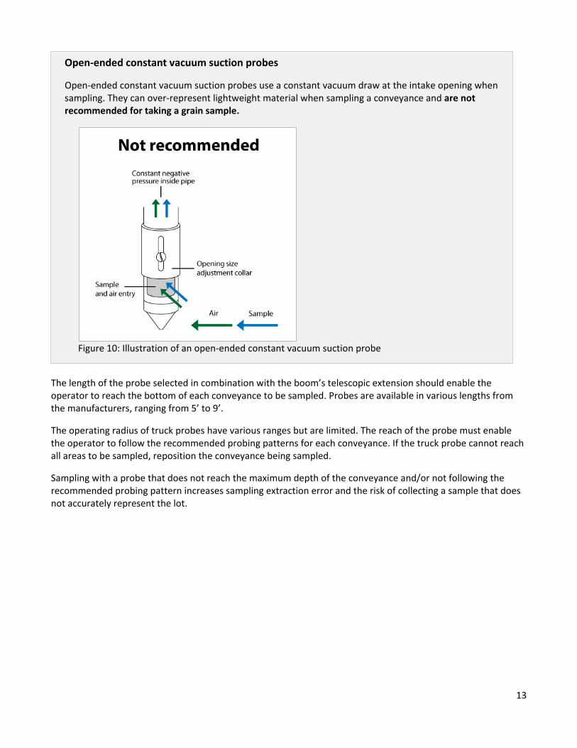
Open-ended constant vacuum suction probes
Open-ended constant vacuum suction probes use a constant vacuum draw at the intake opening when sampling. They can over-represent lightweight material when sampling a conveyance and are not recommended for taking a grain sample.
Figure 10: Illustration of an open-ended constant vacuum suction probe

14
Figure 11: Diagram of operating radius of a truck probe
Figure 12: Recommended truck probe sampling patterns
Truck probes with telescopic booms can generally extend the probe out to a maximum reach of ~ 17’ from the supporting structure.

15
Figure 13: Illustration of the range of motion of a telescopic boom for grain sampling
The vacuum and forced airflow system(s) are an integral part of the sampling and sample delivery systems. These components must have the capacity required to effectively draw a sample with the selected type of pneumatic truck probe and allow the sample to travel through the entire delivery system to a sample collector with minimal impact on the sample. Manufacturers will recommend specific makes and models of vacuum and forced airflow systems based on the installation configuration of each system. For a description of sample delivery lines, see section 2.2: Installation.
There are various makes and models of sample collection units. The vacuum system installation will determine the required type. The sample collection boxes require airtight discharge gates and should be installed in the inspection office.
Sample delivery systems utilizing a vacuum pump with a cyclone will not require a sample collection box with a separation screen inside. The cyclone allows the vacuum air pressure to exhaust while allowing the sampled grain to decelerate and transition to the sample collection unit.

16
Figure 14: Air supply and vacuum unit Figure 15: Pneumatic vacuum unit Figure 16: Sample collector using a vacuum pump with a cyclone
Sample delivery systems installed with only a vacuum pump will require a sample collection box with a separation screen inside. The separation screen allows the vacuum air pressure to pass through the screen and exhaust out while holding the sampled material on the intake side of the screen.
Figure 17: Sample collection box with separation screen

17
2.4 Adjustments
Compartment type probes
Compartment type probes are designed with 3 chambers. The first chamber is of neutral air pressure when sampling. The second chamber has an air intake/vent located at the top of the chamber/probe, allowing air to be drawn into the chamber as needed. The second and third chamber have a vacuum air pressure to draw the sample from the second chamber, through the third chamber and to the inspection office. Manufacturers will recommend specific makes and models of vacuum systems based on the installation configuration for each system, as there is no forced airflow requirement or adjustment for these types of probes.
Figure 18: Diagram of air intake/vent locations on a compartment type probe
Core type probes
Core type probes are designed with 2 chambers; the outer chamber has forced airflow travelling through it to the bottom portion of the core tip opening, and the inner chamber has vacuum air pressure drawn up through from the core tip opening. In order to achieve a neutral/vacuum pressure at the sample entry point of the core tip opening of the probe, the forced airflow going through the outer chamber must be controlled. To control this, the core probe is manufactured with one or more air adjustment relief holes. Some manufacturers also include air adjustment relief holes on the air supply motor assembly.
18
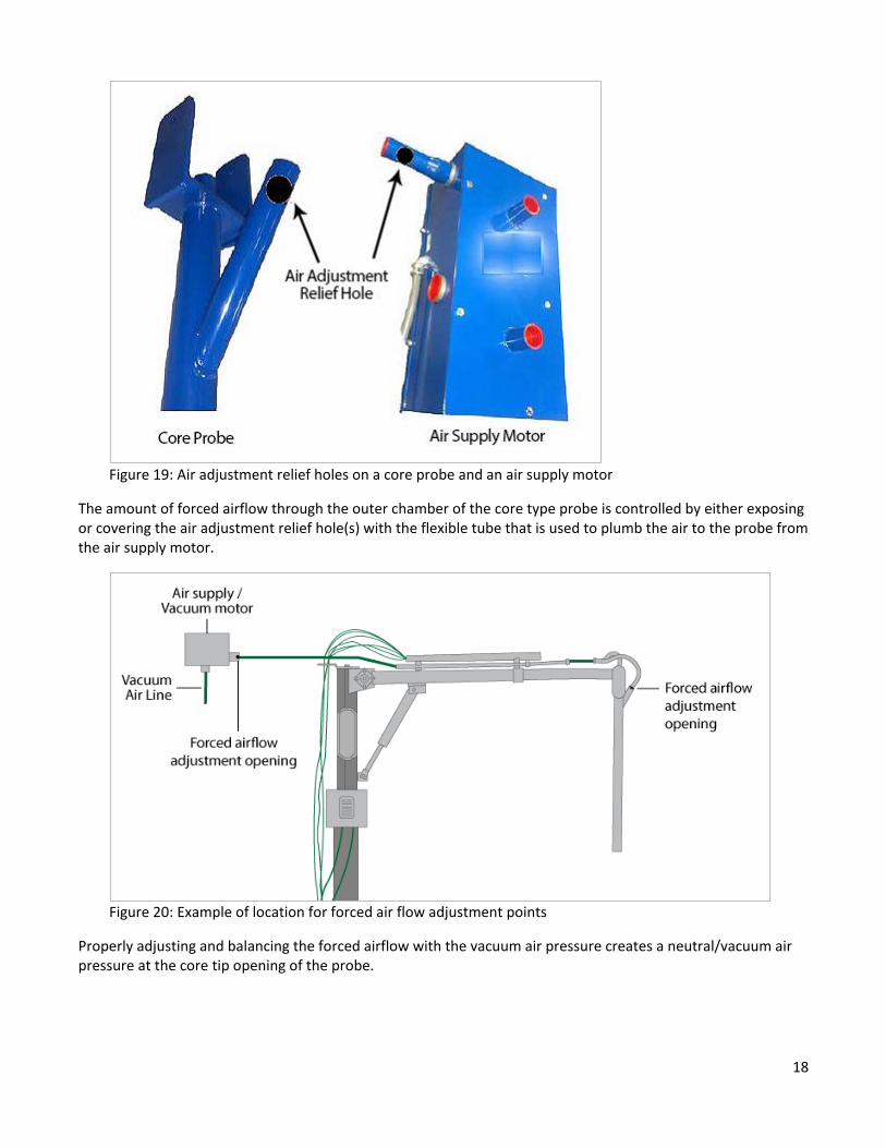
Figure 19: Air adjustment relief holes on a core probe and an air supply motor
The amount of forced airflow through the outer chamber of the core type probe is controlled by either exposing or covering the air adjustment relief hole(s) with the flexible tube that is used to plumb the air to the probe from the air supply motor.
Figure 20: Example of location for forced air flow adjustment points
Properly adjusting and balancing the forced airflow with the vacuum air pressure creates a neutral/vacuum air pressure at the core tip opening of the probe.

19
Figure 21: Illustration of air pressure in a core type probe
Follow these steps to determine if the adjustment(s) and air pressure balance are correct:
1. Position the pneumatic truck probe system so they are operating with the bottom of the probe positioned at an accessible height.
2. Place a piece of lightweight paper so it completely covers the core tip opening of the probe. - If the paper is blown away from the opening, there is too much forced airflow pressure. Expose the
air adjustment relief holes more to create a neutral/vacuum air pressure at the tip opening. - If the paper is being sucked into the opening, there is not enough forced airflow pressure. Cover the
air adjustment relief holes more to create a neutral/vacuum air pressure at the tip opening. - If the paper holds to the core tip opening by itself without being sucked in or blown away, the air
pressures are considered balanced.

20
Sampling problems caused by improperly adjusted forced air or excessive vacuum pressure
Figure 22: Illustration of airflow in a core type probe
• Inadequate/low forced airflow causes the air pressure at the core tip opening to have excess vacuum pressure, which could lead to over-representation of lightweight material by selecting more dust, small seeds or broken grain from the surrounding grain in the conveyance.
• Excessive vacuum pressure within the sampling apparatus and sample delivery system could impact the composition of the primary sample, such as increasing the amount of CCFM in corn.
Figure 23: Illustration of air movement in a core type probe
• Excess/high forced airflow causes the air pressure at the core tip opening to have excess forced airflow pressure, which could lead to under-representation of lightweight material by not allowing the selection of that material from the surrounding grain in the conveyance.
Manufacturers recommend that the air pressure at the core tip opening be checked at least once a month. Air supply and vacuum units will weaken over time; evaluate them as prescribed by the manufacturer.

21
2.5 Operation
• Ensure staff are trained in the proper use of the equipment in accordance with the manufacturer’s operating manual.
• Follow recommended probing patterns of conveyances and extract a sample from the entire depth of each conveyance to ensure a good representation of the conveyance has been sampled.
• Conveyances with shallow loads may need to have additional probes taken to obtain enough sample for inspection purposes.
• Draw additional probes in a representative manner (e.g. one area of a truck lot shall not be probed twice unless the entire truck is probed twice).
• Exercise extreme care when inserting the probe to prevent damage to the sides or bottom of the conveyance.
• During sampling operations, monitor the sample collection and delivery system for possible malfunctions.
• After all samples are drawn from the conveyance, check to ensure the sample delivery system and sample collection box are empty before sampling another conveyance.
Operating instructions for a compartment type probe
1. The operator manoeuvers the probe vertically downward into the load. This type of probe operates on the principle that only grain that flows via gravity into the first chamber compartments are taken as the sample.
2. Once at full depth the operator will then mechanically rotate the inner tube on the first chamber to the open position.
3. Material will then flow via gravity into the individual sample compartments within the first chamber; sufficient time is required for the compartments to fill and will depend on grain type and dockage content.
4. The operator will mechanically rotate the inner tube to the closed position. 5. The sampled material will then flow via gravity from the back of the first chamber into the second
chamber. 6. During the probe’s retraction or while the probe is still in the load, the sampled material is
pneumatically drawn from the bottom of the second chamber up through the third chamber and delivered to a sample collector in the inspection office.

22
Material flows into first chamber Sampled material transitions from
first to second chamber Sampled material transitions from second to third chamber
Figure 24: Illustration of the use of a compartment type probe
Operating instructions for a core type probe
1. The operator manoeuvers the probe vertically downward into the load. This type of probe operates on the principle that only grain that is forced into the inner chamber is taken as the sample.
2. When the product has reached the inner sample chamber at the core tip opening, it mixes with the air that is being forced down through the outer chamber of the probe.
3. The sampled material is then pulled away through the inner chamber via vacuum draw to a sample collector in the inspection office.
Illustration of core type probe and opening
Sampled material drawn up through inner chamber
Figure 25: Illustration of use of a core type probe
23
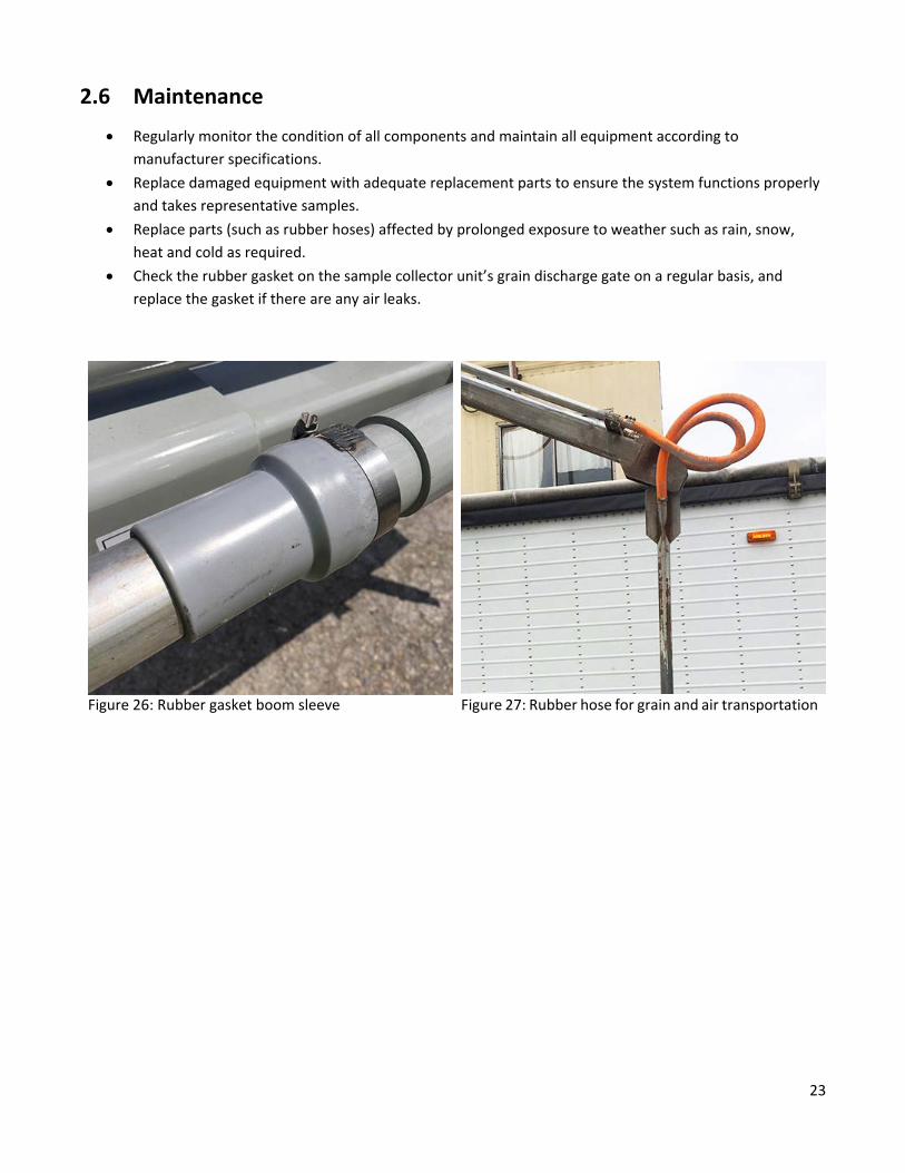
2.6 Maintenance
• Regularly monitor the condition of all components and maintain all equipment according to manufacturer specifications.
• Replace damaged equipment with adequate replacement parts to ensure the system functions properly and takes representative samples.
• Replace parts (such as rubber hoses) affected by prolonged exposure to weather such as rain, snow, heat and cold as required.
• Check the rubber gasket on the sample collector unit’s grain discharge gate on a regular basis, and replace the gasket if there are any air leaks.
Figure 26: Rubber gasket boom sleeve Figure 27: Rubber hose for grain and air transportation

24
Chapter 3: Manual stream sampling 3.1 Overview Sampling must be done in an area where the entire grain stream is accessible. Follow all safety precautions when sampling from a grain stream or near a moving conveyor. Draw samples from the grain stream at regularly timed intervals from the start to the finish of the grain transfer.
This section describes equipment and methods used for manual sampling under these conditions.
3.2 Hand scoops The hand scoop is a sampling device that consists of a handle constructed of rigid material and a sample collector with a minimum capacity of 50 grams, but less than 200 grams.
The intervals between individual scoop samples must be the same to ensure the samples are representative of the entire lot of grain. The length of interval should take into account:
• the amount of grain being sampled • the size of grain scoop you are using • how much sample is needed for grading or testing purposes
The larger the auger being used on farm or the smaller the load of grain, the shorter the interval should be. Using short, consistent intervals and taking many individual scoop samples will make the final composite sample more accurate.
Sample size is consistent when using any of the cup designs illustrated above
Sample size can be variable if using this type of scoop, therefore it’s unsuitable for obtaining a consistent sample size.
Figure 28: Examples of acceptable and unacceptable sampling scoops
When taking scoop samples:
• use the same grain scoop to take every sample • make sure you take enough samples to fill one 20 L pail to at least three-quarters full

25
3.3 Methods for stream sampling 1. Insert the sampling tool into the stream at alternating points across the stream (left, middle, right) for
each sampling action. 2. When sampling from a falling stream (tailgate or hopper bottom), place the scoop into the flow of
product upside down. 3. Rotate the scoop 180 degrees to fill, and then pull the scoop out of the product flow.
Manual sampling over an open pit
When sampling grain over an open pit, be careful to ensure the pit is not “choked.” This can limit the grain’s ability to “free fall” and prevent you from accessing the entire flow of grain.
Figure 29: Manual stream sampling over an open pit
Figure 30: Sampling points for manual stream sampling
26
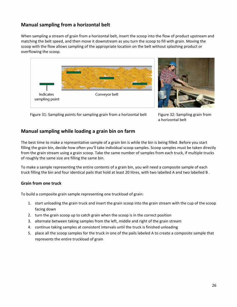
Manual sampling from a horizontal belt
When sampling a stream of grain from a horizontal belt, insert the scoop into the flow of product upstream and matching the belt speed, and then move it downstream as you turn the scoop to fill with grain. Moving the scoop with the flow allows sampling of the appropriate location on the belt without splashing product or overflowing the scoop.
Figure 31: Sampling points for sampling grain from a horizontal belt Figure 32: Sampling grain from a horizontal belt
Manual sampling while loading a grain bin on farm
The best time to make a representative sample of a grain bin is while the bin is being filled. Before you start filling the grain bin, decide how often you’ll take individual scoop samples. Scoop samples must be taken directly from the grain stream using a grain scoop. Take the same number of samples from each truck, if multiple trucks of roughly the same size are filling the same bin.
To make a sample representing the entire contents of a grain bin, you will need a composite sample of each truck filling the bin and four identical pails that hold at least 20 litres, with two labelled A and two labelled B .
Grain from one truck
To build a composite grain sample representing one truckload of grain:
1. start unloading the grain truck and insert the grain scoop into the grain stream with the cup of the scoop facing down
2. turn the grain scoop up to catch grain when the scoop is in the correct position 3. alternate between taking samples from the left, middle and right of the grain stream 4. continue taking samples at consistent intervals until the truck is finished unloading 5. place all the scoop samples for the truck in one of the pails labeled A to create a composite sample that
represents the entire truckload of grain

27
Grain from multiple trucks
Large grain bins may be filled by multiple trucks. To prepare a composite sample that represents more than one truckload of grain:
1. determine how much sample you will need from each truck to fill pail A to three-quarters full 2. follow the procedure to make a composite sample for each truck 3. reduce the composite sample from each truck to the desired quantity using the procedure to reduce a
composite sample 4. combine all the reduced samples in one pail labelled A 5. mix the combined samples in pail A thoroughly by hand
Pail A now contains a composite sample that represents the contents of your entire grain bin.
Figure 33: Diagram of representative grain sampling steps
Representative grain sampling steps
1. Primary samples are taken from throughout the bulk of each truckload of grain going into the bin 2. The primary samples from each truck are combined to make composite samples representing each
truckload of grain 3. The truck samples are reduced 4. The reduced samples representing all the truckloads of grain going into the bin are combined 5. The composite sample represents the contents of the entire grain bin 6. The composite sample is reduced and sealed in containers labelled to show the bin each sample
represents

28
Chapter 4: Manual sampling of static grain in truck and railcar conveyances 4.1 Overview Grain may be manually sampled when conveyed in trucks and railcars. The double sleeve trier is used to sample grain stored in these conveyances. Follow all safety precautions when sampling from these conveyances. Draw samples from these conveyances in prescribed probing patterns and reach the maximum depth of the conveyance.
Sampling with a double sleeve trier that does not reach the maximum depth of the conveyance and/or not following the recommended probing pattern increases sampling extraction error and the risk of collecting a sample that does not accurately represent the lot.
Recommended equipment and methods used for manual sampling of static grain are described in this chapter.
4.2 Double sleeve trier The double sleeve trier is typically constructed of brass or aluminium, and is available in varying lengths. It consists of 2 tubes, one inside the other. It can be used to sample static lots that are contained in sacks (bags) or totes, or lots that are in bulk provided the trier has sufficient length to reach to the bottom of the conveyance being sampled. The aperture must be a minimum of 19 mm (0.75“) in width.
Types of double sleeve triers
Compartmented Compartmented double sleeve triers have an inner tube that is divided into compartments. The outer tube has slots that match the compartment openings of the inner tube. When the tubes are aligned, grain flows into the compartments. The sample can only be discharged into a long trough or drop sheet. However, this type can make the sampling process cumbersome.
Open-throat Open-throat double sleeve triers have an inner tube that is open, as is the probe handle. This feature allows the sample to be poured from the probe directly into the sample container. However, open-throat probes tend to draw more of the sample from the top portion of the grain in the lot compared to the compartmented probe. Therefore, the composition of a sample obtained with an open-throat probe may differ slightly from that of a sample drawn with a compartmented probe. A design to address this issue features apertures that open in sequence, starting at the bottom, when turned to open. This design addresses the influence of grain pressure that allows more grain to flow into the top of the probe when sampling vertically.
Figure 34: Illustration of an open-throat double sleeve trier
29
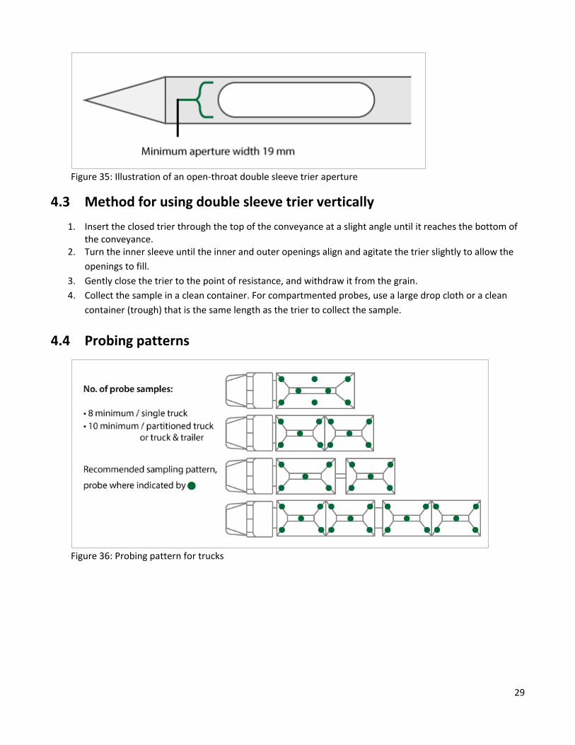
Figure 35: Illustration of an open-throat double sleeve trier aperture
4.3 Method for using double sleeve trier vertically 1. Insert the closed trier through the top of the conveyance at a slight angle until it reaches the bottom of
the conveyance.2. Turn the inner sleeve until the inner and outer openings align and agitate the trier slightly to allow the
openings to fill.3. Gently close the trier to the point of resistance, and withdraw it from the grain.4. Collect the sample in a clean container. For compartmented probes, use a large drop cloth or a clean
container (trough) that is the same length as the trier to collect the sample.
4.4 Probing patterns
Figure 36: Probing pattern for trucks

30
Figure 37: Probing pattern for railcars

31
Chapter 5: Reducing your composite grain sample 5.1 Overview Use the equipment and steps specified below to mix and reduce your composite sample into smaller samples. This will help ensure your samples are representative of the grain they were taken from and make the samples easier to handle and store. Keep in mind that you may need multiple samples for different purposes.
5.2 Boerner-type divider A Boerner-type divider is a gravity-operated dividing apparatus that separates a grain sample into 2 smaller equal portions. The sample is placed in the upper hopper and released by opening the valve in the hopper throat. The sample flows downward and is evenly dispersed over a cone with evenly spaced separations. The divided sample is then directed into 2 grain streams, which empty into 2 collecting pans at the bottom.
The following are requirements of the Canadian Grain Commission’s Official Grain Grading Guide and the Canada Grain Regulations.
• Official and unofficial samples used for dockage assessment and grading purposes shall be at least 1 kg.
Grading is done on representative samples that have been cleaned and then divided down using a Boerner-type divider.
Figure 38: Boerner-type divider

32
Procedure to divide a sample using a Boerner-type divider
1. Clean the divider and collection pans.2. Close the valve at the bottom of the hopper and place a collecting pan under each of the 2 outlets.3. Pour the grain into the hopper.4. Open the valve quickly. The grain will fall by gravity over the cone and will be evenly distributed through
the channels and spaces. The grain is divided into 2 halves, with each part being collected in one of the 2collecting pans.
5. To mix the grain, take the collecting pans and repeat steps 2 to 4 at least once for free-flowing grain andat least twice for chaffy grain.
6. To reduce a sample, repeat steps 2 to 4. This will result in half of the sample in each collecting pan.Always use the collecting pan from the same side.
5.3 Sample dividing with pails To divide a sample on a farm when a Boerner-type divider is not available, use this procedure to reduce your composite sample into a smaller sample that’s still representative of the grain in the bin. This will make the sample easier to handle and store. Keep in mind that you may need multiple samples for different purposes.
The Canadian Grain Commission’s Official Grain Grading Guide requires that unofficial samples used for dockage assessment and grading purposes shall be at least 1 kg.
To reduce a composite sample, you will need 3 pails: 1 pail labelled A, 1 pail labelled B and 1 pail labelled C.
1. Place the sample you’re dividing into pail A and 2. Place the empty pails labelled B and C side by sideand touching on a level surface.mix thoroughly by hand.

33
3. Pour the contents of pail A at the point where thepails touch, ensuring that half the stream flows into each pail B and pail C.
4. Pour the pail labelled B back into pail A.
5. Pour the contents of pail C back into the bin or truck in which it came from.
6. Repeat the process with the remaining sampleuntil you have the amount you need.
7. Place the final composite sample or samples insealed containers and label each container toshow the bin it represents.

34
Contact us Please direct any comments, questions or concerns regarding the content of this guide to:
Phone (toll free): 1-800-853-6705 TTY: 1-866-317-4289 Email: [email protected]