guide to infusion pump testing usa by rigel medical
DESCRIPTION
An Introduction to Infusion Pump Testing by Rigel Medical.TRANSCRIPT

Innovating Together
An introduction toInfusion Pump Testing
Rigel Medical, Seaward Group USA,6304 Benjamin Road, Suite 506,Tampa, Florida, 33634, United States
Tel: 813-886-2775 Email: [email protected]: rigelmedical.com/usa
Version 1.0 - 2014
Part of

1
Contents
Foreword 2
1 Introduction 2
2 Introduction and History of Infusion 3
2.1 Infusion Circuit 5
3 Types of Infusion 5
3.1 Elastomeric Pumps 6
3.2 Gravity Controllers 7
3.3 Syringe Drivers 7
3.4 Volumetric Pump 8
3.5 Patient Controlled Analgesia (PCA) Pump 8
3.6 Ambulatory Pumps 9
4 Infusion Characteristics 9
5 Problems Associated with Infusion 10
5.1 Air Embolism 11
5.2 Free Flow or Siphonage 11
5.3 Occlusion 11
5.4 Bolus 12
5.5 Vein Closing After Infusion 12
5.6 Infiltration or Tissuing 12
6 Testing Infusion Devices 13
6.1 Introduction 13
6.2 Volume/Flow Rate 14
6.2.1 Cylinders and Burette 14
6.2.2 Weighing Scales 15
6.2.3 Vernier Calipers/Dial Gauges 16
6.2.4 Electronic Devices 16
6.3 Occlusion and Alarm Pressure 17
6.3.1 Analogue Pressure/Force Gauge 17
6.3.2 Digital Pressure Meter 18
6.3.3 Electronic/Automatic Devices 19
6.4 PCA 19
6.4.1 Electronic/Automatic Analyzers 19
6.5 Trumpet Curve 19
7 Multi-Flo 21
7.1 Introduction 21
7.2 Testing Infusion Devices 22with the Multi-Flo
7.2.1 Syringe Driver Connection 22
7.2.2 Volumetric Pump Connection 22
7.2.3 Volume/Flow 22
7.2.4 Occlusion 23
7.2.5 PCA 24
8 Conclusion 24
9 References 25
Innova t ing Togethe r
Double yourtest capacitySave time, save money
Innovating Together
Introducing the NEW Rigel Multi-Flo Infusion Pump Analyzer
The only multi-channel infusion pump tester that providesinstant flow rate, volume and pressure measurementsfor unbeatable speed and accuracy.
Visit www.seaward-groupusa.com/multi-flo to find out moreOr call 813-886-2775
Part of
FREE Guideto Infusion
Pump TestingFor your free copy visit
www.seaward-groupusa.com/multi-flo
1 Introduction
It is estimated that 80% of hospitalised patientsreceive intravenous (IV) therapy and infusiondevices are used extensively in clinical settingsand patients’ homes as an essential tool forproviding perioperative care, critical care andpain management. The infusion of fluids uses avariety of designs providing the ability to feed,hydrate, medicate or replace blood loss [1-4].
An infusion system is the process by which aninfusion device delivers fluids, nutrition andmedication to a patient in a predetermined andconsistent manner. They are capable ofdelivering medication such as insulin or
2 3
rigelmedical.com/usa
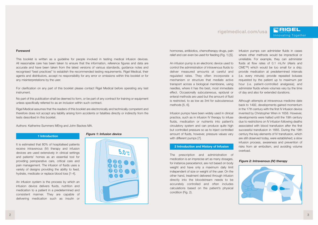
hormones, antibiotics, chemotherapy drugs, painrelief and can even be used for feeding (Fig. 1) [5].
An infusion pump is an electronic device used tocontrol the administration of intravenous fluids todeliver measured amounts at careful andregulated rates. They often incorporate amechanism or structure that mediate activetransport across a biological membrane, usingneedles, where it has the best, most immediateeffect. Occasionally subcutaneous, epidural orenteral methods are used but the amount of fluidis restricted, to as low as 3ml for subcutaneousmethods [5, 6].
Infusion pumps have been widely used in clinicalpractice, such as in infusion IV therapy to infusefluids, medication or nutrients into patient’scirculatory system and can produce quite highbut controlled pressure so as to inject controlledamount of fluids, however, pressure values varywith different pumps [7].
2 Introduction and History of Infusion
The prescription and administration ofmedication is an imprecise art as many dosages,for instance paracetamol, are not based on bodyweight and have only a maximum daily limitindependent of size or weight of the user. On theother hand, treatment delivered through infusiondirectly into the bloodstream needs to beaccurately controlled and often includescalculations based on the patient’s physicalcondition (Fig. 2).
Infusion pumps can administer fluids in caseswhere other methods would be impractical orunreliable. For example, they can administerfluids at flow rates of 0.1 mL/hr (Alaris andCME™) which would be too small for a drip;provide medication at predetermined intervals(i.e. every minute); provide repeated bolusesrequested by the patient up to maximum perhour (i.e. patient-controlled analgesia); andadminister fluids where volumes vary by the timeof day and also for extended durations.
Although attempts at intravenous medicine dateback to 1492, developments gained momentumin the 17th century with the first IV infusion deviceinvented by Christopher Wren in 1658. However,developments were halted until the 19th centurydue to restrictions on IV infusion following deathsassociated with blood transfusion after the firstsuccessful transfusion in 1665. During the 19thcentury the key elements of IV transfusion, whichare still observed today, were established; a slowinfusion process, awareness and prevention ofrisks from air embolism, and avoiding volumeoverload.
Innova t ing Togethe r
Foreword
This booklet is written as a guideline for people involved in testing medical infusion devices.All reasonable care has been taken to ensure that the information, reference figures and data areaccurate and have been taken from the latest versions of various standards, guidance notes andrecognised “best practices” to establish the recommended testing requirements. Rigel Medical, theiragents and distributors, accept no responsibility for any error or omissions within this booklet or forany misinterpretations by the user.
For clarification on any part of this booklet please contact Rigel Medical before operating any testinstrument.
No part of this publication shall be deemed to form, or be part of any contract for training or equipmentunless specifically referred to as an inclusion within such contract.
Rigel Medical assumes that the readers of this booklet are electronically and technically competent andtherefore does not accept any liability arising form accidents or fatalities directly or indirectly from thetests described in this booklet.
Authors: Katherine Summers MEng and John Backes MA.
Figure 1: Infusion device
Figure 2: Intravenous (IV) therapy
One of the major developments in infusionpumps was the invention in the early 1970s of awearable pump now known as the ambulatorypump by Dean Kamen, which enabled patientmobility during treatment [5].
There are many different types of infusion pumps,which are used for a variety of purposes and in avariety of environments; from simple gravitycontrollers which use a clamping action to varythe flow with the force of gravity, volumetricpumps which employ a linear peristaltic pumpingmechanism and syringe pumps which work bypushing a plunger at a predetermined rate [4].
Occlusion is an obstruction or closure of apassageway or vessel. A blockage in infusiondevices causes pressure to build up which canreduce the flow and cause harm to the patient.Most infusion pumps have a pre-determinedocclusion pressure threshold See 5.3 [7], wherean alarm activates once the pressure exceedsthis limit. If the occlusion pressure alarm is settoo high, the harmful effects can be prolongedprior to alarm. Therefore testing the occlusionpressure is crucial to infusion pump safety.
Infusion pumps must be periodically tested byqualified personnel to determine whether theyare functioning properly [7]. There is a wide rangeof methods used to test the performance andaccuracy of infusion devices which vary inprocedure and equipment. However, the primaryaim is to accurately measure the delivery volumeand flow rate of the infusion device, checkocclusion alarms and determine that it is safe foruse.
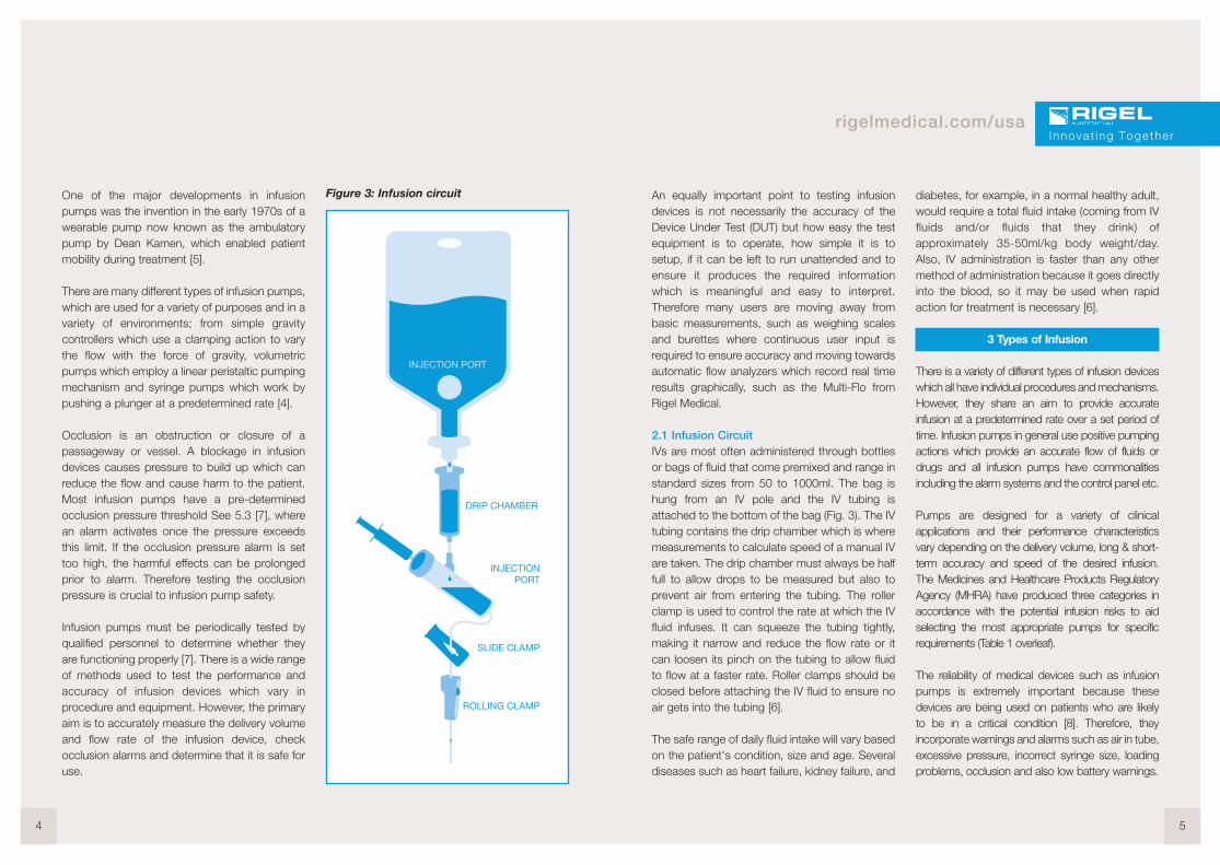
Figure 3: Infusion circuit
4 5
rigelmedical.com/usa
An equally important point to testing infusiondevices is not necessarily the accuracy of theDevice Under Test (DUT) but how easy the testequipment is to operate, how simple it is tosetup, if it can be left to run unattended and toensure it produces the required informationwhich is meaningful and easy to interpret.Therefore many users are moving away frombasic measurements, such as weighing scalesand burettes where continuous user input isrequired to ensure accuracy and moving towardsautomatic flow analyzers which record real timeresults graphically, such as the Multi-Flo fromRigel Medical.
2.1 Infusion CircuitIVs are most often administered through bottlesor bags of fluid that come premixed and range instandard sizes from 50 to 1000ml. The bag ishung from an IV pole and the IV tubing isattached to the bottom of the bag (Fig. 3). The IVtubing contains the drip chamber which is wheremeasurements to calculate speed of a manual IVare taken. The drip chamber must always be halffull to allow drops to be measured but also toprevent air from entering the tubing. The rollerclamp is used to control the rate at which the IVfluid infuses. It can squeeze the tubing tightly,making it narrow and reduce the flow rate or itcan loosen its pinch on the tubing to allow fluidto flow at a faster rate. Roller clamps should beclosed before attaching the IV fluid to ensure noair gets into the tubing [6].
The safe range of daily fluid intake will vary basedon the patient's condition, size and age. Severaldiseases such as heart failure, kidney failure, and
diabetes, for example, in a normal healthy adult,would require a total fluid intake (coming from IVfluids and/or fluids that they drink) ofapproximately 35-50ml/kg body weight/day.Also, IV administration is faster than any othermethod of administration because it goes directlyinto the blood, so it may be used when rapidaction for treatment is necessary [6].
3 Types of Infusion
There is a variety of different types of infusion deviceswhich all have individual procedures and mechanisms.However, they share an aim to provide accurateinfusion at a predetermined rate over a set period oftime. Infusion pumps in general use positive pumpingactions which provide an accurate flow of fluids ordrugs and all infusion pumps have commonalitiesincluding the alarm systems and the control panel etc.
Pumps are designed for a variety of clinicalapplications and their performance characteristicsvary depending on the delivery volume, long & short-term accuracy and speed of the desired infusion.The Medicines and Healthcare Products RegulatoryAgency (MHRA) have produced three categories inaccordance with the potential infusion risks to aidselecting the most appropriate pumps for specificrequirements (Table 1 overleaf).
The reliability of medical devices such as infusionpumps is extremely important because thesedevices are being used on patients who are likelyto be in a critical condition [8]. Therefore, theyincorporate warnings and alarms such as air in tube,excessive pressure, incorrect syringe size, loadingproblems, occlusion and also low battery warnings.
Innova t ing Togethe r

Table 1: MHRA Categories of Infusion
There are five main types of infusion with thesimplest device type being gravity controllers, whichemploy a clamping action to vary the flow of liquiddue to the force of gravity. More complex systemsuse a positive pumping action for infusion; a simpleversion being an elastomeric pump which has aballoon reservoir that contracts to deliver fluid ata constant rate. Volumetric pumps may employ alinear peristaltic pumping mechanism applied to theinfusion tubing or use a special cassette. Syringepumps work by pushing the plunger of adisposable syringe along at a predetermined rate.The type of pump used is dependent on thepatient’s needs such as the required volume andthe speed of the desired infusion [4].
3.1 Elastomeric PumpsElastomeric pumps, also called balloon pumps,are commonly used to administer liquid drugssuch as local anesthetics or antibiotics. Fluid isheld in a stretchable balloon reservoir andpressure from the elastic walls drive the fluiddelivery with relatively consistent pressure untilnear the end of the infusion, which then spikesresulting in increased flow rate. The flowrestrictor, usually a glass capillary or steelcannula, is molded into the tubing or situatedwithin the reservoir to control the accuracy of theflow rate (Fig. 4).
Elastomeric pumps run independently withoutany electronics and are not gravity driven whichmakes them maintenance free and typicallysingle-use. They are known for their reliability andaccurate flow rate and drugs can be delivered
6 7
rigelmedical.com/usa
over a long period of time, up to seven days,making it ideal for outpatients or patients thatrequire mobility. However, the pump’s placementeither above or below the patient will affect theflow rate.
Figure 4: Elastomeric Pump
3.2 Gravity ControllersFor gravity controlled pumps the IV bag issituated higher than the patient’s heart and fluidis gravity fed towards the patient using a rollerclamp to control the flow. Timing how fast thedrops fall through the tube drip chamber enablesa flow rate to be determined and the greater thebag height, the quicker the flow rate in millilitersper drop (mL/drop). Each 300mm increase inheight of the IV bag, produces approximately25mmHg of pressure. This method of infusion isoften used in Emergency Rooms, by paramedicsin ambulances and by athletic trainers [4].
3.3 Syringe DriversSyringe drivers utilise an electronically controlled,electric motor to slowly depress the plastic syringepiston/plunger to drive the fluid into the patient ata predetermined rate. The electronics control thespeed (flow rate), distance (volume infused) andthe force (pressure) that the syringe plunger ispushed (Fig. 5). The operator must use the correctmodel and size of syringe, ensure it is correctlypositioned and frequently monitor the delivery tomaintain the expected drug dosage up to100ml offluid at flow rates between 0.1 to 100mL/hr.
Innova t ing Togethe r
TherapyCategory
Therapy Description Patient Group Critical Performance Parameters
A Drugs with narrowtherapeutic margin
Drugs with short half-life
Any infusion given toneonates
Any
Any
Neonates
Good long-term accuracyGood short-term accuracyRapid alarm after occlusionSmall occlusion bolusAble to detect very small air embolus (volumetric pumps only)Small flow rate incrementsGood bolus accuracyRapid start up time
B Drugs, other than thosewith a short half-life
TPN Fluid maintenanceTransfusions
Diamorphine
Any except neonates
Volume sensitive except neonates
Any except neonates
Good long-term accuracyAlarm after occlusionSmall occlusion bolusAble to detect small embolus (volumetric pumps only)Small flow rate incrementsBolus accuracy
C TPN Fluid maintenanceTransfusions
Any except volume sensitive orneonates
Long-term accuracyAlarm after occlusionSmall occlusion bolusAble to detect air embolus (volumetric pumps only)Incremental flow rates
Figure 5: Syringe pump
Syringe drivers are the preferred choice for lowervolumes and low flow rates and can infuse smallvolumes of fluid over an extended period of timewhile maintaining a constant rate. However,users should be aware that the flow delivered atthe start of any infusion might be less than thepredetermined value due to mechanical slackwhich must be taken up before a steady flow rateis achieved. At low flows it can be some timebefore any fluid is delivered to the patient.
3.4 Volumetric PumpThe volumetric infusion pump is the mostsophisticated type of pump which forces fluid intothe patient’s vein under pressure and resistance [6].The IV bag is situated higher than the pump andpatient and the pump utilises a linear peristalticaction or uses a special cassette, known as apiston cassette, to control the infusion fluid. A set ofrollers pinch the flexible tubing to push the fluidtowards the patient (Fig. 6). Volumetric pumps areused to administer up to 1000mL of fluid at flowrates between 0.1 to 1000mL/hr. However, thistype of pump is not considered accuratelyappropriate for the delivery of fluids at a rate lowerthan 5mL/hr.
Peristaltic action is a continuous rippling wavemotion which can be linear or rotary. The BaxterColleague™ pumps use a linear peristaltic pumpingaction and the rotary peristaltic action is mostcommonly used in feeding and Patient ControlledAnalgesic (PCA) pumps.
Cassette type pumps have a plunger mechanismbuilt into the tubing set where the stepper motordrives the motion. The cassette also has a valvewhich is timed to only open when the plunger is
pumping. This valve can sometimes be used as afree-flow mechanism. The Ivion Kids pumps usedthis type of pumping mechanism as do some PCApumps.
Figure 6: Volumetric pump
3.5 Patient Controlled Analgesia (PCA) PumpA PCA pump is a type of syringe driver that allowsthe patient, within specified limits, to control theirown drug delivery through a patient hand control,which when pressed, delivers a pre-set amount ofanalgesic drug, known as a Bolus (Fig. 7). Afterthe delivery of the bolus the pump will return tothe normal basal flow rate and refuse to deliveranother bolus until a defined time has passed,known as the lockout time, thus limiting thenumber of boluses allowed. The bolus size andlockout time, along with the constant basal druginfusion rate are pre-programmed by the clinician.
Figure 7: Patient controlled analgesia(PCA) pump
8 9
rigelmedical.com/usa
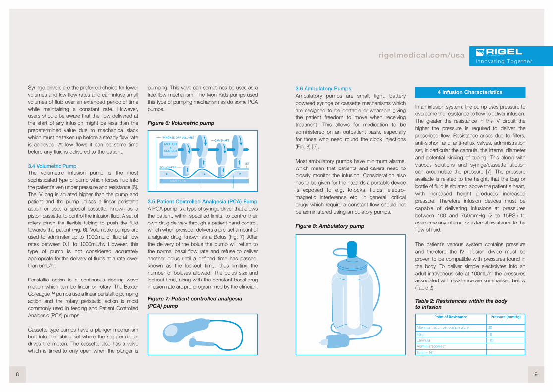
3.6 Ambulatory PumpsAmbulatory pumps are small, light, batterypowered syringe or cassette mechanisms whichare designed to be portable or wearable givingthe patient freedom to move when receivingtreatment. This allows for medication to beadministered on an outpatient basis, especiallyfor those who need round the clock injections(Fig. 8) [5].
Most ambulatory pumps have minimum alarms,which mean that patients and carers need toclosely monitor the infusion. Consideration alsohas to be given for the hazards a portable deviceis exposed to e.g. knocks, fluids, electro-magnetic interference etc. In general, criticaldrugs which require a constant flow should notbe administered using ambulatory pumps.
Figure 8: Ambulatory pump
4 Infusion Characteristics
In an infusion system, the pump uses pressure toovercome the resistance to flow to deliver infusion.The greater the resistance in the IV circuit thehigher the pressure is required to deliver theprescribed flow. Resistance arises due to filters,anti-siphon and anti-reflux valves, administrationset, in particular the cannula, the internal diameterand potential kinking of tubing. This along withviscous solutions and syringe/cassette stictioncan accumulate the pressure [7]. The pressureavailable is related to the height, that the bag orbottle of fluid is situated above the patient's heart,with increased height produces increasedpressure. Therefore infusion devices must becapable of delivering infusions at pressuresbetween 100 and 750mmHg (2 to 15PSI) toovercome any internal or external resistance to theflow of fluid.
The patient’s venous system contains pressureand therefore the IV infusion device must beproven to be compatible with pressures found inthe body. To deliver simple electrolytes into anadult intravenous site at 100mL/hr the pressuresassociated with resistance are summarised below(Table 2).
Table 2: Resistances within the bodyto infusion
I nnova t ing Togethe r
Point of Resistance Pressure (mmHg)
Maximum adult venous pressure 30
Filter 10
Cannula 100
Administration set 1
Total = 141
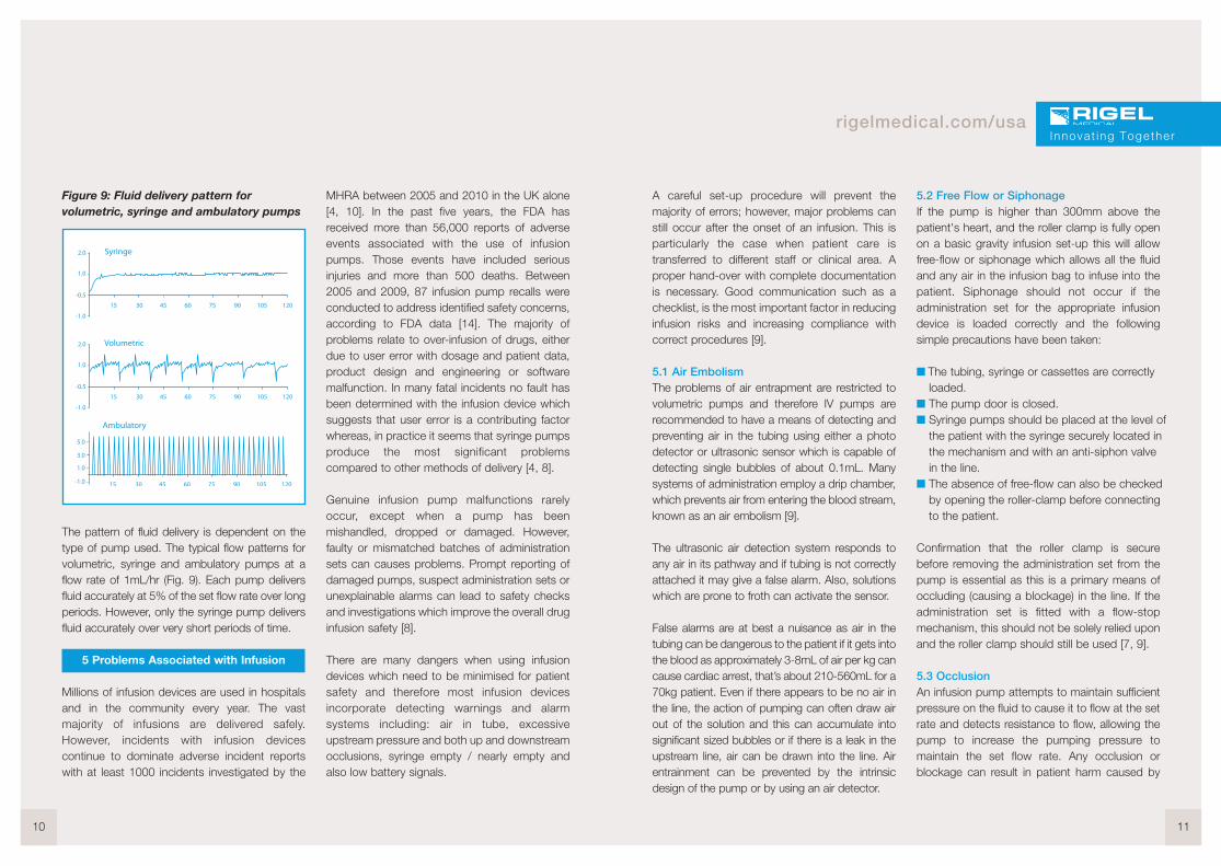
Figure 9: Fluid delivery pattern forvolumetric, syringe and ambulatory pumps
The pattern of fluid delivery is dependent on thetype of pump used. The typical flow patterns forvolumetric, syringe and ambulatory pumps at aflow rate of 1mL/hr (Fig. 9). Each pump deliversfluid accurately at 5% of the set flow rate over longperiods. However, only the syringe pump deliversfluid accurately over very short periods of time.
5 Problems Associated with Infusion
Millions of infusion devices are used in hospitalsand in the community every year. The vastmajority of infusions are delivered safely.However, incidents with infusion devicescontinue to dominate adverse incident reportswith at least 1000 incidents investigated by the
MHRA between 2005 and 2010 in the UK alone[4, 10]. In the past five years, the FDA hasreceived more than 56,000 reports of adverseevents associated with the use of infusionpumps. Those events have included seriousinjuries and more than 500 deaths. Between2005 and 2009, 87 infusion pump recalls wereconducted to address identified safety concerns,according to FDA data [14]. The majority ofproblems relate to over-infusion of drugs, eitherdue to user error with dosage and patient data,product design and engineering or softwaremalfunction. In many fatal incidents no fault hasbeen determined with the infusion device whichsuggests that user error is a contributing factorwhereas, in practice it seems that syringe pumpsproduce the most significant problemscompared to other methods of delivery [4, 8].
Genuine infusion pump malfunctions rarelyoccur, except when a pump has beenmishandled, dropped or damaged. However,faulty or mismatched batches of administrationsets can causes problems. Prompt reporting ofdamaged pumps, suspect administration sets orunexplainable alarms can lead to safety checksand investigations which improve the overall druginfusion safety [8].
There are many dangers when using infusiondevices which need to be minimised for patientsafety and therefore most infusion devicesincorporate detecting warnings and alarmsystems including: air in tube, excessiveupstream pressure and both up and downstreamocclusions, syringe empty / nearly empty andalso low battery signals.
10 11
rigelmedical.com/usa
A careful set-up procedure will prevent themajority of errors; however, major problems canstill occur after the onset of an infusion. This isparticularly the case when patient care istransferred to different staff or clinical area. Aproper hand-over with complete documentationis necessary. Good communication such as achecklist, is the most important factor in reducinginfusion risks and increasing compliance withcorrect procedures [9].
5.1 Air EmbolismThe problems of air entrapment are restricted tovolumetric pumps and therefore IV pumps arerecommended to have a means of detecting andpreventing air in the tubing using either a photodetector or ultrasonic sensor which is capable ofdetecting single bubbles of about 0.1mL. Manysystems of administration employ a drip chamber,which prevents air from entering the blood stream,known as an air embolism [9].
The ultrasonic air detection system responds toany air in its pathway and if tubing is not correctlyattached it may give a false alarm. Also, solutionswhich are prone to froth can activate the sensor.
False alarms are at best a nuisance as air in thetubing can be dangerous to the patient if it gets intothe blood as approximately 3-8mL of air per kg cancause cardiac arrest, that’s about 210-560mL for a70kg patient. Even if there appears to be no air inthe line, the action of pumping can often draw airout of the solution and this can accumulate intosignificant sized bubbles or if there is a leak in theupstream line, air can be drawn into the line. Airentrainment can be prevented by the intrinsicdesign of the pump or by using an air detector.
5.2 Free Flow or SiphonageIf the pump is higher than 300mm above thepatient's heart, and the roller clamp is fully openon a basic gravity infusion set-up this will allowfree-flow or siphonage which allows all the fluidand any air in the infusion bag to infuse into thepatient. Siphonage should not occur if theadministration set for the appropriate infusiondevice is loaded correctly and the followingsimple precautions have been taken:
� The tubing, syringe or cassettes are correctlyloaded.
� The pump door is closed.� Syringe pumps should be placed at the level of
the patient with the syringe securely located inthe mechanism and with an anti-siphon valvein the line.
� The absence of free-flow can also be checkedby opening the roller-clamp before connectingto the patient.
Confirmation that the roller clamp is securebefore removing the administration set from thepump is essential as this is a primary means ofoccluding (causing a blockage) in the line. If theadministration set is fitted with a flow-stopmechanism, this should not be solely relied uponand the roller clamp should still be used [7, 9].
5.3 OcclusionAn infusion pump attempts to maintain sufficientpressure on the fluid to cause it to flow at the setrate and detects resistance to flow, allowing thepump to increase the pumping pressure tomaintain the set flow rate. Any occlusion orblockage can result in patient harm caused by
Innova t ing Togethe r
increased pressure in the line and an interruptionto the therapy. This is typically due to a partial orcomplete block in the delivery tubing e.g. kinks inthe tube, clamp or tab closed; or in the cannulae.g. clotted off or a change in position. Occlusioncan cause an interruption to the delivery andeffectiveness of the therapy. Therefore, occlusionalarms are used to indicate when the pump isunable to sustain the set flow rate or whenpressure in the line increases, which is usually astall sensor on the IV pump stepper motor or apressure transducer within the line. Any blockagecan cause the pressure in the line to increasewhich causes the tubing to expand and if thepump detects an unacceptably high pressure,known as the occlusion limit, the pump’socclusion alarm will sound. Adult alarm settingsshould be approximately 150mmHg aboveworking pressure and therefore a default settingof 300mmHg is standard [7].
5.4 BolusA syringe that is placed into a pump whilstconnected to the patient is highly likely to deliveran infusion bolus. Syringes should always beinserted into pump mechanisms before beingattached to patients and the infusion line shouldbe temporarily disconnected. Even if the infusionset is left connected to the syringe driver orvolumetric pump during transfers, largealterations in the device height relative to thepatient may lead to over or under-infusionbecause of tubing compliance [7].
Once occlusion is cleared a sudden bolus willinfuse into the patient, which is the additionalfluid generated in the line during the occlusion.
This will cause a momentary raise in the fluid’sconcentration. The higher the occlusion alarm/pressure limit is set, the longer IV relatedproblems are allowed to develop before thealarm alerts staff of any issue and resulting in alarger bolus. Flow rate also affects alarmresponse time as higher flow rates result in morerapid alarm response than lower flow rates.
To prevent this bolus occurring, the pressure in thesystem should be reduced by temporarily openingthe system to air or disengaging the clamp on thesyringe plunger. Modern syringe drivers have anautomatic ‘back-off’ facility when occlusion isdetected which briefly draws back the plungerthus reducing the size of any bolus [7, 9].
5.5 Vein Closing After InfusionAll IV pumps have a ‘keep vein open’ (KVO)function which occurs when the time or volumeto be infused is reached and prevents theinfusion needle from clogging by continuing toinfuse a flow between 1 and 5mL/hr, which isalways a rate lower than the set infusion rate [7,9].
5.6 Infiltration or TissuingInfiltration or tissuing is the leakage of fluids as aresult of improper infusion and can be caused bypunctures of vein wall, dislodgement ofcatheter/needle cannula, inappropriate venous site,improper cannula size or excessive delivery rate.
Infiltrations can occur at pressure greater than100mmHg and pumps deliver infusions atpressures of 750mmHg (15PSI) to overcomefluid resistance which makes them capable of
12 13
rigelmedical.com/usa
producing extra-vascular patient damage. Tominimise this risk infusion pumps have adjustablepumping/occlusion pressure settings (normallytechnical settings), newer units incorporate usersettings.
A balance is required between setting thepumping pressure to overcome all baseline andintermittent resistance whilst preventing thepossibility of tissuing. Setting the pressure low, atbest causes nuisance occlusion alarms.
6 Testing Infusion Devices
6.1 IntroductionOptimal infusion is the ability of a device to reliablydeliver the prescribed dosage and volume to thepatient, at a pressure which overcomes allbaseline and intermittent resistance, whilstcausing no harm to the patient [10]. The reliabilityof infusion pumps is extremely important becausethese devices are used for patients who couldbe in a critical condition; also due to incidentsassociated with infusion devices there is a need toadequately validate the accuracy andperformance of such devices [7].
All tests carried out should mimic real lifesettings, as close as possible, which are carriedout by nursing staff when the system was initiallyset up. Hence, testing should reflect what themanufacturer recommends ensuring that theequipment is working within its specification. Theuser should always use the specification forreference when taking measurements and/or usethe test equipment recommended or specifiedby the manufacturer.
There is a variety of methods currently used totest infusion devices and determine theirperformance accuracy. They vary in procedureand equipment but fundamentally, the aim is tomeasure the accuracy of the delivery volume andflow rate over a range of time periods, typicallybetween 10 minutes and 1 hour.
Common flow measuring principles:1. Volumetric - Flow calculated after a certain
volume has been delivered. The greater thevolume over a certain time, the greater theflow.
2. Mass - Flow is calculated based ontemperature difference between two pointswithin the sensor, the greater the temperaturedifference the lower the flow.
3. Bubble tracking - Flow calculated based onthe displacement of an inserted airbubbleinto the flow sensor part. The greater thedisplacement, the greater the flow.
4. Pressure based - Flow is regulated within theflow sensor to a set line pressure. The greaterthe potential pressure built-up in the line, thegreater the flow rate.
5. Displacement of syringe plunger - Flow rate iscalculated based on volume displaced by thesyringe plunger over time. The syringe typeand volume are required to provide anaccurate calculation.
Occlusion and alarm pressures and also bolusdelivery must also be tested to maintain the
Innova t ing Togethe r

performance of the infusion device especially inPCA devices where the bolus is self-medicated.A visual inspection and electrical safety testshould also be considered to make sure allaspects of patient safety and instrument reliabilityare covered during the test procedure.
When looking at the accuracy of an infusionsystem the system must be looked at as a whole,and not just the pump or driver individually as theinaccuracies within the measuring device need tobe added to the accuracy limits of the DUT. Eventhough the infusion device itself may only have asmall percentage error; taking into account allpossible inaccuracies of the syringe used andother external equipment, including the tubingset, could increase the inaccuracy to 10%. Forexample, the diameter, length and elasticity ofthe tubing can provide greater inaccuracies thanthe pump itself, especially over time as thematerial’s properties change. Due to theseinaccuracies it is generally accepted that thetesting method and equipment used must be anorder of magnitude of 1/10th more accurate thanthe device being tested [8].
6.2 Volume/Flow RateThe most commonly used methods for measuringvolume or flow rate are direct volumetric; usingeither graduated cylinders or burettes; and,derived mass measurement using a measurementvessel and weighing scales. When using thesemethods it is recommended that only distilledwater be used to measure the total volumedelivered as the weight in grams is equivalent tothe weight in milliliters.
6.2.1 Cylinders and BuretteWhen using a direct volumetric method theestimated time is calculated prior to testing byfirst determining the rate per minute and then thedesired volume over the rate per minute, todetermine the time to reach the volume.
For example: q=V/t
When testing a pump with a flow rate of240mL/hr, the rate per minute = 240/60= 4mLper minute. If the desired measurement volume is20mL, the desired volume/ rate per minute =20/4 = 5 minutes. So, it would take 5 minutes toreach 20mL of volume with a flow rate of 240mL/hr.
The pump is set to run at the desired flow rateand the amount delivered into the measuringdevice is measured and the total time recorded,often using a stopwatch. The results are thenused to determine the accuracy of the systemand the average rate can be calculated as a totalvolume over total time (mL/hr).
Some technicians produce test rigs whichinclude a connection between the stopwatchand the pump so that when the pump finishesdelivering fluid the stopwatch automaticallystops. Otherwise the user must continuouslymonitor the test to record the volume at thedesired time.
Reading the volume from a measuring cylinderaccurately is difficult as the eye must be in linewith the lower level of the surface of the water,known as the meniscus, and the measuringcylinder must be placed on a level surface [12].
14 15
rigelmedical.com/usa
Also when using a measuring cylinder the unitgraduations must be considered which providesa degree of inaccuracies e.g. a 100mL cylinderwith 1mL graduation will therefore only beaccurate to ± 0.5mL. The total capacity of thecylinder must be considered not just the volumefilled (Fig. 10a).
Figure 10(a):Measuring cylinder 10(b): burette
Burettes are calibrated, marked in divisions, andare usually more accurate than measuringcylinders. The amount of liquid that is tappedfrom a burette can simply be read from theburette by checking the level of the meniscus
(Fig. 10b). A burette is particularly suitable formeasuring volumes less than 50mL with atolerance of 0.1cm3 [14]. Uncertainty in themeasurement of a 50mL burette is 0.1mLtherefore ± 0.2%. Adding this error to the typicalacceptable tolerances for a syringe driver of 2%will give the total inaccuracy of ± 2.2%. The totalinaccuracy needs to be checked against that ofthe manufacturer’s recommended limits to makesure that it is within allowable tolerances.
6.2.2 Weighing ScalesOne of the most accurate and simplest methodsto measure volume and flow rate is to use scalesto determine the weight or mass of the infusedliquid (Fig. 11). Scales can be calibrated toprovide extremely accurate results and are usefulfor measuring volumes as the weight of theempty cylinder can be "zeroed out" (tared) hencethe results are a direct reading of the weight ofthe fluid volume delivered based on theassumption that 1g is equivalent to 1mL of fluid(derived mass method).
Figure 11: Weighing scales
I nnova t ing Togethe r
The pump is set to deliver a specific volume at aspecified rate and the vessel is re-weighed at theend of the test. A stopwatch would be requiredto record the time. This method requires userinput to monitor the time and to maintainaccuracy. A percentage error can be calculatedfrom the figures obtained.
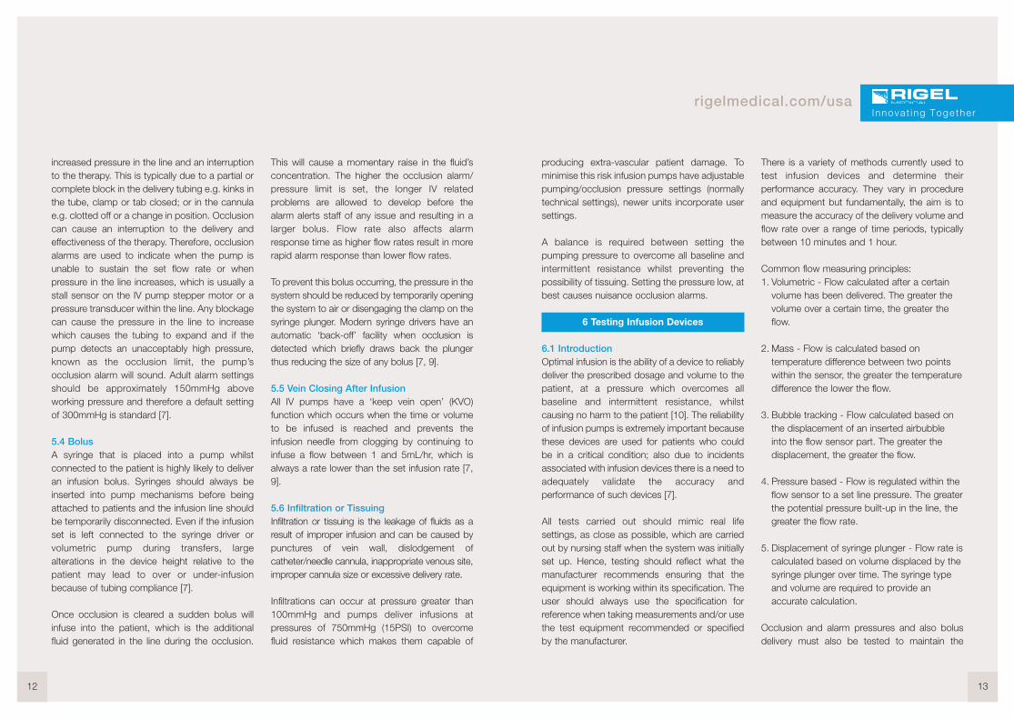
6.2.3 Vernier Calipers/Dial GaugesVernier calipers and dial gauges give a directreading of the distance measured with highaccuracy and precision. They are functionallyidentical, with varying ways of reading the result.Calipers are comprised of two jaws, oneattached to a fixed scale and the other attachedto a sliding scale. In order to measure an object’swidth, the object is simply placed between thecaliper’s jaws and then the distance between thejaws is read to an accuracy of 0.05mm (Fig. 12a)[11].
Dial gauges are a precision measurementcapable of producing extremely finemeasurement increments up to 0.001mm. Themeasurement inputs are transferred to the gaugevia a plunger or hinged lever and are availablewith either an analogue needle and dial indicatorsor digital liquid crystal displays (LCDs) (Fig. 12b)[10].
These methods are used to check the plungerstravel accuracy. Some pumps such as the Alaris(Carefusion) pumps come with a dedicated testset that uses a linear test gear and a stop watchto determine how far the plunger moves to checkincremental and overall time of delivery.
Figure 12(a):Vernier calipers 12(b): dial guage
6.2.4 Electronic DevicesAutomated analyzers allow the user to set up a testand the test will run unassisted thus allowing theuser to move away from the device during testing.Electronic analyzers provide real-time records ofthe delivery rate and volume allowing forcontinuous infusion device testing without constantsupervision. Analyzers provide continuous spotreadings which can then be graphed to providequick to read results; where problems andanomalies are easily visible. Electronic calibratedanalyzers provide automation for batch andmulti-channel testing with some analyzers havingup to 4 independent channels which can runsimultaneously, reducing overall test time whilemaintaining a good degree of accuracy andminimising user input and any errors associated.
16 17
rigelmedical.com/usa
These devices work by timing how long a smallinternal volume takes to fill and thereforemeasures the volumetric accuracy of the infusiondevice where accuracy is determined by themeasuring chamber accuracy and its resolution isdetermined by the chamber volume. It providesthe user with a method to obtain a quick check asto whether a pump is generally working. You cantest it over a range of flow-rates and time periodswith consistant accuracy [9]
6.3 Occlusion and Alarm PressureOcclusion is the interruption or ineffective therapyof infusion due to a blockage, momentaryclosure or obstruction of the passageway.Occlusion sensors can detect both upstreamand downstream restrictions and thedownstream occlusion sensor sensitivity can beadjusted to suit the needs of the patient/hospitalthrough the pump configurations.
Dynamic monitoring systems provide the abilityto monitor downstream pressure or resistanceallowing for rapid detection of full or partialblockages. To prevent nuisance alarms andinterruptions to therapy the initial occlusionpressure needs to be set above the systemsnormal running pressure.
Occlusion alarms are used to indicate when thepump is unable to sustain the set flow rate andtherefore pressure in the line begins to increase.This is typically due to a partial or complete blockin the delivery tubing e.g. kinks in the tube, clampor tab closed; or blockage signs in the cannulae.g. clotted off or a change in position.
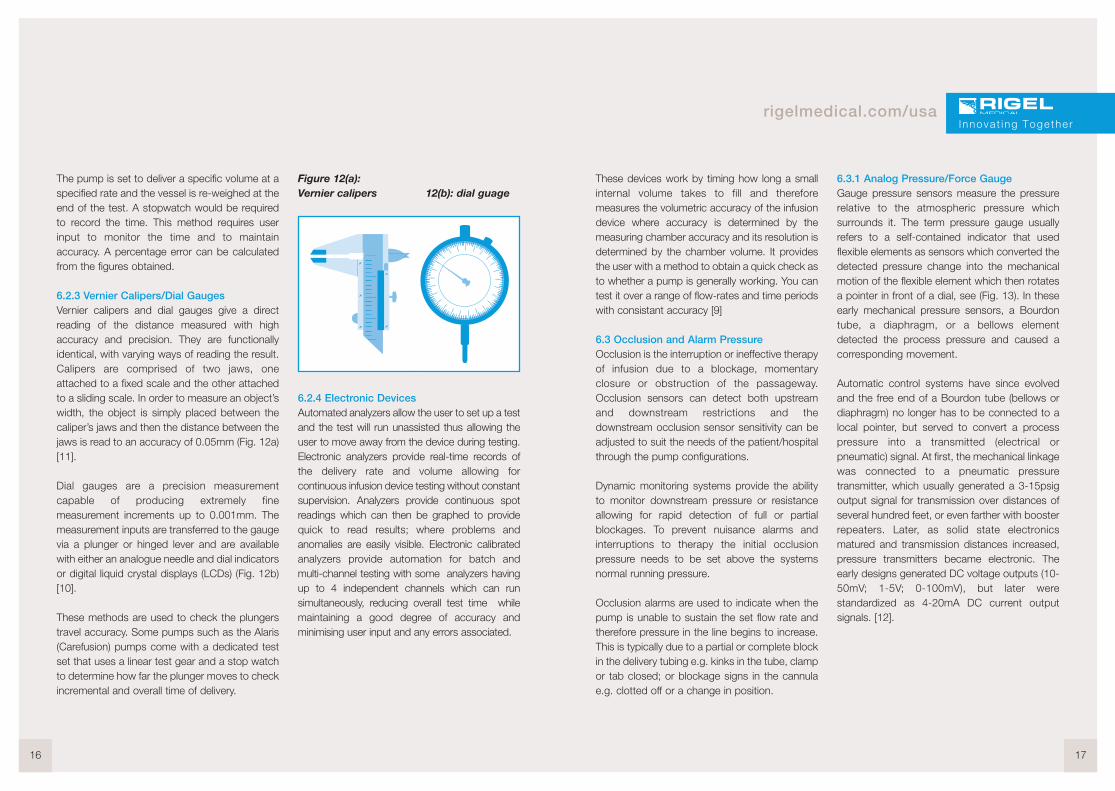
6.3.1 Analog Pressure/Force GaugeGauge pressure sensors measure the pressurerelative to the atmospheric pressure whichsurrounds it. The term pressure gauge usuallyrefers to a self-contained indicator that usedflexible elements as sensors which converted thedetected pressure change into the mechanicalmotion of the flexible element which then rotatesa pointer in front of a dial, see (Fig. 13). In theseearly mechanical pressure sensors, a Bourdontube, a diaphragm, or a bellows elementdetected the process pressure and caused acorresponding movement.
Automatic control systems have since evolvedand the free end of a Bourdon tube (bellows ordiaphragm) no longer has to be connected to alocal pointer, but served to convert a processpressure into a transmitted (electrical orpneumatic) signal. At first, the mechanical linkagewas connected to a pneumatic pressuretransmitter, which usually generated a 3-15psigoutput signal for transmission over distances ofseveral hundred feet, or even farther with boosterrepeaters. Later, as solid state electronicsmatured and transmission distances increased,pressure transmitters became electronic. Theearly designs generated DC voltage outputs (10-50mV; 1-5V; 0-100mV), but later werestandardized as 4-20mA DC current outputsignals. [12].
Innova t ing Togethe r
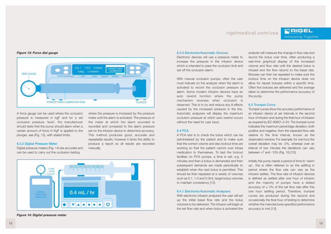
Figure 13: Force dial gauge
A force gauge can be used where the occlusionpressure is measured in kgF and for a setocclusion pressure ‘level’, the manufacturershould state that the pump should alarm when acertain amount of force in KgF is applied to theplunger, see (Fig. 13), with stated limits.
6.3.2 Digital Pressure MeterDigital pressure meters (Fig. 14) are accurate andcan be used to carry out the occlusion testing
where the pressure is increased by the pressuremeter until the alarm is activated. The pressure ofthe meter at which the alarm sounded isrecorded and compared to the alarm pressureset on the infusion device to determine accuracy.This method produces good, accurate andrepeatable results, however it lacks the ability toproduce a report so all results are recordedmanually.
18 19
rigelmedical.com/usa
6.3.3 Electronic/Automatic DevicesElectronic devices will use a pressure meter toincrease the pressure in the infusion devicewhich is intended to pass the occlusion limit andset off the occlusion alarm.
With manual occlusion pumps, often the usermust indicate on the analyzer when the alarm isactivated to record the occlusion pressure atalarm. Some modern infusion devices have anauto rewind function where the pumpmechanism reverses when occlusion isobserved. This is to try and reduce any ill effectscaused by the increased pressure in the line.Automatic analyzers will display the maximumocclusion pressure at which auto rewind occurswithout the need for user input.
6.4 PCAA PCA test is to check the bolus which can beadministered by the patient and to make surethat the correct volume and also lockout time areworking so that the patient cannot over infusemedication to themselves. To test the lockoutfacilities on PCA pumps, a time is set; e.g. 5minutes and then a bolus is demanded and thensubsequent demands are made periodically toestablish when the next bolus is permitted. Thisshould be then repeated at a variety of volumessuch as 0.1, 1.0 and 5.0mL target bolus volumesto maintain consistency [12].
6.4.1 Electronic/Automatic AnalyzersWith electronic infusion analyzers the user will setup the initial basal flow rate and the bolusvolumes to be delivered. The infusion will begin atthe set flow rate and when bolus is activated the
analyzer will measure the change in flow rate andrecord the bolus over time, often producing areal-time graphical display of the increasedvolume and flow rate until the desired bolus isinfused and the flow returns to the basal rate.Boluses can then be repeated to make sure thelockout time on the infusion device does notallow for repeat boluses within a specific time.Often five boluses are delivered and the averagetaken to determine the performance accuracy ofthe pump.
6.5 Trumpet CurveTrumpet curves show the accuracy performance ofan infusion device at set intervals in the secondhour of infusion and during the final hour of infusionas required by IEC 60601-2-24. The trumpet curveindicates the maximum percentage deviation, bothpositive and negative, from the expected flow raterelative to the time interval, known as theobservation window. For example; for one hour theoverall deviation may be -2%, whereas over aninterval of two minutes the deviations can varybetween +7 and -10% (Fig. 15) [13].
Initially the pump needs a period of time to ‘warmup’, this is often referred to as the settling inperiod where the flow rate can vary as theinfusion settles. The flow rate of infusion devicesis defined as settled after one hour of infusionand the majority of pumps have a statedaccuracy of ± 3% of the set flow rate after thisone hour settling period. Therefore, trumpetcurves are produced during the second andoccasionally the final hour of testing to determinewhether the manufactures specified performanceaccuracy is met [13].
Innova t ing Togethe r
Figure 14: Digital pressure meter

Figure 15: Example of a trumpet curve
Some manufacturers have begun to includetrumpet curves in their user manuals. The graphhas developed its name as it looks like a trumpetwhich converges to the right side. Time units arepositioned on the x axis and percentage on the yaxis (Fig. 15). These Ep (max) and Ep (min)curves represent the maximum positive andnegative percentage deviation from the expecteddose for a given observation window during theinfusion.
As the accuracy of a medical device alsodepends on the set flow rate, often a range ofcurves are included. The user can then correlatethe half-life of the administered fluid with theobservation interval to determine the suitability ofthe pump for a particular application.
However, in general terms, the longer the timeinterval, the more accurate the dose [13].
20 21
rigelmedical.com/usa
7 Multi-Flo
7.1 IntroductionThe market defining Rigel Multi-Flo InfusionPump Analyzer is a portable instrument toaccurately and swiftly verify the performance ofall infusion devices.
Accurate and fast measurement of flow (from10µL to 1500 mL/hr), pressure, PCA (bolus) andtotal volume ensure all requirements are testedaccording to IEC 60601-2-24 during themanufacturing, design and performance teststages.
On-board memory stores test data and allowsfast transfer to the PC for traceability. Fast anderror-free asset information can be directlyentered into the Multi-Flo via a compactBluetooth barcode scanner or an optional USBkeyboard.
An upgraded and enhanced version of Rigel’sMed-eBase software provides the ability tocreate test templates, custom test certificatesand the ability to control and configure the Multi-Flo infusion pump analyzer from a computer.
Remote control allows the user to createdefinable tests and test sequences. The Multi-Flocan then run automatic tests from the builtin sequences or create custom and/ormanufacturer specific test sequences usingMed-eBase software.
Figure 16: Four ChannelMulti-Flo Infusion Analyzer
PC control provides real time results on the PCscreen and can be stored against the deviceunder test (asset number) in the database.The results can be viewed in real-time and afterthe test is completed.
Innova t ing Togethe r

7.2 Testing Infusion Devices with the Multi-FloThe Rigel Multi-Flo is easily connected to bothsyringe driver and volumetric pumps as shown inthe diagrams below. Ensure the flow direction isas per diagrams. The flow inlet is always the topconnection and the flow outlet is positionedbelow the inlet for each channel.
7.2.1 Syringe Driver Connection
7.2.2 Volumetric Pump Connection
7.2.3 Volume/FlowThe Rigel Multi-Flo is capable of measuringinstantaneous flow at a resolution of 10µL/hr. Inaddition, the flow rate can be viewed based overan average, user selectable, period. Detectingpeak and minimal flow rates on real time curves,the flow measurement provides the benefit of
faster test times at low flow rates. The ability todetect low flow rates makes the Multi-Flo infusionpump analyzer a versatile tool for all typesof infusion. Custom tests and sequences canbe created on remote control software anduser-definable limits help clearly indicate whetherthe performance is within the manufacturesspecification.
Figure 17: Volume/Flow rate test setup,results screen and real-time graph fromMed-eBase software
22 23
rigelmedical.com/usaI nnova t ing Togethe r
Syringe driver
Tubing
Multi-Flo inlet Multi-Flo outlet
Tubing
Collection vessel
IV Bag
Tubing
Tubing Multi-Flo inlet
Tubing
Collection vessel
Volumetric pump Multi-Flow outlet
7.2.4 OcclusionThe Multi-Flo Occlusion test simulates anobstruction in the infusion process and monitorsthe variation in pressure due to the blockage.Most infusion devices have the ability to detectthis obstruction and provide an occlusion alarm.The occlusion test is able to test this alarmfeature in infusion devices.
Figure 18: Remote control occlusion set upand test screen
Some infusion devices have an auto rewindfunction at the occlusion alarm and the Multi-Flocan detect the maximum occlusion pressure atwhich auto rewind occurs. In infusion devicesthat do not have auto rewind (normal stop/alarmpumps) the user must press the Green button onthe Multi-Flo when the occlusion alarm soundswhich will stop the test then record and displaythe maximum occlusion pressure observed.
Figure 19: PCA set up and test screen

7.2.5 PCAThe PCA test determines the additional volumedelivered on top of the basal flow rate set by theuser. The additional volume, sometimes referred toas bolus, is an indication of the correct safetysettings of an infusion device. The user needs toenter the basal flow as the basal flow rate setting isused to determine the additional volume beingdelivered i.e. the bolus.
8 Conclusion
Whatever method chosen, whether it is with aburette (direct volumetric measurement), weighingscales (derived mass measurement) or automaticanalyzers, the most important consideration is thatthe method provides reliable and accurate results.
Direct volume measurements are techniques whichprovide a good degree of accuracy without theneed to worry about the design or performanceaccuracy of another piece of equipment. However,they are very labor intensive and require continuoususer input.
Electronic, automated devices combine the variousmanual test methods with the ease-of-use of oneanalyzer that offers the ability to conduct the mostimportant aspects of infusion device performanceaccuracy analysis with little user input and the abilityto test multiple infusion devices simultaneously.
The volume of fluid delivered is used to measure thesystem’s volumetric accuracy and other testsdetermine the performance accuracy of the deviceto maintain safety for staff and patients who will usethe equipment. Most manufacturers specify system
accuracy under stated test conditions including theinfusion set, temperature of test, rates, etc. thisindicates that there are a number of elements thatcan affect the accuracy and therefore the deviceunder test must be used within the recommendedspecification to maintain the given limits of accuracy.
Most adverse incidents are eventually identified asuser error. Designing for usability can contribute tominimizing user error. Work has been initiated todevelop a formal ergonomic testing procedure forapplication to all devices. At present, userinstructions are assessed for clarity and readability,conciseness, and indexing. Procedures for usingthe device are systematically worked through on thebench after other testing is completed. Anyhazardous potential misuse is noted. For allavailable alarms, the reliability, readability of textdisplayed, the alarm tone quality, the positioning ofalarm lights, and methods of silencing alarms aretested as part of the ergonomic assessment of thedevice [12].
The technological advances in infusion pumpsduring the past forty years have transformed thetreatment of patients in hospitals, as well asafforded the ability to infuse fluids on a outpatientbasis or in a home environment and enablepatients to receive treatment while going aboutour daily lives [5].
Therefore, measuring performance accuracy needsto keep pace with the changing and advancingtechnology of new pumps, which can infuse verylow volumes and for extended periods, to be able toevaluate them in terms of volume/flow rate,occlusion and bolus measurements.
24 25
rigelmedical.com/usaI nnova t ing Togethe r
9 References
1. NHS, National Patient Safety Agency. (2004). Improving infusion device safety. Safer Practice Notice.Issue 1; 20 May 2004.
2. Meier, B. (2010). F.D.A. Steps Up Oversight of Infusion Pumps.Available: http://www.nytimes.com/2010/04/24/business/24pump.html?_r=2&.Last accessed 27th August 2013.
3. Rosenthal, D. (2006). History of IV therapy.Available: http://workplacenurses.com/id39.html.Last accessed 25th August 2013.
4. MHRA. (2010). Infusion Systems Device Bulletin. Safeguarding public health.5. David Ostendarp. (2010). A Brief History of Infusion Pumps.
Available: http://www.articleonlinedirectory.com/322515/a-brief-history-of-infusion-pumps.html .Last accessed 25th August 2013.
6. Wladis, C. (2012). Lecture 6: Introduction to IVs.Available: http://www.cwladis.com/math104/lecture6.php.Last accessed 28th August 2013.
7. Zhang, P et al. (2009). Design of occlusion pressure testing system for infusion pump. BiomedicalScience and Engineering. 2 (6), 431-434.
8. Davis, W. (2010). Infusion Device. Available: http://www.ebme.co.uk/arts/infusion/inf_train.php. Lastaccessed 27th August 2013.
9. Keay, S and Challander, C. (2004). The Safe Use of Infusion Devices. Anaesthesia, Critical Care &Pain. 4 (3), 81-85.
10. Paul Scott. (2013). What Is a Dial Gauge?Available: http://www.wisegeek.com/what-is-a-dial-gauge.htm.Last accessed 25th August 2013.
11. How to use Vernier Calipers.Available: http://www.physics.ncsu.edu/courses/pylabs/caliperHowTo.pdfLast accessed 25th August 2013.
12. Bath Institute of Medical Engineering. (2005). Test Methods and Protocols.Available: http://www.bath.ac.uk/bime/evalcentre/publications/protocols.pdf.Last accessed 28th August 2013.
13. Ferrari, R and Beech, D. R. (1995). 1. Infusion Pumps: Guidelines and Pitfalls. Australian Prescriber.18, 49-51.
14. U.S Food and Drug Administration. (2010) FDA Launches Initiative to Reduce Infusion Pump RisksAvailable: http://www.fda.gov/NewsEvents/Newsroom/PressAnnouncements/ucm209042.htmLast accessed 19th May 2014.