guide to cable tv premise wire testing · telephony wiring and circuits, including voltage and...
TRANSCRIPT

Guide to Cable TV Premise Wire Testing
99 Washington Street Melrose, MA 02176 Phone 781-665-1400Toll Free 1-800-517-8431
Visit us at www.TestEquipmentDepot.com

A Guide to CATV/Premise Wire Testing 1
TABLE OF CONTENTS
INTRODUCTION ....................................................................................................2
TELEPHONY ..........................................................................................................4Telephony Wiring History ..............................................................................4Basic Telephone Circuits .................................................................................4Voltage ............................................................................................................5Polarity ............................................................................................................6Types of Premise Wire ....................................................................................7What is Good Insulation? .............................................................................10What Makes Insulation Go Bad? ..................................................................11How Insulation Resistance is Measured .......................................................12
PREMISE WIRE TROUBLE CONDITIONS .............................................................12Metallic vs. Resistive Faults ...........................................................................12Shorts .............................................................................................................13Grounds .........................................................................................................13Crosses ...........................................................................................................13Opens .............................................................................................................13Induction .......................................................................................................13Crosstalk ........................................................................................................14
BASIC TROUBLE SHOOTING GUIDELINES .........................................................14
ANALOG LINE IMPAIRMENT TESTING ...............................................................16DC Line Measurements .................................................................................16AC Line Measurements .................................................................................16Loop Resistance Measurements ...................................................................16Insulation Resistance (Isolation Test) ...........................................................17Summary of Normal Readings on a Typical Circuit .....................................18
TESTING PROCEDURE .........................................................................................18Background ...................................................................................................18Voltage Test ...................................................................................................19Ring Voltage Test ..........................................................................................20Resistive Fault Test ........................................................................................20Insulation Resistance Test .............................................................................22Summary ........................................................................................................23
FAULT LOCATING ................................................................................................23TDR Technology Overview ...........................................................................23TDR Summary ................................................................................................26
CONCLUSION ......................................................................................................27
PRODUCTS AVAILABLE FROM MEGGER ............................................................28
Test Equipment Depot - 800.517.8431 - 99 Washington Street Melrose, MA 02176 FAX 781.665.0780 - TestEquipmentDepot.com

2 A Guide to CATV/Premise Wire Testing
INTRODUCTIONOn March 10, 1876, Alexander Graham Bell spoke the now famous words, “Mr. Watson, come here. I want to see you,” into a liquid transmitter. Thomas Watson, listening at the receiving end in another room, heard the words clearly. On that day, the telephone was born, and it has become one of the most indispensable of personal tools. Latest estimates indicate that approximately 93% to 96% of U.S. homes have some kind of telephone service. The medium that delivers voice from one place to another has changed over the years, as has the make-up of the suppliers of voice service.
The regulated Local Exchange Carriers provided voice service only until the Telecommunications Act of 1996. With the implementation of this act, the service “landscape” changed dramatically. Today there is competition and the cable television (CATV) industry is leading the competitive challenge to the more traditional service suppliers. With more and more CATV operators upgrading to the HFC (Hybrid-Fiber-Coax) system, service quality is improving to the point where operators can provide the telephone service quality standards required by most state and federal agencies. These standards are normally referred to as the “Five Nines” or 99.999% reliability rates. What this means is that 99.999% of the time, when a customer picks up the telephone, there will be dial tone and a call can be completed with no impairments.
Although the network upgrades are in place, the CATV industry is still struggling with the twisted pair wiring inside the customer’s premise. As more customers switch over to CATV telephony service, premise wiring issues are increasing. All too often, the customer has had an ongoing issue with their incumbent provider that caused them to consider changing to the new CATV service. Unfortunately, they continue having the same service problems after switching.
What is the reason? When service is switched, the CATV technician often lacks the experience and equipment necessary to properly analyze the condition of the premise wiring before the transfer of service takes place. As a result, pre-existing service impairments are transferred to the new provider, in this case the CATV company. Repeated customer complaints and repeated truck “rolls” cost the company a lot of money in both time and effort.
A Guide to CATV/Premise Wire Testing 3
Megger has created this booklet to help CATV technicians better understand the issues they face related to telephony service and how to analyze/repair them. We will look at the following broad topic areas:
n Telephony background and basic circuits
n Voltage and polarity in telephony wiring
n Types of premise wiring
n Insulation background
n Premise wire trouble conditions and troubleshooting techniques
n Troubleshooting tools (insulation testers and time domain reflectometers)
Author: Mike Lewis Sr. Application Engineer

4 A Guide to CATV/Premise Wire Testing
TELEPHONYIn this section, we will provide some brief background information on telephony wiring and circuits, including voltage and polarity.
Telephony Wiring History Prior to the break-up of the Bell System in 1984, the local telephone companies were responsible for the entire network, from the central office to the telephone set at the customer’s premise. This included the infrastructure of the inside plant, outside plant, the customer’s equipment, and the premise wiring in the customer’s domain. In fact, local telephone companies were the only ones allowed to wire premises for telephone services. As such, they determined how the premise was to be wired, what materials to use, and where to place the wire and outlets. Until the mid-eighties, most homes were wired for two outlets, one in the kitchen and one in the hallway off the bedrooms. This arrangement had its advantages for the telephone company, as it used less material and was not labor intensive. The installer used one lead-in wire, looped through the kitchen outlet and continued to the hallway outlet where the wire ended. This type of configuration was called a series run or daisy chain.
Basic Telephone CircuitsThe basic telephone circuit, like a basic electrical circuit, consists of a voltage source, conductors to carry current flow, and a load. It is a very basic series type circuit. In traditional telephony service, the voltage source originates in the central office and is carried out to the load by the twisted cable pair (the conductor). The load on the line is the actual telephone set used by the customer.
The three electrical components of a telephone circuit are:
Voltage: Expressed as “E” and measured in volts.
Current: Expressed as “I” and measured in amps.
Resistance: Expressed as “R” and measured in ohms.
Current will flow only when the circuit is closed (“off-hook” condition). Resistance is the opposition to current flow; the higher the resistance, the lower the current flow and the lower the resistance, the higher the current flow.

A Guide to CATV/Premise Wire Testing 5
The voltage used in telephony is normally around -48 Vdc. The reason telephone companies use negative 48 volts is to lower the noise level inherent in the generation of the voltage. At a negative level the noise is very low and does not interfere with the voice band frequencies. The conductors used in telephony are usually made of copper and come in a variety of gauges, normally 26, 24, 22, and 19 AWG (American Wire Gage). Most premise wiring uses 24 AWG. The conductors use a two-wire configuration twisted together to form a pair. These conductors are called the “tip” and “ring”, names derived from the old cord type switchboards used for many years before the advent of the mechanical switching system.
The cord plug consisted of three parts; the “tip” of the “310” plug was separated by a plastic insulator, then a brass “ring” again separated by another plastic insulator and then the “sleeve” finished off the make-up of the plug (see Figure 1). When inserted into the switchboard, the “tip” came into contact with the central office ground source, the “ring” came into contact with the central office battery source and the “sleeve” contacted the frame ground of the switchboard. It was this “tip” and “ring” part of the circuit that was extended to the customer’s premise via the cable distribution system.
VoltageIn telecom wiring, negative voltage is used to reduce noise in the lines. At a negative level the noise is very low and does not interfere with the voice band frequencies.
Figure 1: “310” plug used on an operator’s cord board

6 A Guide to CATV/Premise Wire Testing
When looking at the tip and ring electrically, the tip side of the circuit is the grounded side and the ring side of the circuit is the battery side. When a telecom circuit is in the idle state or “on-hook”, a volt/ohmmeter (VOM) placed across the tip and ring will indicate a negative voltage reading of somewhere between –46 Vdc to –52 Vdc. In the “off-hook” or “line in use” condition, a negative voltage reading of between –6 Vdc and –10 Vdc would be the normal reading because the load of the circuit has increased the resistance in the loop. This reduction in voltage is normally referred to as “talk battery” as the requirements to carry voice frequencies are not as great and voltages in excess of –15 Vdc will produce unwanted side effects such as loud volume levels and overheating of the circuit.
Another voltage is the signaling voltage, the voltage used to alert the customer to an incoming call. Prior to the common use of electronic “tweeter” type alerting devices in use today, most telephones used a “clacker” type of alerting device. This device consisted of two dome shaped brass bells, a capacitive relay magnet and a “clacker” that alternately struck each bell during the ring cycle. An ac (alternating current) signal was used to achieve this style of signaling because of the characteristics of ac voltages (a complete cycle starts in the positive direction, travels to a peak and then goes in the negative direction to a peak and returns toward the positive direction again). If dc (direct current) voltage were used for signaling there would be only one ding on the bell and then nothing because dc only goes in one direction. The normal signaling voltage is around 70 to 110 Vac.
PolarityAs mentioned previously, the tip side of the line is the ground and the ring side of the line is the battery of the circuit, referred to as the polarity of the circuit. Polarity is important because it governs the direction of current flow through the circuit. While most electrical circuits could care less about the direction of current flow; i.e. ac current flows in one direction and then reverses and flows in the opposite direction on an alternating basis, in telephony, current flows in one direction only. This characteristic of unidirectional current flow is the basis of the switching ability required to operate the relays and circuitry involved in the routing of the telephone calls throughout the public switched telephone network.
When touch-tone calling was introduced prior to the break-up of the Bell System, most telephones manufactured were polarity sensitive. In other words, if the set was wired with reverse polarity, the customer could

A Guide to CATV/Premise Wire Testing 7
not call out using the touch-tone dial pad because the current flow was blocked by the diodes built into the circuit. Today, most telephone sets are manufactured with built in polarity guards and this is not a factor anymore. Polarity also comes into play with today’s use of dial-up Internet access. Reverse polarity will have an adverse effect on connect speeds.
Types of Premise WireAs mentioned earlier, prior to the break-up of the Bell System in 1984, the telephone companies were responsible for the entire loop of the telephone circuit. As such, they pretty much dictated the way premise wire was manufactured and installed in the customer’s premise. Early forms of premise wire included single conductors, insulated with a rubberized material. This type of wiring can still be found in homes built in the twenties and thirties.
Still other types of premise wiring can be found in homes built in rural environments where party line circuits were prevalent. This type of wire had three conductors, where the third conductor was wired to ground in order to differentiate the alerting signal going to the individual party being called.
“Quad” wire came onto the scene in the sixties when “Princess” phones were introduced. These phones featured a lighted dial that glowed in the dark because of a lamp built into the telephone. To power the lamp, a set of conductors had to extend from the telephone set to a transformer to provide the necessary voltage to light the lamp. This arrangement required a four-conductor cable, two conductors for the telephone line and two conductors for the power to the transformer. Since most customers required only one telephone line into their premise, the “quad” cable was adequate to meet their needs and provide power for the lamp on “Princess” type telephone sets.
The “quad” type premise wire consisted of color-coded wires in red, green, yellow, and black. The red wire was the “ring” or battery side of the line, the green wire was the “tip” or ground side of the line, and the yellow and black conductors were used for the transformer leads to provide power for the lamps. All four conductors were formed into a common twist and jacketed by an outside-insulated cover. The “quad” cable was the prevalent cable used in residential wiring by the telephone companies from the sixties to the early eighties, prior to the break-up of the Bell System, and before the prolific addition of second telephone lines into the market place for uses such as fax machines, Internet access, teen lines, etc.

8 A Guide to CATV/Premise Wire Testing
Figure 2: Twisted cable pairs
During the late seventies and through today, the lamps used to light the dial on the “Princess” type telephone sets have been replaced by the LED (light emitting diode). The LED can be powered by the –48 Vdc supplied by the telephone circuit, freeing the need for the yellow and black leads of the “quad” cable for use as a second line into the premise. The use of the yellow and black conductors for a second telephone line in “quad” type cables produced an undesirable side effect, this being cross talk. Cross talk is a phenomenon created when the magnetic influence of one circuit is induced into a second circuit. This condition will be discussed later.
To combat the cross talk phenomenon, the conductors began to be twisted into pair units to enable the magnetic influence to cancel out the cross talk between the 2 lines. This twisting of the cable pairs also enabled the premise wire to facilitate faster connect speeds to the Internet. The number of twists per foot of the cable pair indicates the canceling effect of magnetic influence of each pair. Therefore, the lower the number of twists per foot,
the greater the magnetic influence on the circuit. The norm for the PSTN (Public Switched Telephone Network) is a rating of Category 3 or more. The higher the category rating, the higher the canceling effect of induction into adjacent cable pairs. Figure 2 shows actual inside wiring disconnected and ready to be tested. Figure 3 illustrates two different types of inside premise wiring.
The break-up of AT&T and the Bell System brought about the transfer of ownership of the equipment and premise wiring to the customer in an effort to promote competition. This meant that the telephone company no longer had control of this wiring and many different wiring types and configurations started to affect telephone service.

A Guide to CATV/Premise Wire Testing 9
The series run, or daisy chain, is still the most common configuration in use today simply because it still uses the least amount of wire. Other configurations include the “star” arrangement where a lead-in wire comes from the NIU (Network Interface Unit) to a central point in the premise and then each outlet has a separate run from the central point. Another configuration is the “home run” arrangement. Each outlet in this set-up has a separate wire from the NIU. There are advantages and disadvantages to each of these configurations. In the series style, if a problem occurs at some point in the chain, such as an open, every outlet past the open will be dead (no dial tone). An open on a star or home run configuration would render only that particular leg unusable.
Series run still has the advantage of requiring less wire and is less labor-intensive to install. “Star” and “home run” require more materials and labor, but afford the advantage described above.
Figure 3: D-type and H-type station wire
Test Equipment Depot - 800.517.8431 - 99 Washington Street Melrose, MA 02176 FAX 781.665.0780 - TestEquipmentDepot.com

10 A Guide to CATV/Premise Wire Testing
INSULATION OVERVIEW
The following overview of insulation is based on parts of the Megger booklet “A Stitch in Time…”. For more information on this subject and on insulation testing, please refer to the booklet.
What is Good Insulation?Every electric wire in a building – whether it’s in a motor, generator, cable, switch, transformer, etc. – is carefully covered with some form of electrical insulation. The wire itself is usually copper or aluminum, which is known to be a good conductor of the electric current that powers your equipment. The insulation must be just the opposite from a conductor: it should resist current and keep the current in its path along the conductor.
To understand insulation testing, you really don’t need to go into the mathematics of electricity, but one simple equation – Ohm’s law – can be very helpful in appreciating many aspects. Even if you’ve been exposed to this law before, it may be a good idea to review it in the light of insulation testing.
The purpose of insulation around a conductor is much like that of a pipe carrying water, and Ohm’s law of electricity can be more easily understood by a comparison with water flow. In Figure 4, we show this comparison. Pressure on water from a pump causes flow along the pipe (4a). If the pipe were to spring a leak, you’d waste water and lose some water pressure.
With electricity, voltage is like the pump pressure, causing electricity to flow along the copper wire (4b). As in a water pipe, there is some resistance to flow, but it is much less along the wire than it is through the insulation.
INSULATION
COPPER WIRE
ELECTRICALLEAK
VOLTAGEE
CURRENTI
RESISTANCER
WATERFLOW
FRICTION
PUMP
PIPE
WATERLEAK
(a) (b)
Figure 4: Comparison of water flow (a) with electrical current (b)

A Guide to CATV/Premise Wire Testing 11
Common sense tells us that the more voltage we have, the more current there’ll be. Also, the lower the resistance in the wire, the more current will flow for the same voltage.
Actually, this is Ohm’s law, which is expressed this way in equation form:
E = I x R
where,
E = voltage in volts
I = current in amperes
R = resistance in ohms
Note, however, that no insulation is perfect (that is, has infinite resistance) so some electricity does flow along the insulation or through it to ground. Such a current may only be a millionth of an ampere (one microampere) but it is the basis of insulation testing equipment. Note also that a higher voltage tends to cause more current through the insulation. This small amount of current would not, of course, harm good insulation but would be a problem if the insulation has deteriorated.
Now, we can sum up our answer to the question “what is ‘good’ insulation?” We have seen that, essentially, “good” means a relatively high resistance to current. Used to describe an insulation material, “good” would also mean “the ability to keep a high resistance.” So, a suitable way of measuring resistance can tell you how “good” the insulation is. Also, if you take measurements at regular periods, you can check trends toward its deterioration.
What Makes Insulation Go Bad?When your plant electrical system and equipment are new, the electrical insulation should be in top-notch shape. Furthermore, manufacturers of wire, cable, motors, and so on have continually improved their insulations for services in industry. Nevertheless, even today, insulation is subject to many effects which can cause it to fail – mechanical damage, vibration, excessive heat or cold, dirt, oil, corrosive vapors, moisture from processes, or just the humidity on a muggy day. In various degrees, these enemies of insulation are at work as time goes on – combined with the electrical stresses

12 A Guide to CATV/Premise Wire Testing
that exist. As pinholes or cracks develop, moisture and foreign matter penetrate the surfaces of the insulation, providing a low resistance path for leakage current.
Once started, the different enemies tend to aid each other, permitting excessive current through the insulation. Sometimes the drop in insulation resistance is sudden, as when equipment is flooded. Usually, however, it drops gradually, giving plenty of warning, if checked periodically. Such checks permit planned reconditioning before service failure. If there are no checks, a motor with poor insulation, for example, may not only be dangerous to touch when voltage is applied, but also be subject to burn out. What was once good insulation has become a partial conductor.
How Insulation Resistance is MeasuredAn insulation tester is essentially a high-range resistance meter (ohmmeter) with a built-in dc generator. True ohms are read directly, independent of the actual voltage applied. The method is non-destructive (it does not cause deterioration of the insulation).
The instrument’s dc generator produces a high dc voltage, which causes a small current through and over the surfaces of the insulation being tested. This current is measured by the ohmmeter and converted into a resistance reading, using Ohm’s law.
PREMISE WIRE TROUBLE CONDITIONSTelephone troubles come in many forms and cause many different negative conditions on the services provided to the customer. Following, we will outline the most common faults encountered in premise wiring.
Metallic vs. Resistive FaultsMetallic faults occur when there is metal-to-metal contact between the conductors. This condition usually happens when the insulation material surrounding the metal conductor deteriorates due to damage or oxidation. Resistive faults on the other hand occur when a third element is added to the mix, such as moisture. With resistive faults, there is no metal-to-metal contact but when moisture is added, there is leakage current flow between the conductors and this leakage current causes fault conditions from noise and static to complete failure of the circuit.

A Guide to CATV/Premise Wire Testing 13
ShortsA short is the type of fault condition caused when the tip and ring of the telephone circuit come into metallic contact with each other. When a short fault occurs, it renders the entire circuit dead, as in no dial tone, no matter where the short occurs. So, if a customer has 3, 4, or more outlets in the premise, all of them will be out of service until the short fault is found and cleared. A resistive short will produce conditions ranging from noise and static, bells ring once and cut off, to no dial tone at times, depending on the severity of the resistance.
GroundsMetallic ground faults are produced when the tip or ring of the circuit comes into contact with an earth ground source such as a ground rod, water pipe, metal siding or metal conduit. Depending on which side of the line is grounded, a ground fault will produce anything from a loud hum to no dial tone on the circuit. Again, it doesn’t matter where the ground occurs, all of the outlets in the premise will be affected.
CrossesCrosses occur when there is contact between the tip and/or ring of one circuit and the tip and/or ring of a second circuit. Both lines will have trouble on them ranging from noise, static, hearing others on the line, to complete failure of both circuits. You could still have a crossed condition if only one circuit is active; however, this condition is normally referred to as an unbalance or crossed to a dead pair, in which case you would hear a slight hum on the circuit.
OpensOpens occur when one or both sides of the circuit break connection with the conductor. Unlike shorts or grounds, when an open occurs, only the portion of the circuit past the open is affected. If an open occurs between the second and third outlet, the first and second outlet will still work. However, the third and any subsequent outlet beyond the third one will not work. This is only valid in a series or daisy-chain configuration.
InductionInduction-type problems occur when one circuit induces its influence onto adjacent circuits. To understand this phenomenon, you would have to go back to basic electricity principles. In a circuit with current flowing, a

14 A Guide to CATV/Premise Wire Testing
magnetic field is produced within the circuit. This magnetic field produces lines of flux radiating out of the core of the circuit. These lines of flux intersect adjacent circuits and induce a current flow into these circuits as well. In telephone circuits, this induction produces “cross talk”.
CrosstalkCrosstalk is a condition where a conversation on one circuit is overheard on the second circuit as a background sound. The parties cannot talk directly to one another but the conversation can be heard and is sometimes very annoying. We discussed earlier the twisting of the cable pair, which is the principle way of eliminating this condition. As each twist occurs in the circuit, a canceling effect takes place in the magnetic field generated by current flow. Therefore, the more twists per foot occurring in the circuit, the greater the canceling effect of the magnetic field.
We mention this because, as you recall, in an earlier section concerning the types of premise wire, quad wire was the predominate type of wire used prior to 1984. This type of wire only had a common twist between all four conductors, since most customers had only one telephone line and the two spare conductors were used to power the lamps on the princess-style telephone sets. With the advent of LED lamps, the two spare conductors were free to be used for a second line into the premise. The problem with the quad type wire is that all four conductors had a common twist and the induction between the four conductors makes it almost impossible to use both lines at the same time (because of the bleed-over or cross talk between them). This cross talk effect also has an impact on connect speeds when the second line is used for Internet access. Unfortunately, the only fix to this problem is either a complete re-wire of the premise with proper twisted pair wire, or using a home run configuration for the second line in a separate leg to the location where it will be used.
BASIC TROUBLE SHOOTING GUIDELINESWhile system components and transmission mediums are designed to provide the 99.999% reliability rating, faults can and do occur throughout the system. For this reason, the fault analysis/fault location process needs to be thorough and completed as quickly as possible so service can be restored in a timely manner. In order to effectively locate trouble on a telephone circuit, you need to have a basic understanding of how a telephone circuit works, and the necessary tools and test equipment to analyze the condition of the circuit.

A Guide to CATV/Premise Wire Testing 15
The fault analysis process for telecommunications cables basically consists of testing the electrical characteristics of the faulted cable values, compared to a set of known good values. The next stage in the process is to isolate the fault to a particular segment of the system. Once this is accomplished, a more detailed approach can be taken to pinpoint the exact location of the fault so repairs can be made. The basic model for troubleshooting technique involves a five-step process:
1. Verify: Does a problem actually exist?
2. Analyze: What is the problem?
3. Isolate: Localize the fault to the smallest unit of plant as possible and then pinpoint the exact location.
4. Repair: Make the necessary repairs.
5. Verify: Re-test to ensure that all faults have been fixed.
The first step in the process is to verify that a problem exists. This is accomplished by talking to the customer, checking the condition of the circuit with the telephone test set (butt set) and using the volt/ohm meter (VOM) to read the condition of the circuit electrically. Once the verification process is completed and there is a problem, the next step in the process is to analyze the information and formulate a possible cause of the trouble condition. Consider the following example:
Situation: You noted a no dial tone condition with the telephone test set. The VOM reading showed a shorted condition between the tip and ring of the circuit using the ohms function of the meter.
Conclusion: The shorted condition of the tip and ring is causing the trouble condition reported by the customer. The next step in the process is to isolate and locate the trouble condition. This can be accomplished by a variety of methods, the most common of which is the divide-and-conquer method. In other words, cut the circuit in half and check to see in which direction the trouble is going. This method works well with premises that are wired in the series or daisy-chain method. Simply go to an outlet somewhere in the middle of the premise, cut the circuit in two and check with the VOM to see which direction still has the shorted condition on it. Continue until the shorted condition is located and make the necessary repairs, then verify that the problem was resolved. On “star” and “home run” type configurations, simply lift each leg of the circuit until the leg that has the shorted condition on it is found and then locate the trouble condition on that particular leg.

16 A Guide to CATV/Premise Wire Testing
Sometimes, the trouble condition is very difficult to isolate and locate. In these circumstances, the general rule of thumb is if it takes longer to locate the problem than it does to replace the wire, then replace the wire and be done with it.
For the most part, as you become familiar with how the telephone circuit works and how the wire is run inside the premise, troubleshooting becomes rather easy and time spent locating and repairing the problems will decrease. Average time per case of trouble shouldn’t exceed thirty minutes to an hour at most.
ANALOG LINE IMPAIRMENT TESTINGFollowing are four basic tests that should be made at the time of switchover and when troubleshooting service problems.
DC Line MeasurementsThe common voltage on a telephone circuit is the –48 Vdc power supplied by the Central Office. This voltage is the basis for the transmission of the voice signal over the copper loop. Using a common Volt/Ohm multimeter with the proper range selected should show this voltage. Variations in the readings could occur depending on the distance from the Central Office to where the readings were taken. This variance could be anywhere from –46 Vdc to –52 Vdc.
AC Line MeasurementsAC voltages occur on the telephone circuit for signaling purpose such as ringing the phone. The voltage is usually in the 70 Vac to 110 Vac range. Again, a simple Volt/Ohm multimeter with the proper AC voltage ranges can be used to detect this voltage.
Loop Resistance MeasurementsMost Central Offices are designed to operate in the 1350 to 1500 ohm loop resistance range. Proper loop resistance is critical for proper service parameters such as signaling, loop current, etc. Excessive loop resistance will impair the performance of any device connected to a telephone line. Troublesome loops that have already been in service for some time may have connections or splices that have deteriorated and excessively high loop resistance is an indicator of this problem. Loop resistance can be measured with a simple ohmmeter by taking the cable pair out of service and applying a shunt across the far end of the pair.

A Guide to CATV/Premise Wire Testing 17
Insulation Resistance (Isolation Test)Insulation DC resistance tests will identify grounds or shorts on the cable. The test procedure calls for a high voltage, low amperage signal to be applied to the conductors under test for a period of one minute. The test is performed using a megohmmeter (insulation resistance tester) and measures the insulation resistance between tip and ring, tip and ground, and ring and ground (see Figure 5). Acceptable values will be typically 100 megohms and greater. Analog services are usually tested at a voltage of 250 Vdc (tip to ground and ring to ground) and 500 Vdc (tip to ring). The following table provides a basic guideline to the insulation resistance readings:
Before making this test, the customer equipment must be removed or damage may occur.
Reading Condition
>100 Mohms Wiring is in good condition
90 to 100 Mohms Wiring is marginal; may result in service problems
<90 Mohms Wiring is bad; should be fixed before transferring service
Figure 5: Tip-to-ring insulation resistance test
Test Equipment Depot - 800.517.8431 - 99 Washington Street Melrose, MA 02176 FAX 781.665.0780 - TestEquipmentDepot.com

18 A Guide to CATV/Premise Wire Testing
Summary of Normal Readings on a Typical CircuitThe following table shows the readings a technician could expect to find on a normal premise wiring circuit:
TESTING PROCEDUREThis section outlines step-by-step procedures for testing the inside telephony wiring to determine if there are any service issues or the need to make basic repairs to the network before completing the installation of telephony service. We will focus on the use of Megger’s MIT410-TC (Megger also offers the MIT430-TC, which includes data storage and downloading), an instrument that has been designed for making the key analog tests on inside telephony wiring.
BackgroundTelephony services offered by the CATV industry depend on digital transmission techniques through the HFC (Hybrid Fiber Coax) cable system. However, when the digital signal enters the premise (customer’s environment), the signal must be converted to analog to be compatible with the customer’s network wiring and equipment. Services provided could be VOIP (Voice Over Internet Protocol), where a modem converts the digital signal, or VOC (Voice Over Cable), where an NID (Network Interface Device) converts the signal. Depending on the service offering, you must determine the condition of the customer’s inside/premise wiring to ensure quality service. These tests require an analog meter.
Your first requirement is to test the RF (Radio Frequency) levels of the system to determine if the limits are met to provide basic telephony service. These tests are made using an RF meter. If these specifications are within the proper limits, you can then move to testing the analog specifications.
Parameter Typical U.S. Values Limits
Common battery voltage -48 Vdc (on-hook) ±4 Vdc
Common battery voltage -6 Vdc (off-hook) ±4 Vdc
Operating current 20 to 32 mA 20 to 40 mA
Resistance of telephone set 300 Ohms 100 to 400 Ohms
Subscriber loop resistance 1350 to 1500 Ohms 1500 Ohms
Loop loss 8 dB 17 dB
Distortion -50 dB total Not applicable
Ringing voltage 90 V RMS 70 to 130 V RMS
A Guide to CATV/Premise Wire Testing 19
The MIT410-TC is an analog/digital insulation tester and multimeter from Megger that can be used to determine if the analog specifications of the system are within the proper limits. This instrument helps you determine if there are any service issues or the need to make basic repairs to the network prior to completing the installation of telephony service. It also allows you to make a quick analysis of the premise network if the customer complains about service following completion of the installation.
Voltage Test1. Disconnect modem or NID from the premise
wiring.
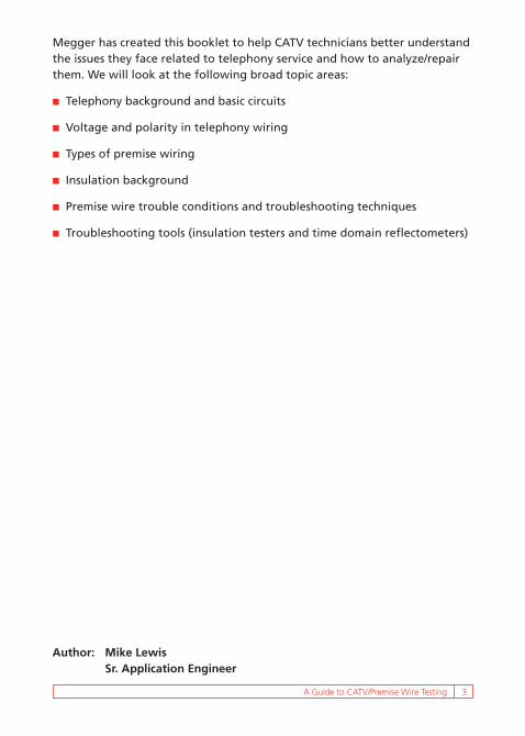
2. Connect a test clip such as a “banjo” test device on the modem or NID (see Figure 6).
3. Set the MIT410-TC selector switch to the “V” (volt) setting.
4. Connect the leads from the meter to the tip and ring of the “banjo” connector.
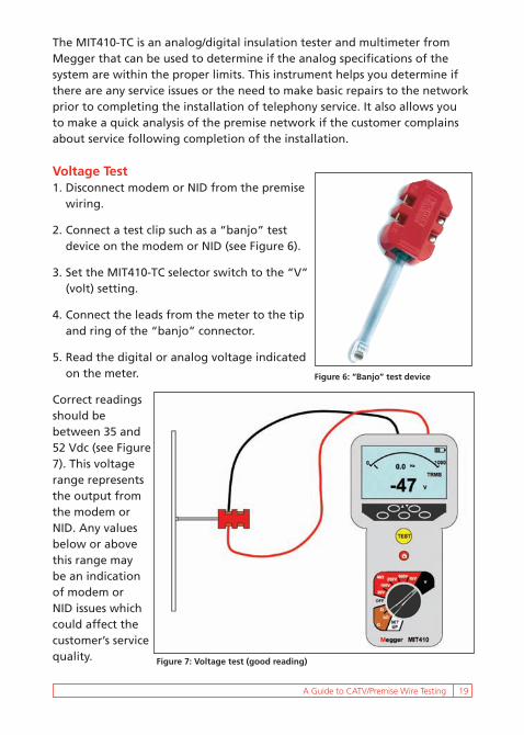
5. Read the digital or analog voltage indicated on the meter.
Correct readings should be between 35 and 52 Vdc (see Figure 7). This voltage range represents the output from the modem or NID. Any values below or above this range may be an indication of modem or NID issues which could affect the customer’s service quality.
Figure 6: “Banjo” test device
Figure 7: Voltage test (good reading)

20 A Guide to CATV/Premise Wire Testing
Ring Voltage Test1. Follow steps 1
through 4 as outlined above.
2. Using a cell phone, call the customer’s telephone number associated with the modem or NID.
3. Watch the meter (both the analog and digital readings) as the ring cycle begins. The meter will display the peak voltage rise which will then fall during the off cycle. This cycle will continue until the call is disconnected.
Correct readings should be between 50 and 90 Vac. Readings below 50 Vac (see Figure 8) indicate a problem (such as the bell not ringing).
Resistive Fault Test1. Disconnect the modem/NID from the premise wire.
2. Plug the “banjo” connector into the outlet.
3. Connect the meter test leads to the tip and ring on the “banjo” connector.
4. Set the selector switch on the MIT410-TC to the “kOhm” range.
5. Observe the analog and digital display on the meter.
Correct readings on the meter should be as follows:
n On the digital readout, > 1000 kOhms.
n On the analog scale, the pointer is positioned on the left side at the infinity mark.
Figure 8: Ring voltage test; reading indicates a problem

A Guide to CATV/Premise Wire Testing 21
This type of test result indicates that there is no apparent fault present (see Figure 9a). However, if both the analog pointer and the digital readout are moving (see Figure 9b), there is a fault present and needs to be fixed. Note that during this test, the customer’s equipment can still be plugged into the system. If a fault is indicated, you can eliminate the equipment by unplugging each set one at a time and retesting until the defective equipment is found. If there is still a fault indicated on the meter after all of the equipment has been removed, then use standard troubleshooting techniques to find and repair the fault within the premise wiring.
Figure 9a: Resistive fault test (good reading)
Figure 9b: Resistive fault test; reading indicates a fault

22 A Guide to CATV/Premise Wire Testing
Insulation Resistance TestIf the test for resistive faults (kOhms test) indicates good readings, then conduct the insulation resistance test (see Figure 10a), which involves the following procedures:
1. Disconnect the modem/NID from the premise wiring.
2. Disconnect the customer’s equipment including the telephone sets, answering machines, faxes, burglar alarm circuits, etc.
3. Plug in the “banjo” connector to the outlet where the Modem/NID was connected.
4. Set the selector switch on the MIT410-TC to the 500 volt setting.
5. Connect the meter test leads to the tip and ring on the “banjo” connector.
6. Press and hold the test button on the MIT410-TC until you can see a reading on the analog and digital scale of the meter, usually about 10 or 15 seconds.
There should be a steady progression of the pointer across the scale on the analog meter from right to left. A digital readout above 100 megohms is a good test, indicating that there are no faults within the premise wiring. Any hesitation of the pointer during the test process could indicate service issues even if the digital readout is above 100 megohms. This condition indicates that a fault exists and the meter is having trouble breaking through the fault. It is indicative of repeat trouble conditions that come and go, thus
Figure 10a: Insulation resistance test (good reading)

A Guide to CATV/Premise Wire Testing 23
resulting in repeat truck “rolls”. You should attempt to locate this type of fault so as to reduce or eliminate repeated trips. Any reading below 90 megohms indicates that the wiring is bad (see Figure 10b).
SummaryBy following the above procedures for testing voltage, resistive faults and insulation quality, you can ensure that the job is done correctly the first time, eliminating costly repeat visits and providing quality customer service.
FAULT LOCATINGOnce a problem has been identified, you must determine its location before fixing. As noted earlier, one approach is to use the “divide and conquer” method. Alternatively, a time domain reflectometer (TDR) can be used in many situations. There are two types of TDRs: full trace models that show a representation of the cable and all anomalies on the cable and digital models that give distance readouts to the first anomaly on the cable. In this section, we look at the basics of TDR technology.
TDR Technology OverviewTDRs use simple transmission line theory and pulse reflection principals to detect impedance changes along a cable. The TDR transmits high frequency electrical pulses. When applied to a cable, these pulses travel along the cable until a change in characteristic impedance is encountered. Depending on the nature of the impedance change, either all or part of the transmitted pulse will reflect back to the TDR (see Figure 11).
Figure 10b: Insulation resistance test; reading indicates a fault

24 A Guide to CATV/Premise Wire Testing
Impedance is the total resistance, inductive reactance and capacitive reactance encountered in a cable (see Figure 12). A change in a cable’s characteristic impedance will cause one of two types of reflections: positive or negative. Positive reflections are caused by increases in impedance. Increased impedance results from increases in metallic resistance or inductive reactance. Negative reflections are caused by decreases in impedance. Decreased impedance results from decreases in insulation resistance or changes in capacitive reactance.
Reading a TDR is similar to reading a map. Before reading a map you must learn what the symbols mean and before reading a TDR you must also learn what the TDR signatures represent. Refer to Figure 13 for examples of some of the direct types of signatures (traces) that might appear on a TDR screen.
When measuring distances to an event on a TDR, the TDR measures the time it takes a pulse to travel down a cable, encounter an impedance change and reflect back. By knowing the velocity of the pulse, the TDR converts this time to distance. Pulses travel at different velocities on different cables much like
Figure 12: Characteristic impedance model
Figure 11: TDR basic operation
T r a n s m i t t e r
R e c e i v e r
C o u p l e r
D i s p l a y
T D R
C a b l e P a i r

A Guide to CATV/Premise Wire Testing 25
a ball travels at different velocities through different liquids. The type of insulation and cross section geometry of a cable will affect the velocity of a pulse. The table on the follow page shows the velocity factors for common CATV cables. Velocity factors relate to the percentage of the speed of light that the pulse travels along the cable.
Figure 13: Typical TDR signatures
Openor
Load Coil
Short Circuitor
Ground Fault
Splice
GOOD WET HI-RESISTANCE
Bridge TapFollowed byEnd-of-Tap
SplitFollowed by
Re-split
Cross
Wet Section/Water Ingress
Cable Velocity Factor
BELDEN RG-59 FOAM 0.78SOLID 0.66
CAPSCAN RG-59 0.82CC 0.88
COMM/SCOPE RG-6, 11 & 59 0.82PARA I 0.82PARA III 0.87QR 0.88
CZ LABS RG-59 0.82GENERAL CABLE RG-59 0.82
MC2 0.93SCIENTIFIC ATLANTA RG-59 0.81
TRUNK 0.87TIMES FIBER RG-59 0.83
T 4, 6 & 10 0.87TR+ 0.87TX, TX10 0.89DYNAFOAM 0.9
TRILOGY (MC2) 0.93TRUNK/FEEDER (FOAM) 0.83DROP FOAM (59, 6 & 11) 0.827 SERIES 0.88MC2 0.93
Test Equipment Depot - 800.517.8431 - 99 Washington Street Melrose, MA 02176 FAX 781.665.0780 - TestEquipmentDepot.com

26 A Guide to CATV/Premise Wire Testing
If the velocity factor of a cable is unknown, it can easily be determined by connecting onto a sample cable of known length. Place the TDR’s cursor at the reflection representing the end of the cable. Simply adjust the velocity setting until the unit reports the correct length. This setting will be the velocity of propagation for the cable. If neither the velocity nor length of the cable is known, an accurate fault location can still be determined by measuring the distance to the fault from both ends of the cable. If an error exists in the velocity setting, the TDR will either over measure or under measure from both ends of the cable. The fault will be between the two measurements.
TDRs have varying pulse width settings. The larger the pulse width, the more energy; therefore, the further the signal will travel on a given cable. A TDR’s distance range is determined by how far the transmitted pulse will travel while still returning a detectable reflection. The following must be considered:
n The width of the transmitted pulse will affect the TDR’s ability to identify reflections.
n The width of the pulse is sometimes referred to as the dead zone.
n As the pulse increases in width it becomes more difficult to identify reflections. Closely spaced reflections may become masked by the dead zone.
TDR SummaryTDRs provide a method of locating the distance to an anomaly (impedance change) on a cable. Each type of impedance change has a different “signature”, or trace, that indicates the nature of the anomaly. By moving the instrument’s cursor to the beginning of the signature, you can determine the approximate distance to the problem. The TDR requires that you enter the proper velocity factor for the chosen cable to get an accurate reading, and chose the best pulse width for the application to ensure that you see the anomaly. Understanding the basics of TDR technology can save you significant time and aggravation at the job site.

A Guide to CATV/Premise Wire Testing 27
CONCLUSIONLegislation and technology have opened the once closed telephony market to the CATV industry. Offering telephony service as part of the CATV package is a great opportunity for CATV companies, but it comes with some significant service challenges. Most federal and state agencies require 99.999% reliability, and the CATV industry is struggling with the twisted pair wiring inside the customer’s premise. As more customers switch over to CATV telephony service, premise wiring issues are increasing.
When service is switched, the CATV technician often lacks the experience and equipment necessary to properly analyze the condition of the premise wiring before the transfer of service takes place. As a result, pre-existing service problems are transferred to the CATV company. Repeated customer complaints and the associated visits cost the company money, time and customer good will.
There are four basic tests that should be made at the time of switchover and when service problems arise.
Line Voltage (dc) Test: Use a volt-ohmmeter (VOM).
Ring Voltage (ac) Test: Use a VOM with the proper ac voltage ranges.
Loop Resistance Test: Use an ohmmeter.
Insulation Resistance Test: Use a megohmmeter (insulation resistance tester) with an analog arc display (pointer movement is critical) and a 500 volt measurement range.
By following the procedures for testing voltage, resistive faults, and insulation quality as outlined in this booklet, you can ensure that the job is done correctly the first time.

28 A Guide to CATV/Premise Wire Testing
PRODUCTS AVAILABLE FROM MEGGER
Megger Ground Resistance Testers
DET3 Contractor Series The DET3 Series of digital ground testing instruments from Megger is comprised of two models: an instrument for grounding and bonding tests and a unit that adds a current measuring function. With this added function, current on the ground rod can be measured for improved personnel safety and noise detection. The DET3TC includes the ART (Attached Rod Technique) method of testing which greatly reduces testing time.
Megger 1-kV Insulation Resistance Test Equipment
MIT400 SeriesThe MIT410-TC and MIT430-TC are designed specifically for use within the telecommunications industry. Unique features include a soft canvas carrying bag with shoulder strap and snap hook to attach to a tool belt, and a “bed of nails” test lead set.
The model MIT430-TC offers extensive results storage capability for later recall and Bluetooth download capability for wireless transfer of stored results to a PC.
The MIT410-TC and MIT430-TC allow the user to determine the condition of the insulation of the twisted copper cable pairs, which could cause problems for services such as voice, video, and data or VOIP. When the insulation becomes weak or brittle, causing cracks or exposing copper within the cable, or water ingresses into the cable, the insulation resistance test will identify these situations immediately.

A Guide to CATV/Premise Wire Testing 29
The DET3 Series digital ground testers are powered by eight AA batteries which give excellent testing time — the status of the batteries is given by a bar graph on the LCD. The instruments are designed to meet stringent safety standards and are rated CAT IV 100V.
Each DET3 comes complete with test leads, stakes, batteries, calibration certificate and rugged polypropylene carry case.
DET4T2 Enhanced Series The newest ground testers from Megger offer a comprehensive solution to ground resistance and soil resistivity testing needs. The instruments provide such functions as 2 pole, 3 pole, 4 pole, Attached Rod Technique (ART), stakeless, leakage current and ground noise voltage measurements. All models include selectable output voltage (25 V or 50 V). The DET4TC2 and DET4TCR2 offer four selectable test frequencies (94, 105, 111 and 128 Hz) for improved testing in noisy environments.
An optional ICLAMP augments the traditional fall-of-potential measurement method with ART which allows electrode testing without disconnection and also leakage current measurement down to 1 mA. The VCLAMP, a second optional clamp, enables true stakeless measurements to be made where driving a stake is not practical.
The DET4TC2 and DET4TD2 are powered by eight AA batteries which give excellent testing time. The DET4TR2 and DET4TCR2 are powered from rechargeable AA cells. For added convenience on all four units, the battery status is displayed using a bar graph.
The Megger DET4T2 Series is designed to meet stringent safety standards and is rated CAT IV 100V.

30 A Guide to CATV/Premise Wire Testing
Megger DET10C and 20C Clamp-on ModelsThe Megger models DET10C and 20C are a useful addition to the more traditional methods of earth/ground resistance testing that may require disconnection and the use of stakes or ground rods. Simply clamp around the conductor or stake/rod and measure the resistance to ground quickly and accurately.
The DET10C and 20C can be used to measure earth/ground resistance in multiple loop installations without disconnecting the earth or ground, allowing quick and easy testing in total safety. These clamp-on testers feature improved ground resistance ranges from 0.025Ω to 1550Ω and ground leakage current from 0.2 mA to 35 A.
The units are rugged, compact and have configurable audible alarms. They feature auto shutdown (which is also configurable), data storage and self calibration on power-up, and are supplied with a calibration loop – all contained in a rugged carry case.
The DET20C also comes with an USB interface cable and is compatible with Megger Download Manager Software (included) allowing further analysis and storage of data.

A Guide to CATV/Premise Wire Testing 31
Megger Time Domain ReflectometersWhether locating cable faults or testing the integrity of communication, power, or control cables, TDRs available from Megger provide fast and accurate results. Models with built-in or optional blocking filters can be used on energized cable up to a specified voltage limitation. Models without blocking filters are for de-energized cable only.
Megger TDR900n Ideal for testing low-voltage cable
n Digital read-out TDR and cable length meter
n Autoranging for measuring power, telephony, CATV and LAN cable lengths
n Extra large, high resolution backlit LCD
n Internal library of 39 standard cable types
n Cable length calibration function
n Used only on de-energized circuits
Megger TDR500n Cost effective, graphical TDR
n Full TDR trace at a low cost
n Adjustable velocity factor
n Warble tone generator for tracing faulty cable pairs
n Used only on de-energized circuits

32 A Guide to CATV/Premise Wire Testing
Megger CFL535Fn Identifies and locates faults on metallic cables
n No blocking filter required for live line testing up to 300 V ac
n Output pulse amplitude control
n Automatic event finder key
n Graphical help menu
n Dual channel, stress and comparison of previous traces
n Comes equipped with dual fused, fitted test leads
Megger CFL510Fn Tests virtually all types of cable
n Automatic event finder key
n No blocking filter required for live line testing up to 300 V ac
n Simple keypad; bright, backlit LCD

Megger is your source for cable TV premise wiring testing needsMegger offers the following high-quality instruments for testing
telecommunication systems.
n Insulation Resistance Test Equipment n Battery Test Equipment
n Ground Resistance Test Equipment n Time Domain Reflectometers
n Multimeters/Clampmeter n Low Resistance Ohmmeters
The word “Megger” is a registered trademark.
Test Equipment Depot - 800.517.8431 - 99 Washington Street Melrose, MA 02176 FAX 781.665.0780 - TestEquipmentDepot.com