guidance methods for accurate in–flight alignment of navy ... · mark jones thomas r. pepitone...
TRANSCRIPT

Guidance Methods for Accurate In–FlightAlignment of Navy Theatre Wide Missiles
15 May 2001
Ernest J. OhlmeyerCraig PhillipsDavid HangerMark Jones
Thomas R. Pepitone
NDIA Missiles &Rockets Symposium and Exhibition
Report Documentation Page
Report Date 15052001
Report Type N/A
Dates Covered (from... to) -
Title and Subtitle Guidance Methods for Accurate InFlight Alignment ofNavy Theatre Wide Missiles
Contract Number
Grant Number
Program Element Number
Author(s) Ohlmeyer, Ernest J.; Phillips, Craig; Hanger, David;Jones, Mark; Pepitone, Thomas R.
Project Number
Task Number
Work Unit Number
Performing Organization Name(s) and Address(es) NAVSEA, Dahlgren
Performing Organization Report Number
Sponsoring/Monitoring Agency Name(s) and Address(es) NDIA (National Defense Industrial Association 2111Wilson Blvd., Ste. 400 Arlington, VA 22201-3061
Sponsor/Monitor’s Acronym(s)
Sponsor/Monitor’s Report Number(s)
Distribution/Availability Statement Approved for public release, distribution unlimited
Supplementary Notes Proceedings from Armaments for the 2nd Annual Missiles & Rockets Symposium & Exhibition, 14-16May 2001 sponsored by NDIA., The original document contains color images.
Abstract
Subject Terms
Report Classification unclassified
Classification of this page unclassified
Classification of Abstract unclassified
Limitation of Abstract UU
Number of Pages 29

• Background
• ADOP - In-Flight Alignment Metric
• Second Stage Guidance Methods
• In-Flight Alignment Analysis
• Summary
OUTLINE

Background

NTW Concept of Operation
Stage 1Separation
Stage 2Separation
Stage 1• IMU initialized at launch• Radar acquisition
Stage 2• Command guidance to a specified injection velocity vector• Trajectory shaping to maximize kinematic performance
or improve IFA• GPS acquisition
Stage 3• 1 pulse or 2 pulse TSRM• Burnout reference guidance during pulses to
produce a ballistic collision course to minimize ZEM• Nosecone ejection after final pulse or between pulses
Stage 4• KW IR acquisition of target• KW divert used to steer out
3RD stage ZEM
STAGE 1 STAGE 2STAGE 4STAGE 3
Stage 3 Separation
γINJ
First Pulse
Second Pulse

Successful Intercept Requirements
FOR
LOS To Target
Pointing Requirement
INTERCEPTX
KW DIVERTCAPABILITY
Target
Target
Divert Requirement
• At kinetic warhead (KW) separation thetarget must be within the seeker field ofregard (FOR)
• The zero effort miss (ZEM) must bewithin the kinetic warhead divertcapability
KW
KW

In-flight Alignment Required to AchievePointing Error Allocations
• The missile IMU alignment with respect to the ship defined navigation (ECEF)coordinate frame may have a large unknown error at launch (up to 26 mrad)
• This error dominates the error budget and degrades performance
• The in-flight alignment (IFA) process calibrates the IMU alignment withrespect to the navigation coordinate frame during flight
• An integrated GPS/IMU missile navigation system was first used onStandard Missile to perform this in-flight alignment as part of the TerrierLEAP experiment
In order To Meet The Pointing Error Allocation TheMissile Initial Attitude Error Must Be Reduced InflightIn order To Meet The Pointing Error Allocation The
Missile Initial Attitude Error Must Be Reduced Inflight
How Does Inflight Alignment Work?
• Background Facts
– The major alignment error component to be calibrated is the IMU alignmentwith respect to the navigation frame (≤ 26 mrad)
– When accelerations are transformed with an IMU alignment error to thenavigation frame an acceleration error develops
• The Aiding Process
– Acceleration errors, when integrated, result in velocity errors which result,in turn, in position errors
– Navigation errors are observable by comparing inertial navigation estimatesof the position and velocity to measurements from outside sources:
• Radar measurements (position)
• GPS measurements (position & velocity)
– Errors are corrected via an on-board Kalman Filter
In-Flight Alignment Metric“ ADOP ”
ADOP - The Alignment Metric
• Attitude Dilution Of Precision (ADOP) was developed as a trajectoryinduced observability metric of in-flight alignment
• There are two fundamental ingredients in the ADOP metric
• The missile acceleration time profile
• The GPS and radar measurement noise error time profiles
• An interpretation of the ADOP metric
• Missile total (RSS) attitude alignment error with respect to thenavigation coordinate frame (3-σ value expressed in milli-radians)
• A value less than 5 mrad is considered good performance and a valuegreater than 5 mrad is considered degraded performance

ADOP Attributes
• Trajectory induced observabilitymetric for in-flight alignment
• A simplified error model that iseconomical to run
• Provides lower bound on attitudeerrors for benchmarking in-flightalignment performance
• Can be used to generate observabilitymaps over the tactical battlespace
• Shows difficult regions of thebattlespace for in-flight alignment
> 20 20 - 15 15 - 10 10 - 5 5 - 0ADOP Values (mrad)
Ground Range
Alti
tude
ADOP Observability Contour MapSpanning the Battlespace
Poor IFA
Better IFA

Second Stage Guidance Methods

• Cross Product Guidance (CPG)• Guides to a specified injection velocity
vector• Approximates an optimal kinematic
trajectory
• Delayed Cross Product Guidance (DCPG)• Similar to CPG, guides to a specified
injection velocity vector• Guidance initiation is delayed to
improve IFA
• Modified Cross Product Guidance (MCPG)• Similar to CPG, guides to a specified
injection velocity vector• Guidance initiation is delayed• Adds a shaping term to improve IFA
IFA Performance Examined for3 Second Stage Guidance Laws
Stage 1Separation
Stage 2Separation
γINJ
Stage 1
Stage 2
γINJ
γINJ
CPG
DCPGMCPG

Guidance Law Definitions
• Cross Product Term:
•CPG, DCPG, & MCPG
•Nulls heading error andforces convergence toinjection velocity vector
•K1 gain is scheduledwith γINJ to minimizeangle-of-attack
• Shaping Term:
•MCPG only
•Applies short-livedacceleration in directionopposite to cross productterm to induce observability
•K2 gain is scheduled withγINJ to maximize effect inregions of poor IFA
u(t)KusindVKA 21C ˆˆ +−=r
u(t)K2 ˆ+ v
vINJ^
u δ
( )
uu
u
sindu
vvvu INJ
=
=
××=
ˆ
ˆˆˆ
vectorunit velocity injection commandedvvectorunit velocitycurrent v
magnitude velocityV
vector onaccelerati commandedA
INJ
C
===
=
ˆˆ
gain term shapingKgain termproduct crossK
v and v between angledvectorunit product crossu
2
1
INJ
====
ˆˆˆ
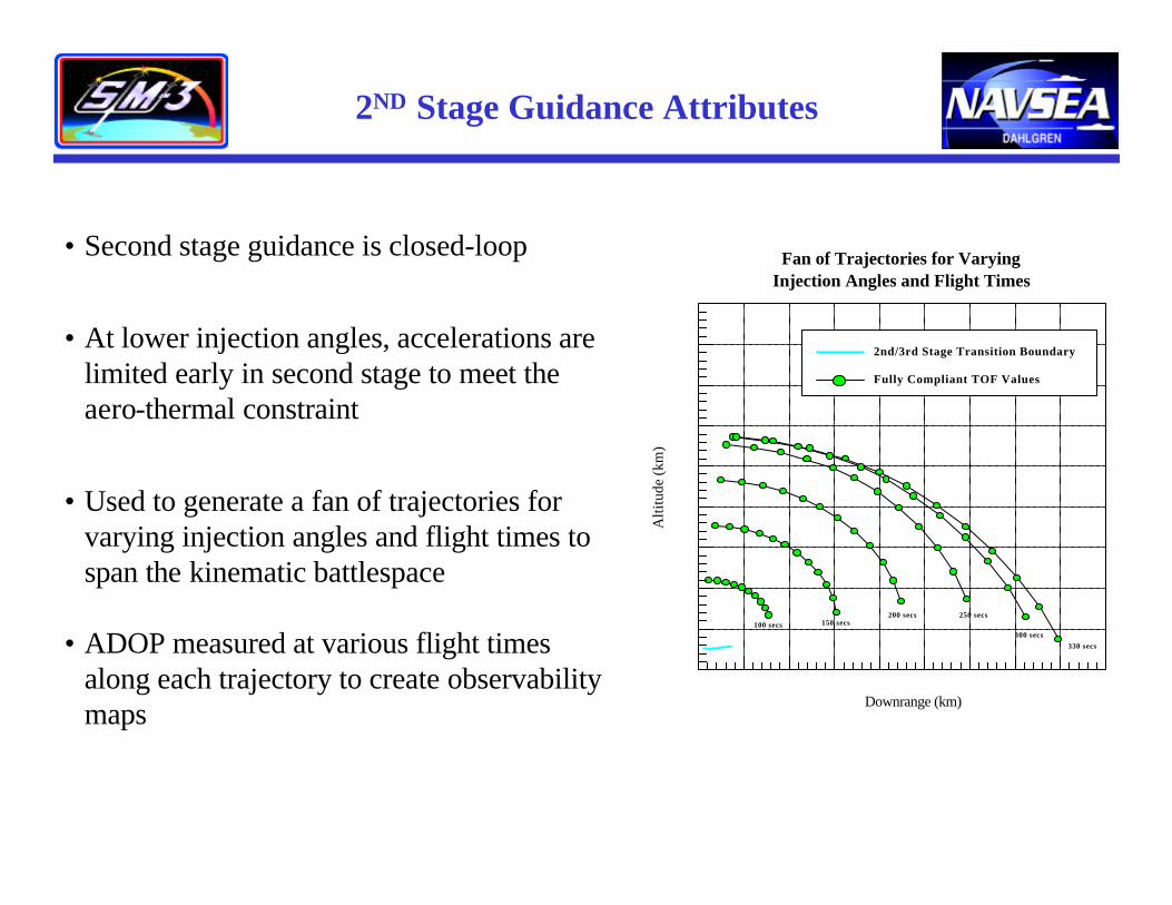
2ND Stage Guidance Attributes
• Second stage guidance is closed-loop
• At lower injection angles, accelerations arelimited early in second stage to meet theaero-thermal constraint
• Used to generate a fan of trajectories forvarying injection angles and flight times tospan the kinematic battlespace
• ADOP measured at various flight timesalong each trajectory to create observabilitymaps
100 secs 150 secs200 secs 250 secs
300 secs330 secs
Alti
tude
(km
)
Downrange (km)
Cross-Product Steering Guidance Flyout TOF Profiles
2nd/3rd Stage Transition Boundary
Fully Compliant TOF Values
Fan of Trajectories for VaryingInjection Angles and Flight Times
IFA Analysis

• IFA performance measured by ADOPobservability maps covering the battlespace
• ADOP maps generated for each guidance law:• CPG• DCPG• MCPG
• ADOP maps examined for two types of aiding:• Radar only• Radar & GPS
• ADOP maps examined at two trajectory events:• 2ND/3RD stage separation• 3RD/4TH stage separation
IFA Analysis for 3 Guidance Laws

Example ADOP Histories
• ADOP time histories show improvement in IFA performance at 3rd/4th stageseparation over 2nd/3rd stage separation
• IFA performance improvement at the later flight time results from• Additional time for aiding from outside sensors• Additional accelerations from the 3rd stage
• ADOP time histories show improvement in IFA performance at 3rd/4th stageseparation over 2nd/3rd stage separation
• IFA performance improvement at the later flight time results from• Additional time for aiding from outside sensors• Additional accelerations from the 3rd stage
ADOP Histories for Radar Only Aidingfor the 3 Guidance Methods
2nd/3rd Stage Separation
3rd/4th Stage Separation
0.0
5.0
10.0
15.0
20.0
25.0
30.0A
DO
P (m
rad)
Time (sec)
CPG
DCPG
MCPG

Alti
tude
Ground Range
Alti
tude
Ground Range
Alti
tude
Ground Range
Alti
tude
Ground Range
Rad
ar O
nly
Rad
ar &
GP
S
> 20
20 - 15
15 - 10
10 - 5
5 - 0
ADOP Values(mrad)
CPG ADOP Maps
• IFA improves from 2nd/3rd stage separation to 3rd/4th stage separation for both aiding methods• IFA improves for radar & GPS aiding over radar only aiding• IFA requirement satisfied over majority of the battlespace for the radar & GPS aiding case at
the 3rd/4th stage separation point
• IFA improves from 2nd/3rd stage separation to 3rd/4th stage separation for both aiding methods• IFA improves for radar & GPS aiding over radar only aiding• IFA requirement satisfied over majority of the battlespace for the radar & GPS aiding case at
the 3rd/4th stage separation point
2nd/3rd stage separation 3rd /4th stage separation

DCPG ADOP Maps
Ground Range
Alti
tude
Ground Range
Alti
tude
Rad
ar O
nly
Rad
ar &
GP
S
> 20
20 - 15
15 - 10
10 - 5
5 - 0
ADOP Values(mrad)
• IFA improves from 2nd/3rd stage separation to 3rd/4th stage separation for both aiding methods• IFA improves for radar & GPS aiding over radar only aiding• IFA requirement satisfied over majority of the battlespace for the radar & GPS aiding case at
the 3rd/4th stage separation point
• IFA improves from 2nd/3rd stage separation to 3rd/4th stage separation for both aiding methods• IFA improves for radar & GPS aiding over radar only aiding• IFA requirement satisfied over majority of the battlespace for the radar & GPS aiding case at
the 3rd/4th stage separation point
2nd/3rd stage separation 3rd /4th stage separation
Ground Range
Alti
tude
Ground Range
Alti
tude

Ground Range
Alti
tude
Ground Range
Alti
tude
MCPG ADOP Maps
Rad
ar O
nly
Rad
ar &
GP
S
> 20
20 - 15
15 - 10
10 - 5
5 - 0
ADOP Values(mrad)
• IFA improves from 2nd/3rd stage separation to 3rd/4th stage separation for both aiding methods• IFA improves for radar & GPS aiding over radar only aiding• For radar & GPS aiding, IFA requirement satisfied over most of the battlespace at 2nd/3rd
stage separation and satisfied over the entire battlespace at 3rd/4th stage separation
2nd/3rd stage separation 3rd /4th stage separation
Ground Range
Alti
tude
Ground Range
Alti
tude

Ground Range
Alti
tude
Ground Range
Alti
tude
Alti
tude
Ground Range
0.5 - 0.6 0.6 - 0.7 0.7 - 0.8 0.8 - 0.9 0.9 - 1.0
Normalized Velocities
DCPG and MCPG Kinematic Penalties
CPG DCPG MCPG
Maps of Burnout Velocity
• Battlespace is slightly reduced in ground range with DCPG and further reduced inaltitude with MCPG
• Burnout velocities are slightly decreased for DCPG and further reduced for MCPGin the regions of largest trajectory shaping
• Battlespace is slightly reduced in ground range with DCPG and further reduced inaltitude with MCPG
• Burnout velocities are slightly decreased for DCPG and further reduced for MCPGin the regions of largest trajectory shaping

Summary

Summary
• IFA is necessary to meet the KW seeker pointing requirement
• ADOP is the trajectory induced IFA observability metric
• IFA performance has been analyzed for three different second stageguidance laws
• The addition of GPS aiding significantly improves IFA
• The longer aiding period for 3rd/4th stage separation improves IFA over2nd/3rd stage separation
• Both DCPG and MCPG provide improved IFA performance over CPG
• Using MCPG and with radar & GPS aiding, the IFA requirement issatisfied over the majority of the battlespace at 2nd/3rd stage separationand over the entire battlespace at 3rd/4th stage separation
• Both burnout velocity and the overall battlespace are slightly reducedfor DCPG and MCPG

Backup Slides

Example Pointing Error Allocation
KW Field of Regard Radius11.0 mr [15.6 mr]
Boresight Error Requirement9.6 mr 3σ [13.6 mr]
KW Attitude Error4.2 mr
KW ACSControl1.5 mr
KW Seekerto KW IMU
2.5 mr
KW IMU to 3rd IMUTransfer Alignment
3 mr
Msl Stage 3 IMU toTrue SBEF (ECEF)
5.0 mr (A32)
Third Stage Attitude7.1 mr
Ship Radarto Missile Stage 3 IMU
Inflight Alignment7.1 mr (A21)
Uncorrelated Relative Target/MissileState Errors From Ship
5.0 mr [10.8 mr]
Filter Position Errors450 m, 4.6 mr
Filter Velocity Errors5 m/s x 5 s = 25 m, 0.26 mr
Time Tag Errors(small)
Target-to-Missile Track Bias131m, 1.3 mr [950 m, 9.7 mr]
add
Notes:- Bold numbers are allocated values- Shaded boxes indicate where GPS measurements are used to achieve allocations- Brackets are target/missile track on different radar faces
GPS used to achieve allocation
0.5 mr x 261300 m = 131 m [3.6 mr]
20 ms
Assumptions:- Pr target within radius = 0.9974- VC = 4068 m/s- TGO = 24 s- RSHIP/TARGET = 261.3 km- Angle Error = Range Error / (VCx TGO)
Range Error = Alignment x VC x TGO
X 3.45 / 3
GPS used to achieve allocation
RSS
RSS
RSS

ρ1 ρ2ρ3
ρ4
L1
L2
PM/S
EARTHCENTER
SBEFREFERENCE
OWNSHIPREFERENCE
{ρi , i = 1,2,3,4} = GPS Pseudo Range Measurements {∆ρi , i = 1,2,3,4} = GPS Delta Pseudo Range Measurements
PM/S = Position Of The Missile Relative To The Ship From AEGIS WCS Radar Track Processing
L2 = Linear Position Change From The Initial SBEF Reference
L1 = Ship Based Earth Fixed Reference Vector
Note:L1 and L2 are taken fromthe AEGIS Ship NavigationSystem
AEGIS Derived Missile Position In The ECEF Frame RequiresBoth Radar Measurements And Ship Navigation System Data
AEGIS Derived Missile Position In The ECEF Frame RequiresBoth Radar Measurements And Ship Navigation System Data
GPS And Radar Measurement Aiding ForMissile Navigation
PM

• 3 Position Errors
• 3 Velocity Errors
• 3 Missile Attitude Errors
• 3 Gyro Drifts
• 3 Accelerometer Biases
• 2 GPS Receiver Clock Errors (Bias & Drift)
• 3 SPY Radar Face Misalignments
• 3 Ship Initial Position Biases
GAINS Kalman Filter States

Error Budget for ADOP Analyses
Note: The radar track of the missile is assumed to be constrained to SPY face 0.
1σ ValueNavigation System ErrorX Y Z
Initial Position Error (m) 115.5 115.5 115.5Initial Velocity Error (m/sec) 5 5 5Initial Attitude Error (mrad) 8.72 8.72 8.72Radar Face Misalignment (mrad) 0.8 0.8 0.8Ship Initial Position Error (m) 1852 1852 100Position Process Noise (m/rt-sec) 0.1 0.1 0.1Accelerometer Random Walk (µg/rt-hz) 85 85 85Gyro Random Walk (deg/rt-hr) 0.125 0.125 0.125Radar Face Noise (µrad/rt-sec) 0.1 0.1 0.1Ship Position Drift (m/rt-hr) 61.1 61.1 61.1Radar Position Measurement Error (m) ƒ (range) ƒ (range) ƒ (range)GPS Position Measurement Error (m) 10 10 10GPS Velocity Measurement Error (m/sec) 0.3 0.3 0.3
Ship Motion Parameters Nominal Value
Ship Speed (kts) 7Roll Sinusoidal Amplitude (deg) 15Pitch sinusoidal Amplitude (deg) 5Yaw Sinusoidal Amplitude (deg) 3Roll Sinusoidal Period (sec) 15Pitch Sinusoidal Period (sec) 7Yaw Sinusoidal Period (sec) 21

ADOP Calibrated Against DetailedNavigation Simulation
• ADOP Alignment Error Comparisons with Detailed6-DOF Navigation Simulation:
A32 Alignment Error @ KW Ejection(mrad)
Radar Only Radar & GPSTacticalCase ADOP NAVSIM ADOP NAVSIM
2 12.9 15.7 2.7 4.2
3 21.4 22.5 3.2 3.8
6 19.2 21.8 3.7 5.8
11 16.3 18.2 3.0 4.2
TrajectoryCase
ADOP