guidance manual for iron and steel manufacturing ... manual for iron and steel manufacturing...
TRANSCRIPT

Guidance Manual for
Iron and Steel Manufacturing Pretreatment Standards

GUIDANCE MANUAL FOR
IRON AND STEEL MANUFACTURING PRETREATMENT STANDARDS
Prepared by The
Industrial Technology Division Office of Water Regulations and Standards
and Permits Division
Office of Water Enforcement and Permits
September 1985
U.S. Environmental Protection Agency 401 M Street, S.W.
Washington, DC 20460

UNITED STATES ENVIRONMENTAL PROTECTION AGENCY WASHINGTON. D.C. 20460
OFFICE OF WATER
MEMORANDUM
SUBJECT: Guidance Manual for Iron and Steel Manufacturing Pretreatment Standards
FROM: Martha G. Prothro, Director Permits Division on (EN-336)
Jeffery D. Denit, Director Industrial Technology Division
TO: Users of the Guidance Manual
This manual provides information to assist Control Authorities and Approval Authorities in implementing the National Categorical Pretreatment Standards for the Iron ad Steel Manufacturing Point Source Category (40 CFR Part 420). It is designed to supplement the more detailed documents listed as reference in the manual; it Fe not designed to replace then. If you need more complete information on a specific item, you should refer to the appropriate reference.
EPA developed this manual to fill several needs. First, it should be useful to Control Authorities in responding to most routine inquiries from regulated mills. More complex inquiries may require the use of the listed references.
Second, the manual addresses application of the combined wastestream formula to Integrated facilities with regulated and unregulated wastestreams. It also provides current information on removal credits, variances and reporting requirements. It further incorporates the final amendment to the categorical standards reflecting the settlement of litigation issues for the final rule.
The manual is the third, in a series of industry-specific guidance manuals for implementing categorical pretreatment standards, and several others will be Issued soon. We also plan to issue manuals covering removal credits, the combined wastestream formula and the conversion of production-based categorical standards to equivalent mass-based standards.
Please feel free to write to either the Office of Water Regulations and Standards (WH-552) or the Office of Water Enforcement and Permits (EN-336) with suggestions, additions or improvements.

ACKNOWLEDGEMENTS
We wish to acknowledge the considerable efforts and cooperation of the many people whose contributions helped in the successful completion of this document.
The document was prepared under the direction of Mr. Marvin Rubin, Chief, Analysis and Support Branch, Industrial Technology Division and Dr. James Gallup, Chief, Municipal Programs Branch, Off ice of Water Enforcement and Permits. Mr. Gary Amendola of EPA Region V, ad Hr. Ed Dulaney of the Industrial Technology Division are to be acknowledged for their valuable input. In addition, members of the Office of General Counsel and other members of the Industrial Technology Division and Office of Water Enforcement and Permits are acknowledged for their Important contributions.
This document was prepared by JRB Associates under EPA Contract No. 68-01-6514.

TABLE OF CONTENTS
Chapter page
1. INTRODUCTION . . . . . . . . . . . . . . . . . . . . . . . . . . . . . . . . . . . . . . . . . . . . . . . . . . . l-l
1.1 HISTORY OF THE IRON AND STEEL MANUFACTURING CATEGORICAL PRETREATMENT STANDARDS . . . . . . . . . . . ..I...................... 1.2
2. IRON AND STEEL CATEGORICAL PRETREATMENT STANDARDS (40 CFR PART 420) . . . . . . . . . . . . . . . . ..................................... 2.1
2.1 AFFECTED INDUSTRY ......................................... 2-1 2.2 PRETREATMENT STANDARDS FOR THE IRON AND STEEL MANUFAC-
TURING CATEGORY ........................................... 2-1 2.3 RELATIONSHIP TO ELETROPLATING AND METAL FINISHING ......... 2-21 2.4 POLLUTANTS EXCLUDED FROM REGULATION ....................... 2-21 2.5 COMPLIANCE DATES .......................................... 2-21
3. TREATMENT TECHNOLOGIES ......................................... 3-1 . 3.1 TREATMENT OF COKEMAKING WASTES ............................ 3-1 3.2 TREATMENT OF SINTERING WASTE ............................. 3-2 3.3 TREATMENT OF IRONMAKING WASTES ............................ 3-2 3.4 TREATMENT OF STEELMAKING WASTES ........................... 3-3 3.5 TREATMENT OF VACUUM DEGASSING WASTES ...................... 3-4 3.6 TREATMENT OF CONTINUOUS CASTING WASTES .................... 3-4 3.7 TREATMENT OF HOT FORMING WASTES ........................... 3.5 3.8 TREATMENT OF SALT BATH DESCALING WASTES ................... 3.6 3.9 TREATMENT OF ACID PICKLING WASTES ......................... 3.7 3.10 TREATMENT OF COLD ROLLING WASTES .......................... 3.7 3.11 TREATMENT OF ALKALINE CLEANING WASTES ..................... 3.8 3.12 TREATMENT OF HOT COATING WASTES ........................... 3.8
4. REQUIREMENTS OF THE GENERAL PRETREATMENT REGULATIONS.......... 4.1
4.1 INTRODUCTION .............................................. 4-1 4.2 CATEGORY DETERMINATION ............................ 4-2 4.3 MONITORING AND REPORTING REQUIREMENTS OF THE GENERAL
PRETREATMENT REGULATIONS .................................. 4-2
4.3.1 Baseline Monitoring Reports ........................ 4-2 4.3.2 Report on Compliance ............................... 4-4 4.3.3 Periodic Reports and Continued Compliance .......... 4-4 4.3.4 Notice of Slug Loading ............................. 4-5 4.3.5 Monitoring and Analysis to Demonstrate
Continued Compliance ............................. 4-5 4.3.6 Signatory Requirements for Industrial Users
Reports .......................................... 4-5 4.3.7 Recordkeeping Requirements ......................... 4-5
i

TABLE OF CONTENTS (Continued)
Chapter Page
4.4 APPLICATIONS OF THE COMBINED WASTESTREAM FORMULA 4-6
4.4.1 CWF Conditions .................................. 4.4.2 Monitoring Requirements for Industrial Users
Using the CWF ................................... 4.4.3 Application of the CWF ..........................
4.5 REMOVAL CREDITS ........................................ 4-11 4.6 FUNDAMENTALLY DIFFERENT FACTORS VARIANCE ............... 4-12 4.7 LOCAL LIMITS ........................................... 4-12
REFERENCES . . . . . . . . . . .......................................
4-7
4-7 4-7
R-1
ii
LIST OF TABLES
Table Page
2.1 PRETREATMENT STANDARDS FOR EXISTING SOURCES (PSES) ............. 2-9
2.2 PRETREATMENT STANDARDS FOR NEW SOURCES (PSNS) .................. 2-15
2.3 POLLUTANTS EXCLUDED FROM IRON AND STEEL REGULATION ............. 2-22
4.1 COMBINED WASTESTREAM FORMULA ................................... 4-8
4.2 COMBINED WASTESTREAM FORMULA EXAMPLE CALCULATION ............... 4-9
iii

1. INTRODUCTION
The National Pretreatment Program established an overall strategy
for controlling the introduction of nondomestic wastes to publicly owned treatment works (POTWs) in accordance with the overall objectives of the Clean Water Act. Sections 307(b) and (c) of the Act authorize the Environmental Protection Agency to develop national pretreatment standards for new and existing dischargers to POTWs. The Act made these pretreatment standards enforceable against dischargers to publicly owned treatment works.
The General Pretreatment Regulations (40 CFR Part 403) establish administrative mechanisms requiring nearly 1,500 POTWs to develop local pretreatment programs to enforce the general prohibitions, specific prohibitions and Categorical Pretreatment Standards. These Categorical Pretreatment Standards are designed to prevent the discharge of pollutants that pass through, interfere with, or are otherwise incompatible with the operation of the POTWs. The standards are technology-based for removal of toxic pollutants and contain specific numerical limits based on an evaluation of specific technologies for the particular industry, categories. As a result of a settlement agreement between EPA and the Natural Resources Defense Council (NRDC), EPA was required to develop Categorical Pretreatment Standards for 34 industrial categories with a primary emphasis on 65 classes of toxic pollutants.
This manual will provide guidance to POTWs on the implementation and enforcement of the Categorical Pretreatment Standards for the Iron and Steel Manufacturing Category. This document is based primarily on two sources: Federal Register notices, which include the official announcements of the Categorical Standards, and the Final Development Document for Iron and Steel Manufacturing, which provide a summary of the technical support for the regulations. Additional information on the regulations, manufacturing processes, and control technologies can be found in these sources. A listing of the references used in the development of this manual is provided at the end of this document.
1-1

1.1 HISTORY OF THE IRON AND STEEL MANUFACTURING CATEGORICAL PRETREATMENT STANDARDS
Steel manufacturing involves many processes, which require large quanti-
ties of raw materials. Because of the variety of products and processes in
this industry, operations vary from plant to plant. Steel facilities range
from plants engaging in a few production processes to extremely large inte-
grated complexes engaging in several or all processes. Even the smallest
steel facility represents a large industrial complex.
The steel industry can be segregated into two major components, raw
steelmaking, and forming and finishing operations. In the first, coal is
converted to coke, which is then combined with iron ore and limestone in a
blast furnace to product iron. The iron is purified into steel in tither open
hearth, basic oxygen or electric arc furnaces. Finally, the steel can be
further refined by vacuum degassing. The second component, following the
steelmaking processes, includes hot forming (including continuous carting) and
cold finishing operations. Primary hot forming mills reduce steel ingots to
slabs or blooms and secondary hot forming mills reduce them to billets,
plates, shapes, strips, and other products. Steel finishing operations
involve other processes that do little to alter the dimensions of the hot
rolled product, but impart desirable surface or mechanical properties.
Water is essential to the industry and is used in appreciable quantities
in virtually all operations. An average of 40,000 gallons of water is used in
producing every ton of finished steel, making this one of the highest water
users of any manufacturing industry. During the raw steelmaking and forming
and finishing operations, toxic, nonconventional and conventional pollutants
enter the wastewaters. EPA’s survey of iron and steel mills identified 141
pollutants in plant effluents. Some of these pollutants pass through POTW
treatment systems, interfere with biological treatment, or contaminate POTW
sludges. Pretreatment alternatives for the iron and steel industry art
designed to control toxic metal pollutants and to recycle wastewater to the
manufacturing process. Common treatment technologies include oil skimming,
metals precipitation, sedimentation, steam stripping, solvent extraction,
biological oxidation (coke wastes), thickening, filtration, and vacuum filter
1-2
dewatering. Typically, the design, purchase and installation of this
eguipnent requires 18 to 36 months.
Pretreatment standards for the iron and steel industry regulation were first proposed in February 1974, and wer8 first pmmlgated on June 28,
1974. the most recent final regulations, which established specific nunberical limitations falling within 10 of the 12 subcategories, were propos& in January 1981 and finalized on May 27, 1982.
Petitions to review the final iron and steel industry regulation wr8
later filed by certain mmbers of the iron arxl steel industry arri the Natural Ftesources Defense Camcil Inc. (NRDC). The challenges raised wer8 consolidated into one lawsuit, at-d in February 1983, the petitiorrers and EPA reached a settltment agreemnt. This axqmzhensive settlenrent resolved issu8s related to th8 steel inckmtty stamkds and on Octcber
14, 1983, changes to the regulation ore proposed. These major amm&mnts to the Ircm and Steel Standards ore prumlgated on May 17, 1984 (49 FR 21024) and include:
(1) An interim regulation establishing the method for calculating applicable mass-based pretreatmmt standards;
(2) Establishment of July 10, 1985 as date of final mliance with iron and steel pretreabnent star&&s;
(3 1 Pretreatment ma1 credits for phenols measured by the 4 AAP KU3thOd;
(4 1 Starrdards that are slightly hfgher for lead ard zinc in the Sintering and Irommking Subcategories:
(51 Standards that ar8 slightly higher for lead ad zinc in th8 Acid Pickling Subcategory:
(6) Modified effluent limitations and standards for zinc in th8 Hot coatirq Subcategoty;
(7) Modified canbined wastestrean fomla to alI- control authorities t0 8~8rCi88 jtXkpU3nt t0 d8t8mine whether bloxlmm and fMmcoMaCt cmlirq strems are dilution or unregulated process stmaae;
(81 Regulation for pemittirg nminal discharg8S of spent oil or water solution in the cold worked pipe and tube segnenta of the Cold Pollitx~ Subcategory, with a statenent that limits ard standards for process wastewaters not regulated by prior regdation are to be developed on a CaSeby-CaSe basis.
l-3

2. IRON AND STEEL CATEGORICAL PRETREATMENT STANDARDS (40 CFR PART 420)
2.1 AFFECTED INDUSTRY
The Iron and Steel Standards are applicable to wastewater discharged from
industries included within the Standard Industrial Classification (SIC) Major
Group 33 - Primary Metal Industries. Those parts of the industry covered by
this regulation are the subgroup SIC numbers 3312 (except Coil Coating), 3315,
3316 and 3317 and parts of 3479.
In developing this regulation, EPA determined that different effluent
limitations art appropriate for distinct segments of the Industry. The Agency
identified 12 main process subcategories which art:
1. Cokemaking 7. Hot Forming 2. Sintering 8. Salt Bath Descaling 3. Ironmaking 9. Acid Pickling 4. Steelmaking 10. Cold Forming 5. Vacuum Degassing 11. Alkaline Cleaning 6. Continuous Casting 12. Hot Coating
These twelve Iron and Steel Operations art briefly diecussed below:
1. Cokemaking
Coke plants art operated at Integrated facilities to supply coke for producing iron in blast furnaces or at stand-alone facilities to supply coke to other users. Nearly all active coke plants also product usable byproducts such as coke oven gas, coal tar, crude or refined light oils, ammonium sulfate or anhydrous ammonia, and naphthalene. A byproduct coke plant consists of ovens in which bituminous coal is heated without air to drive off volatile compo- nents. The coke is supplied to blast furnaces, while the volatile components are recovered and processed into byproduct materials.
The most significant wastewaters generated during byproduct coke- making and byproduct recovery operations art excess ammonia liquor, final cooler wastewater, light oil recovery wastewaters, barometric condenser wastewaters from the crystallizer, desulfurizer waste- waters, and contaminated wastewater from air pollution emission scrubbers for charging, pushing, preheating, and screening opera- tions.
2-1
2. Sintering
Sintering is an agglomeration process in which iron bearing mate- rials (generally fines) are mixed with iron ore, limestone, and finely divided fuel such as coke breeze. The fines consist of mill scale from hot rolling operations and dust from basic oxygen furnaces, open hearth furnaces, electric arc furnaces, and blast furnaces. The raw materials are mixed before they are placed on the traveling grate of the sinter machine. Near the head end of the grate, the surface of the raw materials is ignited by a gas fired ignition furnace located over the bed. As the mixture moves along the grate, air is drawn through the mixture at the wind boxes to enhance combustion and sinter (fuse) the fine particles. As the bed burns, carbon dioxide, cyanides, sulfur compounds, chlorides, fluorides and oil and grease are driven off with the gases.
The sinter drops off the grate at the discharge end and is cooled (either by air or a water spray), crushed, and screened to maintain uniformity in the site of the sinter fed to blast furnaces. Improperly sized sinter and fines from screening are returned for reprocessing.
3. Ironmaking
Byproduct coke is supplied to blast furnace processes where molten iron is produced for subsequent steelmaking. Iron ore, limestone and coke are placed into the top of a blast furnace and hot air is blown into the bottom. Combustion of the coke provides heat and a reducing atmosphere that produce metallurgical reactions. The lime- stoat forms a fluid slag, which combines with unwanted impurities in the ore. Molten iron and molten slag, which floats on top of the iron, art periodically withdrawn from the bottom of the furnace. Blast furnace flue gas is cleaned and then used to preheat the incoming air of the furnace.
Blast furnace operations use water for two purposes: (1) noncontact cooling of the furnace, stoves, and ancillary facilities not governed by these regulations, and (2) cleaning and cooling the furnace top gases. Other waters, such as floor drains and drip legs, art also part of the process wastewaters, but the volume from these sources is relatively low.
4. Steelmaking
Steel is an alloy of iron containing less than 1.0 percent carbon. Raw materials for steelmaking include hot metal, pig iron, steel scrap, limestone, burned lime, dolomite, fluorspar, iron ores, and Iron-bearing materials such as pellets or mill scale. In steel- making operations, the furnace charge is melted and refined by oxidizing certain constituents, particularly carbon In the molten bath, to specified low Levels. Various alloying elements are added to product different grades of steel. Steelmaking processes in use today are the open hearth furnace, the electric arc furnace, and the
2-2

basic oxygen furnace (BOP) which is the only one currently associ- ated with discharges to POTUs.
Steelmaking processes generate fumes, smoke, and waste gases aa impurities are vaporized. Wastewatere are generated when reml-wet or wet gas collection systems are used to condition and clean the furnace off-gases. Partlculates and toxic metals In the gases are the main source of pollutants and contaminants in process waste- waters.
Four main water systems are used in BOP steelmaklng operations:
l Oxygen lance noncontact cooling l Furnace trunnfon ring and nose cone noncontact cooling a Hood noncontact cooling l Fume collection ecrubber and gae cooling.
Host steeluaklng operations recycle wastewaters to some degree. Several plants recycle more than 90 percent of their process effluents. Recycling 1s a good water conservation practice as tt not only reducee the volume of fresh water needed by the gas cleaning system, but also reduces the volume of wastewater dis- charged.
5. Vacuum Degassing
In the vacuum degaeeing process, molten steel is subjected to a vacuum to remove gases (principally hydrogen, oxygen, sulfur, and nitrogen). The gasea can Impart detrimental qualities to finished steel products if they are not removed.
Fumes and waste gases are generated by impurities in the steel. The hydrogen, oxygen (reacted uith carbon), and nitrogen dissolved in the steel are drawn out by the reduced pressurea in the vacuum chamber. Wastewaters are generated In the vacuum degassing procese when exhaust steam, used to educt the fumes and gases, is condensed in spray cooling (contact) chambers. Pollutants in the eystem exhaust contaminate the cooling water, which is discharged into a sump (hot well) through a stand-pipe.
6. Cont inuoua Cast in&
The.continuous casting subcategory includes both ingot casting and continuous casting processes. Ingot casting is the conventional procedure of casting molten steel into ingots followed by reheatfng and breakdown in primary hot rolling mills into semi-finished shapes known as billets, blooms, or slabs.
In the continuour casting procesu, hot molten steel is poured from the ladle into a refractory lined tundleh. The tundiuh maintains a constant head of molten metal and can distribute the molten steel to more than one casting strand in multiple etrand operations. The
2-3
molten metal from the tundish poure through nozzles into an oecil- lating, water-cooled copper mold, where partial aolldification taker place. Lubricants, such as rape seed oil, are rprayed into the molds to aid steel movement through the mold. Aa the metal eolidi- flea in the mold, the cast product is withdrawn continuously. After passing through the water-cooled molds, the partially rolldffled product loves into a secondary cooling zone, where water rpraya cool sad solidify it.
The contlnuoue casting process has three main water ayrtems:
l Copper rold noncontact cooling water system l Machinery aoncontact cooling water system 0 Cart product rpray contact cooling water system.
Only the cart product spray coatact cooling water is subject to this regulatioa aa the other two ayrtema uee noncontact cooling water only. Bowever, lcaka of noncontact cooling water into the process water ryatcm would also be treated.
7. Hot Pormfaq
Primary hot forming rills reduce ingots to l laba or blooma and recondary hot forming mills reduce slabs or blooma to billets, plates, rhapea, #trips, and other forms.
The basic operation in a priury mill la the gradual coqre8aioa of the rtecl ingot between tM rotating rolls. Multiple pa8aea through the rolls, usually in a reversing mill, are required to rerhape the ingot into a l lab, bloom, or billet. Aa the ingot pure@ through the rolls, high prerrure water jets remove surface scale. The ingot paarea back aad forth between the horltontal aad vertical roll8 while uaipulatora turn it. When the desired rhape ir achieved in the rolling operation, the end pieces (or cropr) are rheared off. The remi-finirhed pieces are rtored or sent to reheating furnaces for lyre ahaping.
Scale, oil and grease are the conventional pollutants dircharged from rolling mill oper8tfoar. Aa the hot steel is rolled in the mill stands, the rteel rurface oxidizes and rcaler or flakea off. The l c8le particler, ranging in l lze from rutmicron to reveral millimetera, are carried by water to rcale pita where they rettle out 0 Tha particle8 are TO-75 percent iron aa ferrour oxide (PeO) and ferric oxide (Pe203). Overhead craae8 equipped with clam bucket8 are generally used to clean the scale pft8. Scale pit effluents are discharged to pl6ot l euera or are partially recycled back to the rills. The eurpended aollda in rcale pit overflow8 caa he as high as 300 w/l. These waatewatere can k Eurther treated by clarification, filtration, aad recycling. 0118, generally in the range of 15 to 45 q/l, are found in rolling mill waatewatere because of oil conditioning, oil l pilla, line rupture8, excessive dripping of lubricants, and equipmant waah-doun. Uartewater con- centratioru as high aa 150 mg/l may be reached during line ruptures.
2-4

8. Salt Bath Descaling
Oxidizing and reducing are the two procesaea within the salt bath descallng subcategory. The oxidizing process uses highly oxidizing salt bathe maintained at temperatures of 700-900’P. These salts react more aggreaalvely with scale than with the base metal and, as a result, produce a smoother surface than acid pickling.
During the oxiditlng process the steel product la placed in the oxidizing bath after being tempered. After the product has been exposed to this chemical and thermal action, it is cooled in a “cold” water teak- Together, the chemical action and the sudden cooling and steam formation cause the surface scale to crack, so that aubaequent pickling operations can be more effective.
Reducing operations are alnilar except that they depend upon the strong reducing properties of sodium hydride (1.5 to 2 percent by weight) In a fueed caurtic soda bath at 700.P. Reducing operations, like oxidlting operationa, are operated as integral parts of the plckliag process.
9. Acid Pickling
Acid pickling ir the process in which 8teel products are IPrereed in heated acid aolutionr to remove eurface scale.
Waatewaterr are generated by three major aourcea la pickling operations. The largest source La the rinse water used to clean the product after it has been imersed in the pickling solution. The second source la the spent pickling solution, or liquor, that has become too weak to continue to treat the steel products. The spent pickle liquor la a small volume, but La very acidic and contains high concentrations of iron and toxic metal pollutants. It is die- charged intermittently. The third Bource la wastewater frw wet fume scrubbers.
10. Cold Rolling
Cold-reduced flat rolled products are made by cold rolling pickled strip steel. The thicknear of the steel is reduced by 25 to 99 perceat in this operation to produce a smooth, dense surface.
The major procear water use in cold rolling ml116 la for cooling and lubricating the rolls and the steel product. This la done with flooded lubrication system, where a water-all emulsion la sprayed diractly on the product and rolls. Each stand usually has separate rprayr and, if ured, a separate recycle system. Paet practice waa to discharge the water-oil wastes directly to the sewer. However, the high cost of rolling oila and pollution control regulations have changed this. Recycle and recovery system are now in comon use. In fact, wat of the sewer cold rolling mills use recirculated oil eolutlon ayateu to reduce oil use and pollutant dischargea.
2-5
11. Alkaline Cleaning
12. Hot Coating
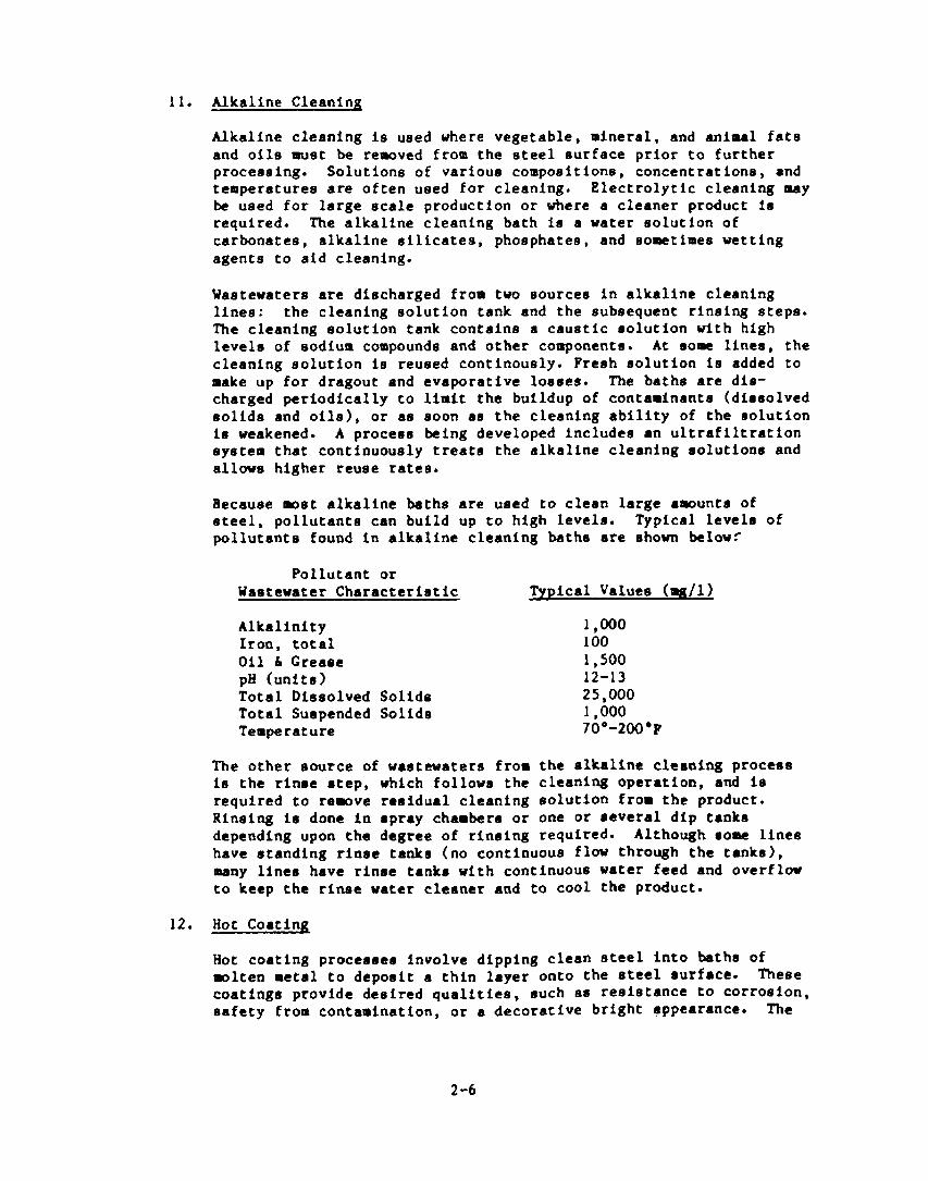
Alkaline cleaning is used where vegetable, mineral, and animal fate and oils must be rewved from the steel surface prior to further proceaaing. Solutions of various compoeitions, concentrations, and temperaturea are often used for cleaning. Electrolytic cleaning pray
be used for large scale production or where a cleaner product is required. The alkaline cleaning bath is a water solution of carbonates, alkaline slllcatea, phosphates, and sometimes wetting agents to aid cleaning.
Wastewaters are discharged from two sources in alkallne cleaning lines : the cleaning solution tank and the subsequent rinsing steps. The cleaning solution tank contains a caustic solution with high levels of sodium compounds and other components. At some lines, the cleaning solution Is reused contlnously. Fresh solution is added to make up for dragout and evaporative loeaea. The baths are dia- charged periodically to limit the buildup of contaminants (dissolved solids and oils), or a8 soon as the cleaning ability of the solution la weakened. A process being developed includes an ultrafiltratlon ayatem that continuously treats the alkaline cleaning solutions and allows higher reuse ratea.
Because wet alkaline baths are used to clean large awunta of steel, pollutants can build up to high levels. Typical levels of pollutants found in alkaline cleaning baths are shown belowr
Pollutant or Wastewater Characteriatlc Typical Value8 (mg/l)
Alkalinity 1,ODo Iron, total 100 Oil 6 Crease 1,500 pEl (unite) 12-13 Total Dissolved Sollda 25,000 Total Suspended Solids 1,000 Temperature 70’-2OO.P
The other tsource of wastewaters from the alkallne cleaning process I8 the rinse step, which follows the cleaning operation, and is required to rewve residual cleaning solution from the product. Rineing is done in spray chambers or one or reveral dip tanks depending upon the degree of rinalng required. Although l oae lines have standing rinse tanks (no continuous flow through the tanks), many lines have rinse tanks with continuous water feed and overflow to keep the rinse water cleaner and to cool the product.
Hot coating proceeaea involve dipping clean steel Into baths of wlten metal to deposit a thin layer onto the steel bufface. These coatings provide desired qualitiee, such as reeistance to corrosion, eafety from contamination, or a decorative bright appearance. The
2-6

two major classes of mtalllc coating operations In the industry are hot coating and cold coating. Zinc, terne, and aluminum coatings are wet often applied from molten metal baths, while tin and chromium are usually applied electrolytically from plating solu- t lone. Nearly all hot coating operations discharging to POTUs use the galvanizing process (zinc).
The major wastewater flows originating from hot coating operations fall Into three groups:
l Continuous dilute wastewatere from rinses following chemical treatment or surface paeslvation steps and final product rinses after hot dipping. These water8 contain suspended and dissolved solids, chlorides, sulfates, phosphates, elllcatee, oily matter, and varying awunts of dissolved metals (iron, zinc, chromium, lead, tin, aluminum, cadmium) depending on which coating metal Is used.
s Concentrated Intermittent discharges (including fluxes), chemical treatment solutiona, and regenerant solutions from in-line Ion exchange systems. These discharges contain higher concentrations of the pollutants noted above. Discharge volumes from these sources can be minlrized by close attention to maintenance and operating conditions, and by using dragout recovery units. Hot dipped coating bathe themselves are never discharged. In8 tead, they are recovered and continuously regenerated as part of the coating operation, or by outside contractors.
l Fume scrubber wastewaters are produced by the continuous scrub- bing of vapors and mists collected from the coating steps. Scrubber wastewaters may be used as process rinses, since only volatile components are present in the air to be scrubbed. Less than 40 percent of all hot coating lines have wet fuPe scrubbers. A few plants have dry fume absorbers.
Many of the subcategories were further divided to account for differences
in manufacturing procereea and equipment. Separate limits were then developed
for each subdlvlslon.
2.2 PRETRRATFIENT STANDARDS FOR THE IRON AND STEEL MANUFACTURING CATEGORY
The categorical pretreatment standards for the Iron and steel Industry
dlatinguish between exleting sourcee and new sources. As a general rule, EPA
establiahe8 pretreatment standards on the basis of concentration. However,
for the rteel industry, the Agency bellevee the standards should be based upon
mesa limltation8 (kg/kkg) to ensure that effective toxic pollutant control is
provided and to minlnlte the hydraulic impact of large volume discharges on
2-7

POTUS. These standards are expressed as maximum 30-day average and maximum
dally mass llmftatlons in kilograms per 1000 kilograms (lbs/lOOO lba) of
product (except for acid pickling and hot coating operations with fume
scrubbers where mass limitations are expressed in kilograms per day for each
scrubber).
The pretreatment standards for existing sources (PSES), with the excep-
tion of cokemaking, are equivalent to best available technology (BAT) for
direct dischargers. BAT represents the wastewater treatment processes
necessary to achieve best available economic performance of wastewater
treatment at plants of different ages, sitea, production rates, and other
factors. The standards for cokemaking facilltles are based on treatment
technologies installed to pretreat cokemaking wastewater prior to on-site
biological treatment. These levels of treatment include technologies for
removing toxic pollutants, both by process wdlflcation and by end-of-pipe
treatment , which could parse through or otherwise be incompatible with the
operation of a POTU. Pretreatment standards have been developed by EPA for 10
of the 12 iron and steel subcategories. The two eubcategorles which do not
have pretreatwnt standard8 are Subpart G - Hot Forming and Subpart K -
Alkaline Cleaning. For these two subcategories, EPA has determined that there
are not significant quantities of toxic pollutants to upset or pass through
PO’fW treatment plants or limit POTU sludge management alternatives. For the
10 regulated subcategories, the limits are presented in Tablee 2.1, a-f.
The pretreatment standards for new sources (PSNS) apply to iron and steel
manufacturing facllltles for which construction began after January 7, 1981,
the date of the proposed regulation. New facilities are able to incorporate
process controls that reduce pollutant loadings, so in come cases the PSNS are
more stringent than PSES. The PSNS are based on the beet available demon-
strated technologies and for wet subcategories are identical to the PSES.
The exceptions are: Subpart I - Acid Pickling, Subpart J - Cold Forming, and
Subpart L - Hot Coating. The PSNS for these three subcategories ate presented
in Tables 2.2, a-f.
2-8

rnEtUlllmlT STANCURDS ror KxtsTIE SOUIUS (Pscs)
POUIJTAJIT LlNlTs (la kg/K&g of pro&cc umlea* 0rhen1.0 nocod)
s&part Pbonol llxpbtba- Tetrachloro- Cyoalk tbxxroIoar
-1x Cblorloo (hAr) Len l thyA.0. Chralvr (Total) Lad YLcLcl Zinc Cbraium
&. cukutly 1. ICM wd SCWll ho. 0.0122 0.0215 0.00159
wax. 0.0645 0.043 O.OL72
2. krchut2 Avm. 0.0315 0.025 0.0100 ka. 0.0751 0.0501 0.0200
B. Sl*t~rly’ AW. 0.00501 0.oooo501 0.00150 0.ooo150 0.000225 Max. 0.0150 0.000100 0.00300 0.000451 0.000674
C. Iroahklry Irw *v*. 0.00292 0.0000292 0.000@16 O.OtXJO616 0.0001 II
kx. O.OWlb O.OOMM4 0.00175 0.000263 0.000394
?.rr0-
uplUW.*
0. Ito* ldle# 1. maslc osygu
hruu (roP)c kri- ut*
2. DOP: uot-opom AVO. O.OOOlY 0.oOO201 uu. o.oocM13 o.mo620
3. Bw: uot- b*. O.Oooo62b o.OOoo939 wppmood nax. 0.ooo1u 0. ooo282
2-9

TABLK 2.lb
PNfTIM’TwwT STAllDMDS 1011 EXlStt~ !%UXC@!Zi (PStS) (Contfnued)
wLuJTu(t LflllTS (In CSfrkS of product unleso otherufse noted)
subpmt
Phenol naphtha- ret rachloto- Cyanide Ntrav~lcnC tinta Chlorlar (QAP) ltne ethylene Chraluo (Total 1 LLad n1ctc1 ZlOC cbraluo
5. Il0ctrlc Arc Purnoco UN): kalwt*
6. UP: u*c AW. 0.omluI 0.00020~ MU. 0.oow13 o.ooo62o
K. VW- AVO. o.aMo311 O.moo669 oegumiy hx. o.OooO939 O.ooa14L
r. Comt1muouo Ave. 0.0000111 O.OOOOb69 comt l*I au. o.oom939 0.ooo161
C. Not ?ormly**
4. OxldlrIng - 1. Batch. Sheet Ave.
sod plate Mu. 0.00117 O.WO616 0.00292 0.00263
2. Satch. Rod Ave. 0.ooo701 0. WO526 od Ylro ks. 0.00175 0.0015I
3. Such. ?lfm Ave. 0.00216 0.002I3 sod Tu’ubr Hal. 0.00709 0.006M
4. CO*ttWOW h*. 0.000551 O.ooo6l3 ka. 0.001 M 0.00126
A**. 0.000512 0.0001l9 0.wo607 nw. 0.00136 0.00102 0.00122
2. Cont I wou, Art. 0.00304 0.00190 0.0022lJ kx. 0.00159 0.00569 0.00683
2-10

TAAU 2.1~
PUTMA- STUlOUDS IOI KXLSTINC !XUCCCS (PSRS) (Coatlnud)
PtlLlVIUlT LlnITS (in 4/Kkr of product ~18~ ocbond~8 noted)
Subpart ?hOIbol Naphtha- Totrachloro- Cyanid neruvalsnt
-la Chlorlv (4Au) 1.M l tbylorm Chrodur (Total) Load WlCk.1 zinc chrom1ur
I. Acid ?lcklly 4. Sulfuric
Acid ?lckllag - 1. bd. Wm. Ave. O.oabl75 0.000234
od coil nu. 0.000526 0.ocK4~01
2. hr. Slllet. Ave. o.OwO563 o.oaOlu51 ad Bloa lbl. o.mlL9 O.ooO225
3. Strip. AU. 0.m1 I3 0.Ooul50 shut , @Iax* 0.000339 0.000451 ad wat*
4. ?lpe. Tub., Ave. O.oOo3l3 O.UOO411 4 Otbor ka. o.Qoo93m 0.00125
5. Irw Scrubber’ Ave. 0.0123 0.0164 (kg/&y) max. 0.0368 0.0491
b. Mydrochlorlc &Id Plcklly - 1. Knd, Ylra. AV8. O.OUOM? u. ow409
od 42311 lla8. o.Ooo92o 0.00121
2. Strip. --t, Ave. 0.000115 0.000214 J r1ato lamx. 0.000526 0.oou101
3. ?lpm, Tub., Avo o.wob38 O.ooo651 nd Other Itax. 0.00192 0.00255
4. ?w Scrubber’
Ave. 0.0123 O.UlbC km. 0.0368 0.0491
5. Acid Be- Art. ~totrmr loo6 k8.
0.0819 U.lU9 0.245 0.012/
(*bBorbtr vent scrubber 1 (kI/dAY) 2-11
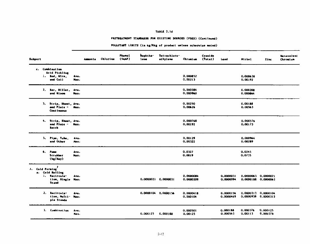
TABU 2.Ld
~RcTMA~cI~T ST*wDuW IOI EXiSTlm; SOURCU (PSCS) (Comt1nu.d)
POLLUTANT l.lHtTS (la kg/Us of prodact unleoa orbonl~~ noted)
Subpart tbam 1 !lqhtha- Tat rachloro- Cyamlda nexavaleat
*ronla Cblorlna (UN) 1.m ethylma c?lhrorlur (Total) Lead Ylckal ZlfU Chratur
c. cooblutloa Acid Plckllag
I. Rod. Ylrm. Ave. 0.000952 0.0006M ond Coil h. 0.00213 0.00192
2. Bar. Btllar, Ave. 0. ow384 0.ow2.0 and Bloom #Ia=. 0.0009bO 0.WO.W
3. Strip, Shot, Ave. 0.00250 O.WlM ud mat. - Mu. 0.0012b 0.00563 coat lmuou~
4. Strip. Shut. Ave. O.OW?M 0.00057b l d Plato - kx. 0.00192 0.001~3 kCCb
5. Pipe. T&R, Ave. 0.00129 0. ooo9b4 and Otbm ks. 0.00322 0.00219
Ava. 0.0327 0.0245 nan. 0.0819 0.0735
.I. Cold PormlaS’ . . Cold RolllnS
I. Iocltcula- Ave. Clam, Slyle ltmx. stmd
O.OOOOO84 0.oOOoO31 o.OoOm63 o.aNaOo21 o.anKN321 0.OOOm31 0.OOOo209 0.m 0.OoOo1M o.amO63
2. Roclrcula- Ave. 0.m104 O.OOoQl56 O.oaOO4lI 0.0000156 0.OoOO313 0.m104 Cloa, bltl- max. 0.000104 0.0000169 o.oooo939 0.oOoO313 plo scan&
I. Curblnac Ion AV. O.OwMJl 0.0001S4 O.ooO37b O.WO125 maa. 0.000125 0.ooo198 0.00125 0.000563 0.001l3 O.OOU376
2-12

TUU 2.h
-TlWlfT STUDUW IOI CXISTIE SOUyEts tPS#S) (b~t1m.d)
mLvtyn Lll(lTS (lm kg/Us of product ulom othorr100 noted)
Subart tin01 nqbtha- Totrachloro- Cyul1& nouva lomt
*roala Chlorlw (4AM) 1.0. l thyh8# Chralv (Total) Iad Mlck.1 Xlnc Cbralvr
4. Olrmct Appllcstlom. Am. 0.m150 o.Oooo563 O.ofJoI I3 O.Oooo376 SlR#lO nox. O.oooo316 o.oooo543 O.ooo37b O.ooo169 o.ooo338 0.aIO1 I3 stnd
5. Dlroct A-. O.WObM 0.000250 O.WO501 0.ooOlbl 4ppllcatlom. ka. 0.000161 o.wo25o 0.00167 O.o00?51 0.00150 0.000501 lblt lplo Btud
b. Cold Uorkd ripa #d hk tllllr
I(. AlkalIno c1*u1a#**
L. mot rawlm# . . calrul~l~ Ave. O.OW31b O.WOW 0.amo501
am4 Orbar umx. O.Wl13 O.Wl50 O.WOlY) Co~Cl~ - Strip. Shot. l d ltlac.
b. calvul~ly - Ave. O.Wl50 o.w2w o.ooo2oo Ylra Pro&em nos. 0.00451 O.oowl 0.ooo6o1 04 Putomro
c. Pur krrbbro (kr/day)
A-. 0.0123 O.OlU 0.00163 noa. 0.03bLI o.oI91 0.00490
Ava. - Averqo of dally vmlwo for 30 co~~c~tlvo daya ka. - kale for uy oy day
)Ttrim~imtvtomnfd.

TABLE 2.lf
PUTUATlWfT STANDARDS IOU KXlSTINC SCWKCS (PSCS) (Conttnuad)
1 Iocreuod lod11~0, not to exceed 24 porcoot of thaa l taadarda, art l llwod for by-product coke plonta that have uot dtmlfurlr~tloo l yrtcr, krt only to tbm utoat that ouch l yotor gtnorato oo lncroaood l fflwnt volume. Incrouod loadlqe, not to oxcood M porcoat of theme l rmdarda, are l llouod for by-product coke planta that bare idlroct -14 rocovory l yotomo, but only to tho oxtent that ouch l yrtm powrat an increamed l fflunc volur.
2 Imcromod 141-o. not to oxcood 21 porcomt of thro l tandarda are l llowd for by-product coke plaatm that have uot dosulfurlcatlon l y#tou. hut ooly to tbo l stont that ouch ayam aoaorato a lmcrooood effluent vole. Incroaood Loadlngo, oat to l mcoed )o percent of theme l tmndardm, arm l lloumd for by-pm&cc co&o plaoto that bare ldlroct -la rocovory l yotom, but only to tbo oRtent that ouch l yatea ~ooororo an lacreaood offluont vol\w.
3 Ibo l tmdordo for -lo+, cyoolb, omd pboaols (4Au) are l ppllcablo only tiea l lnrorlnS uastouator lo treated along vlrh ironmaking waatowotvr.
4 Tbooo llmlto apply to each flrr rcrubbor l ooocIatod ulth l ulfurlc l ctd plckllrq oporatlomo.
5 Thomo llmlto apply to each fuu l crubbor uooclatod rlth hydrochloric acid plckllng opormtlonr.
6 Woo llmlto apply to aboorbor root l crubbor uwtouacor l oooclatod rlth bydrochlorlc acid regoooratloo planto.
lor procooaoo roaulatod by Subport J, rho llmltr oo chromium and nlckol apply lo llou of the lloltr oa led and slnc mboa cold rolllly wastvuat8ra vro trmtd rlth &ocallq or cdlnatla wld plckllly water..
B Dlwhargoo frm thou operatlonm to habllcly md Treatrnt York. l rm prohlbltod.
2-14
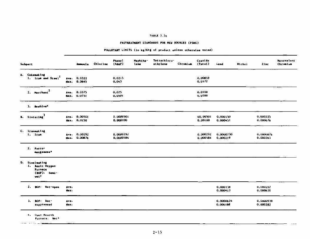
TMLP 2.2a
PYETfU!ATIffUlT STUIDAllNi Iw MU SWIUZS (PSUS )
POLU~TANT LIMlTS (In kg/Kka of pru&cKt unltmm otherulo. noted)
Subpart Ph*OOl hphLhC T.t r.chloro- CyanId. IkXAVAl~llL
tile Cblor lly (SAAF-1 18lw l cbylona Chromlm (Tor.1) 4.d Ylcktl Zinc Chralum
A. COkOOOklpI 1. lroo end St-l’ Ave. 0.0322 0.0215 0.001)59
naa. 0.0645 0.043 O.Ul~2
2. ltercbat2 AVO. 0.0315 0.025 O.OlW ka. 0.0751 0.0501 0.0200
3. B..hl vd
B. Slmr*rlmg3 AV.. o.w501 O.WWMl uO.Wu)l o.awlw O.ooo225 flu. 0.0150 0.ooo1w 0.00100 0.ooo451 O.OUOb?b
C. lroauklnc I. lroa Ave. 0.00292 O.WW292 0. My)292 O.WW?M O.wwU1b
kx. O.otm?6 0. oooo544 O.ooO% O.WO219 O.OW263
2. Perro- ~&l~NhOU~
D. SL..lm&1~ I. Bulc Oxy#on
lurnaco (aoP)G soml- wet’
2. mp: Yet-op8n AV.. 0.w13LI U.WUlU? Hex. 0.ow411 O.WfmZO
3. Boot: umt- AV8. O.WW626 o.cinnEa39 l 94ppremoed )(u. O.OOUlfld 0. Wo2a2
4. Open Hearth Purntct: utt*
2-15

TABU 2.2b
RETREATWWT STANDARDS 1011 YtY SODRCJ!S (PSNS) (ContImed)
PIXLUTANT LIMITS (In k#/Kk# of product unleae oLhorula8 noted)
Subport Pheno 1 Nephthe- Tot r.chloro- Cyoddo N.a~vm10.L
-1. Chlorln. (4cwl 1elU ethylon. Chralw (Tot.1) b.d Nlck.1 Zinc Chralur
5. Ilectrlc Arc Puruce (WI: sod-umt*
6. w: uot A-. 0.000139 0.ow207 hex. o.OW413 o.wob2o
K. VoclBum Ave. o.mOO313 0. ooOo469 Do~00. 1y nu. o.Oom939 0.000l41
1. cortl- Cut1y
c. not PotnlyH
AVO. o.WW313 O.oOoD469 Max. o.oow939 O.cNJoL41
Y. Salt math oooully
. . Oaldlrly - I. Botch, Soot Ave.
mod ?1*t. nu. O.Wll7 0.000876 0.00292 0.00263
.I. Bmtcb. bd Ave. o.a30701 O.OW526 mmd Ulro Mea. 0.00175 O.Wl5I
3. Botch. l lpa AN. 0.00284 0.00213 ad Tub Roa. 0.00709 0.00638
4. Cortl- Ave. o.Wo551 o.Wo413 kx. O.WlM 0.00124
b. IeducIng - I. Bet CL Ave. o.WO542 0.000339 0. ooo6Ol
Il.=. O.Wl36 O.WlO2 O.Wl22
2. CodfwoM Ave. o.w304 O.Wl90 0.00228 ka. O.Wl59 0.00569 0.00683
2-16

tau 2.2c
-m stAnMRDS m luu sou8us (rsus) (c4aar1nued)
PoLlmAut Llnlts (lo kg/UC of product rul.~~ 0thorutB. OoCd)
tieno 1 UBphthB- tat rachloro- CyBUl& lkruvBlent konh rnlorlm (u&t) LBnB l chylem rnrau (lord) Leti YlCk~I Zinc mhr0dur
I. AC14 Plcklly . . Sulfuric
Acid Plckllrq - I. Eod, Ylra, AW. O.UOOO3ll O.cxKnL17
l sd co11 b. o.wM3939 O.oooL25
2. Bar, 1111at, Ave. O.oooO18C 0.owo250 ad gloom k8. 0.0000563 O.UOOO75L
3. Srrlp, Are. 0.ooOO250 lLa300334 Stuot, aax. O.oouo?5~ O.CWJLoO Bed PlBU
4. ?lpe. t&B, Are. 0.000013ll o.OOoO584 ~4 Qber ibaa. o.ooo131 0.000175
5. lun Serubbac' 4ro. (kg/&y) kx.
0.0123 O.OLb4 0.03bc 0.0491
b. Yydrochlorlc Acid ?lcLlly - L. Cod. Yirm, AVO. O.UOOO37b O.UOOO5Ul
Bad ceil mm. 0.000113 O.OOCU150
2. Strip, abet, Ave. 0.0000250 u.m334 Bd rIBto kl. o.oooo751 O.ooOloO
3. ?lp. tube, Avm O.UOUObU O.OUOO918 Bad OtbBr ka. o.ooo2Oh 0.000275
4. vuou Scrubber 5
Ave. 0.0123 0.0164 ha. o.o%a 0.0491
(L#/dBf)
2-17

hem I Uaphtha- Totrachloro- Cyanide lbxavalont -18 Cblorlw (WI l*w l tby1.u Chrorlur (Total) kad NLckel Zlac Chralu
c. CombIutla &cl4 ?1cklly
1. W, Yiro. Avm. O.omll7 O.OOOtM?tJ d co11 au. 0.000292 0. ooo263
2. asr, Billet, Am. O.oOOO667 O.WClO5Ol ad Bloa ha. O.om167 O.ooOl5O
3. Strip. Skeet, ha. 0.#0284 0.000213 aad Plate - lhx. o.oOO71o 0.000638 brhaame
4. Strip, Sheet, ti. O.OOOlOO 0.oom751 aad r1at* - *u. o.ow25o o.ooo225 kCCb
5. l lpm. Tub., Am. 0.ooo167 O.ooOl25 aad Ocher ka. O.OOCbbI8 0.000176
Ave. 0.032 7 0.02b5 au. 0.0819 0.0735
J. cold lO”‘mS a. cold billy
1. Smclrcml*- Am. O.fJOCKKW O.OOOOO31 o.OOooo63 O.OOooOZL Clam, SlmSl* Ilu. 0.OwoO21 0.Oam31 0. oOaI209 O.OOOOO94 0.oom18a o.cmmo63 ttnd
2. Recirculs- Awe. O.cmOo167 o.cmooO63 o.aMO125 o.oamo4z 1101. rltl- awa. O.oomo62 o.ooOaM3 0.00004l8 0.000018R O.owO376 O.oooOl25 pla St&
3. Combimatla Ave. 0.000217 0.00008I4 0.000163 o.oOoOu2 ma. o.oooO542 O.oaMMI 3 0.000543 0.000216 O.ooO48R 0.000163
2-16

&WI llaphtha- Tet rachloro- CYWl& nasaval*nt ata Qloclu (urr) 1.M l c hy lwo hramlwm (Total) lad IlChl Zlac Chromlrw
4. mm ~llculr. Ave. O.OOW418 0.0000156 0.Oooo313 0.oooo104 a1al.m Ilu. 0.oooo104 O.ooaOLsI 0.om106 0.0000469 0.0000939 o.oaIo313
5. D1ru.t Am. 0.000484 0.000182 o.ooo363 0.000121 Appllcrla. Iha. 0.mo121 O.WO182 0.00121 o.ooo545 0.00109 0.000363 lhll IpI. scad
I(. Altd lr Clmalap
L. Mot cootl~ 4. cdvwlsly AVO. o.aum39 o.wQ121 0.oooo125
d Otbmr *u. O.ooO282 O.OaJ37b O.OWO376 coattym - Strip, Shot. aad lItme.
b. calvulal~ - Ylm ho&eta nd ?wtomn
AVO. O.ooo376 0.00050 0.oooo50l km. 0.00113 0.00150 0.0041w
c. I- A-. 0.0123 0.0164 0.00163 &rob&r0 ha. 0.0368 0.0491 0.00490 (U/day)
2-19

TMU! 2.21
PUTRKATiUNT STAftMlDS FtM NW SOUWf!S (?SftS) (Cont1ou.d)
1 Incraaeed loadla8., not to exceed 24 percent of the.. l tendarda. l re allwed for by-product coke planta that have wet deeulfurlzatlon ryateu, but only to the extent that much my&au gwbat~ra aa Lacreued l fflwnt volu. fncreued 14logm. nat to exceed 58 perceot of thea. l taodard.. are allowed for by-product co&e plant8 that heve Indirect IYI~ recovery l yotm, but only to tb l rtont that l uch eyetea Bowrate an increemed l fflwnc voluw.
2 lwteaoed l~dllym. oat to l xcwd 21 percent of the.8 rtaadwdr are l llowed for by-product cob. plant. that have uet deeulfurlz~tlon l yeteu. but only to ttu l mt*nt tht aach l yotom s*nor*t* aa lacreuod l fflunt volu. lacreued loadllya. mot to l xcwd 50 percent of there l tendardr. l re allowed for by-product co&e plamta that bar. Iadtrect -ia recovery myatom, but only to the ertent that l ucb ryotor generate l n Increased effluent volu.
3 Tb. rtandardo for -la-If, cysald., and pbenolr (4W) l re l ppllcabl. oaly Aen rinterlly uaeteuator 1. croated along with lronuLln# weceuater.
4 l?uee llrlro apply to each fu l crubbor l @ooclated with mulfurlc @cl6 picklIly operatloae.
5 Tbeoo limit. apply to each fur scrubber l .eoc1at.d uIth hydrochloric l cld plcklinl owratlona.
6 yor proceeeea regulated by Subpert J, the lflltr on chromlu. and nlckol apply In lieu of tha lialt~ on lead snd rlnc when cold rolling w~etoweter. are tr**td rlth drscally or combllutloa l cld plcklin8 uatoro.
7 Dlmchr8eo from theoe operatloo. to yubllcly md treatwnt York. l re prohlblted.
2-20

2.3 REUTImIP To ELECIFOPIATINC AND METAL FINISHIK;
In certain cases there may be sane question regarding whether a
production process is cuvered @ Iron and Steel Categorical pretreatment standards or Metal Finishing pretreatment standards. For iron and steel manufacturing operations also covered by metal finishing, the ~y)re specific standads apply, i.e., iron and Steel.
For example, if a plant perfollae pickling artd electqlatiq at an iron iyd steel then the metal finishing PSES apply only to the discharge fran electrqlatirq while the iron and steel PSES apply to the discharge fran the surface preparation operation of pickling. Normally, the metal preparation cperation (picklifq), would be subject to the metal finishing regulation, hawever, because the iron and steel regulations specifically include this operation performed in iron aml steel mills, the iron and
steel regulation takes precedence for this wastestrem.
The EPA excluded frm relation 81 of the 126 toxic pollutants that are given priority consideration. These pollutants are famd either in a small nunber of sources and are uniquely related to those sources, or are detected in the effluent in trace quantities, which are not likely to cause toxic effects. These 81 pollutants am presented in Table 2.3.
2.5 CQQLIANCE IXf’ES
In aazordance with the settlenent agreerbent, all existing irrbstriea engaged in the manufacture of steel mst cmply with the Iron and Stem1 Ca tegorlcal pretreatment sbndards, by July 10, 1985 except for thee
facilities identified in the regulations as being considered under 6eparate
ruler&&q for central waste treatment facilities. All new steel manufacturing facilities mat canply with pretreatment atam%3n3s at tb
time dischaqe ammmnces.
2-21

TABLE 2.3
POLLUTANTS EXCLUDtD ?ROkf IRON AND STEEL REGULATION
Pollutant Unique Trace
Occurrence Qusntitiee
1,2-Dfchloroathme 1,1,2-Trlchloroethmc 1,1,2,2-Tattochlorotthane 2-Chloroarphthrlrnr 2,4,6-Trichlorophrnol 2-Chlorophenol 1,2-Dichlorobenzenr 1,4-Dichlorobeazenr 1,1-Dichloroethylenr 1,2-Trmedichlororthylene 2,4-Dichlorophenol 1,2-Diphenythydratene Methylenechloride Dichlorobromomethane Iaophorone Nit robenzene 2-Nitrophcnol 2,4-Dinit rophenol 3,4-Bentofluoranthene Benzo(K)fluoranthene Benzo(ghi)prrylene Dlbenzo(a,h)-anthracene Indeno(l,2,3 cdjpyrene Vinyl Chloride Aldrin Dledrin Chlordane 4,4-DDT 4,4-DDE 4,4-DDD a-endorulfaa-Alpha b-endorulfan-Beta Endorulfan rulfate Endrin Endrin aldehyde Heptachlor Heptachlorepoxide r-BHC-Alpha b-BHC-Beta r-BHC-Carra g-BBC-Delta PCB-1242 ~~~-1254 PCB-1221
X X X X
X X X X X X X X X X X X
X X X X X X x X X
X X X X X X X X X X X X X X X X X X X X X X X X X X
2-22

TABLE 2.3
POLLUTANTS EXCLUDED PROM IRON AND STEEL REGULATION (Continued)
Pollutant Unique Trace
Occurrence Quantfties
PCB-1232 PCB-1248 PCB-1260 PCB-1016 Toxaphene Beryllium Mercury Manganese
X X
2-23

3. TREATMENT TECHNOLOGIES
The treatment technologies described in this sections are currently used
by iron and steel manufacturers to remove wastewater pollutants generated by
industrial processes. The technologies are grouped according to the subcate-
gories where they are used, and include oil skimming, metals precipitation,
sedimentation, steam distillation, solvent extraction, thickening and vacuum
dewatering.
3.1 TREATMENT OF COKEMAKING WASTES
Treatment of wastewaters from this subcategory can be accomplished with a
system such as that illustrated below.
With this system, process wastewaters are mixed with waste ammonia liquor
and enter a dephenolizer, which recovers phenolic compounds. The benzol plant
wastes and final cooler blowdown are initially treated In a gas flotation unit
where waste pickle liquor is used to break emulsions and an inert gas mixture
Is introduced to enhance the separation of oils and greases. The above two
waste streams are then combined, free ammonia is stripped and recovered and
lime or caustic soda Is added to raise the pH to 11 or 12. Fixed ammonia
stripping is used to remove as much ammonia as possible prior to further
treatment. Wastes are then retained in an equalization/sedimentation basin
with approximately one day’s retention time. Unreacted lime particles and
other suspended utter separates out, and is periodically removed by clamshell
bucket or transferred to vacuum filters. The overflow from the basin is then
neutralized and aerated prior to discharge to the POTW.
3-1

3.2 TREATMENT OF SINTERING WASTES
Sintering process wastewaters result from dust and gas scrubbing equip-
ment and from sinter cooling. The common practice is to combine wastewater
streams for treatment. A treatment system suitable for meeting pretreatment
limitations for this subcategory is diagramed below.
With this system process wastewaters enter a thickener where oils and
grease are removed by skimming and solids are settled with the aid of a
polymer. Sludge removed from the thickener is dewatered on a vacuum filter.
Ninety-two percent of the thickener effluent is returned to the process.
Wastewater is discharged from the system after pressure filtration or metals
precipitation.
3.3 TREATMENT OF IRONMAKING WASTES
Prior to the mid-1970s, treatment of Ironmaking wastewaters involved
removal of suspended solids by sedimentation, aided by flocculating agents to
Improve removal rates. These clarified wastewaters were discharged without
further treatment. Today, about 90 percent of blast furnace wastewater
treatment systems include recycling (after the thickener), and discharge only
a relatively small percentage (generally 5 to 10 percent) of the process flow.
Cooling towers are often used to lower the temperature of recycled waste. The
3-2

thickener underflow are typically dewatered with the filtrate returned to the
thickener Influent. The devatered solids are either sent to sfntering
operations or to off-site diSpO8al. A typical wastewater treatment system for
meeting pretreatment regulations is diagramed below.
In addition to the eollds removal and recycle technologies, treatment
fncludes a two-stage chlorination process to destroy cyanide and to oxidize
phenols and amonia. Followlag chlorlnatlon a reducing agent such as sulfur
dioxide Is added to remove reeldual chlorine.
3.4 TREATMENT OF STEELMAKING WASTES
Uasteuatcr treatment for discharge8 from this subcategory can be accom-
plished with a system such as that diagramed below.
(1) Rccych rates: 95% - Bssic Oxygen Furnace - Swpmsscd Zxbustion
9OS - Basic Oxvaen furnace - Own CocnbuStll

Waatevater initially enter. a thickener, uhich reducer l u8pended solids
with the aid of a polymer or other coagulant aid. The rolidr are reroved and
thickened on 8 vacuum filter. A rujor portion of the effluent from the
thickener 18 recycled to the procesr; the remainder flova to an inclined plate
separator after lime is added for removal of toxic metals.
3.5 TREATMENT OF VACUUN DEGASSING WASTES
A waatevater treatment syrtem capable of meeting pretreatment regulations
for this subcategory is dimgraDed below.
mn
The firrt rtep in the pretreat-at process lnvolver gravity sediwatatloa
in a 8Cale pit to remove l uapended rolidr. The effluent from the scale pit
flour to a sump and la either recycled to the procers through a cooling tOuer
or ia treated with liw to precipitate metalr. Wartewater is discharged after
solids and toxic rstals are removed by lime preclpltatlon and clarlflcatlon In
an inclined plate separator.
3.6 TltEARIBHT OF CONTINUOUS CASTING WASTES
The pretreatment rtandards for this rubcategory can be mt using the
treat-at syrtem diagramed below.
3-4

scale plt (process wrsteurters)
The process wastewater first enter a rcale pit where solid8 are removed
by sedimentation and oil la skimed. A flat bed filter Is then uaed for
additional solids removal (a prerrure filter ir recomended for meeting PSNS).
About 96 percent of the filter effluent la returned to the procerr; the rest
is treated with lime to precipitate metal8 la an inclined plate reparator.
3.7 TR&AMNT OF HOT POBnINc WASTES
About 20 hot forring operatioar discharge uartewaterr to POTUs. In many
cases, theme wastewaterr are racycled to mlnlmlze uaer fear to the industry
and to avoid hydraulically overloading POTWe. EPA bellevea that future
discharges to POlWa from hot forming operationa, if any, will recefve slailar
treatment and will not contain high levela of toxic mtalr. The Agency
believes that the pasr-through of toxic pollutant8 from hot forming operations
Is not a problem. Thus, categorical pretreatment standards for hot forming
wsetewaterr were not promulgated.
3-5
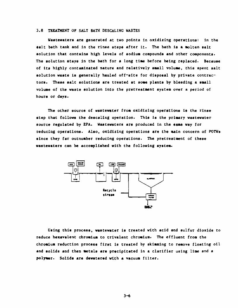
3.8 TBBATHENT OF SALT BATH DESCALINC WASTES
Wastewaters are generated at two points In oxldltlng operations: in the
salt bath tank and in the rinse steps after it. The bath Is a molten salt
solution that contains high levels of sodium compounds and other components.
The solution rtaye In the bath for a long time before being replaced. Because
of its highly contaminated nature and relatively small volume, this spent salt
solution waste is generally hauled off-site for disposal by private contrac-
tore. These salt solutions are treated at some plants by bleedfng a small
volume of the waste solution into the pretreatment system over a period of
hours or days.
The other source of wastewater from oxidlzlng operatlone is the rinse
step that follows the descallng operation. This Is the primary wastewater
source regulated by EPA. Wastewaters are produced In the same way for
reducing operations. Alro, oxldltlng operations are the main concern of POTUs
since they far outnumber reducing operations. The pretreatment of these
wastewaters can be accomplished with the following rystem.
Using this process, vaetewater 1s treated with acid and sulfur dioxide to
reduce hexavalent chromium to trivalent chromium. The effluent from the
chromium reduction process first Is treated by skimming to remove floating oil
and solids and then metals are preclplt8ted In a clarifier using lime and a
polar. Solid8 are deuatered with a vacuum filter.
3-4

3.9 TREATMENT OF ACID PICKLING WASTES
The system described below is capable of meeting PSES. A more complex
system would be needed to meet PSNS.
The eeveral waste stream are combined la an equalltatlon tank where oils
are eklacd. The wastewater is then treated with lime and a polymer and
aerated to oxidize iron from the ferrous co ferric state. Next, it enters a
clarifier to aettlr out solids and toxic metals, which l ra dowatered on a
vacuua filter.
3.10 TREAI?IENT OF COLD ROLLING WASTES
Treatment of waateuatarr from thir subcategory can be met using the
following system:
3-7

The treatment process includes 011 removal and solids removal. Floating
oil is removed, then alum and acid are added to break emulsions. Solids and
oil are removed by air flotation following lime and polymer addition. A
vacuum filter is used to deuater sollds.
3.11 TREATHENT OF ALKALINE CLEANING UASTES
Wastewaters from alkaline cleaning operations are relatively clean
compared to waetewatera from other steel industry operations. Toxic pollu-
tante are present in untreated alkaline cleaning wastewater only at levels
below or near treatability levela. EPA has not promulgated numerical pte-
treatment standards for this subcategory.
3.12 TREATMENT OF HOT COATING WASTES
Pretreatment of galvanizing wastewaters can be achieved with a syntea
similar CO that discussed under waste treatPent for the Salt Bath Descaling
subcategory.
3-8

4. REQUIREMENTS OF THE GENERAL PRETREATMENT REGULATIONS
4.1 INTRODUCTION
The section provides a brief overview of the General Pretreatment Regulations and identifies those provisions of the Regulations that have a direct bearing on the application and enforcement of Categorical Pretreatment Standards for the Iron and Steel Manufacturing category.
The General Pretreatment Regulations for Existing and New Sources (40 CFR Part 403) establish the framework and responsibilities for implementation of the National Pretreatment Program. The effect of 40 CFR Part 403 is essentially three-fold. First, the General Pretreatment Regulations establish general ad specific discharge prohibitions as required by Section 307(b) and (c) of the Clean Water Act. The general and specific prohibitions are described in Section 403.5 of the Pretreatment Regulations. they apply to all nondomestic sources introducing pollutants into a POTW whether or not the source is subject to Categorical Pretreatment standards.
Second, the General Pretreatment Regulations establish an administrative mechanism to ensure that National Pretreatment Standards (Prohibited Discharge Standards and Categorical Pretreatment Standards are applied to and enforced against industrial users. Approximately 1,500 POTWs are required to develop a locally run pretreatment program to ensure that nondomestic users comply with applicable pretreatment standards and requirements.
Third, and most importantly for the purpose of this guidance manual, the General Pretreatment Regulations contain provisions relating directly to the implementation and enforcement of the Categorical Pretreatment Standards. They include the combined wastestream formula, reporting requirements, local limits, monitoring or sampling requirements, and
category determination provisions POTW representatives should refer to 40 CFR Part 403 for specific language and requirements where appropriate.
4-1
4.2 CATEGORY DETERMINATION REQUEST
An existing industrial user (IU) or its POTW may request written certifi-
cation from EPA or the delegated State specifying whether the industrial user
falls within a particular Industry category or subcategory and is subject to a
categorical pretreatment standard. The deadline for submitting a category
determination request by existing industrial users subject to the Iron and
Steel Manufacturing categorical pretreatment standards has passed. A new
industrial user or its POTW may request this certification for a category
determination any time prior to commencing its discharge. The contents of a
category determination request and procedures for review are presented in
Section 403.6(a) of the General Pretreatment Regulations.
4.3 MONITORING AND REPORTING REQUIREMENTS OF THE GENERAL PRETREATMENT REGULATIONS
In addition to the requirements contained in the Iron and Steel Manu-
facturing categorical pretreatment standards, industrial users subject to
these standards must fulfill the reporting requirements in Section 403.12 of
the General Pretreatment Regulations. These requirements include the sub-
mission of baseline monitoring reports, compliance schedules, compliance
reports (initial and periodic), notices of slug loading, and recordkeeping.
Each reporting requirement is summarized briefly below.
4.3.1 Baseline Monitoring Reports
All industrial users subject to categorical pretreatment standards must
submit a baseline monitoring report (BMR) to the Control Authority. The
purpose of the BMR is to provide information that the Control Authority needs
to document the industrial user’s current status of compliance with a cate-
gorical pretreatment standard. The Control Authority is defined as the POTW
if It has an approved pretreatment program; otherwise the BMR will be sub-
mitted to the State (if the State has an approved State Pretreatment Program)
or to the EPA Region. Additional guidance on BMR reporting is available from
the EPA Regional Pretreatment Coordinator.
4-2

BHR Due Dates
Section 403.12(b) requires that BMRs be submitted to the Control Author-
ity within 180 days after the effective date of a Categorical Pretreatment
Standard or 180 days after the final administrative decision made on a
category detemination request (403.6(a)(4)], whichever date 1s later. BMRs
for industries regulated by the Iron and Steel Manufacturing standards were
due January 6, 1983.
BMR Content
A BMR must contain the following information as required by Section
403.12(b):
1. Naw and address of the facility and names of operator(a) and owner(s).
2. List of all environmental control permits bald by or for the facil- ity.
3. Brief description of the nature, average production rate, and SIC code for each of the operation(s) conducted, including a acheaatic process diagram that indicates points of discharge from the regulated processes to the POTU.
4. Plov measurement information for regulated process streams discharged to the municipal system. Plow measurements of other vaotestream will be necessary if application of the combined vastestream fonula is neces8aryg
5. Identification of the pretreatment standardr applicable to each regulated process and rerults of measurements of pollutant masseeD All samplsr arat bs represeatative of daily operations and rssults reported muot include values for daily maximum and average concen- tration (or ~#a, where required). If the flow of the regulated atream bslng sampled is less than or equal to 250,000 gallons per day, the industrial user arst take three samples vithfn a two veek period. If the flow of the stream ir greater than 250,000 gallon, per day, the industrial uoer a*lst take six samples within a tvo veek period. If aampler cannot be taken imdiately dovnstream from the regulated process and other wastevaters are mixed vith the regulated procers, ths industrial user should measure flovr and concentrations of the other wastcstreama sufficiently to allov use of the combined vastestream formula.
6. Statement of certification concerning compliance or noncompliance with the Pretreatment Standards.
4-3

7. If not in Ocnpliance, a schedule must be submitted with the RMR that describes the actions the user will take and a timetable for canpleting those actions to achieve qliance. This ccnpliance schedule mst contain specific increments of prqress in the form of dates for thr, cmmncment and corpletion of major events. However, no increnent of the schedule shall exceed 9 months. Within 14 days of each cuqletion date in the schedule, the industrial user shall suhuit a progress L-eprt to the Control Authority indicating whether it carplied with the increnent of pra~ress to be met on such date, or, if not, the date on which it expects to amply and the steps beirq taken to return to the schedule.
4.3.2 Report cm Canpliance
Within 90 days after the compliance date for the Iron and Steel ManuEacturing pretreatment standards or, in the case of a new sauce, follcwirrq cammcment of the intrabtion of wastewater into the PDIW, arty industrial user subject to the standards nust subnit to the Control Authority a report on carpliance that states whether applicable pretreatment standards are being consistently met. ‘lhe report rmst also indicate the nature and mass of all regulated pollutants in the facility’s *ated process uastestreaus. If the facility is not in qliance, the report nust explain the additional operation and maintenance and/or pretreatment that will be necessary to achieve carpliance (see 40 CFR 403.12(d)).
4.3.3 Periodic Reports on Continued Ccrrpliance
Unless required more frequently by the Control Authority, all imbstrial users sbject to the Iron and Steel Wanufacturing categorical pretreatment standards nust subnit a seuiannual periodic carrpliance report in the months of June and Decenber (or other months specified by the Control Authurity). The report shall indicate the nature and masses of the regulated pollutants in the IU’s discharge to the po?w, the average and maximun daily flcm rates of the facility, the methods used to sarQle and analyze the wast&rater, and a certification that the smp1ir-q and analytical metbds confom to thoee methods outlined in the regulations (See 40 CFR 403.12(e) 1.
4-4

4.3.4 Notice of Slug Loading
Section 403.12(f) requires industrial users to imediately notify the
POTW of a slug load of any pollutant released to the POTU, including oxygen
demanding pollutants (BOD, etc.) that may cause interference at the POW.
4.3.5 Uonitoring and Analysis to Demonstrate Continued Compliance
Section 403.12(g) states that the frequency of monitoring to demonstrate
continued coapliance shall be prescribed in the applicable pretreatment etaa-
dard. The Iron and Steel Manufacturing pretreatment standards do not ertab-
lish any monitoring frequency. Therefore, the appropriate Control Authority
must establish monitoring frequency to adequately demonstrate that indirect
dischargers subject to the pretreatment standards comply with them. Unleas
otherwise noted in the appropriate paragraph of Section 403.12, the aoaitoring
frequency established by the Control Authority shall be used in the bsseline
monitoring report (403.12(b)(5)), the report on compliance vith categorical
pretreatment standard deadline (403.12(d)), and the periodic reports on con-
tinued compliance (403.12(e)).
Sampling and analysis shall be conducted In accordance vith the proce-
dures established in 40 CPR Part 136 and any aeeadments to it or shall be
approved by EPA. When Part 136 techniques are not available or are Inappro-
prfate Ear any pollutant, then sampling and analysis shall be conducted in
accordance with procedures established by the POW or other validated proce-
dure. All procedures for sampling and analysir not included in Part 136 mst
be approved by EPA.
4.3.6 Signatory Requirements for Industrial User Reporta
All reportr submitted by industrial users (BMRs, initial reports on
compliance, periodic reports , etc.) murt be signed by an authorized represen-
tative of the company in accordance vith Section 403.12(k).
4.3.7 Recordkeeping Requirements
Any industrial user subject to the reporting requirewnts of the General
Pretreatment Regulations shall maintain recordr of all inforution that
results from any monitoring activities required by 403.12 for a minirum of
4-5

three years [403.12(n) I. These records shall be available for irrspection and copying by the Control Authority.
4.4 APPLICATION CF OXBINZD WA!XESTEAH FU+XJKA
One provision of the General Pretreatnrent Regulations that will of ten be used by m and indratries to prqerly mnitor and report on ccnpliance with categorical pretreatment standards is the Canbined Wastestrean Fonda (CWF) [40 CFR 403.6(e)]. The CWF is a mechanisn for ca.lculcr:ing appropriate limits specified in applicable regulations for wastewater in whi& process wastestreenrs are mixed with effluent. The CWP Is applied to the mixed effluent to account for the presence of the additional wastaetmam.
As part of the Settlement reflected in the Hay 17, 1984 rme*nt, the preamble (49 PR 21027) states that m-based limits (mass/day) should be applied to integrated facilitieta covered by procktion+ased stan&* only and a caMnation of production-based and concentratiebased stanhrds.
The following definitions and ccndi tions are important to the p-r use of m?.
Def initiom
0 Requlated m Wastestreun - itistrial process wastestreun regulated by Rational Categorical Pretreatment Standards.
O Unregulated procesS Wastes- - in&strial process vastestrem that is not regulated by a categorical standard.
O Dilute Wastest- - boiler blm, sanitary wastewater, noncontact cooling water blmdown, and Paragraph 8 excluded wastestrem containing none or only a trace unount of the regulated pollutant.
Rote: These definitions apply to individual pollutants. A wastestreun fran a process may be “regulated” for one pollutant and “unregulated for another. In addition, the May 17, 1984 aae*nt to the CWF allows the Control Authority to exercise its discretion to detennf ne whether boiler blclJdaJn and nonwntact moling etrems are dilution or unregulated process StreanS.
O Concentration-based Limit - limit based on the relative strength of a pollutant in a wastmtrean. usually expressed in nq/l (lb/gal).
O Pzuductimbased Limit - limit based on the actual guantity of a pollutant in a wastestrean, usually expressed in kg/m unit of prtiction for a given -ration, such as square meter ( lb/square foot per operation).

O Mass-basedLimit- Limit based on the actual quantity of a pollutant in a wastestrean and the was&stream volum, usually expressed in kg/day (lb/day).
4.4.1 cm Conditions
To ensure prqoer application of the CUP, the follaring conditions must be met by a mnicipality and its in&stries [40 CFR 403.618)):
O Alternative discharge limits that are calculated in place of a categorical pretreatmnt standard nust be enforceable M cateqrical standards.
O Calmlation of alternative limits must be perfonaed by the Control Authority (FUIW) or by the in&strial user with written permission fran the KJIW.
O Alternatim limits rrust be established for all regulated pollutants in each of the regulated processes.
O Both dally fmxinnmt and long-term avenge (usually mnthly) alternative limits nust be calculated for ea& regulated pollutant.
* Alternative limits mst be established for all regulated pollutant in each of the regulated pmcesses.
O If process dmges at an in&stry warrant, the Control Authority may recalculate the alternative limits at its discretion or at the request of the itistrial user. The new alternative limits mst be calculated and becum effective within 30 days of the process rfrange.
O The Control Authority may we stricter alternative limits, but may mt inpoee alternative limits that are less stringent than the calculated limits.
O A calculated alternative limit cannot be used if it is belay the analytical detectim limit, the N mst either; 1) not ca&ine sam of the dilute stream before they read the mined treatment facility, or 2) segregate all wastestream entirely.
4.4.2 Monitoring Requimmmts for Industrial Users Using the CW
Requirements for selfmitoring by ah industrial user are necessary to ensure ccrppliance with the alternative categorical limit. Because the Iron and Steel Manufacturing pretmawnt standarde do no include self- mnitoriq requirments, the Control Authority will establish iqprcpriate self9mitoring requiremnts.
4.4.3 Application of the CWP
The canbimd formla for mss-based limit8 is in Table 4.1. Table 4.2 presents ah example of hm the CW is used to calculate alternative limits for specific imn and steel mfufacturing qerations. Before
4-7

TABLE 4.1
COMBINED UASTESTREAn FDRMJU
n t - aImnative UII limit for the pollutant
“I - Categorical Pretmatmnt Stan&m! mms limit for the pollutant in regulated stm I (the Categorical Retrmbnmt prchcticmbased standard limit nultiplied by the appmpriats measure of pmduction)
pi - avetaps dally flar (at least 30 day average) of regulated stmtaa I
Fd - average daily flar (at least 30 day average) of dilute wastestream
Ft - average daily flaw (at least 30 day averap) thmmgh the a~&i;lsa tmatmmt facility (including regulated, unregulated, and dilute wasteatrea)
N - total ruder ti regulated stmmus
4-0
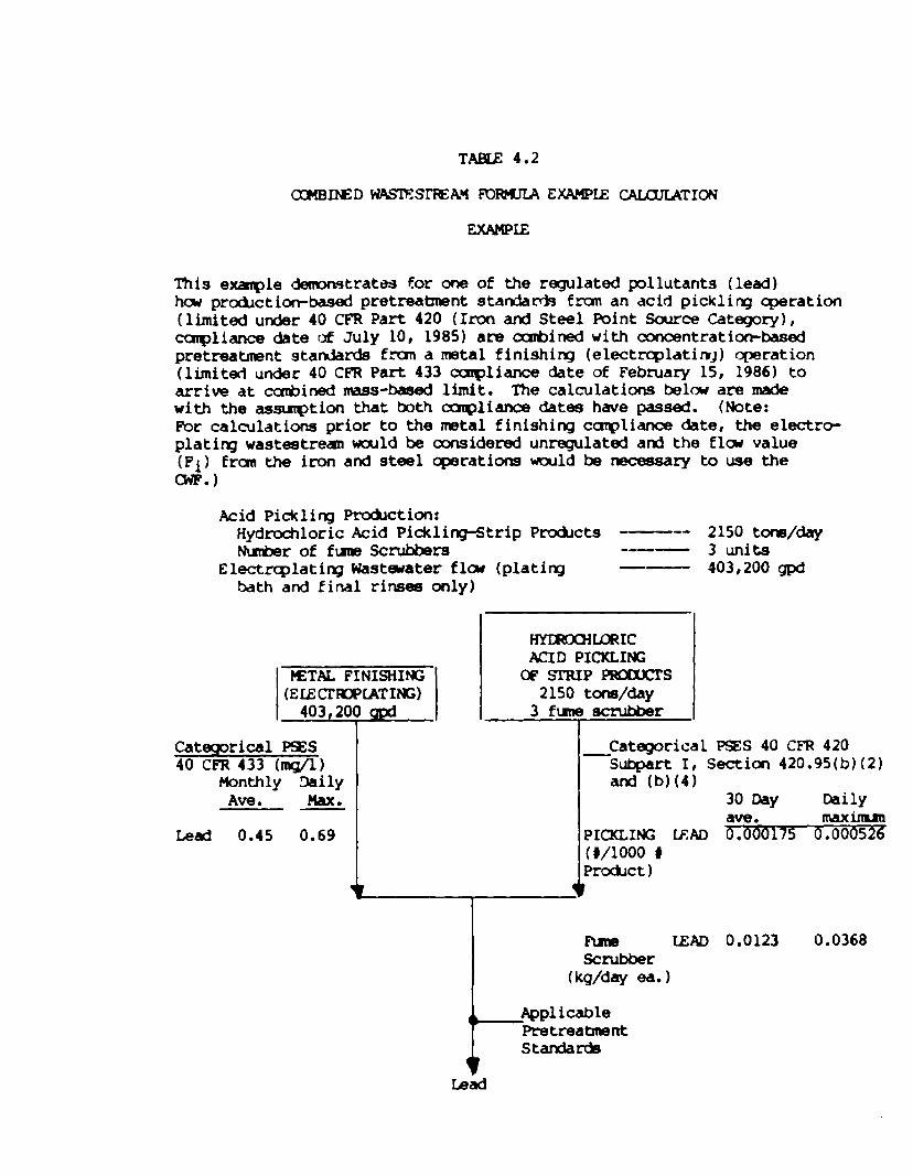
TABLE 4.2
This example demmstrates for one of the regulated pollutants (lead) bar pra&tion-based pretreatment standa& fmn an acid pickling operation (limited under 40 CFR Part 420 (Iron and Steel Point Source Category), carpliance date of July 10, 1985) are canblned with concentratior&ased pretreatmnt Stan&m& from a metal finishirq (electrwlatinl) -ration (limiterl under 40 CFR Part 433 carpliance date of February 15, 1986) to arrive at ccmbined mass-based limit. The calculations belw are made with the assumption that both carpliance dates have passed. (Note: FW calculations prior to the metal finishing canpliance date, the electro- plating waste&rem wcxlld be considered unregulated and the flow value (Pi) fran the iron and steel operations would be necessary to use the CWF.,
Acid Pickling Production: Hydrochloric Acid Pickling-Strip Pmkts --- NunberoffumScrubbem3 s-m
Electrqlating Wastwater flaJ (platirq bath and final rinses only)
lWlROCHLIoRIC ACID PICKLIK;
KU% FINISHII’G (ELECIWPCATfffi)
403,200 c@ I
oFsrRxPPEumlcrS 2150 tons/day
3fmes4xubber I
Cateqorical P%S 40 CFR 433 hg/l)
Monthly Daily Ave. Max.
Lead 0.45 0.69 1
1
2150 tom/day 3 units 403,200 gpd
Categorical PSES 40 CFR 420 -subpart I, Secticm 420.95(b)(2)
and (b)(4) 30 Day Daily ave. llulxirlun
PICKLING; U%D ~.000175 0.000526- 0/1000 # Prcdct) I
lEAD 0.0123 0.0368 scrubber
(kg/day ea. 1

Exmple Calculations
For the Lead Calculation:
Iron and Steel Lead Deily Haxinm Limit - Limit3 for (Pickling) +3(Rme Scubber)
= Categorical Standard for Picklirq x Production Rate for Pickling +3 x (Categorical Standard for each fme scrubber)
= [(0.000526 t/l000 # prabct) x (2150 to&day x 2000 */ton x 1 #/lo00 # product)] + 3 (0.0368 kg/day ea. x 2.2 lb/kg)
Lead (Irm and Steel) - 2.2618 + 0.2429 = 2.50 #/day Daily Max.
Metals Pinishinq Lead hily Maximm Limit - Categorical Standard x flm
- 0.69 nq/l x (403,200 gpd x 8.34/106 Ccmersion Factor)
Lead (,Hetal Finishing) = 2.32 #/day Daily Max.
Since there is m dilution flaJ the applicable pretreabrmt lead daily mximn limit for the facility Is:
Isa Daily ,~imm = 2.50 #/day + 2.32 #/day = 4.82 #/day
The 3O-day limitation, caladatd In a similar manner, fs 2.28 )/day.
4-10

using the CWF, rancher that &en txo or mre regulated wastestreufm are mixed prior to treatmnt, it is necessary to determine which pretreatnrwrt regulation applies to each regulated wastestreun before they are mixed. For additional informaticn on categorical pretreamnt standards and the canbined waste&rem fomula , refer to the manual entitled “CxIidancw Mama1 for the Use of Production-based Pretreatmnt Standards and the Canbfnsd wastes- Pornulae (Septenber 1985). For calculation of the total toxic organic23 (TIO) limit, refer to the rmnual entitled, “Guidance Marual for Inplenenting Total Toxic Organ& (TI’O) Pretreatment Standards (September 1985).
4.5 EEMNAL CFUZDITS
A remval credit allam a FUIW to provide its categorical i&.mtrial users with a credit (in the form of adjusted categorical pretreabmnt standards) for remval of pollutants by the IUTW. Inb3trial users receiving such a credit are allawed to discharge to the POIW greater quantities of regulated pollutants than otherwise permitted by applicable categorical standards. *ether or not to seek authority to grant r-al credits is at the discretion of the PUTW. Section 403.7 of the General Pretreatment Regulations establishes the conditions under uhicfi p FUTW can obtain approval to grant ma1 credits ad specifies the mans by which these removal credit3 am to be determined.
In 1977, Congress anended sectian 307(b) of the Clean Water Act to provide for ranoval credits. EPA originally hplermnted that provision and established the amditions under which KXWs ccruld obtain authorization to grant remval credits in the June 26, 1978, General Pretreatment Regulations. On Jamary 28, 1981, the remval credits pruvisim was agained anended. On Aucpst 3, 1984 (49 Fed. Reg. 31212) the removal credits provisicm was again amnded. UGthe arrent provision, ary ETlIw seeking removal credit authority is required to derrPrrstrate its r-1 perfomnce by saaplirq its influent and effluent and calculating its r-1 rates based on these data. Removal capability of each m, therefore, is to be determined on a -by-case basis. In tiition to the sampling requirements, the provision specified the other prerequisites for obtaining remval credit authority. Only the Approval Authority (either EPA or the State) can grant ranoval credit authority to a RYIW. For rrpre information on removal credits, refer to the meal entitled “c;Uidance Hamal for Preparation and Review of Remsval Credit Applications” (September 1985).
As part of the mmcbmts to the im and steel categorical star&H3 (40 CFR 420.06) EPA acknowledged that biological treatment system arplayed at EUIW’s will, in m measure, rmve those pollutants for which phenols (4A4P) is used as an indicator pollutant to the same degm3 as they remvet phenols (4AAP). Thus, remval allaJames pursuant to 40 CFR 403.7(a)(l) may be granted for phenols (4AAP) limited in the iron and steel incbstzy whether or not it is used as an indicator ot- surrogate pollutant.
4-11

4.6 FUKWENIXLY DIFFERWI’ FAC’mE VARIANCE
A rquest for a fundmmntally different factors (PIP) variance is a me&ani8n by which a categorical pretreatment standard my be adjusted on a caseby-case basis. If an indirect discharger, a KYIW, or any interested pemon believes that the factors relating to a specific indirect discharger are fundmmntally different frm thcee factors amsidemd during development of the relevant catwrical pretreatmnt standard and that the existence of thase factors justifies a different discharge limit frm that specified in the Categorical Standard, then they my suhit a request to EPA for such a variance (See 40 CFR 403.13).
4.7 ulcAL+ LIMITS
Local limits are nxnerical pollutant conmntratim or mass-based values that are develcped by a KJIW for oontmlling the discharge of conventional, nomxmventional, or toxic pollutants fzm indirect saxces. They differ fram national categorical pretmatmnt standards in that catqoriml pretmatmnt standards are c&eloped by EPA and are hsed on the chmmtrated perfonmnce of available pollutant 03ntrol technologies for specific categorical itistries. These technology-based categorical standards Q not comider local enviromental criteria or oamlitions, ht are developed to assure that each itistry within a specified category met8 a minimm dis&arge standard that is consistent for all KJIW acmss the United States. m limits, on the other hand, are developed to address specific localized @acts on FUIW and their reoeiviq waters. Local limits are typically designed to pr&e& the PUIW franr
d Introduction of pollutants into the FUW that could interfere with the -ration
o Pass-thmJgh of inadequately treated pollutants that omld violate a RYXW’s NPIES pennit or applicable water quality standards
o Contuninatim of a RXW’s sludge, which muld limit sluaQe uses or disposal practices.
bcal limits, as the nmne implies, tdce into axmideration the factors that are unique to a FUlW, hemas cateqxical pretreatmnt standa& am develqed only for a general class of inchstrial dischargers. Local limits are required urxler 40 CFR 403.5. For mm infomaticn m the minknm local limit requifemnts for IUIWB with approved pretreabmmt pmgrm3 and the relatiomhip between local limits and categorical standards, refer to the nmmran&m signed by Rebecca liamer cm August 5, 1985 entitled “kxal Limit Rquirmmnts for PllcIIw Pretreatment Program’.
To assist rmmicipalities in devel@q deferrsible and technically sowd ruwrical effluent limits, EPA has prepared general guidelines on limit develqmnt in its doamxmt %&lance Mama1 for FUW Pretmatnmt Prcgraa Develqqmt. ” Appndix L of the nmual lists the general below, required fornulas, and typical envirmnental criteria used to *lap local limits. The wmal is available fran EPA ~egim1 offices and delegated States and should be carefully followed when
4-12

develcpirg local limits. A rrpre detailed guidance mama1 for local limit development is currently under dewlopnent. The general rrretha%logy includes the follaJirg four steps:
step 1 - Determine the maximum headworks loading (for each specific pollutant) that will assure that the objectives of the pretreatment progran are met.
step 2 - Calculate the allowable loading to the PUIW by subtracting the uncontrollable portion of pollutant discharge to the RXW (frun -tic, cannercial, and infiltration/infla sources) fran the total headworks loading value.
step 3 - Distribute the controllable loading to industrial users thrargh an allocation process.
step 4 - Derive specific local limits fran the allocation results.
This four-step process mst be follcwed for each pollutant that the HlIw determines my need a specific local limit. As a general rule, the limit setting analysis sharld be perfo& for all pollutyrts that are discharged to the FQlW in significant quantities. The IUlW can identify pollutants of -rn thmqh its itistrial waste suw. A procedure for evaluating inckstrial waste SULVB~ results is included in the EPA guidance manual mentioned above.
To assist PUIWs with the development of local limits, EPA has also developed a caquter program that incorporates the general methodology required to develm local limits ard perfonm a substantial &r of the calculations required to develop these limits. This cuqx&er program has the follawiq @illties.
0 Performs the four-step limit setting analysis on micmter or mainfrm
0 Screens irgut data provided by the EUIW
o Supplanents FUTW data with built-in files containing data on indrstrfal and rmnicipal wastaJater &aracteristics, KYlW r-al rates and PUlW inhibition values
o Allocates controllable pollutant loads usiq several different ~thod&XJiES
0 Carpares calculated local limits to EPA cateprhl standards.
RYlWs may obtain information on this cuquter prapzfn by contacting the EPA Regiord office. Instructions are available on hew to obtain and use the caquter program as well as how to gain accB99 to a carputer systen that supports it.
4-13

REFERENCES
IRON AND STEEL FEDERAL REGISTER
Final Regulations Promulgated Amended (Effective Date) Amended (Coding and minor errors) Amended (Final and interim regulation) Correction Notice Correction Notice Amended (Final)
GENERAL PRETREATMENT REGULATIONS
40 CFR 403 40 CFR 403 40 CFR 403
05/27/82 47FR 23258 06/07/82 47FR 24554 09/22/82 47FR 41738 10/14/83 48FR 46942 11/10/83 48FR 51647 11/14/83 48FR 51773 04/17/84 49FR 21024
REPORTS AND MANUALS
Final Development Document - Iron and Steel Vol. I-VI May 1982 440/l-82/024
Guidance Manual for POTW Pretreatment Program Development
Procedures Manual for Reviewing a POTW Pretreatment Program Submission
Guidance Manual for Electroplating and Metal Finishing Pretreatment Standards
Guidance Manual for Preparation of Removal Credits Applications
Guidance Manual for Implementing Total Toxic Organics (TTO) Pretreatment Standards
Guidance Manual for the Use of Production-based Pretreatment Standards and the Combined Wastestream Formula
01/28/81 46FR 9404 04/17/84 49FR 21037 (Amended) 08/03/84 49FR 31212
NTIS or GPO Number
PB82-240425 PB82-240433 PB82-240458 PB82-240466 PB82-240474
October 1983
October 1983
February 1984
September 1985
September 1985
September 1985
R-1

Miscellaneous
RCRA Information for Publicly Owned Treatment Works September 1985
Local Limits Requirements for POTW Pretreatment Programs, memorandum signed by Rebecca Hanmer on August 5, 1985.
Copies of the technical and economic documents may be obtained from the National Technical Information Services, Springfield, VA. 22161 (703/487- 4650). Pretreatment Program Manuals may be obtained from U.S. EPA, permits Division (EN-336), Washington, DC 20460.
U.S. GOVERNMENT PRINTING OFFICE 1985 461 217 34935
R-2