guidance for the preparation and quality management of ...nephronurse.co.il/public/iso_23500...
TRANSCRIPT

Reference numberISO 23500:2011(E)
© ISO 2011
INTERNATIONAL STANDARD
ISO23500
First edition2011-05-15
Guidance for the preparation and quality management of fluids for haemodialysis and related therapies
Directives concernant la préparation et le management de la qualité des fluides d'hémodialyse et de thérapies annexes
Licensed to zeitakISO Store order #: 10-1252914/Downloaded: 2012-02-08Single user licence only, copying and networking prohibited
ISO 23500:2011(E)
COPYRIGHT PROTECTED DOCUMENT © ISO 2011 All rights reserved. Unless otherwise specified, no part of this publication may be reproduced or utilized in any form or by any means, electronic or mechanical, including photocopying and microfilm, without permission in writing from either ISO at the address below or ISO's member body in the country of the requester.
ISO copyright office Case postale 56 • CH-1211 Geneva 20 Tel. + 41 22 749 01 11 Fax + 41 22 749 09 47 E-mail [email protected] Web www.iso.org
Published in Switzerland
ii © ISO 2011 – All rights reserved
Licensed to zeitakISO Store order #: 10-1252914/Downloaded: 2012-02-08Single user licence only, copying and networking prohibited
ISO 23500:2011(E)
© ISO 2011 – All rights reserved iii
Contents Page
Foreword .............................................................................................................................................................v Introduction........................................................................................................................................................vi 1 Scope ......................................................................................................................................................1 1.1 General ...................................................................................................................................................1 1.2 Inclusions...............................................................................................................................................1 1.3 Exclusions..............................................................................................................................................1 2 Normative references............................................................................................................................2 3 Terms and definitions ...........................................................................................................................2 4 Summary of quality requirements of ISO 13958, ISO 13959 and ISO 11663 ...................................9 4.1 Dialysis water.........................................................................................................................................9 4.2 Requirements for concentrate ...........................................................................................................11 4.3 Requirements for dialysis fluid..........................................................................................................11 4.4 Record retention..................................................................................................................................12 5 Critical aspects of system design .....................................................................................................13 5.1 Technical aspects................................................................................................................................13 5.2 Microbiological aspects......................................................................................................................13 6 Validation of system performance.....................................................................................................14 6.1 Validation Plan.....................................................................................................................................14 6.2 Installation and Operational Qualification ........................................................................................15 6.3 Performance Qualification..................................................................................................................16 6.4 Routine monitoring and revalidation.................................................................................................16 7 Quality management ...........................................................................................................................17 7.1 General .................................................................................................................................................17 7.2 Monitoring of fluid quality ..................................................................................................................17 7.3 Monitoring of water treatment equipment ........................................................................................18 7.4 Monitoring of water storage and distribution...................................................................................21 7.5 Monitoring of concentrate preparation .............................................................................................22 7.6 Monitoring of concentrate distribution .............................................................................................23 7.7 Monitoring of dialysis fluid proportioning ........................................................................................23 8 Strategies for microbiological control ..............................................................................................23 8.1 General .................................................................................................................................................23 8.2 Disinfection ..........................................................................................................................................24 8.3 Microbiological monitoring methods ................................................................................................26 9 Environment.........................................................................................................................................28 10 Personnel .............................................................................................................................................29 Annex A (informative) Rationale for the development and provisions of this
International Standard ........................................................................................................................30 Annex B (informative) Equipment ...................................................................................................................34 Annex C (informative) Monitoring guidelines for water treatment equipment, distribution systems
and dialysis fluid .................................................................................................................................50 Annex D (informative) Strategies for microbiological control......................................................................55 Annex E (informative) Validation.....................................................................................................................59 Annex F (informative) Special considerations for home haemodialysis ....................................................62
Licensed to zeitakISO Store order #: 10-1252914/Downloaded: 2012-02-08Single user licence only, copying and networking prohibited

ISO 23500:2011(E)
iv © ISO 2011 – All rights reserved
Annex G (informative) Special considerations for acute haemodialysis ....................................................68 Bibliography ......................................................................................................................................................72
Licensed to zeitakISO Store order #: 10-1252914/Downloaded: 2012-02-08Single user licence only, copying and networking prohibited
ISO 23500:2011(E)
© ISO 2011 – All rights reserved v
Foreword
ISO (the International Organization for Standardization) is a worldwide federation of national standards bodies (ISO member bodies). The work of preparing International Standards is normally carried out through ISO technical committees. Each member body interested in a subject for which a technical committee has been established has the right to be represented on that committee. International organizations, governmental and non-governmental, in liaison with ISO, also take part in the work. ISO collaborates closely with the International Electrotechnical Commission (IEC) on all matters of electrotechnical standardization.
International Standards are drafted in accordance with the rules given in the ISO/IEC Directives, Part 2.
The main task of technical committees is to prepare International Standards. Draft International Standards adopted by the technical committees are circulated to the member bodies for voting. Publication as an International Standard requires approval by at least 75 % of the member bodies casting a vote.
Attention is drawn to the possibility that some of the elements of this document may be the subject of patent rights. ISO shall not be held responsible for identifying any or all such patent rights.
ISO 23500 was prepared by Technical Committee ISO/TC 150, Implants for surgery, Subcommittee SC 2, Cardiovascular implants and extracorporeal systems.
Licensed to zeitakISO Store order #: 10-1252914/Downloaded: 2012-02-08Single user licence only, copying and networking prohibited

ISO 23500:2011(E)
vi © ISO 2011 – All rights reserved
Introduction
This International Standard was developed by Working Group 5 of ISO/TC 150/SC 2. The Working Group's objective was to provide users with guidance for handling water and concentrates and for the production and monitoring of dialysis fluid used for haemodialysis. The need for such guidance is based on the critical role of dialysis fluid quality in providing safe and effective haemodialysis, and the recognition that day-to-day dialysis fluid quality is under the control of the healthcare professionals who deliver dialysis therapy.
Quality requirements for the water and concentrates used to prepare dialysis fluid, and for that dialysis fluid, are provided in ISO 13959, ISO 13958 and ISO 11663, respectively. This International Standard does not address clinical issues that might be associated with inappropriate usage of the water, concentrates or final dialysis fluid. Healthcare professionals involved in the provision of treatment for kidney failure should make the final decision regarding the applications with which these fluids are used, for example, haemodialysis, haemodiafiltration, high-flux haemodialysis, and the reprocessing of dialysers, and need to be aware of the issues that the use of inappropriate fluid quality raises in each of the therapies.
The equipment used in the various stages of dialysis fluid preparation is generally obtained from specialized vendors. Dialysis practitioners are generally responsible for maintaining that equipment following its installation. Therefore, this International Standard provides guidance on monitoring and maintenance of the equipment to ensure that dialysis fluid quality is acceptable at all times. At various places throughout this International Standard, the user is advised to follow the manufacturer's instructions regarding the operation and maintenance of equipment. In those instances in which the equipment is not obtained from a specialized vendor, it is the responsibility of the user to validate the performance of the equipment in the haemodialysis setting and to ensure that appropriate operating and maintenance manuals are available. Annex B provides a general description of the system components that are used for water treatment and concentrate preparation at a dialysis facility. These descriptions are intended to provide the user with a basis for understanding why certain equipment might be required and how it should be configured; they are not intended as detailed design standards. Requirements for water treatment equipment are provided in ISO 26722.
The verbal forms used in this International Standard conform to usage described in Annex H of the ISO/IEC Directives, Part 2:2004. For the purposes of this standard, the auxiliary verb:
⎯ “shall” means that compliance with a requirement or a test is mandatory for compliance with this standard;
⎯ “should” means that compliance with a requirement or a test is recommended but is not mandatory for compliance with this standard;
⎯ “may” is used to describe a permissible way to achieve compliance with a requirement or test.
This International Standard reflects the conscientious efforts of healthcare professionals, patients, and medical device manufacturers to develop recommendations for handling water and concentrates, and for the production and monitoring of dialysis fluid for haemodialysis. This International Standard is directed towards the healthcare professionals involved in the management of haemodialysis patients and healthcare professionals involved in the routine care of haemodialysis patients. The recommendations contained in this International Standard might not be applicable in all circumstances and they are not intended for regulatory application.
The guidance provided by this International Standard should help protect haemodialysis patients from adverse effects arising from known chemical and microbial contaminants that might be found in improperly prepared dialysis fluid. However, the physician in charge of dialysis has the ultimate responsibility for ensuring that the dialysis fluid is correctly formulated and meets the requirements of all applicable quality standards.
The concepts incorporated in this International Standard should not be considered inflexible or static. The recommendations presented here should be reviewed periodically in order to assimilate increased understanding of the role of dialysis fluid purity in patient outcomes and technological developments.
Licensed to zeitakISO Store order #: 10-1252914/Downloaded: 2012-02-08Single user licence only, copying and networking prohibited
INTERNATIONAL STANDARD ISO 23500:2011(E)
© ISO 2011 – All rights reserved 1
Guidance for the preparation and quality management of fluids for haemodialysis and related therapies
1 Scope
1.1 General
This International Standard provides dialysis practitioners with guidance on the preparation of dialysis fluid for haemodialysis and related therapies and substitution fluid for use in online therapies, such as haemodiafiltration and haemofiltration. As such, this International Standard functions as a recommended practice.
1.2 Inclusions
This International Standard addresses the user's responsibility for the dialysis fluid once the equipment used in its preparation has been delivered and installed. For the purposes of this International Standard, the dialysis fluid includes water used for the preparation of dialysis fluid and substitution fluid, water used for the preparation of concentrates at the user's facility, as well as concentrates and the final dialysis fluid and substitution fluid.
Included in the scope of this International Standard are
a) the quality management of equipment used to treat and distribute water used for the preparation of dialysis fluid and substitution fluid, from the point at which municipal water enters the dialysis facility to the point at which the final dialysis fluid enters the dialyser or the point at which substitution fluid is infused,
b) equipment used to prepare concentrate from powder or other highly concentrated media at a dialysis facility, and
c) preparation of the final dialysis fluid or substitution fluid from dialysis water and concentrates.
NOTE Because water used to prepare dialysis fluid is commonly prepared and distributed using the same equipment as the water used to reprocess dialysers, water used to reprocess dialysers is also covered by this International Standard.
1.3 Exclusions
Excluded from the scope of this International Standard are sorbent-based dialysis fluid regeneration systems that regenerate and recirculate small volumes of dialysis fluid, systems for continuous renal replacement therapy that use prepackaged solutions, and systems and solutions for peritoneal dialysis.
Licensed to zeitakISO Store order #: 10-1252914/Downloaded: 2012-02-08Single user licence only, copying and networking prohibited
ISO 23500:2011(E)
2 © ISO 2011 – All rights reserved
2 Normative references
The following referenced documents are indispensable for the application of this document. For dated references, only the edition cited applies. For undated references, the latest edition of the referenced document (including any amendments) applies.
ISO 13958:2009, Concentrates for haemodialysis and related therapies
ISO 13959:2009, Water for haemodialysis and related therapies
ISO 11663:2009, Quality of dialysis fluid for haemodialysis and related therapies
ISO 26722:2009, Water treatment equipment for haemodialysis applications and related therapies
3 Terms and definitions
For the purposes of this document, the following terms and definitions apply.
3.1 acetate concentrate concentrated solution of salts containing acetate, which, when diluted with dialysis water, yields bicarbonate-free dialysis fluid for use in dialysis
NOTE 1 Acetate concentrate may contain glucose.
NOTE 2 Acetate is used to provide buffer in place of sodium bicarbonate.
NOTE 3 Acetate concentrate is used as a single concentrate.
3.2 acid concentrate A-concentrate acidified concentrated mixture of salts which, when diluted with dialysis water and bicarbonate concentrate, yields dialysis fluid for use in dialysis
NOTE 1 The term “acid” refers to the small amount of acid (usually acetic acid) that is included in the concentrate.
NOTE 2 Acid concentrate may contain glucose.
NOTE 3 Acid concentrate may be in the form of a liquid, a dry powder, other highly concentrated media, or some combination of these forms.
3.3 action level concentration of a contaminant at which steps should be taken to interrupt the trend toward higher, unacceptable levels
3.4 additive spike small amount of a single chemical that, when added to the concentrate, will increase the concentration of a single existing chemical by a value labelled on the additive packaging
Licensed to zeitakISO Store order #: 10-1252914/Downloaded: 2012-02-08Single user licence only, copying and networking prohibited
ISO 23500:2011(E)
© ISO 2011 – All rights reserved 3
3.5 bicarbonate concentrate B-concentrate concentrated preparation of sodium bicarbonate that, when diluted with dialysis water and acid concentrate, makes dialysis fluid used for dialysis
NOTE 1 Sodium bicarbonate is also known as sodium hydrogen carbonate.
NOTE 2 Some bicarbonate concentrates also contain sodium chloride.
NOTE 3 Bicarbonate concentrate may be in the form of a liquid or a dry powder.
NOTE 4 Dry sodium bicarbonate, without added sodium chloride, is also used in concentrate generators to produce a concentrated solution of sodium bicarbonate used by the dialysis machine to make dialysis fluid.
3.6 biofilm microbially-derived sessile community characterized by cells that are irreversibly attached to a substratum or interface or to each other, are imbedded in a matrix of extracellular polymeric substances that they have produced, and exhibit an altered phenotype with respect to growth rate and gene transcription
NOTE 1 The matrix, a slimy material secreted by the cells, protects the bacteria from antibiotics and chemical disinfectants.
NOTE 2 A certain amount of biofilm formation is considered unavoidable in dialysis water systems. When the level of biofilm is such that the action levels for microorganisms and endotoxins in the dialysis water cannot be routinely achieved, the operation of the system is compromised from a medical and technical point of view. This level of biofilm formation is often referred to as biofouling.
3.7 bleach solution of sodium hypochlorite normally used for household cleaning and disinfection
3.8 bulk delivery delivery of large volume containers of concentrate to a dialysis facility
NOTE Bulk delivery includes containers such as drums, which can be pumped into a storage tank maintained at the user's facility. Alternatively, the drums can be left at the facility and used to fill transfer containers to transfer the concentrate to the dialysis machines. Bulk delivery can also include large containers for direct connection to a central concentrate supply system.
3.9 central concentrate system system that prepares and/or stores concentrate at a central point for subsequent distribution to its points of use
3.10 central dialysis fluid delivery system system that produces dialysis fluid from dialysis water and concentrate or powder at a central point and distributes the dialysis fluid from the central point to individual dialysis machines
3.11 chlorine, combined chlorine that is chemically combined, such as in chloramine compounds
NOTE There is no direct test for measuring combined chlorine, but it can be measured indirectly by measuring both total and free chlorine and calculating the difference.
Licensed to zeitakISO Store order #: 10-1252914/Downloaded: 2012-02-08Single user licence only, copying and networking prohibited

ISO 23500:2011(E)
4 © ISO 2011 – All rights reserved
3.12 chlorine, free chlorine present in water as dissolved molecular chlorine (Cl2), hypochlorous acid (HOCl) and hypochlorite ion (OCl−)
NOTE The three forms of free chlorine exist in equilibrium.
3.13 chlorine, total sum of free and combined chlorine
NOTE Chlorine can exist in water as dissolved molecular chlorine, hypochlorous acid and/or hypochlorite ion (free chlorine) or in chemically combined forms (combined chlorine). Where chloramine is used to disinfect water supplies, chloramine is usually the principal component of combined chlorine.
3.14 colony-forming unit CFU measure of bacterial or fungal cell numbers that theoretically arise from a single cell when grown on solid media
NOTE Colonies can also form from groups of organisms when they occur in aggregates.
3.15 concentrate generator system where the concentrate is delivered to the user as a powder in a container, suitable for attachment to the dialysis machine with which it is intended to be used, and then the powder is converted into a concentrated solution by the dialysis machine
NOTE The solution produced by the concentrate generator is used by the dialysis machine to make the final dialysis fluid delivered to the dialyser.
3.16 dialysis fluid dialysate dialysis solution aqueous fluid containing electrolytes and, usually, buffer and glucose, which is intended to exchange solutes with blood during haemodialysis
NOTE 1 The term “dialysis fluid” is used throughout this International Standard to mean the fluid made from dialysis water and concentrates that is delivered to the dialyser by the dialysis fluid delivery system. Such phrases as “dialysate” or “dialysis solution” may be used in place of dialysis fluid.
NOTE 2 The dialysis fluid entering the dialyser is referred to as “fresh dialysis fluid”, while the fluid leaving the dialyser is referred to as “spent dialysis fluid”.
NOTE 3 Dialysis fluid does not include prepackaged parenteral fluids used in some renal replacement therapies, such as haemodiafiltration and haemofiltration.
Licensed to zeitakISO Store order #: 10-1252914/Downloaded: 2012-02-08Single user licence only, copying and networking prohibited
ISO 23500:2011(E)
© ISO 2011 – All rights reserved 5
3.17 dialysis fluid delivery system device that: prepares dialysis fluid online from dialysis water and concentrates or that stores and distributes premixed dialysis fluid; circulates the dialysis fluid through the dialyser; monitors the dialysis fluid for temperature, conductivity (or equivalent), pressure, flow, and blood leaks; and prevents dialysis during disinfection or cleaning modes
NOTE 1 The term includes reservoirs, conduits, proportioning devices for the dialysis fluid, and monitors and associated alarms and controls assembled as a system for the purposes listed above.
NOTE 2 The dialysis fluid delivery system may be an integral part of the single-patient dialysis machine or a centralized preparation system which feeds multiple bedside monitoring systems.
NOTE 3 Dialysis fluid delivery systems are also known as proportioning systems and dialysis fluid supply systems.
3.18 dialysis water water that has been treated to meet the requirements of ISO 13959 and which is suitable for use in haemodialysis applications, including the preparation of dialysis fluid, reprocessing of dialysers, preparation of concentrates and preparation of substitution fluid for online convective therapies
3.19 disinfection destruction of pathogenic and other kinds of microorganisms by thermal or chemical means
NOTE Disinfection is a less lethal process than sterilization, because it destroys most recognized pathogenic microorganisms but does not necessarily destroy all microbial forms.
3.20 empty-bed contact time EBCT time taken by a fluid to pass through an empty volume equal to the volume of a particle bed
NOTE 1 EBCT (min) is calculated from the following equation:
EBCT = V/Q
where
V is the volume of the particle bed, in cubic metres (m3);
Q is the flow rate of water through the bed, in cubic metres per minute (m3/min).
NOTE 2 EBCT is used as an indirect measure of how much contact occurs between particles, such as activated carbon, and water as the water flows through a bed of particles.
3.21 endotoxin major component of the outer cell wall of gram-negative bacteria
NOTE Endotoxins are lipopolysaccharides, which consist of a polysaccharide chain covalently bound to lipid A. Endotoxins can acutely activate both humoral and cellular host defences, leading to a syndrome characterized by fever, shaking, chills, hypotension, multiple organ failure, and even death if allowed to enter the circulation in a sufficient dose [see also pyrogen (3.37)].
Licensed to zeitakISO Store order #: 10-1252914/Downloaded: 2012-02-08Single user licence only, copying and networking prohibited
ISO 23500:2011(E)
6 © ISO 2011 – All rights reserved
3.22 endotoxin-retentive filter ETRF membrane filter used to remove endotoxins and microorganisms from dialysis water or dialysis fluid
NOTE 1 The performance of an endotoxin-retentive filter is usually expressed as the logarithmic reduction value (LRV), defined as log10(inlet concentration)/(outlet concentration).
NOTE 2 Endotoxin-retentive filters may be configured in a cross-flow or dead-end mode. Some endotoxin-retentive filters also remove endotoxins by adsorption.
3.23 endotoxin units EU units assayed by the Limulus amoebocyte lysate (LAL) test when testing for endotoxins
NOTE 1 Because activity of endotoxins depends on the bacteria from which they are derived, their activity is referred to a standard endotoxin.
NOTE 2 In some countries, endotoxin concentrations are expressed in international units (IU). Since the harmonization of endotoxin assays, EU and IU are equivalent.
3.24 feed water water supplied to a water treatment system or an individual component of a water treatment system
3.25 germicide agent that kills microorganisms
3.26 haemodiafiltration form of renal replacement therapy in which waste solutes are removed from blood by a combination of diffusion and convection through a high-flux membrane
NOTE Diffusive solute removal is achieved using a dialysis fluid stream as in haemodialysis. Convective solute removal is achieved by adding ultrafiltration in excess of that needed to obtain the desired weight loss; fluid balance is maintained by infusing a replacement solution into the blood either before the dialyser (predilution haemodiafiltration), after the dialyser (postdilution haemodiafiltration), or a combination of the two (mixed dilution haemodiafiltration).
3.27 haemodialysis form of renal replacement therapy in which waste solutes are removed primarily by diffusion from blood flowing on one side of a membrane into dialysis fluid flowing on the other side
NOTE Fluid removal that is sufficient to obtain the desired weight loss is achieved by establishing a hydrostatic pressure gradient across the membrane. This fluid removal provides some additional waste solute removal, particularly for solutes with higher molecular weight.
3.28 haemofiltration form of renal replacement therapy in which waste solutes are removed from blood by convection
NOTE 1 Convective transport is achieved by ultrafiltration through a high-flux membrane. Fluid balance is maintained by infusing a replacement solution into the blood either before the haemofilter (predilution haemofiltration), after the haemofilter (post-dilution haemofiltration), or a combination of the two (mixed dilution haemofiltration).
NOTE 2 There is no dialysis fluid stream in haemofiltration.
Licensed to zeitakISO Store order #: 10-1252914/Downloaded: 2012-02-08Single user licence only, copying and networking prohibited
ISO 23500:2011(E)
© ISO 2011 – All rights reserved 7
3.29 heterotrophic not self-sustaining, i.e. a type of nutrition in which organisms derive energy from the oxidation of organic compounds by either consumption or absorption of other organisms
3.30 Limulus amoebocyte lysate test LAL test assay used to detect endotoxin
NOTE The detection method uses the chemical response of an extract from blood cells of the horseshoe crab (Limulus polyphemus) to endotoxins.
3.31 manufacturer entity that designs, manufactures, fabricates, assembles or processes a finished device
NOTE Manufacturers include, but are not limited to, those who perform the functions of contract sterilization, installation, relabelling, remanufacturing, repacking, or specification development, and initial distributions of foreign entities performing these functions. The term does not cover preparation of concentrates from prepackaged dry chemicals at a dialysis facility or the handling of bulk concentrates at a dialysis facility after responsibility for the concentrate is transferred from the manufacturer to the user.
3.32 microbiological contamination contamination with any form of microorganism (e.g. bacteria, yeast, fungi and algae) or with the by-products of living or dead organisms, such as endotoxins, exotoxins and cyanobacterial toxins (derived from blue-green algae)
3.33 microfilter filter designed to remove particles larger than 0,1 µm in size
NOTE Microfilters have an absolute size cut-off and are available in both dead-end and cross-flow configurations. Some microfilters can reduce the concentration of endotoxins by a process of adsorption.
3.34 nonpyrogenic having less than 0,03 EU/ml
NOTE Historically, the threshold pyrogenic dose of 5 EU/kg/h (the minimum dose that produces fever) has been used to set endotoxin limits of devices and injectable medications.
3.35 product water water produced by a water treatment system or by an individual device thereof
3.36 proportioning system apparatus that proportions dialysis water and haemodialysis concentrate to prepare dialysis fluid
3.37 pyrogen fever-producing substance
NOTE Pyrogens are most often lipopolysaccharides of gram-negative bacterial origin (see also endotoxin).
Licensed to zeitakISO Store order #: 10-1252914/Downloaded: 2012-02-08Single user licence only, copying and networking prohibited
ISO 23500:2011(E)
8 © ISO 2011 – All rights reserved
3.38 sterile free from viable microorganisms
NOTE 1 “Sterile” can be used to describe a packaged solution that was prepared using a terminal sterilization process validated according to the methods of the applicable pharmacopoeia. A terminal sterilization process is commonly defined as one that achieves a sterility assurance level (SAL) of 10−6, i.e. assurance of less than one chance in a million that viable microorganisms are present in the sterilized article.
NOTE 2 Alternatively, “sterile” can be used to describe a solution prepared for immediate use by a continuous process, such as filtration, that has been validated according to the methods of the applicable pharmacopoeia to produce a solution free of microorganisms for the validated life of the filter.
3.39 storage tank tank at the user's facility for storage of dialysis water or concentrate from bulk deliveries, or for concentrate prepared in bulk at the user's facility from powder and dialysis water
3.40 substitution fluid fluid used in haemofiltration and haemodiafiltration treatments which is infused directly into the patient's blood as a replacement for the fluid that is removed from the blood by filtration
NOTE 1 Substitution fluid is also referred to as substitution solution or replacement solution.
NOTE 2 Substitution fluid may also be used for bolus administration, for priming of an extracorporeal blood circuit and for returning blood to the patient at the end of a treatment.
3.41 total dissolved solids TDS sum of all ions in a solution, often approximated by means of electrical conductivity or resistivity measurements
NOTE TDS measurements are commonly used to assess the performance of reverse osmosis units. TDS values are often expressed in terms of CaCO3, NaCl, KCl, or 442 equivalents, in milligrams per litre (mg/l). [442 is a solution of sodium sulfate (40 %), sodium bicarbonate (40 %), and sodium chloride (20 %) that closely represents the conductivity to concentration relationship, on average, for naturally occurring fresh water.]
3.42 ultrapure dialysis fluid highly purified dialysis fluid that can be used in place of conventional dialysis fluid
NOTE A widely accepted specification of ultrapure dialysis fluid is <0,1 CFU/ml and <0,03 EU/ml.
3.43 user physician or physician's representative responsible for the actual production and handling of dialysis fluid
NOTE This International Standard is directed to the “user”.
Licensed to zeitakISO Store order #: 10-1252914/Downloaded: 2012-02-08Single user licence only, copying and networking prohibited

ISO 23500:2011(E)
© ISO 2011 – All rights reserved 9
3.44 validation process of documenting that the water treatment and dialysis fluid production systems, when installed and operated according to the manufacturer's recommendations, consistently produce water or dialysis fluid meeting the stipulated quality levels
NOTE 1 In this context, validation also includes demonstrating that the system is “fit for purpose”.
NOTE 2 The term “verification” is also used and refers to demonstrating that the system complies with applicable regulations, specifications, or other conditions. A dialysis facility might be interested in both validation and verification of its fluid production systems.
3.45 water treatment system collection of water treatment devices and associated piping, pumps, valves, gauges, etc., that together produce water for dialysis meeting the requirements of ISO 13959 for haemodialysis applications and deliver it to the point of use
4 Summary of quality requirements of ISO 13958, ISO 13959 and ISO 11663
The quality requirements set forth in this clause are reproduced from the 2009 editions of ISO 13958, ISO 13959 and ISO 11663. The latest editions of these International Standards should be consulted to ascertain if there have been any changes to those requirements before implementing the recommendations of this International Standard.
4.1 Dialysis water
4.1.1 General
The requirements contained in this clause apply to dialysis water at its point of use. As such, these requirements apply to the water treatment system as a whole and not to each of the devices that make up the system. However, collectively, the individual devices shall produce water that, at a minimum, meets the requirements of this clause.
4.1.2 Chemical contaminants in dialysis water
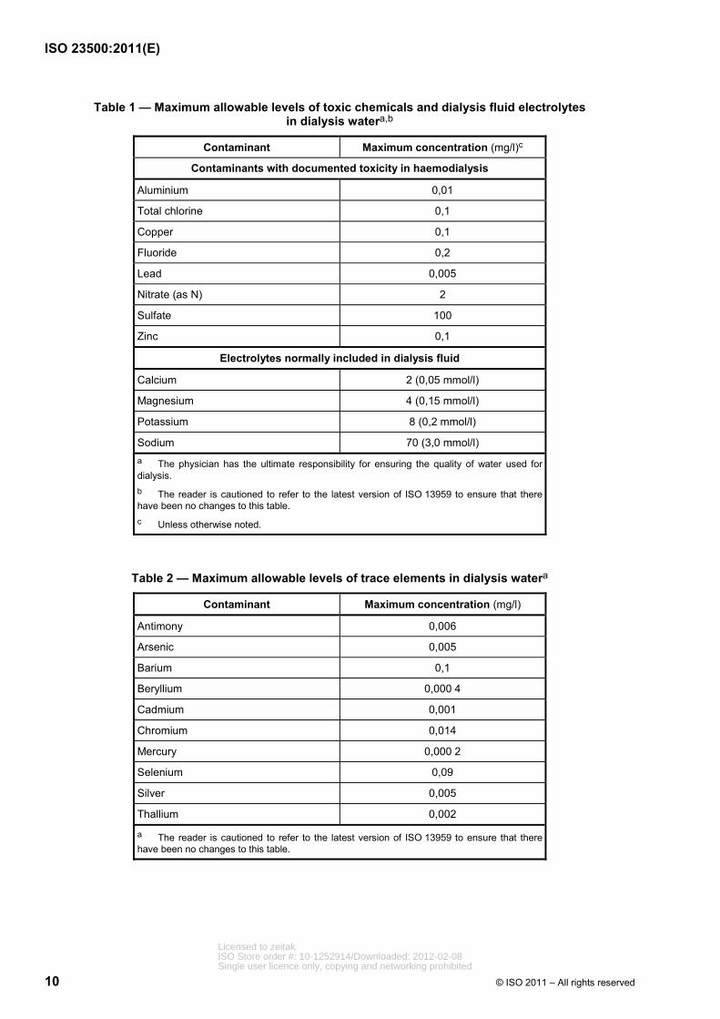
Dialysis water shall not contain substances at levels greater than those listed in ISO 13959 (see Tables 1 and 2). The manufacturer or supplier of a complete water treatment system should recommend a system that is capable of meeting these requirements based on a feed-water analysis. The system design should reflect possible seasonal variations in feed-water quality. The manufacturer or supplier of a complete water treatment and distribution system should demonstrate that the complete water treatment, storage and distribution system is capable of meeting the requirements of ISO 13959 at the time of installation.
Following installation of a water treatment, storage and distribution system, the user is responsible for regular monitoring of the levels of chemical contaminants in the water and for complying with the requirements of this International Standard.
Tables 1 and 2 are reproduced from ISO 13959:2009.
Licensed to zeitakISO Store order #: 10-1252914/Downloaded: 2012-02-08Single user licence only, copying and networking prohibited
ISO 23500:2011(E)
10 © ISO 2011 – All rights reserved
Table 1 — Maximum allowable levels of toxic chemicals and dialysis fluid electrolytes in dialysis watera,b
Contaminant Maximum concentration (mg/l)c
Contaminants with documented toxicity in haemodialysis
Aluminium 0,01
Total chlorine 0,1
Copper 0,1
Fluoride 0,2
Lead 0,005
Nitrate (as N) 2
Sulfate 100
Zinc 0,1
Electrolytes normally included in dialysis fluid
Calcium 2 (0,05 mmol/l)
Magnesium 4 (0,15 mmol/l)
Potassium 8 (0,2 mmol/l)
Sodium 70 (3,0 mmol/l) a The physician has the ultimate responsibility for ensuring the quality of water used for dialysis. b The reader is cautioned to refer to the latest version of ISO 13959 to ensure that there have been no changes to this table. c Unless otherwise noted.
Table 2 — Maximum allowable levels of trace elements in dialysis watera
Contaminant Maximum concentration (mg/l)
Antimony 0,006
Arsenic 0,005
Barium 0,1
Beryllium 0,000 4
Cadmium 0,001
Chromium 0,014
Mercury 0,000 2
Selenium 0,09
Silver 0,005
Thallium 0,002
a The reader is cautioned to refer to the latest version of ISO 13959 to ensure that there have been no changes to this table.
Licensed to zeitakISO Store order #: 10-1252914/Downloaded: 2012-02-08Single user licence only, copying and networking prohibited

ISO 23500:2011(E)
© ISO 2011 – All rights reserved 11
4.1.3 Microbiological contaminants in dialysis water
The total viable microbial count and endotoxin concentration in dialysis water shall comply with the maximum allowable levels specified in ISO 13959 (see Table 3). Action levels for the total viable microbial count and endotoxin concentration shall also be set, based on knowledge of the microbial dynamics of the system. Typically, the action level is set at 50 % of the maximum allowable level for bacteria and endotoxins. If a total viable microbial count or endotoxin concentration at or above the action level is observed in the dialysis water, corrective measures should be taken promptly to reduce the level. The manufacturer or supplier of a complete water treatment and distribution system should demonstrate that the complete water treatment, storage, and distribution system is capable of meeting the requirements of ISO 13959 at the time of installation.
Following installation of a water treatment, storage and distribution system, the user is responsible for regular monitoring of the water microbiology of the system and for complying with the requirements of this International Standard, including those requirements related to action levels.
Table 3 is adapted from ISO 13959:2009.
Table 3 — Maximum allowable levels for total viable microbial count (TVC) and endotoxins in dialysis watera
Contaminant Maximum allowable level Action levelb
TVC <100 CFU/ml 50 CFU/ml
Endotoxin <0,25 EU/ml 0,125 EU/ml a The reader is cautioned to refer to the latest version of ISO 13959 to ensure that there have been no changes to the values presented in this table. b Typically set at 50 % of the maximum allowable level. Lower values may be set.
4.2 Requirements for concentrate
4.2.1 Chemical and microbiological contaminants in concentrate
Concentrates used to prepare dialysis fluid shall comply with the quality requirements specified in ISO 13958.
Bicarbonate concentrate can grow bacteria and caution should be used to limit the bacterial levels in bicarbonate concentrate.
4.2.2 Water used to prepare concentrate
Water used to prepare concentrates at a dialysis facility shall meet the requirements of ISO 13959. Any concentrate prepared at a dialysis facility shall permit the dialysis machine to prepare dialysis fluid meeting the requirements of ISO 11663.
4.3 Requirements for dialysis fluid
4.3.1 General
The requirements contained in this clause apply to a sample of the dialysis fluid collected as close as practicable to the inlet to the dialyser.
ISO 11663 defines three levels of dialysis fluid: standard dialysis fluid; ultrapure dialysis fluid; and online-prepared substitution fluid. Standard dialysis fluid is considered the minimum acceptable quality for routine haemodialysis. Ultrapure dialysis fluid is recommended for routine haemodialysis.
Licensed to zeitakISO Store order #: 10-1252914/Downloaded: 2012-02-08Single user licence only, copying and networking prohibited
ISO 23500:2011(E)
12 © ISO 2011 – All rights reserved
4.3.2 Microbiological contaminants in standard dialysis fluid
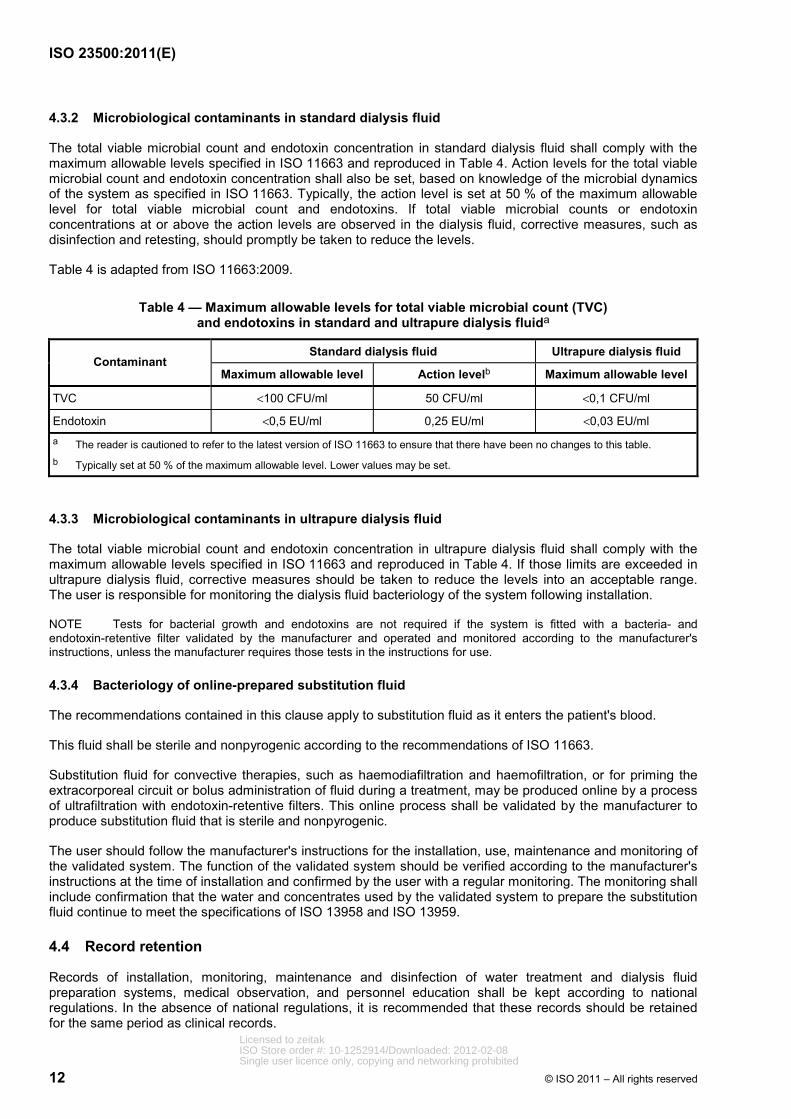
The total viable microbial count and endotoxin concentration in standard dialysis fluid shall comply with the maximum allowable levels specified in ISO 11663 and reproduced in Table 4. Action levels for the total viable microbial count and endotoxin concentration shall also be set, based on knowledge of the microbial dynamics of the system as specified in ISO 11663. Typically, the action level is set at 50 % of the maximum allowable level for total viable microbial count and endotoxins. If total viable microbial counts or endotoxin concentrations at or above the action levels are observed in the dialysis fluid, corrective measures, such as disinfection and retesting, should promptly be taken to reduce the levels.
Table 4 is adapted from ISO 11663:2009.
Table 4 — Maximum allowable levels for total viable microbial count (TVC) and endotoxins in standard and ultrapure dialysis fluida
Standard dialysis fluid Ultrapure dialysis fluid Contaminant
Maximum allowable level Action levelb Maximum allowable level
TVC <100 CFU/ml 50 CFU/ml <0,1 CFU/ml
Endotoxin <0,5 EU/ml 0,25 EU/ml <0,03 EU/ml a The reader is cautioned to refer to the latest version of ISO 11663 to ensure that there have been no changes to this table. b Typically set at 50 % of the maximum allowable level. Lower values may be set.
4.3.3 Microbiological contaminants in ultrapure dialysis fluid
The total viable microbial count and endotoxin concentration in ultrapure dialysis fluid shall comply with the maximum allowable levels specified in ISO 11663 and reproduced in Table 4. If those limits are exceeded in ultrapure dialysis fluid, corrective measures should be taken to reduce the levels into an acceptable range. The user is responsible for monitoring the dialysis fluid bacteriology of the system following installation.
NOTE Tests for bacterial growth and endotoxins are not required if the system is fitted with a bacteria- and endotoxin-retentive filter validated by the manufacturer and operated and monitored according to the manufacturer's instructions, unless the manufacturer requires those tests in the instructions for use.
4.3.4 Bacteriology of online-prepared substitution fluid
The recommendations contained in this clause apply to substitution fluid as it enters the patient's blood.
This fluid shall be sterile and nonpyrogenic according to the recommendations of ISO 11663.
Substitution fluid for convective therapies, such as haemodiafiltration and haemofiltration, or for priming the extracorporeal circuit or bolus administration of fluid during a treatment, may be produced online by a process of ultrafiltration with endotoxin-retentive filters. This online process shall be validated by the manufacturer to produce substitution fluid that is sterile and nonpyrogenic.
The user should follow the manufacturer's instructions for the installation, use, maintenance and monitoring of the validated system. The function of the validated system should be verified according to the manufacturer's instructions at the time of installation and confirmed by the user with a regular monitoring. The monitoring shall include confirmation that the water and concentrates used by the validated system to prepare the substitution fluid continue to meet the specifications of ISO 13958 and ISO 13959.
4.4 Record retention
Records of installation, monitoring, maintenance and disinfection of water treatment and dialysis fluid preparation systems, medical observation, and personnel education shall be kept according to national regulations. In the absence of national regulations, it is recommended that these records should be retained for the same period as clinical records.
Licensed to zeitakISO Store order #: 10-1252914/Downloaded: 2012-02-08Single user licence only, copying and networking prohibited
ISO 23500:2011(E)
© ISO 2011 – All rights reserved 13
5 Critical aspects of system design
The preparation of dialysis fluid, from inlet municipal water and acquisition of concentrates to discharge of spent dialysis fluid into the drain system, involves numerous components that, together, form a dialysis fluid handling system. The technical features of the water treatment component of that system should be based on the criteria listed in ISO 26722, with special regard to the aspects related to the water quality, the optimal use of resources (e.g. water and energy) and the operations of disinfection and maintenance. Concentrates may be obtained from a supplier in a ready-to-use form or prepared at the dialysis facility from dialysis water and prepackaged salts. The technical features of the concentrate preparation and distribution component of the system should be based on the criteria listed in ISO 13958.
5.1 Technical aspects
In accordance with the requirements listed in ISO 26722, the system design should specifically address the following points:
⎯ compliance with mandatory local regulations;
⎯ capability to operate with the available feed-water supply and over the anticipated range of variation in the quality of that water, to include both variations arising from changes in the quality of the source water used by the provider of the feed water and variations introduced by the provider in treating that water;
NOTE Source water is assumed to be potable water.
⎯ provision for adequate process monitoring;
⎯ service and maintenance.
If the entire fluid handling system is not obtained from a single supplier, then the user becomes responsible for ensuring that the separate parts of the system are compatible. For example, it is important that the pretreatment section of the water treatment system be designed to supply the main purification device (usually reverse osmosis) with feed water meeting the specifications for that device; i.e. pressure, temperature, flow and quality (for example, elimination of chemicals which cannot be effectively removed by the main purification device or that could damage it).
The choice of the water treatment system should consider the following aspects concerning the feed-water supply:
⎯ full chemical analysis of the feed water and silt density index (SDI);
⎯ microbiological load, which could lead to the introduction of an additional chlorination step;
⎯ flow rates, pressure and temperature;
⎯ the treatment techniques used by the provider of the feed water (for example, addition of chloramine, fluoride, aluminium sulfate, etc.). Because treatment techniques can change, ongoing communication with the provider of the feed water is recommended.
5.2 Microbiological aspects
The required microbiological quality of the dialysis water and dialysis fluid is achieved by paying adequate attention to the entire water treatment and dialysis fluid preparation cascade. For this reason, the system should be designed to reduce, as much as possible, potential sources of contamination and to allow effective monitoring and disinfection of the critical parts.
When applicable, equipment should be operated on a regular basis to reduce stagnation.
Licensed to zeitakISO Store order #: 10-1252914/Downloaded: 2012-02-08Single user licence only, copying and networking prohibited

ISO 23500:2011(E)
14 © ISO 2011 – All rights reserved
The distribution system should be designed to maintain dialysis water or dialysis fluid quality and, therefore, should fulfil the following criteria:
⎯ the distribution loop should be of the minimum length, and avoid multiple branches and dead ends;
⎯ materials shall be compatible with the different operational conditions (i.e. supply, disinfection, cleaning);
⎯ there should be no release of chemicals and nutrients for microorganisms;
⎯ temperature increases or exposure to sunlight should be minimized.
Suitable sampling ports should be available at the start and the end of the distribution loop.
6 Validation of system performance
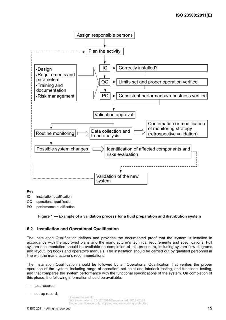
The validation process should provide documentary evidence that the system will consistently produce dialysis water, dialysis fluid, or substitution fluid meeting the quality requirements of ISO 13959 or ISO 11663. An example of the validation process is presented schematically in Figure 1.
NOTE The rationale for the validation process is given in Annex E.
The validation process consists of the following:
⎯ assignment of operational responsibility;
⎯ assignment of clinical responsibility;
⎯ assignment of legal responsibility;
⎯ Validation Plan;
⎯ Installation and Operational Qualification;
⎯ Performance Qualification;
⎯ revalidation as it relates to routine monitoring.
6.1 Validation Plan
The Validation Plan should be a clear and concise document covering the following:
⎯ description of relevant systems, equipment or processes;
⎯ current status of those systems, equipment or processes;
⎯ procedures for making changes to systems, equipment or processes;
⎯ planning and scheduling, including the addition of new systems, activities driven by change, and periodic review.
The Validation Plan should be approved by the person at the dialysis facility with overall responsibility for dialysis fluids.
Licensed to zeitakISO Store order #: 10-1252914/Downloaded: 2012-02-08Single user licence only, copying and networking prohibited
ISO 23500:2011(E)
© ISO 2011 – All rights reserved 15
Assign responsible persons
Plan the activity
IQ
OQ
PQ
Correctly installed?
Limits set and proper operation verified
Consistent performance/robustness verified
Validation approval
Routine monitoring
Validation of the new system
Possible system changes Identification of affected components andrisks evaluation
•Design •Requirements and parameters•Training anddocumentation•Risk management
Data collection and trend analysis
Confirmation or modificationof monitoring strategy (retrospective validation)
Key IQ installation qualification OQ operational qualification PQ performance qualification
Figure 1 — Example of a validation process for a fluid preparation and distribution system
6.2 Installation and Operational Qualification
The Installation Qualification defines and provides the documented proof that the system is installed in accordance with the approved plans and the manufacturer's technical requirements and specifications. Full system documentation should be available on completion of this procedure, including system flow diagrams and layout, log books and operator's manuals. The installation should be carried out by qualified personnel in line with the manufacturer's recommendations.
The Installation Qualification should be followed by an Operational Qualification that verifies the proper operation of the system, including range of operation, set point and interlock testing, and functional testing, and that compares the system performance with the functional specifications of the system. On completion of this phase, the following information should be available:
⎯ test records;
⎯ set-up record; Licensed to zeitakISO Store order #: 10-1252914/Downloaded: 2012-02-08Single user licence only, copying and networking prohibited
ISO 23500:2011(E)
16 © ISO 2011 – All rights reserved
⎯ calibration schedule;
⎯ sampling procedures;
⎯ maintenance (e.g. disinfection, filter changes, etc.) and monitoring (e.g. conductivity, microbiological analysis) plans;
⎯ record of operator(s) training.
6.3 Performance Qualification
The Performance Qualification should demonstrate the consistency and robustness of the system under local operational conditions. During this phase, information about system behaviour should be collected and action levels should be reviewed or defined. On completion of the Performance Qualification, the following information should be available:
⎯ test records;
⎯ chemical and microbial analyses;
⎯ key performance indicators [for example, pretreatment efficiency, reverse osmosis (RO) recovery/rejection rate, etc.];
⎯ (initial) trend analysis.
For newly installed systems, the person with overall clinical responsibility for dialysis (possibly supported by technical experts) may authorize use of dialysis fluid for patient treatments once chemical and microbiological analyses are available that show full compliance with the quality requirements of Clause 4, the manufacturer's specifications, and any applicable regulatory requirements.
6.4 Routine monitoring and revalidation
This subclause describes the monitoring activities to be conducted as part of the quality control and quality assurance process.
Routine monitoring should begin following the Performance Qualification (6.3) to ensure ongoing compliance with the dialysis water and dialysis fluid quality requirements set forth in Clause 4. Trend analysis of monitoring data should be used to provide advanced information on system performance, thus enabling a preventive rather than a reactive approach to system maintenance.
Monitoring is achieved with online and offline measurements. Online monitoring of suitable parameters (such as conductivity) provides immediate identification of deviations from normal operating conditions and can identify potential problems in their early stages, and could trigger specific additional offline measurements. A purely time-based offline sampling regime has inherent limitations for the monitoring of a continuous production process since deviations can occur between samples.
Fluid sampling for microbiological testing should be performed no sooner than 24 h after disinfection to avoid false negative results. When disinfection is performed on consecutive days, or more frequently, samples should be taken before, and as close as practicable to, a disinfection procedure.
Guidance on parameters that should be monitored is provided in Annex C, Table C.1.
A revalidation should be performed under the following circumstances:
⎯ modification of the maintenance and monitoring plans;
⎯ modification of the system;
⎯ changes in the requirements for dialysis fluid quality.
Licensed to zeitakISO Store order #: 10-1252914/Downloaded: 2012-02-08Single user licence only, copying and networking prohibited
ISO 23500:2011(E)
© ISO 2011 – All rights reserved 17
In the absence of system modification, regular revalidation is still required. This revalidation consists of a retrospective assessment of the routine results of the previous year (no additional tests are required for the revalidation process). The purpose of this review is to prove the adequacy of the maintenance and monitoring plan under the local operating conditions. The revalidation should include a report submitted to, and approved by, the person with overall clinical responsibility for dialysis.
7 Quality management
7.1 General
Quality control and quality assurance procedures should be established to ensure ongoing conformance to policies and procedures regarding fluid quality. This clause defines some of the monitoring activities to be performed at the dialysis facility as part of the quality assurance process. The test methods described in 7.2 do not represent the only acceptable methods available, but are intended to provide examples of acceptable methods. The frequency of monitoring is generally recommended by the equipment manufacturer or by local organizations that oversee dialysis facilities. In the absence of a manufacturer's recommendations, guidance on tests to include in a quality assurance monitoring programme can be found in Annex C. This guidance can also be used to supplement the manufacturer's recommendations.
The clinic should establish communications with the feed-water supplier so that the feed-water supplier is aware that the feed water is used for the production of dialysis fluid [i.e. for life-saving treatment on end-stage renal disease (ESRD) patients] and request the establishment of formal procedures to provide the clinic with correct and timely information about any change in the supplied water quality (for example, change of source or type of raw water treatment) or delivery (i.e. water supply interruptions). If such procedures cannot be established, additional monitoring of feed-water quality could be required.
7.2 Monitoring of fluid quality
7.2.1 Monitoring of dialysis water quality
Dialysis water quality should be monitored on a regular basis for the chemical and microbiological contaminants listed in 4.1.2 and 4.1.3. The monitoring schedule should be based on the results of the system validation. For an established water treatment system operating under stable conditions, chemical contaminants in dialysis water should be monitored at least annually. The exception is for total chlorine, which should be monitored as described in 7.3.5.
Methods for monitoring chemical and microbiological contaminants in dialysis water are given in ISO 13959 (see also 8.3).
For water treatment and distribution systems that are integrated into a single system and that have been validated to produce water meeting the quality requirements of ISO 13959, the manufacturer's recommendations for monitoring may be followed for the manufacturer's recommended maximum period of use according to the instructions for use, provided that there is assurance that the system is being operated under the validated conditions.
7.2.2 Monitoring of concentrate quality
Users do not have to test concentrates to demonstrate compliance with the requirements of ISO 13958 when using commercially available packaged chemicals intended for use in preparing liquid concentrates at a dialysis facility or when using commercially available liquid concentrates, provided that the concentrates are manufactured in accordance with the requirements of ISO 13958. If the user prepares concentrate from raw chemicals, the resulting concentrate should meet the requirements of ISO 13958.
Licensed to zeitakISO Store order #: 10-1252914/Downloaded: 2012-02-08Single user licence only, copying and networking prohibited
ISO 23500:2011(E)
18 © ISO 2011 – All rights reserved
7.2.3 Monitoring of dialysis fluid quality
Dialysis fluid quality should be monitored on a regular basis for the microbiological contaminants listed in 4.3.2 as described in 8.3.1. Methods for monitoring microbiological contaminants in dialysis fluid are described in 8.3.
NOTE 1 Tests for bacterial growth and endotoxins are not required if the system is fitted with a bacteria- and endotoxin-retentive filter validated by the manufacturer and operated and monitored according to the manufacturer's instructions, unless the manufacturer requires those tests in the instructions for use.
NOTE 2 It is not possible to monitor compliance with the bacterial quality requirements for substitution solutions using currently available culturing methods.
Because dialysis fluid is prepared from dialysis water and concentrates meeting the quality requirements of ISO 13959 and ISO 13958, respectively, and since the dialysis water distribution system and dialysis fluid delivery system are required to be constructed of materials that do not contribute chemical contaminants to the water, routine monitoring of chemical contaminants in the dialysis fluid is not required.
7.3 Monitoring of water treatment equipment
7.3.1 General
The following requirements relate to and help explain the guidance provided in Annex C. A brief description of the individual water treatment devices is provided in Annex B.
7.3.2 Monitoring of sediment filters
There is no easy test to determine the effectiveness of a sediment filter; however, pressure drop (∆P) across the filter can be used to determine when the filter is retaining particulate matter to the point that the filter will no longer allow the required water flow without an excessive reduction in pressure at the outlet of the filter. A backwash cycle is used as a preventive measure to remove particulate matter from the sediment filter and avoid the development of an excessive pressure drop. The frequency of backwashing should follow the manufacturer's recommendations. Sediment filter monitoring should include verification that the timer used to initiate backwashing cycles is set to the correct time of day. A log sheet should be developed to record the pressure drop measurements and timer verifications.
7.3.3 Monitoring of cartridge filters
Cartridge filters should be monitored on a regular basis. There is no easy test to determine the effectiveness of a cartridge filter in removing particulate matter; however, pressure drop (∆P) across the filter can be used to determine when the filter is retaining particulate matter to the point that the filter will no longer allow the required water flow without an excessive reduction in pressure at the outlet of the filter. A marked decrease in ∆P without a corresponding decrease in flow rate can indicate a loss of filter integrity. Cartridges are usually replaced when ∆P increases to some specified value or at a predetermined interval. A log sheet should be developed to record the pressure drop measurements.
7.3.4 Monitoring of softeners
Softener monitoring consists of: testing softened water for residual hardness; for automatically regenerating softeners, checking that the brine tank contains a sufficient supply of undissolved sodium chloride; and, for time-controlled softeners, checking that the timer indicates the correct time of day. The frequency of monitoring should be based on the hardness of the feed water and the capacity of the softener. When reverse osmosis is used, monitoring should be used to ensure that hardness limits established by the reverse osmosis machine manufacturer are not exceeded. A temporary rise in hardness will have a minimal effect on the performance of the reverse osmosis system, as calcium and magnesium are removed by reverse osmosis.
Testing for hardness should be performed using an ethylenediaminetetraacetic acid (EDTA) titration test, with “dip and read” test strips, or a similar method. Online hardness monitors are also available. If an online monitor is used, it should be used and maintained in accordance with the manufacturer's instructions.
Licensed to zeitakISO Store order #: 10-1252914/Downloaded: 2012-02-08Single user licence only, copying and networking prohibited

ISO 23500:2011(E)
© ISO 2011 – All rights reserved 19
Regardless of the method chosen, users should ensure that test accuracy and sensitivity are sufficient to satisfy the hardness monitoring requirements of the reverse osmosis machine manufacturer when the softener is used as pretreatment for a reverse osmosis system.
When timer-controlled softeners are used, it is recommended that the hardness of the water exiting the softener be measured as near as practicable to the end of the duty cycle. The hardness test at the end of the duty cycle will indicate the overall effectiveness of the water softener under worst-case conditions and will ensure that the softener is sized properly and that the regeneration schedule is adequate. Timers should be checked at the beginning of each day. For volume-controlled duplex softeners, testing for hardness can be performed at any time of the day.
The brine-softener tank should be monitored on a regular basis to ensure that enough salt is present in the brine tank to form saturated salt solution of sufficient volume for a minimum of one regeneration cycle. Salt used for regeneration should meet the specifications of the softener manufacturer. In particular, salt designated as rock salt should not be used for softener regeneration since it is not refined and typically contains sediments and other impurities that can damage O-rings and pistons and clog orifices in the softener control head. The frequency of monitoring should be based on the length of the duty cycle.
Water softeners should be fitted with a mechanism to prevent water containing the high concentrations of sodium chloride used during regeneration from entering the product-water line during regeneration.
Water hardness test results and verification of timer settings and the presence of salt pellets should be recorded in a water-softener log.
7.3.5 Monitoring of carbon media
The performance of carbon beds is monitored by measuring the total chlorine concentration in the water exiting the carbon bed, or exiting the first carbon bed when a series-connected pair of beds is used. It should be noted that sampling for total chlorine (the sum of free chlorine and chloramine) and allowing a maximum level of 0,1 mg/l of total chlorine is simpler than analysing for free chlorine and chloramine separately.
Testing for total chlorine can be accomplished using the N,N-diethyl-p-phenylenediamine (DPD)-based test kits, dip-and-read test strips based on Michler's thioketone (MTK or TMK), or other methods where comparable sensitivity and specificity can be demonstrated. Online monitors can also be used to measure total chlorine concentrations. If an online monitor is used, it should be used and maintained in accordance with the manufacturer's instructions. Whichever test system is used, it should have sufficient sensitivity and specificity to resolve the maximum levels described in 4.1.2 (Table 1).
Testing for total chlorine should be performed at the beginning of each treatment day prior to the patient's initiating treatment. Where chloramine is used to disinfect the potable water supply at a level of 1 mg/l or more, testing should be repeated prior to the beginning of each patient shift; if there are no set patient shifts, testing should be performed approximately every 4 h during operation. More frequent monitoring could be appropriate during temporary operation with a single carbon bed, which can occur following breakthrough of the first bed. In such instances, testing is performed on water exiting the second carbon bed in a series-connected pair. The decision to change the frequency of monitoring should be based on the past performance of the system and on whether changes in feed-water quality have occurred. Samples should be drawn when the system has been operating for at least 15 min. The analysis should be performed onsite, since total chlorine levels will decrease if the sample is not assayed promptly. Results of monitoring should be recorded in a log sheet.
7.3.6 Monitoring of chemical injection systems
Systems for chemical injection should be monitored according to the manufacturer's instructions. If a facility designs its own chemical injection system, procedures should be developed to ensure proper preparation of the chemical, adequate mixing of the injected chemical with the water flowing through the pretreatment cascade, and reduction to a safe level of the concentration of any chemical residuals before the point of water use. The facility should also verify that the injected chemical does not degrade the performance of downstream devices, such as the reverse osmosis system. Verification can be accomplished by testing samples from the chemical reservoir and the water line after the point of injection for at least three batches of chemical.
Licensed to zeitakISO Store order #: 10-1252914/Downloaded: 2012-02-08Single user licence only, copying and networking prohibited
ISO 23500:2011(E)
20 © ISO 2011 – All rights reserved
When the chemical to be injected is prepared at a facility from powder or by dilution of a liquid concentrate, the chemical injection reservoir should be labelled with the name of the chemical and its concentration, the date the solution was prepared, and the name of the person who mixed the solution. Each batch of chemical should be tested for correct formulation before use. A batch of chemical should not be used or transferred to the injection system reservoir until all tests are completed. The test results, and verification that they meet all applicable criteria, should be recorded and signed by the trained personnel performing the tests.
Protective clothing and an appropriate environment, including ventilation adequate to meet applicable environmental exposure limits, and National Standards or regulations should be provided when chemicals for injection are prepared in a dialysis facility.
7.3.7 Monitoring of reverse osmosis
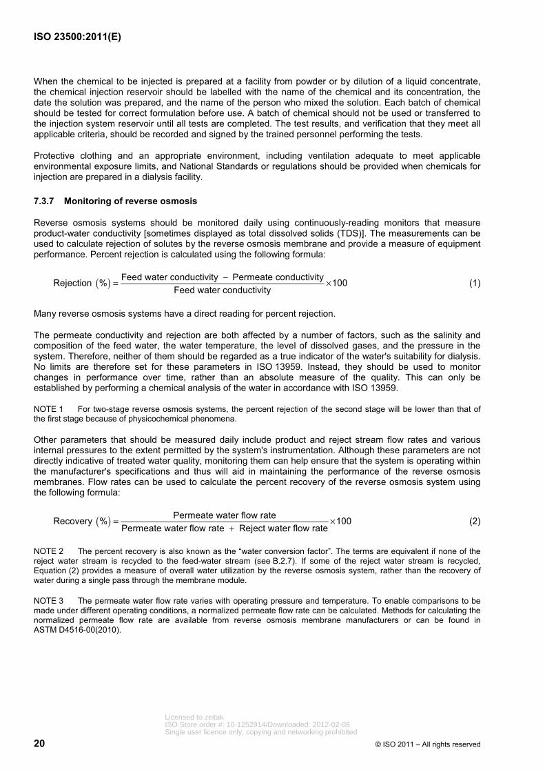
Reverse osmosis systems should be monitored daily using continuously-reading monitors that measure product-water conductivity [sometimes displayed as total dissolved solids (TDS)]. The measurements can be used to calculate rejection of solutes by the reverse osmosis membrane and provide a measure of equipment performance. Percent rejection is calculated using the following formula:
( ) Feed water conductivity Permeate conductivityRejection % 100Feed water conductivity
−= × (1)
Many reverse osmosis systems have a direct reading for percent rejection.
The permeate conductivity and rejection are both affected by a number of factors, such as the salinity and composition of the feed water, the water temperature, the level of dissolved gases, and the pressure in the system. Therefore, neither of them should be regarded as a true indicator of the water's suitability for dialysis. No limits are therefore set for these parameters in ISO 13959. Instead, they should be used to monitor changes in performance over time, rather than an absolute measure of the quality. This can only be established by performing a chemical analysis of the water in accordance with ISO 13959.
NOTE 1 For two-stage reverse osmosis systems, the percent rejection of the second stage will be lower than that of the first stage because of physicochemical phenomena.
Other parameters that should be measured daily include product and reject stream flow rates and various internal pressures to the extent permitted by the system's instrumentation. Although these parameters are not directly indicative of treated water quality, monitoring them can help ensure that the system is operating within the manufacturer's specifications and thus will aid in maintaining the performance of the reverse osmosis membranes. Flow rates can be used to calculate the percent recovery of the reverse osmosis system using the following formula:
( ) Permeate water flow rateRecovery % 100Permeate water flow rate Reject water flow rate
= ×+
(2)
NOTE 2 The percent recovery is also known as the “water conversion factor”. The terms are equivalent if none of the reject water stream is recycled to the feed-water stream (see B.2.7). If some of the reject water stream is recycled, Equation (2) provides a measure of overall water utilization by the reverse osmosis system, rather than the recovery of water during a single pass through the membrane module.
NOTE 3 The permeate water flow rate varies with operating pressure and temperature. To enable comparisons to be made under different operating conditions, a normalized permeate flow rate can be calculated. Methods for calculating the normalized permeate flow rate are available from reverse osmosis membrane manufacturers or can be found in ASTM D4516-00(2010).
Licensed to zeitakISO Store order #: 10-1252914/Downloaded: 2012-02-08Single user licence only, copying and networking prohibited

ISO 23500:2011(E)
© ISO 2011 – All rights reserved 21
When reverse osmosis is the final process in the water treatment system for removing chemical contaminants, analysis for the contaminants listed in Tables 1 and 2 should be done when the reverse osmosis system is installed to ensure that the limits specified in 4.1.2 are met. It is also recommended that chemical analyses be done when the following situations occur:
⎯ information is obtained from the water supplier that significant changes in the source water, such as seasonal variations, have occurred;
⎯ significant deviations are observed in process parameters, such as pH, conductivity, chlorine concentration and hardness, that can affect the performance of components of the water treatment system; and
⎯ reverse osmosis rejection rates decrease by more than 10 %.
All results of measurements of reverse osmosis performance should be recorded daily in an operating log that permits trending and historical review.
7.3.8 Monitoring of deionization
Deionizers should be monitored continuously using resistivity monitors that compensate for temperatures up to 25 °C and that are equipped with audible and visual alarms. Resistivity monitors should have a minimum sensitivity of 1 MΩ·cm (1 µS/cm). If the resistivity of the water at the outlet of a deionizer is less than 1 MΩ·cm the water should not be used for dialysis. When deionization is employed as the primary method for removing inorganic contaminants (reverse osmosis is not employed), or when deionization is necessary to polish reverse-osmosis-treated water, chemical analyses to ensure that the requirements of 4.1.2 are met should be performed when the system is installed. Resistivity monitor readings should be recorded on a log sheet twice each treatment day.
7.3.9 Monitoring of endotoxin-retentive filters
The performance of endotoxin-retentive filters in dialysis water distribution, bicarbonate concentrate distribution or dialysis fluid delivery systems can be monitored by testing the fluid that is directly exiting the filter for bacteria and endotoxins. Endotoxin-retentive filters should be fitted with a means of assessing filter integrity and fouling. One suitable means is to monitor the pressure drop (∆P) across the filter at a given product fluid flow rate using pressure gauges on the inlet (feed) and outlet (product) streams. Alternatively, product fluid flow rate can be measured at a given pressure drop. Such monitoring can indicate when membrane fouling has progressed to the point that membrane replacement or cleaning is needed. Monitoring is also necessary to ensure that the device is being operated in accordance with the manufacturer's instructions. Endotoxin-retentive filters operated in the cross-flow mode should also be monitored in terms of the flow rate of fluid being directed to drain at a given pressure drop. Results of pressure measurements and bacteria and endotoxin levels should be recorded on a log sheet.
7.4 Monitoring of water storage and distribution
NOTE The requirements in 7.4.1 to 7.4.3 relate to and help explain why the requirements were placed in Table C.1.
7.4.1 Monitoring of water storage tanks
For a system that distributes water to single-patient proportioning systems, routine monitoring of a water storage tank for total viable microbial count and endotoxin concentration is generally accomplished indirectly by monitoring the water at the first outlet to the distribution loop. For routine monitoring of a storage tank that supplies water to a central dialysis fluid delivery system, or when direct monitoring of a water storage tank is performed as part of a trouble-shooting process, the total viable microbial count and endotoxin concentration should be determined using samples drawn from a port at the outlet of the water storage tank. When a change has been made to an existing storage tank, more frequent testing should be considered to verify that bacteria or endotoxin levels are consistently within the allowed limits. The need for additional testing should be based on the original Validation Plan (see 6.1) and a risk analysis of the likely impact of the change on system performance. All total viable microbial counts and endotoxin results should be recorded on a log sheet and subject to trend analysis.
Licensed to zeitakISO Store order #: 10-1252914/Downloaded: 2012-02-08Single user licence only, copying and networking prohibited
ISO 23500:2011(E)
22 © ISO 2011 – All rights reserved
7.4.2 Monitoring of water distribution systems
Water distribution piping systems should be monitored for total viable microbial count and endotoxin concentration to demonstrate the adequacy of the disinfection programme described in 8.2. The total viable microbial count and endotoxins should not exceed the levels specified in 4.1.3. Monitoring should be accomplished by taking samples from the last outlet of the water distribution loop and the outlets supplying reuse equipment and bicarbonate concentrate mixing tanks. If the results of this testing are unsatisfactory, the disinfection programme should be re-evaluated and additional testing (for example, endotoxin-retentive filter inlet and outlet, reverse osmosis product water, and storage tank outlet) should be undertaken as part of a troubleshooting strategy to identify the source of contamination, after which appropriate corrective actions can be taken. Total viable microbial counts and endotoxin testing should be conducted on a regular schedule according to system validation data and local regulations and in accordance with 8.3.3 and 8.3.4. When a change has been made to an existing system, more frequent testing should be considered to verify that bacteria or endotoxin levels are consistently within the allowed limits. The need for additional testing should be based on the original Validation Plan (see 6.1) and a risk analysis of the likely impact of the change on system performance. All bacteria and endotoxin results should be recorded on a log sheet to permit identification of trends and the need for corrective action.
7.4.3 Monitoring of bacterial control devices
7.4.3.1 Monitoring of ultraviolet irradiators
Ultraviolet irradiators intended for use as a direct means of bacterial control should be monitored for radiant energy output. UV irradiators are available equipped with radiant energy intensity sensors. Either a visual alarm or an output meter is acceptable for determining if the UV lamp is emitting sufficient radiant energy. UV irradiators should be monitored at the frequency recommended by the manufacturer. Because the radiant energy decreases with time, annual lamp replacement is typically required. Periodic cleaning of the quartz sleeve may also be required, depending on the water quality. A log sheet should be used to indicate that monitoring has been performed.
7.4.3.2 Monitoring of ozone generators
Ozone generators should be monitored for ozone output at a level specified by the manufacturer. The output of the ozone generator should be measured by determining the ozone concentration in the water at the most distal point from the ozone generator. A test based on indigo trisulfonate chemistry, DPD, or the equivalent, or ozone-in-water test strips should be used to measure the ozone concentration. It is recommended that ozone concentration be measured each time disinfection is performed. An ozone-in-ambient-air test should be conducted on a periodic basis, as recommended by the manufacturer, to ensure compliance with National Standards and regulations for the permissible exposure limit. A log sheet should be used to indicate that monitoring has been performed.
7.4.3.3 Monitoring of hot water disinfection systems
Hot water disinfection systems should be monitored for temperature and time of exposure to hot water, as specified by the manufacturer. The temperature of the water should be recorded at a point farthest from the water heater; that is, where the lowest water temperature is likely to occur. It is recommended that the water temperature be measured each time a disinfection cycle is performed. A record that verifies successful completion of the heat disinfection should be maintained. Successful completion is defined as: meeting the temperature and time requirements specified by the equipment manufacturer.
7.5 Monitoring of concentrate preparation
7.5.1 Monitoring of mixing systems
Systems for preparing either bicarbonate or acid concentrate from powder or other highly concentrated media at a dialysis facility should be monitored according to the mixing system manufacturer's instructions to ensure appropriate dissolution. If a facility designs its own system, procedures should be developed and demonstrated to ensure proper mixing of the concentrate, including establishment of acceptable limits for tests of proper concentration. In this case, verification can be accomplished by testing a sample from each batch prepared over a 3 day period.
Licensed to zeitakISO Store order #: 10-1252914/Downloaded: 2012-02-08Single user licence only, copying and networking prohibited
ISO 23500:2011(E)
© ISO 2011 – All rights reserved 23
Acid and bicarbonate concentrates may be tested by measuring conductivity, density with a density meter or specific gravity with a hydrometer according to the manufacturer's instructions. Although not required, some manufacturers of concentrate powder or other highly concentrated media may provide allowable ranges for either the conductivity, density or the specific gravity of concentrates prepared from their powder. The use of pH, alone, as an indicator of proper dissolution is inappropriate for both acid and bicarbonate concentrates, because large variations in concentration do not produce significant changes in pH. Concentrates should not be used or transferred to holding tanks or distribution systems until all tests are completed. The test results and verification that they meet all applicable criteria should be recorded and signed by the individuals performing the tests.
7.5.2 Monitoring of additives
When additives are prescribed for a specific patient, the container holding the prescribed concentrates should be labelled with the name of the patient, the final concentration of the added electrolyte, the date and time when the prescribed concentrate was mixed, and the name of the person who mixed the additive. This information should also be recorded in accordance with the requirements of 4.4. The label should be affixed to the container when the mixing process begins.
7.6 Monitoring of concentrate distribution
A daily check to ensure that the appropriate acid and bicarbonate concentrate is connected to the corresponding concentrate delivery line is recommended if the storage tank is not permanently connected to its distribution piping.
Once a bicarbonate distribution system has been activated, dialysis fluid should be monitored weekly until sufficient data have been obtained to demonstrate the adequacy of the disinfection programme for the bicarbonate distribution system. The frequency of monitoring may then be reduced, but monitoring should be performed at least monthly. If elevated total viable microbial counts or endotoxin levels are found in the dialysis fluid, the disinfection programme for all systems involved in dialysis fluid preparation, including the bicarbonate concentrate distribution system, should be evaluated and revised. The frequency of monitoring should then be increased until it can be demonstrated that the revised disinfection programme is adequate to provide concentrate that allows preparation of dialysis fluid meeting the quality requirements of ISO 11663.
There are no published reports of acid concentrate supporting bacterial growth; therefore, it is not necessary to perform routine testing for total viable microbial count and endotoxins on those systems. However, it should be possible to disinfect these systems.
7.7 Monitoring of dialysis fluid proportioning
Dialysis fluid proportioning should be monitored following the procedures specified by the equipment manufacturer. When the user has specific requirements for monitoring dialysis fluid proportioning, such as when dialysis machine settings are changed to allow the use of concentrates with a different proportioning ratio, the user should develop procedures for routine monitoring of dialysis fluid electrolyte values, such as by monitoring sodium (Na+), potassium (K+), osmotic pressure, or conductivity.
8 Strategies for microbiological control
8.1 General
The strategy for controlling the proliferation of microorganisms in haemodialysis systems primarily involves appropriate system design and operation, and regular disinfection of the entire fluid system. This includes the reverse osmosis membranes (especially the clean side), the distribution piping, the inlet lines to the dialysis machines (located before the disinfection circuit of the dialysis machine), and the dialysis machines (which have their own disinfection circuit and programme). A key concept in ensuring compliance with the requirements of 4.1.3 and 4.3 is that disinfection schedules should be designed to prevent microbial proliferation, rather than being designed to eliminate microorganisms once they have proliferated to an unacceptable level. With this strategy, monitoring levels of microorganisms and endotoxin serves to demonstrate that the disinfection programme is effective, not to indicate when disinfection should be performed.
Licensed to zeitakISO Store order #: 10-1252914/Downloaded: 2012-02-08Single user licence only, copying and networking prohibited
ISO 23500:2011(E)
24 © ISO 2011 – All rights reserved
Microorganisms in fluid colonize surfaces resulting in biofilm formation, even when levels of microbial contamination are low. Microorganisms living within biofilms produce an extracellular polysaccharide or slime matrix, which protects them against disinfection. Microorganisms also excrete both simple and complex metabolites. Their effect on patients, and whether or not they are removed by endotoxin-retentive filters, is largely unknown. All strategies for microbial control of the system should, therefore, be proactive in order to limit biofouling (microbial growth and biofilm formation). It is of utmost importance that the disinfection procedure is applied from the start of the operation of the haemodialysis system. Once formed, biofilm is difficult, if not impossible, to eradicate.
The combined efforts of disinfection and employing strategies for bacterial control make it possible to minimize microbiological growth and biofilm formation.
The information given in this guidance is valid for the following:
⎯ water systems;
⎯ dialyser reprocessing systems;
⎯ central dialysis fluid delivery systems;
⎯ central sodium bicarbonate concentrate preparation and distribution systems.
8.2 Disinfection
Disinfection is the only effective method of diminishing and inactivating microflora.
First, and most of all, the frequency of disinfection is important. Disinfection should be performed on a regular basis to limit biofouling within the fluid pathways of the system. Depending on the circumstances, different levels of disinfection may be required to comply with the fluid quality requirements of Clause 4.
Second, all surfaces in the circuit should be included in the disinfection procedure. This includes the reverse osmosis membranes (especially the clean side), the distribution piping, the inlet lines to the dialysis machines (located before the disinfection circuit of the dialysis machine), and the dialysis machines (which have their own disinfection circuit and programme).
Third, the disinfection procedure, when applied with a given frequency and with inclusion of all critical areas, should be capable of minimizing the effects of biofouling.
Disinfection can be performed using heat or chemicals. UV lamps can be used to inactivate planktonic cells but are of no value against any biofilm that has formed in the system.
8.2.1 Microbiological aspects of fluid system design
The circuit downstream of the reverse osmosis system, including the clean side of the reverse osmosis membranes, the distribution piping, tanks and filters in the distribution piping, and the inlet lines to the dialysis machines, are to be maintained and disinfected so that it is possible to fulfil the microbiological requirements of ISO 11663.
Examples of good system design include
⎯ use of a recirculation-type system,
⎯ avoidance of dead ends and dead space areas,
⎯ a high quality finish to joints and connections,
⎯ use of materials compatible with the planned methods of disinfection, and
⎯ avoidance of storage tanks. If a storage tank is necessary it should be designed and constructed in such a manner that it can be cleaned and disinfected.
Licensed to zeitakISO Store order #: 10-1252914/Downloaded: 2012-02-08Single user licence only, copying and networking prohibited
ISO 23500:2011(E)
© ISO 2011 – All rights reserved 25
Once the water treatment system has been installed, water flow should be maintained to limit biofilm formation. The system design should also take into consideration preventive maintenance of the fluid distribution system, as well as education and training of staff in order to create awareness about sanitizing and microbiological control.
The disinfection programme could compensate for a weakness in system design but will not totally prevent the formation of biofilm, which can become difficult to eradicate.
8.2.2 Disinfection frequency
8.2.2.1 General
A key concept in ensuring compliance with the requirements of 4.1.3, 4.2.1, and 4.3.2 is that disinfection schedules should be designed to prevent bacterial proliferation, rather than being designed to eliminate bacteria once they have proliferated to an unacceptable level (i.e. above the action level). With this strategy, monitoring levels of bacteria and endotoxins serves to demonstrate that the disinfection programme is effective, not to indicate when disinfection should be performed.
A proper disinfection strategy is to be preventive and this should be applied from the start of operation. The disinfection strategy may be modified based on results obtained during validation and revalidation activities.
The disinfection frequency should not be based only on findings obtained during the first month of operation because microbiological growth in a fluid system starts as surface growth (biofilm formation) and little or nothing could be seen in fluid samples taken from a fluid system during that time, even if no disinfection is performed.
8.2.2.2 Water storage and distribution systems
Water storage and distribution systems should be disinfected on a schedule that allows the water quality recommendations of 4.1.3 to be met routinely. For integrated water treatment and distribution systems, the manufacturer's instructions for disinfection should be followed, provided routine monitoring shows that they are adequate to meet the requirements of 4.1.3. For systems assembled from individual components, the frequency of disinfection necessary to minimize biofouling will vary with the design of the system and, in the case of existing systems, the extent to which any biofouling has already occurred.
8.2.2.3 Concentrate mixing systems
Concentrate mixing equipment should be either
a) completely emptied, cleaned and/or disinfected according to the manufacturer's instructions, or
b) cleaned and/or disinfected using a procedure demonstrated by the facility to be effective in routinely producing concentrate that allows the recommendations of 4.2.1 to be met.
The mixing and disinfection data should be recorded for each mix and disinfection cycle using a dedicated log.
8.2.2.4 Concentrate distribution systems
Piped bicarbonate concentrate distribution systems should be disinfected either according to the manufacturer's instructions or using a procedure that has been demonstrated by the facility to be effective in routinely producing concentrate that allows the recommendations of 4.2.1 to be met. The disinfection interval should not exceed 1 week. If the manufacturer does not supply disinfection procedures, the user should develop and validate a disinfection protocol. It is recommended that monitoring of concentrate distribution systems be performed on a routine basis. When reusable concentrate containers are used to distribute bicarbonate concentrate, the containers and pick-up tubes should be disinfected at least weekly. Bicarbonate concentrate containers should be rinsed with treated water and stored inverted at the end of each treatment day. Pick-up tubes should also be rinsed with treated water and allowed to air dry at the end of each treatment day. Because there are no published reports of acid concentrate supporting bacterial growth, disinfection of acid concentrate distribution systems is not normally required. However, it should be possible to disinfect these systems.
Licensed to zeitakISO Store order #: 10-1252914/Downloaded: 2012-02-08Single user licence only, copying and networking prohibited
ISO 23500:2011(E)
26 © ISO 2011 – All rights reserved
8.3 Microbiological monitoring methods
8.3.1 General
The fluid system should be routinely monitored in order to verify that the microbiological quality indicators (bioburden represented by total plate count and endotoxin concentration) are being met.
The frequency of sampling should meet applicable local recommendations. If no such recommendations exist, the following is recommended.
a) Water system: The number of samples and positions of sampling should be based on the complexity and size of the water system. The frequency will depend on the analysis of the data collected during the validation and revalidation activities. Monthly monitoring is most frequently adopted but less frequent monitoring may be possible based on data collected during the validation and revalidation.
b) Dialysis fluid/haemodialysis machines without a validated bacteria- and endotoxin-retentive filter: Machines should be sampled on a regular basis to provide verification of the effectiveness of the disinfection process. The schedule of sampling will depend on the type of disinfection process being used. Each machine should be sampled at least once per year and different machines should be sampled on each occasion. Monthly monitoring is most frequently adopted.
c) It is not necessary to take samples of ultrapure dialysis fluid or substitution fluids if their production paths are fitted with bacteria- and endotoxin-retentive filters validated by the manufacturer and operated and monitored according to the manufacturer's instructions. It could be necessary to sample the dialysis fluid entering such bacteria- and endotoxin-retentive filters depending on the manufacturer's instructions for use of the filters; for example, when the instructions for use specify the quality of the fluid entering the filter. (See also Annexes D and E.)
The results of testing should be subjected to trend analysis. When results exceed the action levels, or in the case of a patient's pyrogenic reaction or suspected bacteremia/fungemia, an investigation and follow-up should be initiated. This investigation could include additional sampling and extra disinfection procedures carried out as per the manufacturer's recommendations.
8.3.2 Sample collection
8.3.2.1 Water sample sites
Samples are to be taken at outlets of the water distribution system.
Prior to sampling, the inside of the outlet can be disinfected, especially if no haemodialysis machine is attached. The reason for such disinfection is that, over time, residual water in an outlet will support microbial growth. The disinfection can be made by flushing the inside of the outlet with 70 % ethanol or iso-propanol. A sterile cotton swab wetted with alcohol can also be used. Exposure time is to be >15 s. In principle, it is sufficient to let out enough water to rinse off the alcohol (200 ml to 500 ml) prior to sampling. Alternatively, hoses can be disconnected from the tap and the taps opened and allowed to flush for 2 min to 3 min before aseptically collecting a sample.
Sample for cultivation and endotoxin analysis: Sample volume 5 ml to 1 000 ml or volume as specified by the laboratory. Containers for samples to be cultured should be sterile and containers for samples to be tested for endotoxins should be sterile and endotoxin-free.
8.3.2.2 Dialysis fluid samples
Dialysis fluid samples should be collected from a sampling port prior to the dialyser. The sample port should be designed to minimize the likelihood of contaminating the sample and should be capable of being effectively disinfected.
Licensed to zeitakISO Store order #: 10-1252914/Downloaded: 2012-02-08Single user licence only, copying and networking prohibited
ISO 23500:2011(E)
© ISO 2011 – All rights reserved 27
Many dialysis machines are equipped with dialysis fluid sample ports that can be accessed using a syringe. These sample ports may be disinfected with 70 % ethanol or iso-propanol and allowed to air dry. A sterile syringe (20 ml or larger) should then be used to aspirate dialysis fluid out of and into the port before filling the syringe. The filled syringe should then be discarded and a fresh sample of dialysis fluid collected using a new sterile syringe.
Alternatively, if the haemodialysis machine permits, samples can be collected immediately after the dialyser by disconnecting the effluent Hansen connector and aseptically collecting a “free/clean” catch sample after allowing dialysis fluid to run for 30 s to 60 s.
Sample for cultivation and endotoxin analysis: Sample volume 5 ml to 1 000 ml or a volume as specified by the laboratory. Containers for samples to be cultured should be sterile and containers for samples to be tested for endotoxins should be sterile and endotoxin-free.
8.3.3 Heterotrophic plate count
8.3.3.1 Storage of samples
Microbial analysis of water and dialysis fluid samples should be conducted as soon as possible after collection to avoid unpredictable changes in the microbial population. If samples cannot be analysed within 4 h of collection, follow the laboratory's instructions for shipping. Samples intended for colony counts should not be frozen.
Storage of samples for endotoxin analysis may be different from what is given above, provided the complete procedure follows the manufacturer's instructions for use of the LAL assay.
8.3.3.2 Analytical methods
8.3.3.2.1 Membrane filtration
Membrane filtration is filtration of the sample through a membrane filter with pore diameter 0,45 µm or less. Membrane filtration is a method used when the sample is to be concentrated to detect low levels of contamination (usually <1 CFU/ml). The volume to be filtered should be determined by the suspected level of contamination and be between 10 ml and 1 000 ml.
8.3.3.2.2 Spread plate technique
A pipette is used to apply 0,2 ml to 0,5 ml of a sample to a Petri dish (typically 90 mm in diameter) containing agar medium and spread over the surface of the agar. The detection limit of this technique is 5 CFU/ml when 0,2 ml of sample is used as the inoculum.
8.3.3.2.3 Pour plate technique
1 ml of sample is placed in a Petri dish and 15 ml to 20 ml of molten medium is added. The sample and medium are mixed carefully by gentle rotation and allowed to set. The time between addition of the sample and addition of the molten medium should not exceed 15 min. The plate is inverted and incubated. If 1 ml of sample is used, the detection limit of this technique is 1 CFU/ml.
Molten media should be <45 °C.
8.3.3.2.4 Dip samplers
Currently available dip samplers are not suitable for use in dialysis applications.
8.3.3.3 Cultivation conditions
A cultivation method has three elements: the cultivation medium, the incubation temperature, and the incubation time. Suitable cultivation conditions can be found in Table 5.
Licensed to zeitakISO Store order #: 10-1252914/Downloaded: 2012-02-08Single user licence only, copying and networking prohibited

ISO 23500:2011(E)
28 © ISO 2011 – All rights reserved
Table 5 — Cultivation techniques
Cultivation medium Incubation temperature Incubation time
Tryptone Glucose Extract Agar (TGEA) 17 °C to 23 °C 7 days
Reasoner's Agar No. 2 (R2A) 17 °C to 23 °C 7 days
NOTE 1 It is not necessary to use both media for routine monitoring.
For central sodium bicarbonate preparation and distribution systems, the cultivation medium should be supplemented with 4 % sodium bicarbonate.
NOTE 2 If dehydration of culture plates is a concern, then plates can be sealed using Petri-plate seals or placed in closed plastic bags during incubation.
NOTE 3 Colony counts of microbes in fluid distribution systems and other environmental samples are only relative counts. Counts will vary depending on the length of incubation and culture conditions. No matter what different conditions are used, not all viable cells will grow on artificial media [for example, viable but not culturable (VBNC)].
8.3.4 Bacterial endotoxin test
Bacterial endotoxins are assayed using the Limulus amoebocyte lysate (LAL) test. Current pharmacopoeias [United States (USP), European and Japanese Pharmacopoeias] acknowledge six different testing techniques.
Endotoxin testing requires education and should be performed by fully trained personnel.
Valid tests have to follow official applicable requirements and manufacturer's instructions.
NOTE It is important to use correct types of sample containers, labelled or validated for storage of endotoxin samples. Appropriate containers are usually specified by the testing laboratory or the manufacturer of the LAL testing kit.
9 Environment
The water treatment and storage system should be located in a secure area that is readily accessible only to personnel authorized by the dialysis facility. The location should be chosen with a view to minimizing the length and complexity of the distribution system. Access to the treatment system should be restricted to those individuals responsible for monitoring and maintenance of the system.
The layout of the water treatment system should provide easy access to all components of the system, including all meters, gauges and sampling ports used for monitoring system performance. An area for processing samples and performing onsite tests is also recommended. Critical alarms, such as those associated with deionizer exhaustion or low water levels in a storage tank, should be configured to notify staff in the patient treatment area, as well as in the water treatment room.
Water systems should include schematic diagrams that identify components, valves, sample ports and flow direction. Additionally, piping should be labelled to indicate the contents of the pipe and direction of flow. The use of text labels, such as “RO Water,” and colour-coded “arrow tape” provides a convenient means of identifying the pipe content and flow direction.
If water system manufacturers have not done so, users should identify major water system components and describe their function. How performance is verified, and what actions to take in the event that performance is not within an acceptable range, should be readily available to the user.
Licensed to zeitakISO Store order #: 10-1252914/Downloaded: 2012-02-08Single user licence only, copying and networking prohibited
ISO 23500:2011(E)
© ISO 2011 – All rights reserved 29
10 Personnel
Policies and procedures that are understandable and accessible are mandatory, along with a training programme that includes quality testing, the risks and hazards of improperly prepared concentrate, and bacterial issues. Operators should be trained in the use of the equipment by the manufacturer or should be trained using materials provided by the manufacturer. Additional training may be provided using materials from other sources. The training should be specific to the functions performed (i.e. mixing, disinfection, maintenance and repairs). Periodic audits of the operators' compliance with procedures should be performed. The user should establish an ongoing training programme designed to maintain the operator's knowledge and skills.
Licensed to zeitakISO Store order #: 10-1252914/Downloaded: 2012-02-08Single user licence only, copying and networking prohibited
ISO 23500:2011(E)
30 © ISO 2011 – All rights reserved
Annex A (informative)
Rationale for the development and provisions of
this International Standard
A.1 Scope
This clause provides the rationale for the requirements in Clause 1. It has long been known that chemical and microbiological contamination of dialysis fluid places haemodialysis patients at risk of acute and chronic adverse events. From the beginning, it was recognized that there was a problem with including fluid quality requirements in an International Standard directed at manufacturers of water treatment equipment or haemodialysis machines. Although a manufacturer might be responsible for providing equipment that, when assembled as a system, provides water, concentrate, or dialysis fluid that meets certain quality requirements, that manufacturer has no control over the equipment once it is installed. For example, the treated water quality could change if a water treatment system is not well maintained or if there is some change in the municipal water feeding the system. Therefore, fluid quality standards were established independent of the standards for the equipment used to prepare those fluids. Since the day-to-day responsibility for maintaining fluid quality lies with the healthcare professionals at each dialysis facility under the leadership of the facility's medical director, this International Standard was prepared to provide guidance to those healthcare professionals on how to manage fluid preparation systems so as to comply with the requirements of the fluid quality standards.
A.2 Chemical contaminants in dialysis water
This clause provides the rationale for the requirements in 4.1.2. ISO 13959 sets forth maximum levels of chemical contaminants in three categories: chemicals known to have particular toxicity for haemodialysis patients, chemicals included in drinking-water standards, and physiological substances that can adversely affect the patient if present in the dialysis fluid in excessive amounts. The rationale for including particular chemicals in ISO 13959, and for setting their maximum levels, is set forth in Annex A of ISO 13959:2009.
A.3 Microbiological contaminants in dialysis water
This clause provides the rationale for the requirements in 4.1.3. ISO 13959 sets forth maximum levels of bacteria and endotoxins in dialysis water, along with action levels for these contaminants. The rationale for the maximum levels of bacteria and endotoxins is set forth in Annex A of ISO 13959:2009.
A.4 Requirements for concentrate
The rationale in this clause addresses the requirements in 4.2. Requirements for commercially available concentrates are given in ISO 13958. It was decided not to recommend limits on bacteria and endotoxins for concentrate prepared at a facility, even for bicarbonate concentrate. This decision was based on the difficulty of performing cultures and endotoxin assays in samples with high concentrations of salts. High concentrations of bicarbonate require special culturing techniques and are inhibitory in the LAL assay. It was determined that it was unreasonable to require an individual dialysis facility to meet the special conditions required for proper testing of bicarbonate concentrate and that patients would be adequately safeguarded by the quality recommendations for the water used to prepare the concentrate and for the final dialysis fluid. For users who are interested in determining bacterial levels and endotoxin concentrations as part of a troubleshooting investigation, guidelines on performing cultures and endotoxin assays in bicarbonate concentrate are included in 8.3.3.3 and A.10.
Licensed to zeitakISO Store order #: 10-1252914/Downloaded: 2012-02-08Single user licence only, copying and networking prohibited
ISO 23500:2011(E)
© ISO 2011 – All rights reserved 31
A.5 Microbiological contaminants in dialysis fluid
The rationale in this clause addresses the requirements in 4.3. ISO 11663 sets forth maximum levels of bacteria and endotoxins in three categories of dialysis fluid: standard dialysis fluid; ultrapure dialysis fluid; and online-prepared substitution fluid. Where appropriate, action levels for bacteria and endotoxins are also given. The rationale for the maximum levels of bacteria and endotoxins is set forth in Annex A of ISO 11663:2009.
ISO 13959 sets a maximum allowable level for endotoxins in dialysis water of 0,25 EU/ml, while ISO 11663 sets a maximum allowable level for endotoxins in dialysis fluid of 0,5 EU/ml. The level for dialysis fluid is set higher than that for dialysis water in recognition that powder concentrates can contribute endotoxins, but not volume, to the final dialysis fluid. No such accommodation is made for bacteria since most bacteria will not survive in a viable form in powder concentrate.
A.6 Monitoring of carbon
The rationale in this clause addresses the requirements in 7.3.5. Intensive monitoring of carbon beds is recommended because of the long history of adverse events related to chloramine contamination of dialysis fluid (Ward, 1996). Chloramine concentrations in municipal water can change from day to day and the capacity of carbon beds to remove chloramine can vary with the pH and temperature of the water, the nature of the chloramine compounds present, and the presence of other substances in the water. The dependence of chloramine removal on multiple factors makes the performance of carbon beds unpredictable. Therefore, patient safety can only be ensured by intensively monitoring the performance of the carbon bed. Configuring carbon beds in series and sampling from a port located between the two beds provides one margin of protection against chloramine breakthrough. When chloramine is first detected in the effluent from the first bed, the second bed will still have some capacity for chloramine removal. This reserve capacity allows the user to conveniently replace the exhausted bed without risk to patients. The exhausted bed is discarded, the second bed is moved into the first position, and a new bed is placed in the second position. A new bed of virgin carbon should be used for replacement. In situations where chloramine is not used to disinfect the water, and the ammonia level in the water is low, one carbon bed or a carbon cartridge filter with a shorter EBCT could be sufficient. Carbon cannot be regenerated in a dialysis facility, and the use of regenerated carbon is prohibited. Backwashing of carbon beds does not regenerate the carbon, although it can allow more efficient use of the bed's capacity by removing channels that can form in the bed during routine operation. The recommendation that the water purification system should operate for at least 15 min, before samples of water from a carbon bed are drawn, is to guard against inadvertently sampling water that has been in the bed for an extended period.
A.7 Strategies for microbiological control
The rationale in this clause addresses the requirements in 8.1. All microbial growth in a fluid system involves growth on surfaces. In most cases, the microbial growth starts on surfaces and consequently little or nothing of the microbial development in the fluid system is recorded by taking fluid samples. The surface growth occurs in patches in the earlier stages and is difficult to analyse.
No testing is able to show a complete picture of bacterial growth and the tests described and referred to in this International Standard do not measure many microbial contaminants, including: cell wall fragments from microorganisms; nucleic acids DNA and RNA; and metabolites of various kinds.
For this reason, a proactive disinfection programme is recommended to combat bacterial growth in the water and dialysis fluid system.
A.8 Heterotrophic plate count
The rationale in this clause addresses the requirements in 8.3.3. Sensitive culturing methods should be used to measure the low total viable microbial counts permitted for water used for haemodialysis applications. The membrane filter technique is particularly suited for this application because it permits large volumes of water
Licensed to zeitakISO Store order #: 10-1252914/Downloaded: 2012-02-08Single user licence only, copying and networking prohibited
ISO 23500:2011(E)
32 © ISO 2011 – All rights reserved
to be assayed. Because the membrane filter technique might not be readily available in clinical laboratories, the spread plate assay or the pour plate assay can be used as an alternative for water and standard dialysis fluid (Bland, 1995). If the spread plate assay is used, a calibrated loop should not be used to apply sample to the plate. The sensitivity of an assay performed with a calibrated loop is low. A standard calibrated loop transfers 0,001 ml of sample to the culture medium, so that the minimum sensitivity of the assay is 1,000 CFU/ml. This sensitivity is unacceptable when the maximum allowable limit for microorganisms is 100 CFU/ml. Therefore, when the spread plate method is used, a pipette should be used to place 0,2 ml to 0,5 ml of water or dialysis fluid on the culture medium. The pour-plate method may be used as an alternative method to the spread-plate method. If a sample volume of 1 ml is used, the detection limit of the pour-plate method is 1 CFU/ml.
Culture results obtained using the methods outlined in this International Standard are only a relative indicator of the bioburden in the water or dialysis fluid and do not provide a measure of the absolute bacterial burden. The original clinical observations on which the microbiological requirements were based used standard methods agar (SMA), a medium containing relatively few nutrients (Favero, et al., 1974). Later, the use of trypticase soy agar (TSA), a general purpose medium for isolating and cultivating fastidious organisms, was recommended because it was thought to be more appropriate for culturing bicarbonate-containing dialysis fluid. However, several studies have shown that the use of nutrient-poor media, such as tryptone glucose extract agar (TGEA) or Reasoner's Agar No. 2 (R2A), results in an increased recovery of bacteria from water (Ledebo and Nystrand, 1999; van der Linde, et al., 1999; Pass, et al., 1996; Reasoner and Geldreich, 1985). Extending the culturing time up to 7 days and using incubation temperatures of 23 °C to 28 °C have also been shown to increase the recovery of bacteria compared to incubation for 48 h at 35 °C to 37 °C (Ledebo and Nystrand, 1999; Pass, et al., 1996; Reasoner and Geldreich, 1985).
When monitoring for microbial contamination in ultrapure dialysis fluid, the maximum allowable level of bacteria requires that culturing be performed using the membrane filtration method with a minimum of 10 ml of ultrapure dialysis fluid being passed through the filter. The use of larger volumes (up to 1 000 ml) will provide greater sensitivity, but the improved sensitivity needs to be balanced against the increased risk of contamination in collecting and handling the sample. The addition of 2 % to 8 % sodium bicarbonate to the medium can enhance the recovery of organisms (Nystrand and Nurbo, 1996). Even with these more sensitive techniques, compliance with the stringent requirement that online-prepared substitution fluid be sterile cannot be demonstrated by culturing; it has to be ensured by use of a validated process. Monitoring of the production of online-prepared substitution fluid will depend on the production system and should be performed according to the manufacturer's instructions.
Furthermore, the culturing conditions recommended in this International Standard could fail to identify the presence of some organisms. Specifically, the recommended methods might not detect the presence of various nontuberculous mycobacteria that have been associated with several outbreaks of infection in dialysis units (Bolan, et al., 1985; Lowry, et al., 1990). Also, the recommended methods will not detect fungi and yeast, which have been shown to contaminate water used for haemodialysis applications (Klein, et al., 1990).
The microbiological purity of packaged liquid concentrates and dry powder cartridges is the responsibility of the manufacturer. Monitoring of bicarbonate concentrate produced at a dialysis facility from powder and water, though not required routinely, may be undertaken as part of a troubleshooting investigation. The sodium content of TSA is sufficient for use in culturing bicarbonate concentrate without supplementation. However, salt tolerance studies showed that optimal growth of organisms found in bicarbonate concentrate occurred when the sodium chloride concentration was approximately 3 to 6 % (Bland, et al., 1987). Therefore, if a low salt medium, such as Reasoner's 2A or TGEA, is used to monitor microbial contamination in bicarbonate concentrate, it could be necessary to supplement the media with 4 % sodium bicarbonate.
A.9 Cultivation conditions
The rationale in this clause addresses the requirements in 8.3.3.3. Since dialysis is not stopped between sampling and obtaining the results of the tests, a long incubation time of 7 days is of no disadvantage or practical importance. However, significant contamination might be detected earlier by performing intermediate counts (e.g. every 2 days).
Licensed to zeitakISO Store order #: 10-1252914/Downloaded: 2012-02-08Single user licence only, copying and networking prohibited
ISO 23500:2011(E)
© ISO 2011 – All rights reserved 33
A.10 Bacterial endotoxin test
The rationale in this clause addresses the requirements in 8.3.4. Bicarbonate concentrate inhibits the LAL assay. Inhibition is caused by the high concentration of solutes in the concentrate and the pH. In the gel-clot assay, this inhibition results in a failure of the positive control to clot. In kinetic assays, inhibition results in a failure to recover the product positive control to within −50 % to +200 % of the nominal value.
Dilution of the bicarbonate concentrate with water is the usual method for overcoming inhibition. A minimum dilution of 1:16 is necessary; however, higher dilutions are recommended for more sensitive assays: for example, a 1:20 dilution is recommended when using an assay with a sensitivity of 0,03 EU/ml. Dilution reduces the detection limit of the assay. In kinetic methods, the sensitivity is the lowest concentration used to construct the standard curve. A kinetic assay is recommended for monitoring the quality of online-prepared substitution fluid because kinetic assays generally are more sensitive than gel-clot assays.
Standard gel-clot tests are incubated at 37 °C for the time recommended by the manufacturer. At the end of the recommended time, the tubes are inverted to detect the presence of a clot. A positive test will have a clot, which will remain in the end of the tube as long as it is not shaken or bumped. A negative test will not have a clot and will tend to flow out of the tube, when inverted. A clot that is semisolid and flows slowly is classified as a negative clot. For example, when bicarbonate concentrate is tested using a gel-clot assay with a sensitivity of 0,03 EU/ml and the concentrate is diluted 1:20 (1,0 ml concentrate plus 19 ml LAL reagent water or equivalent), the positive control sample should clot, indicating that there is no inhibition of the assay. If the diluted bicarbonate concentrate sample clots, it indicates that the sample contains at least 0,6 EU/ml of endotoxins. A new version of the gel-clot assay has a matched positive control, which simplifies the testing and increases the reliability of the results.
Licensed to zeitakISO Store order #: 10-1252914/Downloaded: 2012-02-08Single user licence only, copying and networking prohibited
ISO 23500:2011(E)
34 © ISO 2011 – All rights reserved
Annex B (informative)
Equipment
B.1 General
This annex provides a brief description of the different components that may be included in systems to treat and distribute water and dialysis fluid and to prepare and distribute concentrates for haemodialysis applications. Two types of systems are used: systems in which dialysis water is distributed to a dialysis machine at an individual patient treatment station, which prepares and controls the dialysis fluid for use at that station; and central dialysis fluid delivery systems, which prepare dialysis fluid centrally and supply it to multiple-patient treatment stations. Since feed-water quality and product-water requirements can vary from facility to facility, not all of the components described in the following clauses will be necessary in every water treatment and distribution system. Also, not every dialysis facility will prepare concentrate at the dialysis facility. Requirements for water treatment equipment used for haemodialysis and related therapies can be found in ISO 26722 and requirements for equipment used to prepare concentrates at a dialysis facility can be found in ISO 13958.
Routine dialysis requires a well-functioning water treatment and distribution system, since dialysis cannot be performed without an adequate supply of water. In addition, certain components of the water treatment and distribution system are critical to its operation. An example of such a critical component is the circulating pump in an indirect feed system. A dialysis facility should develop contingency plans to cover the failure of its water treatment and distribution system or a critical component of that system. Such contingency plans should describe how to deal with events that completely prevent dialysis from being performed, such as failure of the facility's municipal water supply or electrical service following a natural disaster or water main break. Other plans should address how to deal with sudden changes in municipal water quality, as well as with failure of a critical component of the water treatment and distribution system. Similar contingency plans should be developed to deal with the failure of concentrate preparation systems.
B.2 Water treatment systems
B.2.1 General
Water treatment systems consist of three basic sections: a pretreatment section that conditions the water supplied to the primary purification device, which may be followed by other devices that increase final water quality. The pretreatment section commonly includes a sediment filter, cartridge filters capable of retaining particles of various sizes, a softener and carbon beds. The primary purification process most commonly used is reverse osmosis, which may be followed by deionization and ultrafiltration for polishing the product water from the reverse osmosis system. Whether a particular device is included in an individual water purification system will be dictated by local conditions.
This clause provides a brief description of the principal equipment used to purify water used in haemodialysis applications. Devices used to treat water for haemodialysis should comply with the requirements of ISO 26722, including certain design and performance specifications for individual water treatment devices.
Subclauses B.2.2 to B.2.9 provide general information. Design and instrumentation of individual water treatment devices may vary from these general descriptions. For example, softeners may be configured as a single resin bed that is regenerated outside the normal operating hours of the dialysis unit, or they may have a dual-bed configuration that allows one bed to be regenerated while the other is used to provide water for normal dialysis operations.
Depending on the feed-water quality and product-water requirements, not every component in this clause might be required in a given facility. Likewise, additional components can be required in certain circumstances.
Licensed to zeitakISO Store order #: 10-1252914/Downloaded: 2012-02-08Single user licence only, copying and networking prohibited
ISO 23500:2011(E)
© ISO 2011 – All rights reserved 35
For example, carbon might not provide adequate chloramine removal if the water contains substances, such as polyphosphates, that mask the reactive sites on the carbon particles. In those circumstances, other processes, such as infusion of sodium bisulfite, can be required to achieve product water that meets the requirements of 4.1.2.
Users are encouraged to obtain detailed descriptions of all water treatment components, together with operating manuals and maintenance procedures, from the manufacturer or the supplier of the water treatment and distribution system.
B.2.2 Sediment filters
Permanent, backwashable sediment filters, also known as “bed filters”, are frequently located at or near the beginning of haemodialysis water treatment systems and are intended to remove relatively coarse particulate materials from incoming water. Although a single filtration medium may be used, bed filters known as multimedia filters are more commonly selected. These units contain multiple layers, each layer retaining progressively smaller particles. In this way, the bed is used to its fullest extent; the largest particles are removed in the first layer contacted by the water and the smallest in the final layer.
As the bed accumulates particulate material, open passages begin to clog and resistance to the water flowing through the filter increases. Ultimately, the increased resistance to flow will lead to a reduction in water supply to downstream components. To prevent this situation from occurring, bed filters are cleaned by periodic backwashing, which is accomplished either manually or by using a timer-activated control valve. Bed filters should be fitted with gauges to measure the hydrostatic pressure at the filters' inlet and outlet. These values can be used to determine the dynamic pressure drop across the filter (delta pressure or ∆P), which serves as an index of resistance to flow and provides a basis, together with the manufacturer's recommendations, for setting the frequency of backwashing.
B.2.3 Cartridge filters
Cartridge filters consist of a cylindrical cartridge of the filter medium with a central drainage core. The cartridge is contained within a filter housing with seals to separate the feed and product-water streams. In the pretreatment cascade, transparent filter housings can be useful because they allow any carbon or resin leakage to be seen without the need to break the integrity of the system. The housing can be cleaned to remove any algae growth when the filter cartridge is changed. For this reason, use of opaque housings for cartridge filters is recommended, but not required. If transparent housings are used, they should not be exposed to natural light, in order to minimize proliferation of algae. Cartridge filters should be fitted with gauges to measure the hydrostatic pressure at the filters' inlet and outlet. Although cartridge filters may be installed at the inlet to a water treatment system, their usual application is as a final filtration step prior to reverse osmosis. Resistance to flow through the filter increases as the cartridge accumulates particulate material, as indicated by an increase in ∆P. When the maximum ∆P recommended by the filter manufacturer is reached, the cartridge should be replaced according to the manufacturer's instructions.
B.2.4 Softeners
Water that contains calcium or magnesium can form relatively hard deposits and is called “hard water”. Water that has had these elements replaced by sodium ion exchange is called “soft water”, hence the term “softener” is used. Softeners also remove other polyvalent cations, most notably iron and manganese, although they are somewhat limited in this regard. However, if significant concentrations of iron and manganese are present, special procedures should be implemented in order to reduce those concentrations to levels that do not interfere with the softening process or cause membrane fouling. The primary use of softeners in haemodialysis water systems is to prevent hard water deposits from fouling reverse osmosis membranes.
A softener is a cylinder or vessel that contains insoluble spheres or beads, called “resin”, to which sodium ions are attached. During operation, exchangeable sodium ions in the resin are progressively replaced by calcium and magnesium ions. When all the sodium ions have been used, the resin bed has reached a condition referred to as “exhaustion”. Prior to exhaustion, softeners should be restored; that is, new exchangeable sodium ions are placed on the resin by a process known as “regeneration”, which involves exposure of the
Licensed to zeitakISO Store order #: 10-1252914/Downloaded: 2012-02-08Single user licence only, copying and networking prohibited
ISO 23500:2011(E)
36 © ISO 2011 – All rights reserved
resin bed to a highly concentrated sodium chloride solution. The concentrated sodium chloride solution is prepared in a separate brine tank, from which the solution is drawn during the regeneration process. A control valve on the softener regulates the regeneration and service cycles.
Automatically regenerated water softeners should be fitted with a mechanism to prevent water containing the high concentration of sodium chloride used during regeneration from entering the product-water line during regeneration. For softeners with a time-controlled regeneration cycle, the face of the timer should be visible to the user.
B.2.5 Carbon
Carbon systems, often referred to as carbon filters, are the principal means of removing both free chlorine and chloramine. Removal of chloramine to a maximum level of 0,1 mg/l and removal of free chlorine to a maximum level of 0,5 mg/l are necessary to protect haemodialysis patients from red blood cell haemolysis. In addition, free chlorine can also degrade some reverse osmosis membranes, depending on the membrane material. Determining the level of chloramine typically involves measuring both total chlorine and free chlorine and assigning the difference in concentrations to chloramine. To permit a single test to be used, a maximum allowable level for total chlorine was set at the maximum allowable level for chloramine (0,1 mg/l).
In addition to removing free chlorine and chloramine, carbon also adsorbs a wide variety of other substances, including both naturally occurring and synthetic organic compounds. The capacity of carbon to remove free chlorine and chloramine can be reduced when other substances “mask” reactive sites on the carbon media. In addition, the rate of free chlorine and chloramine removal is reduced as pH increases or as temperature decreases. The net effect of those variables is that the finite capacity of carbon beds to remove free chlorine and chloramine cannot be predicted with any certainty. Therefore, their performance needs to be monitored frequently.
Carbon systems should be adapted specifically to the maximum anticipated water flow rate of the system. When carbon is used for the removal of chloramine at a level of 1 mg/l or more, two carbon beds should be installed in a series configuration. A means should be provided to sample the product water from the first bed. A sampling port should also be installed following the second bed for use in the event of total chlorine breaking through the first bed. In situations where chloramine is not used to disinfect the water, and the ammonium level in the water is low, one carbon bed or carbon cartridge filters could be sufficient. Exhausted carbon media should be discarded and replaced with new media, according to a replacement schedule determined by regular monitoring. For example, when testing between the beds shows that the first bed is exhausted, the second bed should be moved into the first position, the second bed replaced with a new bed, and the exhausted bed discarded. When samples from the first sampling port are positive for total chlorine, operation may be continued for a short time (up to 72 h) until a replacement bed is installed, provided that samples from the second sampling port remain negative. It was recognized that it might not be practical to rotate the bed positions in installations that use large, backwashable carbon beds. However, there was concern that the capacity of the second bed could decrease unpredictably and no longer provide adequate backup if there was breakthrough of the first bed. For this reason, replacing both beds if bed rotation was not possible was recommended.
Granular activated carbon with an iodine number greater than 900 is considered optimal for chlorine/chloramine removal. When granular activated carbon is used as the medium for the removal of chloramine from water containing >1 mg/l chloramine, each bed should have an empty bed contact time (EBCT) of at least 5 min at the maximum product-water flow rate (a total EBCT of at least 10 min). Some source waters, such as those with a high organic content, could require alternative types of carbon that are more resistant to organic fouling. These types of carbon may have iodine numbers less than 900. When other forms of carbon or granular activated carbon with an iodine number of less than 900 are used, the manufacturer should provide performance data to demonstrate that each bed has the capacity to reduce the total chlorine concentration in the feed water to less than 0,1 mg/l when operating at the maximum anticipated flow rate for the maximum time interval between scheduled testing of the product water for total chlorine. Regenerated carbon should not be used. Some granular activated carbon contains aluminium, which can elute from the carbon and add to the burden of aluminium to be removed by reverse osmosis or ion exchange. The use of acid-washed carbon minimizes this source of aluminium in the water.
Licensed to zeitakISO Store order #: 10-1252914/Downloaded: 2012-02-08Single user licence only, copying and networking prohibited
ISO 23500:2011(E)
© ISO 2011 – All rights reserved 37
Where practical, portable dialysis systems supplied with water known to contain chloramine should include two carbon beds in series, which together provide a 10 min EBCT. Where that is not practical, alternative technologies can be used provided there is a redundant means of chloramine removal and that a total chlorine concentration of less then 0,1 mg/l is verified in a sample collected after the primary device before each treatment. Possible alternatives include: a granular activated carbon bed followed by a dense carbon block; and two carbon block filters in series.
Carbon beds used for free chlorine and chloramine removal are sometimes arranged as series-connected pairs of beds so that they need not be overly large. The beds within each pair are of equal size and water flows through them are parallel. For removal of chloramine from water containing >1 mg/l, each pair of beds should have a minimum empty bed contact time of 5 min at the maximum flow rate through the bed. When series-connected pairs of beds are used, the piping should be designed to minimize differences in the resistance to flow from inlet and outlet between each parallel series of beds to ensure that an equal volume of water flows through all beds.
Although treatment of water by carbon is the method usually used to meet the requirement of 4.1.2 for total chlorine, it was recognized that, in certain situations, carbon might not adequately remove chloramine. Inadequate removal of chloramine might occur when chloramines in the form of naturally occurring N-chloramines are present or when practices such as the use of high pH or the inclusion of orthophosphate or polyphosphates are used. If the pH of the incoming water is out of the range specified by the manufacturer, the carbon might not function properly and deplete rapidly. In other situations, such as acute dialysis with portable water treatment systems, it could be impractical to use the volume of carbon required to ensure adequate chloramine removal. In such circumstances, other strategies for chloramine removal may be needed to supplement carbon. Acid injection can be used to decrease pH (see B.2.6), anion exchangers (also known as organic scavengers) can be installed before carbon beds to remove organic matter and other substances that might foul carbon beds, and dealkalizers can be used to reduce alkalinity. It is known that adding sodium bisulfite prior to the reverse osmosis system has been successful in eliminating chloramine in haemodialysis applications. Ascorbic acid has also been added to the acid concentrate used to eliminate chloramine from the final dialysis fluid (Ward, 1996). It should be noted that a minimum contact time is required for ascorbic acid to neutralize chloramine in water. If ascorbic acid is being used to neutralize chloramine, and if unexplained red blood cell destruction or anaemia occurs, the effectiveness of the ascorbic acid neutralization of chloramine should be investigated. Other means of removing chloramine, such as redox alloy media and ultraviolet irradiation, are used in the pharmaceutical and electronics industries. These processes are currently being evaluated for haemodialysis applications. The final choice of a system for chloramine removal in haemodialysis settings will depend on local conditions and might need to include more than one of the processes outlined above.
B.2.6 Chemical injection systems
Chemical injection systems may be used in the pretreatment section of a water purification system to supplement the physical purification processes described in the previous clauses. Applications of chemical injection include the addition of sodium bisulfite to remove chloramine and the addition of acid to adjust pH.
Chemical injection systems consist of a reservoir that contains the chemical to be injected, a metering pump, and a mixing chamber located in the main water line. Chemical injection systems also include some means of regulating the metering pump to control the addition of a chemical. This system should be designed to tightly control the addition of the chemical. The control system should ensure that a chemical is added only when water is flowing through the pretreatment cascade and that it is added in fixed proportion to the water flow or based on some continuously monitored parameter, such as pH, using an automated control system. If an automated control system is used to inject the chemical, the controlling parameter should be independently monitored. There should also be a means of verifying that the concentrations of any residuals arising from the chemical added to the water are reduced to a safe level before the water reaches its point of use.
When acid is added to adjust pH, a mineral acid should be used; organic acids can act as a nutrient and allow bacteria to proliferate.
Reservations were expressed about the addition of chemicals to the water. However, it was recognized that the addition of chemicals could be necessary, in some circumstances, if a facility is to meet the maximum contaminant levels set forth in 4.1.2. For example, if the municipal water contains high levels of N-chloramines or chloramine in the presence of orthophosphate or polyphosphate, injection of sodium bisulfite can be one of the few options available for chloramine removal.
Licensed to zeitakISO Store order #: 10-1252914/Downloaded: 2012-02-08Single user licence only, copying and networking prohibited
ISO 23500:2011(E)
38 © ISO 2011 – All rights reserved
If chemical injection is used in the pretreatment cascade, users should ensure that the addition of the chemical does not interfere with the operation of subsequent purification processes, including the primary purification process. For example, the performance of thin-film composite reverse osmosis membranes might be affected by the pH of the feed water. At pH levels below 7, the rejection of fluoride can be substantially reduced, compared to its rejection at a pH of 8.
B.2.7 Reverse osmosis
Reverse osmosis (RO) systems have become widely used in haemodialysis water treatment systems, largely because these devices remove dissolved inorganic solutes, as well as bacteria and bacterial endotoxins.
The following requirements apply to reverse osmosis systems:
a) when used to prepare water for haemodialysis applications, either alone or as the last stage in a purification cascade, reverse osmosis systems should be shown to be capable, at installation, of meeting the requirements of ISO 13959, when tested with the typical feed water of the user;
b) reverse osmosis devices should be equipped with online monitors that allow determination of rejection rates and product-water conductivity. The product-water conductivity monitor should activate audible and visual alarms when the product-water conductivity exceeds the preset alarm limit. The alarms should be capable of notifying staff in the patient care area when reverse osmosis is the last chemical purification process in the water treatment system. Monitors that measure resistivity may be used in place of conductivity monitors.
The RO membrane separation process components are a semipermeable membrane, typically in a spiral-wound configuration, a pump, and various flow and pressure controls to direct the flow of water through the system. In operation, feed water is pressurized by the RO pump and is then directed along the surface of the semipermeable membrane. A portion of the water is forced through the membrane; a process that removes inorganic salts, bacteria and bacterial endotoxins. The remainder of the water continues along the membrane surface and is directed to the drain. Water passing through the membrane is referred to as “product water” or “permeate”. The water that flows along the membrane surface and to the drain is known as “reject water” or “concentrate”. This flow configuration, known as “cross-flow filtration”, prevents a progressive build-up of materials on the membrane surface that would eventually lead to fouling and membrane failure. In some reverse osmosis systems, a portion of the reject water stream is recycled to the feed-water stream. This recycling allows higher velocities across the membrane surface, which can help reduce membrane fouling, as well as allowing higher overall use of water. RO systems may operate in a single-stage or two-stage (double-pass) configuration depending on feed-water quality and/or local requirements and preferences. In a two-stage RO, the product water from the first stage acts as the feed water for the second stage.
NOTE The rejection rate of the second stage in a two-stage reverse osmosis system can be significantly lower than the rejection rate of the first stage. One reason for the difference in rejection rates is due to dissolved CO2.
RO systems may also be fitted with flowmeters, usually in the product water and the rejected water streams, to monitor the output of the RO system and gauges to monitor the pressure at various points in the system. Although not indicative of treated water quality, monitoring flow rates and pressures can help ensure that the system is operating within the manufacturer's specifications and thus will help ensure RO reliability.
In addition, it is recommended that, when a reverse osmosis system is the last chemical purification process in the water treatment system, means should be incorporated to prevent patient exposure to unsafe product water in the event of a product-water conductivity or rejection alarm. Such means could include diversion of the product water to the drain, in addition to activating the audible and/or visual alarms that should be situated to ensure a prompt response by personnel in the patient care area.
Depending on membrane configuration and materials of construction, RO systems are sensitive to various feed-water conditions that can lead to diminished performance or premature failure. To avoid such problems, users should carefully follow the manufacturer's instructions for feed-water treatment and monitoring to ensure that the RO is operated within its design parameters.
Licensed to zeitakISO Store order #: 10-1252914/Downloaded: 2012-02-08Single user licence only, copying and networking prohibited
ISO 23500:2011(E)
© ISO 2011 – All rights reserved 39
B.2.8 Deionization
Deionization (DI) is an ion exchange process that removes both anions (negatively charged ions) and cations (positively charged ions) from water. During the exchange process, hydroxyl ions replace other feed-water anions, and hydrogen ions replace other feed-water cations; the hydroxyl and hydrogen ions then combine to form pure water. DI systems may contain anion and cation resin in separate vessels, known as “dual-bed systems”, or may have both resin types mixed together in a single vessel, known as “mixed-bed” or “unibed systems”.
Deionizers are an effective means of removing ionic contaminants from water. However, they do not remove nonionic contaminants and they can contribute bacterial contaminants to the water rather than remove them. The inability of deionizers to remove nonionic contaminants could limit aluminium removal by deionization, since aluminium is an amphoteric substance that changes from being cationic to being anionic as the pH varies from acidic to basic (Stumm and Morgan, 1996). At neutral pH, aluminium is present mostly as colloidal aluminium, which does not carry a charge and is not removed by deionization (Parkinson, et al., 1981). Furthermore, deionizers have a finite capacity for contaminant removal. Once the deionizer is depleted of hydrogen and hydroxyl ions, the next least avidly bound ions will be displaced by more avidly bound ions. For example, once the hydroxyl ions are depleted, anionic contaminants in the water will displace fluoride ions from the anion exchange resin (Bland, et al., 1996). This phenomenon has led to high levels of fluoride in the product water, with subsequent patient injury and death (Arnow, et al., 1994; Johnson and Taves, 1974). Deionization, even in combination with an endotoxin-retentive filter, does not remove certain low-molecular-weight toxic bacterial products, such as microcystins. For the above reasons, use of deionization as the primary means of treating water supplying multiple dialysis machines is strongly discouraged. Deionization may be used to polish product water from a reverse osmosis system or may be used as a standby if the reverse osmosis system fails. Many believe that a two-stage reverse osmosis system operated in a redundant configuration is preferable to a combination of reverse osmosis and deionization.
The most common configuration for DI is to have two mixed beds in series, with resistivity monitors being placed downstream of each bed. Upon exhaustion of the first bed, reliance for water of sufficiently high resistivity shifts to the second bed, and dialysis operations may be continued for a short time until a replacement bed is installed, provided that the product water from the second tank has a specific resistivity of 1 MΩ·cm or greater.
DI has a finite capacity that, when exceeded, will cause dangerously high levels of contaminants in the product water. Therefore, DI systems, when used to prepare water for haemodialysis applications, should be monitored continuously to produce water of 1 MΩ·cm or greater specific resistivity (or conductivity of 1 µS/cm or less) at 25 °C. An audible and visual alarm should be activated when the product-water resistivity falls below this level and the product-water stream should be prevented from reaching any point of use, for example by being diverted to drain. The alarm should be capable of notifying staff in the patient care area. Under no circumstances should DI be used when the product water of the final bed has a resistivity below 1 MΩ·cm.
Feed water for deionization systems should be pretreated with activated carbon, or a comparable alternative, to prevent nitrosamine formation.
If a deionization system is the last process in a water treatment system, it should be followed by an endotoxin-retentive filter or other bacteria- and endotoxin-reducing device. The tendency for deionizers to contribute bacterial contaminants to the water is greater when deionizers are kept as a backup for a reverse osmosis system, particularly if there is no flow through the deionizers. Some facilities counter this tendency by connecting the deionizers in parallel to the main water line and by maintaining a low flow through them. An alternative approach is to contract with a local supplier to provide backup deionizers on demand.
NOTE The requirements given above for deionization might not apply to electrodeionization (EDI) technology, which can be used as an alternative to deionization following reverse osmosis in haemodialysis applications.
Licensed to zeitakISO Store order #: 10-1252914/Downloaded: 2012-02-08Single user licence only, copying and networking prohibited
ISO 23500:2011(E)
40 © ISO 2011 – All rights reserved
B.2.9 Endotoxin-retentive filters
Endotoxin-retentive filters are membrane-based separation devices that may be used to remove both bacteria and endotoxins. Endotoxin-retentive filters should be placed in dialysis water systems at locations downstream of deionization. They may also be used at the end of the purification cascade, and in dialysis water or central dialysis fluid distribution systems. Endotoxin-retentive filters can also be used in the dialysis fluid line of individual dialysis machines as a final barrier against bacteria and endotoxins. These filters are considered part of the dialysis machine and might not be subject to all the recommendations that follow.
NOTE Endotoxin-retentive filters do not remove low-molecular-weight microbial metabolites.
Endotoxin-retentive membranes used for haemodialysis applications are typically in either a spiral-wound configuration or a hollow-fibre configuration. Spiral-wound ultrafilters are usually operated in a cross-flow mode, with a fraction of the feed water being forced through the membrane and the remainder being directed along the membrane surface to drain. As with reverse osmosis, cross-flow filtration is intended to minimize membrane fouling. Hollow-fibre endotoxin-retentive filters are typically housed in vessels similar to those used for cartridge sediment filters and may be operated in a cross-flow or a dead-end (no cross-flow) mode. When used in a water purification system for haemodialysis applications, an endotoxin-retentive filter should be shown to reduce the concentrations of bacteria and endotoxins in the feed water to the filter by factors at least as great as those specified in the manufacturer's labelling.
Endotoxin-retentive filters should be fitted with a means of assessing filter integrity and fouling. One suitable means is to monitor the pressure drop (∆P) across the filter at a given product-water flow rate using pressure gauges on the inlet (feed) and outlet (product) water lines. Alternatively, product-water flow rate can be measured at a given pressure drop. Such monitoring will indicate when membrane fouling has progressed to the point at which membrane replacement or cleaning is needed. Monitoring also ensures that the device is being operated in accordance with the manufacturer's instructions. Endotoxin-retentive filters should be included in routine disinfection procedures to prevent uncontrolled proliferation of bacteria in the filter. If bacterial proliferation is not controlled, bacteria can “grow through” the membrane and contaminate the product-water compartment of the filter. Endotoxin-retentive filters operated in the cross-flow mode should also be fitted with a flowmeter to monitor the flow rate of water being directed to the drain.
B.3 Water storage and distribution
B.3.1 General
The function of the water storage and distribution system is to distribute dialysis water from the treatment cascade to its points of use, including individual haemodialysis machines, proportioning systems used to prepare dialysis fluid centrally, dialyser reprocessing equipment, and concentrate preparation systems. A water storage and distribution system typically contains a large volume of water exposed to a large surface area of piping and storage tank walls. Because chlorine and chloramine are removed in the purification process, the water does not contain a bacteriostatic agent. This combination of circumstances predisposes wetted surfaces to bacterial proliferation and biofilm formation. Therefore, a water storage and distribution system should be designed specifically to facilitate bacterial control, including measures to prevent bacterial colonization and to allow for easy and frequent disinfection.
B.3.2 Water storage
When used, storage tanks should have a conical or bowl-shaped base and should drain from the lowest point of the base. Storage tanks should have a tight-fitting lid and be vented through a hydrophobic 0,22 to 0,45 µm air filter. The filter should be changed on a regular schedule according to the manufacturer's instructions or if it becomes wet. A means should be provided to effectively disinfect any storage tank installed in a water distribution system. Internal spray mechanisms can facilitate effective disinfection and rinsing of a storage tank.
Licensed to zeitakISO Store order #: 10-1252914/Downloaded: 2012-02-08Single user licence only, copying and networking prohibited

ISO 23500:2011(E)
© ISO 2011 – All rights reserved 41
B.3.3 Water distribution systems
Two types of water distribution systems are used: direct feed systems and indirect feed systems. In a direct feed system, water flows directly from the last stage of the purification cascade to the points of use. In an indirect feed system, water flows from the end of the purification cascade to a storage tank. From there, it is distributed to the points of use. The water storage and distribution system chosen for a particular situation should provide the simplest possible flow path and contain the smallest volume of water consistent with the operating needs of the dialysis unit. The simplest system is generally a direct feed system. However, direct feed systems can be impractical. For example, the pressure at the end of the purification cascade could be insufficient to provide adequate flow and pressure at the points of use without a booster pump. If a direct feed system is used, it is also necessary to size the water treatment cascade to provide sufficient water to meet the peak demand. For these reasons, an indirect feed system with a storage tank may be used. Since storage tanks provide a large surface area for potential biofilm formation, their volume should be kept to a minimum in order to maximize water turnover in the tank. Whichever type of system is used, water distribution systems should be configured as a continuous loop and designed to minimize bacterial proliferation and biofilm formation (see Clause 8). A centrifugal pump made of inert materials is necessary to distribute the purified water and aid in effective disinfection. A multistage centrifugal pump is preferred for this purpose.
Direct feed distribution systems typically return unused water to the feed side of the reverse osmosis unit. If the pressure at the end of the distribution loop decreases to a value below the water pressure at the inlet to the reverse osmosis pressurizing pump, retrograde flow of untreated water into the distribution loop can occur. To minimize this risk, it is recommended that dual check valves or a break tank at the inlet to the reverse osmosis system with an air gap on the lines from the pretreatment cascade and the distribution loop be used to prevent retrograde flow and that the pressure at the end of the distribution loop be monitored.
Product-water distribution systems should be constructed of materials that do not contribute chemicals, such as aluminium, copper, lead and zinc, or bacterial contaminants to the purified water. The choice of materials used for a water distribution system will also depend on the proposed method of disinfection. Table B.1 provides some guidance on the compatibility of different materials and disinfection agents. Whatever material is used, care should be taken to select a product with properties that provide the least favourable environment for bacterial proliferation, such as smooth internal surfaces.
Table B.1 — Guidance on piping materials used in water distribution systems which might be compatible with common disinfectants
Material Sodium
hypochlorite (bleach)
Peracetic acid Formaldehyde Hot water Ozonea
PVC X X X X
CPVC X X X X
PVDF X X X X X
PEX X X X X X
SS X X X X
PP X X X X
PE X X X X
ABS X
PTFE X X X X X
Glass X X X X X
a Ozone refers to ozone dissolved in water, not ozone gas.
X Denotes probable compatibility.
PVC = polyvinylchloride, CPVC = chlorinated polyvinylchloride, PVDF = polyvinylidene fluoride, PEX = cross-linked polyethylene, SS = stainless steel, PP = polypropylene, PE = polyethylene, ABS = acrylonitrile butadiene styrene, PTFE = polytetrafluoroethylene.
Licensed to zeitakISO Store order #: 10-1252914/Downloaded: 2012-02-08Single user licence only, copying and networking prohibited
ISO 23500:2011(E)
42 © ISO 2011 – All rights reserved
Table B.1 is not intended as an exhaustive compilation of all possible compatible combinations of piping material and disinfectant. Users should verify compatibility between a given germicide and the materials of a piping system with the supplier of that piping system before using the germicide. Considerations of compatibility should include any joint materials and pipe fittings, as well as the actual piping material. The concentration of germicide and the duration, frequency and conditions (flow, pressure, temperature) of exposure should also be taken into account.
Users should verify compatibility between a given germicide and the materials of a piping system with the supplier of that piping system and/or the disinfectant supplier before using the germicide.
If the length of a connection exceeds 3 times the pipe diameter, it should be exposed to germicide during routine disinfection.
B.3.4 Bacterial control devices
B.3.4.1 General
Traditionally, chemical disinfection has been used to prevent bacterial proliferation in water storage and distribution systems. One consequence of the increased attention being paid to bacterial control in the water storage and distribution system is an interest in alternatives to traditional chemical disinfection, including ultraviolet irradiators, ozone generators and hot water disinfection systems. Both ozone and hot water can allow more frequent disinfection of the water storage and distribution system, because prolonged rinsing is not needed to remove residual disinfectant from the system before dialysis is recommenced. The use of ozone or hot water is possible only if the systems are constructed from appropriately resistant materials. This limitation applies not only to the piping and any storage tank that may be in the system, but also to all pumps, valves, and other fittings, including any O-rings and seals they may contain. Ultraviolet irradiation can be used to kill planktonic cells, but it has no impact on bacteria located in biofilm. In order to achieve an effective and preventive disinfection with the respective system, the user should refer to the recommendations given by the manufacturer of the device or system.
B.3.4.2 Ultraviolet irradiators
When used to control bacterial proliferation in water storage and distribution systems, UV irradiation devices should be fitted with a low-pressure mercury lamp which emits light at a wavelength of 254 nm and provides a dose of radiant energy of 30 mW·s/cm2. If the irradiator includes a calibrated ultraviolet intensity meter, the minimum dose of radiant energy should be at least 16 mW·s/cm2. The device should be sized for the maximum anticipated flow rate according to the manufacturer's instructions. It is recommended that UV irradiators be followed by an endotoxin-retentive filter to remove pyrogens.
The recommendations provided in this clause concern UV irradiator used specifically for bacterial control. UV irradiators may also be used for other applications in a water purification and distribution system.
Ultraviolet irradiation also can be used to control bacteria in the pretreatment section of a water purification system, such as the following carbon beds to reduce the bacterial burden presented to a reverse osmosis unit.
UV irradiators should be equipped with a calibrated ultraviolet intensity meter, as described above, or with an online monitor of radiant energy output that activates a visible alarm, which indicates that the lamp should be replaced. Alternatively, the lamp should be replaced on a predetermined schedule according to the manufacturer's instructions to maintain the recommended radiant energy output.
When ultraviolet irradiators are dipped in the storage tank to control bacteria, they should be designed to keep the required energy at the farthest position in the tank, considering the flow situation during operation.
Licensed to zeitakISO Store order #: 10-1252914/Downloaded: 2012-02-08Single user licence only, copying and networking prohibited
ISO 23500:2011(E)
© ISO 2011 – All rights reserved 43
B.3.4.3 Ozone generators
When used to control bacterial proliferation in water storage and distribution systems, an ozone generator should be capable of delivering ozone at the concentration and for the exposure time specified by the manufacturer. When ozone disinfection systems are used, it is recommended that an ambient air ozone monitor be installed in the area of the ozone generator.
Ozone generators convert oxygen to ozone using a corona discharge or ultraviolet irradiation. The ozone is then injected into the water stream. An ozone concentration of 0,2 mg/l to 0,5 mg/l, combined with a contact time of 10 min, measured at the end of the distribution loop, is capable of killing bacteria, bacterial spores, viruses, moulds and yeast in water. Destruction of established biofilm could require longer exposure times and/or higher concentrations of ozone. Ozone can also degrade endotoxins.
Ozone can degrade many plastic materials, including PVC and elastomeric O-rings and seals. Therefore, ozone can be used for bacterial control only in systems constructed from ozone-resistant materials (see B.3.3).
B.3.4.4 Hot water disinfection systems
Hot water (≥80 °C) may be used to control bacterial proliferation in water storage and distribution systems. The exposure time should be according to the manufacturer's instructions. The water heater of a hot water disinfection system should be capable of delivering hot water at the temperature and for the exposure time specified by the manufacturer at any site in the water storage and distribution system. The manufacturer's instructions for using hot water disinfection systems should be followed. If no manufacturer's instructions are available, the effectiveness of the system can be demonstrated by verifying that the system maintains a specified temperature for a specified time and by performing ongoing surveillance with bacterial cultures and endotoxin testing.
NOTE The ability of hot water to disinfect a distribution system is a function of water temperature and time of exposure. For example, the minimum exposure time for hot water disinfection at 80 °C is 10 min.
Hot water disinfection systems can be used only in systems constructed from heat-resistant materials, such as PVDF (polyvinylidene fluoride), PEX (cross-linked polyethylene), SS (stainless steel), PP (polypropylene), and PTFE (polytetrafluoroethylene) (see B.3.3).
B.4 Concentrate preparation
B.4.1 General
Dialysis fluid is customarily prepared from two concentrates: the bicarbonate concentrate, which contains sodium bicarbonate (and sometimes additional sodium chloride), and the acid concentrate, which contains all remaining ions, acetic acid, and sometimes glucose. Some systems have also been developed that prepare acid concentrate from individual components, such as from a sodium chloride cartridge and a concentrated solution of the remaining minor electrolytes.
Acid concentrate can be supplied by the manufacturer in bulk or in single-use containers. In some cases, the manufacturer will pump the acid concentrate from bulk delivery containers into a holding tank at the dialysis facility. Systems have recently been introduced that allow a user at a dialysis facility to prepare acid concentrate from packaged powder and purified water using a mixer. If the acid concentrate is pumped into a bulk storage tank at the dialysis facility, the user is responsible for maintaining the concentrate in its original state and to ensure that the correct formula is used according to the patient's prescription. Acid concentrate prepared at the dialysis facility from powder and water is also the responsibility of the user.
Bicarbonate concentrate can be supplied by the manufacturer in one of three ways:
a) in powder cartridges that are used to prepare concentrate online at the time of dialysis;
b) as packaged powder that is mixed with purified water at the dialysis facility;
c) single-treatment containers of liquid concentrate.
Licensed to zeitakISO Store order #: 10-1252914/Downloaded: 2012-02-08Single user licence only, copying and networking prohibited
ISO 23500:2011(E)
44 © ISO 2011 – All rights reserved
Dialysis fluid can also be prepared from a single concentrate that contains acetate. The buffer is provided to the patient in the form of acetate, which is metabolized to yield bicarbonate. Acetate-based dialysis fluid is now rarely used in clinical practice. In general, acetate-based concentrate is handled in a similar manner to that of acid concentrate, except that acetate-based concentrate systems use only one concentrate which is mixed with water. The labels of acetate-based concentrate are colour-coded white.
B.4.2 Materials compatibility
All components used in concentrate preparation systems (including mixing and storage tanks, pumps, valves and piping) should be fabricated from materials (e.g. plastics or appropriate stainless steel) that do not interact chemically or physically with the concentrate to affect its purity, or with the germicides or germicidal procedure used to disinfect the equipment. The use of materials that are known to cause toxicity in haemodialysis, such as copper, brass, zinc, galvanized material, lead and aluminium, are specifically prohibited.
B.4.3 Labelling
B.4.3.1 General
Labelling strategies should permit positive identification by anyone using the contents of concentrate mixing tanks, bulk storage/dispensing tanks, and small containers intended for use with a single haemodialysis machine. Requirements for such positive identification will vary among facilities, depending on the differences between concentrate formulations used and on whether single or multiple dialysis fluid proportioning ratios are used. The use of multiple dialysis fluid proportioning ratios in a single facility is strongly discouraged.
In addition to the container labelling described below, there should be permanent records of all batches of concentrate produced at a dialysis facility. These records should include the concentrate formula produced, the volume of the batch, the lot numbers of powdered concentrate packages, the manufacturer of the powdered concentrate, the date and time of mixing, any test results, the person performing the mixing, the person verifying mixing and test results, and the expiration date, if applicable.
Although it is the responsibility of facilities to develop and use labelling to positively identify the contents of mixing tanks, bulk storage/dispensing tanks, and concentrate containers, the following guidelines are suggested.
B.4.3.2 Mixing tanks
Prior to batch preparation, a label should be affixed to the mixing tank that includes the date of preparation and the chemical composition or formulation of the concentrate being prepared. This labelling should remain on the mixing tank until the tank has been emptied. Using a photocopy of the concentrate manufacturer's package label provides a convenient and comprehensive means of identifying the chemical composition or formulation of the concentrate; however, the lot number and expiration date should be marked out because they apply only to the dry powder.
B.4.3.3 Bulk storage/dispensing tanks
These tanks should be permanently labelled to identify the chemical composition or formulation of their contents. As with mixing tanks, bulk storage/dispensing tank labelling can be conveniently accomplished by affixing a copy of the concentrate manufacturer's package label.
B.4.3.4 Concentrate containers
Concentrate containers may be nondisposable vessels provided by haemodialysis machine manufacturers and having a capacity sufficient for one or two haemodialysis sessions. The extent of labelling for these containers depends on the variety of concentrate formulations used and on whether the facility uses dialysis machines with different proportioning ratios; the latter practice is strongly discouraged. At a minimum, concentrate containers should be labelled with sufficient information to differentiate the contents from other
Licensed to zeitakISO Store order #: 10-1252914/Downloaded: 2012-02-08Single user licence only, copying and networking prohibited

ISO 23500:2011(E)
© ISO 2011 – All rights reserved 45
concentrate formulations used at the facility. If a chemical spike is added to an individual container to increase the concentration of an electrolyte, the label should show the added electrolyte, the date and time added, and the name of the person making the addition (see B.4.5). The additional information may be simple or extensive, but in all cases it should permit users to positively identify the container's contents.
B.4.4 Concentrate mixing systems
B.4.4.1 General
Concentrate mixing systems require a source of dialysis water, a suitable drain, and a ground-fault-protected electrical outlet. Protective measures should be used to ensure a safe work environment. For example, ventilation and personal protective equipment should be used to handle any residual dust that is introduced into the atmosphere as powdered concentrates are added to the system and to handle any additional heat produced by the device. Structural issues, such as the facility's weight-bearing capacity, should be addressed if systems are to be installed above ground level. Operators should at all times use appropriate personal protective equipment, such as face shields, masks, gloves, gowns and shoe protectors, as recommended by the manufacturer.
If a concentrate mixing system is used, the preparer should follow the manufacturer's instructions for mixing the powder with the correct amount of water. The number of bags or the weight of powder added should be determined and recorded.
The manufacturer's recommendations should be followed regarding any preventive maintenance and sanitization procedures. Records should be maintained indicating the date, time, person performing the procedure, and results (if applicable).
B.4.4.2 Acid concentrate mixing systems
Acid concentrate mixing tanks should be designed to allow the inside of the tank to be completely emptied and rinsed according to the manufacturer's instructions when concentrate formulas are changed. Use of a tank with a sloping bottom that drains from the lowest point is one means of facilitating this process. Because concentrate solutions are highly corrosive, mixing systems should be designed and maintained to prevent corrosion. Acid concentrate mixing tanks should be emptied completely and rinsed with dialysis water before mixing another batch of concentrate. If another batch of concentrate is not to be mixed promptly, the mixing tank should be rinsed again with dialysis water before the next batch is mixed.
B.4.4.3 Bicarbonate concentrate mixing systems
Bicarbonate concentrate mixing tanks should be designed to drain completely; for example, they should have a sloping bottom and a drain at the lowest point. High- and low-level alarms can prevent overfilling and air damage to the pump. Because concentrate solutions are highly corrosive, mixing systems should be designed and maintained to prevent corrosion. Mixing tanks should have a tight-fitting lid and should be designed to allow all internal surfaces to be disinfected and rinsed. A translucent tank allows users to see the liquid level; the use of sight tubes is not recommended because of the potential for microbial growth, such as bacteria, algae and fungi.
Once mixed, bicarbonate concentrate should be used within the time specified by the manufacturer of the concentrate. The concentrate should be shown to routinely produce dialysis fluid meeting the recommendations of 4.3.2. Overagitating or overmixing of bicarbonate concentrate should be avoided, as this can cause CO2 loss and can increase pH. (Systems designed for mixing dry acid concentrates may use methods that are too vigorous for dissolving dry bicarbonate.)
The mixing tank should be either
⎯ completely emptied and disinfected according to the manufacturer's instructions, or
⎯ disinfected using a procedure demonstrated by the facility to be effective in routinely producing dialysis fluid that allows the recommendations of 4.3.2 to be met.
Licensed to zeitakISO Store order #: 10-1252914/Downloaded: 2012-02-08Single user licence only, copying and networking prohibited
ISO 23500:2011(E)
46 © ISO 2011 – All rights reserved
B.4.5 Additives
Manufacturers provide acid concentrates with a wide range of electrolyte compositions for different proportioning ratios. Most typical dialysis fluid prescriptions can be obtained by using one or more of these commercially available concentrates. If particular formulations are not available, manufacturers provide additives that can be used to adjust the level of potassium or calcium in the dialysis fluid. These additives are commonly referred to as “spikes”.
NOTE The use of additives is not approved in some countries.
Concentrate additives should be mixed with liquid acid concentrates according to the manufacturer's instructions, taking care to ensure that the additive is formulated for use in concentrates of the appropriate dilution ratio. When liquid additives are used, the volume contributed by the additive should be considered when calculating the effect of dilution on the concentration of the other components in the resulting concentrate. When powder additives are used, care should be taken to ensure that the additive is completely dissolved and mixed before the concentrate is used.
B.5 Concentrate storage and distribution
B.5.1 Materials compatibility
All components used in concentrate distribution systems (including concentrate containers, storage tanks, and piping) that contact the fluid should be fabricated from nonreactive materials (e.g. plastics or appropriate stainless steel) that do not interact chemically or physically with the concentrate to affect its purity. The use of materials that are known to cause toxicity in haemodialysis, such as copper, brass, zinc, galvanized material, lead and aluminium, are specifically prohibited.
B.5.2 Bulk storage tanks (acid concentrate)
Procedures should be in place to control the transfer of the acid concentrate from the delivery container to the storage tank to prevent the inadvertent mixing of different concentrate formulations. If possible, the tank and associated plumbing should form an integral system to prevent contamination of the acid concentrate. The storage tanks and inlet and outlet connections, if remote from the tank, should be secure and labelled clearly.
B.5.3 Distribution systems
Concentrate may be distributed from a central preparation point using reusable concentrate containers that contain sufficient concentrate for one to two treatments, or it may be distributed through a piping system that provides concentrate connections at each treatment station. A combination of these two systems may also be used, with some concentrates distributed by concentrate container and others through a piping system. Two common configurations used for distributing concentrate through a piping system are gravity feed and pressurized. Gravity feed systems require an elevated tank; pressurized systems deliver the concentrate using a pump and motor and do not require an elevated tank. The maximum allowable concentrate delivery pressure is specified by the manufacturer of the dialysis fluid delivery machine and should not be exceeded.
Elevated tanks are usually smaller than those used for preparing concentrates. Elevated tanks for bicarbonate concentrate distribution should be equipped with conical or bowl-shaped bottoms, tight-fitting lids, a spray mechanism, and high- and low-level alarms. Any air vents should have 0,45 µm hydrophobic vent filters.
B.5.3.1 Acid concentrate distribution systems
Acid concentrate delivery piping should be labelled and colour-coded red at the point of use (at the container filling station or the dialysis machine connection). More than one type of acid concentrate may be delivered, and each line should clearly indicate the type of acid concentrate it contains. Even though there are no published reports of acid concentrate supporting bacterial growth, every effort should be made to keep the system closed to prevent contamination and evaporation. If the acid system remains intact, no rinsing or disinfection is necessary.
Licensed to zeitakISO Store order #: 10-1252914/Downloaded: 2012-02-08Single user licence only, copying and networking prohibited

ISO 23500:2011(E)
© ISO 2011 – All rights reserved 47
B.5.3.2 Bicarbonate concentrate distribution systems
Bicarbonate concentrate delivery piping should be colour-coded blue at the point of use (at the concentrate container filling station or dialysis machine connection). All joints should be sealed to prevent leakage of concentrate.
Because bicarbonate concentrates provide excellent media for bacterial proliferation (Ebben, et al., 1987; Bland, et al., 1987), bicarbonate concentrate delivery systems should be disinfected on a regular basis to ensure that the dialysis fluid routinely achieves the level of bacteriological purity recommended in 4.3.2. The manufacturer's instructions can provide an initial disinfection schedule. However, this schedule could need to be adjusted on the basis of the user's bacteriological monitoring. For piped distribution systems, the entire system, including patient station ports, should be purged of bicarbonate concentrate before disinfection. Each patient station port should be opened and flushed with disinfectant and then rinsed; otherwise, it would be a “dead leg” in the system. Also, prompt use of bicarbonate concentrates prepared in dialysis facilities from powder and purified water is strongly recommended.
When reusable concentrate containers are used to distribute bicarbonate concentrate, they should be rinsed free of residual concentrate before disinfection.
All chemical disinfectants (e.g. bleach and peracetic acid products) that are compatible with dialysis machines can be used to disinfect bicarbonate concentrate distribution systems. However, some disinfectants attack biofilm better than others. Appropriate dwell times and concentrations should be used as recommended by the manufacturer of the concentrate system. If this information is not available, bleach may be used at a dilution of 1:100 and proprietary disinfectants at the concentration recommended by the manufacturer for disinfecting piping systems. In the event that precipitation or salt build-up impedes flow through a piping system, cleaning with a 1:34 solution of 5 % acetic acid (e.g. distilled white vinegar) is recommended. Some manufacturers supply bicarbonate concentrate systems with UV irradiation or ozone systems for bacterial control.
UV irradiation devices that are used to control bacterial proliferation in the pipes of bicarbonate concentrate distribution systems should be fitted with a low-pressure mercury lamp that emits light at a wavelength of 254 mW·s/cm2 and provides a dose of radiant energy of 30 mW·s/cm2. The device should be sized for the maximum anticipated flow rate according to the manufacturer's instructions and be equipped with an online monitor of radiant energy output that activates a visual alarm indicating that the lamp should be replaced. Alternatively, the lamp should be replaced on a predetermined schedule according to the manufacturer's instructions to maintain the recommended radiant energy output. It is recommended that UV irradiators be followed by an endotoxin-retentive filter. Disinfection of the bicarbonate concentrate distribution system should continue to be performed routinely.
When used to disinfect the pipes of a bicarbonate concentrate distribution system, an ozone generator should be capable of delivering ozone at the concentration and for the exposure time specified by the manufacturer. When ozone disinfection systems are used, ambient air should be monitored for ozone according to National Standards and regulations.
When heat is used to disinfect the bicarbonate distribution system, the time and temperatures should be validated by the manufacturer.
Overagitation or mixing of bicarbonate concentrate can result in loss of CO2 from the solution. Loss of CO2 results in an increase in pH and favours the formation of carbonate that can lead to precipitation of calcium carbonate in the fluid pathways of the dialysis machine following dialysis fluid proportioning.
B.5.3.3 Concentrate outlets
For piped concentrate distribution systems, each treatment station is equipped with a concentrate outlet for bicarbonate, one or more outlets for acid concentrate, and a product-water outlet for connection to the inlet line of the dialysis machine (optional). To prevent mix-ups with delivery of two or more types of acid concentrate, each concentrate should have its own outlet. Concentrate outlets should be compatible with the dialysis machine and have a means of minimizing the risk that the wrong concentrate will be connected to an outlet. The dispensing outlets should be labelled with the appropriate symbol (see Table B.2) indicating the proportioning ratio for the dialysis machine, if required, and should be colour-coded blue for bicarbonate, and red for acid.
Licensed to zeitakISO Store order #: 10-1252914/Downloaded: 2012-02-08Single user licence only, copying and networking prohibited

ISO 23500:2011(E)
48 © ISO 2011 – All rights reserved
B.6 Dialysis fluid proportioning
Essentially, all dialysis fluid is produced with three fluid streams: water, acid concentrate, and bicarbonate concentrate. This three-stream combination produces a highly buffered dialysis fluid with a pH between 6,9 and 8,0. Dialysis fluid can also be prepared from a single concentrate that contains acetate to provide a dialysis fluid in which buffer is provided to the patient in the form of acetate, which is subsequently metabolized to yield bicarbonate. However, acetate-containing dialysis fluid is now rarely used in clinical practice.
Different manufacturers of dialysis machines use different methods of controlling the proportions of the concentrates. These can be generally grouped into two categories: “fixed proportioning” and “servo-control”. With both methods, the operator can select a desired sodium and bicarbonate level, or conductivities corresponding to defined sodium and bicarbonate levels, and the machine will make the necessary adjustments to achieve the selected levels. Both types use a redundant system of controls and monitoring. With fixed proportioning systems, the pumps are set to established volumes, and the final conductivity is verified. With servo-control machines, the individual concentrates are added until the conductivity achieves the expected value. A final redundant conductivity monitor monitors the conductivity. Some machines also monitor the pH of the dialysis fluid as an additional safeguard against gross errors in dialysis fluid formulation. A different type of machine with a batch tank and dedicated concentrates is also available.
It is important that the acid and bicarbonate concentrates be matched with respect to the proportioning ratio and with the model and setup configuration of the dialysis machine. Several types of three-stream concentrates are available, with different ratios of acid concentrate to bicarbonate concentrate to water (see Table B.2). The different proportioning types are not compatible with one another. Generally, bicarbonate is available in one or two forms for each proportioning type (in liquid, cartridge or dry powder, and in various sizes). Each proportioning type has numerous acid concentrate formulations (“codes”) with different amounts of potassium, calcium and magnesium ions, plus glucose. To help differentiate between concentrates of different proportioning types, ISO 13958 recommends that the manufacturer include a geometric symbol on the labels, along with acid/base colour coding.
Table B.2 — Symbols and colour coding for different concentrate proportioning ratios
Concentrate type Acid proportioning
ratioa (Red colour coding)
Geometric symbol Bicarbonate concentrate
(Blue colour coding)Comments
35X 1:34a Square Dry, liquid or cartridge
36.83X 1:35.83a Circle Dry or liquid Bicarbonate concentrate contains some NaCl.
45X 1:44a Triangle Dry, liquid or cartridge
36.1X 1:35.1a Hexagon Cartridge Powder cartridges may be used for other proportioning ratios, except for 36,83X, in which the bicarbonate concentrate also contains NaCl.
NOTE Acetate-containing concentrate is colour-coded white.
a Acid: bicarbonate and water.
Some models of dialysis machines can use concentrates of only one type of proportioning ratio, but others may be set up or calibrated for use with concentrates of more than one proportioning type. (Note that changing from one proportioning ratio to another requires recalibration for some models of dialysis machines.) Thus, for those machines, the type of concentrate should be labelled on the machine or clearly indicated by the machine display. It is strongly recommended that facilities configure every machine to use only one type of concentrate.
Licensed to zeitakISO Store order #: 10-1252914/Downloaded: 2012-02-08Single user licence only, copying and networking prohibited

ISO 23500:2011(E)
© ISO 2011 – All rights reserved 49
Injuries related to improper dialysis fluid are rare, but they can and do happen when all procedures are not followed. Frequently, when the error occurs, several patients have been exposed before the facility recognizes the mistake. For example, because one of the concentrates is acidic and the other is basic, connecting the wrong concentrates to the machine could result in dialysis fluid that could harm the patient. Thus, it is necessary for the operator to follow the manufacturer's instructions regarding dialysis fluid conductivity, including measuring the approximate pH with an independent method before starting the treatment of the next patient, if recommended by the dialysis machine manufacturer.
Even though a single concentrate is used to prepare acetate dialysis fluid, consideration should be given to checking both conductivity and pH, because mix-ups involving acid concentrate and other chemicals can result in an acceptable conductivity with an incorrect pH.
Dialysis fluid is usually prepared by a proportioning system that sequentially adds acid concentrate and bicarbonate concentrate to purified water. These systems produce a buffered physiologic dialysis fluid with a pH between 6,9 and 8,0. Current dialysis machines are also capable of supplying acetate dialysis fluid. For acetate dialysis fluid, purified water is mixed with a single acetate concentrate to produce the dialysis fluid. This system is not buffered, so the pH can vary depending on the supply water. More recently, systems have been developed that use three concentrates (bicarbonate, sodium chloride, and an acid concentrate containing the remaining electrolytes) to allow more sophisticated variation of the dialysis fluid composition during dialysis.
B.7 Central dialysis fluid storage and delivery systems
B.7.1 General
Dialysis fluid may be prepared centrally and distributed to dialysis consoles at the treatment stations using a central dialysis fluid delivery system (CDDS). Central dialysis fluid delivery systems incorporate many of the features found in water storage and distribution systems (B.3) and concentrate preparation systems (B.4) and most of the recommendations in those clauses are applicable to central dialysis fluid delivery systems; however, there are additional factors to be considered.
B.7.2 Design and maintenance
Central dialysis fluid delivery systems are usually designed as single-pass systems, although a distribution loop can also be used.
If a distribution loop is used, it is necessary to pay attention to preventing calcium carbonate precipitation and an increase in pH resulting from loss of CO2 and an increase in temperature as the dialysis fluid is circulated.
Central dialysis fluid delivery systems should be disinfected daily to limit biofilm formation using a chemical disinfectant or hot water. Disinfection should include the dialysis consoles located at each treatment station, as well as the dialysis fluid distribution system.
B.7.3 Dialysis fluid storage
Central dialysis fluid delivery systems usually include a dialysis fluid storage tank. The tank should be designed to drain completely; for example, it should have a sloping bottom and a drain at the lowest point, and be ventilated through a hydrophobic 0,45 µm air filter.
B.7.4 Materials compatibility
All components used in dialysis fluid storage and delivery systems (including storage tanks, pumps, valves and piping) should be fabricated from materials (e.g. plastics or appropriate stainless steel) that do not interact chemically or physically with the dialysis fluid to affect its purity, or with the germicides or germicidal procedure used to disinfect the system. The use of materials that are known to cause toxicity in haemodialysis, such as copper, brass, zinc, galvanized material, lead and aluminium, is specifically prohibited.
Licensed to zeitakISO Store order #: 10-1252914/Downloaded: 2012-02-08Single user licence only, copying and networking prohibited
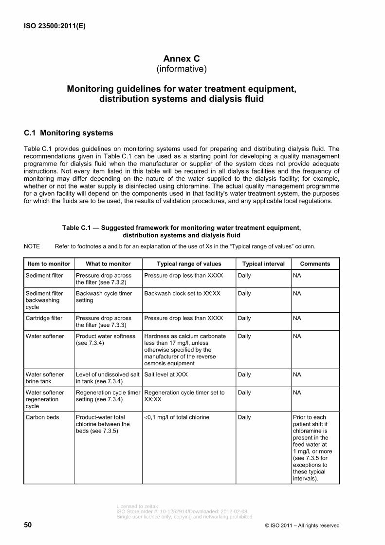
ISO 23500:2011(E)
50 © ISO 2011 – All rights reserved
Annex C (informative)
Monitoring guidelines for water treatment equipment,
distribution systems and dialysis fluid
C.1 Monitoring systems
Table C.1 provides guidelines on monitoring systems used for preparing and distributing dialysis fluid. The recommendations given in Table C.1 can be used as a starting point for developing a quality management programme for dialysis fluid when the manufacturer or supplier of the system does not provide adequate instructions. Not every item listed in this table will be required in all dialysis facilities and the frequency of monitoring may differ depending on the nature of the water supplied to the dialysis facility; for example, whether or not the water supply is disinfected using chloramine. The actual quality management programme for a given facility will depend on the components used in that facility's water treatment system, the purposes for which the fluids are to be used, the results of validation procedures, and any applicable local regulations.
Table C.1 — Suggested framework for monitoring water treatment equipment, distribution systems and dialysis fluid
NOTE Refer to footnotes a and b for an explanation of the use of Xs in the “Typical range of values” column.
Item to monitor What to monitor Typical range of values Typical interval Comments
Sediment filter Pressure drop across the filter (see 7.3.2)
Pressure drop less than XXXX Daily NA
Sediment filter backwashing cycle
Backwash cycle timer setting
Backwash clock set to XX:XX Daily NA
Cartridge filter Pressure drop across the filter (see 7.3.3)
Pressure drop less than XXXX Daily NA
Water softener Product water softness (see 7.3.4)
Hardness as calcium carbonate less than 17 mg/l, unless otherwise specified by the manufacturer of the reverse osmosis equipment
Daily NA
Water softener brine tank
Level of undissolved salt in tank (see 7.3.4)
Salt level at XXX Daily NA
Water softener regeneration cycle
Regeneration cycle timer setting (see 7.3.4)
Regeneration cycle timer set to XX:XX
Daily NA
Carbon beds Product-water total chlorine between the beds (see 7.3.5)
<0,1 mg/l of total chlorine Daily Prior to each patient shift if chloramine is present in the feed water at 1 mg/l, or more (see 7.3.5 for exceptions to these typical intervals).
Licensed to zeitakISO Store order #: 10-1252914/Downloaded: 2012-02-08Single user licence only, copying and networking prohibited
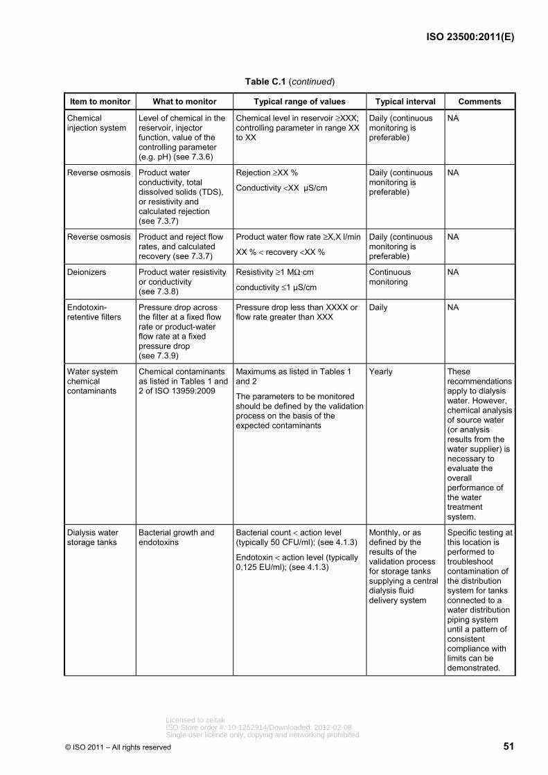
ISO 23500:2011(E)
© ISO 2011 – All rights reserved 51
Table C.1 (continued)
Item to monitor What to monitor Typical range of values Typical interval Comments
Chemical injection system
Level of chemical in the reservoir, injector function, value of the controlling parameter (e.g. pH) (see 7.3.6)
Chemical level in reservoir ≥XXX; controlling parameter in range XX to XX
Daily (continuous monitoring is preferable)
NA
Reverse osmosis Product water conductivity, total dissolved solids (TDS), or resistivity and calculated rejection (see 7.3.7)
Rejection ≥XX %
Conductivity <XX µS/cm
Daily (continuous monitoring is preferable)
NA
Reverse osmosis Product and reject flow rates, and calculated recovery (see 7.3.7)
Product water flow rate ≥X,X l/min
XX % < recovery <XX %
Daily (continuous monitoring is preferable)
NA
Deionizers Product water resistivity or conductivity (see 7.3.8)
Resistivity ≥1 MΩ·cm
conductivity ≤1 µS/cm
Continuous monitoring
NA
Endotoxin-retentive filters
Pressure drop across the filter at a fixed flow rate or product-water flow rate at a fixed pressure drop (see 7.3.9)
Pressure drop less than XXXX or flow rate greater than XXX
Daily NA
Water system chemical contaminants
Chemical contaminants as listed in Tables 1 and 2 of ISO 13959:2009
Maximums as listed in Tables 1 and 2
The parameters to be monitored should be defined by the validation process on the basis of the expected contaminants
Yearly These recommendations apply to dialysis water. However, chemical analysis of source water (or analysis results from the water supplier) is necessary to evaluate the overall performance of the water treatment system.
Dialysis water storage tanks
Bacterial growth and endotoxins
Bacterial count < action level (typically 50 CFU/ml); (see 4.1.3)
Endotoxin < action level (typically 0,125 EU/ml); (see 4.1.3)
Monthly, or as defined by the results of the validation process for storage tanks supplying a central dialysis fluid delivery system
Specific testing at this location is performed to troubleshoot contamination of the distribution system for tanks connected to a water distribution piping system until a pattern of consistent compliance with limits can be demonstrated.
Licensed to zeitakISO Store order #: 10-1252914/Downloaded: 2012-02-08Single user licence only, copying and networking prohibited
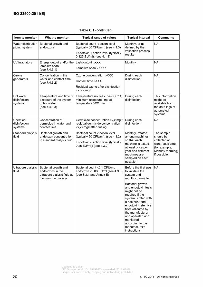
ISO 23500:2011(E)
52 © ISO 2011 – All rights reserved
Table C.1 (continued)
Item to monitor What to monitor Typical range of values Typical interval Comments
Water distribution piping system
Bacterial growth and endotoxins
Bacterial count < action level (typically 50 CFU/ml); (see 4.1.3)
Endotoxin < action level (typically 0,125 EU/ml); (see 4.1.3)
Monthly, or as defined by the validation process results
NA
UV irradiators Energy output and/or the lamp life span (see 7.4.3.1)
Light output >XXX
Lamp life span <XXXX
Monthly NA
Ozone generators
Concentration in the water and contact time (see 7.4.3.2)
Ozone concentration >XXX
Contact time >XXX
Residual ozone after disinfection <X,XX mg/l
During each disinfection
NA
Hot water disinfection systems
Temperature and time of exposure of the system to hot water (see 7.4.3.3)
Temperature not less than XX °C; minimum exposure time at temperature ≥XX min
During each disinfection
This information might be available from the data logs of automated systems.
Chemical disinfection systems
Concentration of germicide in water and contact time
Germicide concentration >x,x mg/l; residual germicide concentration <x,xx mg/l after rinsing
During each disinfection
NA
Standard dialysis fluid
Bacterial growth and endotoxin concentration in standard dialysis fluid
Bacterial count < action level (typically 50 CFU/ml); (see 4.3.2)
Endotoxin < action level (typically 0,25 EU/ml); (see 4.3.2)
Monthly, rotated among machines so that each machine is tested at least once per year and different machines are sampled on each occasion
The sample should be collected at worst-case time (for example, Monday morning) if possible.
Ultrapure dialysis fluid
Bacterial growth and endotoxins in the ultrapure dialysis fluid as it enters the dialyser
Bacterial count <0,1 CFU/ml; endotoxin <0,03 EU/ml (see 4.3.3) (see 8.3.1 and Annex E)
Before the first use to validate the system and monthly thereafter
Bacterial growth and endotoxin tests might not be required if the system is fitted with a bacteria- and endotoxin-retentive filter validated by the manufacturer and operated and monitored according to the manufacturer's instructions
NA
Licensed to zeitakISO Store order #: 10-1252914/Downloaded: 2012-02-08Single user licence only, copying and networking prohibited

ISO 23500:2011(E)
© ISO 2011 – All rights reserved 53
Table C.1 (continued)
Item to monitor What to monitor Typical range of values Typical interval Comments
Dialysis fluid Conductivity and pH XX,X mS/cm < conductivity <XX,X mS/cm
pH in the range 6,9 to 8,0 for bicarbonate dialysis fluid, or as otherwise specified by the manufacturer
Before each treatment, independent of the dialysis machine, if specified by the manufacturer (continuous monitoring for proportioning systems)
pH monitoring is necessary only if recommended by the dialysis machine manufacturer.
Substitution fluid Bacterial growth and endotoxins in the ultrapure dialysis fluid as it enters the dialyser
Sterile and nonpyrogenic (see 8.3.1 and Annex E)
Bacterial growth and endotoxin tests are not required if the system is fitted with a bacteria- and endotoxin-retentive filter validated by the manufacturer and operated and monitored according to the manufacturer's instructions
NA
a It is not possible to specify universally acceptable operating ranges for each device listed in the table, since some of the specifications will be system-specific. In those cases, the facility should define an acceptable operating range based on the manufacturer's instructions or measurements of system performance. b The actual interval for monitoring, testing, cleaning and/or disinfection should be based on the results of the validation process and ongoing trend analysis (see Clause 6 and 8.2.2).
Licensed to zeitakISO Store order #: 10-1252914/Downloaded: 2012-02-08Single user licence only, copying and networking prohibited
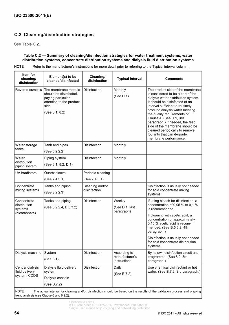
ISO 23500:2011(E)
54 © ISO 2011 – All rights reserved
C.2 Cleaning/disinfection strategies
See Table C.2.
Table C.2 — Summary of cleaning/disinfection strategies for water treatment systems, water distribution systems, concentrate distribution systems and dialysis fluid distribution systems
NOTE Refer to the manufacturer's instructions for more detail prior to referring to the Typical interval column.
Item for cleaning/
disinfection
Element(s) to be cleaned/disinfected
Cleaning/ disinfection Typical interval Comments
Reverse osmosis The membrane module should be disinfected, paying particular attention to the product side
(See 8.1, 8.2)
Disinfection Monthly
(See D.1)
The product side of the membrane is considered to be a part of the dialysis water distribution system. It should be disinfected at an interval sufficient to routinely produce dialysis water meeting the quality requirements of Clause 4. (See D.1, 3rd paragraph.) If needed, the feed side of the membrane should be cleaned periodically to remove foulants that can degrade membrane performance.
Water storage tanks
Tank and pipes
(See 8.2.2.2)
Disinfection Monthly
Water distribution piping system
Piping system
(See 8.1, 8.2, D.1)
Disinfection Monthly
UV irradiators Quartz sleeve
(See 7.4.3.1)
Periodic cleaning
(See 7.4.3.1)
Concentrate mixing systems
Tanks and piping
(See 8.2.2.3)
Cleaning and/or disinfection
Disinfection is usually not needed for acid concentrate mixing systems.
Concentrate distribution systems (bicarbonate)
Tanks and piping
(See 8.2.2.4, B.5.3.2)
Disinfection Weekly
(See D.1, last paragraph)
If using bleach for disinfection, a concentration of 0,05 % to 0,1 % is recommended.
If cleaning with acetic acid, a concentration of approximately 0,15 % acetic acid is recom-mended. (See B.5.3.2, 4th paragraph.)
Disinfection is usually not needed for acid concentrate distribution systems.
Dialysis machine System
(See 8.1)
Disinfection According to manufacturer's instructions
By its own disinfection circuit and programme. (See 8.2, 3rd paragraph.)
Central dialysis fluid delivery system, CDDS
Dialysis fluid delivery system
Dialysis console
(See B.7.2)
Disinfection Daily
(See B.7.2)
Use chemical disinfectant or hot water. (See B.7.2, 3rd paragraph.)
NOTE The actual interval for cleaning and/or disinfection should be based on the results of the validation process and ongoing trend analysis (see Clause 6 and 8.2.2).
Licensed to zeitakISO Store order #: 10-1252914/Downloaded: 2012-02-08Single user licence only, copying and networking prohibited
ISO 23500:2011(E)
© ISO 2011 – All rights reserved 55
Annex D (informative)
Strategies for microbiological control
D.1 General
The strategy for controlling the proliferation of microorganisms in haemodialysis systems primarily involves proper system design and operation, and regular disinfection of water treatment system and haemodialysis machines. A key concept in ensuring compliance with the requirements of 4.1.3 and 4.3 is that disinfection schedules should be designed to prevent bacterial proliferation, rather than being designed to eliminate bacteria once they have proliferated to an unacceptable level. With this strategy, monitoring levels of bacteria and endotoxins serves to demonstrate that the disinfection programme is effective, not to indicate when disinfection should be performed. Gram-negative water bacteria, their associated lipopolysaccharides (bacterial endotoxins), and nontuberculous mycobacteria (NTM) most frequently come from the community water supply, and levels of those bacteria can be amplified depending on the water treatment system, dialysis fluid distribution system, type of dialysis machine, and method of disinfection.
All components of dialysis water treatment and distribution systems, and dialysis fluid preparation and distribution systems, can serve as reservoirs of microbial contamination. Dialysis water distribution systems frequently use pipes that are of larger diameter and longer than are needed to handle the required flow. Oversized piping increases both the total fluid volume and the wetted surface area of the system. Gram-negative bacteria in fluids remaining in pipes overnight multiply rapidly and colonize the wet surfaces, thus producing bacterial populations and endotoxin quantities in proportion to the volume and surface area. Such colonization results in the formation of protective biofilm that is difficult to remove once formed and that provides a barrier between the bacteria and germicide during disinfection.
Biofilm is a community of microorganisms consisting of cells that are irreversibly attached to a surface or interface or to each other (Donlan and Costerton, 2002). Biofilms can occur at solid–liquid, solid–air and liquid–air interfaces. Most microorganisms can form biofilms and more than 99 % of all microorganisms live in such aggregates (Costerton, et al., 1987). A feature of all biofilms is that the organisms are embedded in a matrix of microbial origin, consisting of extracellular polymeric substances (EPS). The EPS comprises mainly polysaccharides and proteins, which form hydrogel matrices (Fleming, et al., 2010). The structure of biofilm, and the physiological attributes of biofilm organisms, confer an inherent resistance to antimicrobial agents, whether those agents are antibiotics, disinfectants or germicides.
Mechanisms responsible for resistance can include
⎯ delayed penetration of the antimicrobial agent through the biofilm matrix,
⎯ altered growth rate of biofilm organisms, and
⎯ other physiological changes related to the mode of growth of the biofilm.
A certain amount of biofilm formation is considered unavoidable in dialysis water systems. When the level of biofilm is such that the action levels for microorganisms and endotoxins in the dialysis water cannot be routinely achieved, the operation of the system is compromised from a medical and technical point of view. This level of biofilm formation is often referred to as biofouling. The key to avoiding biofouling is to minimize biofilm development. The extent of biofilm growth is dependent on the availability of nutrients. Classic biocidal approaches usually do not limit nutrient availability. In fact, some biocides increase nutrient availability by oxidizing recalcitrant organics and making them more bioavailable (Hammes, et al., 2007).
Routine disinfection should be performed to control bacterial contamination of distribution systems. The frequency of disinfection will vary with the design of the system and the extent to which biofilm has already formed in existing systems. Bleach and ozone are generally the most effective agents against biofilm, and
Licensed to zeitakISO Store order #: 10-1252914/Downloaded: 2012-02-08Single user licence only, copying and networking prohibited

ISO 23500:2011(E)
56 © ISO 2011 – All rights reserved
their use might be more efficacious if the pipes are treated first with a descaling agent. However, in some cases, complete or partial replacement of a distribution system might be the only way to reestablish control over mature biofilm.
It is commonly believed that maintaining flow through piping systems at all times minimizes biofilm formation. However, in many dialysis facilities there is no flow through distribution systems when the dialysis facility is not in operation, such as at night and on Sundays. Further, it has been demonstrated that microbial growth and biofilm formation in hydraulic systems cannot be controlled by the fluid velocity (Soini, et al., 2002). Data from the semiconductor industry show that a Reynolds number of 3 000 in a piping system is sufficient to prevent bacterial contamination in the water (Libman, 2006). A Reynolds number of approximately 3 000 is obtained with a flow velocity of 0,15 m/s in a 2 cm diameter pipe (0,5 ft/s in a 3/4” diameter pipe). However, even in systems operating with a Reynolds number of 3 000, biofilm was found on the internal surface of the pipes (Libman, 2006). Even if it were possible to specify a minimum flow velocity that was effective in reducing biofilm formation and bacterial contamination, use of such a minimum flow velocity would not provide a substitute for regular disinfection of the distribution system. Other measures can also help protect pipes from contamination. A mechanism should be incorporated in a distribution system to ensure that disinfectant does not drain from pipes during the disinfection period. Dead-end pipes and unused branches and taps that can trap fluid should be eliminated because they act as reservoirs of bacteria and are capable of continuously inoculating the entire volume of the system. Joints between sections of piping and between piping and fittings should be formed in a manner that minimizes the formation of crevices and other voids that might serve as sites for bacterial colonization. Pipes should not be cut with a hacksaw. Any burrs should be removed before the joint is formed. These measures also minimize the possibility that pockets of residual disinfectant could remain in the piping system after disinfection.
A storage tank in the dialysis water or dialysis fluid distribution system greatly increases the volume of fluid and surface area available and can serve as a niche for water bacteria. Storage tanks are therefore not recommended for use in dialysis water or dialysis fluid distribution systems unless they are frequently drained and adequately disinfected. It could be necessary for the user to scrub the sides of the tank to remove bacterial biofilm if the tank design and maintenance are not adequate to prevent bacterial proliferation. A bacteria- and endotoxin-retentive filter, distal to the storage tank, or some other form of bacterial control device, is recommended.
For most haemodialysis machines, routine disinfection with hot water or with a chemical germicide connected to a disinfection port on the machine does not disinfect the line between the outlet from the dialysis water distribution system and the back of the dialysis machine. Users should establish a procedure for regular disinfection of this line. One approach is to rinse the haemodialysis machines with water containing germicide or hot water when the dialysis water distribution loop is disinfected. If this procedure is used with a chemical germicide, each haemodialysis machine should be rinsed and tested for the absence of residual germicide following disinfection.
Storage times for bicarbonate concentrate should be minimized (normally less than 24 h), as well as the mixing of fresh bicarbonate concentrate with unused portions of concentrate from a previous batch. The manufacturer's instructions should be followed if they are available. Facilities that reuse concentrate containers for bicarbonate concentrate should disinfect the containers at least weekly. Bicarbonate concentrate can support prolific growth of microorganisms. Containers can be disinfected with household bleach solutions (300 mg/l to 600 mg/l free chlorine), with a contact time of about 30 min or according to another nationally approved standard or regulation, or according to the manufacturer's instructions. Following disinfection, the containers should be drained, rinsed, and inverted to dry.
D.2 Microbial monitoring methods
D.2.1 General
The microbial quality of dialysis water should be monitored regularly to validate the effectiveness of the disinfection programme. The frequency of monitoring should be determined during the process of system validation. In the absence of a formal determination of frequency, monitoring is usually performed monthly. Monitoring can be accomplished by direct plate counts, in conjunction with the measurement of bacterial endotoxins.
Licensed to zeitakISO Store order #: 10-1252914/Downloaded: 2012-02-08Single user licence only, copying and networking prohibited
ISO 23500:2011(E)
© ISO 2011 – All rights reserved 57
Samples of dialysis water should be collected from several places to give an indication of the microbial quality of the water throughout the dialysis water distribution system. For routine monitoring, samples should be collected from the last outlet of the dialysis water distribution loop, where dialysis water enters equipment used to reprocess dialysers, and where dialysis water enters equipment used to prepare bicarbonate concentrate or from the bicarbonate concentrate mixing tank. Additional testing, such as at the end of the water treatment cascade and at the outlet of the storage tank, if one is used, can be necessary during qualification of a newly installed system or when troubleshooting the cause of contamination within the dialysis water distribution loop. For central dialysis fluid distribution systems, samples should be collected from the last outlet of the dialysis fluid distribution loop.
For dialysis machines that are not fitted with validated endotoxin-retentive filters, dialysis fluid samples should be collected from enough machines so that each machine is tested at least once per year. For dialysis machines fitted with validated endotoxin-retentive filters, samples should be collected according to the filter manufacturer's instructions. If testing of any haemodialysis machine reveals a level of contamination above the action level, an investigation should be conducted. The investigation should be based on the presumption that other haemodialysis machines might also be contaminated. It should include a review of compliance with disinfection and sampling procedures and an evaluation of microbiological data for the previous three months to look for trends. The offending machine should be retested and an additional sample of machines tested to determine if the contamination was limited to a single machine or more widespread. The person in charge should also be notified.
Cultures should be repeated when bacterial counts exceed the allowable levels. If culture growth exceeds permissible standards, samples from the dialysis water distribution system or dialysis fluid distribution system and haemodialysis machines should be cultured weekly until acceptable results are obtained. Additional samples should be collected when there is a clinical indication of a pyrogenic reaction or septicaemia, and following a specific request by the clinician or the infection control practitioner.
Samples should always be collected before sanitization/disinfection or no sooner than 24 h after disinfection. For systems disinfected daily, samples should be collected before, and as close as practicable to, the next disinfection. Samples from haemodialysis machines should always be collected before disinfection. Culture dialysis water and dialysis fluid weekly for new systems until a pattern has been established. For established systems, culture monthly unless a greater frequency is dictated by historical data at a given institution. If biofouling is suspected, for example due to erratic microbiological test results, it could be necessary to check for the presence of biofilm (see D.2.3).
D.2.2 Sample collection
Samples should be collected directly from sampling ports situated in different parts of the dialysis water or dialysis fluid distribution system. In general, the sampling ports should be opened and the water or dialysis fluid should be allowed to run for at least 60 s before a sample is collected in a sterile, endotoxin-free container. Containers validated for collection of pyrogen samples should be used to collect samples. A minimum of 50 ml of water or dialysis fluid, or the volume specified by the laboratory performing the test, should be collected. Sampling ports should be disinfected using sterile gauze saturated with alcohol, or another solution validated for this purpose, to wipe the sampling port. The sample should be collected only when no disinfectant residual is present.
Dialysis fluid samples should be collected from a sampling port in the dialysis fluid inlet line to the dialyser, or from the dialysis fluid outlet port of the dialyser, or from a sampling port in the dialysis fluid outlet line of the dialyser. In some newer haemodialysis machines, dialysis fluid flow stops when the dialysis fluid lines are disconnected from the port. In these instances, the machines are equipped with dialysis fluid sampling ports that can be accessed using a syringe. Sampling ports may be disinfected with alcohol and allowed to air dry. A 30 ml sterile syringe should then be used to aspirate dialysis fluid out of and into the sampling port before filling the syringe. The filled syringe should be discarded, and a fresh sample of dialysis fluid should be collected using a new sterile syringe. At least 25 ml of fluid, or the volume specified by the laboratory performing the test, should be collected in sterile endotoxin-free specimen containers.
Licensed to zeitakISO Store order #: 10-1252914/Downloaded: 2012-02-08Single user licence only, copying and networking prohibited
ISO 23500:2011(E)
58 © ISO 2011 – All rights reserved
D.2.3 Heterotrophic plate count
Samples should be analysed as soon as possible after collection to avoid unpredictable changes in the microbial population. If samples cannot be analysed within 4 h of collection, they should be stored at <10 °C during transit to the laboratory. Sample storage for more than 24 h should be avoided. The reference method for culturing is the membrane filtration technique. With this method, a known volume of sample or diluted sample is filtered through a 0,45 µm membrane filter and the membrane filter is aseptically transferred to the surface of an agar plate. The spread plate technique may also be used. With this method, an inoculum of at least 0,2 ml of sample is spread equally over the surface of the agar plate. Use of a calibrated loop to apply the sample to the agar plate is NOT permitted. The pour plate technique may also be used. A sample volume of 1 ml is usually used with this method. Dip samplers should not be used. The culture medium should be tryptone glucose extract agar (TGEA), Reasoner's agar No. 2 (R2A), or another medium that can be demonstrated to provide equivalent results. Blood and chocolate agars should not be used. Plates should be incubated at 17 °C to 23 °C for 7 days. Other incubation times and temperatures may be used if it can be demonstrated that they provide equivalent results. During incubation, the plates should be sealed or kept in a plastic bag to avoid desiccation of the agar if that is a concern. Colonies should be counted using a magnifying device. If a more accurate count from plates containing fewer than 30 or more than 300 colonies is desired, larger or smaller volumes may be cultured. Smaller volumes can be obtained by making 1:10 serial dilutions in sterile phosphate buffer. If larger volumes are required, the membrane filtration method should generally be used.
It is virtually impossible to keep a dialysis water or dialysis fluid distribution system sterile; microorganisms will always be present on surfaces waiting for nutrients which, in the case of lithotrophic organisms, can even be inorganic (Flemming, 2002). Heterotrophic plate counts do not provide a good measure of the presence of biofilm. Fluid samples give no information about the site, extent or composition of a biofilm. Although biofilms contaminate the fluid in a distribution system, they do so only very irregularly. Erratic colony counts might indicate the presence of biofouling since clusters of cells might be sloughed from the biofilm with release of bacteria into the water or dialysis fluid. Currently, few practical methods are available for the routine detection of biofilm. Conventional methods rely on sampling-defined surface areas or on exposure of test surfaces (coupons) with subsequent analysis in the laboratory. A classic example is the so-called “Robbins device” (Kharazmi, et al., 1999), which consists of plugs inserted flush with pipe walls, thereby experiencing the same shear stress as the wall itself. After given periods of time, they are removed and analysed in the laboratory for all biofilm-relevant parameters. The disadvantage of such systems is the time-lag between analysis and result. Jacobs et al. (1996) described a simple spectrophotometric monitoring method, using a nucleotide-specific fluorescent stain (4′,6-diamidino-2-phenylindole) and automated measurement. Other methods which report biofilm growth online, non-destructively and in real time have been invented. They are all based on physical methods. If careful attention is paid to routine disinfection, routine monitoring for biofilm is not necessary. However, when the level of biofilm leads to a biofouling situation, it might be necessary to determine the level of biofilm in the system using the methods currently available.
D.2.4 Bacterial endotoxin test
Bacterial endotoxin testing is done using the Limulus amoebocyte lysate (LAL) assay. Two basic types of assay can be performed. The first is a kinetic assay, which is available in a colorimetric or turbidimetric format, and the second is a gel-clot assay.
The kinetic LAL assay uses control standard endotoxins to generate a standard curve to which unknowns are compared and concentrations are determined using linear regression. The kinetic assays employed in laboratories generally use a computer-driven spectrophotometer that automatically calculates the amount of endotoxins on the basis of colour development or onset times for gel formation.
The gel-clot LAL assay is not as sensitive as the kinetic assay and provides only a positive or negative result; that is, it shows if endotoxins are present, or not, at a particular concentration. Single tube gel-clot tubes are available from several commercial sources, and kits with the following sensitivities are available: 0,015 EU, 0,03 EU, 0,06 EU, 0,125 EU, 0,25 EU, and 0,5 EU. At a minimum, two tubes should be run each time the assay is performed. The first tube contains LAL reagent and the sample to be tested. The second tube contains LAL reagent, a known amount of endotoxins, and the sample to be tested. The second tube acts as a positive control to confirm the absence of any interference that might lead to a false negative result. Positive control tubes are available from the suppliers of commercial LAL assays.
Licensed to zeitakISO Store order #: 10-1252914/Downloaded: 2012-02-08Single user licence only, copying and networking prohibited
ISO 23500:2011(E)
© ISO 2011 – All rights reserved 59
Annex E (informative)
Validation
E.1 General and background
This annex provides background for Clauses 6 and 8 as well as Annex C.
The dialysis fluid and the substitution fluid used for online convective therapies are the result of an online process and are used immediately after their production. For this reason, the use of “batch control” techniques based on testing at fixed intervals is not the most effective way to ensure the required quality level is continuously reached. Periodic assessment of the chemical and microbial fluid quality might not identify a potential problem; for example, if that problem arose just after a test sample was collected.
Furthermore, compliance with the requirement that substitution fluid used for online convective therapies be sterile cannot be demonstrated by culturing, but has to be assured by the application of a validated and adequately monitored process.
The monitoring plan of the overall system (i.e. including the steps from the dialysis water production to the generation of the dialysis fluid and substitution fluid) must be based on the knowledge acquired with the Validation Plan for the specific dialysis water or dialysis fluid production system and the monitoring strategies applicable to the dialysis fluid production devices as validated by the manufacturer.
Moreover, when using a validated and monitored process for removal of bacteria and endotoxins at the dialysis machine, sampling of the substitution fluid is not needed. The presence in the system of parts and equipment (e.g. dialysis machine or endotoxin-retentive filters) that have already been validated by the manufacturer is sufficient to ensure fluid quality, provided those parts and equipment are operated in accordance with the manufacturer's instructions. Sampling of the dialysis water or dialysis fluid should be performed if required by the manufacturer of the validated process.
For these reasons, and under the above conditions, an effective monitoring strategy should be based on the direct sampling of the produced water and/or dialysis fluid, on monitoring of the process parameters as recommended by the manufacturer and defined by knowledge of the water treatment or dialysis fluid preparation system acquired during the validation phase.
E.2 Validation programme
E.2.1 General
The performance of the dialysis water or dialysis fluid production system should be verified to demonstrate that the system is “fit for purpose”. The validation procedure should provide documentary evidence that the process will consistently produce dialysis water, dialysis fluid, or substitution fluid meeting the quality requirements of ISO 13959 and/or ISO 11663.
E.2.2 Validation steps
As described in Clause 6, validation consists of the following:
⎯ Validation Plan;
⎯ Installation and Operational Qualification;
⎯ Performance Qualification;
⎯ revalidation through the data collected during routine monitoring. Licensed to zeitakISO Store order #: 10-1252914/Downloaded: 2012-02-08Single user licence only, copying and networking prohibited
ISO 23500:2011(E)
60 © ISO 2011 – All rights reserved
E.2.3 Validation Plan
The Validation Plan is the road map for successful validation and provides a complete picture of the dialysis facility's validation activities.
The Validation Plan defines and lists all necessary activities and documentation for
⎯ Installation and Operational Qualification,
⎯ Performance Qualification, and
⎯ revalidation.
The level of detail in the plan should reflect the risk, complexity and novelty of the system. The Validation Plan should define all responsibilities during validation and subsequent system operation.
E.2.4 Performance Qualification
As described in Clause 6, the aim of Performance Qualification is to establish that the system, as a whole, functions consistently to produce water and dialysis fluid of the required quality when operated in accordance with the defined procedures and with an incoming water supply of defined characteristics.
The prerequisites for Performance Qualification are as follows:
⎯ a demonstration that the plant has been installed in accordance with the design plans and following the manufacturer's procedures for installation (i.e. Installation Qualification);
⎯ a demonstration that the system performs all the required actions and can be operated in accordance with relevant technical manuals (i.e. Operational Qualification).
Performance Qualification includes periodic assessment of a set of physical, chemical and microbiological parameters to demonstrate that a consistent performance pattern can be achieved for the specific system design and performance requirements.
The sampling and testing pattern can be relaxed during the monitoring phase (normal operation) provided it can be demonstrated that the system consistently yields high quality results over an extended period and that continuously monitored parameters provide full surveillance of the system performance.
Under these assumptions, the following pattern for Performance Qualification can be adopted.
The first phase requires a full chemical and microbiological analysis of the dialysis water or microbiological analysis of the dialysis fluid, followed by regular microbiological analyses to demonstrate consistent quality in the interval between disinfections. During this period, all the information about the system behaviour should be collected and fine-tuning of the action levels performed.
In this phase, the testing frequency of the microbiological parameters is kept at a higher level to create a “trend analysis” and identify any deviations to ensure the patients' safety.
The achievement of at least three consecutive results, consistently below the action level, allows the start of the second phase where the final frequency of testing of microbiological parameters and the final frequency of disinfection are implemented. Sampling should be performed prior to disinfection or, alternatively, not sooner than 24 h after the disinfection process, to avoid false negative results and to demonstrate adequate system behaviour. Samples taken after disinfection are used to demonstrate the effectiveness of the disinfection procedure; they should be taken at least once after the first disinfection and following any significant deviations in the microbiological quality of the dialysis water or dialysis fluid.
Attainment of two consecutive results within the action level allows the successful completion of Performance Qualification and the start of routine monitoring operations.
Licensed to zeitakISO Store order #: 10-1252914/Downloaded: 2012-02-08Single user licence only, copying and networking prohibited
ISO 23500:2011(E)
© ISO 2011 – All rights reserved 61
E.3 Consequences for the monitoring strategy
As a result of the validation process for the water treatment or dialysis fluid preparation system, adequate maintenance and routine monitoring plans are established. Based on these regimes, system monitoring starts after Performance Qualification and ensures ongoing conformance to quality criteria regarding dialysis fluid and in-house produced concentrates.
Trend analysis through monitoring should be used as a source of advanced information on system performance, thus enabling a proactive approach to system maintenance with consequential operational and financial benefits.
Monitoring is achieved with online and offline measurements. With current technology, the majority of parameters have to be measured offline.
The online monitoring of suitable parameters (such as conductivity) provides immediate identification of deviations from normal operating conditions, offering the following advantages:
⎯ timely identification of potential problems in their early stage;
⎯ quick and easy diagnosis of the root causes (incoming water quality/technical malfunction);
⎯ implementation of necessary countermeasures;
⎯ triggering of specific offline measurements.
As mentioned above, a purely time-based offline sampling regime has inherent limitations for the monitoring of a continuous production process since deviations might occur during the sampling intervals.
Table C.1 lists possible monitoring parameters and related frequencies of measurement.
Licensed to zeitakISO Store order #: 10-1252914/Downloaded: 2012-02-08Single user licence only, copying and networking prohibited
ISO 23500:2011(E)
62 © ISO 2011 – All rights reserved
Annex F (informative)
Special considerations for home haemodialysis
F.1 General
The quality of dialysis water used to prepare concentrate and dialysis fluid is as important for home haemodialysis as it is for in-centre haemodialysis. This International Standard is written principally to address equipment used for in-centre haemodialysis. While many of the provisions of this International Standard are also applicable to home haemodialysis, the latter treatment might pose some special challenges not encountered with in-centre haemodialysis. Similarly, home haemodialysis might require some departures from the provisions of this guidance regarding dialysis fluid preparation. Because of a renewed interest in home haemodialysis and, in particular, the use of more frequent treatment schedules, this annex was included in this International Standard to address some of the concerns particular to the home haemodialysis setting. The recommendations included in this annex apply to water treatment systems assembled from individual components. Some of the recommendations in this annex might not apply to systems for home haemodialysis containing integrated water treatment equipment designed and validated to produce water and dialysis fluid of the quality required by ISO 13959 and ISO 11663. Validated systems require assurance that the system is being operated under the validated conditions. Also, the recommendations of this annex do not apply to sorbent-based dialysate regeneration systems, which are excluded from the scope of this International Standard.
Home haemodialysis differs from in-centre haemodialysis in that the patient or a helper will be responsible for day-to-day operation and maintenance of the water treatment and other dialysis equipment. In general, these individuals will not have formal technical training in haemodialysis. Therefore, the dialysis centre should provide training in the operation and maintenance of the equipment and require a demonstration of competence in those areas before home treatments are begun.
F.2 Fluid quality
Dialysis water, concentrate, and dialysis fluid used for home haemodialysis applications should meet the quality requirements set forth in Clause 3 of ISO 13959:2009, Clause 4 of ISO 13958:2009 and Clause 4 of ISO 11663:2009.
F.3 Utilities
To incorporate a haemodialysis machine in a home, the home will need a water supply, a drain connection, and a dedicated power source. It is recommended that the utility companies providing water and power to the patient's home be notified that home dialysis is being performed at that location and that restoring service after any interruption should be a priority.
F.3.1 Water supply
If the water is supplied by a municipal water system, it should meet the applicable standards for drinking water. Periodic evaluation of source water should be performed to confirm that it meets this International Standard.
If the water is not supplied by a municipal water system, for example, water obtained from a private well, applicable drinking water standards might not be met. Since the quality of such water might change over time, and since the water source might not be routinely monitored, the source water should be analysed at least yearly. More frequent analyses can be needed if the water source is subject to seasonal changes or contamination from sources such as septic tanks, underground fuel storage tanks, or agricultural waste and chemicals. These analyses might not need to include all the contaminants listed in Tables 1 and 2 of
Licensed to zeitakISO Store order #: 10-1252914/Downloaded: 2012-02-08Single user licence only, copying and networking prohibited

ISO 23500:2011(E)
© ISO 2011 – All rights reserved 63
ISO 13959:2009 if only certain contaminants are known to be of concern. If there is documented contamination of the water from any of the sources listed above, use of the water for home haemodialysis should be reconsidered. If the home also has a septic system, the source water should be monitored for contamination by fluids from the septic system. Water quality should also be analysed following a heavy rain or flood.
If a system is used that contains integrated water treatment equipment designed and validated to produce dialysis water and dialysis fluid of the quality required by ISO 13959 and ISO 11663, there should be periodic evaluation of the feed water to demonstrate that the quality of the feed water meets the requirements for that system or, if not, that there is adequate pretreatment.
The water supply should support the maximum demand of the water treatment components. The piping to a single-patient system should be at least 1 cm in diameter. The water pressure should meet the minimum requirements of the water treatment system, typically at least 20 psig (approximately 1,5 bar). Other components in the home that use water can temporarily reduce the water pressure if activated. These components include showers, toilets, clothes washers and dishwashers. A loss of water pressure could cause the RO system used for dialysis water treatment to shut down, thereby triggering the dialysis machine's low-water-pressure alarm. If fluctuations in water pressure become an issue, a bladder tank may be installed in the line supplying water to the water treatment system to allow the system to continue operation during periods of low water pressure. Homes with an individual well could need to increase the pressure setting of the well pump, increase the size of the pump, or install a booster pump to ensure adequate pressure.
Water temperature might be an issue, particularly during winter. The performance of an RO system is temperature dependent, with the product-water flow rate decreasing as the temperature decreases. Removal of chloramines by activated carbon is also temperature dependent, with the efficiency of removal decreasing as the temperature decreases. Finally, the treated water temperature needs to meet the minimum requirement for the dialysis machine, typically 10 °C. If the water temperature decreases below 10 °C, the heater in the dialysis machine might be unable to increase the temperature to the desired dialysate temperature (37 °C). A tempering valve could be needed to ensure a consistent supply of water of an adequate temperature. If a tempering valve is installed, it should meet the requirements of 4.2.3 of ISO 26722:2009 and the water heater should be capable of delivering the amount of hot water needed to provide water of the desired temperature for the duration of the dialysis treatment. Alternatively, the demand for treated water may be reduced during periods of reduced water temperature by decreasing the dialysis fluid flow rate.
Backflow protection should be installed before the start of the water treatment system in compliance with any requirements of the local plumbing code. These devices should be inspected at the frequency specified by the local plumbing code.
F.3.2 Drain
The drain should be capable of supporting the maximum flow from the dialysis machine, RO system, and any water pretreatment equipment. Typically, a 2,5 cm or larger diameter drain pipe is needed. The drain should incorporate some means of protecting against back siphon, such as an air break in the wastewater stream, to avoid backflow from the drain system into the haemodialysis machine or any water treatment component with a drain line. If the home has a septic tank, the septic tank should be able to process the volume of water from this drain. It might not be possible to perform nocturnal haemodialysis in a home with a septic tank since this tank might not be able to support the volume of water delivered to it over an extended period (8 h). Another potential limitation is that the septic system will be exposed to disinfectant chemicals (bleach, peracetic acid, hydrogen peroxide, etc.), which could kill the bacteria needed for the septic system to function.
F.3.3 Power
The power source used for the haemodialysis equipment should comply with the requirements of IEC 60601-2-16. Careful consideration should be given before connecting other electrical devices such as electric heaters, televisions, VCR/DVD players, or computers into the same circuit that supplies the dialysis machine or water treatment system. Extension cords should not be used to provide power to the dialysis machine or water treatment equipment, unless approved by the manufacturer of the dialysis machine or water treatment system for use with their equipment.
Licensed to zeitakISO Store order #: 10-1252914/Downloaded: 2012-02-08Single user licence only, copying and networking prohibited
ISO 23500:2011(E)
64 © ISO 2011 – All rights reserved
F.4 Environment
Haemodialysis involves large volumes of water and waste dialysate. Loose tubing connections or equipment malfunction might produce leaks that can cause damage to the home. If water treatment or dialysis equipment is located on an upper floor, leaking fluids might seep through the floor and damage ceilings on lower levels. It is recommended that areas where water is treated for dialysis, and in which dialysis is performed, be designed to contain fluid spills when they occur. The flooring material should be water resistant and capable of being easily cleaned. Carpeting or wooden floors are not recommended. In addition to being difficult to clean, carpet can mask blood spills in the dialysis area.
Home haemodialysis generally requires an area for storage of supplies, including dialysis concentrate. That area should provide a year-round environment that meets the manufacturer's recommendations for storage of the supplies.
F.5 Equipment
F.5.1 General
The equipment selected for home haemodialysis should be simple to operate. The patient/helpers in the home should be formally trained in the proper operation and maintenance of the haemodialysis and supporting water treatment equipment by the dialysis centre or its designee.
The final configuration of the water treatment system will depend on the quality of the feed water. As with in-centre dialysis, the water treatment system should be designed to produce dialysis water of the quality set forth in Clause 3 of ISO 13959:2009, when supplied with water containing contaminants at the highest anticipated level. Water treatment equipment may include sediment filters, softeners, carbon beds, reverse osmosis (RO) system, or deionizers (DI). Depending on the contaminants in the water, additional water treatment equipment may include iron filters, dealkalinizers, and nitrate filters. Unless specified otherwise in ISO 26722 or in this International Standard, water treatment equipment for home haemodialysis should meet the requirements of ISO 26722.
F.5.2 Softener
A water softener could be needed to prevent calcium and magnesium from forming scale on the membranes of a reverse osmosis system. For water with a high level of hardness, removal of calcium and magnesium with a softener can be necessary if the reverse osmosis system is to produce dialysis water that meets the requirements of ISO 13959 for calcium and magnesium. A softener typically is not needed to support a deionization system.
Softeners must be regenerated or exchanged on a regular basis. Only sodium chloride should be used to regenerate a softener. Potassium chloride should not be used for softener regeneration. Also, salt designated as rock salt should not be used for regeneration since it is not refined and typically contains sediments and other impurities that might damage O-rings and pistons and clog orifices in the softener control head. Single tank softeners can be set to regenerate automatically on set days or after they have processed a designated amount of water; alternatively, regeneration can be initiated manually. Softeners used for haemodialysis applications that regenerate automatically are fitted with a mechanism to prevent water from entering the product line during regeneration. Typically the timer on the softener is not interlocked to stop the reverse osmosis system when regeneration occurs. If the dialysis machine is producing dialysis fluid at that time, a low water pressure alarm will occur. For that reason, attention must be paid to setting the time for softener regeneration, particularly when daily nocturnal haemodialysis is being performed.
F.5.3 Carbon media
At least one carbon bed or filter should be installed even if the water supply is from a well and no chlorine is present. In addition to chlorine, carbon can remove organic contaminants from ground water, including solvents, pesticides, industrial wastes, and substances leaking from underground storage tanks. When water is obtained from a municipal water supply containing 1 mg/l or more of chloramine, two carbon beds
Licensed to zeitakISO Store order #: 10-1252914/Downloaded: 2012-02-08Single user licence only, copying and networking prohibited
ISO 23500:2011(E)
© ISO 2011 – All rights reserved 65
connected in series and providing the equivalent of an empty bed contact time of 10 min, or some other process incorporating safety redundancy for chloramine removal, is recommended. A means should be provided to sample the water between the primary chloramine removal process and the secondary removal process. If chlorine is not present in the water, the carbon should be changed on a routine schedule. If a means of chloramine removal, other than two series-connected carbon beds with 10 min of total empty bed contact time, is used then the system should be flushed for a sufficient period of time to ensure that water sampled is representative of the water to be used for treatment. Sufficient flushing is necessary to ensure that sampled water has not been resident in the removal system between treatments, such that it would under-represent the chloramine level that would be delivered during normal operation. In this case, the minimum flush time should be determined by the manufacturer of the equipment.
F.5.4 Reverse osmosis
Since the product flow rate will decrease with decreasing water temperature, a reverse osmosis system installed without a tempering valve to ensure constant feed-water temperature needs to be sized so that it will deliver the quantity of water required by the dialysis machine with the coldest anticipated water temperature.
F.5.5 Deionization
Deionization systems for home haemodialysis should have a means of preventing product water from reaching the point of use if the resistivity of the water is 1 MΩ·cm or less).
F.5.6 Dialysis water distribution
For home haemodialysis, a direct feed system will typically be used to distribute dialysis water to its points of use. The water-contacting surfaces of the distribution system should not be constructed of materials containing aluminium, copper, lead or zinc. Because systems used for home haemodialysis operate intermittently, the distribution system should be designed and maintained to minimize bacterial proliferation. The reverse osmosis system should be disinfected according to the manufacturer's instructions. The dialysis machine should be disinfected following each treatment according to the manufacturer's instructions. Because the line supplying water to the dialysis machine is not disinfected when the machine is disinfected, this line should be disinfected when the reverse osmosis system is disinfected and consideration should be given to replacing this line on a regular basis, such as yearly. Opaque tubing is preferred for this line to reduce the likelihood of algae growth; however, the tubing must be approved by the manufacturer of the dialysis machine. Consideration should also be given to installing an endotoxin- and bacteria-retentive filter in the dialysis machine, if the machine allows that option. If installed, this filter should be maintained and replaced according to the manufacturer's instructions.
F.6 Concentrate
F.6.1 Bicarbonate concentrate
Excess bicarbonate concentrate should be discarded after each treatment. Reusable bicarbonate containers should be disinfected, rinsed with treated water and inverted to dry after each treatment. Pick-up tubes should be rinsed with treated water and allowed to air dry after each treatment. If the bicarbonate solution is prepared from a powder, the patient/helpers should be trained to prepare the solution according to the proper procedure.
F.6.2 Acid concentrate
The patient/helpers should be trained to know that different haemodialysis machines use different proportioning ratios for concentrate and water and that they should ensure use of the correct acid concentrate for their haemodialysis machine. The acid concentrate used should be documented as part of the treatment record.
Licensed to zeitakISO Store order #: 10-1252914/Downloaded: 2012-02-08Single user licence only, copying and networking prohibited
ISO 23500:2011(E)
66 © ISO 2011 – All rights reserved
F.7 Monitoring
F.7.1 Water and dialysis fluid quality
The chemical quality of the dialysis water should be analysed at least once a year to ensure that it meets the requirements of ISO 13959. More frequent analysis could be needed if there are seasonal variations in source water quality or if the source water is supplied from a well. When any repairs are made to water treatment equipment, the impact on water quality should be evaluated and a chemical analysis performed if indicated. Chemical testing might not be required when replacing consumable components, such as filters or other components defined by the manufacturer as requiring regular replacement under normal use. Chemical testing might not be required when an entire water purification device is replaced with an equivalent device which has been validated by the manufacturer according to an equivalent performance specification as the device being replaced.
The microbiological quality of the dialysis fluid should be analysed using cultures and endotoxin measurements. If the dialysis fluid meets the recommendations of ISO 11663, then the dialysis water feeding the dialysis machine, and the bicarbonate concentrate, can be assumed to meet the appropriate requirements. Sampling for microbiological testing should be performed before disinfecting the water treatment system and dialysis machine. To avoid disconnecting hoses, and opening the system to possible contamination, the system should be designed with the necessary sampling ports. To obtain meaningful results, a system should be established to ensure proper collection of the samples and their timely submission to the testing laboratory.
As part of their training for home haemodialysis, patients/helpers should be instructed in any sample collection or water and dialysis fluid quality tests that they will be expected to perform in their homes. If the sample is collected by someone other than the patient/helper, that person should also be trained in the correct procedures for sample collection and testing.
F.7.2 Equipment
F.7.2.1 General
A log sheet should be provided by the dialysis facility and used to record all measures of water treatment system performance required by the equipment manufacturer or the dialysis facility. Measurements should be made at least 15 min after the water treatment system has been set in operation and before dialysis is initiated.
If any measure of water treatment system performance is found to be outside its acceptable range, the dialysis centre should be notified.
F.7.2.2 Cartridge filter
Monitoring the pressure drop (∆P) across a sediment filter may be used in the home environment to determine when the sediment filter has increased resistance of flow. Systems for use in the home environment which are capable of detecting reduced flow conditions through a sediment filter by alternative methods (such as with flow monitoring or insufficient feed-water detection) should also be considered acceptable for determination of sediment filter replacement.
F.7.2.3 Softener
The water hardness should be monitored prior to each treatment, using a sample obtained through a labelled sample port located between the softener and the reverse osmosis membranes or from the reject line from the reverse osmosis system. For hardness tests requiring colour differentiation, the person performing the analysis should be able to distinguish between the colour outputs of the test criteria. If the person cannot differentiate these colours, an automated meter should be used.
Licensed to zeitakISO Store order #: 10-1252914/Downloaded: 2012-02-08Single user licence only, copying and networking prohibited

ISO 23500:2011(E)
© ISO 2011 – All rights reserved 67
F.7.2.4 Carbon media
When the source water contains chloramine at a concentration of 1 mg/l, or more, the total chlorine concentration should be checked prior to each treatment. The patient/helper should be trained how to perform the total chlorine analysis, and should be trained regarding what action to take if total chlorine is detected above the specified limit. Depending on the test used, the patient/helper should be capable of distinguishing between different shades of pink or a digital meter should be used to indicate the total chlorine concentration.
F.7.2.5 Reverse osmosis
Prior to each treatment, the performance of the reverse osmosis system should be monitored by checking the product-water conductivity and percent rejection.
Licensed to zeitakISO Store order #: 10-1252914/Downloaded: 2012-02-08Single user licence only, copying and networking prohibited
ISO 23500:2011(E)
68 © ISO 2011 – All rights reserved
Annex G (informative)
Special considerations for acute haemodialysis
G.1 General
The items included within this annex are equipment used to treat water for the preparation of concentrates and dialysis fluid in the acute (hospital) setting. This annex deals with portable water treatment systems intended for use with a dialysis delivery system to deliver dialytic therapies at the bedside. This annex excludes equipment used in central systems that supply three or more points of use in an “acute dialysis” room. These systems are considered “central” water systems and thus are covered by the general guidance of this International Standard. Equipment used for a single patient in a home or nursing home setting is excluded from this annex because it falls within the scope of Annex F.
Single patients are treated in an acute hospital setting where dialysis equipment is taken to the patient's bedside. Acute dialysis patients might have increased susceptibility to adverse reactions due to their co-morbid conditions. The appearance of easy rolling “acute” carts that hold the portable water treatment system and dialysis machine, along with technological advancements, has attenuated many of the reasons given in the past for relaxing safety design standards established for equipment used in central water treatment systems when that equipment is used for acute dialysis. Therefore, the recommendations outlined in this International Standard are generally applicable in the acute setting, with the addition of the guidance provided in this annex. When less rigorous design standards are allowed, however, the onus is on the user to ensure appropriate water quality through increased monitoring and maintenance of the water treatment system.
G.2 Fluid quality
Water and concentrate used to prepare dialysis fluid for acute haemodialysis should meet the quality requirements set forth in Clause 3 of ISO 13959:2009 and Clause 4 of ISO 13958:2009, respectively. Dialysis fluid prepared from dialysis water and concentrate for use in acute haemodialysis should meet the quality requirements set forth in Clause 4 of ISO 11663:2009. Monitoring to demonstrate ongoing compliance with the chemical quality requirements of Clause 3 of ISO 13959:2009 should be performed as described in Clause 7 and G.3, with the exception that, in general, monitoring is not necessary on days when the equipment is not in operation. Compliance with the microbiological quality requirements of Clause 3 of ISO 13959:2009 and Clause 4 of ISO 11663:2009 requires regular and frequent disinfection of the equipment coupled with testing to demonstrate compliance with those requirements. If the test results fail to show compliance with the requirements, steps should be taken to change the frequency and/or procedure of disinfection and testing until compliance can be demonstrated. Because patients in the acute setting are likely to be more susceptible to microbiological contaminants in the dialysate, there could be benefit in using ultrapure dialysis fluid. One means of achieving ultrapure dialysis fluid is to pass the standard dialysis fluid through a bacteria- and endotoxin-retentive filter.
G.3 Equipment
G.3.1 General
This subclause contains recommendations for water treatment equipment specific to the acute haemodialysis setting. The general requirements and recommendations for equipment used to treat water for haemodialysis applications contained in ISO 13959 and ISO 26722 apply, unless otherwise noted in this annex.
The installer and user of acute haemodialysis water treatment systems are responsible for assuring that the water produced by the system can meet the maximum allowable chemical and microbiological contaminant levels specified in Clause 3 of ISO 13959:2009, or the prescription of the physician at installation. Beyond this qualification, it becomes the responsibility of the physician in charge of acute dialysis or his/her representative
Licensed to zeitakISO Store order #: 10-1252914/Downloaded: 2012-02-08Single user licence only, copying and networking prohibited

ISO 23500:2011(E)
© ISO 2011 – All rights reserved 69
to monitor the system to assure that the treatment device or devices maintain a level of water quality that meets the requirements of Clause 3 of ISO 13959:2009. Consideration should be given to seasonal or worse-case water quality when selecting portable water treatment systems. The use of pretreatment to remove contaminants that might impair the performance of the portable reverse osmosis (RO) or deionization (DI) system is recommended.
Any maintenance procedure related to the water treatment equipment, such as exchange of exhausted components, should be performed when no patient is connected to the dialysis delivery system.
G.3.2 Backflow prevention
Unlike central water systems in free-standing dialysis clinics, acute water systems in most cases connect directly to potable water systems. Though it is very unlikely that a portable (acute) water treatment system would back up and contaminate the potable water system, backflow prevention is considered a necessary and safe precaution for these systems. A backflow prevention device, such as a Pressure Principle Backflow Assembly (PPBA) or a vacuum breaker, should be installed at the point of connection to the potable water system. In some instances, a local code could require a “break tank” device in place of a PPBA as the preferred method to prevent backflow. Portable water treatment system designers should consider possible pressure drops and their effects on downstream components when sizing such devices. Backflow prevention devices should be tested and maintained per local plumbing codes.
Spent dialysis fluid and reject water from a reverse osmosis system unit should be discharged to drain in a manner that minimizes the potential for contamination of the patient-care area and the dialysis machine. An appropriate floor drain or standpipe connected to a sink drain should be utilized for this purpose. If such a drain is not available, spent dialysis fluid and reverse osmosis reject water may be discharged into a sink. In that circumstance, the sink should not be used for other purposes during dialysis and care should be taken to properly clean the sink after the treatment. In all cases, there should be an air gap at the point of discharge to prevent backflow into the dialysis machine.
G.3.3 Electrical safety
The power source used for the haemodialysis equipment should comply with the requirements of IEC 60601-2-16. For 110 V, 15 A power supplies, separate power sources should be used for the dialysis machine and the water treatment system in accordance with the manufacturer's requirements. Extension cords should not be used to provide power to the dialysis machine or water treatment equipment, unless they are approved by the manufacturer of the dialysis machine or water treatment system for use with their equipment and unless they comply with the facility's policies and procedures for the use of extension cords. Portable water treatment systems should comply with applicable electrical safety standards regarding electrostatic discharge (ESD), electromagnetic compatibility (EMC), and any other electrical safety standards as outlined in IEC 60601-1. It is critically important that electrical noise and current leakage be minimized in both the critical care and general bedside settings. These environments are likely to have life-sustaining equipment, such as ventilators, for which loss of function because of electrical interference could evoke a medical emergency. An electrical safety check should be performed at least once per year. An electrical safety check should also be performed following repairs that involve the power supply system, including repairs to power cords and cord caps. Portable water treatment system component enclosures should possess a level of water resistance equal to IEC 60529 IPX 1. Continued monitoring of the water system is necessary to maintain treatment methods consistent with safety.
G.3.4 Carbon media
Patients in the acute setting might be less capable of coping with premature chlorine/chloramine breakthrough than stable patients being treated in an outpatient facility because of their co-morbid conditions. Where practical, when the municipal water contains chloramine at a concentration of 1 mg/l, or more, portable water treatment systems should include two carbon beds in series, which together provide a minimum of 10 min Empty Bed Contact Time (EBCT). Historically, the requirement for two carbon beds in series was waived for portable dialysis systems because of the impracticality of providing these features while retaining the portability of the system. However, alternative technologies are now available that allow portability while retaining the redundancy associated with two carbon beds in series. Some portable reverse osmosis systems employ one granular activated carbon (GAC) tank followed by a dense carbon block as a polisher. Alternatively, experience suggests that two carbon block filters in series rated according to the NSF for a
Licensed to zeitakISO Store order #: 10-1252914/Downloaded: 2012-02-08Single user licence only, copying and networking prohibited
ISO 23500:2011(E)
70 © ISO 2011 – All rights reserved
minimum chlorine reduction capacity of 40 000 gal (approximately 150 000 litres) at a flow rate of 2 gal/min (7,7 l/min) and an incoming free chlorine concentration of 2 mg/l can be used. When used, carbon block filters should be intended for chloramine removal. Block carbon filters used in this application should not compromise the feed-water requirements specified by the manufacturer of the reverse osmosis system. Testing to demonstrate that the level of total chlorine is less than 0.1 mg/l should be performed before each treatment using a sample obtained from a port located between the two beds or filters. The equipment should be allowed to operate for at least 15 min before the test sample is drawn. For prolonged treatments, such as sustained low-efficiency dialysis (SLED), testing may be performed approximately every 8 h providing the EBCT of the carbon media is based on a dialysate flow rate of at least 500 ml/min and the actual dialysate flow rate is not more than 300 ml/min. Where it is not possible to provide the equivalent of a 10 min EBCT with carbon, practical alternatives include the addition of ascorbic acid to the acid concentrate or more frequent monitoring of the product water during the dialysis treatment.
Acute dialysis programmes should determine if the potable water supplied by the hospital or other water supplier contains secondary disinfectants and request that they be notified in advance of the use of secondary disinfectants, to ensure that their impact on water quality and patient safety can be evaluated. An example of a secondary disinfection would be the installation of a chlorine-dioxide-generating system. In the event that chlorine dioxide is present in the potable water, and in the absence of data regarding the haemolytic potential of chlorine dioxide, it is suggested that, in the interim, chlorine dioxide levels be measured using a commercially available test kit and that the maximum acceptable chlorine dioxide level be set at 0,1 mg/l.
G.3.5 Ion exchange
G.3.5.1 Deionization
When deionization is the primary method of water treatment, two portable mixed-bed DI tanks in a worker-polisher configuration are recommended. Alternatively, a cation tank and an anion tank, followed by a mixed-bed tank, can be installed. A DI polishing cartridge may also be used following a portable RO when the source water chemistry is such that the portable RO, on its own, will not produce water meeting the quality requirements of Clause 3 of ISO 13959:2009. Deionization systems for acute haemodialysis should have a mechanism to prevent product water from reaching the point of use if the specific resistivity of the water is 1 MΩ·cm or less. DI should be followed by an ultrafilter or other bacteria- and endotoxin-reducing device to remove microbiological contaminants that originate in the deionizer resin bed.
G.3.5.2 Softeners
Unless otherwise specified by the manufacturer of the reverse osmosis system, water treatment systems presented with incoming water with a hardness of >10 GPG (equivalent to 170 ppm of calcium carbonate or 10 °dH) should have a softener or other means of preventing scale formation. At lower levels of hardness (<10 GPG), the user may forgo the use of a softener by increasing the frequency of membrane descaling (acid cleaning) or by periodically replacing the reverse osmosis membranes in accordance with the instructions of the manufacturer of the reverse osmosis system. The amount of hardness in the source water and the volume of water used will determine the frequency of membrane cleaning and/or membrane replacement. To minimize space and weight requirements, softeners used in portable systems should not be equipped with a brine tank. Instead, a separate regeneration station with a brine tank and water source should be used for regenerating softeners.
Unlike central water treatment systems, regeneration devices, such as softeners, used in portable (acute) water treatment systems do not include a means to prevent product water from reaching the reverse osmosis system during regeneration. A portable water treatment system should not be operated without all its pretreatment devices online. In hospital settings where there is central softening of the potable water supply, hospital maintenance/plant staff should be made aware of the potential impact of hard water on reverse osmosis performance and the potential hazard to haemodialysis patients of untimely regeneration.
G.3.6 Reverse osmosis
A reverse osmosis system should demonstrate delivery of water meeting the quality requirements of Clause 3 of ISO 13959:2009; otherwise, additional treatment devices should be employed. The user may define monitoring in terms of percent rejection and product-water conductivity (RO). Compliance with both monitored parameters is required, since an increase in feed-water contaminants might result in product water unsuitable
Licensed to zeitakISO Store order #: 10-1252914/Downloaded: 2012-02-08Single user licence only, copying and networking prohibited
ISO 23500:2011(E)
© ISO 2011 – All rights reserved 71
for haemodialysis applications, even though the percent rejection of the membrane modules remains high. In this scenario, an additional water purification device should be installed after the reverse osmosis system to meet the standard. An example of such a device would be a deionizer polishing cartridge. The user should establish alarm limits for rejection and product-water conductivity or total dissolved solids (TDS) specific to the acute site.
Because reverse osmosis membranes tend to fail gradually, the risk is different from exhaustion of a deionizer where very high levels of contaminants, such as fluoride, might occur abruptly in the product water. It is recommended that reverse osmosis systems used in an acute dialysis setting incorporate a means of preventing the product water from reaching the patient in the event of a product-water conductivity or rejection rate alarm. Means of preventing product water from reaching the patient could include an automated divert to drain valve, reverse osmosis shutdown, or an immediate response by the operator to an alarm.
G.3.7 Endotoxin-retentive filters
It has been argued that the use of endotoxin-retentive filters in a water treatment system for acute dialysis using reverse osmosis is redundant, given that such systems are operated in a direct-feed configuration. Endotoxin-retentive filters should be installed after the deionizer tanks in systems using deionization. Even with reverse osmosis, it can be difficult to maintain portable water treatment equipment and the associated dialysis machine free of microbiological contamination because the equipment is often used intermittently and is subject to frequent connection and disconnection. For these reasons, in-line dialysis fluid filters are recommended as a final barrier against contamination of the dialysis fluid.
G.4 Microbial control strategies
Control of microbial contamination is the single most difficult aspect of maintaining portable equipment in compliance with the requirements of ISO 11663. Because of the non-routine nature of acute dialysis, systems used for acute haemodialysis operate intermittently and can be frequently connected and disconnected; they should be designed and maintained to minimize bacterial proliferation. There should be a continuous quality assessment performance improvement programme for monitoring the performance and maintenance of systems used for acute dialysis. The reverse osmosis system should be disinfected according to the manufacturer's instructions, and more frequently if the equipment is not operated for several days or if test results demonstrate that the disinfection schedule is inadequate to ensure compliance with the microbiological quality requirements of 4.1 of ISO 11663:2009. The potential for bacterial proliferation can be diminished by operating the equipment for at least 15 min each day, regardless of whether or not a treatment is being performed. Another approach would be to add a bacteriostatic agent (e.g. sodium bisulfite) to reverse osmosis systems that are to be stored. If a bacteriostatic agent is used, the machine should be clearly labelled to indicate the presence of that agent. Because of the potential for bacterial growth in carbon media, the manufacturer's instructions for scheduled replacement of carbon media should be followed, even though the product water might still meet the requirements for total chlorine. In the absence of a manufacturer's recommendation, carbon media should be replaced at least every six months. Provided that there is a continuous flow of dialysis fluid through the machine, dialysis machines that are used to perform multiple treatments during the day should be cleaned following each treatment and disinfected at the end of the day according to the manufacturer's instructions. If there is no dialysis fluid flow for more than 4 h between treatments, the machine should be disinfected before a second treatment is performed. If the machine is not disinfected daily, it should be disinfected before it is used. Because the line supplying water to the dialysis machine is not disinfected when the machine is disinfected, this line should be disinfected when the reverse osmosis system is disinfected and consideration should be given to replacing this line on a regular basis, such as yearly. Opaque tubing is preferred for this line to reduce the likelihood of algae growth; however, the tubing must be approved by the manufacturer of the dialysis machine. If individual containers of bicarbonate concentrate are used, pick-up tubes should be disinfected at the end of each treatment day as described in 8.2.2.4. If reusable containers are used for bicarbonate concentrate, they should also be disinfected at least weekly as described in 8.2.2.4. Consideration should be given to installing an in-line dialysis fluid filter in the dialysis machine, if the machine manufacturer allows that option. If installed, the dialysis fluid filter should be maintained and replaced according to the manufacturer's instructions.
Licensed to zeitakISO Store order #: 10-1252914/Downloaded: 2012-02-08Single user licence only, copying and networking prohibited
ISO 23500:2011(E)
72 © ISO 2011 – All rights reserved
Bibliography
Chemical contaminants with known toxicity to dialysis patients
Aluminium
[1] ALFREY, AC, LEGENDRE, GR, KAEHNY, WD. The dialysis encephalopathy syndrome. Possible aluminum intoxication. N Engl J Med 294:184-188, 1976
[2] KOVALCHIK, MT, KAEHNY, WD, HEGG, AP, JACKSON, JT, ALFREY, AC. Aluminum kinetics during haemodialysis. J Lab Clin Med 92:712-720, 1978
[3] WARD, MK, FEEST, TG, ELLIS, HA, PARKINSON, IS, KERR, DNS. Osteomalacic dialysis osteodystrophy: Evidence for a water-borne aetiological agent, probably aluminium. Lancet 1:841-845, 1978
[4] PARKINSON, IS, WARD, MK, KERR, DNS. Dialysis encephalopathy, bone disease and anaemia: The aluminium intoxication syndrome during regular haemodialysis. J Clin Pathol 34:1285-1294, 1981
[5] HODGE, KC, DAY, JP, O'HARA, M, ACKRILL, P, RALSTON, AJ. Critical concentrations of aluminium in water used for dialysis. Lancet 2: 802-803, 1981
[6] MASUYAMA, J, TACHIBANA, Y. Effects of water purification on renal osteodystrophy in the patients with regular hemodialysis therapy. J Japan Soc Kidney Dis 26:407-416, 1984
[7] KAISER, L, SCHWARTZ, KA. Aluminum-induced anemia. Am J Kidney Dis 6:348-352, 1985
[8] ALFREY, AC. Aluminum toxicity in patients with chronic renal failure. Ther Drug Monit 15:593-597, 1993
[9] RAHMAN, H, CHANNON, SM, PARKINSON, IS, SKILLEN, AW, WARD, MK, KERR, DNS. Aluminum in the dialysis fluid. Clin Nephrol 24[Suppl 1]:S78-S83, 1985
[10] DAVISON, AM, WALKER, GS, OLI, H, LEWINS, AM. Water supply aluminium concentration, dialysis dementia, and effect of reverse-osmosis water treatment. Lancet 2:785-787, 1982
[11] BUREN, DR, OLSEN, SM, BLAND, LA, ARDUINO, MJ, REID, MH, JARVIS, WR. Epidemic aluminum intoxication in hemodialysis patients traced to use of an aluminum pump. Kidney Int 48:469-474, 1995
[12] STUMM, W, MORGAN, JJ. Aquatic Chemistry: Chemical Equilibria and Rates in Natural Waters (3rd ed). New York: John Wiley & Sons, 1996, pp 272-275
[13] FERNÁNDEZ-MARTÍN, JL, CANTEROS, A, ALLES, A, MASSARI, P, CANNATA-ANDÍA, J. Aluminum exposure in chronic renal failure in Iberoamerica at the end of the 1990s: overview and perspectives. Am J Med Sci 320: 96-99, 2000.
[14] CANNATA-ANDÍA, JB. Reconsidering the importance of long-term low-level aluminum exposure in renal failure patients. Semin Dial 14: 5-7, 2001
[15] BEREND, K, VAN DER VOET, G, BOER, WH. Acute aluminum encephalopathy in a dialysis center caused by a cement mortar water distribution pipe. Kidney Int 59:746-753, 2001
[16] CANNATA-ANDÍA, JB, FERNÁNDEZ-MARTÍN, JL. The clinical impact of aluminium overload in renal failure. Nephrol Dial Transplant 17[Suppl 2]: 9-12, 2002
[17] BEREND, K, KNOOPS, GJ, DE WOLFF, FA. Prosecution after an outbreak of subacute aluminum intoxication in a hemodialysis center. Leg Med (Tokyo) 6: 1-10, 2004
Licensed to zeitakISO Store order #: 10-1252914/Downloaded: 2012-02-08Single user licence only, copying and networking prohibited
ISO 23500:2011(E)
© ISO 2011 – All rights reserved 73
[18] JAFFE, JA, LIFTMAN, C, GLICKMAN, JD. Frequency of elevated serum aluminum levels in adult dialysis patients. Am J Kidney Dis 46: 316-319, 2005
[19] CENTERS FOR DISEASE CONTROL AND PREVENTION (CDC). Elevated serum aluminum levels in hemodialysis patients associated with use of electric pumps. Wyoming, 2007. MMWR Morb Mortal Wkly Rep 57: 689-91, 2008
[20] BOHRER, D, BERTAGNOLLI, DC, DE OLIVEIRA, SM, DO NASCIMENTO, PC, DE CARVALHO, LM, GARCIA, SC, ARANTES, LC, BARROS, EJ. Role of medication in the level of aluminium in the blood of chronic haemodialysis patients. Nephrol Dial Transplant 24:1277-1281, 2009
Fluoride
[21] JOHNSON, WJ, TAVES, DR. Exposure to excessive fluoride during haemodialysis. Kidney Int 5:451-454, 1974
[22] RAO, RKS, FRIEDMAN, EA. Fluoride and bone disease in uremia. Kidney Int 7:125-129, 1975
[23] CENTERS FOR DISEASE CONTROL AND PREVENTION (CDC). Fluoride intoxication in a dialysis unit — Maryland. Morbidity and Mortality Weekly 29:134, 1980
[24] BELLO, VA, GITELMAN, HJ. High fluoride exposure in hemodialysis patients. Am J Kidney Dis 15:320-324, 1990
[25] ARNOW, PM, BLAND, LA, GARCIA-HOUCHINS, S, FRIDKIN, S, FELLNER, SK. An outbreak of fatal fluoride intoxication in a long-term hemodialysis unit. Ann Intern Med 121:339-344, 1994
[26] BLAND, LA, ARNOW, PM, ARDUINO, MJ, BOVA, J, MCALLISTER, SK. Potential hazards of deionization systems used for water purification in hemodialysis. Artif Organs 20:2-7, 1996
[27] USUDA, K, KONO, K, YOSHIDA, Y. The effect of hemodialysis upon serum levels of fluoride. Nephron 75:175-178, 1997
[28] AL-WAKEEL, JS, MITWALLI, AH, HURAIB, S, AL-MOHAYA, S, ABU-AISHA, H, CHAUDHARY, AR, AL-MAJED, SA, MEMON, N. Serum ionic fluoride levels in haemodialysis and continuous peritoneal dialysis patients. Nephrol Dial Transplant 12:1420-1424, 1997
[29] PENMAN, AD, BRACKIN, BT, EMBREY, R. Outbreak of acute fluoride poisoning caused by a fluoride overfeed, Mississippi, 1993. Public Health Rep 112:403-409, 1997
[30] NICOLAY, A, BERTOCCHIO, P, BARGAS, E, COUDORÉ, F, AL CHAHIN, G, REYNIER, JP. Investigation of fluoride elimination during a dialysis session. Clin Chim Acta 275:19-26, 1998
[31] MOHAPATRA, M, ANAND, S, MISHRA, BK, GILES, DE, SINGH, P. Review of fluoride removal from drinking water. J Environ Manage 91:67-77, 2009
Nitrates
[32] CARLSON, DJ and SHAPIRO, FL. Methaemoglobin from well water nitrates. A complication of haemodialysis. Ann Int Med 73:757-759, 1970
[33] FEWTRELL, L. Drinking-water nitrate, methemoglobinemia, and global burden of disease: a discussion. Environ Health Perspect 112:1371-1374, 2004
[34] BADEN, M. Methemoglobinemia as a complication of hemodialysis. Nippon Rinsho 62[Suppl 6]:319-23, 2004
Licensed to zeitakISO Store order #: 10-1252914/Downloaded: 2012-02-08Single user licence only, copying and networking prohibited

ISO 23500:2011(E)
74 © ISO 2011 – All rights reserved
Chlorine and chloramine
[35] EATON, JW, KOPLIN, CF, SWOFFORD, HS, et al. Chlorinated urban water: A cause of dialysis-induced haemolytic anemia. Science 181:463-464, 1973
[36] CAILLEUX, A, SUBRA, JF, RIBERI, P, ALLAIN, P. Uptake of trihalomethanes by patients during hemodialysis. Clin Chim Acta 181:75-80, 1989
[37] PYO, H-J, KWON, YJ, WEE, KS, KWON, SY, LEE, CH, KIM, S, LEE, JS, CHO, S-H, CHAN, CW. An outbreak of Heinz body positive hemolytic anemia in chronic hemodialysis patients. Korean J Intern Med 8:93-98, 1993
[38] WARD, DM. Chloramine removal from water used in haemodialysis. Adv Renal Replacement Ther 3:337-347, 1996
[39] CENTERS FOR DISEASE CONTROL AND PREVENTION. Multistate outbreak of hemolysis in hemodialysis patients — Nebraska and Maryland, 1998. JAMA 280:1299-1300, 1998
[40] LOCKHART, AC. A hemodialysis patient with chloramine-induced hemolysis. A discussion of the mechanism. N C Med J 59:248-50, 1998
[41] PÉREZ-GARCÍA, R, RODRÍGUEZ-BENÍTEZ, P. Chloramine, a sneaky contaminant of dialysate. Nephrol Dial Transplant 14:2579-2582, 1999
[42] FLUCK, S, MCKANE, W, CAIRNS, T, FAIRCHILD, V, LAWRENCE, A, LEE, J, MURRAY, D, POLPITIYE, M, PALMER, A, TAUBE, D. Chloramine-induced haemolysis presenting as erythropoietin resistance. Nephrol Dial Transplant 14:1687-1691, 1999
[43] RICHARDSON, D, BARTLETT, C, GOUTCHER, E, JONES, CH, DAVISON, AM, WILL, EJ. Erythropoietin resistance due to dialysate chloramine: the two-way traffic of solutes in haemodialysis. Nephrol Dial Transplant 14:2625-2627, 1999
[44] PÉREZ-GARCÍA, R, VERDE, E, SANZ, A, VALDERRÁBANO, F. r-HuEPO resistance and dialysate chloramine contamination in patients on hemodialysis. Nephron 86:222-223, 2000
[45] CALDERARO, RV, HELLER, L. Outbreak of hemolytic reactions associated with chlorine and chloramine residuals in hemodialysis water. Rev Saude Publica 35:481-486, 2001
[46] DE TORRES, JP, STROM, JA, JABER, BL, HENDRA, KP. Hemodialysis-associated methemoglobinemia in acute renal failure. Am J Kidney Dis 39:1307-1309, 2002
[47] WHITAKER, H, NIEUWENHUIJSEN, MJ, BEST, N, FAWELL, J, GOWERS, A, ELLIOT, P. Description of trihalomethane levels in three UK water suppliers. J Expo Anal Environ Epidemiol 13:17-23, 2003
[48] COHN, P, NAVITSKI, M, MONACO, A. Permanganate as a cause of apparent chloramine breakthrough in dialysis water. Semin Dial 18:351-352, 2005
[49] FAIREY, JL, SPEITEL, GE, KATZ, LE. Impact of natural organic matter on monochloramine reduction by granular activated carbon: The role of porosity and electrostatic surface properties. Environ Sci Technol 40:4268-4273, 2006
[50] HUA, G, RECKHOW, DA. Comparison of disinfection byproduct formation from chlorine and alternative disinfectants. Water Res 41:1667-1678, 2007
[51] DE OLIVEIRA, RM, DE LOS SANTOS, CA, ANTONELLO, I, D'AVILA, D. Warning: an anemia outbreak due to chloramine exposure in a clean hemodialysis unit — an issue to be revisited. Ren Fail 31:81-83, 2009
Licensed to zeitakISO Store order #: 10-1252914/Downloaded: 2012-02-08Single user licence only, copying and networking prohibited
ISO 23500:2011(E)
© ISO 2011 – All rights reserved 75
Lead
[52] SAMPSON, B, CURTIS, JR, DAVIES, S. Survey of blood lead and plasma aluminium concentrations in patients of a renal unit. Nephrol Dial Transplant 4:375-381, 1989
[53] KATHURIA, P, NAIR, B, SCHRAM, D, MEDLOCK, R. Outbreak of lead poisoning in a hemodialysis unit. J Am Soc Nephrol 15:617A, 2004
[54] LIN, J-L, LIN-TAN, D-T, YEN, T-H, HSU, C-W, JENG, C-C, CHEN, K-H, HSU, K-H, HUANG, Y-L. Blood lead levels, malnutrition, inflammation and mortality in patients with diabetes treated by long-term hemodialysis. Am J Kidney Dis 51:107-115, 2007
[55] DAVENPORT, A, MURCUTT, G, WHITING, S. Cross-sectional audit of blood lead levels in regular outpatient haemodialysis patients dialysing in north London. Nephrology (Carlton) 14:476-481, 2009
Other trace metals
[56] PETRIE, JJB, ROW, PG. Dialysis anemia caused by subacute zinc toxicity. Lancet 1:1178-1180, 1977
[57] MAYER, DR, KOSMUS, W, POGGLITSCH, H, MAYER, D, BEYER, W. Essential trace elements in humans. Serum arsenic concentrations in hemodialysis patients in comparison to healthy controls. Biol Trace Elem Res 37:27-38, 1993
[58] D'HAESE, PC, SHAHEEN, FA, HURAIB, SO, DJUKANOVIC, L, POLENAKOVIC, MH, SPASOVSKI, G, SHIKOLE, A, SCHURGERS, ML, DANEELS, RF, LAMBERTS, LV, et al. Increased silicon levels in dialysis patients due to high silicon content in the drinking water, inadequate water treatment procedures, and concentrate contamination: a multicentre study. Nephrol Dial Transplant 10:1838-1844, 1995
[59] ZHANG, X, CORNELIS, R, DE KIMPE, J, MEES, L, VANDERBIESEN, V, DE CUBBER, A, VANHOLDER, R. Accumulation of arsenic species in serum of patients with chronic renal disease. Clin Chem 42:1231-1237, 1996.
[60] PIETRZAK, I, BLADEK, K, BULIKOWSKI, W. Comparison of magnesium and zinc levels in blood in end stage renal disease patients treated by hemodialysis or peritoneal dialysis. Magnes Res 15:229-236, 2002
[61] GEORGE, CM, SMITH, AH, KALMAN, DA, STEINMAUS, CM. Reverse osmosis filter use and high arsenic levels in private well water. Arch Environ Occup Health 61:171-175, 2006
[62] TONELLI, M, WIEBE, N, HEMMELGARN, B, KLARENBACH, S, FIELD, C, MANNS, B, THADHANI, R, GILL, J. Trace elements in hemodialysis patients: a systematic review and meta-analysis. BMC Med 7:25, 2009 [Epub]
Chemicals and disinfectants
[63] AMES, RG, STRATTON, JW. Effect of chlorine dioxide water disinfection on hematologic and serum parameters of renal dialysis patients. Arch Environ Health 42:280-285, 1987
[64] SMITH, RP, WILLHITE, CC. Chlorine dioxide and hemodialysis. Regul Toxicol Pharmacol 11:42-62, 1990
[65] GORDON, SM, BLAND, LA, ALEXANDER, SR, NEWMAN, HF, ARDUINO, MJ, JARVIS, WR. Hemolysis associated with hydrogen peroxide at a pediatric dialysis center. Am J Nephrol 10:123-127, 1990
[66] CHANG, CY, HSIEH, YH, HSU, SS, HU, PY, WANG, KH. The formation of disinfection by-products in water treated with chlorine dioxide. J Hazard Mater 79:89-102, 2000
[67] DAVIDOVITS, M, BARAK, A, CLEPER, R, KRAUSE, I, GAMZO, Z, EISENSTEIN, B. Methaemoglobinaemia and haemolysis associated with hydrogen peroxide in a paediatric haemodialysis centre: a warning note. Nephrol Dial Transplant 18:2354-2358, 2003
Licensed to zeitakISO Store order #: 10-1252914/Downloaded: 2012-02-08Single user licence only, copying and networking prohibited
ISO 23500:2011(E)
76 © ISO 2011 – All rights reserved
[68] RICHARDSON, SD, THRUSTON, AD JR, RAV-ACHA, C, GROISMAN, L, POPILEVSKY, I, JURAEV, O, GLEZER, V, MCKAGUE, AB, PLEWA, MJ, WAGNER, ED. Tribromopyrrole, brominated acids, and other disinfection byproducts produced by disinfection of drinking water rich in bromide. Environ Sci Technol 37:3782-3789, 2003
[69] GOPAL, K, TRIPATHY, SS, BERSILLON, JL, DUBEY, SP. Chlorination byproducts, their toxicodynamics and removal from drinking water. J Hazard Mater 140:1-6, 2007
[70] NEWBIGGING, N, PEEL, W, BELL, E, ISLES, C. Unexpected cyanosis in a hemodialysis patient – did someone add hydrogen peroxide to the dialysis water? NDT Plus 2:158-160, 2009
[71] BEK, MJ, LAULE, S, REICHERT-JÜNGER, C, HOLTKAMP, R, WIESNER, M, KEYL, C. Methemoglobinemia in critically ill patients during extended hemodialysis and simultaneous disinfection of the hospital water supply. Crit Care 13:R162, 2009
Organic contaminants in the water
[72] POLI, D, PAVONE, L, TANSINDA, P, GOLDONI, M, TAGLIAVINI, D, DAVID, S, MUTTI, A, FRANCHINI, I. Organic contamination in dialysis water: trichloroethylene as a model compound. Nephrol Dial Transplant 21:1618-1625, 2006
Microbiological contaminants
[73] KIDD, EE. Bacterial contamination of dialyzing fluid of artificial kidney. Brit Med J 880-882, 1964
[74] GAZENFELDT-GAZIT, E, ELIAHOU, HE. Endotoxin antibodies in patients on maintenance haemodialysis. Israel J Med Sci 5:1032-1036, 1969
[75] FAVERO, MS, PETERSON, NJ, BOYER, KM, CARSON, LA, BOND, WW. Microbial contamination of renal dialysis systems and associated risks. Trans Am Soc Artif Int Organs 20:175-183, 1974
[76] DAWIDS, SG, VEJLSGAARD, R. Bacteriological and clinical evaluation of different dialysis fluid delivery systems. Acta Med Scand 199:151-155, 1976
[77] BERNICK, JJ, PORT, FK, FAVERO, MS, BROWN, DG. Bacterial and endotoxin permeability of haemodialysis membranes. Kidney Int 16:491-496, 1979
[78] BOLAN, G, REINGOLD, AL, CARSON, LA, SILCOX, VA, WOODLEY, CL, HAYES, PS, HIGHTOWER, AW, MCFARLAND, L, BROWN, JW, PETERSEN, NJ, FAVERO, MS, GOOD, RC, BROOME, CV. Infections with Mycobacterium chelonei in patients receiving dialysis and using reprocessed dialyzers. J Infect Dis 152:1013-1019, 1985
[79] BOMMER, J, BECKER, KP, URBASCHEK, R, RITZ, E, URBASCHEK, B. No evidence for endotoxin transfer across high-flux polysulfone membranes. Clin Nephrol 27:278-282, 1987
[80] EBBEN, JP, HIRSCH, DN, LUEHMANN, DA, COLLINS, AJ, KESHAVIAH, PR. Microbiologic contamination of liquid bicarbonate concentrate for haemodialysis. Trans Am Soc Artif Int Organs 33:269-273, 1987
[81] BLAND, LA, RIDGEWAY, MR, AGUERO, SM, CARSON, LA, FAVERO, MS. Potential bacteriologic and endotoxin hazards associated with liquid bicarbonate concentrate. Trans Am Soc Artif Int Organs 33:542-545, 1987
[82] KLEIN, E, PASS, T, HARDING, GB, WRIGHT, R, MILLION, C. Microbial and endotoxin contamination in water and dialysis fluid in the central United States. Artif Organs 14:85-94, 1990
[83] YAMAGAMI, S, ADACHI, T, SUGIMURA, T, WADA, S, KISHIMOTO, T, MAEKAWA, M, YOSHIMURA, R, NIWA, M, TERANO, Y, SHALDON, S. Detection of endotoxin antibody in long-term dialysis patients. Int J Artif Organs 13:205-210, 1990
Licensed to zeitakISO Store order #: 10-1252914/Downloaded: 2012-02-08Single user licence only, copying and networking prohibited

ISO 23500:2011(E)
© ISO 2011 – All rights reserved 77
[84] LAUDE-SHARP, M, CAROFF, M, SIMARD, L, PUSINERI, C, KAZATCHKINE, MD, HAEFFNER-CAVAILLON, N. Induction of IL-1 during hemodialysis: Transmembrane passage of intact endotoxin (LPS). Kidney Int 38:1089-1094, 1990
[85] LOWRY, PW, BECK-SAGUE, CM, BLAND, LA, AGUERO, SM, ARDUINO, MJ, MINUTH, AN, MURRAY, RA, SWENSON, JM, JARVIS, WR. Mycobacterium chelonae infection among patients receiving high-flux dialysis in a haemodialysis clinic in California. J Infect Dis 161:85-90, 1990
[86] EVANS, RC, HOLMES, CJ. In vitro study of the transfer of cytokine-inducing substances across selected high-flux haemodialysis membranes. Blood Purif 9:92-101, 1991
[87] VANHOLDER, R, VAN HAECKE, E, VEYS, N, RINGOIR, S. Endotoxin transfer through dialysis membranes: Small- versus large-pore membranes. Nephrol Dial Transplant 7:333-339, 1992
[88] UREÑA, P, HERBELIN, A, ZINGRAFF, J, LAIR, M, MAN, NK, DESCAMPS-LATSCHA, B, DRÜEKE, T. Permeability of cellulosic and non-cellulosic membranes to endotoxin subunits and cytokine production during in-vitro haemodialysis. Nephrol Dial Transplant 7:16-28, 1992
[89] LONNEMANN, G, BEHME, TC, LENZER, B, FLOEGE, J, SCHULZE, M, COLTON, CK, KOCH, KM, SHALDON, S. Permeability of dialyzer membranes to TNFα-inducing substances derived from water bacteria. Kidney Int 42:61-68, 1992
[90] BOMMER, J, BECKER, KP, URBASCHEK, R. Potential transfer of endotoxin across high-flux polysulfone membranes. J Am Soc Nephrol 7:883-888, 1996
[91] ARVANITIDOU, M, SPAIA, S, KATSINAS, C, PANGIDIS, P, CONSTANTINIDIS, T, KATSOUYANNOPOULOS, V, VAYONAS, G. Microbiological quality of water and dialysate in all haemodialysis centres of Greece. Nephrol Dial Transplant 13:949-954, 1998
[92] WANG, SA, LEVINE, RB, CARSON, LA, ARDUINO, MJ, KILLAR, T, GRILLO, FG, PEARSON, ML, JARVIS, WR. An outbreak of gram-negative bacteremia in hemodialysis patients traced to hemodialysis machine waste drain ports. Infect Control Hosp Epidemiol 20:746-751, 1999
[93] CAPPELLI, G, BALLESTRI, M, PERRONE, S, CIUFFREDA, A, INGUAGGIATO, P, ALBERTAZZI, A. Biofilms invade nephrology: effects in hemodialysis. Blood Purif 18:224-230, 2000
[94] LONNEMANN, G, SERENI, L, LEMKE, HD, TETTA, C. Pyrogen retention by highly permeable synthetic membranes during in vitro dialysis. Artif Organs 25:951-960, 2001
[95] DASGUPTA, MK. Biofilms and infection in dialysis patients. Semin Dial 15:338-346, 2002
[96] RAO, PV, GUPTA, N, BHASKAR, AS, JAYARAJ, R. Toxins and bioactive compounds from cyanobacteria and their implications on human health. J Environ Biol 23:215-222, 2002
[97] OIE, S, KAMIYA, A, YONEDA, I, UCHIYAMA, K, TSUCHIDA, M, TAKAI, K, NAITO, K. Microbial contamination of dialysate amd its prevention in haemodialysis units. J Hosp Infect 54:115-119, 2003
[98] TEEHAN, GS, GUO, D, PERIANAYAGAM, MC, BALAKRISHNAN, VS, PEREIRAV, BJ, JABER, BL. Reprocessed (high-flux) Polyflux dialyzers resist trans-membrane endotoxin passage and attenuate inflammatory markers. Blood Purif 22:329-337, 2004
[99] SCHINDLER, R, BECK, W, DEPPISCH, R, AUSSIEKER, M, WILDE, A, GÖHL, H, FREI, U. Short bacterial DNA fragments: Detection in dialysate and induction of cytokines. J Am Soc Nephrol 15:3207-3214, 2004
[100] SELENIC, D, ALVARDO-RAMY, F, ARDUINO, MJ, HOLT, S, CARDINALI, F, BLOUNT, B, JARRETT, J, SMITH, F, ALTMAN, N, STAHL, C, PANLILIO, A, PERSON, M, TOKARS, J. Epidemic parenteral exposure to volatile sulfur-containing compounds at a hemodialysis center. Infect Control Hosp Epidemiol 25:256-261, 2004
Licensed to zeitakISO Store order #: 10-1252914/Downloaded: 2012-02-08Single user licence only, copying and networking prohibited
ISO 23500:2011(E)
78 © ISO 2011 – All rights reserved
[101] SOARES, RM, YUAN, M, SERVAITES, JC, DELGADO, A, MAGALHÃES, VF, HILBORN, ED, CARMICHAEL, WW, AZEVEDO, SM. Sublethal exposure from microcystins to renal insufficiency patients in Rio de Janeiro, Brazil. Environ Toxicol 21:95-103, 2006
[102] CLARK, T, HUHN, GD, CONOVER, C, CALI, S, ARDUINO, MJ, HAJJEH, R, BRANDT, ME, FRIDKIN, SK. Outbreak of bloodstream infection with the mold Phialemonium among patients receiving dialysis at a hemodialysis unit. Infect Control Hosp Epidemiol 27:1164-1170, 2006
[103] PIRES-GONÇALVES, RH, SARTORI, FG, MONTANARI, LB, ZAIA, JE, MELHEM, MS, MENDES-GIANNINI, MJ, MARTINS, CH. Occurrence of fungi in water used at a haemodialysis centre. Lett Appl Microbiol 46:542-547, 2008
[104] MASAKANE, I, TSUBAKIHARA, Y, AKIBA, T, WATANABE, Y, ISEKI, K. Bacteriological qualities of dialysis fluid in Japan as of 31 December 2006. Therap Apheresis Dial 12:457-463, 2008
[105] HENRIE, M, FORD, C, ANDERSEN, M, STROUP, E, DIAZ-BUXO, J, MADSEN, B, BRITT, D, HO, CH. In vitro assessment of dialysis membrane as an endotoxin transfer barrier: geometry, morphology, and permeability. Artif Organs 32:701-710, 2008
[106] MASAKANE, I, TAKEMOTO, Y, NAKAI, S, TSUBAKIHARA, Y, AKIBA, T, WATANABE, Y, ISEKI, K. Bacteriological water quality in the central dialysis fluid delivery system from the survey of the Japanese Society for Dialysis Therapy. Blood Purif 27[Suppl 1]:11-16, 2009
[107] MOORE, I, BHAT, R, HOENICH, NA, KILNER, AJ, PRABHU, M, ORR, KE, KANAGASUNDARAM, NS. A microbiological survey of bicarbonate-based replacement circuits in continuous veno-venous hemofiltration. Crit Care Med 37:496-500, 2009
[108] RAO, CY, PACHUCKI, C, CALI, S, SANTHIRAJ, M, KRANKOSKI, KL, NOBLE-WANG, JA, LEEHEY, D, POPLI, S, BRANDT, ME, LINDSLEY, MD, FRIDKIN, SK, ARDUINO, MJ. Contaminated product water as the source of Phialemonium curvatum bloodstream infection among patients undergoing hemodialysis. Infect Control Hosp Epidemiol 30:840-847, 2009
[109] HANDELMAN, GJ, MEGDAL, PA, HANDELMAN, SK. Bacterial, DNA in water and dialysate: detection and significance for patient outcomes. Blood Purif 27:81-85, 2009
Microbiological methods and quality control
[110] REASONER, DJ, GELDREICH, EE. A new medium for the enumeration and subculture of bacteria from potable water. Appl Environ Microbiol 49:1-7, 1985
[111] BLAND, LA, RIDGEWAY, MR, AGUERO, SM, CARSON, LA, FAVERO, MS. Potential bacteriologic and endotoxin hazards associated with liquid bicarbonate concentrate. Trans Am Soc Artif Int Organs 33:542-545, 1987
[112] ARDUINO, MJ, BLAND, LA, AGUERO, SM, CARSON, L, RIDGEWAY, M, FAVERO, MS. Comparison of microbiologic assay methods for hemodialysis fluids. J Clin Microbiol 29:592-594, 1991
[113] BLAND, LA. Microbiological and endotoxin assays of haemodialysis fluids. Adv Renal Replacement Ther 2:70-79, 1995
[114] PASS, T, WRIGHT, R, SHARP, B, HARDING, GB. Culture of dialysis fluids on nutrient-rich media for short periods at elevated temperatures underestimates microbial contamination. Blood Purif 14:136-145, 1996
[115] NYSTRAND, R, NURBO, L. The microbiology of bicarbonate systems in dialysis. J Am Soc Nephrol 7:1416, 1996
Licensed to zeitakISO Store order #: 10-1252914/Downloaded: 2012-02-08Single user licence only, copying and networking prohibited
ISO 23500:2011(E)
© ISO 2011 – All rights reserved 79
[116] VAN DER LINDE, K, LIM, BT, RONDEEL, JMM, ANTONISSEN, LP, DE JONG, GM. Improved bacteriological surveillance of haemodialysis fluids: A comparison between tryptic soy agar and Reasoner's 2A media. Nephrol Dial Transplant 14:2433-2437, 1999
[117] LEDEBO, I, NYSTRAND, R. Defining the microbiological quality of dialysis fluid. Artif Organs 23:37-43, 1999
[118] DONLAN, RM, COSTERTON, JW. Biofilms: Survival mechanisms of clinically relevant microorganisms. Clin Microbiol Rev 15:167-193, 2002
[119] FLEMMING, HC. Biofouling in water systems – cases, causes and countermeasures. Appl Microbiol Biotechnol 59:629-640, 2002
[120] SOINI, SM, KOSKINEN, KT, VILENIUS, MJ, PUHAKKA, JA. Effects of fluid-flow velocity and water quality on planktonic and sessile microbial growth in water hydraulic system. Water Res 36:3812-3820, 2002
[121] SMEETS, E, KOOMAN, J, VAN DER SANDE, F, STOBBERINGH, E, FREDERIK, P, CLAESSENS, P, GRAVE, W, SCHOT, A, LEUNISSEN, K. Prevention of biofilm formation in dialysis water treatment systems. Kidney Int 63:1574-1576, 2003
[122] CAPELLI, G, SERENI, L, SCIALOJA, G, MORSELLI, M, PERRONE, S, CIUFFREDA, A, BELLESIA, M, INGUAGGIATO, P, ALBERTAZZI, A, TETTA, C. Effects of biofilm formation on hemodialysis monitor disinfection. Nephrol Dial Transplant 18:2105-2111, 2003
[123] PUNAKABUTRA, N, NUNTHAPISUD, P, PISITKUN, T, TIRANATHANAGUL, K, TUNGSANGA, K, EIAM-ONG, S. Comparison of different culture methods on bacterial recovery in hemodialysis fluids. J Med Assoc Thai 87:1361-7, 2004
[124] MARION-FEREY, K, LEID, JG, BOUVIER, G, PASMORE, M, HUSSON, G, VILAGINES, R. Endotoxin level measurement in hemodialysis biofilm using “the whole blood assay”. Artif Organs 29:475-81, 2005
[125] GROMILA, M, GASĆO, J, BUSQUELS, A, GIL, J, BERNABEU, R, BUADES, JM, LALUCAT, J. Identification of culturable bacteria present in hemodialysis water and fluid. FEMS Microbiol Ecol 52:101-114, 2005
[126] GROMILA, M, GASĆO, J, GIL, J, BERNABEU, R, IÑIGO, V, LALUCAT, J. A molecular microbial ecology approach to studying hemodialysis water and fluid. Kidney Int 70:1567-1576, 2006
[127] LIBMAN, V. Use of Reynolds number as a criteria for design of high-purity water systems. Ultrapure Water 23(7):26-34, 2006
[128] NYSTRAND, R. Microbiology of water and fluids for hemodialysis. J Chin Med Assoc 71:223-229, 2008
[129] PENNE, EL, VISSER, L, VAN DEN DORPEL, MA, VAN DER WEERD, NC, MAZAIRAC, AH, VAN JAARSVELD, BC, KOOPMAN, MG, VOS, P, FEITH, GW, KREMER HOVINGA, TK, VAN HAMERSVELT, HW, WAUTERS, IM, BOTS, ML, NUBÉ, MJ, TER WEE, PM, BLANKESTIJN, PJ, GROOTEMAN, MP. Microbiological quality and quality control of purified water and ultrapure dialysis fluids for online hemodiafiltration in routine clinical practice. Kidney Int 76:665-672, 2009
[130] KAWANISHI, H, AKIBA, T, MASAKANE, I, TOMO, T, MINESHIMA, M, KAWASAKI, T, HIRAKATA, H, AKIZAWA, T. Standard on microbiological management of fluids for hemodialysis and related therapies by the Japanese Society for Dialysis Therapy 2008. Ther Apher Dial 13:161-166, 2009
[131] HANDELMAN, GJ, MEGDAL, PA, HANDELMAN, SK. Bacterial, DNA in water and dialysate: detection and significance for patient outcomes. Blood Purif 27:81-85, 2009
[132] NYSTRAND, R. Official recommendations for quality of fluids in dialysis – the need for standardisation. J Ren Care 35:74-81, 2009
Licensed to zeitakISO Store order #: 10-1252914/Downloaded: 2012-02-08Single user licence only, copying and networking prohibited
ISO 23500:2011(E)
80 © ISO 2011 – All rights reserved
[133] COSTERTON, JW, CHENG, KJ, GEESEY, GG, LADD, TI, NICKEL, JC, DASGUPTA, M, MARRIE, TJ. Bacterial biofilms in nature and disease. Annu Rev Microbiol 41:435-464, 1987
[134] FLEMMING, H-C, WINGENDER, J. The biofilm matrix. Nat Rev Microbiol 8:623-633, 2010
[135] HAMMES, F, MEYLAN, S, SALHI, E, KÖSTER, O, EGLI, T, VON GUNTEN, U. Formation of assimilable organic carbon (AOC) and specific natural organic matter (NOM) fractions during ozonation of phytoplankton. Water Res 41:1447-1454, 2007
[136] KHARAZMI, A, GIWERCMAN, B, HØIBY, N. Robbins device in biofilm research. Meth Enzymol 310:207-215, 1999
[137] JACOBS, L, DEBRUYN, EE, CLOETE, TE. Spectrophotometric monitoring of biofouling. Water Sci Technol 34:533-540, 1996
Ultrapure fluids
[138] BAZ, M, DURAND, C, RAGON, A, JABER, K, ANDRIEU, D, MERZOUK, T, PURGUS, R, OLMER, M, REYNIER, JP, BERLAND, Y. Using ultrapure water in haemodialysis delays carpal tunnel syndrome. Int J Artif Organs 14:681-685, 1991
[139] SCHINDLER, R, LONNEMANN, G, SCHÄFFER, J, SHALDON, S, KOCH, KM, KRAUTZIG, S. The effect of ultrafiltered dialysis fluid on the cellular content of interleukin-1 receptor antagonist in patients on chronic haemodialysis. Nephron 68:229-233, 1994
[140] TIELEMANS, C, HUSSON, C, SCHURMANS, T, GASTALDELLO, K, MADHOUN, P, DELVILLE, JP, MARCHANT, A, GOLDMAN, M, VANHERWEGHEM, JL. Effects of ultrapure and non-sterile dialysis fluid on the inflammatory response during in vitro hemodialysis. Kidney Int 49:236-243, 1996
[141] KLEOPHAS, W, HAASTERT, B, BACKUS, G, HILGERS, P, WESTHOFF, A, VAN ENDERT, G. Long-term experience with an ultrapure individual dialysis fluid with a batch type machine. Nephrol Dial Transplant 13:3118-3125, 1998
[142] STENVINKEL, P, HEIMBÜRGER, O, PAULTRE, F, DICZFALUSY, U, WANG, T, BERGLUND, L, JOGESTRAND, T. Strong association between malnutrition, inflammation, and atherosclerosis in chronic renal failure. Kidney Int 55:1899-1911, 1999
[143] CANAU, B, BOSC, JY, LERAY, H, STEC, F. Microbiological purity of dialysate for on-line substitution fluid preparation. Nephrol Dial Transplant 15 Suppl 2:21-30, 2000
[144] SCHIFFL, H, FISCHER, R, LANG, SM, MANGEL, E. Clinical manifestations of AB-amyloidosis: Effects of biocompatibility and flux. Nephrol Dial Transplant 15:840-845, 2000
[145] SITTER, T, BERGNER, A, SCHIFFL, H. Dialysis fluid related cytokine induction and response to recombinant human erythropoietin in haemodialysis patients. Nephrol Dial Transplant 15:1207-1211, 2000
[146] SCHIFFL, H, LANG, SM, STRATAKIS, D, FISCHER, R. Effects of ultrapure dialysis fluid on nutritional status and inflammatory parameters. Nephrol Dial Transplant 16:1863-1869, 2001
[147] SCHIFFL, H, LANG, SM, FISCHER, R. Ultrapure dialysis fluid slows loss of residual renal function in new dialysis patients. Nephrol Dial Transplant 17:1814-1818, 2002
[148] LEDEBO, I. Online preparation of solutions for dialysis: Practical aspects versus safety and regulations. J Am Soc Nephrol 13:S78-S83, 2002
[149] MATSUHASHI, N, YOSHIOKA, T. Endotoxin-free dialysis fluid improves response to erythropoietin in haemodialysis patients. Nephron 92:601-604, 2002
Licensed to zeitakISO Store order #: 10-1252914/Downloaded: 2012-02-08Single user licence only, copying and networking prohibited
ISO 23500:2011(E)
© ISO 2011 – All rights reserved 81
[150] MCKANE, W, CHANDNA, SM, TATTERSALL, JE, GREENWOOD, RN, FARRINGTON, K. Identical decline of residual renal function in high-flux biocompatible haemodialysis and CAPD. Kidney Int 61:256-265, 2002
[151] LEDEBO, I. Ultrapure dialysis fluid: Improving conventional and daily dialysis. Hemodial Int 8:159-166, 2004
[152] ARIZONO, K, NOMURA, K, MOTOYAMA, T, MATSUSHITA, Y, MATSUOKA, K, MIYAZU, R, TAKESHITA, H, FUKUI, H. Use of ultrapure dialysate in reduction of inflammation during hemodialysis. Blood Purif 22[Suppl 2]:26-29, 2004
[153] RAHMATI, MA, HOMEL, P, HOENICH, NA, LEVIN, R, KAYSEN, GA, LEVIN, NW. The role of improved water quality on inflammatory markers in patients undergoing regular dialysis. Int J Artif Organs 27:723-727, 2004
[154] LEDEBO, I. Ultrapure dialysis fluid – direct and indirect benefits in dialysis therapy. Blood Purif 22[Suppl 2]:20-25, 2004
[155] IZUHARA, Y, MIYATA, T, SAITO, K, ISHIKAWA, N, KAKUTA, T, NANGAKU, M, YOSHIDA, H, SAITO, A, KUROKAWA, K, VAN YPERSELE DE STRIHOU, C. Ultrapure dialysate decreases plasma pentosidine, a marker of “carbonyl stress”. Am J Kidney Dis 43:1024-1029, 2004
[156] BOMMER, J, JABER, BL. Ultrapure dialysate: facts and myths. Semin Dial 19:115-119, 2006
[157] LAMAS, JM, ALONSO, MK, SASTRE, F, GARCÍA-TRÍO, G, SAAVEDRA, J, PALOMARES, L. Ultrapure dialysate and inflammatory response in haemodialysis evaluated by darbepoetin requirements – a randomized study. Nephrol Dial Transplant 21:2851-2858, 2006
[158] GO, I, TAKEMOTO, Y, TSUCHIDA, K, SUGIMURA, K, NAKATANI, T. The effect of ultrapure dialysate on improving renal anemia. Osaka City Med J 53:17-23, 2007
[159] OUSEPH, R, JONES, S, DHANANJAYA, N, WARD, RA. Use of ultrafiltered dialysate is associated with improvements in hemodialysis-associated morbidity in patients treated with reused dialyzers. Nephrol Dial Transplant 22:2269-2275, 2007
[160] HONDA, H, SUZUKI, H, HOSAKA, N, HIRAI, Y, SANADA, D, NAKAMURA, M, NAGAI, H, ASHIKAGA, E, MATSUMOTO, K, MUKAI, M, WATANABE, M, AKIZAWA, T. Ultrapure dialysate influences serum myeloperoxidase levels and lipid metabolism. Blood Purif 28:29-39, 2009
[161] LEDEBO, I. Purification of dialysis fluid: historical background and perspective. Blood Purif 27[Suppl 1]:17-19, 2009
Standards, Guidelines, Pharmacopoeias and Government Publications
[162] IEC 60529, Degrees of protection provided by enclosures (IP Code)
[163] IEC 60601-1, Medical electrical equipment — Part 1: General requirements for basic safety and essential performance
[164] IEC 60601-2-16, Medical electrical equipment — Part 2-16: Particular requirements for basic safety and essential performance of haemodialysis, haemodiafiltration and haemofiltration equipment
[165] ASTM D4516-00(2010), Standard Practice for Standardizing Reverse Osmosis Performance Data
[166] WARD, RA. Worldwide guidelines for the preparation and quality management of dialysis fluid and their implementation. Blood Purif 27[Suppl 1]:2-4, 2009
[167] KAWANISHI, H, MASAKANE, I, TOMO, T. The new standard of fluids for hemodialysis in Japan. Blood Purif 27[Suppl 1]:5-11, 2009
Licensed to zeitakISO Store order #: 10-1252914/Downloaded: 2012-02-08Single user licence only, copying and networking prohibited
ISO 23500:2011(E)
82 © ISO 2011 – All rights reserved
[168] KAWANISHI, H, AKIBA, T, MASAKANE, I, TOMO, T, MINESHIMA, M, KAWASAKI, T, HIRAKATA, H, AKIZAWA, T. Standard on microbiological management of fluids for hemodialysis and related therapies by the Japanese Society for Dialysis Therapy 2008. Ther Apheresis Dial 13:161-166, 2009
[169] US ENVIRONMENTAL PROTECTION AGENCY. Safe Drinking Water Act, 1996 (Public law 104-182). Washington (DC): EPA, 1996. (See also National Primary and Secondary Drinking Water Regulations. U.S. Environmental Protection Agency, Office of Ground Water and Drinking Water
[170] US FOOD AND DRUG ADMINISTRATION. Guidance for the Content of Premarket Notifications for Water Purification Components and Systems for Haemodialysis. Rockville (MD): U.S. Food and Drug Administration, 1997
[171] UNITED STATES PHARMACOPOEIAL CONVENTION, INC. United States Pharmacopoeia – National Formulary (USP-26-NF21). Rockville (MD): United States Pharmacopeial Convention Inc., 2003
[172] EUROPEAN RENAL ASSOCIATION – EUROPEAN DIALYSIS AND TRANSPLANT ASSOCIATION. European Best Practice Guidelines for Haemodialysis (Part 1), Section IV: Dialysis Fluid Purity. Nephrol Dial Transplant 17 [Suppl. 7] 45-62, 2002
[173] KESHAVIAH, P, LUEHMANN, D, SHAPIRO, F, COMTY, CM. Investigation of the Risks and Hazards Associated with Hemodialysis Systems. Technical report, Contract #223 78 5046. Silver Spring (MD): US Dept. of Health and Human Services, Public Health Service/Food and Drug Administration/Bureau of Medical Devices, June 1980
Licensed to zeitakISO Store order #: 10-1252914/Downloaded: 2012-02-08Single user licence only, copying and networking prohibited

Licensed to zeitakISO Store order #: 10-1252914/Downloaded: 2012-02-08Single user licence only, copying and networking prohibited

ISO 23500:2011(E)
ICS 11.040.40 Price based on 82 pages
© ISO 2011 – All rights reserved
Licensed to zeitakISO Store order #: 10-1252914/Downloaded: 2012-02-08Single user licence only, copying and networking prohibited