guelph wwtp digester no. 1 inspection...
TRANSCRIPT

Guelph WWTP Digester No. 1 Inspection Report
PREPARED FOR: The City of Guelph- Revised and finalized by City of Guelph.
DATE: February 15, 2011
Background
In 2010 the City tendered a digester cleaning contract with the intention of cleaning Digesters No. 1, 2, 3 and 4 in series. No more than one digester will be taken out of service at any time.
The City awarded cleaning of Digester No. 1 to Entec Waste Management Inc. The City took the digester out of service in November 2010 and bulk dewatered it as much as possible, leaving an approximate depth of 2.5 m of material (785 m3 volume) prior to Entec’s mobilization for the cleaning contract.
Purpose
The purpose of this technical memorandum is to summarize the site visit and inspection of Digester No. 1 on January 11, 2011, conducted by CH2M Hill.
This technical memorandum will also summarize the work items that should be considered in the terms of reference for coatings replacement, as well as other recommended repair items.
Introduction
Digester No. 1 at the Guelph Wastewater Treatment Plant (WWTP) is a primary anaerobic digester, 19.88 m in diameter, and with a 7.92 m wall height. Similar to the other four digesters at the WWTP, it is a brick-clad concrete structure, complete with concrete roof. It was originally constructed in approximately 1968 and refurbished in 1995, and normally receives raw primary and waste-activated sludge from the Plant 1, 2 and 3 treatment trains.
Digester No. 1 has been in continual service and not cleaned since it’s refurbishment in 1995. The City reported that for approximately the past 5 years the floor sump withdrawal pipes could not be used to extract digested sludge from the tank because they were believed to be blocked with sediment that had accumulated in the bottom of the tank.

Since the construction of Digester No. 5 was commissioned in 2008 the WWTP’s digestion capacity has therefore increased which has enabled the City to implement the cleaning program. This commenced with Digester No. 1 in 2010.
In 2010 the City awarded a contract to clean the interior of Digester No. 1 to Entec Waste Management (Entec). Entec mobilized their equipment in November 2010 and cleaned the Digester over a period of five weeks, completing the work on January 10, 2011.
Entec reported that a significant quantity of silty sediment had accumulated in piles up to 3 m high around the perimeter of the tank with an approximate slope of 45 degrees. This is not unusual for a digester which has not been cleaned in 15 years, however the amount of material was more than anticipated for a mechanically mixed digester. No other abnormal material accumulations were evident; the scum/grease layer, hair and sludgy biological material which is often found in digesters was reported to be of lower quantity than expected by Entec. A total of 332 wet tonnes of material was removed to landfill, and the tank was washed down with a fire hose to expose the surfaces and mechanical components.
General Observations
The buried access port is generally in good condition. The steel bolts securing the port were corroded, and were replaced with stainless steel bolts upon closure. See photo 1.
The tank generally appeared visually to be in good condition. While the coatings were covering the walls and ceiling, no large cracks or significant de-lamination of concrete was apparent. All mechanical components were intact and mechanical restraints were in place.
The solids build up was described by the cleaning crew, and could also be observed in sediment markings on the walls. The pile of sediment across the floor was low (below the perimeter discharge pipe) near the perimeter mixer discharge pipes and high (approximately 3 metres) in between each perimeter mixer discharge pipes. It was also accumulating directly under the pipe which has been used for sludge withdrawal since the floor sump pipes were inoperable. See photos 2, 3 and 4.
The northern-most sludge withdrawal piping (far left from inside control building facing the digester) appeared to have a leaking isolation valve as a continual drip into the floor sump beneath the withdrawal pipe inlet was occurring. As a result, the sump filled at a rate of approximately once per 24-hours. See photo 5.

Photo 1: Buried Access Port

Photo 2: Sediment Line at approximately 3 m above floor slab on Wall between Mixers
Photo 3: Sediment Line at approximately 2.8 m above floor slab on Wall


Photo 4: Sediment Line at approximately 3 m above floor slab under Current Withdrawal Pipe
Photo 5: Withdrawal Pipe and Sump filling from Slow Leak through Pipe


Structural Conditions
The structural inspection included the observation of the internal and external visual condition of the digester roof, brick cladding and coatings and any exposed concrete.
Interior
Floor Slab Generally, the Digester floor slab is in good condition. One floor crack was observed at the corner of a suction well (see Photo #6). There is no noticeable concrete corrosion on the floor slab. Approximately ½” of standing water was observed at one location of the floor slab, reportedly remaining from the clean-out process. The engineer was unable to detect any groundwater intrusion through the floor slab.
Walls Digester walls were covered with coating (possibly epoxy tar waterproofing coating) from the close to the top of the wall to approximately 600 mm above the floor slab level. The coating appeared to have lots of bulging and bubbles (see Photo #7). The concrete surface beneath the coating appeared to be in good condition at a location where the coating was removed for examination (see Photo #8). Approximately 50% of the coated areas appeared to be cracked but it is believed this is limited to the coating itself as there was no evidence of concrete cracks behind areas removed during the visual inspection.
No wall cracks appeared on the observable surface area. However, the majority of the wall area is covered with coating and could not be observed.
Roof Slab The gasproofing coating appeared largely delaminated from the roof slab. The engineer was unable to determine the condition of the concrete of the roof slab since there was no scaffolding available for close observation. One photo taken shows that the underside of slab has experienced localized corrosion around pipe penetrations (see Photo #9).
Columns Generally, the lower part of the concrete columns appear to be in good condition without noticeable damage or corrosion. The top of columns (above the normal liquid level) appeared to still have some deposits on the concrete, which may be gasproof coating. These areas were unable to be clearly observed due to their inaccessibility at the time of inspection, so no determination can be made as to possible damages or corrosion at this time (see Photo #10).
Pipe Supports Generally, concrete pipe supports have a small degree of damage, but appear to be in an acceptable condition (see Photo #11). The observed damage is not anticipated to affect the performance of the supports.
Exterior
Foundation Wall Wall cracks were observed at most copper pipe locations (see Photo #12). It is unclear if these cracks occur on the parged surface only or on the actual concrete wall. Photo #13 appears to indicate that this crack may affect the parged surface only.

Some cracks appear to have efflorescence, which indicates water leakage. The nature of water leakage could be from the digester interior (sludge) water penetration through the tank wall, or from water collected from moisture condensation behind the exterior brick wall or from leaks penetrating through the exterior roof wearing slab.
Exterior Brick Wall Approximately 75% of the brick wall appears in good condition. The remaining 25% of the exterior brick wall is either covered with efflorescence or the brick surface appears cracked and spalling is evident (see Photo #14). These brick areas are mainly facing north and under constant shading.
The efflorescence caused by moisture penetration and deposit on brick surfaces. The cracking and spalling of brick surfaces were caused by freeze-thaw cycles due to moisture penetration (see Photo #15). Mortar joint at the bottom of brick wall also cracked and spalled (see Photo #16). Masonry drains should be provided for moisture movement at the bottom of the brick wall.
Exterior Roof Slab Snow was covering the majority of the roof at the time of the inspection. From the observable surface, it appeared that the exterior roof wearing slab shows some signs of deterioration, including surface cracks and degradation of the construction joints. This deterioration may allow moisture to migrate behind the brick cladding and into the digester. It will be necessary to repair and seal the roof slab to render it water-tight prior to installation of coatings inside the digester. The extent of repairs should be confirmed when the roof is free of snow and ice.

Structural Photos
Photo 6: Floor crack at a corner of suction well requiring injection repair

Photo 7: Bulging and Bubbles on wall coating
Photo 8: Exposed concrete beneath wall coating with sludge trapped inside coating Photo 9: Underside of roof slab shown corrosion around feed wall pipes

Photo 10: Interior column with coating around top of column
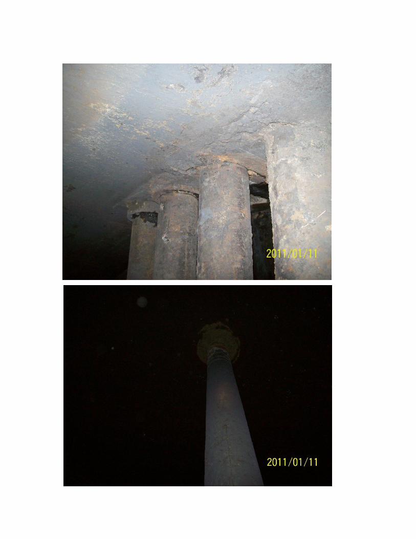

Photo 11: Damaged concrete pipe support

Photo 12: Wall crack at copper pipe location

Photo 13: Wall crack at bottom of wall/brick joint; no brick vents were observed

Photo 14: Efflorescence on north brick wall

Photo 15: Cracking and spalling of brick surfaces


Photo 16: Cracked and spalled mortar joint at base of brick wall

Mechanical Conditions
The mechanical inspection included the observation of the mechanical equipment inside the digester which includes three perimeter mixers and one center mixer; four 300 mm diameter sludge withdrawal pipes, two sludge 200 mm overflow pipes and one 150 mm transfer pipe.
Withdrawal Pipes
The four withdrawal pipes, which extend from the side wall at the control building basement to the four floor sumps, are made of ductile iron (DI) with carbon steel (CS) bolts in the flanges. The pipes are supported on concrete saddles and tied down with stainless steel clamps. The DI pipes, concrete saddles and stainless steel clamps are in good condition. The CS bolts are corroded. There are some corrosion spots shown on the exterior walls of the four withdrawal pipes. The corrosion appears to be general corrosion in nature.
Perimeter Mixer Pipes
The bottom discharge pipes (discharge when operated in “forward” direction) of the three perimeter mixers are in good condition. The upper intake pipe exteriors show signs of corrosion. The corrosion appears to be general corrosion in nature but this has to be confirmed by close inspection since observation was from a distance away on the tank floor. The inside of the draft tubes were not inspected as they are not accessible.
Centre Mixer Pipe
The bottom portion of the center mixer is in good condition except there is localized corrosion near legs and leg/tube connections (near welds). At these locations corrosion appears to be general surface corrosion.
The draft tube and impeller on the upper portion show signs of corrosion. The corrosion appears to be general surface corrosion in nature but this has to confirmed by close inspection was from a distance away on the tank floor.
Transfer Pipe
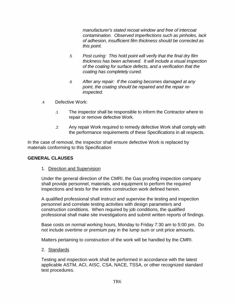
The transfer pipe is a DI pipe. It is located on the east side of the vertical pipes from the overflow chamber. The pipe and its wall supports show minor signs of corrosion.
The middle overflow pipe appears to be stainless steel pipe and has some signs of minor corrosion on the upper portion.
The material of the west side overflow pipe could not be determined in the field (may be either stainless steel or carbon steel). It is a welded pipe. The upper portion has signs of corrosion.

Mechanical Photos
Photo 17: Corrosion shown on withdraw wall pipes
Photo 18: Corrosion shown on the bottom of the feed wall pipes

Photo 19: Minor surface corrosion shown on the steel bolts of the DI withdrawal piping
Photo 20: Corrosion shown on the leg of the center mixer

Photo 21: Corrosion shown on the center mixer impeller

Photo 22: Typical of corrosion on the upper discharge pipes of the 3 perimeter mixers
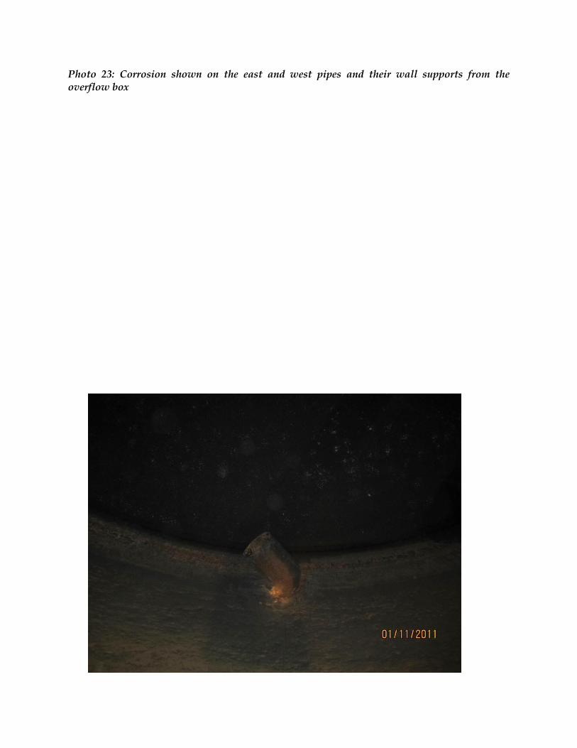
Photo 23: Corrosion shown on the east and west pipes and their wall supports from the overflow box


Summary
The digester was found to be in generally good condition. Exterior repairs are required to prevent moisture penetrating from the outside before application of new interior coatings. This includes foundation crack repair and masonry repairs, as well as roof wearing slab repair and sealing.
The floor slab appeared in good condition except one floor crack which requires repair, shown in Photo #6. Further inspection when the tank is empty and dry and the groundwater table is high is required to determine the location(s), if any, of ground water penetration. This does not appear to be a significant problem. Some cracks in the concrete wall and roof slab as well as areas of corroded concrete are anticipated under the existing failed coatings. Complete coatings removal and replacement is required. Detailed inspection to determine the repair strategy is required after coatings removal.
As is typical, the piping and equipment in the gas space or gas/liquid mixed layer exhibit more corrosion than those submerged in the liquid. There is some degree of corrosion shown on the wall pipes. There are varying degrees of corrosion shown on some carbon steel bolts. Most corrosion appears to be localized surface corrosion; however the upper parts of the mechanical systems have not been closely inspected and require inspection when scaffold is available to provide better access to determine severity of the corrosion.
Repairs and Replacements
It is recommended that the withdrawal pipe valves are removed, cleaned and repaired or replaced as required. This work is anticipated to be completed by the City. The City should also flush the remainder for the sludge lines not cleaned by Entec.
The terms of reference for repairs and replacements will include the following items:
Cleaning, crack repair and waterproof coating of the exterior roof slab.
Removal and replacement of the upper portion of the exterior brick veneer where cracking and spalling is evident. Removal and replacement of the vapour barrier between the bricks and concrete side wall of the tank may also be required.
Remove all cement mortar at the base of brick wall to provide masonry drains and provide larger air vents at the top of brick wall.
Crack repair of exterior foundation may be required if the cracks extend deeper than the parge coating.
Complete removal and replacement of all existing gasproofing by water blasting and/or sandblasting; across the digester interior roof, to just below the low water level, and the entire height of the common wall with the control building.
Complete removal by water blasting and/or sandblasting and replacement of all interior waterproofing from the gasproofing termination to ground level.
Once interior surface cleaning (sandblasting) is completed, concrete crack injection repair and corroded concrete repair as required on interior floor, walls and roof of structure.

Localized sandblasting of mechanical surfaces for surface cleaning and coating repair. Coat exterior of cleaned sound DI pipe and CS bolts with epoxy or coating recommended by the coating specialist.
For general corrosion of carbon steel (and SS if applicable) surfaces, including piping as well as the centre mixer tube and impeller, sand blasting and coating may be adequate. If the CS metal surfaces are severely pitted, repair welding may be needed. This cannot be determined until the mechanical components are sandblasted.
Next Steps
The following next steps are recommended:
1 City to consider cleaning and repair or replacement of valves and flushing piping associated with Digester 1 feed and withdrawal, outside of the digester, while it is out of service.
2 City to consider performing any upcoming scheduled maintenance on the mixers or any other appurtenances, including gas system mechanical components, while the digester is out of service. City should remove and service the mixers and impellers, as recommended by the manufacturer.
3 City to prepare and tender digester repairs and coatings contract. Roof slab repair and exterior weatherproofing must be completed prior to application of new coatings. It may be completed at the same time as coatings removal and surface repairs.
CH2M HILL recommends inspection of all interior surfaces and mechanical components after
sand blasting to determine the extent of failure and any additional repairs required

TR1
TERMS OF REFERENCE FOR CONSTRUCTION MANAGEMENT AND INSPECTION FOR THE REPAIRS AND
GASPROOFING OF DIGESTER NO.1 AT THE GUELPH WASTEWATER TREATMENT PLANT
BACKGROUND
The work generally consists of Repairs and Gas proofing, obtaining TSSA approval and commissioning the Digester No.1 that has been cleaned out in February this year and placing back into service the primary digester No.1 at the Guelph Wastewater Treatment Plant (WWTP), in Guelph, Ontario. Tender documents for the Repairs and Gas proofing to the Digester No.1 can be found on the City’s website http://guelph.ca/business.cfm?subCatID=981&smocid=1566 under contract number 11-131. Attached is the inspection report prepared after the cleaning was carried out.
LOCATION OF THE WORK
The Guelph WWTP is located at 530 Wellington Street South, Guelph, Ontario, Canada.
GENERAL SCOPE OF WORK: Construction management resident Inspector (CMRI) from Main Consulting Engineering firm and Gas proofing site inspection (GPSI) This will include but not be limited to:
Provide part time on-site inspection services for main consultant and full time inspection of Gas proofing inspector. The main Consulting Engineering firm shall have minimum of 3- 4 Digester construction projects experience. CMRI, with directly related relevant experience with a minimum of 3-4 years on wastewater treatment projects and 1-2 Digester projects will be necessary Sub contract a 3rd party independent gas proofing inspection company with minimum of 3-5 years experience in Digester gas proofing projects for Municipalities and able to provide their staff with NACE certification and with a minimum of 2-3 years experience of inspecting gas proofing projects for Municipalities. Qualification and experience details shall be provided with the bid as it will be used for evaluation purposes as-well.
Owner will designate “CMRI” as owners representative when referred to as owner/client/City in the contractor’s tender document attached. Maintain written record of site works progress. Maintain a detailed photographic record of site works progress. Provide digital progress photographs of major project milestones complete with title and date on a monthly basis. Arrange to provide by-weekly reports on works. Prepare and implement procedures for timely delivery of documents etc from

TR2
contractor to client inorder to avoid delays. Establish roles and responsibilities for all stakeholders. Verify that work is carried out to the contract document and contractors proposal. Review and approve shop drawings. Identify deficiencies and prepare list. Perform structural and mechanical inspection and condition assessment before and after the scaffolding has been installed and before and after coating is removed. Prepare and submit list of additional repairs or replacement and recommend works and materials etc that will have to be included as may be necessary. Where change order will be necessary, evaluate the contractor’s quotes and recommend to the client if the rates are adequate considering current market rates etc. Review and approve contractor’s plan of works, schedule and spills plan. Review contractors hot work permit and confined space entry in comparison to Cities and co-ordinate with City and Contractor to finalize on the approach for the project. Support and advice owner for the activity related to the project. Co-ordinate and arrange for TSSA approval prior and after works based on TSSA requirements. Review, evaluate and certify contractors progress payment for client approval, where necessary. Consultant shall be responsible for review and approve contractor’s proposal for gas proofing and associated works as in the contractor’s scope and review the warranty. Check and ensure that all testing, calibration and manufacturers start-up reports, all maintenance information, and all other associated documentation are included in the O&M manual. Provide client with report of deficiencies with cost estimate prior to issuing Substantial Completion Certificate. TIME FOR COMPLETION FOR THE CONTRACT FOR CONTRACTOR
The City anticipates that Repairs and Gas proofing of the Digester will take approximately 16 weeks including the gas tightness test.
Scope of work for Construction management resident Inspector (CMRI) In order to successfully fulfill the objectives of the assignment, active involvement from the inspector will be required. The role of the CMRI for the consultant team will include but not be limited to:
• Acting as the main contact person between the consultant firm and the Wastewater treatment plants project manager to ensure timely and accurate communication.
• Developing and facilitating the meetings with all key stakeholders.
• ensuring a high quality of work and approving shop drawings as necessary in a timely manner
• Review the contractors staging area and recommend any reinstatement etc
• Ensuring the consultant team resources is appropriately utilized and budgets managed during all aspects of the assignment.
• playing a significant role in presenting information and responding to questions during the progress of works
• The site inspector shall meet with City Project Manager when necessary but not less than twice per month during all stages of the assignment.

TR3
• Prepare and distribute meeting agendas and all information to be reviewed at the meeting not less than 3 business days prior to the meeting. Prepare and distribute summaries of the meetings not more than 3 working days after the meeting.
• Develop procedures etc as may be necessary to be able to control/manage the project
• All other related works as in this document and based on the attached contractor’s tender document.
• Proactive approach to mitigate any possible spills, quantifying for payment to contractor, monitoring hours spent by consultants staff and their subs etc.
• Co-ordinate staff for inspection in a timely manner and provide reports to client
• If staff proposed in bid is not available for the project, provide resumes and rates for the new staff for City approval. City reserves the right to approve/disapprove the staff for the project.
• Witnessing Testing and commissioning Scope of work for Gas proofing site Inspection Company for inspection and testing services (GPSI) Inspection of Gas proofing Surface Preparation and Coating Application
Supply all labour, materials, and equipment necessary to carry out the inspection and testing services described below. The general work shall include but not be limited to review and approve contractors proposal/shop drawings for gas proofing, Inspection of gas proofing surface preparation and coating application.
Inspect the surface preparation of the concrete substrate for compliance with Specification Section 07196. Notify the Contract Administrator’s resident inspection staff when all surface preparation has been successfully completed.
Witness and inspect the application of the gasproofing coating for compliance with Specification Section 07196.
Inspect the gasproofing surface preparation and coating application and submit written reports in accordance with Section 07196.
Inspect the gasproofing coating before the end of the warranty period to evaluate the performance of the work, in accordance with Specification Section 07196.
The approved gasproofing coating system selected by the contractor includes the following products:
Concrete:
1. Surfacer: TBD 2. Primer: TBD 3. Topcoat: TBD

TR4
• Field Quality Control
.1 General Requirements:
.1 All material and equipment furnished, and work done under this Section, shall be subject to inspection by skilled technical representatives to ensure that the surface preparation and coating installation work is executed in a manner that meets the application requirements specified in the Contract.
.2 Inspector’s services will include the following:
.1 Verify that coatings and other materials are as specified in the Contract and meet all quality parameters provided by the supplier.
.2 Verify that surface preparation and application are as specified in the Contract or by the coating manufacturer, whichever has the most stringent requirements. Verify that coverage and coating usage correspond with that specified in the Contract. This will be completed by monitoring the surface area coated and coating consumption.
.3 Coating Defects: Check coatings for film characteristics or defects that would adversely affect performance or appearance of coating systems.
.4 Report:
.1 Submit weekly written reports describing inspections made and actions taken to correct nonconforming Work.
.2 Report nonconforming Work not corrected.
.3 Submit copies of report to the Engineer and the Contractor, at the end of each week.
.5 General A Quality Assurance Report should be completed by the Contractor for each of the operations. Conditions as noted in this Specification or required by the coating manufacturer shall be monitored and recorded on this quality assurance report. As a minimum it should record the environmental conditions, the identification of Work completed, visual examination results, and coating consumption, and the coverage readings for the Work completed that day. This report shall be made available to the Engineer or the City upon request.
.6 Visual Examination The cured coating shall be generally smooth and free of sharp protrusions. It should not exhibit any cracking, blisters, off-ratio

TR5
discolouring, sticky spots, uncovered areas or spots, pigment separation, and other defects due to improper application. Areas with these defects shall be repaired or recoated according to repair procedures as required by the coating manufacturer.
.7 Film Thickness
.1 Thickness determinations using a Type 1 or Type 2 thickness gauge shall be conducted in accordance with the SSPC-PA2 procedure.
.2 Mark areas where the required DFT has not been reached. These areas are subject to be recoated or repaired according to repair procedures as required by the coating manufacturer.
.3 Dry film gauges shall be calibrated a minimum of once per day in accordance with SSPC PA2.
.4 Dry film gauges shall be calibrated in the work area where they are to be used.
.5 All dry film readings of Type 1 gauges shall be reduced by the average magnetic base reading determined in accordance with SSPC PA2. This value shall be recorded on the Quality Assurance Report.
.6 Use ultrasound gauges to measure and confirm DFT as per SSPC PA-2.
.3 Work Stages:
.1 Specific inspections are required for each Work stage.
.2 The minimum number of critical stages requiring inspection is:
.1 After abrasive blast cleaning to remove previously applied coating and after grouting voids.
.2 After application of surfacer and before commencement of coating application.
.3 During coating application the ambient conditions and wet film thickness readings should be monitored and confirmed to meet the project specifications.
.4 After application of coating. After each coating the film thickness should be checked, verified that each individual coat is ready to receive the next coat, and is within the
TR6
manufacturer’s stated recoat window and free of intercoat contamination. Observed imperfections such as pinholes, lack of adhesion, insufficient film thickness should be corrected as this point.
.5 Post curing: This hold point will verify that the final dry film thickness has been achieved. It will include a visual inspection of the coating for surface defects, and a verification that the coating has completely cured.
.6 After any repair: If the coating becomes damaged at any point, the coating should be repaired and the repair re-inspected.
.4 Defective Work:
.1 The inspector shall be responsible to inform the Contractor where to repair or remove defective Work.
.2 Any repair Work required to remedy defective Work shall comply with the performance requirements of these Specifications in all respects.
In the case of removal, the inspector shall ensure defective Work is replaced by materials conforming to this Specification GENERAL CLAUSES
1. Direction and Supervision
Under the general direction of the CMRI, the Gas proofing inspection company shall provide personnel, materials, and equipment to perform the required inspections and tests for the entire construction work defined herein.
A qualified professional shall instruct and supervise the testing and inspection personnel and correlate testing activities with design parameters and construction conditions. When required by job conditions, the qualified professional shall make site investigations and submit written reports of findings.
Base costs on normal working hours, Monday to Friday 7:30 am to 5:00 pm. Do not include overtime or premium pay in the lump sum or unit price amounts.
Matters pertaining to construction of the work will be handled by the CMRI.
2. Standards
Testing and inspection work shall be performed in accordance with the latest applicable ASTM, ACI, AISC, CSA, NACE, TSSA, or other recognized standard test procedures.

TR7
3. Owner’s Rights
The City of Guelph has the right, at any time, to approve or disapprove any person assigned to perform services.
4. Test Reports
Immediately after performing tests or inspections, GPSI shall verbally inform the CMRI of test results and conclusions.
A report shall be promptly submitted each week and shall be in a form approved by the City of Guelph and shall contain the following information:
.1 Name of the project and its location.
.2 Name of organization and person(s) doing inspection or test.
.3 Name of Contractor or Subcontractor performing the work.
.4 Date the inspection or test was performed.
.5 Location of the materials tested within the project; i.e. identification of test area locations in relation to structure. .6 Source of material inspected or tested; material production and delivery documentation. .7 Type of test or inspection performed. .8 Referenced Standards; i.e. CSA, ASTM, etc. .9 Data collected. .10 Name of person(s) writing the report. .11 Date the report was written. .12 Signatures of data collector(s) and report writer(s).
Formats of test and inspection reports are to be submitted to and approved by the City of Guelph before commencing with actual testing and inspection. The test reports shall be sequentially numbered. Submit proposed format for approval.
5. Report Distribution
The signed reports shall be submitted by the GPSI to the City of Guelph, the CMRI, within five (5) working days of the inspection or testing.
6. Schedule
The anticipated schedule for the inspection and testing services, based on the general contractor’s current construction schedule, is shown below. The schedule is approximate only and is subject to change. Digester: July 2011 – October 2011

TR8
Provide the following for City to Review Proposals Qualification & Experience Evaluation of relevant qualifications and expertise of assigned staff and sub consultant staff members (Details of projects and staff involvement on the project should be provided. Staff should have adequate qualifications and training including confined space entry training) Methodology Should include the understanding and approach to the project and quality assurance and completeness References Provide at least three project references with a similar scope and type Where possible include at least one municipal reference. Describe the nature of the projects including budget, schedule, person resources and scope. The City reserves the right to contact other references than the ones submitted.