guardrail common sensor (gr/cs) program summary
TRANSCRIPT

GUARDRAIL COMMON SENSOR (GR/CS)PROGRAM SUMMARY
andSYSTEM DESCRIPTION
FinalRevision 0.6
15 April 1994
Prepared forProgram Manager
Electronic Warfare/Reconnaissanceand Target Acquisition
Fort MonmouthNew Jersey 07703-5304
and
Program Executive OfficeIntelligence and Electronic Warfare
Vint Hill FarmsWarrenton, Virginia 22186

COORDINATION
REVIEWED BY: Date:
Stephen T. MakrinosChief, Systems Integration DivisionPM EW/RSTA
CONCURRED BY: Date:
LTC. Darrell LancePM GuardrailFort MonmouthNew Jersey
APPROVED BY: Date:
Marty BurgerProgram Office PEO-IEW Fort Monmouth,Electronic Warfare/ReconnaissanceSurveillance and Target Acquisition
Prepared for the Guardrail Program Office by Modern Technologies Inc.under contract number: DAAB07-91-D-J268, Task Order 8038-005

II
FORWARD
Army force structure in the new world political environment, joint precision targetingrequirements, and adapting to new threats and coping with the accelerated technologyrevolution are the drivers of today's GUARDRAIL pre-planned technology insertionprogram.
Today's rapidly changing world situation, ever evolving threats, and the rate of technologyadvances that quickly cause hardware to become obsolete are critical issues in the GuardrailCommon Sensor Systems 1 and 2 program. The Guardrail mission has been extended to support awide range of conflicts and training scenarios required for CONUS/OCONUS bases and split baserapid deployment operations. The ability to support the commander with offensive intelligencefrom a stand-off platform, with a unique view of the battlefield from up to three platforms, and toprecisely locate a wide range of conventional and exotic targets with Product ImprovementPrograms (PIP's) are the 1990's Guardrail program objective.
It has been shown that the way to avoid obsolescence does not rest on attempting to puttechnological progress on hold or by standardizing on specific hardware but rather by employingindustry accepted standards that are open to all. These standards must include fiber optic busstructures, software language with development standards, operating systems and standardinterface protocol. Modern EW systems are heavily processing/software oriented. Much of theadaptability required for solving the EW operational problems are truly software dependent.Modern Guardrail system functions are mostly software based and could use a variety ofworkstations and processors to perform these software functions so long as they abide by theestablished standards and have sufficient power and interfaces to support the requirement.
Much of the system special processing and unique equipment in Guardrail, such as the datalink/sensors/signal processing, are being developed by co-contractors or were developedindependent of Guardrail. These components find their way into the system via the system'sProgrammable Adapter Modules (PAM's) which also employ standards and are able to adapt anynon-standard interfaces to the system.
Use of open standard architecture is the best way to overcome the exponentially rising technologyadvances that otherwise also carry obsolescence as its downside.
The new Guardrail system with distributed architecture employs extensive bus structures based onstandards that allow the Guardrail capability to grow and evolve to handle changing environments.It is also adaptable to various other platforms and to system sizing. This modern architecture isalso its insurance that the inevitable hardware obsolescence will not prevent the system's mostexpensive element, namely its software, from continuing to operate in the system even if hardwarecomponents may require substitution because of obsolescence. Further, it will more readily allownew capabilities from third party sources to be integrated into the system.
Guardrail has a heritage of successful programs that have met the signal intelligencechallenge over 20 years.
Guardrail was the first remotely controlled airborne COMINT system with ground basedprocessing and reporting capabilities. The original Guardrail objective to collect signalintelligence from a stand-off range and to support near real time reporting of critical intelligenceto the field commander has not changed. Initially, the Guardrail collection and location

III
measurements were mainly for identifying activity, obtaining approximate location, associatingnets and performing situational analysis on collected voice data. This objective has consistentlybeen executed very successfully. Although the DF performance has significantly improved overthe years, and has proven very effective for finding and tracking enemy tactical forces, thedirection of arrival (DOA) DF principle does not permit sufficient accuracy to support lethaltargeting. However, recent GR/CS program product improvements have incorporated the timedifference of arrival (TDOA) and differential dopler (DD) location measurement principle thatdoes have the target location accuracy to support tasking required for Quick Fire targeting.
The increased timeliness of acquiring targeting accuracy Signal Intelligence, along with theintegration of the one channel LRIP CTT, and the two and three channel CTT's with their multiprotocols, enables Guardrail to quickly relay reports to Tactical Analysis Centers (TAC's) andfield commanders. The CTT/H-R "receive only terminal" provides the capability fordissemination of collateral tactical reports directly to the shooter in time to use it to the greatestadvantage. This requirement for precision accuracy and quick delivery of reports has been a veryhigh priority in the recent and on-going Guardrail product improvement programs.
The current Guardrail technology insertion program provides the precision targeting and has theproduct dissemination to tactical commanders so that tactical consumers can make rapid use ofpre-processed responses to their tasking relative to formulation of battle plans. Theseenhancements insure that the system will be effective against the evolving threats in today'schanging political climate and will support the Army's joint Quick fire targeting requirement.Response to tasking inputs supports the field commander in developing the battle plan andprovides fresh intelligence updates that assists him in adjusting that plan as events develop.
This Guardrail Common Sensor Program Summary and System Description Document isstructured to provide a historical background and to develop an understanding of systemcapabilities, technical features and operational deployment considerations for those needinga general overview (and) at a top level it includes specific information on the Guardrailfamily of pre-planned product improvement programs.
The document provides a progressive summary of the product improvements, an outline of systemlevel specifications and an overview of system characteristics, some insight into operation anddeployment. It covers each of the currently fielded and planned Guardrail systems.
The document has been reviewed by the various project engineers for technical content and by theProgram office to insure that it clearly achieves its stated objectives.

IV
Table of Contents
Section Page
1.0 Introduction and Executive Overview........................................................................... 11.1 On-going Preplanned Product
Improvement Program Overview .................................................................................. 11.1.1 Program Evolution via Technology Insertion Programs ............................................... 11.1.2 Traditional Guardrail Developmental Approach........................................................... 11.1.3 Guardrail System overview ........................................................................................... 41.1.4 Mission Capability Growth ........................................................................................... 71.2 Historical Overview ...................................................................................................... 121.2.1 Early Guardrail systems ................................................................................................ 121.2.1.1 Guardrail I..................................................................................................................... 131.2.1.2 Guardrail II ................................................................................................................... 131.2.1.3 Guardrail IIA................................................................................................................. 161.2.1.4 GR-IV ........................................................................................................................... 161.2.1.5 Early Guardrail Program Performance.......................................................................... 191.2.2 GR-V History................................................................................................................ 191.2.3 IGR-V History............................................................................................................... 241.2.4 GR/CS Systems 3 & 4 Background............................................................................... 251.2.5 GR/CS System 1 (Hybrid system) and GR/CS System 2
(Objective System) Background Overview.................................................................. 271.3 Program schedule.......................................................................................................... 30
2.0 System Description ....................................................................................................... 312.1 System Capability Matrix.............................................................................................. 312.2 GR-V Description and Capabilities............................................................................... 312.2.1 GR-V Description and Capability Summary ................................................................. 362.2.2 GR-V IPF...................................................................................................................... 362.2.2.1 Analyst Van................................................................................................................... 362.2.2.2 Communications/Computer Van ................................................................................... 412.2.2.3 Operator Van................................................................................................................. 432.2.3 GR-V ARF's .................................................................................................................. 462.2.4 Aircraft.......................................................................................................................... 462.2.5 GR-V AGE.................................................................................................................... 512.2.6 Tactical Commander's Terminal (TCT) ........................................................................ 512.2.7 GR-V Satellite Remote Relay ....................................................................................... 512.2.8 Interference Mitigation.................................................................................................. 542.2.9 GR-V Employment ....................................................................................................... 542.2.9.1 Site Preparation and IPF Installation............................................................................. 542.3 IGR Description and Capabilities ................................................................................. 562.3.1 IGR-V IPF..................................................................................................................... 602.3.2 IGR-V ARF................................................................................................................... 662.3.3 RC12-D Aircraft ........................................................................................................... 692.3.4 IGR-V AGE Subsystem ................................................................................................ 692.3.5 Interoperable Data Link ................................................................................................ 742.3.6 Improved Tactical Commander's Terminal (ICTT) ...................................................... 742.3.7 IGR-V Employment ...................................................................................................... 78

V
2.3.7.1 Site Preparation and IPF Installation............................................................................. 782.3.7.2 ARF/AGE Checkout Procedures................................................................................... 782.3.7.3 Mission Initialization .................................................................................................... 812.3.7.4 Mission Deployment ..................................................................................................... 812.3.7.5 Operator Responsibilities .............................................................................................. 812.3.7.6 Flight Tracks ................................................................................................................. 822.3.7.6.1 Flight Tracks For Single aircraft ................................................................................... 822.3.7.6.2 Flight Tracks For Dual aircraft...................................................................................... 822.3.7.7 Mission Shutdown......................................................................................................... 842.4 GR/CS System 3 and GR/CS System 4
Description and Capabilities ......................................................................................... 842.4.1 Guardrail Common Sensor IPF ..................................................................................... 882.4.1.1 Analyst Van................................................................................................................... 882.4.1.2 Computer Van ............................................................................................................... 942.4.1.3 Communications Van.................................................................................................... 942.4.1.4 Operator Van................................................................................................................. 952.4.2 Interoperable Data Link ................................................................................................ 952.4.3 Guardrail Common Sensor ARF ................................................................................... 962.4.3.1 The ARF Prime Mission Equipment (PME). ................................................................ 962.4.3.2 GR/CS Aircraft ............................................................................................................. 992.4.4 Guardrail Common Sensor AGE................................................................................... 992.4.5 Support Equipment ....................................................................................................... 1032.4.5.1. AN/ARM-185B Airfield Maintenance Facility............................................................. 1032.4.5.2 AN/GMS-271B IPF Maintenance Facility. ................................................................... 1032.4.5.3 AN/GSM-624 AQL/CHAALS Maintenance Van. ........................................................ 1032.4.5.4 Power Distribution System............................................................................................ 1032.4.6 Used With Equipment ................................................................................................... 1032.4.6.1 The Commander's Tactical Terminal (CTT). ................................................................ 1032.4.6.2 Remote Relay System (RRS) (Future) .......................................................................... 1042.4.7 QRC Enhancement Add-ons ......................................................................................... 1042.4.8 Guardrail Common Sensor Employment....................................................................... 1042.4.8.1 Site Preparation and Installation ................................................................................... 1042.4.8.1.1 ARF/AGE Checkout Procedures................................................................................... 1062.4.8.1.2 Mission Initialization .................................................................................................... 1062.4.8.1.3 Mission Planning........................................................................................................... 1092.4.8.1.4 Operator Responsibilities and System Tasking ............................................................. 1092.4.8.2 Operational Concept ..................................................................................................... 1102.4.8.2.1 Guardrail Garrison Standard Operations....................................................................... 1102.4.8.2.2 Guardrail Garrison Single Aircraft................................................................................ 1102.4.8.3 Standard Flight Information .......................................................................................... 1122.4.8.3.1 Flight Tracks ................................................................................................................. 1122.4.8.3.2 Flight Tracks for a Single Aircraft ................................................................................ 1172.4.8.3.3 Flight Tracks for Two Aircraft...................................................................................... 1172.4.8.3.4 Calibration Tracks......................................................................................................... 1172.4.8.3.5 Altitude Selection.......................................................................................................... 1172.4.8.3.6 Attaining Altitude.......................................................................................................... 1182.4.8.3.7 Synchronization and Turns............................................................................................ 1192.4.8.3.8 Data Link Considerations.............................................................................................. 1192.4.8.3.9 Navigation System Operations ...................................................................................... 1192.4.8.3.10 GPS To Backup Switching............................................................................................ 1192.4.8.3.11 Ground Speed and Direction......................................................................................... 1192.4.8.3.12 Ground Speed and Direction......................................................................................... 1192.4.8.4 Scan Plan Definition ..................................................................................................... 1202.4.8.5 Security Accreditation................................................................................................... 1202.5 GR/CS System 1 ........................................................................................................... 121

VI
2.5.1 System 1 Distributed Processing IPF ............................................................................ 1252.5.1.1 Open Architecture ......................................................................................................... 1312.5.1.2 Language/Operating System ......................................................................................... 1322.5.1.3 Main System Computers ............................................................................................... 1322.5.1.4 Operator Workstations .................................................................................................. 1322.5.1.5 Audio Storage ............................................................................................................... 1342.5.1.6 Data Distribution System/Reporting ............................................................................. 1342.5.1.7 Special Signal Processor (Proforma)............................................................................. 1342.5.1.8 Smart File Cabinet/FasTrack Mission Management Tools ........................................... 1342.5.1.9 IPF Vans ....................................................................................................................... 1352.5.2 System 1 ARF ............................................................................................................... 1352.5.3 Aircraft.......................................................................................................................... 1372.5.4 System 1 AGE............................................................................................................... 1372.5.5 System 1 LRIP CTT...................................................................................................... 1372.5.6 System 1 Satellite Remote Relay................................................................................... 1452.5.7 Support concept ............................................................................................................ 1452.5.8 System Operational Employment/Operational Concept ................................................ 1452.5.8.1 Operator Responsibilities and System Tasking ............................................................. 1482.5.8.2 System Operational Scenarios....................................................................................... 1492.5.8.2.1 Guardrail Garrison Tethered Standard Operations........................................................ 1492.5.8.2.2 Guardrail Garrison Tethered Single Aircraft................................................................. 1502.5.8.2.3 Quick Deployment Tactical Tethered Operations ......................................................... 1512.5.8.2.4 Air Force Tethered Interoperable Operations ............................................................... 1522.5.8.2.5 Army Tethered Interoperable Operations...................................................................... 1532.5.8.3 Standard Flight Information .......................................................................................... 1542.5.8.3.1 Flight Tracks ................................................................................................................. 1542.5.8.3.2 Flight Tracks for a Single Aircraft ................................................................................ 1582.5.8.3.3 Flight Tracks for Two Aircraft...................................................................................... 1582.5.8.3.4 Calibration Tracks......................................................................................................... 1592.5.8.3.5 Altitude Selection.......................................................................................................... 1592.5.8.3.6 Attaining Altitude.......................................................................................................... 1602.5.8.3.7 Synchronization and Turns............................................................................................ 1602.5.8.3.8 Data Link Considerations.............................................................................................. 1602.5.8.3.9 Navigation System Operations ...................................................................................... 1602.5.8.3.10 Ground Speed and Direction......................................................................................... 1612.5.8.4 Scan Plan Definition ..................................................................................................... 1612.5.8.5 Security Accreditation................................................................................................... 1612.6 GR/CS Objective System Description (System 2) ........................................................ 1622.6.1 System Enhancements ................................................................................................... 1652.6.2 System 2 Architecture Overview................................................................................... 1692.6.2.1 Ground Segment Architecture....................................................................................... 1692.6.2.2 Airborne Segment Advanced Tactical SIGINT Architecture........................................ 1712.6.2.3 Support Segment Architecture ...................................................................................... 1752.6.3 System 2 Definition....................................................................................................... 1752.6.3.1 IPF Segment.................................................................................................................. 1812.6.3.2 ARF Segment ................................................................................................................ 1812.6.3.3 MMV Segment/Support Segment ................................................................................. 1912.6.3.4 Three Channel CTT Segment........................................................................................ 1912.6.3.5 Aircraft.......................................................................................................................... 1962.6.3.6 Multi Role Data Link .................................................................................................... 1962.6.4 Accreditation................................................................................................................. 1972.6.5 Embedded Training....................................................................................................... 1972.6.6 Sensor Management PIP's ............................................................................................. 2002.6.7 Support concept ............................................................................................................ 2012.6 8 System Employment/Operational Concept.................................................................... 203

VII
2.6.8.1 Operator Responsibilities and System Tasking ............................................................. 2052.6.8.2 System Operational Scenarios....................................................................................... 2072.6.8.2.1 Guardrail Garrison Tethered Standard Operations........................................................ 2072.6.8.2.2 Guardrail Garrison Tethered Single Aircraft (GGTSA)................................................ 2082.6.8.1.3 Quick Deployment Tactical Tethered Operations ......................................................... 2092.6.8.2.4 Quick Deployment Tactical Untethered Operations...................................................... 2102.6.8.2.5 Air Force Tethered Interoperable Operations ............................................................... 2112.6.8.1.6 Army Tethered Interoperable Operations...................................................................... 2122.6.8.2.7 Extended Tethered Range Air-to-Air (future) ............................................................... 2122.6.8.3 Standard Flight Information .......................................................................................... 2162.6.8.3.1 Flight Tracks ................................................................................................................. 2162.6.8.3.2 Flight Tracks for a Single Aircraft ................................................................................ 2192.6.8.3.3 Flight Tracks for Two Aircraft...................................................................................... 2202.6.8.3.4 Calibration Tracks......................................................................................................... 2202.6.8.3.5 Altitude Selection.......................................................................................................... 2202.6.8.3.6 Attaining Altitude.......................................................................................................... 2212.6.8.3.7 Altitude and Attitude..................................................................................................... 2222.6.8.3.8 Synchronization and Turns............................................................................................ 2222.6.8.3.9 Data Link Considerations.............................................................................................. 2222.6.8.3.10 Navigation System Operations ...................................................................................... 2222.6.8.3.11 Ground Speed and Direction......................................................................................... 2232.6.8.3.12 Roll and Pitch Limitations............................................................................................. 2232.6.8.4 Scan Plan Definition ..................................................................................................... 2232.6.8.4.1 Scan Plan 1 Combined .................................................................................................. 2232.6.8.4.2 Scan Plan 2 LPI............................................................................................................. 2242.6.8.4.3 Scan Plan 3Conventional .............................................................................................. 2242.6.8.4.4 Scan Plan 4 Full-band LPI Copy................................................................................... 2242.6.8.4.5 Scan Plan 5 Sub-band LPI copy.................................................................................... 224
3.0 Pre-planned Capability Growth..................................................................................... 2253.1. System 1 P3I Upgrades ................................................................................................. 2253.1.1 Airborne Auto Frequency Division Demultiplxer (FDDM).......................................... 2253.1.2 Narrow Band/Wide Band Proforma.............................................................................. 2263.1.3 CHAALS Supervisor Console....................................................................................... 2263.1.4 Auto Multi-level Reporting ........................................................................................... 2263.1.5 Accreditation Upgrade .................................................................................................. 2263.1.6 Mission Management Enhancements ............................................................................ 2273.1.7 ASE Suite Upgrade ....................................................................................................... 2273.1.8 CHAALS/ELINT Remote Operation ............................................................................ 2273.2 System 1 Potential Retrofits .......................................................................................... 2283.2.1 Three Channel CTT retrofit .......................................................................................... 2283.2.2 Unified Architecture/LPI Payload Retrofit ................................................................... 2283.2.3 Single Panel Pod Retrofit/Weight Reduction ................................................................ 2283.2.4 Embedded Training....................................................................................................... 2293.2.5 Interoperability Enhancements..................................................................................... 2293.2.6 Direct Airborne Satellite Relay ..................................................................................... 2303.2.7 Drop-on Receiver.......................................................................................................... 2303.2.8 ELINT On-board Enhancements................................................................................... 2303.3 System 2 P3I Enhancements ......................................................................................... 2303.3.1 ASE Expansion ............................................................................................................. 2313.3.2 Accreditation Upgrade .................................................................................................. 2313.3.3 Drop-on Receiver.......................................................................................................... 2313.3.4 ATSA Embedded Band 1 Receiver/DF......................................................................... 2323.3.5 Air-to-Air Linkup.......................................................................................................... 2323.3.6 On-board CHALS-X Processing ................................................................................... 233

VIII
3.3.7 ELINT On-board Processing......................................................................................... 2333.3.8 ELINT Ground Processing upgrade.............................................................................. 2343.3.9 Auto Multi-level Reporting ........................................................................................... 2343.3.10 Direct Airborne Satellite Relay ..................................................................................... 2353.3.11 Interoperability Enhancements...................................................................................... 2363.3.12 ARF Roundout .............................................................................................................. 2373.3.13 Automated Proforma Upgrade ...................................................................................... 2373.3.14 CHALS-X LPI Tasking................................................................................................. 2373.3.15 Sensor Management/QUICKFIRE................................................................................ 237

IX
LIST OF FIGURES
Figure1.1.2-1 Guardrail Capabilities Evolution1.1.2-2 Guardrail Technology Evolution1.1.3-1 GR/CS AN/USD-9 US Army SIGINT Targeting System1.1.3-2 Typical System Operational Configuration1.1.4.1 Guardrail Operational Concept1.1.4.2 Guardrail Signal Environment1.1.4.3 Tactical Intelligence Dissemination Concept1.1.4.4 Evolving Fire Support Architecture to Support Deep Strike1.2.1-1 Initial Guardrail IPF Configuration1.2.1-2 Initial Guardrail DF Aircraft Configuration1.2.1-3 Guardrail II DF/Intercept Workstations1.2.1.4-1 GR-IV Flight Line Support1.2.2-1 GR-V RU-21H Aircraft1.2.2-2 GR-V IPF Vans1.2.2-3 GR-V IPF Operator Stations1.2.5-1 GR/CS SIGINT Wide Area Network1.3-1 GR/CS Acquisition Schedule1.3-2 Technology Flow Chart
2.2-1 GR-V System Concept2.2.2-1 GR-V IPF Van Layout2.2.2-2 GR-V IPF Functional Block Diagram2.2.2.2-1 GR-V Computer/Test Operator Position2.2.2.3-1 GR-V DF Operator Positions 1-82.2.2.3-2 GR-V Computerized Operator Position2.2.3-1 GR-V Aircraft and AN/ARW-83(V)4 Payload2.2.3-2 GR-V ARF Functional Diagram2.2.3-3 GR-V ARF Equipment Racks2.2.4-1 GR-V Aircraft Antenna Configuration2.2.6-1 AN/TSC-87 Communications Terminal2.2.7-1 GR-V Remote Relay System Configuration2.2.9-1 GR-V IPF AN/TSQ-105(V)3 Site Layout
2.3-1 IGR-V System Operational Concept2.3-2 IGR-V System Functional Block Diagram2.3.1-1 IPF Abbreviated Block Diagram2.3.1-2 IGR-V IPF Site Configuration2.3.1-3 IGR-V IPF Van Interior Layout2.3.1-4 IGR-V IPF Van Side View2.3.2-1 IGR-V ARF Rack Layout2.3.2-2 IGR-V ARF Simplified Block Diagram2.3.3-1 IGR-V RC-12D Aircraft2.3.3-2 IGR-V RC-12D Aircraft Antenna Configuration2.3.4-1 IGR-V AGE Equipment Layout2.3.4-2 IGR-V AGE Simplified Block Diagram2.3.5-1 IGDL Equipment2.3.5-2 IDL Interface Diagram (IPF and ARF)2.3.6-1 AN/TSC-116 ICTT Communications Net2.3.6-2 ICTT Interoperability Diagram2.3.7-1 Typical IGR-V IPF Site Installation

X
2.3.7.6-1 Flight Tracks
2.4-1A GR/CS System and Associated Equipment2.4-1B GR/CS System 4 Configuration2.4-2 GR/CS System Functional Block Diagram2.4-3 GR/CS System Composition2.4.1-1 System 4 IPF Functional Diagram2.4.1-2 System 4 IPF Interior Layout2.4.3.1-1 GR/CS ARF subsystem2.4.3.1-2 ARF Functional Block Diagram2.4.3.2-1 RC-12K Mission Aircraft2.4.4-1 Auxiliary Ground Equipment (AGE) Van2.4.7-1 GR/CS System 4 QRC Enhancements2.4.8.1-1 GR/CS System Operational Diagram2.4.8.1-2 GR/CS Site Layout2.4.8.2.1-1 Guardrail Tethered Standard Operations Scenario2.4.8.2.2-1 Guardrail Tethered Single Aircraft Scenario2.4.8.3-1A 3/4 Baseline U Triad Tracks2.4.8.3-1B 135 Degree Triad Tracks2.4.8.3-1C 155 Degree Dyad Tracks
2.5-1 Guardrail System 1 Operational Concept Overview2.5-2 GR/CS System 1 Block Diagram2.5-3 GR/CS System 1 Composition2.5-4 Guardrail Common Sensor System 1 Definition2.5-6 System 1 Functional Segment Breakdown2.5.1-1 GR/CS System 1 IPF Composition2.5.1-2 System 1 IPF Interface Block Diagram2.5.1.1-1 System 1 IPF Functional Block Diagram2.5.1.1-2 Ground Segment Architectural Diagram2.5.2-1 ARF Subsystem Composition2.5.2-2 System 1 ARF Rack Layout2.5.2-3 Airborne Relay Facility Installation2.5.2-4 System 1 ARF Simplified Block Diagram2.5.3-1 RC-12N Aircraft2.5.3-2 RC-12N Antenna Locations2.5.4-1 AGE Block Diagram ??2.5.4-2 AGE Configuration2.5.5-1 CTT Field Communications Terminal2.5.6-1 System 1 Satellite Remote Relay Concept Diagram2.5.8.2.1-1 Guardrail Tethered Standard Operations Scenario2.5.8.2.2-1 Guardrail Tethered Single Aircraft Scenario2.5.8.2.3-1 Quick Deployment Tactical Tethered Operational Scenario2.5.8.2.4-1 Air Force Interop Tethered Operations Scenario2.5.8.2.5-1 Army Interop Operations2.5.8.3-1A 3/4 Baseline U Triad Tracks2.5.8.3-1B 135 Degree Triad Tracks2.5.8.3-1C 155 Degree Dyad Tracks
2.6-1 GR/CS System 2 Functional Diagram2.6-2 Antenna Coverage Diagram2.6.2.1-1 Ground Segment Architectural Diagram2.6.2.2-1 Airborne Segment Architectural Diagram2.6.2.2-2 ATSA Architectural Diagram2.6.2.2-3 CMC Chassis Configuration

XI
2.6.3-1 System 2 Composition2.6.3-2 System 2 Decomposition2.6.3-3 System 2 Definition2.6.3-5 System 2 Functional Segment Breakdown2.6.3-5 System 2 Simplified Block Diagram2.6.3.1-1 System 2 IPF Operational Configuration2.6.3.1-2 System 2 Van Configuration and Functions2.6.3.1-3 System 2 IPF Van Interior Layout2.6.3.1-4 System 2 IPF Interface Block Diagram2.6.3.2-1 System 2 ARF Subsystem Composition2.6.3.2-2 System 2 ARF Simplified Block Diagram2.6.3.2-3 System 2 Unified Payload Block Diagram2.6.3.2-4 System 2 Payload ELINT Block Diagram2.6.3.2-5 System 2 CHAALS-X Block Diagram2.6.3.3-1 System 2 MMV Functions2.6.3.3-2 System 2 Flight Line Maintenance2.6.3.4-1 CTT Channel Composition2.6.3.4-1 CTT Field Terminal Subsystem2.6.3.6-1 MRDL Direct Tether Configuration2.6.3.6-1 MRDL Air-to Air Relay Mission Configuration2.6.7-1 Support Segment Functional Diagram2.6.7-2 Support Segment Configuration Diagram2.6.8.2.1-1 Guardrail Tethered Standard Operations Scenario2.6.8.2.2-1 Guardrail Tethered Single Aircraft Scenario2.6.8.2.3-1 Quick Deployment Tactical Tethered Operational Scenario2.6.8.2.4-1 Quick Deployment Tactical Tethered Operational Scenario2.6.8.2.5-1 Air Force Interop Untethered Operations Scenario2.6.8.2.6-1 Army Interop Operations2.6.8.2.7-1 Extended Range Air to Air Relay Scenario2.6.8.2.8-1 Direct Air to Air Satellite Relay Scenario2.6.8.3-1A 3/4 Baseline U Triad Tracks2.6.8.3-1B 135 Degree Triad Tracks2.6.8.3-1C 155 Degree Dyad Tracks
3.3.10-1 DASR Aircraft Deployment Configuration3.3.15-1 Sensor Management/Quickfix Software Tools
XII
LIST OF TABLES
Table 2.1-1 System Capability Matrix
Table 2.2.1-1 GR-V System Specifications
Table 2.3-1 IGR-V System Specifications
Table 2.4-1 GR/CS Systems 3 and 4 Specifications
Table 2.4.8.2.5-1 System 4 Ground Segment Interoperability
Table 2.5-1 System 1 Specifications
Table 2.5.8.2.5-1 System 1 Ground Segment Interoperability
Table 2.6.1-1 System 2 Specifications
Table 2.6.8.2.6-1 System 2 Ground Segment Interoperability
Table 2.6-1 GR/CS System Products
APENDICES
Appendix A: GlossaryAppendix B: Operational Application Data
GUARDRAIL COMMON SENSOR (GR/CS)

2
PROGRAM SUMMARY and
SYSTEM DESCRIPTION
1.0 Introduction and Executive Overview
1.1 On-going Preplanned Product Improvement Program Overview
The current pre-planned product improvement program will soonallow the Guardrail Common Sensor system to adapt to varioussignal environments and to re-allocate sensors and processingresources to match the requirements of varying phases of amission. For example, the new unified architecture will have thenecessary flexibility to program its on-board sensor suite fordifferent mixes of conventional and exotic signals. It will becapable of re-allocating payload assets from primarilycollecting signal data to sorting of tactical data as themission progresses in response to tasking from the systemoperators. Additionally, system deployment flexibility willenable the system to adapt to the ever changing internationalpolitical scene.
1.1.1 Program Evolution via Technology Insertion Programs
The Guardrail family of systems have successfully provided theArmy with an airborne battlefield signal surveillance capabilityfor more than twenty years. A series of seven generations oftechnology insertion product improvement programs have providedmajor capability enhancements in a cost effective, timelymanner. Guardrail has grown from a manually controlled remoteCommunications Intelligence (COMINT) intercept system whosecapability was to collect tactical voice communications in orderto provide timely tactical reporting, to today's GuardrailSIGINT targeting systems that rapidly acquires and accuratelylocates SIGINT threats including radar and weapons systemscommand and control signals.
1.1.2 Traditional Guardrail Developmental Approach
Since the early 1970's, the Guardrail programs, first with QRCprototypes, then with fully supported PIP's, have provided theArmy with a fixed wing, airborne COMINT capability. Timelyfielding of modern assets has been achieved by applying low tomoderate risk, current technology to satisfy the evolving EWrequirements. Figure 1.1.2-1 illustrates past and projectedthreats and how Guardrail capabilities have kept pace. Eachsystem has improved on the capabilities and architecture of itspredecessor. This approach has proven to be an extremelyeffective method of increasing overall system effectiveness

3
against the ever changing threats and has helped to moderateprocurement and life cycle costs. Figure 1.1.2-2 shows theevolutionary timeline for the GR family of systems, the flow ofsome of the critical technologies that have been transferred toGuardrail from other programs, and the utilization of technologyfrom IR&D/Commercial-off-the-shelf (COTS).

4

5

6
1.1.3 Guardrail System overview
A typical AN/USD-9 Special Purpose Signal Detection(Guardrail) system has four major subsystems: the groundbased Integrated Processing Facility (IPF), the AirborneRelay Facility (ARF), the Auxiliary Ground Equipment (AGE)and Commanders Tactical Terminal CTT pictured in figure1.1.3-1. It also has certain associated support equipmentwhich includes maintenance facilities, storage vans and apower distribution system. A typical Guardrail mission asshown in Figure 1.1.3-2 is tethered to one, two or threespecial mission equipped aircraft deployed in stand-offflight tracks that are within line of sight to the targetedarea of interest. The system mission is to collect and locateand to analyze the collected SIGINT signal threats inresponse to higher level tasking. The system relays tacticalintelligence reports to its users.
The ground based Integrated Processing Facility (IPF)subsystem provides command/control; the airborne sensorplatforms collect the threat data; the Auxiliary GroundEquipment (AGE) supports the ARF equipment; and tacticalreporting terminals support the direct relay of reports tothe tactical commander.
The IPF has computational systems and operator stations thatprocess collected intelligence and prepare it for disseminationto field commanders via the Commander's Tactical Terminal (CTT)or land lines. The IPF has connectivity to other externalnetworks that interface to the intelligence community.
The Guardrail airborne platform consists of a specialelectronic mission (SEMA) aircraft and its payload, theAN/ARW-83(V) Airborne Relay Facility (ARF). The SEMA aircraftare derivations from the RU21 and RC12 Beech military utilityaircraft. The airframe includes navigation, avionics andsurvivability equipment. The mission payload is commonlycalled the "Airborne Relay Facility" (ARF) subsystem. The ARFhas sensor subsystems consisting of antenna arrays, DF andintercept equipment, micro processors for processing/control,and data Link communications equipment. A key part of thepayload capability is its direction finding (DF)/timedifference of arrival (TDOA) emitter location equipment.
Ground support for the payload mission sensors/linkcommunications is provided by a mobile AGE step van.
The CTT related (TRIXS GPF) equipment is integrated into theIPF. Its relay equipment is installed in the ARF and its GSE islocated in the AGE and in the maintenance van. Normally,

7
Commander's Tactical Terminals (CTT's) are located atdesignated intelligence centers and tactical operationscenters.
The currently deployed Guardrail systems are assigned between6 to 12 Mission aircraft. The number of platforms isdetermined by the aircraft maintenance cycles and the numberof on-line platforms required to support system operationalavailability. Nine to twelve is the derived number ofaircraft required in modern system to assure "surgecapability" coverage. The specified number of platforms isbased on a mix of two and three aircraft missions.(Note: High accuracy targeting missions generally requirethree aircraft sorties.)

8

9

10
1.1.4 Mission Capability Growth
Figure 1.1.4-1 shows plan view of the Guardrail operationalconcept overlaid on a typical battlefield area. Guardrailthreats are signals with tactical significance that fall withina Corps area of interest (AOI) (or) signals that have tacticalvalue in a special operations scenario. Earlier Guardrailsystems focused on VHF/UHF tactical single channel voice andmulti-channel COMINT signals. Figure 1.1.4-2 provides someinsight into the typical tactical signal environment thatGuardrail is required to operate in. Mission scenarios havetraditionally required operators to search out assigned COMINTactivity, identify the collected intercepts, gist the contentand determine the location of the high value targets (HVT's) inresponse to tasking from Corps Intelligence centers. Trafficanalysts would associate the collected battlefield COMINT dataand formulate tactical reports (TACREPS). After a review andapproval of the reports, the intelligence reports were sent viathe Commander's Tactical Terminal (CTT) digital communicationschannel or given to a communications center in the form of hardcopy or paper tape COMINT TACREP's.
Traditionally, Mission Managers have planned a mission usingsystem initialization procedures and operational frequencyband assignments prior to the mission to effectively supporttasking. System initialization parameters and operatorassignments can be modified during the mission. Computerfiles that store the situation data base (SDB) are used toanalyze the data collected by operators. Traffic analystsget their data from the operator Gist's or recorded audiodata. Location analysts use DF files to create geographictarget location data and to fill-in "emitter locationfields" in the tactical reports. The (TACREPS) after reviewby a mission manager, are released by the Tactical Operatorvia the CTT and via the operational communications channels.
Recently, TRIXS, TIBS, and TRAP/TADIXS-B nets supported bythe Three Channel CTT illustrated in figure 1.1.4-3, havebecome the new priority interfaces for ingesting externalintelligence into Guardrail, TRIXS being the disseminatingrelay for Guardrail SIGINT reports. Modern GuardrailWorkstations provide three dimensional map overlays thatsupport the operator in conversion of graphics and text datato a message format that is acceptable to the netprotocol's. The current direct tactical disseminationconcept includes sending the Guardrail intelligence reportsto tactical user's via the CTT field terminal or to themobile CTT/H-R "receive only" terminals. Fig 1.4-4illustrates current thinking as to how connectivity will be

11
incorporated for rapid battlefield dissemination to QuickFire and TOC's.
Pre-planned integration of the Advanced Quick Look (AQL)technology has added ELINT collection, EOB processing, ELINTDF and ELINT TDOA to GR/CS. Communications frequencycoverage is being extended with Lowband and microwaveintercept. More automated signal search, acquisition andrecognition features have provided significant addedflexibility and operator efficiency to the signal collectionprocess. Near first syllable detection via priority audiomonitor (PAM)/priority audio recording (PAR) has made itpossible to assure the intercept and automatic DF ofidentified threats. This enhancement has also provided theability to prioritize search and acquisitiononly in defined areas of interest.

12
Guardrail Operational Concept
Figure 1.1.4-1

13
Signal Threat Environment
Figure 1.1.4-2

14
Tactical Intelligence Dissemination Concept
Figure 1.1.4-3

15
Evolving Fire Support Architecture inSupport of Deep Strike
Figure 1.1.4-4

16
1.1.4 Mission Capability Growth(Cont)
Another important Guardrail technology insertion is theCommunications High-Accuracy Airborne Location System (CHAALS)that has provided a TDOA/DD COMINT precision target locationcapability on Guardrail Common Sensor systems.
The new GR/CS System 1 has distributed ground processing thatemploys open standards. This advancement has provided vastlyincreased IPF processing power, new deployment flexibility with 2,3 or 4 IPF vans and plenty of software processing capacity forfuture growth.
System 2, which is currently under development, will extend thedistributed processing to the on-board assets using a "unifiedSIGINT architecture" that adds real time programmability/andshared asset modularity to the payload. The on-board "unified"collection/DF/signal processing is an N Channel system. This"technology transfer" handles exotic signals and complements theGuardrail IPF Universal Workstations currently being employed inSystem 1. This distributed, unified Advanced Tactical SIGINTArchitecture (ATSA), provides a task driven SIGINT capability thatcan rapidly respond to current and evolving tactical signalenvironments by querying the airborne data base (or) via a manualmode. It is this architectural advance that is the heart of themost current Guardrail PIP. State of the art, serial, wide bandfiber optic "Data Flow" buses move the collected signals aroundthe system using a precise time code for synchronization andrecall. The unified ARF architecture uses a standard FiberDistributed Data Interface (FDDI) network to manage and controlthe on-board distributed processing equipment interfaces serialdigitized signal data to the new generation onboard Guardrail DualData Link (GDDL) which communicates with the ground based ModularInteroperable Surface Terminal (MIST) which has dual X and Ku bandcapabilities in each of its trackers.
Flexible sizing of the IPF is part of the System 1 and 2 upgrades.The ability to deploy 2, 3 or 4 IPF vans and with the flight linesupport autonomy provided by the payload's new built-in, on-boardARF flight line check-out, it will enable quicker world widesystem deployment. Use of a satellite relay for quick deploymentof the airborne platforms with respect to the IPF's and itsassociated home base life support facilities, further adds to thesystem employment flexibility that is required for diverse, rapiddeployments that are likely to occur in today's unstable worldpolitics.
1.2 Historical Overview
1.2.1 Early Guardrail systems
In the 1971 time frame, NSA desired to demonstrate the value of anairborne remote COMINT system. Doing a QRC "stand-off Guardrail

17
airborne signal collection/surveillance system" was a naturalextension of the remote COMINT ground based systems that were usedin the Vietnam war. A "paper study and laboratory fly-off" testshowed that proven pre-selection digital receiver designs used inVietnam along with the Explorer COMINT remoting would operate mosteffectively in the dense European signal environment. NSA and
1.2.1 Early Guardrail systems (Cont)
ESL believed that these technologies could be deployed in anairborne system in less than five months, just in time for the '71REFORGER exercises.
1.2.1.1 Guardrail I
In the spring of 1971, NSA with guidance from its director AdmiralGayler, initiated the QRC procurement of the first Guardrailsystem. This large, complex system was delivered on schedule, intime to be installed at an old Nike Missile site at Gruenstadt,West Germany where it remotely supported the '71 REFORGERexercise. Its three mission configured aircraft were ferried tothe Ramstien AF Base. The '71 REFORGER exercises proved to be theideal environment for evaluation of this new concept for airbornereconnaissance.
The initial Guardrail (Crosstalk was the cover-name), had bothairborne and ground mobile remote sensors. As shown in figure1.2.1-1, it employed three 40 foot trailers to house the air-conditioned ground command/control and the 18 collection/analystoperator stations. The collection operators tuned in signals,monitored their tactical content and gisted or tape recorded theintercepted signals. The analyst would enter critical data intotactical reports which were relayed directly to the fieldcommander and to the Tactical Operations Centers (TOC's).
Guardrail's COMINT intercept platforms provided an obviousadvantage being highly mobile with an expanded view of thebattlefield. The system provided COMINT data while operatingsafely west of the Rhine using stand-off flight tracks.
1.2.1.2 Guardrail II
An important operational need, not provided by Guardrail I, wasthe ability to locate the position of enemy communications.Conveniently, ESL Inc was performing flight test demonstrationsfor the Army Security Agency (ASA) on an IR&D developed, patented,simple, electronic direction finding system in the late '71 andearly '72 time frame. ESL felt that a remote version of this DFsystem could be manufactured and integrated in time for the '72REFORGER exercises. The Guardrail II product improvement programwas authorized in April of 1972. Guardrail II was to use as muchof the initial Guardrail system as practical. Once again, thedelivery schedule was five months.

18
Integration of airborne DF required an inertial navigation system.The solution here, was to use the residual "Left Jab" RU21-E modelaircraft that had already integrated the ASN-86 INS and addantenna foot prints required for the Guardrail DF array. Figure1.2.1.2-1 shows the initial DF configured Guardrail aircraft.
The original Guardrail I microwave link required moderate upgradesto support DF link requirements. The air-to-air relays and TCTrelay were upgraded from VHF to UHF for less interference. Digitalprotocol was added to the TCT to allow for a direct computerinterface of emitter location DF data into reports and forkeyboard free text inputs to the TACREP's.

19

20
Initial Guardrail DF Aircraft
Figure 1.2.1.2-1

21
1.2.1.2 Guardrail II (Cont)
A computer system and mission peculiar software were required tosupport DF commands, DF calculations and reporting. The computermap/hard copy capability provided overlay of lines of bearing(LOB's) on map coordinates. The computer also provided spheroidearth curvature calculations required to formulate targetlocations based on DF line of position (LOP) measurements.
The system was now able to perform instant direction findingagainst acquired targets with a simple key stroke. Figure 1.2.1.2-2 shows the GR-II operator stations. An Auxiliary Ground Equipment(AGE) facility was configured in a Ford Econoline van for basicflight line checkout of prime mission electronics.
Although the first two Guardrails were prototype systems, they metall their critical operational objectives. Formal documentationhad to catch up later. However, the European Theater now had anairborne COMINT system that demonstrated the force multiplyingfactor that was to become part of the US/NATO defense strategy. Apermanent Guardrail in Europe could provide peacetime data on adaily basis; it could efficiently monitor military build-ups,track crisis development, be used to discover new threats, and beoperationally ready for any hostilities that might come along.
1.2.1.3 Guardrail IIA
Initially, the intent was not to field the QRC Guardrail II systemas a permanent operational system due to a lack of logisticsupport. Only a very limited "push package" of spares wereavailable at that time. Additional spares and minor enhancementswere incorporated under a GR-IIA PIP. Guardrail IIA remained as aUSAREUR theater asset until GR-V would arrive some six yearslater. It participated in all subsequent REFORGER exercises. Theforces that had the Guardrail system had the advantage on thebattlefield. The advantage was that the tactical commander now hadcritical intercepted COMINT data that reached beyond the forwardline of troops (FLOT). That data was effectively used by thecommanders to help formulate, implement and adjust their battleplan.
1.2.1.4 GR-IV
The Pacific Theater also required a Guardrail capability.Beginning in 1973, a low budget, twelve month NSA program providedthat capability as the GR-IV system. It employed an improvedversion of the ARC-176 UHF communications data links and a newgeneration, lighter weight, broader coverage R812 VHF receiver.System coverage and basic system capabilities were basically thesame as the GR II, except that GR-IV used a UHF link exclusivelyvs a mix of S-Band/UHF links.
The computer system and the software for GR-IV, with someadaptations and improvements, was derived from Guardrail II. GR-IV

22
also had a more sophisticated set of auxiliary ground equipment(AGE) that was installed in a step van for self contained flightline maintenance as illustrated in figure 1.2.1.4-1. Thisexpanded AGE concept proved very valuable for efficient pre-mission tests as did the improved GR-IV IPF self test features.

23

24
Guardrail IV Flight Line Support
Figure 1.2.1.4-1
25
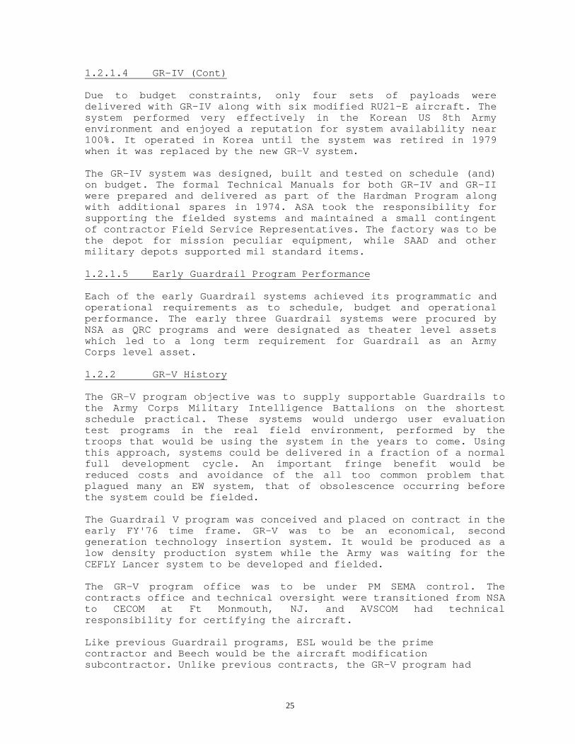
1.2.1.4 GR-IV (Cont)
Due to budget constraints, only four sets of payloads weredelivered with GR-IV along with six modified RU21-E aircraft. Thesystem performed very effectively in the Korean US 8th Armyenvironment and enjoyed a reputation for system availability near100%. It operated in Korea until the system was retired in 1979when it was replaced by the new GR-V system.
The GR-IV system was designed, built and tested on schedule (and)on budget. The formal Technical Manuals for both GR-IV and GR-IIwere prepared and delivered as part of the Hardman Program alongwith additional spares in 1974. ASA took the responsibility forsupporting the fielded systems and maintained a small contingentof contractor Field Service Representatives. The factory was to bethe depot for mission peculiar equipment, while SAAD and othermilitary depots supported mil standard items.
1.2.1.5 Early Guardrail Program Performance
Each of the early Guardrail systems achieved its programmatic andoperational requirements as to schedule, budget and operationalperformance. The early three Guardrail systems were procured byNSA as QRC programs and were designated as theater level assetswhich led to a long term requirement for Guardrail as an ArmyCorps level asset.
1.2.2 GR-V History
The GR-V program objective was to supply supportable Guardrails tothe Army Corps Military Intelligence Battalions on the shortestschedule practical. These systems would undergo user evaluationtest programs in the real field environment, performed by thetroops that would be using the system in the years to come. Usingthis approach, systems could be delivered in a fraction of a normalfull development cycle. An important fringe benefit would bereduced costs and avoidance of the all too common problem thatplagued many an EW system, that of obsolescence occurring beforethe system could be fielded.
The Guardrail V program was conceived and placed on contract in theearly FY'76 time frame. GR-V was to be an economical, secondgeneration technology insertion system. It would be produced as alow density production system while the Army was waiting for theCEFLY Lancer system to be developed and fielded.
The GR-V program office was to be under PM SEMA control. Thecontracts office and technical oversight were transitioned from NSAto CECOM at Ft Monmouth, NJ. and AVSCOM had technicalresponsibility for certifying the aircraft.
Like previous Guardrail programs, ESL would be the primecontractor and Beech would be the aircraft modificationsubcontractor. Unlike previous contracts, the GR-V program had

26
formal data requirements that included logistic engineering, aqualification test program, a formal integrated system testprogram, a parts program, a Mil std 45208 QA program, a governmentQA representative, mil std manuals including dash 10 dash 13 anddash 23 TM's, RPSTLs, formal software documentation andprovisioning. ESL provided a formal one time training program oneach system for the mission equipment and BAC provided airframetraining.

27
1.2.2 GR-V History (Cont)
The GR-V system was type classified as a Limited production urgent(LP-U) system. The system was nomenclatured as the AN/USD-9Special Purpose Detecting System. The GR-V system was designed anddocumented so it could be maintained by Army 33-S personnel withGR-V specialty training.
The overall GR-V program required 24 aircraft. These were derivedfrom the various versions of existing RU21 aircraft including theRU21-E, A, D and the G utility aircraft. Each of the aircraft weremodified to the GR-V specific RU21-H configuration shown in figure1.2.2-1. These aircraft would be outfitted with wing tip pods thatreplaced many of the individual antennas and had provisions forthe ALQ-44 and ALQ-36 radar warning equipment, had low reflectivepaint, and the were equipped XM-130 chaff and flare dispensers.Lighter, smaller DF equipment helped make room for the heavy UHFlink and RF antenna multiplexing equipment that was required inorder to connect multiple communications transceivers and on-boardradios to the same antenna.
The GR-V system employed three 40 ft sea-land type trailers tohouse the IPF illustrated in figure 1.2.2-2. The inside of theIntercept/DF van is shown in figure 1.2.2-3. The vans weremodified with operator stations and sealed for EMI integrity. TheIPF was designed to be transported in C-141 or C-5A type aircraft.A new computer system with vastly increased memory and processingcapability was introduced. The capability for direct transfer ofDF file LOP data into a
tactical report was also introduced. Computer assisted diagnosticsand link frequency algorithms were some of the refinements thatwent into the GR-V system software. More streamlined DFcalibration and built-in automated DF accuracy test software wasadded. Superior DF performance was available from this 2ndgeneration DF system that used two channels for successful DFagainst SSB and other intermittent signals.
The initial GR-V system was delivered in 28 months, on scheduleand was successfully fielded to replace the prototype GR-II atGruenstadt. ESL and the US Government developing agency, with thecooperation of the gaining command performed an evaluation testprogram prior to final hand-off to the 7th Corps. Two additionalsystems were delivered to Korea and CONUS in one year intervals.Both the GR-II and GR-IV system were retired at this point. Theolder GR systems had been heavily used, and did not have equalperformance to the new GR-V system.
The Guardrail V system met all criterion for a successful programas to budget, schedule and its operational capabilities. A sparespush package and stock fund spares were delivered with the GR-Vsystem to support system readiness.

28
Although the GR-V system was still largely a manual system from amission operational standpoint, it has proven to be a verycapable, reliable system that has lived up to full expectationsand generally exceeded all its performance specifications. Thefourth GR-V system was diverted to support the Improved GuardrailV program, hence was not completed or fielded and the last threeRU21-H aircraft were canceled.

29

30

31

32
1.2.3 IGR-V History
A requirement that was placed on the Improved Guardrail V (IGR-V) program was to transition to apressurized aircraft for higher altitude missions. It also desperately needed increased INS reliability. TheASN-86 INS had proved to be the weak link in system availability. Navigation was key to the DF capabilityand was needed to insure that the aircraft would not drift across the boarder into enemy territory during peacetime missions.
Another "requirement driver" for IGR-V was the integration of the Interoperable Data Link (IDL) in supportof inter service interoperability. The interoperable link originated as a wide band microwave link designed bySperry Univac for the Air Force. The link had been upgraded over the years and had a number ofapplications with the armed services. For example, a Ku band version of this link was the basis for theCEFLY Lancer link. Guardrail product improvements to the link that established interoperability includeddual Ku/X band tracker operation, error encoding, bulk encryption, a wider band uplink, dual airborneantennas and enhanced link diagnostics. The IDL provided vastly increased Guardrail link capacity andadded anti-jam features. The introduction of the IDL also moved the link interference outside the band ofCOMINT signals which would significantly alleviate EMC problems.
The IGR-V program got underway late '81 with a contract for two systems destined for V Corps and VIICorps.
One of the Guardrail challenges was the high density airborne signal environment. The availability of newlydeveloped technology for managing the collected signal environment called for implementation of pre-planned product improvements that included the Fast DF that was jointly developed by ESL and the USAFand the ESL developed Signal Classification and Recognition (SCARS) equipment. The SCARS equipmentwas developed by ESL under its IR&D program. These available technologies allowed auto search, auto DF,area of interest (AOI) screening and an order of magnitude increase in DF through-put with greater emitterlocation accuracy.
Interoperability with the Air Force was an OSD/NSA mandated objective for IGR-V. Achieving thisrequirement was greatly facilitated by using the common data link and a common Fast DF technology.
The pressurized IGR-V RC12-D aircraft was derived from the RC12 utility aircraft by militarizing theavionics and cockpit and by integrating the Carousel IV-E INS. The C-IV-E is a the high accuracy version ofthe Delco inertial navigation system commonly used on the C141 and KC-135 aircraft. The C-IV-E is amilitarized version of a proven, reliable commercial navigation system. ESL contracted with BAC for theinstallation of the data link antennas and mission antenna arrays. Certification and qualification testing of theRC12-D was part of the IGR-V program.

33
1.2.3 IGR-V History (Cont);
Four vans were used to provide the IPF with some 23 operatorstations that were equipped with color graphics terminals.Frequency coverage of the DF system was expanded, and asignificant upgrade in software was provided to make all thepositions capable of doing any authorized computer relatedresponsibility. A greater degree of signal collection automationwas made possible by the integration of Fast DF and SCARSsubsystems. A more sophisticated message file was added forinteractive report generation. These DF and signal processingupgrades made IGR-V a more powerful system than its GR-Vpredecessor. IGR-V was truly a significant product improvementover the GR-V system.
Like pervious Guardrail programs, IGR-V achieved its schedule andbudget and performed in excess of nearly all of itsspecifications. The pressurized aircraft, the IDL and Fast DF wereparticularly successful. Interoperability was tested during systemintegration and field tested later in Germany. Highly successfuldeployments and field tests were performed at the 5th Corps 205thMI Battalion in Wiesbaden in Oct. '84 and at the 7th Corps 330thMI Battalion in Stuttgart the spring of '85. Both systems weresuccessfully deployed during Desert Storm.
Guardrail/Common Sensor is a 7th generation Guardrail productimprovement program. The major requirements for this P3I programincluded integration of the Advanced Quick Look (AQL) ELINT systemand the Communications High Accuracy Airborne Locations System(CHAALS). The objective was an integrated SIGINT capability thatwould permit the retirement of the aging Mohawk aircraft with itsQuick Look II ELINT system. The Guardrail/Common Sensor systemwould provide full SIGINT on a single platform and would addtargeting accuracy. Although the development of AQL and CHAALSwere on-going programs under separate contracts, the GR/CS programactually got underway 1st quarter FY '85.
Other GR/CS upgrades included receiver pooling, digital intercomand digital temporary storage recording (DTSR), a greater aircraftpayload capacity in order to carry the added subsystems, and thelarger ELINT pods. Integration of the highly accurate GlobalPositioning System (GPS) equipment into the airborne navigationsystem was needed to support the TDOA capability. The RC12-K withits larger PT-67A engine would become the new Guardrail/CommonSensor aircraft.
Due to schedule considerations, six D model aircraft were modifiedto a RC12-H configuration for Guardrail/Common Sensor system 3.System 3 was fielded in Korea to replace the aging GR-V systemwhich was in need of refurbishment and the 60's vintage RU21-H'swere not going to last much longer with the mission work loadbeing flown in that theater. This meant that although System 3 hadbeen tested with EDM AQL and CHAALS units, it was fielded withoutthese subsystems.

34
1.2.4 GR/CS Systems 3 & 4 Background (Cont);
Another upgrade to the Guardrail/Common Sensor system was theinclusion of 4 mission computers rather than 1 computer to handlethe COMINT, AQL and CHAALS loading and to provide a back-upcomputer. Two of the four computers would be to support the AQLand CHAALS ground processing, while the fourth would back-up anyfailure of the Main System Computer (MSC) or backup the ELINTcomputer. This feature added a lot of reliability to the system byeliminating some single point failures.
The AQL program started in 1984 and underwent ED testing in 1985.The ED models were integrated and tested on the System 3 and 4aircraft at ESL. The flight test program proved the AQL equipmentto be accurate and it provided timely ELINT reports. Thisapplication of ELINT on a multi platform system with combinedSIGINT capability was considered successful. Production AQL unitsbuilt by ESCO were integrated on system 4 in the 1992 time frame.
The CHAALS development program began back in 1972 as a jointArmy/Air Force initiative. IBM developed the coherent processingand emitter location capability while ESL developed the equalizedTime Difference of Arrival (TDOA) receiver. Initial programs inthe 1970's were the Emitter Location System (ELS) and the MiniELS. This led to an 1980 flight test of the Coherent EmitterLocation Test bed (CELT). CHAALS is a productized outgrowth ofthese programs. A Global Positioning System (GPS) was integratedinto GR/CS to achieve the required navigation accuracy for TDOA/DDmeasurements. Also, a third data link was necessary to supportthree aircraft missions that are required for the CHAALS TDOA/DDoperations.
New pods that could support both COMINT and ELINT simultaneouslywere developed for the Guardrail/Common Sensor platform along witha flight test and certification program.
Guardrail/Common Sensor System 3 was deployed to the Republic ofKorea Oct. 1988 on schedule. Guardrail/Common Sensor System 4deployment was delayed till the Spring of 1991 so that productionAQL and CHAALS units could be integrated and tested prior tofielding to the V Corps 1st MI Airborne Exploitation Battalion atWiesbaden to replace the original IGR-V.
Several QRC enhancements were checked out in Guardrail/CommonSensor system 4 prior to fielding, then fully integrated in thefield later in the year. These QRC upgrades added capabilitiesthat were shown to be operational shortcomings in the Iraqconflict in early '91. These included Lowband intercept, Upwardfrequency extension with programmed multi-channel demodulation,Special Radio Exploitation (SRE), a Proforma capability andintegration of a TIBS interface. Although not fully integratedinto the Main System Computer (MSC) software, these PC based QRCsoftware upgrades provided an important increased capability that

35
might well be needed for any re-deployment to support insurgenceor special operations around the world.
Another key post fielding QRC upgrade to GR/CS system 4 was theSmart File Cabinet/FasTrack "smart mapping workstation". This PIPemployed two Sparc SUN workstation terminals and successfully re-used and expanded, a very large
set of existing graphics software. It included ESL developed IR&Dsoftware for terrain mapping/mission planning as well asgeographic data
bases developed by the US Government that were necessary tosupport this important system enhancement. Eventually, TIBS wasinterfaced to these workstations to provide the system withexternal multi-sensor data.
Some minor impacts to the GR/CS System 4 schedule and fieldingwere experienced along the way due to the large amount of GFE.Integration of CHAALS and AQL presented some challenges, but theoperational goals of the program were achieved. Some fieldmodifications to the GFE ELINT software was required and someCHAALS support software for mission monitoring were deemed to benecessary post fielding upgrades.1.2.4 GR/CS Systems 3 & 4 Background (Cont);
The Guardrail/Common Sensor System 4 was delivered with eightplatforms. The ninth platform and its payload was held back tosupport flight certification for the RC12-N model aircraft with itsnew multi function display (MFD) that enhances the cockpit MMI; andwas also needed to support various "System 1" next generationproduct improvements.
The ever increasing advancements in computer technology havecompressed the cycles of hardware obsolescence to a couple ofyears. Processing power increases by an order of magnitude witheach generation, performance per $ increases even more rapidly.With this extra processing power, signal processing, data sorting,very wide band fiber optic buses, embedded training and all sortsof capabilities are now available to the Guardrail system.
International standards are coming on line to control and definecomputer interfaces. These standards along with software languagesthat include development standards, now make software reusabilitya reality. Since it is no longer practical to control the futureavailability of particular computer hardware, nor would one wantto limit system capabilities and speed by doing that, it becomesapparent that a different approach to avoiding obsolescence isrequired.
ESL, under IR&D, and on other joint programs, such as the advancedSIGINT Fireworks program, put forth two initiatives to resolve thatdilemma. The first, was the application of a real time tacticalsystem processing architecture that was based on use of

36
international standards and use of the seven layer, Ada protocol.The second technology advancement was the Advanced Tactical SIGINTArchitecture (ATSA) initiative that employs a "unifiedarchitecture" that is bus oriented and employs all Ada software ina shared asset payload. In this manner, the architecture and thesoftware standards become the basis for the system, not the vintageof computer hardware. As new computer and bus technology comesalong, so does the method of adapting to the established standards.As new languages come along, they will also be required to becompatible with Ada "objects".
1.2.5 GR/CS System 1 (Hybrid system) and GR/CS System 2 (ObjectiveSystem) Background Overview (Cont);
The new airborne distributed unified architecture shifts away fromthe traditional philosophy of integration of dedicated hardwaresubsystems with typically non-reusable software that is verydifficult to upgrade and that is usually not compatible to newgeneration computers. Rather ATSA uses shared assets andestablished standards to define all interfaces, hence becomes anopen system architecture that can accept capabilities from anyonewho follows the rules.
As Shown in figure 1.2.5-1, distributed, unified architecture isthe driver for the current Guardrail System Technology InsertionProgram. Onboard assets have bus structures that are bridged to theground facilities bus via the data link and are synchronized sothat signal data can be re-constructed whenever tasking requiresit. This figure illustrates the types of assets that reside onboardthe platforms, how the wide area networks connect all elements ofthe system, shows the assets that are normally located on theground and lists the various standards that are employed to achievethis revolutionary approach to a SIGINT system architecture.
System 1 provides the distributed processing IPF that is alsodownward compatible with older Guardrail payloads and the Air Forcesystem. System 1's payloads are identical to the GR/CS System 4except it has extended coverage, lighter weight intercept receiversand has an improved interference reduction system that is requiredby agile on-board avionics radios and the TRIXS Relay. The System1 program started in September '91.
System 2, on the other hand, focuses on a new on-boardarchitecture designed to deal with the evolving signal environmentand at the same time further reduces weight. Use of common modulesand Ada software from an on-going development program, formed thebasis for the new "Unified" Guardrail payload architecture. Thesystem 2 payload is designed around a wide band signal fiber optic"Data Flow" bus, an FDDI bus and a synchronization fiber bus. Thistechnology had been already designed and laboratory tested. Sharedgeneral purpose processors are being used to perform signalprocessing and on-board data base management. These modules useestablished standards (or) are participating in establishingstandards where they do not yet exist. The newest generation of

37
the Interoperable Data Link, CHALS-X and AQL ELINT are beingemployed in the system as are wide band, multi-channel tuners andactive antennas. Although ELINT equipment is not initiallyunified, it is moving toward that goal by integrating airborneELINT processing into the common, distributed processors. Thisphase II portion of the program started early calendar year '92,with major follow-up ECP's.
Other planned upgrades include embedded training, advanced smartmap sensor management support, automated multi level securityreporting, expanded proforma exploitation and integration of thethree channel CTT with its multiple interfaces and protocols.These protocols include compatibility with TRIXS, TIBS,TRAP/TADIXS-B It potentially can communicate via Satcom nets.
1.3 Program schedule
This section provides an overview of the preliminary Guardrailenhancement schedule. The on-going and planned programs focus onthe Guardrail objectives for supporting current and future Corpslevel Army SIGINT requirements. Events like the retirement (ortransfer to National Guard) of the GR-V systems, IOC deployments,planned field retrofits and retrofitting of major enhancementslike drop-on microwave receiver, Automated Proforma, CHAALSsupervisor console, Auto Multi-channel Reporting with upgradedaccreditation, Mission Management Enhancements, ASE upgrades,CHAALS/ELINT on-board processing, embedded training, expandedinteroperability, mmw, direct satellite relay and onboard ELINTprocessing enhancements are projected in a timeline schedule. Fullimplementation of some of these capabilities is dependent onavailability of production funding. A high level programmaticschedule is depicted in figure 1.3-1.
A chart showing the flow of program technology initiatives thatare drivers for the current distributed processing GuardrailCommon Sensor System 1 IPF and the full-up distributed, unifiedarchitecture being employed Guardrail Common Sensor System 2 isillustrated in figure 1.3-2.

38
Guardrail Distributed Architecture WithSIGINT Wide Area Network
Figure 1.2.5-1

39

40
2.0 System Description
2.1 System capability matrix
Table 2.1-1 tabulates most of the top level capabilities of GR-V,IGR-V and the GR/CS family of systems. This summary ofcharacteristics and capabilities starts at the system level thenshows payload, aircraft and ground processing subsystemcomparisons.
By using available technologies, the Guardrail capabilities haveevolved with each product improvement program to better handle thechanging threats and improve the system's capability to workeffectively in the difficult tactical signal environments.
These capabilities will be explained in further detail in thesubsequent subsections of section 2. Many of the capabilities thatare future planned enhancements and not yet in the program. Thereare others that are only best knowledge projections.
2.2 GR-V Description and capabilities ;
The AN/USD-9 Special Purpose Signal Detection Guardrail V Systemis designed to support the tactical commander's at the Corps leveland below with near real time communications intelligence.Traditionally, the system served a secondary mission to collectintelligence under the peace time tasking (PARPRO) missions. Thisproduct improvement program used available 1970's technology toproduce a reliable, effective system in about two years. Thesystem computer processing capability is mainframe oriented, itsoperation is primarily manual and the threats are COMINT singlechannel voice and multi-channel. The system has a 3 van IPF, 6ARF's and an AGE step van.
It employs 1, 2 or 3 remote airborne payloads in stand-off flighttracks to intercept and locate emitters of interest. Remotelycontrolled VHF/UHF intercept receivers are used to search outtactical threats. VHF DF locates ground based and airbornecommunication emitters.
GR-V uses mission configured GR-V RU21-H platform. The three vanIPF supports the mission operation with operator workstations andwith a computerized signal data base. GR-V is self contained inthat it has a full complement of STE and TMDE installed in AN/ASM-189 shelters and has auxiliary vans for spares and transportationof accessories such as the communications antennas used at theIPF. Figure 2.2-1 shows the GR-V system components and an overallillustration of the system level interfaces.
2.2.1 GR-V Description and Capabilities Summary
An unclassified version of the Guardrail V system levelcapabilities and performance characteristics at the system levelare tabulated in Table 2.2.1-1.

41

42

43
Table 2.1-1

44
Capability Matrix
Capability/Mission GR-V IGR-V GR/CS GR/CS GR/CS GR/CSEnhancements Sys #3 Sys #4 Sys #1 Sys #2 Notes
Universal Workstations No No No No Yes YesDistributed Processing No No No No Yes* Yes *Has gnd LAN/WorkstationsAda (as dominate language) No No No No Yes YesScalable configuration No No No No Yes* Yes* *2,3 or 4 van deploymentDigital terrain mapping No No Yes Yes Yes YesSmart Map/Sensor Mgt No No Yes Yes Yes YesSIGINT overlay No No No Opt Opt OptCOMINT Yes Yes Yes Yes Yes YesELINT No No No Yes Yes YesReceiver pooling No No Yes Yes Yes YesFast DF/SCARS No Yes Yes Yes Yes Yes* *Embedded in ATSAUnified A/B Architecture No No No No Opt* Yes *RetrofitableOn-board ELINT processing No No No No No OptHigh resolution DF No No No Yes Yes YesSpecial signals No Yes Yes Yes Yes YesNumber of IPF vans 3 4 4 4 2,3,4 2,3,4Number of operators 19 23 26 26 25 25Platforms/mission 1,2,3 1,2 1,2 1,2,3 1,2,3 1,2,3Platforms, total aircraft 6 6 6 9 12 12Reporting TCT ICTT ICTT CTT* CTT CTT-h *RetrofitCollateral reporting No No No Yes* Yes* Yes* *"Air gap" ManualInteroperablity No Yes Yes Yes Yes YesWideband Microwave link No Yes Yes Yes Yes Yes* Multi Role Data LinkSeparated deployment opt Yes No No No Yes Yes* *Satellite relay (P3I)Data Distr System/MLS No No No Opt* Yes Yes *RetrofitProgrammable payload No No No No No* Yes *Requires RetrofitGateway bridge No No No No No* Yes *Requires RetrofitDistr on-board processing No No No No No* Yes *Requires RetrofitReceivers per mission 12 28 28 42 42 30* 30 set-on plus 24 WBReceivers per A/C (Max) 6 14 14 14 14 10* *10 set-on plus 8 WBExpanded band rcvrs No No No Yes* Yes Yes *QRC expansionBasic full COMINT coverage Yes* Yes Yes Yes Yes Yes *Except DFExtended upward coverage No No No Yes* Yes* Yes* *Intercept onlyExtended downward coverage No No No Yes* Yes Opt *Intercept onlyLPI No No No Opt Opt YesFDDM Yes Yes Yes Yes* Yes* Yes* *On-board and gndPCM/TDM No No No No No OptProforma No Yes Yes Yes Yes YesSRE No No No Yes Opt OptSignal recigizer on-board No No No No Opt YesDOA DF (multi chan vs 2 chan) 2 2 2 2 2 6DF extended coverage, down No No No No yes Opt*DF extended coverage, up No No No no Opt YesTDOA (ELINT & COMINT) No No No Yes Yes Yes

45
Table 2.1-1Capability Matrix (Con't)
GR-V IGR-V GR/CS GR/CS GR/CS GR/CSEnhancements Sys #3 Sys #4 Sys #1 Sys #2 Notes
ELINT, basic No No No Yes Yes YesELINT drop-on rcvr No No No No No* Opt *Requires Unified archELINT, Embedded No No No No No* Opt *Requires Unified archELINT, on-board proc No No No No Opt OptLink, air to gnd UHF IDL IDL IDL IDL GDDLLink, air to air Yes No No No No OptMessage transponder TCT ICTT ICTT CTT* CTT CTT *RetrofitSatellite remoting Yes No No No Yes OptFlight Line Support AGE AGE AGE AGE AGE Blt-in* *Built-in Go, No-go + AGE

46
2.2.2 GR-V IPF
The GR-V Surveillance Information Processing Center AN/TSQ-105(V)(IPF) is installed in three sea-land type transportable operatorvans. Figure 1.2.2-2 is a photo of the IPF with its antennas.Within the IPF, are the mission operators, the main systemcomputer (MSC)/special processors which provides the control,processing functions, message formatting capabilities. Supportingfunctions include links/communications/test functions. Alltogether there are 20 operator terminals in the IPF and normallyup to 19 operators. The IPF is configured with passage ways,egress, security, and support equipment. Figure 2.2.2.-1 shows aplan view of the IPF operator vans.
Figure 2.2.2-2 is a functional diagram of the GR-V IPF.
2.2.2.1 Analyst Van
Van 1 has eight operator positions. Two are DF Analysts withgraphics terminals. They have access to the system intercom andTCT voice communications. They are the senior analysts and haveresponsibility for the GR-V intelligence product and missionplanning.
The DF Location analysts work the DF files created by theIntercept/DF operators. They contain collected DF LOB's and thelocation of intercepted threats. The location analysts can alsocreate their own files using collected data from other DF datafiles. They use both computer maps, and transparency overlays onwall maps to establish battlefield situations and targets. Thelat-long or UTM coordinates with a EEP confidence major-minor axisdata is used in the formation of TACREPS. This data can betransferred into the report using the computer.
The three Traffic Analysts that are configured with recorderplayback, time code readers, a computer terminal andintercommunication and audio distribution equipment. Three alpha-numeric computer terminals support the Traffic Analysts in doingtext type analysis on voice information. Inputs to the Trafficanalysts come via manual gisting, location data from the Locationanalysts and from reel-to-reel recorders. The responsibility ofthe Traffic analysts is to reduce the collected data to TACREPmessage traffic as quickly as possible in preparation fortransmission to the tactical commander and other intelligenceconsumers. The fourth alpha-numeric position is the TacticalCommunications Operator (TCO). This position actually sends thecomputerized TACREPS via the TCT after they are reviewed andreleased by the Mission Managers. The TCO position has the TCTaccess, a printer for journalizing the release reports and thepaper punch machine. Released reports are also logged in the MSC.
The IPF power distribution/line filtering also reside in van 1.Wall maps and mission area information are available to themission personnel in van 1 and other vans. Van 1 is the main

47
entrance to the GR-V IPF and the center for intelligence productoutput activity.

48
GR-V System Concept
Figure 2.2-1
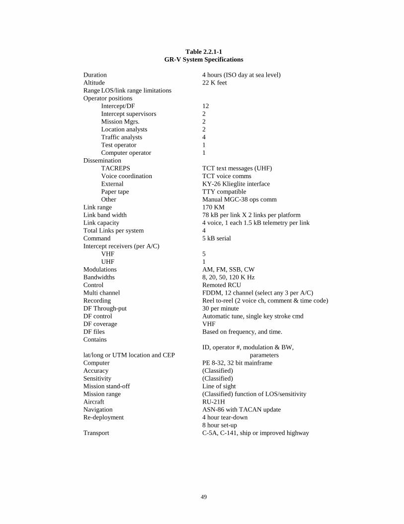
49
Table 2.2.1-1GR-V System Specifications
Duration 4 hours (ISO day at sea level)Altitude 22 K feetRange LOS/link range limitationsOperator positions
Intercept/DF 12Intercept supervisors 2Mission Mgrs. 2Location analysts 2Traffic analysts 4Test operator 1Computer operator 1
DisseminationTACREPS TCT text messages (UHF)Voice coordination TCT voice commsExternal KY-26 Klieglite interfacePaper tape TTY compatibleOther Manual MGC-38 ops comm
Link range 170 KMLink band width 78 kB per link X 2 links per platformLink capacity 4 voice, 1 each 1.5 kB telemetry per linkTotal Links per system 4Command 5 kB serialIntercept receivers (per A/C)
VHF 5UHF 1
Modulations AM, FM, SSB, CWBandwidths 8, 20, 50, 120 K HzControl Remoted RCUMulti channel FDDM, 12 channel (select any 3 per A/C)Recording Reel to-reel (2 voice ch, comment & time code)DF Through-put 30 per minuteDF control Automatic tune, single key stroke cmdDF coverage VHFDF files Based on frequency, and time. Contains
ID, operator #, modulation & BW, lat/long or UTM location and CEP parametersComputer PE 8-32, 32 bit mainframeAccuracy (Classified)Sensitivity (Classified)Mission stand-off Line of sightMission range (Classified) function of LOS/sensitivityAircraft RU-21HNavigation ASN-86 with TACAN updateRe-deployment 4 hour tear-down
8 hour set-upTransport C-5A, C-141, ship or improved highway

50
GR-V IPF Layout
Figure 2.2.2-1

51
2.2.2.2 Communications/Computer Van

52
Van 2 has the link, the communications, the encryptors, the mainsystem computer (MSC), the MSC printer, a hard copy graphicscopier, and the test support and mission flight coordinationfunctions. This equipment is shown in figure 2.2.2.2.-1. Van 2also has four of the 12 Intercept/DF Operator stations (exceptthese four positions do not have SDU's). Links and communicationsuse AN/ARC-164 UHF transceivers except for the down link. The downlink employs the ARC-176 multi-channel UHF communications set.ARC-176 receivers and Demux's receive and demodulate encryptedsignals from the ARF. The down link signals are distributed to allthe other positions via the Audio Distribution System. DF andIntercept Commands are formulated in the computer and RCU's. Thisserial data command and control data is transmitted to the ARF'sby the Command ARC-164 UHF radio. KG-30 series key generatorencryptors are used to secure the data links/command and control.KY-58's are used for voice and TCT communications. Van 2 has twoterminals that support the test operator. These are used alongwith link monitoring equipment and other test support equipment toinsure the proper system operation and to communicate with thepilot. Functions of the test operator position include:
- Mission initialization- IPF self test/pre-mission loop around tests- Mission launch and mission monitoring of airborne and IPF
health- VOW communications- Changing of mission configuration and ARF designator- Keying, zeroizing and storing of encryptors- Monitoring of the MSC- Mission shut-down and logging of any problems
The self test capability in the GR-V IPF generally employs commonmission equipment interconnected via special equipment usingmanual and computer controlled tests. Some units such as the RCUhave built-in diagnostic self tests.
2.2.2.3 Operator Van;
Van 3 is generally designated as the Operator van. A photo of thevan 3 operator positions is shown in figure 2.2.2.3-1. It has atotal of ten positions which include two Operator Supervisors withAlpha-numeric terminals. The Operator Supervisors also operate thesystem intercom and play a strong role in minute by minute missioncoordination/operator tasking and assist the Intercept/DFoperators in understanding the events as they unfold. Theremaining 8 positions are Intercept/DF operators. Each has accessto a payload receiver, SDU and DF equipment via their RCU and thecomputer terminal. Figure 2.2.2.3-2 is a photograph of theIntercept/DF position. The Intercept/DF operator has access to arecorder, intercom/signal distribution and a time code generator.Positions 4 and 8 have access to an on-board multi-channel SpecialPurpose Demultiplxer (SPD) capability. The responsibility of theIntercept/DF operators is to search out the threats assigned tothem and work any other incidental signal of value in their bands

53
and to do rapid identification, DF, gisting and recordingoperations.

54
Communications/Computer Position
Figure 2.2.2.2-1

55
2.2.2.3 Operator Van (Cont);
When adequate data is collected the mission mangers/supervisorsare informed and the DF files are passed via the MSC. The operatorsupervisors may also listen in and the location analysts canmonitor the DF files as they develop (and) request further follow-up data from the Intercept/DF operator on the task. Recorded andhand written information is passed to the Traffic Analysts.
Other support equipment in van 3 included the calibration DF testsynthesizer and DF test transmitter, Signal Distribution unit, andexternal interfaces used for extended system operation and specialoperations.
Each of the IPF vans has its climate control. Dual air-conditionsprovide cooling and heat for the equipment the operator personnel.Lighting, emergency exits, alarms, rifle racks etc are part of theIPF equipment.
The IPF has several communications and test antennas that must beinstalled such as to minimize interference and adjusted to aheight provide the coverage in the assigned mission area. The layout of the IPF is defined in section 2.2.6. Line of sight to themission platforms is essential for mission operation. The IPFoperator van site must be level with-in the tolerances of theleveling jacks that are part of the undercarriages. Theinstallation site must be level within approximately plus/minusone foot over a 50X50 foot area. Security lights are provided asare generators for mission power. The GR-V IPF can operate from 60Hz commercial power or conditioned 50 Hz or from 95 kW generators.A 10 kW generator is sufficient for auxiliary (mission-down)power.
System installation, life support and manning of the GR-V IPF iscovered in the system technical manual.
2.2.3 GR-V ARFs;
The Radio Receiving Sets AN/ARW-83(V3) commonly called theAirborne Relay Facility (ARF) include the GR-V sensors thatcollect signals and perform DF's against targets of interest andsupporting equipment. Figure 2.2.3-1 is a photograph of the GR-Vaircraft and its payload installation. Figure 2.2.3-2 is box levelfunctional diagram of the GR-V ARF. The GR-V ARF missionelectronics are installed in Guardrail V designated RU21-Haircraft. The RU21-H has wing tip pod DF antennas, VHF and UHFblade antennas, cabling to support their interface to the missionelectronics, mission power and a cockpit enunciator thatinterfaces to the pilot and provides warning lights and themission active control. The modifications also include cockpitmodernization and the ASN-86 inertial navigation system. Themission racks fasten directly to seat rails. Figure 2.2.3-3illustrates the cabin mounted racks and their interfaces to theairframe. There are three ARF racks as shown figure 2.2.3-3. This

56
diagram shows the location and name of each of the rack mountedunits.
There is an antenna control unit and conformal antennas in thepod. The direction finding antenna arrays are configured toprovide unambiguous direction finding, collection sensitivity andminimization of cross-interference.

57

58
Intercept/DF Operator PositionFigure 2.2.2.3-2
2.2.3 GR-V ARFs (Con't);
The ARF LRU's are typically ATR chassis that have been qualifiedfor airborne applications. Very few of these units came directlyfrom the previous Guardrails however the receivers are common toTrailblazer, and the DF equipment is similar to Trailblazer, the

59
Air Force and other similar systems. The link is an upgradedversion of the GR-IV UHF link. ARF equipment is grouped intolink/communications equipment, DF equipment, intercept equipment,TCT relay, power control/distribution, and VOW comm's. The unitswithin each of these subsystems are shown in table 2.2.3-3.Supporting equipment such as the aircraft mounted antennas, VOWencryptor and antenna control/cables that are installed as part ofthe airframe. Mission specific cable assemblies are used tointerface the ARF electronics and the aircraft. The DF cabling isphase sensitive and is phase matched at the factory to thetolerances required. This process make the airframe less sensitiveto changes in line replaceable units.
2.2.4 Aircraft
The GR-V RU21-H aircraft is derived from the RU21-G Army utilityaircraft or other older mission aircraft such as the RU21-E, A orD airframes. The GR-V RU21-H is upgraded with high flotationlanding gear for a 10,200 gross max. weight limit. The aircraft iscertified with wing extensions/pods and the other mission airframemodifications. Two 200 amp generators and extra 400 Hz inverterssupport the mission electronics and avionics. Twenty one of theGR-V RU21-H aircraft exist. Figure 2.2.4-1 shows the aircraft andits antenna configuration. The location and function of eachappendage is also shown.
The mission enunciator panel located on the aircraft instrumentpanel has the Mission Active switch and indicator lights to warnthe pilot of mission faults such as over temperature, loss of linksynchronization and processor lock-up. The ARF Status panellocated on the mission racks behind the co-pilot that shows moredetailed mission parameters and has the ARF (1, 2 or 3) designatorcontrol. As with other GR systems, the crews responsibility isonly to fly the aircraft and to monitor the health of the missionequipment. (Most of the ARF parameters are also monitoredremotely, but only the crew can activate or re-cycle the missionequipment.)
2.2.5 GR-V AGE;
Flight line support for the GR-V payloads is provided by theAN/ARM-163(V)3, commonly called the AGE. The AGE electronics ismounted in a step van that has auxiliary power and is fullymobile. It has all the controls, link interfaces and displaysnecessary to command the intercept and DF subsystems, to monitortheir return signals and to do loop around link tests required toassure a successful mission. The AGE is also a diagnostic tool fortrouble shooting the ARF electronics. The AGE is linked up to theARF but can also be connected directly with cables. Test signalsare likewise radiated, but can be connected for more preciseroutine maintenance testing.

60

61
GR-V Aircraft and Payload
Figure 2.2.3-1

62

63

64

65
2.2.6 Tactical Commanders Terminal (TCT);
The An/TSC-87 Tactical Commander's Terminal receives relayedmessage data from the GR-V IPF via the ARF. These reports areprinted out by the TCT for use of the tactical commander. The TCTalso has half duplex voice communications used for coordinationand re-tasking of the system. KY-58 encryptors are used to securethe TCT links. Figure 2.2.6-1 is a photograph of the TCT fieldterminal.
2.2.7 GR-V Satellite Remote Relay;
The GR-V system has available a Transportable Relay Facility (TRF)that enables relay of the system links via a TSC-93 earth terminalthrough the DSCS III communications satellite. It also has a hilltop repeater to extend the range from the platform to thetransportable relay facility (TRF). Figure 2.2.7-1 is aoperational diagram of the GR-V satellite relay. The IPF requiresan earth terminal and an interface subsystem installation tooperate in the relay mode. All GR-V subsystem nets i.e. data links1-4, command, VOW, TCT are multiplexed and fiber optically linkedto the earth terminals at the remote site and IPF location.Interface hardware installed in the system allows GR-V to operatein either the local or remote mode. The TRF is installed in an S-280 shelter with mobilizes. The entire remote subsystem istransportable in a C-130 aircraft and TRF including the hill-toprelay equipment is helicopter lift able. Two of the GR-V systemshave satellite relay capability.
2.2.8 Interference Mitigation;
A critical parameter in the GR-V system is its communicationsfrequency allocation requirements. Avionics transceivers operatein the VHF and UHF bands as does the mission sensors and themission communications links. Up to five mission transceiversconnect to a single communications antenna. Although some of thecommunications links only transmit intermittently, there is greatpotential for interference.
The intercept subsystem has a high dynamic range RF distributionunit and notch filters to help protect it from on-boardinterference. Special filters and RF multiplexers in the avionicsand the mission equipment are used to reduce splatter and toprotect the radios from potential adverse RFI/EMC affects. Theseinclude a tracking filter in the pilots UHF radio, notch filtersin the avionics and the RF multiplexers in the UHF link antennapath.
In addition to these hardware interference protection devices,further precautions are required. GR-V frequency allocationmanagement, which is an off-line computer program, suggests andvalidates the selection of mission communications frequencies forcommand, returned data links and TCT comms. The notch filters aretunable and are switched in when needed. The UHF mux's track the

66
attached transmitter or receiver. The procedures and the limitsprescribed must be carefully adhered to in order to avoid directinterference or interference from products generated betweeneither airborne or ground communications. Spacing and orientationof antennas on the ground with its filtering protects the IPFsite. Interference between GR-V and other adjacent facilities mustalso be considered.

67
Tactical Commanders Terminal
Figure 2.2.6-1

68

69
2.2.8 Interference Mitigation (Con't);
On-board the platform the problem is much more critical because ofits close proximity to the antennas, and there are strictrequirements for aircraft safety. Further, the mission interceptand DF sensors must share the same physical space and frequencybands. The system is effective when the design parameters andstandard operational procedures are adhered to, howeverinterference mitigation is a critical system requirement tomaximize performance.
2..2.9 GR-V Employment;
Guardrail V is a CONUS based COMINT system that is part of theArmy worldwide EW forces. It provides airborne, stand-offcollection and location of tactical communications signals. Re-deployment requires advance preparations or at least an advancedparty to consider the best location and to insure that line ofsite to the planned mission flight tracks has been properlyconsidered. The system requires approximately a 200 ft by 200 ftarea for the IPF and a landing strip within range of the plannedmission flight tracks.
2.2.9.1 Site Preparation and IPF Installation;
Figure 2.2.9-1 illustrates the site layout and spacing of thecommunications antennas. The overall planning is included in thesystem manual.
Items to support such a move include camouflage, spares,consumables such as tapes, disks and rations, water, fuel, ammoetc.
Mission initialization sets up the parameters that are standardfor a mission or are peculiar to the mission or to the theater ofoperation. These procedures include bringing the computer up,entering the IPF location, entering maps of the new mission area,crypto keying, setting up the communications frequencies,determining of areas of interest, establishing search scenarios,and entry of applicable archived a-priori data etc.
IPF pre-mission test is part of initialization unless is wasalready done (this is particularly important if the system hasbeen fully shut down or moved.)
Numerous details are involved for mission implementation. Theseinclude personnel briefings, scheduling, flight operationsplanning, coordinating and establishing of mission flight trackprofiles, defining of mission objectives/tasking, identificationof threats, etc. A correct understanding of the mission area andits terrain along with the priorities for optimization of systemperformance, is essential to planning system initialization andsetting up flight orbits that will insure target field of view(FOV).

70
A specific procedure defined in the system technical manual mustbe followed during mission shut down in order to summarize themission data, store it in archives or retain it as a-priori datafor the next mission. It is also important to insure an orderlyshut down of the application software. At the close of eachmission attention should be given to any problems that may haveoccurred during the mission. Debriefing of operator andmaintenance personnel is part of the mission shut down procedure.Normally the computer equipment and climate control system will beleft running for the next mission. Off-line analysis work andtraining normally occurs between missions.

71
2.3 IGRV Description and Capabilities;

72
As shown in figure 2.3-1, the IGR-V mission concept is similar toGR-V. The AN/USD-9(A) Special Purpose Signal Detection Systemcommonly called the Improved Guardrail V (or) IGR-V, is a fifthgeneration Guardrail system that employs updated data link, DF, andsearch and acquisition technology. Major product improvementsimplemented in IGR-V with respect to GR-V are:
o Pressurized RC12-D aircraft with upgraded cockpit,power systems, ASE, mission antenna arrays and 14,200gross weight. Includes certification ofairframe/qualification testing.o High reliability Carousel IV-E inertial navigation system.o Integration of the Interoperable Data Link (IDL). Includes PIP'sto IGDL, AIDL and GSE that resulted in a common Army/Air Forcemicro wave data link operating in Ku Band and with dual bandtracker upgrades.o Army/AF Common Fast Direction Finding (FDF). Increasedthrough-put and expanded frequency coverage to include fullVHF/UHF. Includes on-board LOB processing and groundlocation processing.o Auto search via signal classification and recognition system(SCARS). Includes Directed search, general search, signalrecognition/classification and area of interest screening.Also triggers automatic DF.o Improved primary field of view emitter location accuracy,via improved antenna aperture.o Up-graded main system computer (MSC) with color graphic operatordisplays, message files, joint service report generation and selftest and computer diagnostics to support the new technologyinsertions.o Next generation of VHF/UHF receiverso Biological/chemical protection for operator vanso Improved reporting capability with the dual channel ICTTfield communications terminal and message prioritization.(The ICTT interface unit in the IPF is downward compatiblewith the TCT field terminals and the TCT airborne relay.)
The Improved Guardrail-V system employs the new generationConcurrent 3252 main frame computer with expanded semi conductormemory and multi disk drives and re-uses as much GR-V software aspractical. The color terminals use digital color graphicstechniques vs. the GR-V "memory scope" type display for graphicsso that all terminals are compatible and any or all computerfunctions can be allocated to an operator and can be supportedfrom any operator position. The computational speed increased anorder of magnitude as did memory capacity. Array processors using68000 chips were added to both the airborne system and the groundequipment for high speed processing of the collected FDF AOI andSCARS signal activity/recognition data.
Table 2.3-1 provides a tabulation of the IGR-V system levelspecifications.

73

74
Table 2.3-1
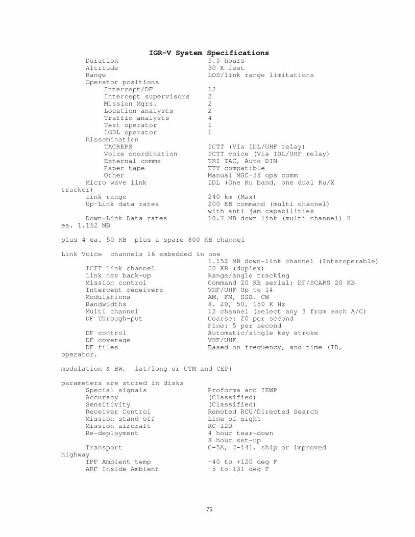
75
IGR-V System SpecificationsDuration 5.5 hoursAltitude 30 K feetRange LOS/link range limitationsOperator positions
Intercept/DF 12Intercept supervisors 2Mission Mgrs. 2Location analysts 2Traffic analysts 4Test operator 1IGDL operator 1
DisseminationTACREPS ICTT (Via IDL/UHF relay)Voice coordination ICTT voice (Via IDL/UHF relay)External comms TRI TAC, Auto DINPaper tape TTY compatibleOther Manual MGC-38 ops comm
Micro wave link IDL (One Ku band, one dual Ku/Xtracker)
Link range 240 km (Max)Up-Link data rates 200 KB command (multi channel)
with anti jam capabilitiesDown-Link Data rates 10.7 MB down link (multi channel) 8
ea. 1.152 MB
plus 4 ea. 50 KB plus a spare 800 KB channel
Link Voice channels 16 embedded in one1.152 MB down-link channel (Interoperable)
ICTT link channel 50 KB (duplex)Link nav back-up Range/angle trackingMission control Command 20 KB serial; DF/SCARS 20 KBIntercept receivers VHF/UHF Up to 14Modulations AM, FM, SSB, CWBandwidths 8, 20, 50, 150 K HzMulti channel 12 channel (select any 3 from each A/C)DF Through-put Coarse: 20 per second
Fine: 5 per secondDF control Automatic/single key strokeDF coverage VHF/UHFDF files Based on frequency, and time (ID,
operator,
modulation & BW, lat/long or UTM and CEP)
parameters are stored in disksSpecial signals Proforma and IEWPAccuracy (Classified)Sensitivity (Classified)Receiver Control Remoted RCU/Directed SearchMission stand-off Line of sightMission aircraft RC-12DRe-deployment 4 hour tear-down
8 hour set-upTransport C-5A, C-141, ship or improved
highwayIPF Ambient temp -40 to +120 deg FARF Inside Ambient -5 to 131 deg F

76
2.3 IGRV Description and Capabilities (Con't);
IGR-V has approximately an order of magnitude increased DFthroughput and computer capacity. Its ability to search outtargets of interest and automatically locate them is a keyupgrade. Use of the Interoperable data link and the common fast DFsystem provides interopability with an Air Force system. Theability to get higher altitudes and a longer range data link givesthe system greater coverage and the pilots no longer need to wearoxygen masks during the mission.
Figure 2.3-2 is a functional block diagram of the IGR-V system.
2.3.1 IGRV IPF;
The IGR-V Surveillance Information Processing Center AN/TSQ-105(V)4 (IPF) is installed in tempest/NBC sea-land typetransportable operator vans. The IGR-V IPF employs a four vancomplex with a total of 23 operator stations. The shelters havepositive pressure, entry vestibule, filtration of air and alarmsystems for NBC protection. In addition to the operator vans, IPFsubsystem includes the power distribution vans, the IGDL Trackers,the maintenance support van and test antennas/backup VOW antenna.Figure 2.3.1-1 is a functional diagram of the IGR-V IPF. Figure2.3.1-2 is a pictorial drawing of the IPF site. Figure 2.3.1-3 isplan view of the IPF operator vans. Figure 2.3.1-4 shows thephysical van configuration. The side view in this figure shows theNBC filter system and the entry vestibule.
Van 1 has 8 positions.
- Two Mission Managers with large screen 21" terminals andaccess to internal and external ICTT voice communications.
- Two Location Analysts with access to the ICTT and voicechannels the same as the Mission Managers.
- Four Traffic Analysts with 13" terminals, recorders forplayback and access to comms. One of the Traffic Analysts isthe tactical operator and has the ICTT interface and printerfor a record of message transmissions.
The van 1 likewise has tactical area maps, ICTT printer forlogging message traffic, and control of the TACREP messageinterface at one of the traffic analyst positions. Van 1 also hasthe power distribution and the MSC printer.
Van 2 has the Main System Computer (MSC), the IEWP, and workspace/expansion space for operator positions.
Van 3 has the communications facility with the test operator andfour of the 12 Intercept/DF Operators. The IDL, VOW, ICTT commsand the system monitoring equipment reside in this van.Encryptors, Auxiliary comms, and mission initiation/diagnosticsare part of van 3. The test operator's responsibilities are:

77
- Power-up/pre-mission test and initialization of computersystem.
- Start-up and readiness test of the IGDL (initialization andloop around test).
- Manage the interactive test of the various hardware equipmentin the IPF and do VOW, ICTT, data multiplexing loop-aroundtests.
- Communicate with the flight crew and monitor mission flightdata.

78

79

80

81
IGR-V IPF Interior LayoutFigure 2.3.1-3

82

83
2.3.1 IGR-V IPF (Cont);
Van 4 is the operator van. There are 8 Intercept Operators and twoSupervisors in this van. The operators have the followingequipment to support the collection, file generation and emitterlocation responsibilities:
- Computer terminal- Supports tasking assignments; creation of afile to enter data; signal identification, provides key strokeDF control; manages stored collected DF data that includesauto storage of parameters such as frequency, modulation andband width; and other on-line functions.
- RCU for controlling the on-board intercept receivers.- SDU for monitoring the spectrum in the region of tuning.- Time code for mission time and recorder synchronization.- Data distribution/Intercom headset and controls.- Reel-to-reel recorder with dual signal recording, comments and
time.
The van 4 equipment includes two Operator Supervisors positionswith computer terminals, system connectivity etc. These positionsalso have the Signal Distribution/ Intercommunications consoleswhich are controlled by the supervisors. The supervisors also haveRCU's and recorders. The DF test synthesizer/transmitter residesin van 4 along with some of the data demultiplexing, multi-channelfrequency division demultiplexing (FDDM) equipment and Proformaequipment.
2.3.2 IGRV ARF;
The Radio Receiving Sets AN/ARW-83(V)5 commonly called theAirborne Relay Facility (ARF) provide the IGR-V airborne sensorsthat collect signals and perform DF's against targets of interest.The IGR-V ARF mission electronics are installed in the ImprovedGuardrail V designated RU12-D aircraft. The RU12-D has wing tippod DF antennas, VHF and UHF blade antennas, fore/aft IADL dishantennas, cabling to support their interface to the missionelectronics, cockpit modernization, mission power/cockpitenunciator and mission active control and the C-IV-E inertialnavigation system. The two mission racks fasten directly to seatrails. Figure 2.3.2-1 illustrates the ARF components, gives theirnames and shows their interfaces to the airframe. The antennaarrays are configured to provide unambiguous direction finding,good collection sensitivity, link communications and areconfigured for the minimization of cross-interference.
Figure 2.3.2-2 is a simplified functional diagram of the IGR-Vpayload.
The primary mission of the ARF is the sensor for the IGR-V system.Sensors include the intercept equipment and the DF equipment. TheARF has provisions for 14 each R-2089 intercept receivers. Otherintercept equipment includes the antenna notch filter, RFDistribution, SDU Remote and SCARS 0 and SCARS 1/2 down converter.

84
The FDF equipment includes the RF Processor, R-2077 DF receiver,and the airborne DPU. These remotely controlled equipment'soperate in concert to collect signal and obtain lines of bearingto the emitters of interest.

85

86

87
2.3.2 IGR-V ARF (Cont);
Supporting equipment includes the communications and power system.IADL equipment has an executive processor, R/T, TWTA, waveguide/antennas and KG-45 COMSEC. Multiplexing equipment includesthe Command Demux and the Data Mux. The ICTT relay is TCTcompatible and includes 2 ARC-164 transceivers and RF filtering. Aairborne power supply, power distribution and a ARF status panelare provided to control and monitor the mission equipment. Anenunciator/control panel is located in front of the co-pilot toactivate the mission, monitor warning lights and control the IADLTWTA/antennas.
2.3.3 RC12-D Aircraft;
The IGR-V RC12-D special electronic mission aircraft is a modifiedversion of an RC12 utility aircraft. This pressurized dual seataircraft is powered by two UACL PT 6A41 turbo prop engines ratedat 850 SHP with Hartzell 3 blade, constant speed propellers aspictured in figure 2.3.3-1. The high accuracy version of the DelcoCarousel IV-E inertial navigation system is integrated into thisnear all weather aircraft. Antennas include "RU21-H like" wing tippods, plus a tail boom blade, dual microwave link antennas, and aUHF array. Avionics are updated with systems like the Sierra TACANDME for INS position updates, AP-106 auto pilot, ARC-186 radio,RT- 1167 (ARC-164) UHF radio, APN-215 color weather radar and anASE suite including the AN/APR-39, AN/APR-44 and the M-130 chaffand flare dispenser. The gross max capacity of the RC12-D is14,000 lbs. Figure 2.3.3-2 shows the aircraft configuration anddefines the location and usage of its avionics and missionantennas. The platform has reserve for future growth and is ableto exceed 25,000 ft altitude.
2.3.4 IGRV AGE Subsystem;
Flight line support for the IGR-V payloads is provided by theAN/ARM-163(V)4 commonly called the AGE. The AN/ARM-163 AuxiliaryGround Equipment provides complete flight line maintenance andtest for the ARF mission electronics. The AGE physicalconfiguration is shown in figure 2.3.4-1. It does loop around testof the communications and link equipment. Radiated signals andcommands are used to test the on-board Intercept and DF equipmentand software. The AGE uses a mini computer to formulate tests andrecord test results.
The AGE is installed in a 1 ton step van with auxiliary power forflight line operation. Direct routing of test signals via cableand test panel is provided as an alternate method of test when itis desirable not to radiate signals or when more exacting levelsare required. The AGE is also capable of self test/diagnosticswhich verifies the AGE equipment prior to preflight operations.Figure 2.3.4-2 is a functional diagram of the IGR-V AGE.

88

89

90

91
2.3.5 Interoperable Data Link

92
The Interoperable data link was developed by the Air Force andimproved by the Army for use on the IGR-V system. IGR-V uses twoIGDL Trackers shown in figure 2.3.5-1 for dual aircraft operation.The Trackers have 6 ft tracking dishes and house the TWTAamplifier, receiver and have built-in alignment and test supportfeatures.
Three racks of equipment in the IPF contain themodulating/demodulating, encoders, encryption, and computercontrol/diagnostic equipment. Each linkrequires one rack of equipment and the third rack supports builtin test and control functions.
The IDL interfaces to the mission multiplexers, demultiplexers andto the MSC. The data link provides back-up location updates to theINS.
Airborne IDL (IADL) equipment interfaces to the on-board missionData Multiplexers and Command Demultiplexers, and to the airframefore-aft antennas and to other IDL control interfaces that areinstalled by the airframe company. Power up and back-up antennacontrols are located on the instrument panel. Automatic switchingbetween the dual link antennas are tied to the navigation/IDLExecutive processor to give fore-aft coverage. The tail antennagives about 210 degrees of coverage and the nose gives plus minus90 degrees coverage. The link operates in the Ku band well outsidethe mission collection frequency band and has about 70 watts ofdown link power.
The link ground support equipment (GSE) is located in the AGE is asubset of the equipment in the IPF and ARF. It has both self testand loop around tests to initialize and check out the ARF IADLlink.
Figure 2.3.5-2 is an interface diagram of the ground based IDLequipment.
2.3.6 Improved Tactical Commanders Terminal (ICTT);
The AN/TSC-116 remote communications terminal supports thereception of dual relayed IGR-V tactical reports and has halfduplex voice communications. Each ICTT is equipped to receivesecure teletype messages from two sources at a time. One relaymight be the local Guardrail and the other may by from aneighboring Corps Guardrail or the Air Force. These TACREPmessages are buffered into the ICTT field terminal, checked forpriority and printed out or buffered into a host computer. Figure2.3.6-1 is a drawing of the ICTT field terminal installation andits interfaces.
The ICTT also has half duplex voice communications for tasking andchatter with other commanders. Since the ICTT is relayed from theIPF through the ARF, it has a range that extends well beyond the

93
normal line of sight. The ICTT has an antenna and encryptionequipment. It is mounted in carrying cases to protect it while intransit. Power is provided by the host unit.
Radios in the ICTT are ARC-164's and are secured by KY-58encryptors.

94

95

96
ICTT ApplicationFigure 2.3.6-1

97
2.3.6 Improved Tactical Commanders Terminal (ICTT) (Con't);
Figure 2.3.6-2 is a functional diagram of the AN/TSC 116 ICTT Terminal equipment. The ICTT has threemodes: The TCT compatible 300 baud mode, the mid rate 1 K baud rate and a 2K baud rate. Figure 2.3.6-2also illustrates how the IPF and ARF reporting interfaces and how reporting interop works.
The IPF ICTT message equipment is also downward compatible with the older AN/TSQ-87 TCT fieldterminal.
2.3.7 IGRV Employment;
Improved Guardrail V is a CONUS based COMINT system that is partof the Army worldwide EW forces. It provides airborne, stand-offcollection and location of tactical communications signals. Re-deployment of IGR-V needs to have advance preparations or at leastan advanced party to consider the best location and to insure thatline of site to the planned mission flight tracks has beenproperly considered. Although the system has organic support, itrequires an IPF installation area with tracker line of sight tothe flight tracks and a landing strip within range of the plannedmission flight tracks.
2.3.7.1 Site Preporation and IPF Installation;
A pre-planned order of entry to the new site will be necessary toinsure proper set-up. The order of march for convoy should be basedon the order of entry if possible. The actual order of arrival maybe driven by considerations that will vary from sited to site. TheSuggested order is IPF vans 1, 2, 3, 4, trackers, powerdistribution system, maintenance 189 van, 190 van and Aux. van.
Figure 2.3.7.1-1 illustrates the site layout and dimensions. Theoverall planning is included in the system manual TM 11-5865-243-10.
Items to support such a move include tractors, the NBC protectionfilters, camouflage, spares, consumables such as tapes etc andrations, water, fuel, ammo etc.
2.3.7.2 ARF/AGE Checkout Proceedures;
Proper check out procedures assures that the mission electronicsare properly installed in the aircraft, the aircraft is poweredup, INS is aligned and the mission electronics is activated. Thereare certain safety precautions such as microwave radiationperimeter/protection of personnel etc. The crypto equipment isinstalled and keyed to either the test code or the code to be usedon the mission, if the mission is to follow the checkout.
The AGE, after successful self test, is locked up to the missiondata link. Loop around tests demonstrate that the link isoperating correctly. The on-board intercept equipment is commandedto specific test scenarios. A low level radiated signal from theAGE is received and the response of the mission intercept is

98
monitored in the AGE. Like wise, the DF system is commanded andits response to its own test signal is monitored within the AGE.If the mission equipment is operating correctly and the platformis properly identified as an "ARF 1" or "ARF 2" and thecommunication/link frequencies are properly set-up the platform isdeclared mission ready. Abbreviated tests may be used for quickturn around or more extensive diagnostics may be used if there istrouble with the mission equipment.

99
ICTT Link InterfaceFigure 2.3.6-2

100

101
2.3.7.3 Mission Inialization;
Mission initialization sets up the parameters that are standardfor a mission, or are peculiar to the mission or to the locality.These include bringing the computer up, entering the IPF location,crypto keying, setting of communications frequencies, entering upto 16 areas of interest, establishing search scenarios, and entryof applicable archived a-priori data etc.
IPF pre-mission test is part of initialization if that has notbeen previously done (this is particularly important if the systemhas been fully shut down.)
2.3.7.4 Mission Deployment;
Numerous details are involved for mission implementation. Theseinclude entering the IPF coordinates into the computer, trackerlocations/bore sighting, entering mission maps into the computer,and reviewing mission tasking, personnel briefings, missionscheduling, flight operations, coordinating and establishing ofmission flight track profiles, defining of missionobjectives/tasking, identification of targeted threats, etc. Acorrect understanding of the mission area and its terrain,insuring link LOS, along with the priorities for optimization ofsystem performance, is essential to planning of systeminitialization and location of flight orbits that will insuretarget field of view (FOV).
2.3.7.5 Operator Responsibilities;
Mission ManagerEstablish mission goals and personnel tasking. Normally performedby a 98 C.
COMINT SupervisorThe COMINT supervisor positions are normally manned by senior 98Gs who have system experience and intercept experience. Their taskis to help individual operators and maintain the properenvironmental coverage. They verify that operators are notneedlessly overlapping and aid in passing signals to operators whomay be more experienced with certain types.
COMINT Intercept/DF OperatorThe intercept positions are manned primarily by 98 G's andsomewhat by 98 Ds. These operators are responsible for identifyingemitters, DF'ing recording and transcribing the audio or usingother equipment to perform signal analysis.
Traffic AnalystThe traffic analyst position is manned by a 98 C who isresponsible for sorting through the situation analysis data andgenerating the various report types which end users require.
Location Analyst

102
The location analyst function is performed by an 98 C who has theresponsibility to analyze the transcripted and DF data from theintercept/DF operators to determine the target area laydown andmovement of units.
2.3.7.5 Operator Responsibilities (Cont);
Tactical Communications OperatorThe TCO is a 98 C who is responsible for helping generate reportsand is also normally the final check for validity and security foroutgoing reports. This position is then responsible for selectingthe outgoing message path and transmitting the message.
Civilian Support PersonnelIn addition to assigned military personnel, most sites aresupported by civilian personnel who are specially trained to helpmaintain equipment and provide support to the unit operations.Examples of these contractor technical representatives (CTRs) areBASI support personnel who maintain the aircraft, contractorpersonnel who support the data link and government/contractorpersonnel who help to perform training on the prime missionelectronics.
2.3.7.6 Flight Tracks;
2.3.7.6.1 Flight Tracks For Single aircraft;
The system can operate effectively with only one aircraft. Ofcourse, there will be no instant DOA triangulation capability witha single aircraft. The flight track should simply be the baselinefrom waypoint to waypoint in as straight a line as possible. Thiswill provide for maximum coverage of the area of interest. It isalso possible to fly a "dog-leg" track , taking care that thecenter turn is under 45 degrees to avoid a blind area in thecenter of the track. The dog-leg track will allow for slightlyenhanced coverage of the center mission area, but the straightline leg for longer baseline is preferred. With a single aircraftthere is also more flexibility in the track distance and flightoperation since there are no turns to coordinate and the track canextend as far along the signal of interest front as desired.
2.3.7.6.2 Flight tracks For Dual Aircrft;
Normally, two aircraft are used on a mission. In this case,"canted" legs as shown in figure 2.3.7.6-1 is best, as it willprovide best coverage of the central area while allowing runningoptimum DOA fixes. If a longer baseline is required, the aircraftshould fly canted legs spread apart by about 50 to 75 km.
2.3.7.7 Missiion Shutdown;
103
A specific procedure as defined in the system technical manual,must be followed during mission shut down in order to safelysummarize the mission data, store it in archives, or retain it infiles as a-priori data for the next mission. To avoid loss of datait is important to insure an orderly shut down of the computer anddata link. Debriefing of operator and maintenance personnel ispart of the mission shut down procedure. Proper attention shouldbe given to record any problems that may have occurred during themission. The conclusion of a day's mission activity should befollowed up immediately with maintenance required to resolve anyproblems that might have occurred during the mission. Normally thecomputer equipment and climate control system will be left runningfor the next mission. Normally operator training and off-lineanalysis work occurs between missions.

104

105
2.4 GR/CS System 3 and GR/CS System 4 Description andCapabilities;
The AN/USD-9(B) Special Purpose Signal Detection System commonlycalled the Guardrail Common Sensor System (or) GR/CS is a combinedCOMINT-ELINT or "SIGINT" system. Guardrail Common Sensor is aproduct improvement to the IGR-V system. This section thereforewill define the upgrades and design changes with respect to thecapabilities of IGR-V and provide top level GR/CS systemdefinition and specifications. System 4 major enhancements includethe following:
o Integration of CHAALS for COMINT high accuracy TDOA/DD COMINTemitter location which providessupport to COMINT targeting operationso AQL for ELINT collection/emitter location/target processing andELINT TDOAo Receiver pooling for flexible allocation of intercept assetso Digital temporary storage recording (DTSR) and a digital audiobus for audio recording and audio distribution support to theoperator positionso SIGINT related software upgrades for combined for processing ofcombined COMINT/ELINT missions and for TDOA operator tasking.o Integration of GPS for highly accurate navigation updateso Re-engine, modified RC12-K aircraft with PT-67A engines,increased payload capacity/take-off climb margin required forSIGINT mission capacity. Includes new SIGINT wing tip pods.o Integration of third IDL for three platform ELINT and TDOA COMINTmissions
A number of upgrades related to these fundamental enhancements arealso a necessary part of the GR/CS program. For example GR/CSemploys four main frame computers Vs one computer in IGR-V, withintegrated software interfaces that are required between COMINT,ELINT and CHAALS. These computers and several new specialprocessors support the new SIGINT capabilities and precision timedifference of arrival (TDOA) emitter location capabilities andprovide the required additional processing power and storage tomanage the approximate additional 500K lines of code entailed inGR/CS.
Two different airframes were used for systems 3 and 4. The RC12-Hused on system 3 is a derivative of the RC12-D that is used forIGR-V. The reason for this variation hinged on the fact that theRC12-K could not be made available in the delivery time frame. TheRC12-H has the appearance of the RC12-K including the new pods,but has the smaller PT-6A-41 engines and a 15,000 lb gross maxweight limit.
The RC12-K GR/CS System 4 aircraft has larger engines and beefedup wings and additional empennage modifications for stabilizationand a 16,000 lb gross max capacity that is capable of carrying theadded CHAALS and AQL sensors.

106
The technology for many of the system upgrades such as TemporaryDigital Storage Recording (DTSR), GPS hardware, AQL and CHAALS camefrom other programs. For example, the DTSR came from an Air Forceprogram. This upgrade allows the operators to efficiently record andplay back audio signals. The recorded signal data is stored onmagnetic disks for instant recall. Signals can be designated forautomatic recording and the operator can do play back whilerecording is still in progress.

107
2.4 GR/CS System 3 and GR/CS System 4 Description and Capabilities(Cont);
With this capability the operator can do a computer search forrecorded signals based on time, frequency, or operator positionetc. Recording automatically takes place when a directed searchintercept occurs, if that is desired. An audio bus forIntercommunication and Signal Distribution and a receiver poolingcapability were added as part of the signal handling upgrade tobetter support the SCARS signal acquisition automation. One of themany system software upgrades incorporates connectivity forallowing in-coming messages into the system computerized messagedata base.
Guardrail Common Sensor systems 3 and 4 are part of the sameproduct improvement program but differ in the amount of hardwaredeployed and the fielded capabilities. Although System 3 wastested with a full complement of hardware, it was deliveredwithout AQL and CHAALS and their assigned mainframe computers. TheRC12-H airframes were the available aircraft at the time ofintegration but did not have the capacity for the full mission norwere production AQL and CHAALS units available at the time,therefore GR/CS System 3 was deployed with only six platforms andwith no CHAALS targeting capability or ELINT capability installed.
Figure 2.4-1 shows the GR/CS System physical configurations. Thesubsystem differences between System 3 and System 4 are:
1. System 3 IPF does not have the CHAALS or AQL subsystems ortheir maintenance facilities.2. System 3 IPF does not have the third data link that is requiredto support CHAALS three aircraft missions.3. The System 3 IPF has two main frames and CPO for two additionalcomputers and other AQL/CHAALS specific equipment.4. The System 3 payloads have full provisions but only IGR-Vequipment installed5. The System 3 AGE has provisions but lacks the extra AQL/CHAALSground support equipment6. System 3 has six RC12-H platforms Vs nine each RC12-K's used onsystem 4
System level specifications for GR/CS System 3 and GR/CS System 4are outlined in Table 2.4-1.
High level system interfaces are shown in figure 2.4-2. The System4 composition is shown in Figure 2.4-3 with its IPF, AGE and theARF's which are mounted in the airborne platform.
In addition to the above defined basic System 4 specifiedupgrades, a group of QRC enhancements were added to system 4 latein the program. These include microwave intercept and downwardfrequency intercept extensions, special signal receivercapability, expanded multi channel, Proforma enhancements andSmart File Cabinet/FasTrack smart map capability.

108
2.4.1 Guardrail Common Sensor IPF;
The GR/CS Surveillance Information Processing Center AN/TSQ-105(V)5(IPF) is installed in four Tempest/chemical-biological protectedsea-land type transportable operator vans. Refer to figure 2.4-1for a pictorial illustration of the System 4 IPF subsystemconfiguration. A functional block diagram of the IPF subsystem isshown in figure 2.4.1-1.

109
Table 2.4-1GR/CS Systems 3 and 4 Specifications
DurationSystem 3 4.9 hoursSystem 4 4.8 hours
Altitude 30 K feetIPF to payload range LOS/link range limitationsOperator positions
Intercept/DF 12Intercept supervisors 2Mission Mgrs. 2Location analysts 2Traffic analysts 4Test operator 1IGDL operator 1ELINT positions 3 (CPO/terminals on system 3)
Digital Audio SystemDTSR 48 channels of record/playbackAudio Bus 32 stations of intercom/distr.Storage capacity Approximately 80 hrs
High accuracy location CHAALS TDOA/DD (CPO on system 3)AQL TDOA (CPO on system 3)
Dissemination and CommsTACREPS (Sys 3) ICTT (Via IDL/ARC-164 UHF relay)Voice coordination ICTT voice (Via IDL/UHF relay)External (Std) TRI TAC, Auto DINTACREPS Sys 4) CTT LRIP with TDMA relayExternal (Sys 4 Retrofit) DDS (TRI TAC, Auto DIN, GENSER, MSE, STU IIIOther (Sys 4) TIBS (receive)
Link range 240 KMUp-Link data rates 200 KB command (multi channel)
with anti jam capabilities,Down-Link Data rates 10.7 MB down link (multi channel)
8 ea. 1.152 MB plus 4 ea. 50 KB plus a spare 800 KB channel Link Voice channels 16 embedded in one 1.152 MB down-link channel (Interoperable)
CTT link (duplex) 50 KB (Interoperable)Primary Nav update GPSBack-up nav Update Link range/angle tracking and TAC ANMission control Intercept Command 20 KB serial,
DF/SCARS 20 KB

110
CHAALS 20 KBAQL 20 KB
ELINT (See Table 2.6.1-1)Intercept receivers VHF/UHF (Up to 14 receivers)Modulations AM, FM, SSB, CW, FDMBandwidths 8, 20, 50, 150 K HzPooling Assets allocated from IPFDF Through-put Coarse: 20 per second
Fine: 5 per second

111
Table 2.4-1 (cont)GR/CS Systems 3 and 4 Specifications
DF control Automatic/manual single key strokeDF coverage VHF/UHFReceiver Control Remoted RCU/Directed SearchDF files Based on frequency, and time (ID, operator,
modulation & BW, lat/long and UTM, CEP) parameters are stored in disk Accuracy (Classified)
Sensitivity (Classified)Mission stand-off (Classified)Mission aircraft RC-12KRe-deployment 4 hour tear-down
8 hour set-upTransport C-5A, C-141, shipboard or improved highwayIPF ambient temp -40 to +120 degrees FARF inside ambient -5 to + 131 degrees F
2.4.1 Guardrail Common Sensor IPF (Con't);
The Guardrail Common Sensor IPF provides the control, data processing for "IGR-V COMINT", CHAALSand AQL capabilities and message preparation for distribution via the CTT and TRI-TAC and the retrofittedDDS land line communications interfaces. The Guardrail Common Sensor IPF has provisions for 27 operators.Figure 2.4.1-2 shows the IPF interior layout.
Van 1 has 8 positions.- Two Mission Managers with large screen terminal and comms.- Two Location Analysts with the same access to the CTT and voice data as the Mission Managers.- Four Traffic Analysts with terminals, recorders for playback and CTT access.

112

113
GR/CS System CompositionFigure 2.4-3

114

115
IPF Interior LayoutFigure 2.4.1-2

116
2.4.1 Guardrail Common Sensor IPF (Con't);
The Guardrail Common Sensor IPF provides the control, dataprocessing for "IGR-V COMINT", CHAALS and AQL capabilities andmessage preparation for distribution via the CTT and TRI-TAC andthe retrofitted DDS land line communications interfaces. TheGuardrail Common Sensor IPF has provisions for 27 operators. Figure2.4.1-2 shows the IPF interior layout.
2.4.1.1 Analyst Van;
Van 1 has 8 positions.- Two Mission Managers with large screen terminal and comms.- Two Location Analysts with the same access to the CTT and
voice data as the Mission Managers. - Four Traffic Analysts with terminals, recorders forplayback and CTT access.
As shown as part of Figure 2.4.1-2, the Analyst Van (Van 1)provides environmental control, electrical and operational supportfor mission operation positions normally configured to supportTraffic Analysts, Mission Managers and Location Analysts. One ofthe Traffic Analyst position serves as the Traffic ControlOperator (TCO). The van also contains the prime power distributionrack with power panels for AC power circuit breakers, powerfiltering and power monitoring indicators for all four IPF vans.Interior and exterior lighting control circuit breakers for allvans are also contained in the van 1 power rack. A hard copycapability and the MSC laser printer are also located in van 1.
Each of the three Traffic Analyst (TA) positions contain a 13 inchcolor graphics display terminal and keyboard entry device. TApersonnel are responsible for accessing a catalog of situationdatabase entries, and identification and a message generationcapability, that through the use of message masks, allows theanalyst to manually transcribe data and target locationinformation into tactical and special message formats for releaseto various field users. One, two or all three of the TA positionscan be optionally re configured for ELINT operation as missiontasking and other circumstances dictate. This switching isperformed from the computer operator position and is normally set-up during premission activities if required.
Two Mission Manager (MM) positions are also located in van 1 ofthe IPF. Each of these positions contains a 19 inch, highresolution, color-graphics display terminal and companion keyboardsimilar to that found at the other operator positions. The MM isthe top-level operational overseer responsible for the missionplanning and tasking of the system as dictated by the outstandinggeneral and detailed tasking requests of tactical intelligenceconsumers. The MM controls message database and emitter locationinformation; establishes general search lists and monitors them bymeans of mission histograms; and activates, edits and deactivatesthese search lists to the current mission tactical situation.

117
The hardware found at the Location Analyst positions includes thesame 19 inch, color graphics, display terminal and keyboard, asthe Mission Manager positions. The location Analysts areresponsible for reviewing, editing and merging current DF filesutilizing zone definition and analysis techniques. Upon completionof the review process, this information may then be passed intothe situational database for report generation and display.
2.4.1.1 Analyst Van (Con't);
The Traffic Control Operator (TCO) designated TA position isequipped with the same hardware terminal items as the TApositions. The TCO ensures that all out-going messages areproperly formatted and do not violate the classification levels ofthe link over which they are being passes. The TCO also determinesthe means of message transmission, (CTT, TRI-TAC, or other meansas appropriate), ensures that transmittal is accomplished, andcontrols all direct communication links relayed through the ARF'sto the remote CTTs. The TCO position can optionally function as aTA position if required.
2.4.1.2 Computer Van
Van 2 has the Main System Computer's (MSC's), IEWP, and terminalsfor three ELINT operator stations. A full complement of computerswould include one MSC for COMINT, one for AQL processing, one forCHAALS location processing, and a spare to back-up a failure inthe MSC or CHAALS.
The computer Van (Van 2), shown as part of Figure 2.4.1-2,provides environmental, electrical and operational support forfour Perkin-Elmer 3252 computers. The van also provides thesupport elements for two ELINT Operators/Analysts, one ELINTSupervisor, one Computer Operator position, interface equipmentand the TDOA/DD location and high-speed signal processors. Thethree ELINT positions are configured with the same displayterminal, keyboard, and operator audio interface assembly as thatfound at the COMINT operator positions; however, the ELINTpositions do not have a Receiver Control Unit (RCU), SpectrumDisplay Unit SDU() or audio recording capability. A voicecommunications control panel is installed at each position toallow direct message generation, CTT comms and reporting insupport of mission specific ELINT tactical requirements. The ELINTSupervisor's position can also be assigned with software functionsrequired for mission planning, report preparation, and for dataedit and review.
The Computer Operator position is provided in support of themainframe computer segment. This position is equipped with the 13inch graphics display and keyboard input terminal found at theCOMINT and ELINT Operator positions. Although the ComputerOperator position is normally unmanned during a GR/CS mission, it

118
is utilized to perform pre-mission initialization of the mainframecomputer processors; conduct the switching of system peripherals;and run computer diagnostics, as required.
2.4.1.3 Communications Van;
Van 3 is the communications facility with the mission testoperator and four Intercept/DF Operators. This van is basicallyconfigured like IGR-V except it has a extra rack of IDL equipmentthird IGDL link, a three link Status Unit, a third Data Demux anda set of DTSR equipment. The IDL, VOW, CTT comms and the systemmonitoring equipment reside in this van. Encryptors, Aux. comms,and mission initiation/diagnostics are part of van 3.
The Communications Van (Van 3), as shown as part of Figure 2.4.1-2, contains the GIDL equipment, and IDL operator, the TestOperator, Collection Operator positions 9 through 12, the grounddigital processor, SCAR 1 and SCAR 2 processors and UHFcommunications equipment.
2.4.1.3 Communications Van (Cont);
The Test Operator position is supplied with two 13 inch graphicsdisplay and keyboard input terminals – one serving as the IDLconsole to monitor data link status and control, and the otherserving as the IPF test operator console for the performance ofsystem BIT and diagnostics testing. This position is manned by a33R.
The test operator's responsibilities are:
- Power-up/pre-mission test and initialization of computersystem.
- Start-up and readiness test of the IGDL (initialization andloop around test).
- Manage the interactive test of the various hardware equipmentin the IPF and do VOW, CTT, data multiplexing loop-aroundtests.
The Collection Operator positions have an RCU which permits theoperator to control the respective airborne COMINT receivers. TheRCU has a manual, step, scan, and stored frequency tuning modes.The Van 3 operators have an SDU to monitor the signal environmentin the vicinity of the tuned frequency. They are supported byDigital Temporary Storage Recorder (DTSR) and signal distribution/intercommunications system. The system can handle two audiochannels from up to 2 remote receivers. The Collection Operatorpositions also contain the Ramtek 6212, high resolution, color-graphics display terminal along with an accompanying keyboard.
2.4.1.4 Operators Van;

119
Van 4 is the operator van. The Operator Van (Van 4), shown at thetop of Figure 2.4.1-2, contains Collection Operator positions 1through 8, and two Collection Supervisor positions. Each of thesepositions are configured identically to the Collection Operatorpositions located in Van 3, with the exception that the twoCollection Supervisor positions that are located in van 4 monitorthe overall activities of the Collection Operators, and performemitter location analysis as they oversee the Intercept/DFoperator activities.
The operators have basically the same computer equipment andsimilar software as the IGR-V to support the COMINT collection,the DF file generation and other Intercept/DF responsibilities. Amajor difference between IGR-V and the GR/CS system is its DTSRwith automatic record, digital playback and the pooled receiverassets to support automatic signal acquisition Vs manualacquisition and manually operated reel-to-reel recorders. GR/CSalso has the audio digital bus and a digital intercom system forinternal voice communications and signal distribution andsignificant software upgrade to support the new capabilities. TheMission Supervisors are in charge of operating the intercom andsignal distribution equipment similar to their responsibilities inIGR-V.
2.4.2 Interoperable Data Link;
The Interoperable Data Link (IDL) system used for GRCS is similarto IGR-V. It consists of the Interoperable Airborne Data Link(IADL) group; the Ground Support Equipment (GSE) group; and threetrackers (channels) of Interoperable Ground Data Link (IGDL). TheIADL consists of equipment contained within the RC-12K aircraftand provides the capability to receive commands from, and transmitdata to, the companion IGDL or GSE. The GSE group is comprised ofall of the IDL equipment associated with the Auxiliary GroundEquipment (AGE) van.2.4.2 Interoperable Data Link (Cont);
The IGDL constitutes all of the data link equipment containedwithin, or supporting the IPF to include four racks of equipment;the cable pallets; and three remote tracker/trailers.
Three tracking microwave dish antennas, mounted on separate M390trailers (Refer back to Figure 2.3.5-1), provide the wide banddata transmission and encrypted communications links between theIPF and the airborne platforms. The data links transmit thecommands to control and initialize the equipment in the ARFs, aswell as provide the means for all collected COMINT and ELINTLOP's, ELINT target data, TDOA/DD sensor data, SCARS data, andintercepted audio signals to be returned to the IPF for processingby the operators and the traffic analysts. DF, ELINT and CHAALSprecision location data are processed and correlated on the groundand displayed to the collection/DF operators for real-timeanalysis and reporting of both COMINT and ELINT information. Thedata links also provide voice order wire communications to the

120
ARFs. Real-time tactical reporting is accomplished via the CTT andarea communications. VHF, UHF, ground data and voicecommunications facilities are also included for auxiliarycommunications, voice order wire backup, and system calibrationpurposes. Other support equipment includes two powerdistribution/generator trailers, a maintenance van, and a storagevan. The IGDL group is operated and controlled through the TestOperator position located in IPF van 3.
2.4.3 Guardrail Common Sensor ARF;
The Radio Receiving Sets AN/ARW-83(V)6 commonly called theAirborne Relay Facility (ARF) functions as a remotely controlledairborne collection sensor and consists of the airborne portionsof the IGR common equipment, AQL and CHAALS subsystems mounted inthe SEMA aircraft.
2.4.3.1 The ARF Prime Mission Equipment (PME);
The GR/CS ARF is nomenclature as the AN/ARW-83(V)6. The ARFcollects communications and non-communications data, doesprecision emitter location, provides fast DF, and transmits theinformation to the IPF in real time via the Interoperable DataLink (IDL) for processing. The ARF also include a two-way CTTrelay to and from the tactical field commanders. The IGR-V type DFequipment contained in GR/CS ARF's consists of specificallyarranged DF antenna pairs with a radio frequency (RF) processor,and ADPU and a DF receiver. Also included are elements of theautomatic Signal Classification and Recognition System (SCARS).All receiver commands and data are transmitted via the IDL.
Physically, the Guardrail Common Sensor ARF pallets include theIGR-V capabilities, and uses similarly configured racks. Some ofits units are re-arranged to accommodate the new CHAALS and AQLequipment. An airframe mounted GPS has been added, newly designedSIGINT wing tip pods contain the AQL front end as well as COMINTDF antennas. Newly installed CHAALS antennas have been added tothe fuselage.
Figure 2.4.3-1 shows the Guardrail Common Sensor ARF assetsincluding the retrofitted CTT relay and their installation in theARF mission racks. Figure 2.4.3-2 is a functional block diagram ofthe GR/CS ARF mission electronics.

121
ARF Assets
Figure 2.4.3-1

122
ARF Functional Block DiagramFigure 2.4.3-2

123
2.4.3.1 The ARF Prime Mission Equipment (PME) (Cont);
It shows the functions and interfaces between the COMINT, ELINT,CHAALS, navigation and the link/CTT relay. Several QRCenhancements have been added to System 4. These include amicrowave receiver, two low band receivers, an onboard multi-channel FDDM capability, Proforma and a special signal collectioncapability (see section 2.4.7).
The GR/CS payload differs from the IGR-V in that it hassignificantly expanded hardware with the CHAALS Receiver andProcessor units that interface to the link and navigationequipment. It also has some 25 AQL units. A dual set of AQLantennas each consisting of multiple linear arrays, receivers,pre-amps, processor and supporting equipment are in each pod. TheAQL Processor and its power supply/interface are in the cabinarea. Pooling and other enhancements do not affect the COMINTfunctionality and these are downward compatible with IGR-V. TheCTT relay shown in the figures is the LRIP version which is afield retrofit for the ICTT relay.
2.4.3.2 GR/CS Aircraft;
There are two versions of the GR/CS aircraft. The RC12-H versionis an IGR-V RC12-D with GR/CS type pods, tailets and antenna hardpoints. It is used only on System 3. The RC12-K is the fullyupgraded GR/CS platform.
System 4 employs the RC-12K Special Electronic ReconnaissanceAircraft. The RC-12K turboprop aircraft (as seen in Figure2.4.3.2-1), is intended for specialelectronic missions and replaces the RC-12D aircraft used in IGRV.The RC-12K is a twin engine, fixed wing, pressurized cabinBeechcraft. Seating accommodations are provided for a crew of twoduring normal mission configuration. For ferry flight, a thirdseat will be added for the crew chief. Dual side-by-side flightcontrols and instruments are provided. The landing gear isretractable tricycle with dual main wheels and steerable noisegear. The aircraft is powered by two United Aircraft CanadaLimited (UACL) PT-67A engines that are flat-rated at 1200 SHP andequipped with two Harzell four-blade, constant-speed, automatic-full-feathering, reversing propellers.
2.4.4 Guardrail Common Sensor AGE;
The Guardrail Common Sensor AGE bears a strong resemblance to theIGR-V AGE except it is longer and has CHAALS and AQL flight lineGSE installed.
The AN/ARM-163(V)5, (as seen in Figure 2.4.4-1), more commonlyreferred to as the Auxiliary Ground Equipment (AGE) van, providesflight line preflight and test facilities for the ARF missionequipment, including IGRV, AQL, CHAALS, IDL, and the CTTsubsystems. A functional block diagram of the AGE is shown in

124
figure 2.4.4-2. The purpose of the AGE is to simulate the IPFfunctions to the extent necessary to test the ARF receiving,communication, DF, and TC relay equipment. These tests areaccomplished by the generation, transmission, reception, andanalysis of command data and DOA DF signals. Additional equipmentis installed in the AGE to support TDOA/DD and ELINT preflighttests. All command and output data for maintenance purposes arecoupled through the GR/CS aircraft antenna systems or hardwirebypass. Control of the AGE test process is automatic with onlyminimal operator intervention required.

125
RC-12K AircraftFigure 2.4.3.2-1

126
AN/ARM-163(V)5 AGE VanFigure 2.4.4-1

127

128
2.4.5 Support Equipment.
Includes three maintenance facilities, (the Airfield MaintenanceFacility the IGR type equipment, the IPF maintenance facility andthe AQL/CHAALS maintenance van), and a power distribution system.
2.4.5.1. AN/ARM-185B Airfield Maintenance Facility.
The AN/ARM-185B Airfield Maintenance Facility is a semi-trailer-mounted shop containing special and general purpose test equipmentand maintenance facilities. The shop will be used to fault-isolateand repair defective airborne mission equipment at the airfieldprimarily by the removal and replacement of failed circuit cards,modules, and chassis-mounted parts.
2.4.5.2 AN/GMS-271B IPF Maintenance Facility.
The AN/GSM-271B IPF Maintenance Facility is a semi-trailer-mountedshop containing special and general purpose test equipment,maintenance facilities, and spare modules/piece parts. The shop isused to fault-isolate and repair defective IPF equipment at theoperational site primarily by removal and replacement of failedcircuit cards, modules, and chassis-mounted parts.
2.4.5.3 AN/GSM-624 AQL/CHAALS Maintenance Van.
The AN/GSM-624 AQL/CHAALS maintenance van is a semi-trailer mountedelectronic shop which provides an off-the-flight line maintenancefacility for direct support of the Advanced QUICKLOOK andCommunications High Accuracy Airborne Location System airbornesubsystems, and for the AQL Mission Test Equipment.
2.4.5.4 Power Distribution System
The AN/MJQ-44 Power Plant (commonly called the Power DistributionSystem) consists of two generator trailers with power distributionand conditioning equipment. This subsystem provides power for theIPF and maintenance support equipment. The power distribution canprovide all the essential system power (with back-up in case of agenerator failure) or it can use local commercial power. The PowerDistribution System was depicted in the system configurationdiagram, figure 2.4-1.
2.4.6 Used With Equipment
2.4.6.1 The Commanders Tactical Terminal (CTT).
The CTT is a transportable communications terminal designed toprovide a reliable, joint service, interoperable, tacticalairborne network. The system will disseminate intelligence datacollected by the Army GR/CS and the Air Force TacticalReconnaissance System (TRS) Ground Processing Facilities (GPFs) toTactical Commanders along with other mobile tactical consumers.

129
Relationship of the CTT to GR/CS is considered "used-with"equipment--in that it is separately assigned to the using unit.

130
2.4.6.1 The Commanders Tactical Terminal (CTT) (Cont).
The CTT system consists of a communications processor subsystemlocated within the IPF; the relay equipment located within theairborne platforms; and manned, ground-based, portablecommunications terminals that support consumers in the field. Bothsecure data and secure voice nets are provided on the UHF band bythe CTT system. The system is normally used for the receipt offormatted messages from the IPF, but a provision for interactiveuse also allows for it's receipt at the IPF. Voice communicationsbetween the IPF, remote CTT terminals, and an interoperable groundsystem over a UHF half-duplex, push-to-talk, secure voice channelvia ARF relay is also provided by this equipment.
The retrofit LRIP CTT-H is being installed into System 4 alongwith the DDS system. The LRIP CTT-H supports up to 100 fieldterminals. (Refer to section 2.5.5 for a description of the LRIPCTT capability).
2.4.6.2 Remote Relay System (RRS) (Future)
Such a capability would be similar to the GR-V satellite relay withrespect to use of a Transportable Relay Facility with-in line ofsight to the airborne platforms but would be designed to operatewith the interoperable data link as defined in paragraph 2.5.6. AQLand CHAALS operation would be optional through the relay.
2.4.7 QRC Enhancement Add-ons
In addition to the above defined equipment, there is a suite ofQRC enhancements in GR/CS System 4, most of which resides in van4. These include the PC based controls for microwave intercept andthe operator interface for low band intercept. Proforma and SREreside in van 2. An additional microwave intercept position ispart of van 3. Figure 2.4.7-1 illustrates these add-on upgrades.The Smart File Cabinet/FasTrack smart map positions not shown inthis figure, reside in van 1 where they replace the two locationanalysts. They provide additional mission management support withdigital map overlays, mission planning tools and with order ofbattle analysis.
2.4.8 Guardrail Common Sensor Employment
Guardrail common Sensor is part of the Army worldwide EW forcesand provides airborne, stand-off collection and location oftactical SIGINT signals. Re-deployment of GR/CS needs to haveadvance preparations or at least an advanced party to consider thebest location and to insure that line of site to the plannedmission flight tracks has been properly considered. Although thesystem has the organic support that is needed for flightoperations, it requires a landing strip within range of theplanned orbits. It also requires an IPF location that is withinline of sight of the planned mission flight tracks.

131
2.4.8.1 Site Preparation and Installation
A pre-planned order of entry to the new site will be necessary toinsure proper set-up. The order of march for convoy should bebased on the order of entry if possible. The actual order ofarrival may be driven by considerations that will vary from sitedto site. The Suggested order is IPF vans 1, 2, 3 and 4, trackers,power distribution system, maintenance 189 van, 190 van and Aux.van.

132
System 4 QRC Add-on's
Figure 2.4.7-1

133
2.4.8.1 Site Preparation and Installation (Cont);
Figure 2.4.8.1-1 illustrates the GR/CS system site layout andfunctional interfaces when the system is deployed. There should befour GPS satellites in view of the flight tracks for optimumnavigation accuracy. The flight tracks must be in line of sight tothe IPF. Overall planning is included in chapters one and two ofthe system TM. This section provides an overview of employment ofthe system including some of the operator responsibilities andmission flight track considerations. Figure 2.4.8.1-2 is a planview of the GR/CS site showing a dimensional layout of the IPFsystem component.
Items to support such a move include tractors, the PowerDistribution trailers, the installation of NBC protection filters,camouflage, spares, consumables such as tapes etc and rations,water, generator fuel, ammo etc.
2.4.8.1.1 ARF/AGE Checkout Procedures
Proper check out procedures assure that the mission electronicsare properly installed in the aircraft. Pre-mission checkoutprocedures require that the aircraft be powered up, the encryptorsbe correctly keyed, the INS be aligned and the mission electronicsbe activated. There are certain safety precautions such asmicrowave radiation perimeter/protection of personnel etc. Theclassified crypto equipment is installed and keyed to either thetest code or the code to be used on the mission, if mission launchis to follow the checkout. Tests include IDL verification, CTTrelay check-out, CHAALS tests, AQL parameter loading and checkout,and DF and intercept verifications
The preflight procedures are carried out in the following manner:The AGE, after successful self test, is syncronized to the payloaddata link. Loop around tests demonstrate that the link isoperating correctly. The on-board intercept equipment is commandedto specific test scenarios. A low level radiated signal from theAGE is received and the response of the mission intercept ismonitored in the AGE. Like wise the DF system is commanded and itsresponse to its own test signal is monitored within the AGE. AQLand CHAALS test pages is called up and its specified proceduresare followed as defined by the software using the AGE computerand GSE built into the AGE. If the mission equipment is operatingcorrectly and the platform is properly identified as an ARF one orARF two and the communication/link frequencies are properly set-upand the platform is declared mission ready. Abbreviated prefighttests may be used for quick turn around or more extensivediagnostics may be used if there is trouble with the missionequipment.
2.4.8.1.2 Mission Initialization;
Mission initialization sets up the parameters that are standardfor all missions and those that are peculiar to the theater of

134
operation. These include bringing up the main sytem computer(MSC), entering the IPF location, crypto keying, setting ofcommunications frequencies, set up of areas of interest, searchscenarios, and entry of archived a-priori data etc.
IPF pre-mission test is part of initialization if that had notbeen previously done (this is particularly important if the systemhas been fully shut down).

135

136

137
2.4.8.1.3 Mission Planning;
Numerous details are involved for mission implementation. Theseinclude personnel briefings, scheduling, flight operations,coordinating and establishing of mission flight track profiles,defining of mission objectives/tasking, identification of threats,etc. Based on the configuration of the mission area, the terrainand the mission objectives, flight tracks are established as partof mission planning.
2.4.8.1.4 Operator Responsibilities and System Tasking;
The following is outline of the various operator responsibilities:
Mission ManagerEstablish mission goals and personnel tasking. Normally performedby a 98 C.
COMINT SupervisorThe COMINT supervisor positions are normally manned by senior 98Gs who have system experience and intercept experience. Their taskis to help individual operators and maintain the properenvironmental coverage. They verify that operators are notneedlessly overlapping and aid in passing signals to operators whomay be more experienced with certain types.
COMINT Intercept OperatorThe intercept positions are manned primarily by 98 Gs and somewhatby 98 Ds. These operators are responsible for identifyingemitters, recording and transcribing the audio or using otherequipment to perform signal analysis.
ELINT SupervisorThe ELINT supervisor is normally a senior 98 J but could also be a98 C who is trained in ELINT system operations. This persons jobis to direct the other ELINT operators and coordinate the ELINTcollection with the COMINT supervisors based on the missiontasking. The ELINT supervisor is also normally trained to generateELINT specific reports to be transmitted out of the system.
ELINT OperatorThe ELINT operator is responsible for directing the collection anddata reduction of the collected ELINT data. This position isstaffed by 98 J's. Once the data is collected, it is then passedto the ELINT supervisor for further analysis and battlefieldevaluation.
Traffic AnalystThe traffic analyst position is manned by a 98 C who isresponsible for sorting through the situation analysis data andgenerating the various report types which the intelligence usersrequire.
Location Analyst

138
The location analyst function is performed by an 98 C who has theresponsibility to analyze the transcripted and DF data from theCOMINT operators and the ELINT data from the ELINT operators todetermine the target area laydown and movement of units.

139
Tactical Communications OperatorThe TCO is a 98 C who is responsible for helping generate reportsand is also normally the final check for validity and security foroutgoing reports. This position is then responsible for selectingthe outgoing message path and transmitting the message.
Civilian Support PersonnelMost sites are supported by civilian personnel who are speciallytrained to maintain the system and provide support to the unitoperations. Examples of these contractor technical representatives(CTRs) are BASI support personnel who maintain the aircraft, linkcontractor personnel who support the data link and USgovernment/prime contractor personnel who help perform training onthe mission electronics of the ARF, IPF, and AGE.
2.4.8.2 Operational Concept;
The GR/CS System can be used in a several ways due to its flexibledesign. System operations are broken into two major modegroupings; support modes and mission modes. The specificcapabilities at any specific time are dependent on the mode ofoperation.
Each mission scenario utilizes a unique configuration of systemresources and assets, resulting in a specific initialization thatis set-up to best achieve mission goals.
2.4.8.2.1 Guardrail Garrison Standard Operations;
This configuration is the standard operating configuration forGuardrail/Common Sensor System. In this scenario, the systemrelies on standard garrison support such as power, base housing,maintenance facilities, and hangers which are properly equipped tohandle day-to-day operations and maintenance. The IPF and theaircraft could be collocated at the same facility but could alsobe split between two physically separated facilities.
This scenario provides the full set of system capabilities for themission operations. This includes all manual and automated search,collection, location, and reporting functions. This scenarioutilizes either two or three aircraft for a mission. Figure2.4.8.2.1-1 shows the mission configuration for this scenario.
2.4.8.2.2 Guardrail Garrison Single Aircraft
The single aircraft configuration provides the mission plannerswith a means of performing environmental surveys without utilizingfull equipment sets. This configuration might be used prior to astandard mission as an aid to environment search or during timeswhere either hardware or personnel assets were not available for afull system mission.
This scenario provides for access to most of the systemcapabilities. The primary exception is that in the single aircraft

140
configuration, cannot do either COMINT nor ELINT precisionlocations. Figure 2.4.8.2.2-1 shows the configuration for the thisscenario.

141
Guardrail Garrison Tethered Standard Operations Scenario
Figure 2.4.8.2.1-1

142

143
Guardrail Garrison Tethered Single Aircraft ScenarioFigure 2.4.8.2.2-1
2.4.8.3 Standard Flight Information
System performance is strongly affected by the way the sensoraircraft are flown. Aircraft altitude, track, and attitude arevery important. So are the relative spacing and headings of thesensor aircraft with respect to each other, the IPF, and theemitters of interest. To effectively execute mission goals, themission planners need to have a basic understanding of the flightfactors which influence mission operations, signal acquisition andlocation capabilities.
2.4.8.3.1 Flight Tracks;
General InformationThe flight tracks are the paths of the aircraft plotted on a map.These tracks are set up before a mission. Each aircraft flies backand forth along its individual track during the mission as thesensors collect data. As general guidelines for multi-platformmissions, the aircraft need to be flown so that:

144
o At least two, and preferably three, sensor aircraft can"see" each target at the same time. This is an absolute necessityfor the highest accuracy available from either of the two TDOAemitter location capabilities, and is essential for good DFlocation measurements.o The spacing between aircraft is sufficient to ensure thatthe relative signal data collected by the individual aircraft isinfluenced by the target position. If the aircraft are too close,they will collect essentially the same data and neither the DF norTDOA systems will accurately locate the target. In general, thelocation systems will perform well when the targets are in a rangebetween 1/2 and 3 times the spread between the outside sensoraircraft.o The above conditions are sufficient for basic intercept/DFlocation/ELINT performance. A third condition must be observed toensure adequate COMINT precision locations. When three aircraftare up, and all three must simultaneously "see" the same target,the COMINT TDOA needs no further flight restrictions. However, ifonly two aircraft are up, or if only two of three see the signalat exactly the same time (a frequent situation), the COMINT TDOAuses a differential Doppler (DD) mode that requires that theflight tracks be staggered or tilted (see Figure 2.4.8.3-1).
When defining flight tracks, the following must be considered:
o Geographic obstructions. Trees at close range and mountainsat any range can block the data link.o Altitude and range. Altitude and range are closely linked.The longer the distance from the trackers, the higher the altitudemust be flown. This is due to the curvature of the earth and thefact that if you fly out far enough you will eventually fly overthe horizon and out of the line of sight for the data link. Referto system TM for the Track Range Vs Aircraft Altitude.o Angle of depression. The angle of the aircraft in relationto the emitter of interest must not be so steep as to defeat thesystem's ability to DF upon it. This is not generally a problemunless targets of interest are less than 50 KM from the aircraft.o Distance of aircraft from each other. The aircraft must flyin relation to each other such that both aircraft can DF in thearea of interest (AOI).
The flight tracks should be designed to provide, to the maximumextent possible, the optimum direction finding geometry. Theability to accomplish this optimum geometry is affected mostnotably by the location of threat weapon systems, politicalboundaries, and in peacetime, civilian aviation. When performingDF operations, the required angular relationships between each ofthe individual GR/CS aircraft must be maintained to ensure optimumDF accuracy. The length of the flight tracks for the GR/CSaircraft should be uniform so that a constant DF baseline can bemaintained. A distance of between 50 and 80 nautical miles foreach of the GR/CS aircraft tracks would not be unusual.

145
The following three figures are suggested track configurationswhich can be used. The three types of tracks shown are not theonly possibilities; they are chosen only as initial guidelines.The "3/4 Baseline U" track is preferable to the "135 degree" trackfor triple ARF operation.
3/4 Baseline U Triad TracksFigure 2.4.8.3-1A

146
135 Degree Triad Tracks
Figure 2.4.8.3-1B

147
155 Degree Dyad TracksFigure 2.4.8.3-1C
2.4.8.3.2 Flight Tracks for a Single Aircraft

148
The system can operate effectively with only one aircraft. Ofcourse, there will be no TDOA capability for either comms or non-comms signals with a single aircraft. With a single aircraft thereis also more flexibility in the track distance and flightoperation since there are no turns to coordinate and the track canextend as far along the signal of interest front as desired.
2.4.8.3.3 Flight Tracks for Two Aircraft
In some cases only two of the three aircraft are used on amission. In this case, use of the two "canted" legs as shown infigure 2.6.8.3.3-1C is best, as it will provide best coverage ofthe central area while allowing progressive fixes with the TDOAsystem. If a longer baseline is required and only two aircraft areavailable, the two should fly the canted legs spread apart by 50to 75 km as in the three-aircraft extended profile without thecenter aircraft.
The system requires special flight tracks whenever calibration isperformed. Both the ELINT and COMINT arrays may requirecalibration when major aircraft modification is performed orantenna work is performed which affects the mounting ororientation of the arrays. The ELINT system requires calibration,known as "panel bias", any time that certain maintenance orinstallation of an antenna panel is performed. The COMINT systemalso may require occasional partial or complete re calibration.The depression angle for calibration is less than 5 degrees anduses circular, flat turn flight tracks.
Care must be taken while conducting the circular, flat turns. Theaircraft should not be allowed to bank more than 5 degrees at anytime. A bank exceeding this value will cause data to be discardedand may interrupt the calibration cycle. This then causesadditional flight time for calibration collection.
Selection of the GR/CS aircraft altitude is critical to theintercept and DF results desired. The altitude flown by the GR/CSaircraft is a function of the following interrelated factors.Consideration of all of these factors is required to optimize theGR/CS collection mission:
1. Location of Target Emitter(s) from Flight Tracks. This isthe most important factor. If the target emitter is close to theaircraft flight tracks it should have <5 deg depression angle, andterrain located between the aircraft and the emitter impedes theaircraft's line-of-sight (LOS) to the target transmitter, thealtitude of the aircraft should be increased to reduce oreliminate this shadow effect.2. Air Traffic Control (ATC). ATC can take several forms. Inpeace time the Federal Aviation Administration (FAA) or its host

149
country equivalent will impose certain restrictions on thealtitude to be flown. It is critical that the operations sectionof the GR/CS unit work closely with the ATC authorities to ensureexpedited and priority handling of their aircraft to facilitatethe maximum effectiveness of the collection mission. During timesof hostilities the altitude of the GR/CS aircraft will be assignedby the Corps Airspace Management Element (CAME), a component ofthe Corps G-3 operations section.
2.4.8.3.5 Altitude Selection (Cont);
The aircraft flown by the Aerial Exploitation Battalion are mostlikely the only aircraft organic to the Corps which will fly abovethe airspace coordination altitude. Therefore, it is imperativethat the operations section of the GR/CS company coordinate withthe CAME, to ensure their inclusion on the Air Tasking Order(ATO). In addition, the establishment of Restricted OperatingZones (ROZs) will be required to ensure that protected airspace isprovided for the establishment of the desired flight tracks.3. Weather. The RC-12K aircraft used by the GR/CS system hasboth temperature and altitude limitations. During certain seasonsthe aircraft will be limited in the maximum altitude it can flydue to the outside air temperature. Also the flight of theaircraft in certain icing conditions as well as turbulence ofcertain intensities will also affect DF operations. The aircraftwill be altitude limited in either case.4. Signal environment. Although the concept of "the higher thealtitude the farther the reception " may seem to be the best allaround approach, the aircraft altitude must be carefully selectedin concert with the attributes of the targeted transmitter. Forexample, if a targeted transmitter is of low power and relativelyclose to the aircraft you may not actually be able to receive it'ssignal due to the over riding affect of the increased signalenvironment from higher power transmissions received at the higheraltitude. This is a result of the increase in the density of thesignal environment at the higher altitude.
2.4.8.3.6 Attaining Altitude;
Launching of the GR/CS aircraft should be coordinated with themission manager prior to the aircraft becoming airborne. This willassist the data link operator in establishing the required dataexchange between the aircraft and the Integrated ProcessingFacility (IPF). The aircraft should launch as close to the frontof the takeoff "window" as possible. A close takeoff sequence willhelp achieve the maximum amount of "on-station" time for all threeaircraft. All three aircraft should climb to their designatedmission flight tracks (or) achieve line of sight to the targetarea as soon as practical. This early arrival at its assignedorbit altitude or arrival within LOS to the targeted threats, willassist in maximizing the collection effort by allowing theoperators in the IPF to start their intercept and DF tasks priorto the aircraft reaching their flight tracks. In addition, anexpedited climb to mission altitude will allow the GR/CS aircraft

150
to reduce their fuel consumption sooner, thereby extending themission time.
Special care must be taken not to overlook emitters with narrowbeams close to the collector when at high altitude. It is possiblefor an emitter oriented toward ground targets and with narrow beamcharacteristics, such as ground surveillance radar's (GSRs), topass below a high altitude track without intercept.
2.4.8.3.7 Synchronization and Turns;
Normal coordinated turns will roll the aircraft more than 5-10degree limit, hence the COMINT and ELINT DF sets will turn off.(See section 2.4.8.3.12 for specifics). Flat turns preclude this"turn-off" period, but they are difficult to perform, are time andspace consuming. It is best to fly straight and level back andforth along the tracks with short radius coordinated turns at eachend to minimize DF shut down time. In order to keep the aircraftfrom bunching up (i.e., getting to close to each), one aircraftshould be designated as the "master" aircraft. The crew in thataircraft is responsible for the synchronization of the otheraircraft so that they maintain approximately the2.4.8.3.7 Synchronization and Turns (Con't);
same spacing between them. This is absolutely essential for theCOMINT TDOA in its differential Doppler mode. In this case, theapparent differences in received target frequency caused byaircraft motion are used to calculate target position. Arequirement is that the aircraft be "chasing" each other, notflying towards or away from each other.
2.4.8.3.8 Data Link Considerations;
The data link is essential to consistent operation of the system.Care must be taken in flight planning to ensure that data linkcontact will be maintained. This is especially critical if usingthe extended base line flight tracks which extend the aircraftranges to the extremes of line-of-site. A brief interruption inthe data link continuity is operating is acceptable, though in anormally intense signal environment, the acceptable interruptionmay be only a very few seconds.
2.4.8.3.9 Navigation System Operations;
The system can operate in a number of navigation modes which affectnavigation accuracy and timing accuracy of the mission equipment. Thenavigation is extremely important to the accuracy of the locationmeasurements and calculations performed. The primary navigation modeis using GPS. This is followed in decreasing order of accuracy bydata link navigation update mode, TACAN navigation mode, and internalnavigation mode.
2.4.8.3.10 GPS To Backup Switching;

151
The normal navigation mode is GPS. In the event that there is eithera failure or if insufficient satellite reception is available, abackup Nav Update mode must be used. To switch to backup navigation,a command will be sent from the IPF. This will be performed on allaircraft simultaneously in order to maintain the time synchronizationrequired for system operations. To switch to backup navigation mode,the mission manager must first communicate with the pilot. The pilotthen switches navigation modes on the pilot control panel. The firstbackup is the data link backup mode. TACAN is the second backup mode.
2.4.8.3.11 Ground Speed and Direction;
A constant ground speed is desirable for DF operations of the GR/CSaircraft. Because of the arrival sequence of the aircraft, severaladjustments will be required to establish and maintain their relativepositions. Normally a cruise airspeed of between 125 - 140 knotsindicated is considered normal. As the mission progresses, thereduced weight caused by fuel burnoff will require a reduction ofthrottle power to maintain the same ground speed. The establishmentand maintenance of constant ground speed and baselines is essentialto optimizing the GR/CS collection mission.
2.4.8.3.12 Roll and Pitch Limitations;
Software limitations have been placed in the ELINT processingsoftware to stop scan on the system if the roll of the aircraftexceeds 7 degrees bank. The COMINT processing software will continueto process data but will flag data showing over 5 degrees bank ashaving roll errors and will discard data with 10 degrees or greaterbank.
2.4.8.4 Scan Plan Definition
Scan plans define a specific frequency range and equipmentutilization for mission operations. In the case of ELINT processing,the scan plan defines the specific signals of interest and bands ofinterest which the operator sets and then uploads. The COMINTprocessing system uses both frequency and specific operations typesto determine the optimum use of the search and intercept assets
2.4.8.5 Security Accreditation
Assuming that the DDS has been retrofitted into the system, physicaland message security provide a C-2 level of accreditation. Thislimited accreditation is designed into the IPF message interfacesusing log-on/logout procedures and override timer and a trusted I/O.The Security Data Processor (SDS) hardware and software is used asthe trusted interface with its CRC checksum, a reliable reviewfunction, labeling and marking, Jounalization, miss routingdetection, null password, and audit trail capabilities. Thesefeatures and requirements are described in the SAR report.
152
2.5 GR/CS System 1;
The system nomenclatured as the AN/USD-9(C) Special Purpose SignalDetection System is commonly called the "Guardrail Common SensorSystem 1". The major system enhancement is the IPF distributedprocessing. The System 1 IPF uses a Fiber Distributed DataInterface (FDDI) open architecture, local area network (LAN) basedon a fiber optic, dual, counter-rotating token ring. UniversalWorkstations that are identical for all operator stations havebeen incorporated. It has an integrated approach to SIGINT groundprocessing. Ada is used for all new software. The System 1 IPF isan important step toward a reconfigurable, flexible approach toSIGINT.
Guardrail Common Sensor System 1 is a product improvement to thefielded GR/CS systems and has all the functionality of the initialGR/CS systems in addition to its unique new features. The featuresand capabilities of System 1 are described in this document at asummary level with emphasis on the System 1 capability upgradesand its modern architecture. System 1 is the first phase towardthe "objective" System 2 that will have distributed processingboth in the IPF and the airborne payload. System 1 provides thefoundation for this objective with new distributed architecture inthe IPF and AGE. The System 1 IPF is designed so as to be easilyretrofitable to the System 2 configuration.
Major enhancements to System 1 include the following:
o SUN based Universal SIGINT Workstations in the IPF using theFDDI fiber optic local area network (LAN) with file serversand programmable adapter modules (PAM's) to interface theIGDL and special processors to the LAN. Interconnectionsbetween units and between vans are via FDDI fiber optics tothe maximum extent practical. This improvement allows forfuture growth, greatly reduces system wiring and enhancesTEMPEST and EMI performance.
o The IPF is designed for flexible sizing of the groundprocessing so that a system could be deployed with 2, 3 or 4IPF vans. The design interfaces power to each van separatelyto facilitate van independence.
o Implements Audio Management System (AMS) with improvedmanipulation capabilities and a digital audio bus using areal time FDDI LAN as the audio bus and employs theworkstations/Audio PAM as the audio processors. Audiostorage uses an optical disk for record storage and recallof collected signals to any operator position
o All of the new SIGINT related software upgrades are in Adaand reside in the workstations and PAM's to the extentpractical.
o Expands frequency coverage with the integration of LowbandDF/Intercept/search
o Integrates a new comms Data Distribution System interface(DDS)
o Modified RC12-N aircraft has increased gross max weight capacity
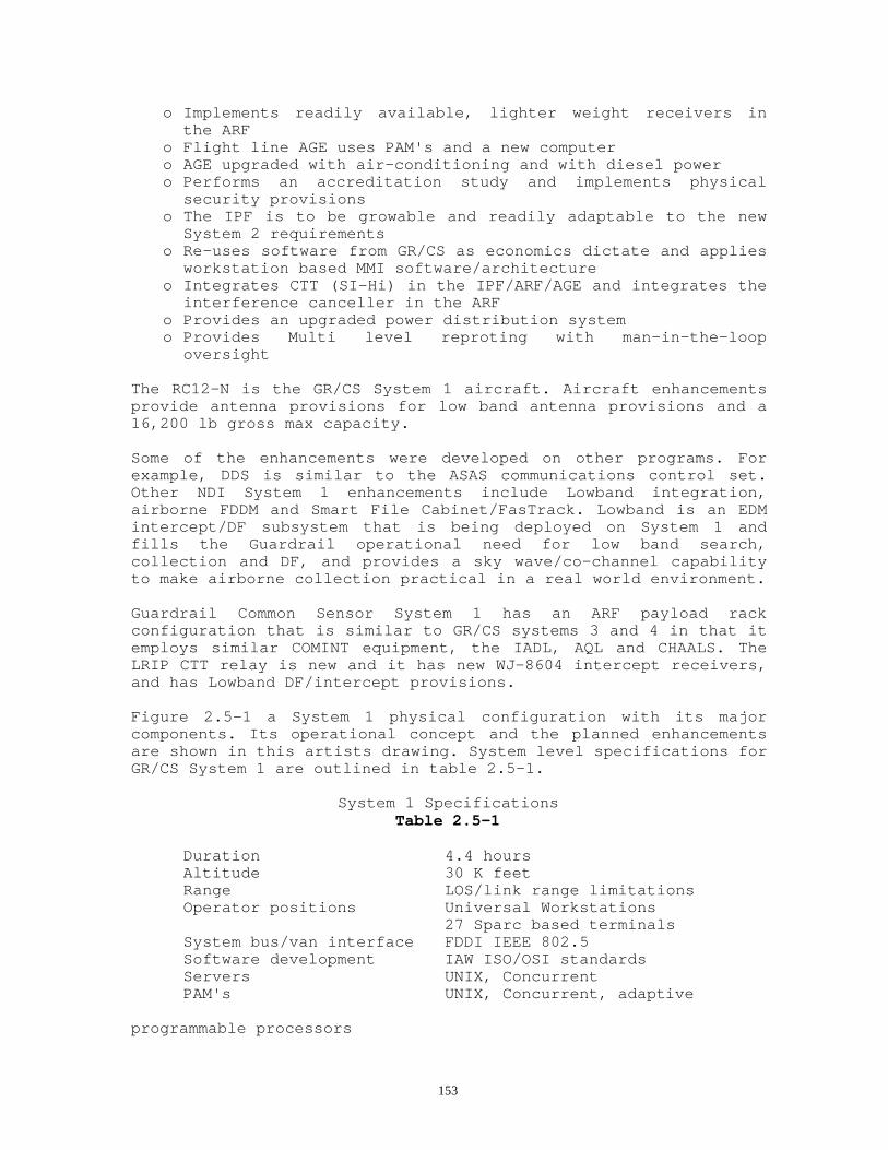
153
o Implements readily available, lighter weight receivers inthe ARF
o Flight line AGE uses PAM's and a new computero AGE upgraded with air-conditioning and with diesel powero Performs an accreditation study and implements physical
security provisionso The IPF is to be growable and readily adaptable to the new
System 2 requirementso Re-uses software from GR/CS as economics dictate and applies
workstation based MMI software/architectureo Integrates CTT (SI-Hi) in the IPF/ARF/AGE and integrates the
interference canceller in the ARFo Provides an upgraded power distribution systemo Provides Multi level reproting with man-in-the-loop
oversight
The RC12-N is the GR/CS System 1 aircraft. Aircraft enhancementsprovide antenna provisions for low band antenna provisions and a16,200 lb gross max capacity.
Some of the enhancements were developed on other programs. Forexample, DDS is similar to the ASAS communications control set.Other NDI System 1 enhancements include Lowband integration,airborne FDDM and Smart File Cabinet/FasTrack. Lowband is an EDMintercept/DF subsystem that is being deployed on System 1 andfills the Guardrail operational need for low band search,collection and DF, and provides a sky wave/co-channel capabilityto make airborne collection practical in a real world environment.
Guardrail Common Sensor System 1 has an ARF payload rackconfiguration that is similar to GR/CS systems 3 and 4 in that itemploys similar COMINT equipment, the IADL, AQL and CHAALS. TheLRIP CTT relay is new and it has new WJ-8604 intercept receivers,and has Lowband DF/intercept provisions.
Figure 2.5-1 a System 1 physical configuration with its majorcomponents. Its operational concept and the planned enhancementsare shown in this artists drawing. System level specifications forGR/CS System 1 are outlined in table 2.5-1.
System 1 SpecificationsTable 2.5-1
Duration 4.4 hoursAltitude 30 K feetRange LOS/link range limitationsOperator positions Universal Workstations
27 Sparc based terminalsSystem bus/van interface FDDI IEEE 802.5Software development IAW ISO/OSI standardsServers UNIX, ConcurrentPAM's UNIX, Concurrent, adaptive
programmable processors

154
Main System Computer Micro 5 (3 ea.)Language
Workstation/PAM AdaMSC Ada and FORTRAN
Operating systemWorkstation UNIX Sys 5MSC OS/32 rev 8.3
Graphic Motif X windows/OSFHigh accuracy location CHAALS COMINT TDOA/DD
AQL ELINT TDOANon-communications (ELINT) AQL (See Table 2.6.1-1)Audio Management System
Record channels 96Playback channels 48Capacity 162 hours
Audio Bus FDDI LAN based (Dedicated real timeLAN)
Dissemination DDS (TRI TAC, Auto DIN, MSE, STUIII)
and TRIXS IPF master station/CTTMulti level security Collateral/SCILink range LOS up to 240 KMUp-Link data rates 200 KB command (multi channel)
with anti jam capabilities,Down-Link Data rates 10.7 MB down link (multi channel)
8 ea. 1.152 MB plus 4 ea. 50 KBplus a spare 800
KB channel Link Voice channels 16 embedded in
one 1.152 MB down-link channel (Interoperable)CTT link (duplex) 50 KB (Interoperable)Primary Nav update GPSBack-up Nav update Link DME tracking and TACANMission control Intercept Command 20 KB serial,
DF/SCARS 20 KBCHAALS 20 KBAQL 20 KB
Intercept receivers VHF/UHF/P-Band (plus Lowbandextension)
Up to 14 slots (14 deployed perA/C)
Modulations AM, FM, SSB, CW, FDMBandwidths 8, 20, 50, 150, 500 K HzReceiver Control Remoted soft control Search/manual
RCUSpectrum Display Soft display of 0.5 or 1 MHzPooling Assets allocated via IPF controlMulti-channel FDDM, 120 channels (select any
12)Activity searchRecognitionUp-down flagSix down-link channels

155
DF Through-put (COMINT) Coarse: 20 per secondFine: 5 per second
DF control Automatic/single key strokeDF coverage ClassifiedDF files (COMINT) Based on frequency, operator # and
time(Contains ID, operator, modulation
& BW,lat/long and UTM, CEP and audio
log) Parameters
are stored in disk Accuracy (SIGINT)(Classified)Sensitivity (SIGINT) (Classified)Mission stand-off LOSMission aircraft RC-12NIPF ambient range -40 to +131 degrees FARF inside ambient -5 to +131 degrees FRe-deployment 4 hour tear-down
8 hour set-upTransport C-130, C-141 with K-Loader; (or)
C-5A, shipboard or improvedhighway

156
System 1 Configuration
Figure 2.5-1

157
High level system interfaces are shown in figure 2.5-2 System 1block diagram. System 1's composition is shown in Figure 2.5-3.The system is organized into three subsystems which are theAN/TSQ-176 IPF with three IGDL Trackers that are part of theAN/UPQ-3B microwave link, AN/ARF-83(V)7 ARF payloads and theAN/ARM-163(V)6 AGE which provides flight line support equipment.There are a number of used with equipment's including eight RC12-Naircraft, AN/TSC-125 CTT, the AN/MJQ-44 Power Plant,Maintenance/Storage facilities etc as shown in figure 2.5-4definition diagram.
The System 1's operational configuration differs from System 4 inthat it can operate with as few as two IPF vans at a time Vs allfour. This allows greater deployment mobility and flexible systemsizing. The internal configuration of the System 1 is vastlydifferent than other GR/CS systems. Standard "re configurable"workstations make this practical and the workstations allowsoftware to replace most of the formerly unique IPF hardware.System 1 employs a lot of NDI and ruggedized COTS equipment suchas the workstations, MSC, LAN, servers and PAM's. Where economicsdictate, System 1 re-uses GR/CS software extensively.
System 1 has multiple functions that are distributed among itsseveral major subsystems and its functional segments. Thesefunctions are treed and numbered in figure 2.5-5 as afunctional/segment breakdown.
2.5.1 System 1 Distributed Processing;
The GR/CS Surveillance Information Processing Facility AN/TSQ-176(V)(IPF) is installed in four Tempest/chemical-biological protected, C-130 transportable operator vans. Figure 2.5.1-1 Illustrates the IPFsubsystem composition and its physical configuration. The functionscontained in each van are listed in that diagram.
The Guardrail Common Sensor System 1 IPF provides the command andcontrol function for COMINT, CHALS-X, AQL and Lowband capabilitiesand does ground system data processing. It provides messagepreparation and distribution of reports as well as DDS/CTTcommunications interfaces. Figure 2.5.1-2 is an abbreviated blockdiagram of the IPF that illustrates the various interfaces to theother parts of the system. It shows the various external connectionsto land lines etc. It also illustrates the various man-machineinterfaces (MMI's). The Data Link PAM's provide buffering I/O data tothe link interfaces. Other PAM's do interfacing and provideprocessing for the communications and the DDS to the LAN.
The Guardrail Common Sensor IPF has provisions for 27 operators.Each operator has a color graphics windowed display/keyboard, withintercom/signal distribution computer control and headsets foraudio signals, digital temporary storage access and access to"soft" RCU/SDU capabilities as assigned. Audio reel to reel

158
transfer recording and time code are available at two of theoperator stations.
The ambient temperature environment of the IPF has been upgradedto handle temperatures from -40 to +131 degrees F. Other physicalimprovements include de-humidification, improved biologicalchemical operations, individual power to each van, non-interuptable power, and a built- in security system.

159
System 1 Block Diagram
Figure 2.5-2

160
System Composition
Figure 2.5-3

161

162
IPF subsystem composition
Figure 2.5.1-1

163
IPF Subsystem Interface Diagram
Figure 2.5.1-2

164
2.5.1.1 Open Architecture
The ground segment consists of four primary subsystems. Thesubsystems are functional equipment groupings which have differentfunctions in the IPF. The groupings are: The IPF Platform,Communications, IPF Information Distribution, and IPF Control andProcessing subsystems. Figure 2.5.1.1-1 provides a high levelarchitectural diagram of the IPF ground segment that illustratesthe functional association of each of these subsystem and theequipment elements contained in each subsystem.
Figure 2.5.1.1-1 Ground Segment Architectural Diagram
The IPF Platform Subsystem consists of the physical vans, racks,cabling, climate control, power distribution, lighting/securityequipment and biological/chemical protection. It also provides thevarious life support, safety and HUMINT accommodations. ThePlatform Subsystem physically supports the IPF missionelectronics.

165
The Communications Subsystem consists of all equipment utilizedfor data link transmissions to and from the airborne segments,communications self test, reporting and external net connectivity.
The Information Distribution Subsystem shown in the center of thisdiagram provides the FDDI fiber optic networks with its standardprotocol that allows information to be passed from one node to thenext within the system. This subsystem includes all servers, localarea networks, and programmable adapter modules that interface theFDDI LAN to with non-FDDI standard or mission peculiar devices.
The Control and Processing Subsystem consists of all of theelements which provide for executing the mission functionsincluding the Universal Workstations.
The IPF ground segment provides the command, control, and analysiscapability for the Guardrail system. The system operators utilizethe ground equipment to remotely control the payload on theairborne segment.
Figure 2.5.1.1-2 is a simplified block diagram of the IPF. Thisdiagram further illustrates its distributed open architecture. TheIPF units are clustered around the system's FDDI LAN's. TheUniversal Workstations are shown as one function in the diagrambut are physically and functionally distributed throughout the IPFvans and are in a standard configuration that supports all MMIrequirements.
2.5.1.2 Language/Operating System;
The IPF reuses significant System 4 MSC software as foundation andhas OS/32 revision 8.3 OS and employs Ada for new applications.The FDDI replaces the RS-232 interfaces to the operator terminalsand other IPF equipment.
2.5.1.3 Main System Computers;
Three Micro 5 computers support the re-hosted software. One actsas the MSC with location files and message data base. The secondis the ELINT system computer and the third supports CHAALS as theNavigation Processor computer. In the event of a MSC failure, theCHAALS computer can be re-configured to take over the COMINT MSCfunction. Each of the main frame computers has reserve to handleup to 256 I/O's and has two 600 M Byte disks and 105 mega bytes ofRAM.
2.5.1.4 Operators Workstations;
Workstations are SUN SPARC compatible with nineteen inch monitorwith 1280 X 1024 pixels for high resolution, color graphics with aminimum of 16 distinct colors. A graphics co-processor is used toaccelerate screen re-draw. Expandable memory will support thesystem's most memory intensive operation and leaves room forcapability growth. Example of display functions are the

166
control/display of intercept and DF data, map feature analysis,terrain and elevation map display/analysis, digital map data baseetc. Windowed displays allow for simultaneous display of operatorfunctions, messages, digital maps, audio system monitoring,spectrum display, etc.

167
IPF Simplified Block Diagram
Figure 2.5.1.1-2

168
All operator positions are equipped with "Universal SIGINTWorkstations" for standardization and for maximum flexibility.Each workstation is re-configurable to do any system function.Soft RCU's and SDU's are accessible to any position that areassigned to perform intercept/DF operation if so authorized.
2.5.1.5 Audio Storage;
Audio storage and routing is integrated into the audio managementserver, operator work stations. It has 48 playback channels and 96record channels with up to 162 hours of recording capacity.Features include auto turn-on, gap suppression, cataloging ofintercepts, sorting through previously recorded data and transferto long term storage. Signal threshold settings are available anddata can be transferred to a reel to reel analog recorder fortransfer compatibility. Audio storage and audiodistribution/intercommunications is carried on the real time FDDILAN and is controlled by individual operators and is played backat the workstations.
2.5.1.6 Data Distribution System/Reporting;
The DDS provides the external message interfaces and securityprocessing for reporting and Tactical Reconnaissance IntelligenceExchange (TRIXS). Dual CTT's are part of the DDS and are providedto handle Si High and collateral reports separately. The CTT's areinterfaced to the message data base and communications securityprocessors in the loop for data security.
Message formats are automated and can be disseminated over any ofseveral communications networks that are connected to the DDS.These include TRI-TAC/Auto Din, STU III, TIBS and GENSER. The CTT(TRIXS) interface supports TIBS, TRIXS, TRAP/TADIXS protocols.Free text or Tactical Report messages can also be received or sentvia the DDS using TRI-TAC, AUTO DIN and other operationalnetworks.
2.5.1.7 Special Signal Processor (Proforma);
The system employs the EPR-107C which is a PC workstationinstalled to process special narrow band digitized signals. Theproforma operator works and interprets intercepts the processeddata. The input is from an operator's radio or from the receiverpool. Up to two special Signal Processing (SSP)recognizers/classifiers can be tasked to identify and processformatted weapon's signal and other proforma data. Receivers areseized from the receiver pool to support the SSP tasking or it canmonitor the operators channel. Wide band SSP recognizers areplanned for on-board processing. Recognized channels will alertthe operator to engage the IPF SSP for further processing.
2.5.1.8 Smart File Cabinet/FasTrack Mission Management Tools;

169
These tools support efficient identification of battlefield nodesand has available to it the mission data base and terrain/featuresmaps to allow interactive planning and analysis. It also supportsthreat association and report generation. Its Smart File Cabinetsoftware provides powerful data base search. Fastrack mappingsoftware provides rapid overlay of collected data and has theagility required to support rapid, timely reporting of requestedtargets. It is also a valuable tool for mission planning thatincludes terrain perspective required for intelligent planning offlight tracks that assures that the platforms have a clear fieldof view coverage of planned target areas.
2.5.1.9 IPF Vans;
Normally four IPF vans are employed along with three trackers plusPower Distribution trailers and auxiliary/maintenance facilitiesat the IPF site. The vans are called Operator Vans, Computer Vanand Communications Van. Vans (#1 and #2) are operator vans withworkstations and distributed processing. Vans 1 and 2 are alikeand each provides a group of nine re-configurable operatorpositions. Van (#3) is the Communications van. It has sixworkstations and the Main System Computers. Van (#4) is theCommunications van. It has one re configurable workstation, thedata link operator position, Data Distribution System with itsoperator, and the CHAALS Processors. Its workstation is normallyused to manage the technical/test functions of the system. The IPFenclosures disconnect from their undercarriage and can be loadedinto C-130 cargo aircraft using a K-Loader. The support equipmentcan also be transported via C-130.
System 1 vans 3 and 4 can be deployed as a subset of the IPF for areduced size, easily deployable ground capability. Additional vanscan deploy as a follow-up to the re-deployment to provide moresystem capacity.
Although the System 1 IPF is quite revolutionary compared toearlier IPF's, it is downward compatible with the IGR and GR/CSplatforms.
2.5.2 System 1 ARF;
The ARF consists of mission equipment installed in an RC12-Naircraft and operates within line of sight to the IPF. The ARFmission sensors search out and collect SIGINT signals, provide DOAmeasurements and emitter location data, and does ELINT DF andELINT signal processing. The ARF has link communications, a CTTrelay and VOW communications. The system can operate beyond lineof sight with with respect to the IPF when the optionalTransportable (satellite) Relay Facility (TRF) is installed. Asshown in figure 2.5.2-1, the System 1 ARF mostly uses the samecomponents as GR/CS System 4 including CHAALS, AQL, IDL, COMINTintercept/Fast DF, SCARS, and communications with the followingexceptions:

170
System 1 ARF employs a reduced weight, broader coverage WJ 8604receiver, has the CTT LRIP relay and has a new InterferenceCanceller System (ICS). The CTT relay and ICS are the same as theretrofits planned for System 4. The new receivers have greaterfrequency coverage and broader bandwidth at a lessor cost andweight. The interference cancellers are required to protectintercept, COMINT TDOA, certain bands of DF against agile avionicsradios and the CTT relay. Racks are common to the fielded Sysem 4payload except for the EDM Lowband provisions. The ARF racklayout is shown in figure 2.5.2-2. Location of the racks withinthe platform is illustrated in figure 2.5.2-3.
Figure 2,5.2-4 is a functional diagram of the System 1 ARF. Eachof the airborne subsystems are broken out in this diagram. Notethat the rack provisions allow for the integration of the EDMLowband system payload. Three System 1 platforms have the Lowbandsearch, intercept and DF capability fully integrated. The otherplatforms have provisions for Lowband. Lowband interfaces to thelink include a 20 KB command channel and downlink data on thespare 800 KB channel. Since the EDM Lowband is an 8 channel systemit has 8 DF antennas and an intercept antenna.

171
System 1 ARF Composition
Figure 2.5.2-1

172
2.5.3 Aircraft;
The System 1 aircraft has been re-designated as the RC12-N withLowband antenna provisions and has been re-certified with a Multi-function Display (MFD)/Electronic Flight Instrument System(EFIS)/1553 bus, with upgraded avionics radios, ASE expansionprovisions and frequency extension provisions. The aircraft hashad qualification testing and re-certification with these avionicsand surface changes. The RC-12N is one of the first DOD aircraftto have the "glass cockpit" and an integrated ASE suite. The RC-12N aircraft is certified for a 16,200 pound gross weight. Figures2.5.3-1 and 2 are drawings of the aircraft and its antenna arrays.
2.5.4 System 1 AGE;
The System 1 AGE is manned, mobile vehicle that contains automatedtests and other test equipment for pre-mission start-up of the ARFelectronics. Its test capabilities interactively controls andmonitors various ARF functions. System 1's AGE employs a HP-9000-360 computer to control and monitor the ARF premission tests. TheAGE is co-located with the ARF. Figure 2.5.4-1 is an AGEabbreviated block diagram and figure 2.5.4-2 shows the AGE vanconfiguration.
2.5.5 System 1 LRIP CTT;
The CTT is a time division multiple access (TDMA) typecommunication system that connects the Guardrail IPF to thetactical commander via the ARF using TRIXS compatible protocol.The link between the IPF and ARF is a 50K Bps channel in the IDL.The relay from the ARF to the CTT field terminal is a UHF FMchannel with a single frequency mode and an agile AJ mode. The CTTrelay receives in the lower part of the UHF band and transmits isin the upper half. The purpose of the CTT is to transmit andreceive formatted reports and voice messages. The IPF becomes amaster station in the TRIXS net. There are two CTT masterterminals in the IPF. One is for SI High messages and providesboth data and voice channels. The other is for collateral messagegeneration and is only allowed to do formatted report (e.g. novoice transmissions).
The IPF mounted LRIP CTT has six units: Red/black Processor,Operator's terminal, Security Data processor (SDS), SDS terminal,SDS printer, Receiver/Transmitter Unit (RRT) and its antenna forexternal RF transmissions.
The CTT field terminal is illustrated in figure 2.5.5-1. These aresome of the same units employed at the IPF, except SDS equipmentare not included in the field terminal. The field terminal providesecure, two way tactical messages and voice communications. Itallows the tactical commanders to obtain combat tacticalintelligence generated by system 1 and provides the IPF withtasking updates and feedback from the field commander.

173
The IPF can drive up to 100 CTT field terminals on up to 5 nets.When the data flow is properly managed and reviewed for release,the IPF can transmit either collateral or SI-High CTT messages.However, voice comms are restricted over the collateral channel.

174
System 1 ARF Rack Layout
Figure 2.5.2-2

175
System 1 ARF Installation
Figure 2.5.2-3

176
ARF Functional Block Diagram
Figure 2.5.2-4

177
RC-12 N Aircraft
Figures 2.5.3-1

178
System 1 Antenna Arrays
Figures 2.5.3-2

179
AGE Van
Figure 2.5.4-1

180
AGE Block Diagram
Figure 2.5.4-2

181
2.5.6 System 1 Satellite Remote Relay;
In addition to its direct tethered mode, System 1 has a capabilityfor split base operational mode where the IPF is connected to aRemoted operational site via a DSCS satellite. (This configurationis illustrated in figure 2.5.6-1.)
The equipment for satellite remoting of System 1 is being providedby the USG and the system prime contractor as an optionalcapability. A Transportable Relay Facility (TRF) is located withinline of sight to the ARF. The TRF relays commands and data to andfrom the IPF via a satellite terminal and the DSCS III satellite.The system capability is reduced in this mode is limited to SIGINTcollection and DF with optional ELINT. This limitation relates tolimited satellite band width.
2.5.7 Support concept;
System support modes consist of deployment, mission, maintenance,and training. Deployment, maintenance, and training supportinsures system readiness. Deployment requires take down and setup, loading, transporting and some site selection/preparation.Deployments may be used for training or may involve a tacticalenvironment . The site layout is similar to System 4.
Refer to the system TM's for specific maintenance requirements.Maintenance support is defined in the Material Fielding Plan andthe System, Subsystem and LRU Technical Manuals. Trainingrequirements are defined in the T&M plan.
2.5.8 System Operational Employment/Operational Concept;
The GR/CS System 1 can be used in a variety of ways due to itsflexible design. The ground system is scale able for easytransportability in a tactical environment and is flexible inconfiguration and use.
System operations are broken into two major mode groupings;support modes and mission mode. The specific capabilities aredependent on the mode of operation, the type of tasking, theenvironment of operation, and the mission scenario.
Specific functions available to system operator personnel aredriven by the operational setup and system initialization. Setupis tailored to the mission objectives. Mission tasking iscontained within the message which is received from the Corps TCAEand is used to generate a mission definition. Tasking takes intoaccount the environment (peacetime [garrison or trainingexercise]) or tactical [deployed]), and the specific operationalscenario such as normal, interop, sat relay, etc. Tasking mayinvolve a move of the ground or airborne segment or specificmission goals to define the mission scenario. Each scenario willforce a different plan, different initialization process, andresult in a different set of functions and capabilities.

182

183
CTT Field Terminal
Figure 2.5.5-1

184
System 1 Satellite Relay
Figure 2.5.6-1

185
Specific functions available to system operator personnel aredriven by the operational setup and system initialization. Setupis tailored to the mission objectives. Mission tasking iscontained within the message which is received from the Corps TCAEand is used to generate a mission definition. Tasking takes intoaccount the environment (peacetime [garrison or trainingexercise]) or tactical [deployed]), and the specific operationalscenario such as normal, interop, sat relay, etc. Tasking mayinvolve a move of the ground or airborne segment or specificmission goals to define the mission scenario. Each scenario willforce a different plan, different initialization process, andresult in a different set of functions and capabilities.
2.5.8.1 Operator Responsibilities and System Tasking;
Mission ManagerEstablish mission goals and personnel tasking. Normally performedby a 98 C.
COMINT SupervisorThe COMINT supervisor positions are normally manned by senior 98Gs who have system experience and intercept experience. Their taskis to help individual operators and maintain the properenvironmental coverage. They verify that operators are notneedlessly overlapping and aid in passing signals to operators whomay be more experienced with certain types.
COMINT Intercept OperatorThe intercept positions are manned primarily by 98 Gs and somewhatby 98 Ds. These operators are responsible for identifyingemitters, recording and transcribing the audio or using otherequipment to perform signal analysis.
ELINT SupervisorThe ELINT supervisor is normally a senior 98 J but could also be a98 C who is trained in ELINT system operations. This persons jobis to direct the other ELINT operators and coordinate the ELINTcollection with the COMINT supervisors based on the missiontasking. The ELINT supervisor is also normally trained to generateELINT specific reports to be transmitted out of the system.
ELINT OperatorThe ELINT operator is responsible for directing the collection anddata reduction of the collected ELINT data. This position isstaffed by 98 Js. Once the data is collected, it is then passed tothe ELINT supervisor for further analysis and battlefieldevaluation.
Traffic AnalystThe traffic analyst position is manned by a 98 C who isresponsible for sorting through the situation analysis data andgenerating the various report types which end users require.
Location Analyst

186
The location analyst function is performed by an 98 C who has theresponsibility to analyze the transcripted and DF data from theCOMINT operators and the ELINT data from the ELINT operators todetermine the target area laydown and movement of units.
Tactical Communications OperatorThe TCO is a 98 C who is responsible for helping generate reportsand is also normally the final check for validity and security foroutgoing reports. This position is then responsible for selectingthe outgoing message path and transmitting the message.
Civilian Support PersonnelMost sites are supported by civilian personnel who are speciallytrained to help maintain the system and provide support to theunit operations. Examples of these contractor technicalrepresentatives (CTRs) are BASI support personnel who maintain theaircraft, Paramax personnel who support the data link and ESLpersonnel who help perform training on the mission electronics ofthe ARF, IPF, and MMV.
2.5.8.2 System Operational Scenarios
GR/CS System 1 operations are defined by the assignments tooperators and software functional allocation, resulting in aspecific set of functions available to each operator, in order tomeet various mission goals.
A description of different scenarios and their uses is provided inthe following sections for mission planning purposes.
2.5.8.2.1 Guardrail Garrison Tethered Standard Operations
This standard configuration is the standard operatingconfiguration for Guardrail/Common Sensor System 1. In thisscenario, the system relies on standard garrison support such aspower, base housing, maintenance facilities, and hangers which areproperly equipped to handle day-to-day operations and maintenance.In this configuration, the IPF and the aircraft could becollocated at the same facility but could also be split betweentwo physically separated facilities.
This scenario provides the full set of system capabilities for themission operations personnel to use. Capabilities include allmanual and automated search, collection, location, and reportingfunctions.This scenario utilizes either two or three (standard) aircraft fora mission. Figure 2.5.8.2.1-1 shows the mission configuration forthis scenario.

187
Figure 2.5.8.2.1-1 Guardrail Garrison Tethered Standard Operations Scenario
2.5.8.2.2 Guardrail Garrison Tethered Single Aircraft

188
The single aircraft configuration provides the mission plannerswith a means of performing environmental surveys without utilizingfull equipment sets. This configuration could be used prior to astandard mission as an aid to tasking or during times where eitherhardware or personnel assets were not available for a full systemmission.
This scenario provides for access to most of the systemcapabilities. The primary exception is that in the single aircraftconfiguration, neither COMINT nor ELINT TDOA is available. Figure2.5.8.2.2-1 shows the configuration for the GGTSA scenario.
Guardrail Garrison Tethered Single Aircraft ScenarioFigure 2.5.8.2.2-1
2.5.8.2.3 Quick Deployment Tactical Tethered Operations
This scenario would be used to support a quick deployment of thesystem to an alternate location in support of tactical operations.This scenario (and the next) assume that a minimal set of IPF andARF equipment is moved in support of operations. While there areseveral related configurations, the basic configuration involvestwo IPF vans, six to nine aircraft, and a minimum contingent ofsupport equipment. Figure 2.5.8.2.3-1 shows the quick deploymentmission scenario.

189
In this configuration, the IPF is working in its scaled downconfiguration, involving primarily vans 3 and 4 only (althoughdepending on fielding, vans 2 and 1 could also be added). This twovan configuration of the IPF provides for six standard operatorpositions, and a position that supports communications, test andthe data link. Both the test operator position and thecommunications operator position could be utilized as standardoperator or analyst positions if desired. In this configuration,all standard functions are available to the mission manager,however, data collection quantity would be reduced.This configuration can utilize one to three data links but thenormal configuration would be with three. To support the IPF inthis scenario, local power or the power group of the supportsegment would have to be provided.
Quick Deployment Tactical Tethered Operations ScenarioFigure 2.5.8.2.3-1

190
This scenario utilizes the GR/CS System 1 IPF as the groundcontrol segment but utilizes an Air Force payload as the airbornesegment. The specific airborne payload is the RS-6b payload inbackup mode operations. Figure 2.5.8.2.4-1 shows the interoperablescenario. Refer to table 2.5.8.1.5-1 which shows theinteroperability between the systems.
This scenario is a single aircraft scenario which provides formanual intercept and manual DF capability. This systemconfiguration is used to provide access to targets which would benormally outside of the operational area of the Guardrail aircraftor when the ARF platforms are not up.
Air Force Interop Tethered Operations ScenarioFigure 2.5.8.2.4-1

191
2.5.8.2.5 Army Tethered Interoperable Operations;
This is a set of related scenarios which utilize versions ofpayloads. The IPF can control several versions of payloads tovarying degrees as shown in table 2.5.8.2.5-1.

192
Table 2.5.8.2.5-1GR/CS System 1 Ground Segment Interoperability
CAPABILITY PAYLOAD TYPEGR/CS 1 GR/CS 4 GR/CS 3 IGRV Air Force
Comms Intercept _ _ _ _ _COMINT manualDF
_ _ _ _ _
ELINT DF _ _DS _ _ _Energy Detect _ _ _ _
_ _ _ _PAM _ _ _ _PAR _ _ _ _Auto DF _ _ _ _IEWP _ _ _ _
GS (w/o SCAR)CHAALS _ _AOI _ _ _ _CTT _ _ _Frequency Extension _FDDM _ _Ground SpecialSignals
_ _
2.5.8.3 Standard Flight Information
System performance is strongly affected by the way the sensoraircraft are flown. Aircraft altitude, track, and attitude arevery important. So are the relative spacings and headings of thesensor aircraft with respect to each other, the IPF, and theemitters of interest. To effectively execute mission goals, themission planners need to have a basic understanding of the flightfactors which influence mission operations, signal acquisition andlocation capabilities.
2.5.8.3.1 Flight Tracks;
General InformationThe flight tracks are the paths of the aircraft plotted on a map.These tracks are set up before a mission. Each aircraft flies backand forth along its individual track during the mission as thesensors collect data. As general guidelines for multi-platformmissions, the aircraft need to be flown so that:o At least two, and preferably three, sensor aircraft can"see" each target at the same time. This is an absolute necessityfor the highest accuracy available from either of the two TDOAemitter location capabilities, and is essential for good DFlocation.o The spacing between aircraft is sufficient to ensure thatthe relative signal data collected by the individual aircraft is

193
influenced by the target position. If the aircraft are too close,they will collect essentially the same data and neither the DF norTDOA systems will accurately locate the target. In general, thelocation systems will perform well when the targets are in a rangebetween 1/2 and 3 times the spread between the outside sensoraircraft.o The above conditions are sufficient for basic intercept/DFlocation/ELINT performance. A third condition must be observed toensure adequate COMINT TDOA operation. When three aircraft are up,and all three can simultaneously "see" the same target, the COMINTTDOA needs no further flight restrictions. However, if only twoaircraft are up, or if only two of three see the signal at exactlythe same time (a frequent situation), the COMINT TDOA uses adifferential Doppler (DD) mode that requires that the flighttracks be staggered or tilted (see Figure 2.5.8.3-1A,B,C).
When defining flight tracks, the following must be considered:o Geographic obstructions. Trees at close range and mountainsat any range can block the data link.o Altitude and range. Altitude and range are closely linked.The longer the distance from the trackers, the higher the altitudemust be flown. This is due to the curvature of the earth and thefact that if you fly out far enough you will eventually fly overthe horizon and out of the line of sight for the data link. Referto the system TM.o Angle of depression. The angle of the aircraft in relationto the emitter of interest must not be so steep as to defeat thesystem's ability to DF upon it. That is, targets of interest mustnot be right below the aircraft.o Distance of aircraft from each other. The aircraft must flyin relation to each other such that both aircraft can DF in thearea of interest (AOI).
The flight tracks should be designed to provide, to the maximumextent possible, the optimum direction finding geometry. Theability to accomplish this optimum geometry is affected mostnotably by the location of threat weapon systems, politicalboundaries, and in peacetime, civilian aviation restrictions. If aset of standard tracks are to be established, the overall targetarea orientation must be considered. When performing DFoperations, the required angular relationships between each of theindividual GR/CS aircraft must be maintained to ensure optimum DFaccuracy. The length of the flight tracks for the GR/CS aircraftshould be uniform so that a constant DF baseline can bemaintained. A distance of between 50 and 80 nautical miles foreach of the GR/CS aircraft tracks would not be unusual. While itis not always possible for the mission tracks to be of the samelength, it should, nevertheless, be considered a goal.
The following three figures (figures 2.5.8.3-1 A,B,C) aresuggested track configurations which can be used. The three typesof tracks shown are not the only possibilities; they are chosenonly as initial guidelines. The "3/4 Baseline U" track ispreferable to the "135 degree" track for triple ARF operation.

194
2.5.8.3.2 Flight Tracks for a Single Aircraft
The system can operate effectively with only one aircraft. Ofcourse, there will be no TDOA capability for either COMINT orELINT signals with a single aircraft. The flight track shouldsimply be the baseline from waypoint to way point in as straight aline as possible. This will provide for maximum coverage of thearea of interest. It is also possible to fly a "dog-leg" track,taking care that the center turn is under 45 degrees to avoid ablind area in the center of the track.

195
3/4 Baseline U Triad TracksFigure 2.5.8.3-1A

196
135 Degree Triad Tracks.Figure 2.5.8.3-1B

197
155 Degree Dyad TracksFigure 2.5.8.3-1C
2.5.8.33 Flight Tracks For Two Aircraft;
In some cases only two of the three aircraft are used on amission. In this case, use of the two "canted" legs as shown infigure 2.5.8.3.3-1C is best, as it will provide best coverage ofthe central area while allowing progrssive fixes with the TDOAsystem. If a longer baseline is required and only two aircraft areavailable, the two should fly the canted legs spread apart by 50to 75 km as in the three-aircraft extended profile without thecenter aircraft.
2.5.8.3.4 Calibration Tracks;
The system requires special flight tracks when calibration isrequired. Both the ELINT and COMINT arrays may require calibrationwhen major aircraft modification is performed or antenna work isperformed which affects the mounting or orientation of the arrays.
The COMINT system also may require occasional partial or completere calibration. While this is not normal, if aircraft structuralchanges occur due to repair or if major antenna damage results insignificant antenna work, calibration must at least be checked.The normal process to maintain performance of the system is toperiodically perform a verification flight and process and analyzethe data to assess current calibration integrity. The calibrationand verification process is discussed in the maintenance sectionof the system TM.
2.5.8.3.5 Altitude Selection;
Selection of the GR/CS aircraft altitude is critical to theintercept and DF results desired. The altitude flown by the GR/CSaircraft is a function of the following interrelated factors.Consideration of all of these factors is required to optimize theGR/CS collection mission:1. Location of Target Emitter(s) from Flight Tracks. This isthe most important factor. If the target emitter is close to theaircraft flight tracks, and terrain located between the aircraftand the emitter impedes the aircraft's line-of-sight (LOS) to the

198
target transmitter, the altitude of the aircraft should beincreased to reduce or eliminate this shadow effect. Increasingthe altitude of the aircraft must also take into account theeffect of LOS depression-angle error on the accuracy of directionfinding (DF) operations. Generally a depression angle of 5 degreesor less is desirable.2. Air Traffic Control (ATC). ATC can take several forms. Inpeace time the Federal Aviation Administration (FAA) or its hostcountry equivalent will impose certain restrictions on thealtitude to be flown. It is critical that the operations sectionof the GR/CS unit work closely with the ATC authorities to ensureexpedited and priority handling of their aircraft to facilitatethe maximum effectiveness of the collection mission. During timesof hostilities the altitude of the GR/CS aircraft will be assignedby the Corps Airspace Management Element (CAME), a component ofthe Corps G-3 operations section. The aircraft flown by the AerialExploitation Battalion are most likely the only aircraft organicto the Corps which will fly above the airspace coordinationaltitude. Therefore, it is imperative that the operations sectionof the GR/CS company coordinate with the CAME, to ensure theirinclusion on the Air Tasking Order (ATO). In addition, theestablishment of Restricted Operating Zones (ROZs) will berequired to ensure that protected airspace is provided for theestablishment of the desired flight tracks.3. Weather. The RC-12N aircraft used by the GR/CS System 1 hasboth temperature and altitude limitations. During certain seasonsthe aircraft will be limited in the maximum altitude it can flydue to the outside air temperature. Also the flight of theaircraft in certain icing conditions as well as turbulence ofcertain intensities will also affect DF operations. The aircraftwill be altitude limited in either case.4. Signal environment. Although the concept of "the higher thealtitude the farther the reception " may seem to be the best allaround approach, the aircraft altitude must be carefully selectedin concert with the attributes of the targeted transmitter. Forexample, if a targeted transmitter is of low power and relativelyclose to the aircraft you may not actually be able to receive it'ssignal due to the increase of higher power transmissions receivedat the higher altitude. This is a result of the increase in thedensity of the signal environment at the higher altitude.
2.5.8.3.6 Attaining Altitude;
Launching of the GR/CS aircraft must be coordinated with themission manager prior to the aircraft becoming airborne. This willassist the data link operator in establishing the required dataexchange between the aircraft and the Integrated ProcessingFacility (IPF). All aircraft should launch as close to the frontof the takeoff "window" as possible. A close takeoff sequence willhelp achieve the maximum amount of "on-station" time for all threeaircraft. All three aircraft should climb as rapidly as practicalto their mission altitude. This climb to mission altitude willassist in maximizing the collection effort by allowing theoperators in the IPF to start their intercept and DF tasks prior

199
to the aircraft reaching their flight tracks. In addition, anexpedited climb to mission altitude will allow the GR/CS aircraftto reduce their fuel consumption sooner.
2.5.8.3.7 Synchronization and Turns;
Normal coordinated turns will roll the aircraft more than 5-10degrees, and the COMINT and ELINT DF sets will turn off. (Refer tosection 2.4.8.12 for more details). Flat turns preclude this"turn-off" period, but they are difficult to perform, are time andspace consuming. It is best to fly straight and level back andforth along the tracks with short radius coordinated turns at eachend to minimize DF shut down time. A requirement is that theaircraft be "chasing" each other, not flying towards or away fromeach other.
2.5.8.3.8 Data Link Considerations;
Without the data link the aircraft can neither receive commandsnor send data back to the IPF. Periodic drop-outs due toatmospheric or geographic interference might cause a slightdegradation of performance; although this is annoying it is notcatastrophic to the system.
2.5.8.3.9 Navigation System Operations;
The system can operate in a number of navigation modes whichaffect navigation accuracy and timing accuracy of the missionequipment. The primary navigation mode is the GPS. This isfollowed in decreasing order of accuracy by data link navigationupdate mode, TACAN navigation mode, and internal navigation mode.
2.5.8.3.10 Ground Speed and Direction
A constant ground speed is desirable for DF operations of theGR/CS aircraft. Normally a cruise airspeed of between 125 - 140knots indicated is considered normal. As the mission progresses,the reduced weight caused by fuel burnoff will require a reductionof throttle power to maintain the same ground speed. Theestablishment and maintenance of constant ground speed andbaselines is essential to optimizing the GR/CS collection mission.
2.5.8.4 Scan Plan Definition

200
Scan plans define a specific frequency range and equipmentutilization for mission operations. In the case of ELINTprocessing, the scan plan defines the specific signals of interestand bands of interest which the operator sets and then uploads.The COMINT processing system uses both frequency and specificoperations types to determine the optimum use of assets
2.5.8.5 Security Accreditation
Physical and message security provide a C-2 level ofaccreditation. This limited accreditation is designed into the IPFinterfaces using log-on/logout procedures and override timer and atrusted I/O. The Security Data Processor (SDS) hardware andsoftware is used as the trusted interface with its CRC checksum, areliable review function, labeling and marking, Jounalization,miss-routing detection, null password, and audit trailcapabilities. Greater detail on these features and requirementsare described in SAR report 71-189504.

201
2.6 GR/CS Objective System Description (System 2);
Guardrail Common Sensor System 2 is nomenclatured as the AN/USD-9(V)D Special Purpose Detection System. Figure 2.6-1 illustratesthe System configuration and its major components as they areconfigured in the standard direct tether operational mode. System2 is a Corps asset that collects and accurately locates SIGINTsignals in real time and disseminates high value, target accuracy,intelligence in near real time. The system is designed to providevital information on the targeted area of interest for missionscenarios that cover: 1) peace time reconnaissance search andcollection operations (PRSCO)/training missions and 2) battlefieldtactical operations in various levels of conflicts.
Major capability enhancements to the System 2 payloads expand thesignal set capability and adds important mission flexibility tothe system with its new "Unified Architecture". The new ARFarchitecture assists in the efficient acquisition, location,signal processing and expedites situational analysis of signals ofinterest. The IPF operators can now obtain information from theARF via task oriented queries, by using predetermined signalenvironment filters or by manual operation.
GR/CS System 2 Functional DiagramFigure 2.6-1

202
System 2 is capable of operating against a large set of signals asindicated in figure 2.6-2 which indicates its multiple bandantennas and supports modern modulation types over a wide range ofCOMINT and ELINT frequency bands. Baseline System 2 mission assetsprovide the operators with the resources to acquire, identify andcopy a combination of conventional signals and exotic signals.Automated and manual analysis of collected data allows a morerapid response to tasking from tactical consumers. The pre-processed collected data is used to turn raw intercepts intousable intelligence reports which are disseminated over a varietyof communications nets. Table 2.6-1 shows the types of products,the interface, users/classification level and application.
Table 2,6-1GR/CS System Products
PRODUCT INTERFACE USER CLASSIF APPLICATION
formatted characteroriented– Klieglight– TACREP– TACELINT– Critic
landline comms& CTT airbornerelay
nationalfusion centers& aviationfire support
SCI & collateral INTEL EOB,targeting,warning
voice reports CTT airborne relay aviationspecial ops
collateral cross FLOT ops
bit orientedbroadcast (TADILtype)
Satcom (TIBS),CTT/H airbornerelay
air defense &aviationfire support
collateral targeting,warning
recorded signals withoperator comments
tapes/discs nationalfield station
SCI data exploitation,voice exploitation,training

203
Antenna Band Coverage
Figure 2.6-2

204
2.6.1 System Enhancements
The System 2 IPF is based on the System 1 IPF distributedarchitecture. Changes to the ground system are therefore limitedto those related to new system requirements that ripple into theIPF design. Major architectural changes are primarily to the ARFand AGE. All System 1 functionality is retained and the followingenhancements are added:
- CMC Architecture. The airborne Unified architecture is atechnology transfer which uses state of the are technologythat includes MCM techniques, RISC processors, and fiberoptic buses. These are all interfaced into a unified systemto provide a flexible system that has allocable processingto the various priority functions performed in payload,including conventional signals and LPI capabilities. This ashared asset approach to signal collection and distributedon-board signal processing.
- New generation CHALS-X COMINT TDOA system. CHALS-X featuresmodern VME based ground processing and expandable on-boardprocessing. It has provisions for future air to airoperation that will result in a significantly reduced CHALS-X link data rate which is needed for a daisy chained air-to-air link and a future direct satellite relay.
- Enhanced AQL ELINT uses a common CMC architecture typeairborne processor and a single panel antenna array forreduced weight. It includes antenna provisions for a drop-onreceiver that will support WB dwell-scan operation over anexpanded frequency band. Has planned future expansion thatwill provide expanded on-board processing that supportsreduced link bandwidth needed for direct satellite relay.
- New generation interoperable Multi-Role Data Link (MRDL).Includes ground based Modular Interoperable Surface Terminal(MIST), the portable GSE in the MMV , and the airborneGuardrail Dual Data Link (GDDL). The GDDL is a dual channelKu band version of the X band MIDL. The GDDL has provisionsfor air-to-air link-up between platforms concurrent withair-to-ground operation. A major improvement in the MRDL isits variable serial data rate at its I/O.
- Set-on receivers. Automatic on-board search and hand off tointercept receivers is enhanced to support several new signalacquisition scan plans.
- Wide Band Multi-element DF. A six channel DF system hasreplaced the older two channel switched baseline system. Thesystem uses six wide band tuners that are routed throughDigitizer, FFT's and signal processors using a fiber opticnetwork. The wide band front-end is required to support LPIprocessing. Automatic search rates are increased by a factorof 1000.
205
- Low Probability of Intercept (LPI). System 2 is able toacquire, track, locate and copy LPI transmissions. It cansimultaneously locate LPI and conventional emitters. Oneplatform is seized for copy when multi-search and DFfunctions are in progress.
- Identification processing. The identification processing hasbeen transferred from the IPF to the payload. This resultsin a factor of 3 increase in capacity and supports reducedlink bandwidths required for the planned future satelliterelay.
- PAM/Workstation/processing upgrades. IPF Link PAM's areupgraded to support the bulk serial MRDL interface andprovide the system communications control. An airborne datalink PAM is added to support the airborne link interface.Additional workstation software changes are incorporated tosupport the new CHALS-X and LPI.
- Upgrade the RC12-N to the RC12-P. New pods with a singlepanel ELINT array and Drop-on Receiver antenna provisionsare added. Incorporates the unified architecture racks,cables and fiber optics provisions and provides weightreductions.
- Onboard preflight checkout. The CMC architecture and the newgeneration MRDL and CHALS-X have self test and faultindicators. The on-board bus structures support end to endtest of system functions and interface to monitoring panelthat displays system health and failure modes duringpreflight check-out. This new feature allows autonomy forquick deployments and expedites premission testing.
These enhancements are defined in greater detail in the varioussections throughout section 2.6 of this document. Table 2.6.1-1provides a list of high level System 2 specifications. The maindifference between System 2 capabilities and System 1 capabilitiesresides in the sensor capabilities, its programmability and thenew signal search and scan plans.

206
Table 2.6.1-1
Duration 4.5 hoursAltitude 30 K feetRange LOS/link range limitationsOperator positions Universal Workstations
27 Sparc based terminalsSystem bus/van interface FDDI IEEE 802.5Software development IAW ISO/OSI standardsServers UNIX, Sparc basedPAM's UNIX, Sparc based adaptive
programmable processorsMSC Micro 5 (3 ea.)Language
Workstations/PAM AdaMSC Ada and FORTRAN
Operating systemWorkstation UNIX Sys 5MSC OS/32 rev 8.3
Graphic Motif X windows/OSFHigh accuracy location CHALS-X TDOA (VME based)
AQL TDOAAudio Management System
Record channels 96Playback channels 48Capacity 162 hours
Audio Bus FDDI LAN basedDissemination DDS (TRI TAC, Auto DIN,
MSE, STU III, TIBS, GENSER)Protocols TRIXS, TADIL/TRAP, TIBSCTT terminal Three ChannelMulti level security Message interface collateral/SCIData Link Multi Role Data LinkLink range 240 KMUp-Link data rates 170 KB command (multi channel)
with anti jam capabilities,(Variable rate serial rates)
Down-Link Data rates 9.216 MB down link (Serial channel)with programmable rates
Downward compatible mode 8 ea. 1.152 MB plus 4 ea. 50 KB plus a spare 800 KB channel Link Voice channels Programmable own-link channel (Interoperable)
CTT link (duplex) 50 KB (Interoperable)Primary Nav update GPSBack-up Nav update Link range/angle tracking and TAC ANMission control Intercept Command ,(programmable) DF/SCARS,
CHALS-X,AQL

207
System 2 Specifications (continued)Table 2.6.1-1
ELINT prime features Auto detect system with classifier, emitter ID & location measurement; has manual search & analysis augmentation
ELINT coverage Left/right, linear array antennasELINT search strategy Threat library, auto adapt to signal envirELINT Thru-put ClassifiedELINT DF accuracy ClassifiedPRI/PW/TOI accuracy ClassifiedELINT DF TDOA/DOAIntrapulse FMOP/PMOPOnboard data base Activity log/EPL/EOBELINT frequency range ClassifiedELINT target processing Single/multiple aircraft DOA, TDOA location
(Auto/manual, ground based)ELINT receiver group True monopulse, fast scan super-hetCOMINT Intercept receivers VHF/UHF/P-Band (expandable)
Digital NB receivers (Up to N)Set-on receivers (Up to 10)
Modulations AM, FM, SSB, CW, FDMBandwidths 8, 20, 50, 150, 500 K HzSignals Conventional, special and LPIPooling Assets allocated by data mgr softwareDF System 6 channel, wide bandMulti-channel FDDM, 120 channels (select any 12)(programmable) Activity search
RecognitionUp-down flagUp to 12 down-link channels
DF Through-put (COMINT) Coarse: X per secondFine: Y per second
DF control Automatic/single key strokeDF coverage ClassifiedDF files (COMINT) Based on ID, frequency, and time
(Contains ID, operator, modulation & BW, lat/long and UTM, CEP, audio tag) Parameters are stored in disk Accuracy (Classified)
Sensitivity (Classified)Mission stand-off LOSMission range 240 kmReceiver Control Remoted soft control SearchSpectrum Display Soft display of spectrumIPF ambient range -40 to +131 degrees FARF inside ambient -5 to +131 degrees FAircraft RC-12PRe-deployment 4 hour tear-down
8 hour set-upTransport C-130, C-141 with K-Loader; (or)
C-5A, shipboard or improved highway

208
2.6.2 System 2 Architecture Overview
The GR/CS System 2 is composed of a set of SIGINT sensors and ashared modular processing package which resides in the airbornesegment. It has a System 1 like IPF that provides the ground basedcommand, control, and processing segment which resides in a set oftransportable IPF shelters. A support segment provides variousstorage, maintenance, and support facilities.The sensor package consists of COMINT and ELINT antenna andreceiving systems with powerful back-end processing capabilities.
The system remote and local data buses are bridged together in away that is transparent to system operation. This architectureefficiently provides system functions that include manual andautomatic signal acquisition, SIGINT signal intercept monitoringand signal recording, emitter location and targeting, signalsprocessing and analysis, system control and mission planning, andintelligence reporting capabilities. The system is physicallydefined as three segments (Ground, Airborne and Support).
The Airborne Segment is the remote sensor that is linked to theGround Segment. Both the ground and airborne segments interfacewith GPS satellites to provide precision time tags and locationinformation for the collection and processing of signals. During astandard mission, system operators perform the functions of signalactivity monitoring and system control, signal acquisition,collection, location processing, signal processing, data analysis,and reporting within the Ground Segment. The system supportsmultiple reporting links such as the CTT which relays TACREPS,TACELINT reports, voice comms and has the protocol for TIBS, TRIXSand TRAP/TADIXS-B. MSE, Autodin, secure phone and secure faxcapabilities are also part of the dissemination capabilities.
2.6.2.1 Ground Segment Architecture;
The ground segment consists of four primary subsystems. Thesubsystems are functional equipment groupings which have differentfunctions but similar levels of hierarchy. The IPF Platform,Communications, IPF Information Distribution, and IPF Control andProcessing subsystems. Figure 2.6.2.1-1 provides a high leveldiagram of the ground segment architecture that illustrates thebreakdown of it functional subsystems.
The IPF Platform Subsystem consists of the physical vans, racks,cabling, climate control, power distribution, lighting/securityequipment and biological/chemical protection. It also provides thevarious life support, safety and HUMINT accommodations. ThePlatform Subsystem physically supports the IPF missionelectronics.
The Communications Subsystem consists of all equipment utilizedfor data link transmissions to and from the airborne segments,communications self test, reporting and external net connectivity.

209
The Information Distribution Subsystem shown in the center of thisdiagram provides the FDDI fiber optic networks with its standardprotocol that allows information to be passed from one node to thenext within the system. This subsystem includes all servers, localarea networks, and programmable adapter modules that interface theFDDI LAN to with non-FDDI standard or mission peculiar devices.
The Control and Processing Subsystem consists of all of theelements which provide for executing the mission functionsincluding the Universal Workstations.
Ground Segment Architectural DiagramFigure 2.6.2.1-1

210
The ground segment provides the command, control, and analysiscapability to the system. The system operators utilize the groundequipment to remotely control the payload on the airborne segment.All operator positions are equipped with "Universal SIGINTWorkstations" for standardization and for maximum systemflexibility. The operators interact with the windowed workstationterminals to perform mission tasking of the payload and are ableto view and interpret results and analyze the intelligencepreparatory to it dissemination.
2.6.2.2 Airborne Segment Advanced Tactical SIGINT Achitecture;
The GR/CS System 2 airborne segment consists of the aircraft andpayload combination. The RC12-P aircraft is the airborne platformfor System 2. There are a number of interoperable airbornesubsystems which are employed in the System 2 payload. The systemcurrently consists of nine airborne platforms. The ARF is composedof seven functionally oriented hardware subsystems which aregroups of system elements. The identified subsystems are:Collection Subsystem, SIGINT Distribution Subsystem, SIGINTProcessing Subsystem, SIGINT Receiving, Support Subsystem,Communications Subsystem, and the Platform. Figure 2.6.2.2-1provides a high level diagram of the airborne segmentarchitecture.
Figure 2.6.2.2-2 illustrates the advanced tactical SIGINT unifiedsegment architectural infrastructure used to interface distributedARF modules. There are three separate fiber optic buses on-boardthe ARF mission electronics. The FDDI LAN interfaces the controlfunctions and handles moderate bandwidth signals such as audio andlink PAM interfaces. A wide band "Data Flow" bus carries wide banddigitized signals such as digitized tuner pre-detection outputs.This net routes signals to all destinations via a fiber opticmatrix switch arrangement. It connects signals to the FFT, digitalreceiver/demodulator, signal activity detection/measurement,signal processors and other wide band processors and operates witha 0.5 G Hz clock. The third fiber optic bus provides thesynchronization for the on-board equipment. Figure 2.6.2.2-3 showsthe Common Module Carrier (CMC) chassis that holds the common LineReplaceable Modules (LRM's) that perform the Unified ARF missionsensor processing functions. Included in these functions aresignal distribution, the SIGINT processing element andcommunications element.
As in the ground segment, the airborne segment is broken down withthe "platform subsystem" identified as the physical aircraftstructure, racks, cabling, power distribution, and coolingequipment. The pilot's avionics group is considered part of the

211
platform subsystem. The antenna arrays are installed and certifiedas part of the airframe but are defined as part of the payloadelectronics.
The payload front-end is called the collection subsystem andconsists of the COMINT, ELINT and future drop-on elements. Theseare active and passive antenna arrays and related hardware.
The SIGINT Distribution Subsystem has the COMINT RF equipment thatinterfaces the antennas to the COMINT receiving elements. Thisequipment amplifies and switches RF to designated wide band andset-on receivers.
The SIGINT Receiver Subsystem has the CHALS, set-on receivers,COMINT wide band tuners and the ELINT receivers. The output ofthese elements are either digital or analog pre detection or baseband signals.

212
Airborne Segment Architectural DiagramFigure 2.6.2.2-1
SIGINT Processing works with digitized signals and generally takesplace in shared common carrier chassis. The CHALS-X digitizedsignal is processed in its processor chassis.
The ARF Support Subsystem is identified as the local area network FDDI bus and servers/onboard massstorage. It also has the touch panel that is used for an onboard end to end testing control and display.
The Communications Subsystem has all the on-board link, CTT relay, voice comms, navigation andinterference reduction equipment.

213
ATSA architecture
Figure 2.6.2.2-2

214
Common Module Carrier (CMC)
Figure 2.6.2.2-3

215
2.6.2.3 Support Segment Architecture;
The support segment includes various pieces of support equipmentwhich are part of the system and aid the mission by supplyingflight line maintenance support, storage, maintenance, and powerfunctions. The support segment is split into equipment groupingsto support ground segment and flight line operations.
2.6.3 System 2 Definition;
System 2 employs the latest technology, using military andindustrial standards to produce a modern, growable EW system whoseobject is to be fully responsive to the requirement to deal withmodern signal modulations and at the same time be sufficientlyflexible and adaptable so as to be insulated against obsolescence.The AN/USD-9(V)D is a tactical SIGINT (combined COMINT and ELINT)system designed to translate the signal environment into combatinformation. The system employs programmable remote airbornesensors to assist in the intercept, identification, classificationand location of selected signals. Processed reports are sent totactical commanders in near real time.
System composition is defined in figure 2.6.3-1. The objectivenumber of platforms is twelve. Figure 2.6.3-2 is a systemdecomposition diagram that defines how functional and physicalelements are identified. Note that system 2 has vastly enhancedcapabilities and a new architecture that is designed for growthand adaptivity. To better track this new architecture, a slightlydifferent approach to nomenclature structure has been employed todocument and define the system subsystems and functional segments.
System 2 is made up of three major subsystems and a number of"Used With" equipment's. Figure 2.6.3-3 defines the system. Thisdiagram also shows the nomenclatures and part numbers of the maincomponents. The system may also be divided into major missionfunctions such as planning, controlling, tasking, collecting,processing, analyzing, reporting and support. Since there are manyfunctional Segments in the system, figure 2.6.3-4 is extremelyinformative in understanding what these functions are, where theyreside and these sub-functions relate to the system major Segment.Figure 2.6.3-5 is a system block diagram showing the subsystemsand the system "used with" functions.

216
System 2 Composition
Figure 2.6.3-1

217

218

219

220
System 2 Simplified Block DiagramFigure 2.6.3-5
221
2.6.3.1 IPF Segment
The System 2 IPF is nomenclatured as the AN/TSQ-176(V)2Surveillance Information Processing Center. The system operatorsand IPF support segments are co-located with the IPF. Figure2.6.3.1-1 is a drawing that illustrates a typical systemoperational configuration where all equipment's are deployed. Anactual site may have less equipment, depending on the missionobjectives.
Figure 2.6.3.1-2 shows the IPF vans and outlines their functionsand operator stations in each van. The interior layout of the fourIPF vans is shown in figure 2.6.3.1-3. Note that vans 3 and 4 havethe communications and MSC's. Vans 1 and 2 are operator expansionvans.
As previously indicated, physically and electrically the System 2IPF Closely tracks System 1 IPF. Like System 1, it has NBCprotection, flexible sizing of the IPF, three trackers, UniversalWorkstations, etc. As the IPF block diagram in figure 2.6.3.1-4shows, the difference lies in the new MIST link I/O format, theCHALS-X processor, new LPI MMI and the software to support thedifferences in the new generation CHALS-X, data link and the newSystem 2 payload capabilities.
2.6.3.2 ARF Segment;
The System 2 ARF designated as the AN/ARW-83(V)8 has arevolutionary architecture that is task driven and has an expandedsensor capability. It can operate in a 1, 2 or 3 platform mode.The basic deployment is the standard direct tether mode. Thesystem is designed to be expanded to include a air-to-air daisychain mode and eventually a direct satellite relay mode. Themulti-platform modes provide instant emitter location and a broadarea coverage at stand-off ranges.
Figure 2.6.3.2-1 shows the ARF components. Figure 2.6.3.2-2 showsthe flow of this architecture and the segments that make up theequipment's that are installed in the RC12-P platform. These arebroken down into several functional Segments: COMINT collectionelement; the SIGINT Distribution subsystem; SIGINT Receivers;SIGINT Processing; ARF Support which includes the LAN, servers,bridge and touch panel; and ARF communications that includes theCTT and the Data Link. Figure 2.6.3.2-2 is a functional blockdiagram of the CMC portion of the ARF payload.
Figures 2.6.3.2-3, 4 and 5 show a simplified block diagram of theARF electronics and the integration of the modified AQL and thenew CHALS-X into the payload.

222
System Operational Configuration
Figure 2.6.3.1-1

223
IPF Composition
Figure 2.6.3.1-2

224
IPF Interior Layout
Figure 2.6.3.1-3

225
IPF Block Diagram
Figure 2.6.3.1-4

226
ARF Composition
Figure 2.6.3.2-1

227
Payload Unified DiagramFigure 2.6.3.2-2

228
System 2 ARF Block Diagram
Figure 2.6.3.2-3

229
ELINT Integration Diagram
Figures 2.6.3.2-4

230
CHALS-X Integration Diagram
Figures 2.6.3.2-5

231
2.6.3.3 MMV Segment/Support Segment;
The System 2 Support Segment has two elements: 1) Preflightcheckout, and 2) extended diagnostics/PME maintenance. System 2uses on-board self test that consists of software that is embeddedin the mission equipment. This is major change with respect to theapproach used on previous systems were an AGE van was used to dointeractive checkout and diagnostics. Extended diagnostics andtesting that goes beyond Go, No-go checkout and its remove andreplace instructions that are built into the ARF, employs a mobilemaintenance van (MMV) installed in a shelter. The MMV supports LRUrepairs and ARF maintenance problems which cannot unambiguouslydetermined with the built-in test routine. Figure 2.6.3.3-1illustrates the MMV functions. The MMV test equipment iscontrolled by the Workstation as shown in the MMV simplified blockdiagram figure 2.6.3.3-2. The System 2 AN/ARM-163(V)7 hascomputer controlled resources to stimulate test and measureresults. Like the IPF, it has an FDDI LAN that interfaces to aSun Workstation. Physically, the MMV is installed in an S-280type shelter.
2.6.3.4 Three Channel CTT Segment;
The CTT/H three channel equipment is interoperable with threedifferent network protocols. These networks include: TRIXS, TIBSand TRAP-TADIXS-B. The CTT/H-R is a receive only unit that isintended for use as a collateral consumer terminal.
These capabilities are covered in more detail in the Commander'sTactical Terminal (CTT) Program Summary and Potential Applicationsfor Tactical Intelligence Dissemination dated 1 August 1993. Thethree channel CTT is nomenclatured as the Command System TacticalCommunications Terminal AN/USC-55. The receive only 3 channel CTTis nomenclatured as the Command System, Tactical Radio ReceiverAn/USR-6 communications terminal. Figure 2.6.3.4-1 shows the CTTcomponents. Figure 2.6.3.4-2 is a drawing of the CTT fieldinstallation.
The CTT configuration in the IPF is called the TacticalReconnaissance Intelligence Exchange (TRIXS) system and haschannels assigned for collateral and SI messages. The normalrouting of transmissions is via the data link to the ARF then themessage is relayed to the CTT field terminal. The field commandercan also communicate back to the IPF.
The field terminal has six units. These include the antenna, RTT,the Red-black processor, the CRT control. The CTT is designed tohandle various message protocols that are used for direct radiotransmissions and satellite communications in tactical scenarios.

232
MMV Functions
Figure 2.6.3.3-1

233
MMV Block Diagram
Figure 2.6.3.3-2

234
CTT Three Channel EquipmentFigure 2.6.3.4-1

235
CTT Field TerminalFigure 2.6.3.4-2

236
2.6.3.5 Aircraft;
The RC12-P System 2 aircraft is an upgraded version of the RC12-Kand RC12-N GR/CS aircraft. It has a more streamlined, has alighter wing tip pod that provides an additional extendedfrequency coverage antenna, a single panel ELINT antenna array anda DF antenna array. A more weight efficient method of mounting theARF electronics has been devised. This mounting arrangement takesaway some of the weight overhead. It also accommodates thereplacement of wires with light weight serial fiber optic cables.The aircraft is designed to handle the System 2 Unified Payloadand the GDDL. Active antennas are used in the lower bands toenhance sensitivity. The towel bar antennas have been removed andevery attempt has been made to reduce drag and weight. In additionto the EFIS/ASC shared "Glass Cockpit" interface, a serial sharedcontrol has been added. Enhanced ASE provisions are alsoinstalled.
2.6.3.6 Multi Role Data Link;
The Multi Role Data Link (MRDL) is the Guardrail version of theCommon Data Link (CDL). The MRDL replaces the IDL. Thisinteroperable link is the new generation data link is used in System2 and could be retrofitted into System 1. It has three elements: theairborne Guardrail Dual Data Link (GDDL), the IPF based ModularInteroperable Surface Terminal (MIST), and the Portable GroundSupport Equipment (PGSE) that resides in the MMV.
The MIST can operate either in Ku band or X-band and has WB or NBmodes. The Guardrail version of the MIST has three trackers and isdesigned for three platform operation. It has embedded KG-68encryption. A fiber optic signal interface allows the trackers to beremoted up to 1500 ft from the IPF. This assumes that there is aremote power source to operate the tracker electronics. Five hundredfeet of fiber optic cable is supplied along with up to 100 ft ofpower cable. Physically the MIST appears like the IDL trackers usedon other Guardrails.
The GDDL is a Ku band version of the MIDL with a number ofadditional features which include:
- Ability to operate in an air-to-air mode simultaneously withthe normal ground tethered mode.
- Ability to switch between antennas to not only maintain lineof sight to the MIST, but also to track the moving air-to-air relay platform.
- Has interfaces to the GPS/INS for back-up of 1088 ft orbetter CEP.

237
- Has a programmable bulk serial I/O mode (Rates are selectableup to 170 Kb command rates and 9.216 Mb encrypted down link data rates.
In addition to the IDL like dual tracking airborne antennas, theGDDL has a dual reverse RF Amplifier for transmitting return dataand relaying commands simultaneously. It also contains a DualAirborne Modem Assembly (DAMA) that provides encoding, modulation,the receiving functions, control functions and has embeddedencryption.
When fully implemented, the GDDL will be capable of daisy chainingthe System 2 platforms. The platform nearest to the IPF can thencommunicate directly to the MIST (or) potentially can interface toa satellite terminal on-board the platform to provide DirectAirborne Satellite Relay (DASR) operation.
The GDDL is capable of self test that provides a Go, No-go test ofthe on-board data link. The GDDL interfaces to the NavigationSystem for pointing and for back-up DME position updates to thesystem.
The PGSE is packaged in two suitcase like enclosures. Wheninstalled in the MMV with its workstation, or hooked up to a Gridterminal, and has external power/GDDL connections, it performsGDDL test and diagnostics. A Spectrum analyzer is needed for themore detailed diagnostics.
Figures 2.6.3.6-1 and 2 illustrate the MRDL in the standard directtether mode and the optional air-to-air relay missionconfiguration.The Link PAM in the IPF interfaces to the MIST I/O and controlsthe command format. The GDDL likewise interfaces to the ARF BridgePAM which allocates the data content and distributes the commanddata. When implemented, it would also buffer the relay data.
2.6.4 Accreditation
Physical and message security provide a C-2 level ofaccreditation. This limited accreditation is designed into the IPFinterfaces using log-on/logout procedures and override timer and atrusted I/O. The Security Data Processor (SDS) hardware andsoftware is used as the trusted interface with its CRC checksum, areliable review function, labeling and marking, Jounalization,miss-routing detection, null password, and audit trailcapabilities. These features and requirements are similar to thosedescribed in the System 1 SAR report.
2.6.5 Embedded Training
Embedded training pertains to operator proficiency training andsimulated maintenance training tools. The workstation architectureemployed in the modern IPF is ideally suited to this application.Although there is New Equipment Training (NET) courses designed

238
for the new system, it has been shown that on-the-job training isthe primary source of operator and maintenance proficiencyoptimization in a tactical system.
The system currently provides a simulator that generates TDOA andDOA DF data in response to General and Directed search and manualDF requests. It allows emitters to be defined by the operator,lets the operator practice location analysis and allowsassociation of DF data with simulated audio. This is very usefulin refreshing operators skills in DF collection, locationanalysis, situation analysis and report commands.
Future upgrades will add mission relevant scenarios so that themission managers can set up complex mission objectives withsimulated realist tactical situations including emitter nets. Theoperator staff then can participate actively in carrying outsimulated missions that more realistically reflect the real worldtarget environment. These future upgrades to "embedded training"will provide low cost mission operator training with the realismthat will prepare the operator for the pressures and rigorsencountered in battlefield operations and in live field trainingexercises.

239
MRDL in Standard Tethered ModeFigures 2.6.3.6-1

240
MRDL in Optional Air-to-Air Relay ModeFigure 2.6.3.6-2

241
The existing built-in system diagnostics are applicable tomaintenance training, however with some additional software,simulated failures and practice corrective actions can be readilyadded to allow support personnel to maintain their repair skillsat a readiness level.
2.6.6 Sensor Management PIPs;
The objective of the sensor management enhancements has been toincrease intelligence through-put in response to specific taskingwith improved timeliness of critical reports. It has also become akey mission planning tool. Initial threat association improvementsare focused on obtaining real time alerts as the battlefieldsituation develops and ultimately greater automation that willallow more efficient correlation and validation of multi-sensordata. The workstation windowed display is the sensor managementoperator interface.
The Smart File Cabinet/Sybase Data Manger which provides access tothe system data base and the FasTrack smart map capability whichprovides situational graphics and threat association, are keyelements that were used for upgrading sensor management tools.Many of these tools are currently being evaluated on Systems 3 & 4in the field and new features are continually being added.
Initial capabilities provide access to an extensive digital mapdata base that supports target area feature analysis and hasterrain elevation data that is used during mission planning andduring the mission to assure a field of view of the area ofinterest. The mission managers also use the map data base tointeractively overlay collected data onto natural terrain featuresand man made features such as roads, bridges, junctions,installations, towns etc.
Battlefield nodes are tied together by association of voice nets,LPI nets, multi channel nets and special signal activity.Exploitation of digital signals supports the operators withadditional intelligence normally associated with nodes ofbattlefield operations and command posts. Initially, access to themission sensor data base and some event triggers provide activityalerts. These support migration of data necessary for specificnode analysis. Using terrain and battlefield maps, the missionmanager is involved in the planning of flight tracks, altitude forclear field of view, establishes search lists both during planningand as the mission develops so as to insure that there is a goodfit with initialization/pre-correlation displays for sensormanagement implementation that will best support the missionobjectives and tasking requirements.
Further automation is being looked at as method of speeding up theprocess. A key consideration in development of these tools, is notonly current utility, but that the architecture being implementedfits in with continued growth to insure that tools can be easily

242
added to assure that intelligence gaps can be quickly identifiedso that mission resources can be best focused on the missionobjective. This includes efficiently controlling task drivenresources on-board the platform and ability to monitor andcorrelate results of computer controlled search and automaticemitter location. The result is that time lag between events andreporting will continue to shortened. Continued improvement in theuse of the SIGINT data base and growth to more efficiently useother available data to correlate EOB and validate target datathat potentially can go directly to Quick Fire over the collateralCTT net is a potential, foreseeable threat correlation/sensormanagement capability.
Current tools being used for sensor management include the terrainmaps, geo-sort, upgraded search functions with tailored scanplans, and more sophisticated text transfer that allows themission manager to be more efficient in making use of the system'svast collection capabilities as the mission operator responds tocritical intelligence requirements in a complex battlefieldenvironment.
The objective continues be, to use the enhanced "task drivenSIGINT system" to support the operator in obtaining requested datain real time so that the mission manager can accurately assesscollected data on his windowed workstation using his "sensormanagement tools" and report it in time to use it as a targetinginput for battle plan execution (including collateral TAC ELINTreports and collateral reports on SIGINT nodes), using theexpanded Guardrail dissemination network interfaces and the threechannel CTT.
2.6.7 Support concept;
System support modes consist of deployment, mission, maintenance,and training. Deployment, maintenance, and training supportinsures system readiness. It involves getting the system to itsoperational site, making sure it works, and making sure themaintenance personnel know how to test and repair it and that theoperator personnel know how to use it properly. Deploymentrequires take down and set up, loading, transporting and some siteselection/preparation. Deployments may be used for training or mayinvolve a tactical environment.
The system has a three level maintenance support concept: First,Organizational which involves identification of faults and removaland replacement of LRU's and minor repairs where boxes or linereplaceable modules are not spared, or where the fault is withwiring or a hard mounted component. Second, Direct which handlesany on-site box repair and routine maintenance including aircraftmaintenance. And third, Depot Support which includes factoryrepairs, government depots and certain COTS equipment's that arenon-field repairable. There is a plan to combine the first twolevels.

243
Refer to the system TM's for specifics. Maintenance support isdefined in the Fielding Plan and the System, Subsystem and LRUTechnical Manuals. Training requirements are defined in the T&Mplan.
System 2 airborne segment contains embedded pre-flight go, no-gotest functions which performs complete end to end readinesstesting. System 2 also generally supports fault isolation to theLRM/CCA/module for the COMINT equipment, CHALS-X, the ELINTprocessor and the data link to the chassis level.
The support concept is illustrated in figures 2.6.7-1 and 2.6.7-2.

244
Support Segment Functional DiagramFigure 2.6.7-1
Support Segment Configuration DiagramFigure 2.6.7-2
2.6 8 System Employment/Operational Concept

245
The GR/CS System 2 can be used in a variety of ways due to itsflexible design. The payload can be configured to optimizecollection on specific signal types, can perform acquisition andlocation functions without ground control, is self-testing forpre-mission readiness, and is fail-soft for reliable operation.The ground system is scale able for easy transportability in atactical environment and is flexible in configuration and use.
System operations are broken into two major mode groupings;support modes and mission mode. The specific capabilities used ortasks performed by mission personnel at any specific time aredependent on the mode of operation, the type of tasking, theenvironment of operation, and the mission scenario.
To understand system operations, the primary functions areorganized in a hierarchical two dimensional structure. The levelsof the hierarchy are:
Level 1 - Fielded System Operations (phase). This is thephase the system is in once it is delivered to the users formission operations. This is the phase the remainder of thehierarchy supports. Other phases of a system include conceptdefinition, design & development, test, and decommission.
Level 2 - System Modes (mutually exclusive for an element).Modes define conditions of planning and operation of thesystem which are mutually exclusive for particular systemelements. Different system elements can be in differentmodes at different times. There are two mode groupings asstated previously; support and mission. Support modes arethose which contribute to the system performing the missionand require planning and training but are not directlyinvolved in mission operations. The support modes aretransport, maintenance, and mission training. The fourthsystem mode is mission. Mission mode contains all of theoperational functionality of the system.
Level 3 - System States (mutually exclusive for an element).States are time phased operations for the system. There arefour defined states for each system mode.
Level 4 - State Functions (concurrent operations). Functionsare the activities which occur at the heart of any state.Each state consists of multiple functions which can beperformed. However, the specific functions available tooperations personnel at any point are dependent on themission tasking, goals, and scenario. In mission mode during
246
the operation state, functions include acquisition,collection, data processing, etc.
Level 5 - Functional Capabilities. Capabilities aresubgroups of functions and provide the next level ofspecification. For example, under the acquisition function,capabilities are defined as manual, automatic, and visual.
Level 6 - Capability Threads. Threads are the lowest levelof functional definition at the system level and definespecific types of mission operations. A thread is defined asall actions from a trigger to a product. As an example, amanual DF thread would be described as 1) operator pushes DFbutton 2) command generated in workstation 3) message passedover LAN to DFP 4) DFP queues message and passes to aircraft5) message is passed into airborne manual queue and thenparsed into a sequence of events for the RFD and tuner 6)incoming RF is digitized, narrow banded, measured on 6simultaneous channels 7) LOB calculations are performed 8)response message sent to data link and back to IPF 9) DFPgets response and returns to operator workstation 10) LOB isdisplayed on operator display. Threads will be describedfrom the operators perspective as part of this document butonly to a level required for understanding of the systemoperations.
Level 7 - Thread Definitions. This level of operationalhierarchy is quite involved hence will not be included inany detail this document but the definitions are includedhere for informational purposes. This level is used todefine the breakdown of threads into component sub threadsfor each portion of the operation. This level of definitioncan be as high as IPF to ARF or as low as a processhappening totally within a single processing element.
As has been stated, the specific functions available to systempersonnel at any point in time is driven by another group ofcharacteristics which define the operational setup for a specificmission. The mission definition is defined by a tasking hierarchywhich defines a third dimension to the system functionaldefinitions. Tasking is contained within the message which isreceived from the Corps TCAE and used to generate a missiondefinition. Tasking takes into account the environment (peacetime[garrison or training exercise]) or tactical [deployed]), and thespecific operational scenario such as normal, interop, sat relay,etc. Tasking may involve a move of the ground or airborne segment

247
or specific mission goals to define the mission scenario. Eachscenario will force a different plan, different initializationprocess, and result in a different set of functions, capabilities,and threads. The tasking hierarchy for GR/CS System 2 is:
Level 1 - Tasking
Level 2 - Environment
Level 3 - Scenario
2.6.8.1 Operator Responsibilities and System Tasking
Mission Manager
Establish mission goals and personnel tasking. Normally performedby a 98 C.
COMINT Supervisor
The COMINT supervisor positions are normally manned by senior 98Gs who have system experience and intercept experience. Their taskis to help individual operators and maintain the properenvironmental coverage. They verify that operators are notneedlessly overlapping and aid in passing signals to operators whomay be more experienced with certain types.
COMINT Intercept Operator
The intercept positions are manned primarily by 98 Gs and somewhatby 98 Ds. These operators are responsible for identifyingemitters, recording and transcribing the audio or using otherequipment to perform signal analysis.
ELINT Supervisor
The ELINT supervisor is normally a senior 98 J but could also be a98 C who is trained in ELINT system operations. This persons jobis to direct the other ELINT operators and coordinate the ELINTcollection with the COMINT supervisors based on the missiontasking. The ELINT supervisor is also normally trained to generateELINT specific reports to be transmitted out of the system.
ELINT Operator
The ELINT operator is responsible for directing the collection anddata reduction of the collected ELINT data. This position isstaffed by 98 Js. Once the data is collected, it is then passed tothe ELINT supervisor for further analysis and battlefieldevaluation.
Traffic Analyst

248
The traffic analyst position is manned by a 98 C who isresponsible for sorting through the situation analysis data andgenerating the various report types which end users require.
Location Analyst
The location analyst function is performed by an 98 C who has theresponsibility to analyze the transcripted and DF data from theCOMINT operators and the ELINT data from the ELINT operators todetermine the target area laydown and movement of units.
Tactical Communications Operator
The TCO is a 98 C who is responsible for helping generate reportsand is also normally the final check for validity and security foroutgoing reports. This position is then responsible for selectingthe outgoing message path and transmitting the message.
Civilian Support Personnel
Most sites are supported by civilian personnel who are speciallytrained to help maintain the system and to support the unitoperations. Examples of these contractor technical representatives(CTRs) are BASI support personnel who maintain the aircraft,Paramax personnel who support the data link and ESL personnel whohelp perform training on the mission electronics of the ARF, IPF,and MMV.

249
2.6.8.2 System Operational Scenarios
GR/CS System 2 operations are defined by seven operationalscenarios. Each scenario utilizes a unique configuration of systemresources and assets, resulting in a specific set of functionsavailable to the operator, in order to meet various mission goals.
A description of each scenario and its uses is provided in thefollowing sections. The eight definitions are provided as theprimary guidelines for system utilization. This is not to implythat other combinations of system assets are not possible.However, these system deployment definitions outline here providea broad spectrum of capability for mission planning purposes andare illustrated in diagrams in the following sections.
2.6.8.2.1 Guardrail Garrison Tethered Standard Operations
The standard, tethered configuration is the normal three aircraftoperating configuration for Guardrail/Common Sensor System 2. Inthis scenario, the system relies on standard garrison support suchas power, base housing, maintenance facilities, and hangers whichare properly equipped to handle day-to-day operations andmaintenance. In this configuration, the IPF and the aircraft couldbe collocated at the same facility but could also be split betweentwo physically separated facilities.
This scenario provides the full set of system capabilities for themission operations personnel to use. This includes all manual andautomated search, collection, location, and reporting functions.
This scenario utilizes either two or three (standard) aircraft fora mission. Figure 2.6.8.2.1-1 shows the mission configuration forthis scenario.
2.6.8.2.2 Guardrail Garrison Tethered Single Aircraft (GGTSA)
The single aircraft configuration provides the mission plannerswith a means of performing environmental surveys without utilizingfull equipment sets. This configuration could be used prior to astandard mission as an aid to tasking or during times where eitherhardware or personnel assets were not available for a full systemmission.
This scenario provides for access to most of the systemcapabilities. The primary exception is that in the single aircraftconfiguration, neither COMINT nor ELINT TDOA is available. Figure2.6.8.2.2-1 shows the configuration for the GGTSA scenario.

250

251
Guardrail Garrison Tethered Standard
Operations Scenario
2.6.8.2.1-1
Guardrail Tethered Single Aircraft ScenarioFigure 2.6.8.2.2-1
This scenario would be used to support a quick deployment of thesystem to an alternate location in support of tactical operations.This scenario (and the next) assume that a minimal set of IPF andARF equipment is moved in support of operations. While there areseveral related configurations, the basic configuration involvestwo IPF vans, six aircraft, and a minimum contingent of supportequipment. Figure 2.6.8.2.3 shows the quick deployment missionscenario.
In this configuration, the IPF is working in its scaled downconfiguration, involving primarily vans 3 and 4 only (althoughdepending on fielding, vans 2 and 1 could also be added). This twovan configuration of the IPF provides for six standard operatorpositions, a communications operator, a test operator and a linkoperator. Both the test operator position and the communicationsoperator position could be utilized as standard operator oranalyst positions if desired. In this configuration, all standard
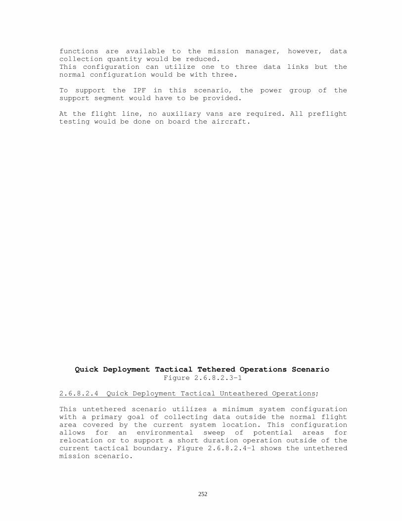
252
functions are available to the mission manager, however, datacollection quantity would be reduced.This configuration can utilize one to three data links but thenormal configuration would be with three.
To support the IPF in this scenario, the power group of thesupport segment would have to be provided.
At the flight line, no auxiliary vans are required. All preflighttesting would be done on board the aircraft.
Quick Deployment Tactical Tethered Operations ScenarioFigure 2.6.8.2.3-1
2.6.8.2.4 Quick Deployment Tactical Unteathered Operations;
This untethered scenario utilizes a minimum system configurationwith a primary goal of collecting data outside the normal flightarea covered by the current system location. This configurationallows for an environmental sweep of potential areas forrelocation or to support a short duration operation outside of thecurrent tactical boundary. Figure 2.6.8.2.4-1 shows the untetheredmission scenario.

253
The untethered mode will utilize a single aircraft. Preflight onthe aircraft proceeds as normal. After preflight is complete, theaircraft is launched and establishes communications with the IPF.
The test operator performs the standard series of quick BIT checkson the payload in order to assure proper operations. The missionmanager then uploads an automatic scan plan data filter windows tothe payload processor.
The aircraft then flies out of data link range to the target areaand sets up in a standard collection racetrack. The pilots wouldfly this track for a TBD duration, collecting requested data whichis automatically stored on board.
The aircraft would then fly back into the standard link range ofthe IPF to a predefined re acquisition point. Once the data linkhas been reestablished, the mission manager or mission analystcould then perform various queries on the airborne data base toretrieve data on emitters and nets. No audio data is available.
Quick Deployment Tactical Untethered Operations ScenarioFigure 2.6.8.2.4-1
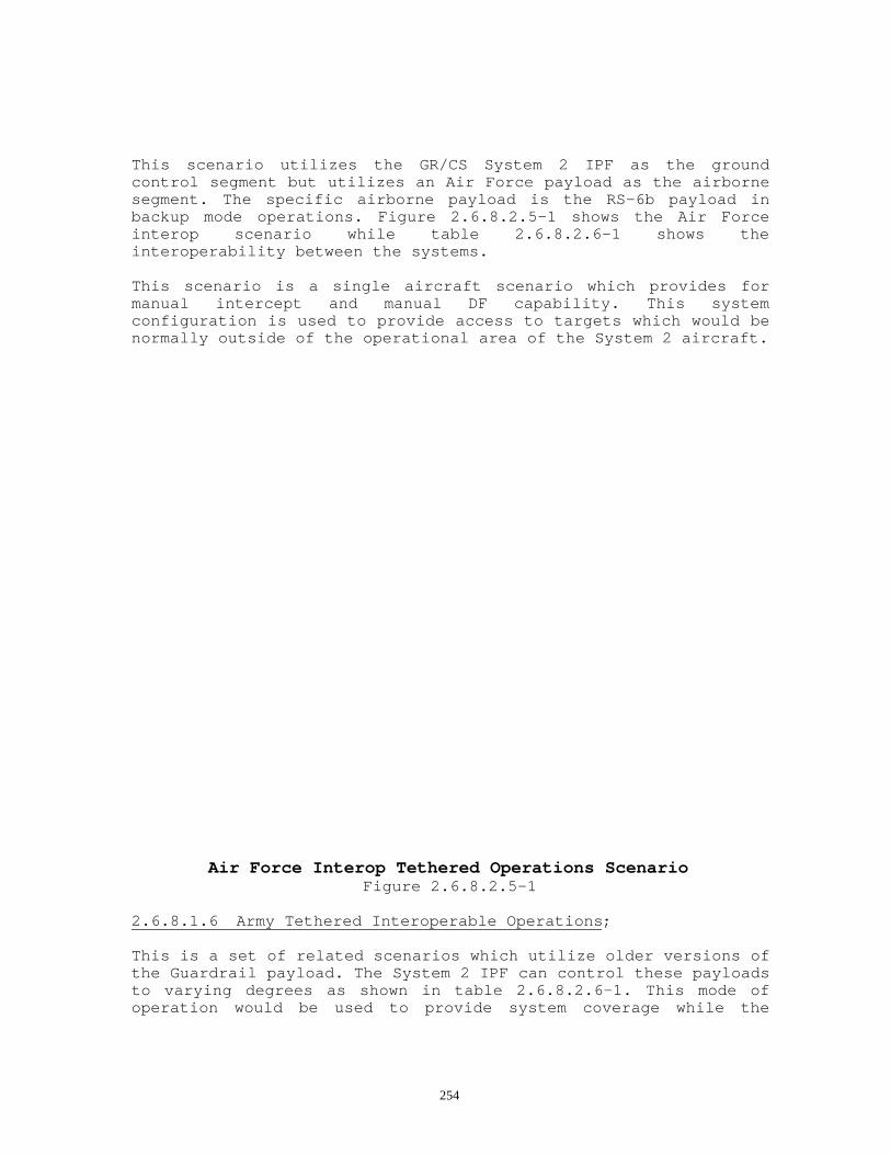
254
This scenario utilizes the GR/CS System 2 IPF as the groundcontrol segment but utilizes an Air Force payload as the airbornesegment. The specific airborne payload is the RS-6b payload inbackup mode operations. Figure 2.6.8.2.5-1 shows the Air Forceinterop scenario while table 2.6.8.2.6-1 shows theinteroperability between the systems.
This scenario is a single aircraft scenario which provides formanual intercept and manual DF capability. This systemconfiguration is used to provide access to targets which would benormally outside of the operational area of the System 2 aircraft.
Air Force Interop Tethered Operations ScenarioFigure 2.6.8.2.5-1
2.6.8.1.6 Army Tethered Interoperable Operations;
This is a set of related scenarios which utilize older versions ofthe Guardrail payload. The System 2 IPF can control these payloadsto varying degrees as shown in table 2.6.8.2.6-1. This mode ofoperation would be used to provide system coverage while the

255
primary system 2 aircraft were being moved to an alternatelocation.
2.6.8.2.7 Extended Teathered Range Air-to-Air (Future);
This scenario allows for operations outside of the normaloperational area of GR/CS System 2 with full capability. In thismode, three aircraft are utilized, one as a tetheredrelay/collector, one as an air-to-air relay/collector, and one asa prime collector. Figure 2.6.8.2.7-1 shows the EXTRAA scenario.
In this scenario, preflight operations are performed as normal.Once the aircraft are launched, they proceed to the flight area.Once there, the tethered relay collector aircraft establishes alink with the IPF. With the aid of the pilots, this aircraft thenestablishes the air-to-air link with the second aircraft. Oncethis link is established, the second and third aircraft link up ina similar manner.
At this point, all normal system functionality is available. Thisscenario functions like the standard multi-aircraft tetheredscenarios with the exception that a large majority of theprocessing is now done on board rather than in the IPF to reducedata link traffic. There are also some operational considerationsas to the number of available audio channels.
Table 2.6.8.2.6-1GR/CS System 2 Ground Segment Interoperability
CAPABILITY PAYLOAD TYPEGR/CS 1 GR/CS 4 GR/CS 3 IGRV Air Force
Comms Intercept _ _ _ _ _COMINT manualDF
_ _ _ _ _
ELINT DF _ _Directed SearchEnergy Detect _ _ _ _Geoscreen _ _ _ _
PAM _ _ _ _PAR _ _ _ _Auto DF _ _ _ _IEWP _ _ _ _
GS (w/o SCAR)CHAALS _ _AOI _ _ _ _CTT _ _ _Frequency Extension _FDDM _ _

256
Ground SpecialSignals
_

257
Extended Range Tethered Air-to-Air Relay ScenarioFigure 2.6.8.2.7-1
2.6.8.2.8 Direct Air-to-Satellite Relay (DASR) (future)
This scenario is functionally the same for the aircraft as theExtended Range scenario, however, the IPF relay would be throughthe last relay aircraft direct to a satellite rather than througha tethered data link to the ground. Figure 2.6.8.2.8-1 shows theDASR scenario.

258
Direct Air-to-Satellite Relay ScenarioFigure 2.6.8.2.8-1

259
2.6.8.3 Standard Flight Tracks;
System performance is strongly affected by the way the sensoraircraft are flown. Aircraft altitude, track, and attitude arevery important. So are the relative spacings and headings of thesensor aircraft with respect to each other, the IPF, and theemitters of interest. To effectively execute mission goals, themission planners need to have a basic understanding of the flightfactors which influence mission operations, signal acquisition andlocation capabilities.
2.6.8.3.1 Flight Tracks;
General InformationThe flight tracks are the paths of the aircraft plotted on a map.These tracks are set up before a mission. Each aircraft flies backand forth along its individual track during the mission as thesensors collect data. As general guidelines for multi-platformmissions, the aircraft need to be flown so that:o At least two, and preferably three, sensor aircraft can"see" each target at the same time. This is an absolute necessityfor the highest accuracy available from either of the two TDOAemitter location capabilities, and is essential for good DFlocation.o The spacing between aircraft is sufficient to ensure thatthe relative signal data collected by the individual aircraft isinfluenced by the target position. If the aircraft are too close,they will collect essentially the same data and neither the DF norTDOA systems will accurately locate the target. In general, thelocation systems will perform well when the targets are in a rangebetween 1/2 and 3 times the spread between the outside sensoraircraft.o The above conditions are sufficient for basic intercept/DFlocation/ELINT performance. A third condition must be observed toensure adequate COMINT TDOA operation. When three aircraft are up,and all three can simultaneously "see" the same target, the COMINTTDOA needs no further flight restrictions. However, if only twoaircraft are up, or if only two of three see the signal at exactlythe same time (a frequent situation), the COMINT TDOA uses adifferential Doppler (DD) mode that requires that the flighttracks be staggered or tilted (see Figure 2.6.8.3-1).When defining flight tracks, the following must be considered:o Geographic obstructions. Trees at close range and mountainsat any range can block the data link.o Altitude and range. Altitude and range are closely linked.The longer the distance from the trackers, the higher the altitudemust be flown. This is due to the curvature of the earth and thefact that if you fly out far enough you will eventually fly overthe horizon and out of the line of sight for the data link. Referto TM 11-5865-273-12, Figure 2-2, Track Range vs. AircraftAltitude.o Angle of depression. The angle of the aircraft in relationto the emitter of interest must not be so steep as to defeat the

260
system's ability to DF upon it. That is, targets of interest mustnot be right below the aircraft.o Distance of aircraft from each other. The aircraft must flyin relation to each other such that both aircraft can DF in thearea of interest (AOI).The flight tracks should be designed to provide, to the maximumextent possible, the optimum direction finding geometry. Theability to accomplish this optimum geometry is affected mostnotably by the location of threat weapon systems, politicalboundaries, and in peacetime, civilian aviation. If a set ofstandard tracks are to be established, the overall target areaorientation must be considered. When performing DF operations, therequired angular relationships between each of the individualGR/CS aircraft must be maintained to ensure optimum DF accuracy.The length of the flight tracks for the GR/CS aircraft should beuniform so that a constant DF baseline can be maintained. A lengthof between 50 and 80 nautical miles for each of the GR/CS aircrafttracks would not be unusual. While it is not always possible forthe mission tracks to be of the same length, it should,nevertheless, be considered a goal.
The following three figures (figures 2.6.8.3-1A,B,C) are suggestedtrack configurations which can be used. The three types of tracksshown are not the only possibilities; they are chosen only asinitial guidelines. The "3/4 Baseline U" track is preferable tothe "135 degree" track for triple ARF operation.

261
3/4 Baseline U Triad TracksFigure 2.6.8.3-1A

262
135 Degree Triad Tracks.Figure 2.6.8.3-1B

263
155 Degree Dyad TracksFigure 2.6.8.3-1C
The system can operate effectively with only one aircraft. Therewill be no TDOA capability for either comms or non-comms signalswith a single aircraft. The flight track should simply be thebaseline from waypoint to way point in as straight a line aspossible. This will provide for maximum coverage of the area ofinterest. It is also possible to fly a "dog-leg" track , takingcare that the center turn is under 45 degrees to avoid a blindarea in the center of the track. The dog-leg track will allow forslightly enhanced coverage of the center mission area, but thestraight line leg for longer baseline is preferred. With a singleaircraft there is also more flexibility in the track distance andflight operation since there are no turns to coordinate and thetrack can extend as far along the signal of interest front asdesired. Single aircraft track considerations should be kept inmind for the untethered operations scenario of the system.2.6.8.3.3 Flight Tracks for Two Aircraft;
In some cases only two of the three aircraft are used on amission. In this case, use of the two "canted" legs as shown infigure 2.6.8.3.3-1C is best, as it will provide best coverage ofthe central area while allowing running fixes with the TDOAsystem. If a longer baseline is required and only two aircraft areavailable, the two should fly the canted legs spread apart by 50to 75 km as in the three-aircraft extended profile without thecenter aircraft.
2.6.8.3.4 Calibration Tracks;
The system requires special flight tracks when calibration isrequired. Both the ELINT and COMINT arrays will requirecalibration when major aircraft modification is performed orantenna work is performed which affects the mounting ororientation of the arrays.
The ELINT system requires calibration, known as "panel bias", anytime that certain maintenance or installation of an antenna panelis performed. A minimum of two consecutive turns in each directionon the circular path will comprise a complete panel bias flight.
The COMINT system also may require occasional partial or completere calibration. If aircraft structural changes occur due to repairor if major antenna damage results in significant antenna work,calibration must at least be checked. The COMINT arrays requirethat the calibration be done at two depression angles, forcing theselection of flight tracks. The primary depression angle forcalibration is two degrees and the secondary angle is sevendegrees.

264
The normal process to maintain performance of the system is toperiodically perform a calibration verification flight and processand analyze the data to validated calibration integrity. Thecalibration and verification process is discussed in themaintenance section of the system TM. In setting up calibrationareas, at least three areas must be located; one for the ELINTpanel bias against a known emitter set, one for primarycalibration for the COMINT arrays, and one for the secondarydepression angle for the COMINT arrays.
2.6.8.3.5 Altitude Selection;
Selection of the GR/CS aircraft altitude is critical to theintercept and DF results desired. The altitude flown by the GR/CSaircraft is a function of the following interrelated factors.Consideration of all of these factors is required to optimize theGR/CS collection mission:
1. Location of Target Emitter(s) from Flight Tracks. This isthe most important factor. If the target emitter is close to theaircraft flight tracks, and terrain located between the aircraftand the emitter impedes the aircraft's line-of-sight (LOS) to thetarget transmitter, the altitude of the aircraft should beincreased to reduce or eliminate this shadow effect. Increasingthe altitude of the aircraft must also take into account theeffect of LOS depression-angle error on the accuracy of directionfinding (DF) operations. Generally a depression angle of 5 degreesor less is desirable.
2. Air Traffic Control (ATC). ATC can take several forms. Inpeace time the Federal Aviation Administration (FAA) or its hostcountry equivalent will impose certain restrictions on thealtitude to be flown. It is critical that the operations sectionof the GR/CS unit work closely with the ATC authorities to ensureexpedited and priority handling of their aircraft to facilitatethe maximum effectiveness of the collection mission. During timesof hostilities the altitude of the GR/CS aircraft will be assignedby the Corps Airspace Management Element (CAME), a component ofthe Corps G-3 operations section. The aircraft flown by the AerialExploitation Battalion are most likely the only aircraft organicto the Corps which will fly above the airspace coordinationaltitude. Therefore, it is imperative that the operations sectionof the GR/CS company coordinate with the CAME, to ensure theirinclusion on the Air Tasking Order (ATO). In addition, theestablishment of Restricted Operating Zones (ROZs) will berequired to ensure that protected airspace is provided for theestablishment of the desired flight tracks.
3. Weather. The RC-12P aircraft used by the GR/CS system hasweather, temperature and altitude limitations. During certainseasons the aircraft will be limited in the maximum altitude itcan fly due to the outside air temperature. Also the flight of theaircraft in certain icing conditions as well as turbulence ofcertain intensities will also affect the performance of DF

265
operations. In any case the aircraft will be limited to itsceiling altitude.
4. Signal environment. Although the concept of "the higher thealtitude the farther the reception " may seem to be the best allaround approach, the aircraft altitude must be carefully selectedin concert with the attributes of the targeted transmitter. Forexample, if a targeted transmitter is of low power and relativelyclose to the aircraft you may not actually be able to receive it'ssignal due to the increase of higher power transmissions receivedat the higher altitude. This is a result of the increase in thedensity of the signal environment at the higher altitude.
2.6.8.3.6 Attaining Altitude;
Launching of the GR/CS aircraft must be coordinated with themission manager prior to the aircraft becoming airborne. This willassist the data link operator in establishing the required dataexchange between the aircraft and the Integrated ProcessingFacility (IPF). The aircraft should launch as close to the frontof the takeoff "window" as possible. The second and third aircraftshould try to take off as soon after the preceding as possible.This close takeoff sequence will help achieve the maximum amountof "on-station" time for all three aircraft. Additionally, allthree aircraft should climb as rapidly as practical to theirmission altitude. This climb to mission altitude will assist inmaximizing the collection effort by allowing the operators in theIPF to start their intercept and DF tasks prior to the aircraftreaching their flight tracks. In addition, an expedited climb tomission altitude will allow the GR/CS aircraft to reduce theirfuel consumption sooner, thereby extending the mission time.Special care must be taken not to overlook emitters with narrowbeams close to the collector when at high altitude. It is possiblefor an emitter oriented toward ground targets and with narrow beamcharacteristics, such as ground surveillance radar's (GSRs), topass below a high altitude track without intercept.
2.6.8.3.7 Altitude and Attitude;
Both the COMINT and ELINT DF sets are calibrated for distanttargets which are not much below the sensor aircraft horizon.Close-in targets which "look-up" at the aircraft don't affect theDF antenna arrays in the same way as distant targets, and the DFdoesn't work properly.
The ELINT also has two narrow blind sectors, one off the nose andone off the tail of the aircraft. These blind spots don'tordinarily cause a problem. The ELINT system covers about 260degrees around the aircraft.
The combination of pitch/roll and look-down (depression) angle tothe target should not exceed approximately 15 degrees. The ELINTset will shut off whenever pitch or roll exceeds 7 degrees. Whilethe value for the COMINT set can be set as part of system

266
initialization, a maximum setting of 5 degrees is recommended.This leaves about 10 degrees for look-down angle. (See section2.6.8.3.12 for more details).
2.6.8.3.8 Synchronization and Turns;
It is best to fly straight and level back and forth along thetracks with short radius coordinated turns at each end to minimizeDF shut down time. A requirement is that the aircraft be "chasing"each other, not flying towards or away from each other.
2.6.8.3.9 Data Link Considerations;
Without the data link the aircraft can neither receive commandsnor send data back to the IPF. Periodic drop-outs due toatmospheric or geographic interference might cause a slightdegradation of performance; although this is annoying it is notcatastrophic to the system. During the interruption, some datawill be buffered. Then the data will be passed via data link whenit is re-established. This type of acceptable interruptionincludes antenna switching times on the aircraft and briefinterruptions due to small obstacles between the tracker and theaircraft.
Upload and initialization of the payload with parameters andmission data files is required. A solid link is required priorattempting to start the payload operations. If it is interrupted,then the entire upload must be repeated for that aircraft.
2.6.8.3.10 Navigation System Operations;
The system can operate in a number of navigation modes whichaffect navigation accuracy and timing accuracy of the missionequipment. The navigation and timing accuracy of the system isextremely important to the accuracy of the location measurementsand calculations performed.The primary navigation mode is using GPS. This is followed indecreasing order of accuracy by data link navigation update mode,TACAN navigation mode, and internal navigation mode.
2.6.8.3.11 Ground Speed and Direction;
A constant ground speed is desirable for DF operations of theGR/CS aircraft. Each of the aircraft must be traveling in the samebasic direction to maintain the required constant DF baseline.Since the GR/CS aircraft departed the airfield at different times,and the individual flight tracks are at different distances fromthe departure point, it is probable that the aircraft will arriveat the start of their respective flight tracks at different times.As each aircraft arrives at its flight track, it will slow to itsmission cruise speed and establish itself on track.

267
Due to several factors (track length, weather, relative wind,etc.) different airspeeds may need to be flown by each aircraft tomaintain a constant ground speed. Normally a cruise airspeed ofbetween 125 - 140 knots indicated is considered normal. As themission progresses, the reduced weight caused by fuel burnoff willrequire a reduction of throttle power to maintain the same groundspeed. Ground speed monitoring should allow for the synchronousturns required and for a reasonable baseline for each aircraftinvolved in the mission. Care must be taken to avoid reducingground speed to the point that any aircraft will exceed the pitchlimitations. If airspeed on any aircraft is reduced to the pointthat a 7 degree nose-up attitude results, the data collection maystop and data will be discarded on that particular aircraft.
2.6.8.3.12 Roll and Pitch Limitations;
Software limitations have been placed in the ELINT processingsoftware to stop scan on the system if the roll of the aircraftexceeds 7 degrees bank or if the pitch of the aircraft exceeds 7degrees. The COMINT processing software will continue to processdata but will flag data showing over 5 degrees bank as having rollerrors and will discard data with 10 degrees or greater bank.
2.6.8.4 Scan Plan Definition;
Scan plans define a specific frequency range and equipmentutilization for mission operations. In the case of ELINTprocessing, the scan plan defines the specific signals of interestand bands of interest which the operator sets and then uploads.The COMINT processing system uses both frequency and specificoperations types to determine the assets.
The selection of a scan plan is dependent on the expected densityof the signal environment which the mission manager expects toencounter and the types of comms signals expected. There are fivescan plans which the mission manager can choose from to optimizecomms mission performance. Selection of scan plans can beperformed on a payload-by-payload basis but must be done with anunderstanding of the operational constraints imposed by theselections.
2.6.8.4.1 Scan Plan 1: Combined;
Scan plan 1 is the default scan plan for system operations. Thisscan plan provides a balanced search plan for the automatic searchassets, allowing for optimum performance in a combinedconventional and LPI comms environment. This scan plan allows foroperations in a combined environment consisting of X conventionalnets and Y LPI nets with the LPI emitters ranging from W to Z.
This scan plan provides for the generation of conventional commssearch and DF results for bands 2-4 with a revisit rate of A.

268
The scan plan provides for the generation of LPI comms results fora 60 MHz band, located anywhere in the band 2 or 3 range with arevisit rate of B.When this scan plan is used, there is also the ability to obtainsearch results in the band 5 range on comms signals without DF.This scan plan also provides for visual search inputs for thenarrow band conventional receiver assets.
2.6.8.4.2 Scan Plan 2: LPI;
Scan plan 2 provides for optimized performance in an LPIenvironment. In this mode, the payload resources are dedicated tothe task of search and DF on LPI signals. This scan plan allowsfor operation in an LPI environment.When this scan plan is selected, while the narrow bandconventional receivers are available for manual interceptoperations, there are no resources available for performingconventional comms non-DF search nor are there resources availableto provide PAN/SD data generation.
2.6.8.4.3 Scan Plan 3: Conventional;
This scan plan is selected to optimize operations againstconventional signals. This scan plan would be utilized if thetasking definition showed either the absence of LPI emitters or ifthe LPI environment is light and not of primary mission interest.Using this scan plan allows for best results in a conventionalenvironment. The use of this scan plan also configures the systemfor non-DF search in band 5 and PAN/SD support for the narrow bandconventional receivers.
2.6.8.4.4 Scan Plan 4: Full-band LPI Copy;
Scan plan 4 is selected to provide for the capability to track andcopy LPI type signals. This scan plan provides for up to four copychannels in a moderate LPI environment. Fewer copy channels areavailable in denser environments since some resources must beutilized to provide additional tracking information. This scanplan would be selected for one aircraft only. The other single ortwo aircraft are required to be configured for scan plan 1 or 3since they provide additional tracking information to the copyplatform.
2.6.8.4.5 Scan Plan 5: Sub-band LPI copy;
Scan plan 5 is similar to 4 except it is targeted at environmentsin which LPI transmissions of interest are limited to the sub bandfrequency range.

269
3.0 Pre-planned Capability Growth;
3.1. System 1 P3I Upgrades;
Several of the operational upgrades described in this section areproduct improvements that generally relate to lessons learned fromthe System 4 QRC upgrades. These planned upgrades may well beintegrated into System 1 at the time of initial fielding, or canbe readily field retrofitted. Depending on funding levels, theAuto Multi-level reporting and accreditation upgrades could turnout to be longer term preplanned enhancements that will flow fromthe System 2 design. Several of the latter upgrades described inthis section should be expedited because they are critical torequired operating capabilities. A cost efficient version ofthese can be part of System 1 and are generally a subset of themore advanced System 2 implementation. These are importantbuilding blocks that relate to near term requirements for rapiddeployment and near real time reporting of targeting data, andwill provide operational experience that will show how to bestobtain optimum capability in the evolving tactical environment.
3.1.1 Airborne Auto Frequency Division Demultiplxer (FDDM);
The System 1 basic design has an FDDM capability that is locatedon the ground. This FDDM enhancement adds an identical airbornesignal processor that demodulates the multi-channel signal priorto downlink transmission, hence is not limited by link bandwidth.By simply locating the FDDM on-board the platform it significantlyexpands the capability of the system with respect to modern multi-channel threats. This is a proven approach that is similar to theprototype QRC FDDM installed on GR/CS System 4. Additionalenhancements involved in the System 1 implementation are relatedto more elegant interfacing of the airborne equipment to the linkand a significant enhancement to the System 1 MMI integration with

270
respect to the stand-alone System 4 QRC prototype approach, e.g.the FDDM operator MMI and the programming of the remote FDDMcontrol will be integrated into the operator's UniversalWorkstation rather than requiring a stand alone PC.
Hardware includes a programmable, NDI Frequency DivisionDemultiplxer (FDDM) unit with channel activity monitoring thattracks channel activity within the intercepted base band. Itaccepts basebands up to 1 MHz wide and can simultaneouslydemodulate any 12 channels from a signal containing up to 120channels of data. The demodulated channels sent down the data linkmay be monitored and recorded by the ground based Audio Managementsystem.
Remote controlled functionality of the airborne FDDM includes:- Manual control of twelve channels of demodulation- Operator may define an auto or manual scan scenario- Operator may do both direct frequency tuning or channel tuning- Operator may select pre-dwell timing or post loss timing- Operator can start or suspend auto scans and pick up where heleft off- The signal threshold is adjustable as is scan limits andspectrum inversion- Controls and MMI will include: Gain control, BIT initialization,and programming of search activity. The operator has a display ofchannel activity and programmed status on his workstation screen.

271
3.1.2 Narrow Band/Wide Band Proforma;
The Proforma upgrade integrates the EPR-107C special signalprocessor (SSP) into the IPF. The SSP is a PC based, classifiedcapability that connects into the signal path via the AudioManagement system. Signals that are routed to the SSP can comefrom a operator assigned receiver; or from a specified receiverthat is assigned as part of the system search capability when thesignal is recognized by SCAR; or an intercept receiver can beseized from the receiver pool when a manually recognized signalhas been identified for processing. There will be two EPR-107'sin the IPF located in two separate vans. This capability with itsspecified weapons systems signal analysis and its ability toprocess other digital signals, will be similar to other GRinstallations except its tasking and output will transfer into thesystem data base to support a more integrated data correlation.
3.1.3 CHAALS Supervisor Console;
The CHAALS Supervisory Console (CSC), supports the management ofthe CHAALS subsystem. The CSC will reside in a PC based processorplaced in the signal path between the IGDL and the CHAALS locationprocessor. This is a productized version of the CSC that wasintegrated and tested as part of the System 4 QRC upgrades. TheCSC display will show a spectrum plot, CHAALS received signal vs.time plot and a polar plot. Since aircraft location and flighttracks are rather critical as to optimum CHAALS operation, theCHAALS console allows extra technical insight as to exactly whatis going-on internal to the CHAALS system as it is being tasked bythe mission operators. It also provides information as to the"CHAALS location measurement" quality and can show the status ofon-going CHAALS processing as well as the navigation processingstatus. It gives some important insight into the CHAALS signalenvironment within its receiver pass band which is considered tobe important technical data that a mission manager can use tooptimize the system employment as a targeting asset. The CSCprocessor, the CSC software and its display are GFE.
3.1.4 Auto Multi-level Reporting;
This enhancement is a retrofit to System 1 and is based on theSystem 2 "Auto Multi-level Reporting" design. Its capability willbe identical to System 2 once the System 1 retrofit has been fullyimplemented. (See section 3.3).
3.1.5 Accreditation Upgrade;
This enhancement provides some "internal real-time operationalsoftware" security safeguards that avoids accidental securityviolations and supports security management, and enhances theexisting C-2 level MLS provisions. Currently the design has a twolevel message capability and its accreditation requires a man-in-the-loop message release. The system design also has thenecessary physical provisions required for accreditation.

272
There will be a longer term, future major preplanned accreditationsoftware retrofit to System 1 that is based on the System 2 designand its planned enhancements that will allow more automatedQuickfire reporting. This Phase II System I capability will beidentical to System 2 once the System 1 retrofit has beenimplemented. (See section 3.3).
3.1.6 Mission Management Enhancements;
Currently, an interim FasTrack/Smart File Cabinet version isplanned for the IOC system. With this on-going enhancement,System 1 is getting Sensor Management tools like those describedfor System 2 in section 2.6.6 above but with more limited scanplans, fewer available sensors and without on-board tasking untilthe System 1 retrofit is in place. On-going improvements thatinsure more effective use of the ground mission data base are partof the phase I System 1 mission management enhancements. Thisincludes upgraded situational analysis that employs digitalmapping and overlay graphics and basic mission planning tools. SensorCorrelation tools will be added to System 1 as part of thisenhancement, in the future as funding permits.
This is an important capability enhancement since it relates tospeeding up the system back-end processing and has a directbearing on the timeliness with which targeting data can bedisseminated to the awaiting intelligence consumer in response tomission tasking.
3.1.7 ASE Suite Upgrade;
Provisions for adding the ALQ-136, ALQ-156 and ALQ-162 to theairframe have been engineered and functionally tested so that thekits could be installed on production aircraft. The ASE hardwareupgrade involves cable and antenna "A kits", and electronics ASE"B kits". These subsystems are in addition to the existing ALQ-39, M-130 and IR Stacks/IR paint.
The ASE enhancement is focused on the requirement to provide anASE system integration that will insure optimal operationaleffectiveness in the mission environment. This includes efficientuse of the EFIS/ASE soft display for integrated cockpit control ofthe overall ASE suite; providing a Prime Mission Equipmentinterference management that insures compatibility with theprimary mission objectives including blanking/software drivenfiltering of ASE generated interference; and generating theStandard Operating Procedures (SOP's) that will provide"programmed" ASE system effectiveness against potential missilethreats. The cost and weight and the drag count of the full setof ASE equipment is significant, therefore, the methods foroperational use and the guidelines as to when to carry this addedequipment is an important part of the Guardrail system O&O concept

273
as it relates to this upgrade that provides of the full set ofupgraded ASE equipment.
Chamber testing and range testing including operationaleffectiveness testing will establish standard operating proceduresfor the expanded ASE application on this particular aircraft inits specified stand-off flight tracks.
3.1.8 CHAALS/ELINT Remote Operation;
This upgrade will allow the CHAALS to operate using the System 1Ground Transportable Satellite Relay (GTSR). Satellite bandwidthlimitations normally do not allow the digitized CHAALS signals tobe returned to the IPF. However, with some minor modifications tothe CHAALS software for time delays and with a significantlygreater satellite bandwidth allocation, this important capabilitycan be added. A possible alternate approach would be theinstallation of CHAALS processing in the GTSR, (or) to simply waittill the new generation CHALS-X is retrofitted into System 1 IAWsection 3.2.2 of this document.
The addition of ELINT to System 1 remoting is much simpler thanthe CHAALS modification and can potentially be accomplished withinthe allocated satellite bandwidth. It involves choking the ELINTdata flow in the beginning of the mission or simply dedicating themission to ELINT for a short time till the amount of new ELINTdata subsides. There are also some software modificationsrequired to implement this remote relay enhancement.
3.2 System 1 Potential Retrofits;
The preplanned system 1 enhancements defined in this section aresoftware and hardware retrofits from the System 2 design hence aregenerally longer term upgrades.
3.2.1 Three Channel CTT retrofit;
This enhancement is a retrofit to System 1 that providessimultaneous TRIXS, TRAP/TADIXS and TIBS network interfaces. Itcan work within the security levels appropriate to each of thesenet protocols and can support the CTT airborne relay and the SATCOM nets as well as any of the compatible land line nets. Thisoperational enhancement includes a one way collateral channel toQuickfire via the CTT/H-R. The Three Channel CTT implementationis based on the System 2 basic design. It replaces the LRIP twochannel CTT currently employed in System 1. This capability willbe identical to System 2 and is dependent upon the planned System2 advanced accreditation (See section 3.3).
3.2.2 Unified Architecture/LPI Payload Retrofit;
This enhancement is a retrofit to System 1 and will employ thefull-up System 2 distributed architecture design. The UnifiedSIGINT payload architecture which includes CHALS-X LRU's, AQL with

274
its single panel antenna arrays (and) the to-be developed ELINTon-board processing, the new generation MRDL interoperable linkand the drop-on receiver are all anticipated equipment to beincluded in this retrofit program. This unified airborneenhancement will replace the older payload architecture with thenew generation System 2 equipment.
Necessary IPF retrofits that are required to accept the newgeneration CHALS-X ground processing equipment and the MIST datalink LRU's and related software installations are also part of theoverall System 1 retrofit. The System 1 payload capabilityincluding allocable conventional/LPI sensors, multiple channel DFand task driven on-board processing/sensor data base will becomeidentical to System 2 when this retrofit is installed (See section2.6 and section 3.3 of this document for configuration andcapability details).
3.2.3 Single Panel Pod Retrofit/Weight Reduction;
This enhancement is a future retrofit to System 1 and is based onthe System 2 design. As a weight/cost reduction designmodification, it employs a single ELINT array on each wing tiprather than a dual panel system and eliminates associated front-end equipment and switching. This retrofit will not take placeuntil its aircraft are upgraded to the RC-12P configuration and isonly compatible with the upgraded System 2 AQL ELINT system withits single panel antenna configuration. When this upgrade isinstalled, its capability is anticipated to be identical to System2 (See section 3.3).
3.2.4 Embedded Training;
These upgrades will add some mission relevant scenarios to System1 so that the mission managers can set up a variety of complexmission objectives that will include simulated, realistic tacticalsituations including emitter nets, and will ultimately show exoticmodulations/identities/net reconstruction and will show somesimulated outputs from various recognition's and signalexploitation elements. Using these simulated operationalscenarios, the operator staff will increase their proficiency byparticipating actively in performing simulated missions that tothe degree practical, realistically reflect the real world targetenvironment. These embedded training upgrades will provide a lowcost, on-going mission operator training program with the realismneeded to prepare the operator for the operational rigors commonlyencountered in battlefield operations and will prepare theoperators for live field training exercises.
Embedded training is the best means of maintaining operationalreadiness that does not require the expense and wear and tear ofexcessive flight time. Further, it provides a simulated signalenvironment that may not be available in a "peace-time day-to-daygarrisoned" area of operation. Therefore, Embedded Training can

275
provide operational simulation needed for training that can not beeasily simulated otherwise (or) may not even be legally radiatedin some areas.
Simulated maintenance training software that provides instruction,has simulated system faults and provides "AI type diagnostic"promptings will be added as funding permits. There are severallevels of sophistication that can be added as part of theMaintenance Proficiency Training. However, in any case, doingthis training within the system using its own Operator Workstationterminals to practice diagnostics has many advantages for bothsimulated and hands-on maintenance training and at the same timesubstantially reduces travel and subsistence costs. Performingsuch training can be readily worked into the off-hoursavailability of the system and insures that all personnel areproperly trained. It should be noted that much of thisMaintenance Proficiency Training can also be performed onWorkstations located away from the system.
3.2.5 Interoperability Enhancements;
The current System 1 IPF will interoperate with GR/CS systems 3 and 4or IGR-V platforms or with a mix of Guardrail and RS-6b platforms.Its interoperability is limited to the functions that are compatiblebetween systems. (See System 1 Interoperability Table 2.5.8.2.5-1).For example, IGR-V intercept, search and COMINT DF are compatible,however IGR-V has the ICTT relay rather than the CTT LRIP relay,hence, its CTT is not compatible, nor does IGR-V have AQL or CHAALS.The intercept and DF functions are the only mission features that areRS-6b compatible. Until it undergoes retrofit, the System 1 IPF willnot be interoperable with the System 2 payloads with their unifiedarchitecture. These limitations relate to the new generation on-board System 2 features such as its on-board data base, its multiplechannel front-end/LPI capability, AQL enhancements, the CHALS-X on-board processing, and the GDDL link with it serial I/O data feature.
3.2.6 Direct Airborne Satellite Relay;
This enhancement is required to achieve direct aircraft tosatellite remote relay operations rather than requiring thecurrent System 1 GTSR deployment that must be located at a fieldsite within line of sight to the mission platforms. This advancedSystem 1 retrofit is based on the planned System 2 Direct AirborneSatellite Relay (DASR) design and requires that the air-to-airlink software, the airborne CHALS-X processing software and thatan on-board satellite terminal be installed in one or more of theSystem 1 aircraft. Its capability will be identical to System 2(See section 3.3).
3.2.7 Drop-on Receiver;
System 1 has partial provisions for ELINT expansion. For example,it is capable of accepting a wide band microwave capabilitysimilar to the System 4 QRC installation. With the installation

276
of this upgrade, the control of the microwave receiver can becoordinated with the ELINT subsystem to handle dwell-scanrequirements but not the ELINT TDOA channel as is currentlyplanned when retrofitted to the System 2 configuration.
The basic phase I drop-on receiver upgrades will provide thefollowing enhancements to system 1:- More than an order of magnitude increase in COMINT bandcoverage- Up to a 10 MHz IF bandwidth with Pulse/AM/FM demodulation- Directional side looking antennas- Integrated microwave receiver control including programmedsearch/scan- Operational software and an on-board IF signal interface to theFDDM unit as defined in section 3.1.1 above, will provide a wide band, multichannel capability and will support 120 channel FDM emitters in the microwave bands in addition tothe basic bands 2 and 3.
When the System 1 payload is retrofitted to the System 2configuration, a full fledged Drop-on Receiver capability with itsCOMINT expansion and its ELINT dwell/TDOA sensitivity enhancementswould be part of that future retrofit. (See section 3.3)
3.2.8 ELINT On-board Enhancements;
This enhancement is required to perform target processing on-boardthe aircraft and is part of the planned System 1 retrofit thatwill implement the System 2 ELINT On-board Processing design.This capability will support DASR and will be identical to thatplanned for System 2 (See section 3.3).
3.3 System 2 P3I Enhancements;
These System 2 operational enhancements take advantage of many ofthe upgraded designs from System 1 and will benefit from theoperational experience gained from the System 4 QRC upgrades andearly System 1 operational experience. In addition to upgradesfrom System 1 such as ASE expansion, there a number of advanced,preplanned System 2 capabilities that will run in parallel withthe System 2 development program, or that will be potential futurefield retrofits to System 2 first, then latter will be implementedon System 1 as a follow-up retrofit. The Direct AirborneSatellite Relay (DASR), Drop-on SIGINT Receiver (DOSR), and theATSA based Band One capabilities are examples of high priority,longer term System 2 enhancements.

277
3.3.1 ASE Expansion;
This enhancement will be the same as the System 1 ASE enhancement,(or) alternatively it may be integrated first on System 2 thenretrofitted to System 1.
3.3.2 Accreditation Upgrade;
Working with DIA and making full use of the established SecurityAccreditation Working Group (SAWG), the system will be upgradedfrom the current C-2 level to include an automated informationsystem (AIS). This enhancement will extend the system to a higherlevel accreditation than is now in place and will support certainSAR requirements. The main effort here is to achieve securityinterfaces that will permit direct automatic release of less thanSCI level data via the system reporting channels when thisfunction is so authorized by the operator.
It will provide a "Security Features Users Guide" and a "TrustedFacility Manual" that will reflect the proper use of the systemmulti-level security reporting capabilities and that will specifythe system design features and any security procedures requiredfor the use of the software that supports the AIS approvals thatare the primary objective of this effort.
3.3.3 Drop-on Receiver;
The Drop-on SIGINT receiver enhancement complements andsupplements the ELINT capability and will support microwaveCOMINT. This microwave subsystem will consist of a highsensitivity set-on receiver channel with precision pulsemeasurement capability. It will improve the systems probabilityof intercept for ELINT TDOA and provide a new ELINT analysiscapability for wideband and modern ELINT modulations. Controlwill be accessible to the ELINT operator to perform dwell/radarscan monitoring.
ELINT analysis of such parameters as pulse patterns, scancharacteristics analysis and intrapulse modulation measurementswill be an added capability without interfering with normal ELINToperation or degrading the probability of intercept during normalsearch. Graphic displays of frequency, pulse, time and amplituderelationships will be provided with appropriate filters for pulsewidth, pulse frequency and PRI are part of the planned operationalaids. Specific Emitter Identification (SEI) is also an objective.
Enhanced COMINT capability will be focused on multi-channel FDDM,TDM and PCM type signals. It will provide an order of magnitudeincrease in frequency coverage, signal search with extendedcollection/manual analysis against signal parameters and events.
Antennas for the Drop-on Receiver are provisioned in the RC-12Ppods. COTS receiving equipment with a maximum IF band width up to500 MHz (30 MHz typical) will be used were practical. A 5 dB to
278
20 dB sensitivity improvement is being sought. The GPX will beused to support signal processing. Size, weight and power arecritical issues in the trade-offs. The MMI will be seamlesslyintegrated into the existing ELINT and COMINT workstationsoftware.
3.3.4 ATSA Embedded Band 1 Receiver/DF;
This embedded N channel approach to Band 1 will employ the ATSAfiber optic switch matrix, the GPX processors andmessaging/control protocols that are currently part of the System2 payload design and active antennas for maximum sensitivity. Theobject is have minimum impact on the System 2 architecture andoperating MMI. This enhancement will entail the addition of Band1 tuners and RF distribution. Planned capabilities will include:- LPI search, track, DF and copy- Multi-channel DF- Cochannel interference reduction for conventional signals- Wide band directed and general search- Panoramic and spectral operator displays- Integrated Band one MMI
An important objective of this multi-channel approach is toprovide LPI emitter tracking, Band 1 scan plans and alarm modes,signal identification and a wide band DF capability forconventional and exotic signals. Rejection of sky wave, multipleco-channel LOP reporting and audio beam forming processing withthe ability to sort fixes in a dense environment are highpriorities in this future enhancement.
Off-the-shelf NDI equipment and existing on-board GPX CMC basedprocessors will be used for receiving and processing the signals.Some System 1 RF distribution designs can be used and several ofthe Band one tuner elements are common with Band 2 and 3 channelelements. Its MMI including use of the System 2 dynamic fallingraster display and back end data base query, Pan displays, missionarea of interest screening, geolocation algorithms based on System1 and use of potential enhancements for sorting of signals in anoisy environment will be installed in the IPF.
3.3.5 Air-to-Air Linkup ;
The GDDL is designed to handle forward and reverse communications,that is, it can receive commands and transmit data per normaloperation, and at the same time, re-transmit commands and receivedata on its reverse channel. The forward antenna would handle onechannel and the rear antenna would handle the other.
Implementation of the air-to-air link supports the Direct AirborneSatellite Relay (DASR) and the extended tethered mode.
279
Integration involves two main areas: First, control software isrequired in the GDDL to track between two moving platforms and toselect the correct antenna for the flight pattern at any moment intime. This includes antenna switching and any necessary bandwidthand frequency management that is required to avoid interferenceand to insure the integrity of the link. It also involvesacquisition and re-acquisition of the air-to-air link. Second,the data flow must be properly addressed and routed so thatreceived relay information can be processed in the receivingpayload (or) simply merged into the outgoing data stream andpassed through to the next aircraft, to the satellite or directlyto the IPF.
There is no direct impact on the ground system except it must workwith preprocessed data as opposed to standard raw data normallysent down the link. This enhancement is closely related to theon-board CHALS-X section 3.3.6 and the DASR section 3.3.10.
3.3.6 On-board CHALS-X Processing;
On-board CHALS-X processing moves correlation of the CHALS-Xsignals from the IPF to the payload. In the direct tethered modes,all digitized CHALS-X signals are sent to the IPF where they arecorrelated and processed with navigation to provide emitterlocation. This requires significant link bandwidth from eachplatform but is more convenient to process and re-process asrequired. The DASR implementation has severe limitations as toavailable satellite bandwidth. This limitation is also integral tothe ability to employ a high power micro wave transmitter on-boardthe aircraft. This limitation relates to weight, antenna size,electromagnetic compatibility, antenna size etc. By preprocessingand correlating the CHALS-X on the platform the TDOA bandwidth andaccompanying power is reduced by more than an order of magnitude.
The CHALS-X hardware is designed to perform correlation of itssignal with a digitized signal from another platform so that itcan be passed on, then re-correlated with another signal on thenext platform. Software and integration is required to implementthis mode of operation and to make the ground CHALS-X equipmentwork with the resulting data stream. Navigation processing andlocation processing remains in the IPF.
3.3.7 ELINT On-board Processing;
This enhancement to AQL reduces uplink and down-link loading thatpermits remote satellite relay operation and moves the ELINTcorrelation and location processing from the IPF to the platform.
ELINT on-board processing takes full advantage of the existinghigh capacity GPX processing that is part of the baseline ELINTconfiguration. The plan is to port the multi-aircraft location andtime difference of arrival capabilities from the ground to theplatform. Placing target correlation on-board reduces data flow bygreater than an order of magnitude, preparatory to DASR operation.

280
These changes will significantly impact the operator MMI and arerelated to the upgrades in 3.3.8.
ELINT on-board processing also supports on-board tasking andsignal analysis that can lead to direct collateral transmission ofTAC ELINT reports.
3.3.8 ELINT Ground Processing upgrade;
The ELINT Ground Processing upgrade improves analysis and sortingcapabilities that include ability to better handle jitter, staggerand complex emitter identification. It includes enhanced scan andPRI analysis. This is a software enhancement that will upgradethe ELINT signal processing algorithms to operate in the universalworkstations in a distributed environment. The specifics will bedefined as part of a study.
Currently the ELINT processing thread resides in the ground ELINTSystem Computer (ESC). Now that the system normally employs threeplatforms, large amounts of ELINT data flows from the ELINTsensors to the IPF. With this increased data flow, the ESC limitsthroughput and reduces the probability of intercept duringoverload periods. With the vastly increased processing power thatis available in the Universal Workstations and servers, thisproblem can be mitigated by using distributed processingtechniques being employed in other parts of the system.
New available threat association algorithms along with modernwindowed MMI, the implementation of distributed ELINT processingcan be leveraged to substantially enhance the system's capabilityfor sorting threats, efficiently presenting results to theoperator and supervisor, and can more effectively deal withexpanded, modern ELINT signal environments. Transition to the newthreat association models provides the following benefits:
- Automatic identification- Automatic geolocation (including unknown emitters)- Multi-mode processing- Relational interfacing- Multi-aircraft correlation processing- On-line EWIR data base- EWIR query- DMA maps- Playback analysis- Data base generation- TIBS interface/correlation
The study will demonstrate the applicability of the plannedtechnology transfer. Operation against a recorded AQL signal database has already been demonstrated. On-site system operators willevaluate the study demonstration software for utility.Implementation would include transitioning the demonstrationsoftware into the system. This enhancement would make use of theSmart File Cabinet and smart map sensor management graphics.

281
3.3.9 Auto Multi-level Reporting;
An objective of this enhancement is to reduce latency ofintelligence data exported from the system. The system haspasswords, journalization, auditing, CRC checks and variousprotections against the contamination of collateral data withhigher classification data, as information is merged and toprevent other violations, however the final review is a man-in-the-loop which slows the process of getting information in and outof the system. This enhancement will employ the advanced missionmanagement tools defined in section 3.3.15 and an enhancedSecurity Data System that will either automate release or allowadvanced approval for release of selected formatted/filteredreports.
3.3.10 Direct Airborne Satellite Relay;
The Direct Airborne Satellite Relay (DASR) capability will allowworld-wide deployment of Guardrail/Common Sensor System 2 withoutthe need for transporting the IPF and associated ground supportequipment. This direct aircraft to satellite relay provides aquick reaction capability not currently possible when the aircraftare tethered to the IPF by the Guardrail Dual Data Link (GDDL).With the DASR enhancement, the aircraft payloads will be remotelycontrolled by the IPF through a DSCS III satellite channel. Thecurrent tethered mode generally requires the aircraft to fly atmaximum flight profile altitudes in order to maintain line-ofsight with the IPF ground station. The maximum distance isnominally 250 km. It is very desirable that operationaldeployments operate at various altitude profiles and with avarying number of aircraft. The direct satellite relay allows theaircraft to operate at variety of altitudes to optimize targetgeometry without affecting line of sight to the ground station.
Three flight profile limitations are anticipated when operating inthe full DASR deployment scenario. The limitations are: Thedistance between aircraft be less than 150 km; altitudes betweenaircraft should not exceed 5,000 ft; and the satellite relayconfigured aircraft must be at the end of the daisy chain. EachARF has a reversible data link called the Guardrail Dual Data Link(GDDL). The "relay aircraft" will have a microwave relay linkthat uses a steerable antenna mounted on the top of the aircraftfuselage that communicates with the satellite. The GDDL will usethe antennas located in the lower nose and tail area tocommunicate with next aircraft in the chain.
Operational implementation is driven by the required missiongeometry, the range with respect to the supporting airfield, andthe coverage required which relates to the number of aircraftrequired to adequately cover the mission area. The satelliterelay aircraft will have a lesser set of sensor equipment becauseof power and weight required to support the airborne satellitecommunications terminal. That aircraft, however, will be able to

282
provide limited SIGINT mission coverage by itself for periods whenlight activity is expected. Figure 3.3.10-1 depicts a typicaldeployment scenario.
The three-aircraft mission configuration shown in this figureshows the planned satellite-remote operating configuration forGuardrail/Common Sensor System 2. In this scenario, the missionaircraft relies on garrison support such as power, housing,maintenance facilities, and hangars that are properly equipped tohandle day-to-day operations and maintenance of the deployedaircraft, crew and support personnel. The payloads have built-inpre-mission test for Go, No-go checkout of the ARF equipment. Forextended deployments, the MMV and spare modules should be deployedto the remote airfield site.
A modest DSCS bandwidth (_1.5 mB) is required for the satellitecommunications channel. Aircraft to satellite geometry suited tothe mission area is also required. An earth station at the IPFinterfaces the satellite link to the IPF ground station and servesto manage the relay communications power levels, monitors linkintegrity, initializes the satellite link and insures thatgeometry's are correct for successful mission operation.
The DASR configured aircraft is tethered to the DSCS satellite andalso supports the GDDL. The DASR aircraft consolidates return datagathered from the aircraft-to-aircraft links and performs anynecessary processing of raw data. The final correlation of TDOAand consolidation of the down link data takes place in the masterDASR platform. The DASR aircraft transmits the limited band widthsignal through the DSCS III satellite to the IPF.

283
Figure 3.3.10-1 DASR Aircraft Deployment Configuration
In the direct satellite configuration, the ground segment can beremoted large distances from the target environment. Up to twosatellite hops are possible to further extend the range. Air-to-air daisy chain operational deployments are defined in section2.6.8.2.7 and 2.6.8.2.8.
3.3.11 Interoperability Enhancements;
This enhancement is equivalent to that described in section 3.2.5except it will only be compatible with the CHALS-X processing andthe Three Channel CTT. The Multi-role Data Link and the on-boardCTT relay are to be downward compatible with the IDL and LRIP CTT.
3.3.12 ARF Roundout;
An additional three payloads are required to roundout the missionequipment to support the defined surge capability. This wouldprovide prime mission equipment in nine of the twelve aircraft.

284
Retrofit of the System 1 platforms would require nine System 2 typepayloads and an upgrade of the RC12-N aircraft to the RC12-Pconfiguration (See section 3.2.2). These roundout programs are afunction of available funding, but are important to thecapabilities and readiness of the Corps MI Airborne ExploitationBattalions.
3.3.13 Automated Proforma Upgrade;
Automatic routing of signals that have been recognized ascandidates for SSP processing as result of their directed searchfrequency or by the signal classifier, will expedite theexploitation of this class of signals. Part of the automation willprobably include entering the results into the mission data bases.
3.3.14 CHALS-X LPI Tasking;
This enhancement would allow CHALS-X to be tasked to do precisionlocation of LPI signals. This will allow TDOA location accuracy ofshort duration exotic signals as well as conventional signals. Itscapability and the methodology of achieving this objective is yetto be defined.
3.3.15 Sensor Management/Quickfire;
The Sensor Management/ Quickfire (SM/QF) enhancement provide themission manager with additional primary analysis and missionplanning tools needed for a highly coordinated mission planningprocess. It includes search control, data analysis, and reportingfunctions. This enhancement also focuses on "software translating"of high level mission tasking to internal sensor management inorder to provide enhanced situational awareness as it supports thedevelopment of a detailed picture of the target environment. Ithelps the mission manger develop search, collection, processingand reporting strategies that will satisfy the taskingrequirements. This enhancement will be a combination of governmentfurnished and contractor furnished software. Implementation ofthis extension is related to the Accreditation Upgrade in 3.3.2.
This new mission management capability will provide automaticQuickfire report generation that will send out high-value targetswhen those reports have been given operator authority for release.Features like ELINT scan tables, and advanced COMINT Directed andGeneral search and software initiated tasking in response to highlevel mission tasking are part of the Sensor Management/Quickfireenhancement. Figure 3.3.15-1 illustrates the software tools andinformation flow that will automate sensor management andQuickfire reporting.
The current baseline System Sensor Management supports the findingand reporting of high value targets, but is largely manual insetting up the search, geo-screening, establishing ELINT emitterrecognition files and tactical site files. As part of the

285
automatic sensor management enhancement, additional threatassociation/sensor management is planned as an extension of theSystem 2 baseline capability. A key feature of this enhancement isdirect, immediate collateral reporting of target data toQuickfire. Ultimate contents of that report will include radar's,radio types, call signs and locations of high value targets.
An Object-Oriented Mission Planner (OOMP) will be implemented toallow the operator to specify the mission objectives at a higherlevel than is currently possible. A windowed display will allowthe operator to select mission objectives that fit the profile ofthe tasking. This tool will be configured such that profiles caneasily be added or deleted. Some parameters would be search liststhat fit certain weapons systems, or pre-defined echelon types andselection of the exploitation that would be necessary to fit thedoctrine applying to those threats. Alerts that coincide withactivities, movements etc will also contribute to the automationand speed of getting accurate data quickly to the users. TheUnified Search Controller (USC) will support the automatic andmanual creation of search lists, merging of lists, checking oflists for redundancy and insures that lists can be satisfied bythe sensor capability.

286
Sensor Management/Quickfire Software Tools
Figure 3.3.15-1