guardian® series cdh downstream heater · general brock® guardian® cdh downstream heater 4...
TRANSCRIPT

GUARDIAN® SeriesCDH Downstream Heater
Installation and Specifications/Owner-Operator’s Manual
MFH1800COctober 2007

Warranty BROCK® GUARDIAN® CDH Downstream Heater
2 MFH1800C
Brock Grain Systems (“Brock”) warrants each new Brock Fan or Heater manufactured by it to be free from defects in material or workmanship for two years from and after the date of initial installation by or for the original purchaser. If such a defect is found by the Manufacturer to exist within the two year period, the Manufacturer will, at its option, (a) repair or replace such product free of charge, F.O.B. the factory of manufacture, or (b) refund to the original purchaser the original purchase price, in lieu of such repair of replacement. Labor costs associated with the replacement or repair of the Fan or Heater are not covered by the Manufacturer.
Conditions and Limitations
(a) The product must be installed and operated in accordance with instructions published by the Manufacturer or Warranty will be void.
(b) This product must be purchased from and installed by an authorized Brock Dealer or the Warranty will be void.
(c) Malfunctions or damage resulting from misuse, abuse, negligence, alteration, accident, or lack of proper maintenance shall not be considered defects under this Warranty.
The Manufacturer shall not be liable for any consequential or special damage which any purchaser may suffer or claim to suffer as a result of any defect in the product. “Consequential” or “special damages” as used herein include, but are not limited to, lost or damaged products or goods, costs of transportation, lost sales, lost order, lost income, increased overhead, labor and incidental costs and operational inefficiencies.
THIS WARRANTY CONSTITUTES THE MANUFACTURER’S ENTIRE AND SOLE WARRANTY AND THE MANUFACTURER EXPRESSLY DISCLAIMS ANY AND ALL OTHER WARRANTIES, INCLUDING, BUT NOT LIMITED TO, EXPRESS AND IMPLIED WARRANTIES AS TO MERCHANTABILITY, FITNESS FOR PARTICULLAR PURPOSES SOLD AND DESCRIPTION OR QUALITY OF THE PRODUCT FURNISHED HEREUNDER.
Brock Dealers are not authorized to modify or extend the terms and conditions of this Warranty in any manner or to offer or grant any other warranties for BROCK® products in addition to those terms expressly stated above.
An officer of CTB, Inc., must authorize any exceptions to this Warranty in writing. The Manufacturer reserves the right to change models and specifications at any time without notice or obligation to improve previous models.
Effective October 2007
BROCK GRAIN SYSTEMSA Division of CTB Inc.
P.O. Box 2000 · Milford, Indiana 46542-2000 · U.S.A.Phone (574) 658-4191 · Fax (574) 658-4133
e-mail: [email protected] · Internet: http//www.brockmfg.com
NOTE: The original, authoritative version of this Manual is the [English] version produced by CTB, Inc. or any of its subsidiaries or divisions, (hereafter collectively referred to as "CTB"). Subsequent changes to any Manual made by any third party have not been re-viewed nor authenticated by CTB. Such changes may include, but are not limited to, translation into languages other than [English], and additions to or deletions from the original content. CTB disclaims responsibility for any and all damages, injuries, Warranty claims and/or any other claims associated with such changes, inasmuch as such changes result in content that is different from the authoritative CTB-published [English] version of the Manual. For current product installation and operation information, please contact the Customer Service and/or Technical Service Departments of the appropriate CTB subsidiary or division. Should you observe any questionable content in any Manual, please notify CTB immediately in writing to: CTB Legal Department, P.O. Box 2000, Milford, IN 46542-2000 USA.
Thank YouThe employees of BROCK GRAIN SYSTEMS would like to thank you for your recent BROCK purchase. If a problem should arise, your BROCK Dealer can supply the necessary information to help you.
Warranty

ContentsTopic Page
MFH1800C 3
Warranty . . . . . . . . . . . . . . . . . . . . . . . . . . . . . . . . . . . . . . . . . . . . . . . . . . . . . . . . . . . 2General . . . . . . . . . . . . . . . . . . . . . . . . . . . . . . . . . . . . . . . . . . . . . . . . . . . . . . . . . . . . . 4
Remember! Think SAFETY First . . . . . . . . . . . . . . . . . . . . . . . . . . . . . . . . . . . . . . . . . . . . 4Support Information. . . . . . . . . . . . . . . . . . . . . . . . . . . . . . . . . . . . . . . . . . . . . . . . . . . . . . . 4Distributor and Installer Information . . . . . . . . . . . . . . . . . . . . . . . . . . . . . . . . . . . . . . . . . . 4
SAFETY . . . . . . . . . . . . . . . . . . . . . . . . . . . . . . . . . . . . . . . . . . . . . . . . . . . . . . . . . . . . 5Recognize SAFETY Information • Understand Signal Words. . . . . . . . . . . . . . . . . . . . 5Follow SAFETY Instructions • SAFETY Decals . . . . . . . . . . . . . . . . . . . . . . . . . . . . 5-6Operator Electrical SAFETY . . . . . . . . . . . . . . . . . . . . . . . . . . . . . . . . . . . . . . . . . . . . . . . . 7Electrical Installation Requirements . . . . . . . . . . . . . . . . . . . . . . . . . . . . . . . . . . . . . . . . . . 8SAFETY Near Hot Surfaces • SAFETY Near Combustible Fuels. . . . . . . . . . . . . . . . . 9There are Suffocation Hazards in Flowing Grain!. . . . . . . . . . . . . . . . . . . . . . . . . . . . . . . 10
About This Manual . . . . . . . . . . . . . . . . . . . . . . . . . . . . . . . . . . . . . . . . . . . . . . . . . . 11Definition of Terms and Pictures • Measurements . . . . . . . . . . . . . . . . . . . . . . . . . . . . 11Identification of Parts and Hardware . . . . . . . . . . . . . . . . . . . . . . . . . . . . . . . . . . . . . . . . . 12Plumbing Fittings Identification . . . . . . . . . . . . . . . . . . . . . . . . . . . . . . . . . . . . . . . . . . . . 12
Heater Parts Identification . . . . . . . . . . . . . . . . . . . . . . . . . . . . . . . . . . . . . . . . . . . 13-14General Heater . . . . . . . . . . . . . . . . . . . . . . . . . . . . . . . . . . . . . . . . . . . . . . . . . . . . . . . . . . 13Controls . . . . . . . . . . . . . . . . . . . . . . . . . . . . . . . . . . . . . . . . . . . . . . . . . . . . . . . . . . . . . . . 14
Pre-Installation Planning . . . . . . . . . . . . . . . . . . . . . . . . . . . . . . . . . . . . . . . . . . . . . 15Tools and Equipment Needed • Heater Inspection • Venting . . . . . . . . . . . . . . . . 15Heater Dimensions . . . . . . . . . . . . . . . . . . . . . . . . . . . . . . . . . . . . . . . . . . . . . . . . . . . . . 16 Bin and Transition Inspection . . . . . . . . . . . . . . . . . . . . . . . . . . . . . . . . . . . . . . . . . . . . . . 17Foundation / Concrete Pad . . . . . . . . . . . . . . . . . . . . . . . . . . . . . . . . . . . . . . . . . . . . . . 18
Electrical Installation. . . . . . . . . . . . . . . . . . . . . . . . . . . . . . . . . . . . . . . . . . . . . . . . . 19Wiring SAFETY Reminders . . . . . . . . . . . . . . . . . . . . . . . . . . . . . . . . . . . . . . . . . . . . . . . 19Electrical Connection • Power Interlocking . . . . . . . . . . . . . . . . . . . . . . . . . . . . . . . . . . 20Plenum Thermostat Requirements . . . . . . . . . . . . . . . . . . . . . . . . . . . . . . . . . . . . . . . . . . . 21Heater Wiring Diagram . . . . . . . . . . . . . . . . . . . . . . . . . . . . . . . . . . . . . . . . . . . . . . . . . . . 22
Gas Connection . . . . . . . . . . . . . . . . . . . . . . . . . . . . . . . . . . . . . . . . . . . . . . . . . . . . . 23General • Liquid Propane • Propane Vapor • Natural Gas. . . . . . . . . . . . . . . . . 23
Operation: Intitial Startup Checks . . . . . . . . . . . . . . . . . . . . . . . . . . . . . . . . . . . . . 24Initial Startup Check • Fan and Heater Pre-Check . . . . . . . . . . . . . . . . . . . . . . . . . . . . . 24Heater Control Lockout Check . . . . . . . . . . . . . . . . . . . . . . . . . . . . . . . . . . . . . . . . . . . . 24Ignition Check • Plenum Temperature Controlling Thermostat Check. . . . . . . . . . . . . 25Hi-Limit Thermostat Check • Fan and Heater Shut Down . . . . . . . . . . . . . . . . . . . . . 25
Operation . . . . . . . . . . . . . . . . . . . . . . . . . . . . . . . . . . . . . . . . . . . . . . . . . . . . . . . . . . 26Flame Control . . . . . . . . . . . . . . . . . . . . . . . . . . . . . . . . . . . . . . . . . . . . . . . . . . . . . . . . . . 26Operation . . . . . . . . . . . . . . . . . . . . . . . . . . . . . . . . . . . . . . . . . . . . . . . . . . . . . . . . . . . . . . 27Controls • Fan and Heater Shut Down. . . . . . . . . . . . . . . . . . . . . . . . . . . . . . . . . . . . . . 28Fuel Specifications: Gas Pressure/Orifice Chart . . . . . . . . . . . . . . . . . . . . . . . . . . . . . . . 29-30
Maintenance and Service . . . . . . . . . . . . . . . . . . . . . . . . . . . . . . . . . . . . . . . . . . . . . 31SAFETY Reminders • Yearly Startup Checks. . . . . . . . . . . . . . . . . . . . . . . . . . . . . . . . 31
Trouble Shooting . . . . . . . . . . . . . . . . . . . . . . . . . . . . . . . . . . . . . . . . . . . . . . . . . . . 32-33Parts Lists . . . . . . . . . . . . . . . . . . . . . . . . . . . . . . . . . . . . . . . . . . . . . . . . . . . . . . . . . 34-45
Housing Assmebly . . . . . . . . . . . . . . . . . . . . . . . . . . . . . . . . . . . . . . . . . . . . . . . . . . . . . . 34-35Plumbing Assemblies, 1'' and 3/4'' . . . . . . . . . . . . . . . . . . . . . . . . . . . . . . . . . . . . . . . . . 36Intake Plumbing Assembly • Regulator Assembly . . . . . . . . . . . . . . . . . . . . . . . . . . . . 37 Vaporizer Assembly . . . . . . . . . . . . . . . . . . . . . . . . . . . . . . . . . . . . . . . . . . . . . . . . . . . . . 38Burner Assemblies . . . . . . . . . . . . . . . . . . . . . . . . . . . . . . . . . . . . . . . . . . . . . . . . . . . . . . 39-40 Two-Rung . . . . . . . . . . . . . . . . . . . . . . . . . . . . . . . . . . . . . . . . . . . . . . . . . . . . . . . . . . . 39 Three-Rung . . . . . . . . . . . . . . . . . . . . . . . . . . . . . . . . . . . . . . . . . . . . . . . . . . . . . . . . . . 40Controls . . . . . . . . . . . . . . . . . . . . . . . . . . . . . . . . . . . . . . . . . . . . . . . . . . . . . . . . . . . . . . . 41Propane Vapor and Natural Gas CDH Downstream Heaters . . . . . . . . . . . . . . . . . . . . . 42-43Liquid Propane CDH Downstream Heaters. . . . . . . . . . . . . . . . . . . . . . . . . . . . . . . . . . . 44-45
Models and Specifications . . . . . . . . . . . . . . . . . . . . . . . . . . . . . . . . . . . . . . . . . . . . . 46

General BROCK® GUARDIAN® CDH Downstream Heater
4 MFH1800C
Remember! Think SAFETY First!
This symbol is used throughout this Manual to identify particular stages where the bin Contractor and/or Operator need to take special note and precautions regarding the danger described in these Instructions. Please read all the SAFETY information and the instructions completely prior to beginning the construction.
Support InformationUsing this equipment for any other purpose or in a way not within the operating recommendations specified in this Manual will void the Warranty and may cause injury or death. This Manual is designed to provide comprehensive planning and construction information for this BROCK® product. The Table of Contents provides a convenient overview of the information in this Manual.
Dealers: Please provide the Customer with the information to complete the easy reference below.
Dealer or Customer: Complete the following information about your BROCK® product. Store this Manual in a safe, dry place for future reference.
Distributor and Installer Information
General
Please fill in the following information about your Product. Keep this Manual in a clean, dry place for future reference.
Distributor’s Name___________________________________________________
Distributor’s Address ________________________________________________
Distributor’s Phone _______________________ Date of Purchase ___________
Installer’s Name _____________________________________________________
Installer’s Address___________________________________________________
Installer’s Phone _______________________ Date of Installation ___________
FAN System Specifications
Model:_______________________________________________________________
Serial Number:________________________________________________________
Fuel Type: _________________________ Control:__________ Volts:___________
Input Rate:________________ MAX MMbtu/hr:__________ MIN MMbtu/hr:_______
Burner Pressure: _____________________ MIN psi:________ Max psi:_______
Supply Pressure: ___________________ MIN psi:________ Max psi:_______
BROCK® GUARDIAN® CDH Downstream Heater SAFETY
MFH1800C 5
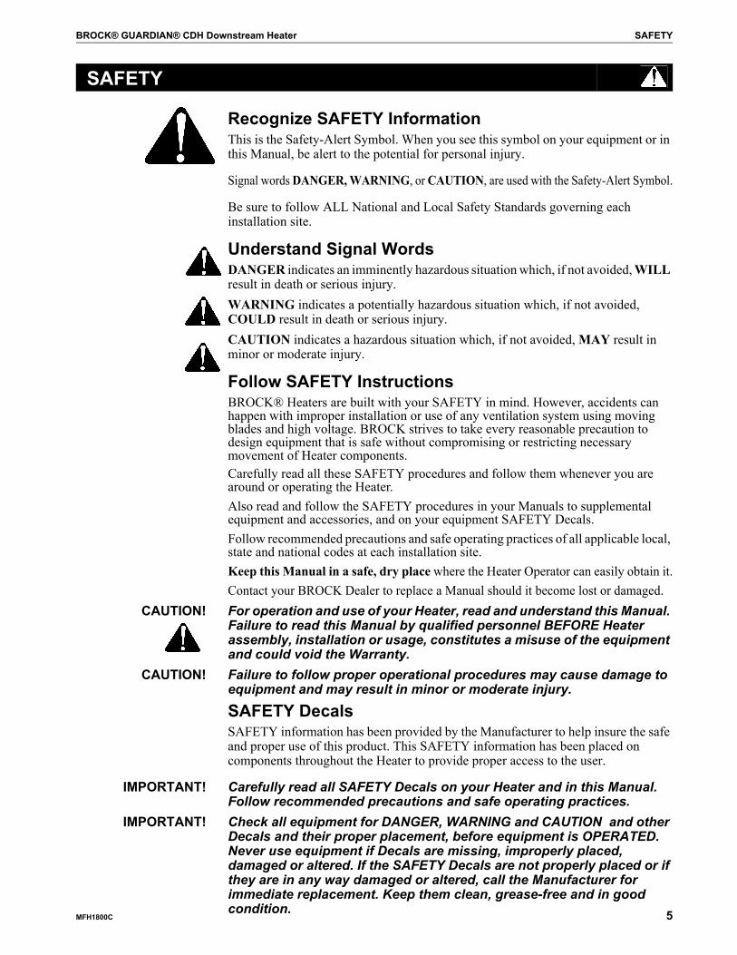
Recognize SAFETY InformationThis is the Safety-Alert Symbol. When you see this symbol on your equipment or in this Manual, be alert to the potential for personal injury.
Signal words DANGER, WARNING, or CAUTION, are used with the Safety-Alert Symbol.
Be sure to follow ALL National and Local Safety Standards governing each installation site.
Understand Signal WordsDANGER indicates an imminently hazardous situation which, if not avoided, WILL result in death or serious injury.WARNING indicates a potentially hazardous situation which, if not avoided, COULD result in death or serious injury.CAUTION indicates a hazardous situation which, if not avoided, MAY result in minor or moderate injury.
Follow SAFETY InstructionsBROCK® Heaters are built with your SAFETY in mind. However, accidents can happen with improper installation or use of any ventilation system using moving blades and high voltage. BROCK strives to take every reasonable precaution to design equipment that is safe without compromising or restricting necessary movement of Heater components.Carefully read all these SAFETY procedures and follow them whenever you are around or operating the Heater.Also read and follow the SAFETY procedures in your Manuals to supplemental equipment and accessories, and on your equipment SAFETY Decals.Follow recommended precautions and safe operating practices of all applicable local, state and national codes at each installation site.Keep this Manual in a safe, dry place where the Heater Operator can easily obtain it.Contact your BROCK Dealer to replace a Manual should it become lost or damaged.
CAUTION! For operation and use of your Heater, read and understand this Manual. Failure to read this Manual by qualified personnel BEFORE Heater assembly, installation or usage, constitutes a misuse of the equipment and could void the Warranty.
CAUTION! Failure to follow proper operational procedures may cause damage to equipment and may result in minor or moderate injury.
SAFETY DecalsSAFETY information has been provided by the Manufacturer to help insure the safe and proper use of this product. This SAFETY information has been placed on components throughout the Heater to provide proper access to the user.
IMPORTANT! Carefully read all SAFETY Decals on your Heater and in this Manual. Follow recommended precautions and safe operating practices.
IMPORTANT! Check all equipment for DANGER, WARNING and CAUTION and other Decals and their proper placement, before equipment is OPERATED. Never use equipment if Decals are missing, improperly placed, damaged or altered. If the SAFETY Decals are not properly placed or if they are in any way damaged or altered, call the Manufacturer for immediate replacement. Keep them clean, grease-free and in good condition.
SAFETY
SAFETY BROCK® GUARDIAN® CDH Downstream Heater
6 MFH1800C
.
SAFETY
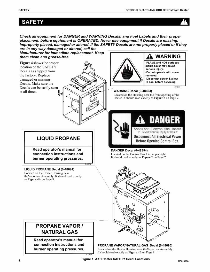
Check all equipment for DANGER and WARNING Decals, and Fuel Labels and their proper placement, before equipment is OPERATED. Never use equipment if Decals are missing, improperly placed, damaged or altered. If the SAFETY Decals are not properly placed or if they are in any way damaged or altered, call the Manufacturer for immediate replacement. Keep them clean and grease-free.Figure 4 shows the proper location of the SAFETY Decals as shipped from the factory. Replace damaged or missing Decals. Make sure the Decals can be easily seen at all times.
PROPANE VAPOR /NATURAL GAS
Read operator's manual for connection instructions and burner operating pressures.
0-48695
WARNING
0-48693
-FLAME and HOT surfaces inside cover may cause serious injury.-Do not operate with cover removed.-Disconnet power & allow to cool before servicing.
Figure 1. AXH Heater SAFETY Decal Locations
DANGER Decal (0-48354)Located on the Control Box Lid, upper right. It should read exactly as Figure 2 on Page 7.
WARNING Decal (0-48693)Located on the Housing near the front opening of the Heater. It should read exactly as Figure 3 on Page 9.
LIQUID PROPANE
Read operator's manual for connection instructions and burner operating pressures.
0-48694
LIQUID PROPANE Decal (0-48694)Located on the Heater Housing near theVaporizer Assembly. It should read exactly as Figure 4A on Page 8.
PROPANE VAPOR/NATURAL GAS Decal (0-48695)Located on the Heater Housing near theVaporizer Assembly. It should read exactly as Figure 4B on Page 8.
BROCK® GUARDIAN® CDH Downstream Heater SAFETY
MFH1800C 7
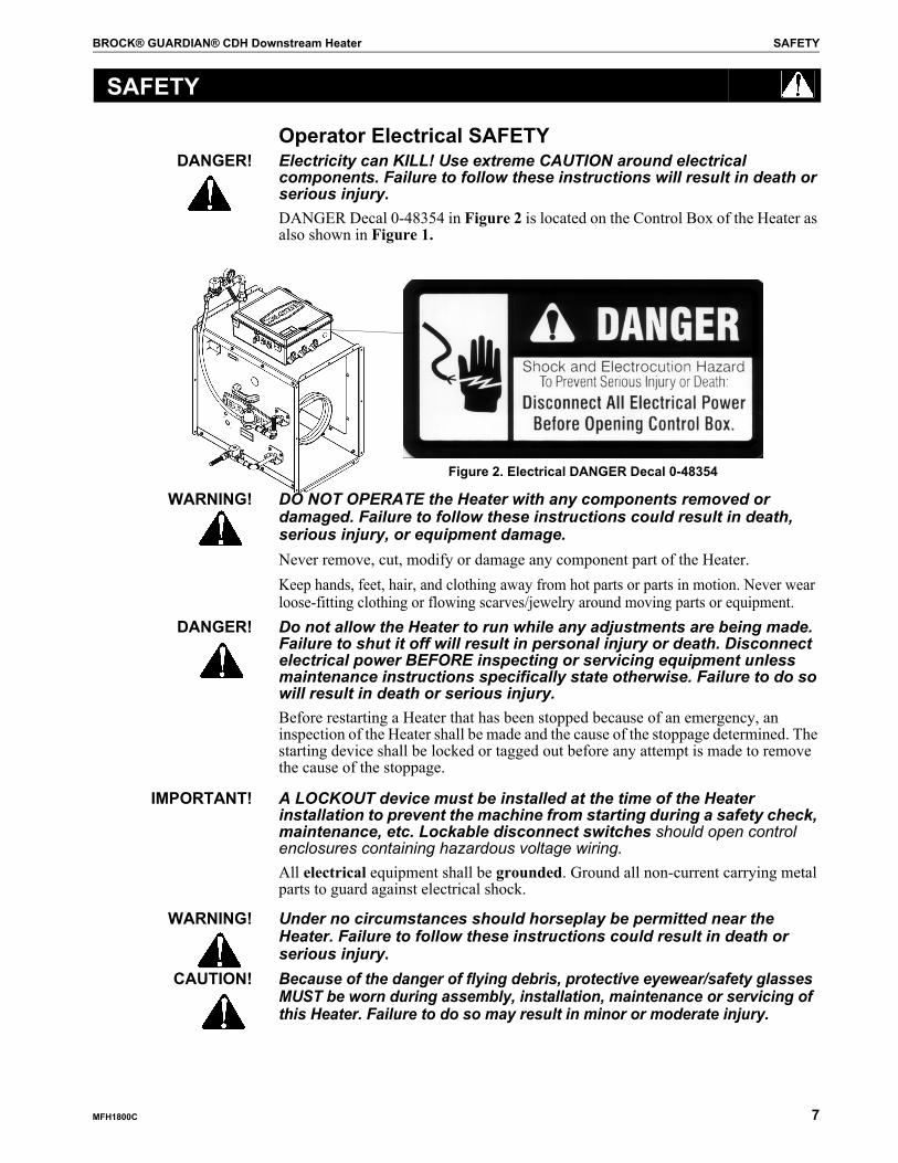
Operator Electrical SAFETY DANGER! Electricity can KILL! Use extreme CAUTION around electrical
components. Failure to follow these instructions will result in death or serious injury.DANGER Decal 0-48354 in Figure 2 is located on the Control Box of the Heater as also shown in Figure 1.
WARNING! DO NOT OPERATE the Heater with any components removed or damaged. Failure to follow these instructions could result in death, serious injury, or equipment damage.Never remove, cut, modify or damage any component part of the Heater.Keep hands, feet, hair, and clothing away from hot parts or parts in motion. Never wear loose-fitting clothing or flowing scarves/jewelry around moving parts or equipment.
DANGER! Do not allow the Heater to run while any adjustments are being made. Failure to shut it off will result in personal injury or death. Disconnect electrical power BEFORE inspecting or servicing equipment unless maintenance instructions specifically state otherwise. Failure to do so will result in death or serious injury.Before restarting a Heater that has been stopped because of an emergency, an inspection of the Heater shall be made and the cause of the stoppage determined. The starting device shall be locked or tagged out before any attempt is made to remove the cause of the stoppage.
IMPORTANT! A LOCKOUT device must be installed at the time of the Heater installation to prevent the machine from starting during a safety check, maintenance, etc. Lockable disconnect switches should open control enclosures containing hazardous voltage wiring. All electrical equipment shall be grounded. Ground all non-current carrying metal parts to guard against electrical shock.
WARNING! Under no circumstances should horseplay be permitted near the Heater. Failure to follow these instructions could result in death or serious injury.
CAUTION! Because of the danger of flying debris, protective eyewear/safety glasses MUST be worn during assembly, installation, maintenance or servicing of this Heater. Failure to do so may result in minor or moderate injury.
SAFETY
Figure 2. Electrical DANGER Decal 0-48354
SAFETY BROCK® GUARDIAN® CDH Downstream Heater
8 MFH1800C
Electrical Installation Requirements WARNING! Heater installations shall meet the National Fire Protection Association
Standard 61B for the prevention of fires and explosions in grain elevators and facilities handling bulk raw agricultural commodities. Failure to follow this standard could result in death or serious injury.In selecting electrical control equipment to be used with any installation, the purchaser must use equipment conforming to the National Electrical Code, the National Electrical Safety Code and other applicable local or national codes.
IMPORTANT! All electrical wiring should be done by a qualified electrician and all components must meet the National Fire Protection Association Standard NFPA No. 70, American National Standard Inst. ANSI-C1, and local requirements. BROCK assumes no responsibility for the electrical wiring used with this Heater. BROCK will not be liable for damage to the Heater because of improper electrical installation or use.
IMPORTANT! All Safety devices, including wiring of electrical devices shall be arranged to operate such that a power failure or failure of the device itself will not result in a hazardous condition.
CAUTION! To prevent a hazardous condition, the Heater MUST be prevented from restarting on its own after a power failure when power returns. Heater controls should be so arranged that, in case of emergency stop, manual resets or starts (at the location where the emergency stop initiated) shall be required for the Heater(s) and associated equipment to resume operation.
SAFETY
BROCK® GUARDIAN® CDH Downstream Heater SAFETY
MFH1800C 9
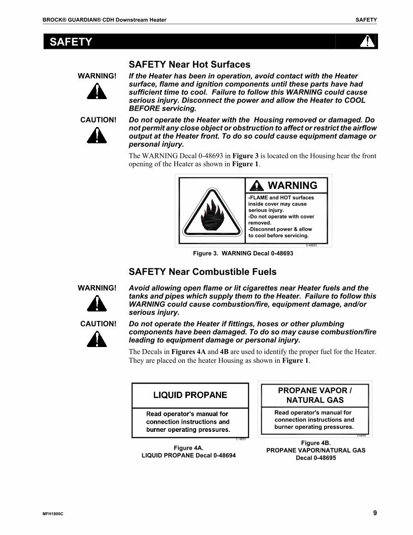
SAFETY Near Hot SurfacesWARNING! If the Heater has been in operation, avoid contact with the Heater
surface, flame and ignition components until these parts have had sufficient time to cool. Failure to follow this WARNING could cause serious injury. Disconnect the power and allow the Heater to COOL BEFORE servicing.
CAUTION! Do not operate the Heater with the Housing removed or damaged. Do not permit any close object or obstruction to affect or restrict the airflow output at the Heater front. To do so could cause equipment damage or personal injury.The WARNING Decal 0-48693 in Figure 3 is located on the Housing hear the front opening of the Heater as shown in Figure 1.
SAFETY Near Combustible FuelsWARNING! Avoid allowing open flame or lit cigarettes near Heater fuels and the
tanks and pipes which supply them to the Heater. Failure to follow this WARNING could cause combustion/fire, equipment damage, and/or serious injury.
CAUTION! Do not operate the Heater if fittings, hoses or other plumbing components have been damaged. To do so may cause combustion/fire leading to equipment damage or personal injury.The Decals in Figures 4A and 4B are used to identify the proper fuel for the Heater. They are placed on the heater Housing as shown in Figure 1.
SAFETY
WARNING
0-48693
-FLAME and HOT surfaces inside cover may cause serious injury.-Do not operate with cover removed.-Disconnet power & allow to cool before servicing.
Figure 3. WARNING Decal 0-48693
PROPANE VAPOR /NATURAL GAS
Read operator's manual for connection instructions and burner operating pressures.
0-48695
Figure 4A.LIQUID PROPANE Decal 0-48694
Figure 4B. PROPANE VAPOR/NATURAL GAS
Decal 0-48695
SAFETY BROCK® GUARDIAN® CDH Downstream Heater
10 MFH1800C
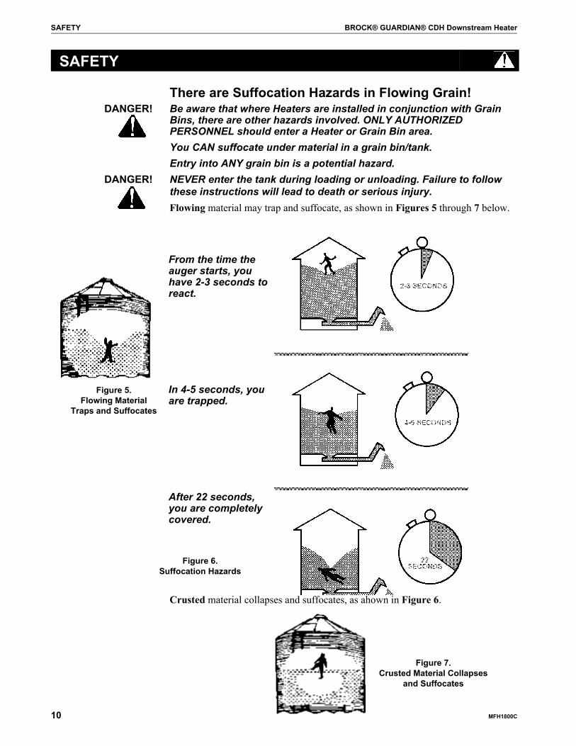
There are Suffocation Hazards in Flowing Grain!DANGER! Be aware that where Heaters are installed in conjunction with Grain
Bins, there are other hazards involved. ONLY AUTHORIZED PERSONNEL should enter a Heater or Grain Bin area. You CAN suffocate under material in a grain bin/tank.Entry into ANY grain bin is a potential hazard.
DANGER! NEVER enter the tank during loading or unloading. Failure to follow these instructions will lead to death or serious injury.Flowing material may trap and suffocate, as shown in Figures 5 through 7 below.
Crusted material collapses and suffocates, as ahown in Figure 6.
SAFETY
Figure 5. Flowing Material
Traps and Suffocates
From the time the auger starts, you have 2-3 seconds to react.
In 4-5 seconds, you are trapped.
After 22 seconds, you are completelycovered.
Figure 6. Suffocation Hazards
Figure 7. Crusted Material Collapses
and Suffocates

BROCK® GUARDIAN® CDH Downstream Heater About This Manual
MFH1800C 11
The intent of this Manual is to help you follow step-by-step instructions for identification and installation of your BROCK® AXH Heater.
IMPORTANT! Pay particular attention to all SAFETY Information in this Manual.CAUTION! For operation and use of your Heater, read and understand this Manual.
Failure to follow proper operational procedures may cause personal injury or equipment damage .Contact your BROCK Dealer to replace this Manual should it become lost or damaged.Warranty information is included on the inside front cover of this Manual.Motor choices and specifications are provided in the Parts Listing section at the back of this Manual.Major changes from the last printing will be listed on the back cover.Definition of Terms • This Planning Symbol is used in areas where planning needs to take place before
assembly and/or installation continue.• “Horizontal (-),” and “vertical ( ),” “bottom,” and “top” refer to the Heater as it
is standing.• “Right hand” (RH) and “left hand” (LH) terms are determined by facing in the
direction of the discharged airflow, i.e., the Inlet would be the RH side of the Heater, the Motor the LH side.
• Names for components and parts which have BROCK® Part Numbers have been capitalized throughout this Manual to call attention to them in the installation.
• Photographs may be of prototypes and could vary slightly from actual models. IMPORTANT! Some Heater Guards have been removed for illustrative purposes only.
MeasurementsThe symbols ('') equals inches and (') equals feet in English measurements.Metric measurements are shown in millimeters and square brackets following the English measurement, unless otherwise specified. For example: 15' [4 572]90' [27 432]Metric equivalents are listed after the English measurement and not always repeated throughout the Manual. These units of measurement are also used:• (“) or in -inches• (‘) or ft -feet• inlb - inch lb• ftlb - foot pounds (12 inlbs)• inlb - inch pounds • cfm - cubic feet per minute• inwc - inches water column• sqft - square feet• A - amps or amperes• FLA -full load amps• V - volts• Ph - phase• psi - pounds per square inch• btu/hr - British thermanl Units per hour• MMbtu/hr - million btu per hour• gal/hr - gallons per hour• cfh - cubic feet per hour
About This Manual

About This Manual BROCK® GUARDIAN® CDH Downstream Heater
12 MFH1800C
Identification of Parts and HardwareIMPORTANT! No hardware substitutions are permitted unless noted.
Diagrams are provided throughout this Manual to identify Parts and Hardware used in that application. • Parts and basic components are identified in Figures and their accompanying
Tables as “Items” with a black number in white circle.• Hardware (and hardware connections between Parts) are identified with a white
number in a shaded circle. See Figure 8. Hardware Item numbers are listed after the Parts in a Figure Table.
• Dimensions and lengths are noted with a white circle on an arrow or line, then identified with numeric values in a Figure Table.
• Very small numbers near an illustration (i.e., 1257-48) are identification of the graphic, not a Part Number.
Plumbing Fittings Identification
32
16
7
5Item Description
1 Locking Hex Nut2 Hex Nut3 Flange Nut4 Flange Head Bolt5 Bin Seal Bolt6 Gr 8 Hex Head Cap Screw7 Gr 5 Hex Head Cap Screw8 Gr 5 Carriage Bolt
11 Hardware/Part ConnectionParts
Figure 8. Hardware Identification
8
4
1 23
4 5 6
Nominal Schl 40 Schl 80Pipe Size OD Wall Wall
1/8 0.405 0.068 0.0951/4 0.540 0.088 0.1193/8 0.675 0.091 0.1261/2 0.840 0.109 0.1473/4 1.050 0.113 0.1541 1.315 0.133 0.179
1 1/4 1.660 0.140 0.1911 1/2 1.900 0.145 0.200
Item Description1 Elbow 90°2 Elbow 45°3 Tee4 Nipple5 Adapter6 Bushing
Figure 9. Plumbing Fittings Identification

BROCK® GUARDIAN® CDH Downstream Heater Heater Parts Identification
MFH1800C 13
General Heater
Heater Parts Identification
Item Description1 Housing 2 Coil, Vaporizer (p. 38)3 Regulator assembly (pp. 37-38)4 Intake Plumbing Assembly (pp. 37-38)5 Fitting, Conduit 1/2''6 Decal, PV/N Fuel Supply (pp. 6,9)7 Decal, BROCK® 16''8 Handle, Plastic (pp. 34-35)9 Plate, Serial Number (pp. 34-35)
10 Hose, LP (p. 38)11 Adapter, 3/4 npt x 1/2 msae Elbow (p. 38)12 Assembly, Standard Plumbing (p. 36)13 Gauge (p. 36)14 Control Box Assembly (pp. 14, 41)15 Decal, DANGER 0-48354 (pp. 6,7)16 Access Panel (pp. 34-35)17 Decal, WARNING 0-48693 (pp. 6,9)18 Burner Assembly (pp. 39-40)
Figure 10. CDH Downstream Heater
3
10
WARNING
0-48693
-FLAME and HOT surfaces inside cover may cause serious injury.-Do not operate with cover removed.-Disconnet power & allow to cool before servicing.
END VIEW45
8 8
18
1
2
1112
13
1417
CONTROL
MINPSI
MAXMMbtu/hr
VOLTSMINMMbtu/hr
Brock ManufacturingMilford, IN
SUPPLY PRES
INPUT RATE
FUEL TYPE
MODEL
SN
0-48691
BURNER PRES MINPSI
MAXPSI
MAXPSI
15
2
16
1
3
4
108
7
12
11 13
14
9
*
Heater Parts Identification BROCK® GUARDIAN® CDH Downstream Heater
14 MFH1800C
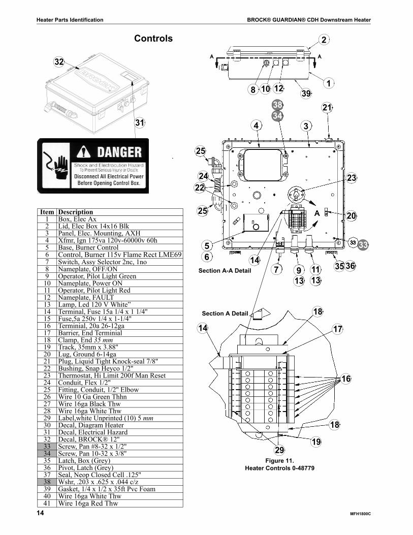
Controls
Figure 11. Heater Controls 0-48779
20
76
Section A Detail
Section A-A Detail
Item Description1 Box, Elec Ax2 Lid, Elec Box 14x16 Blk3 Panel, Elec. Mounting, AXH4 Xfmr, Ign 175va 120v-60000v 60h5 Base, Burner Control6 Control, Burner 115v Flame Rect LME697 Switch, Assy Selector 2nc, 1no8 Nameplate, OFF/ON9 Operator, Pilot Light Green
10 Nameplate, Power ON11 Operator, Pilot Light Red12 Nameplate, FAULT13 Lamp, Led 120 V White”14 Terminal, Fuse 15a 1/4 x 1 1/4''15 Fuse,5a 250v 1/4 x 1-1/4''16 Terminial, 20a 26-12ga17 Barrier, End Terminial18 Clamp, End 35 mm19 Track, 35mm x 3.88''20 Lug, Ground 6-14ga21 Plug, Liquid Tight Knock-seal 7/8''22 Bushing, Snap Heyco 1/2''23 Thermostat, Hi Limit 200f Man Reset24 Conduit, Flex 1/2''25 Fitting, Conduit, 1/2'' Elbow26 Wire 10 Ga Green Thhn27 Wire 16ga Black Thw28 Wire 16ga White Thw29 Label,white Unprinted (10) 5 mm30 Decal, Diagram Heater31 Decal, Electrical Hazard32 Decal, BROCK® 12''33 Screw, Pan #8-32 x 1/2''34 Screw, Pan 10-32 x 3/8''35 Latch, Box (Grey)36 Pivot, Latch (Grey)37 Seal, Neop Closed Cell .125''38 Wshr, .203 x .625 x .044 c/z39 Gasket, 1/4 x 1/2 x 35ft Pvc Foam40 Wire 16ga White Thw41 Wire 16ga Red Thw
23
514
913
1113
35 36
33
25
34
2224
25
213834
14
18
17
16
18
1929
31
32
1
2
398 10 12

BROCK® GUARDIAN® CDH Downstream Heater Pre-Installation Planning
MFH1800C 15
Tools and Equipment NeededWARNING! Inventory all tools and pieces of hardware near the Heater during
installation or servicing. Tools left inside in the Heater could cause personal injury or equipment damage.
• Flat-blade screwdriver• Saw and blades to cut Heater opening in metal transition• 1/2" open end wrenches/Socket wrenches with 1/2'' socket• 5/16'' open-end wrench or a 12-point 3/8'' socket and ratchet• Hammer• Wire cutters and wire strippers• Pipe wrench• Adjustable wrench• Pipe sealant• Leak detection solution (soak solution)• 12'' drift punch for aligning holes with Transition• Drill bits• Tape measure
Heater InspectionDANGER! Electricity can kill! Inspections MUST be done with the MAIN POWER
LOCKED OUT. • Check all fasteners for tightness.• Check inside the Heater Housing for loose objects.• Inspect electrical controls and wire connections for tightness.• Retighten any loose hardware, and/or electrical fittings. • Make a note of your Serial Number and other specifications for your Heater,
found on the Serial Number Identification Plate (Item 9 on Page13). Write the information in the blanks on Page 4 of this Manual for quick reference.
VentingAdequately vent your Bin roof to prevent Heater back pressure. For good Heater performance, the bin should have an exhausted area equal to 1 sq. ft. for each 1500 cfm airflow rate.
Pre-Installation Planning
Pre-Installation Planning BROCK® GUARDIAN® CDH Downstream Heater
16 MFH1800C
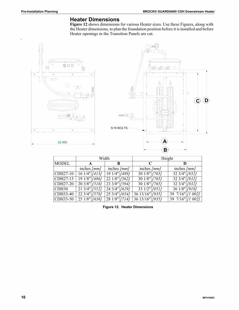
Heater DimensionsFigure 12 shows dimensions for various Heater sizes. Use these Figures, along with the Heater dimensions, to plan the foundation position before it is installed and before Heater openings in the Transition Panels are cut.
.
Width HeightMODEL A B C D
inches [mm] inches [mm] inches [mm] inches [mm]CDH27-10 16 1/4'' [413] 19 1/4'' [489] 30 1/8'' [765] 32 3/4'' [832]CDH27-15 19 1/8'' [486] 22 1/8'' [562] 30 1/8'' [765] 32 3/4'' [832]CDH27-20 20 3/8'' [518] 23 3/8'' [594] 30 1/8'' [765] 32 3/4'' [832]CDH30 21 3/4'' [552] 24 3/4'' [629] 33 1/2'' [851] 36 1/8'' [918]CDH33-40 22 3/4'' [578] 25 3/4'' [654] 36 13/16'' [935] 39 7/16'' [1 002]CDH33-50 25 1/8'' [638] 28 1/8'' [714] 36 13/16'' [935] 39 7/16'' [1 002]
Figure 12. Heater Dimensions
AB
C D
BROCK® GUARDIAN® CDH Downstream Heater Pre-Installation Planning
MFH1800C 17
Bin and Transition InspectionThe bin should be well sealed to prevent air loss from the plenum or the ductwork below the grain. Caulk all joints, seams, and applicable bin foundation connections to prevent air leakage at or under the Heater connection or drying Floor.The Heater Transition should be installed to minimize airflow restriction. The air entrance needs be as clear as possible from Floor Supports. Use all sealant, caulk or gaskets which the manufacturer recommends.A properly fitting, gradually angled Heater Transition is necessary to connect your Heater to the opening in the Bin.
IMPORTANT! Do NOT use anything for a Transition that would severely angle or disrupt airflow from the Heater into the bin.Ask your BROCK® Dealer about BROCK® Heater Transitions. If your BROCK® Transition has already been ordered, you will need to assemble it using the one of the following Manuals: • LOW Transition with 38'' h x 33'' w [965 x 838] Heater Backplate: 9-39788 for
Narrow (2.67'') Corrugated Bins and 9-46450 for (4'') Wide Corrugated Bins: BROCK® Instruction MGB1499.
• AERATION Transition (9-39786) for Narrow (2.67'') Corrugated Bins: BROCK® Instruction MGB1500.
• HIGH Transition (9-39787) for Narrow (2.67'') Corrugated Bins: BROCK® Instruction MGB1501.

Pre-Installation Planning BROCK® GUARDIAN® CDH Downstream Heater
18 MFH1800C
Foundation/Concrete Pad IMPORTANT! The Heater (and Fan) should be mounted on a level concrete pad that
has been poured at a height determined by the Transition manufac-turer's instructions. DO NOT ATTACH the Fan or Heater to the pad. The Fan and Heater need to have the ability to move freely, therefore not putting the Transition in a bind. See Figure 15.See the Heater Dimensions in Figure 12 for suggested Foundation size. Note that the foundation is wider on the Motor side of the Heater, not centered on the Transition centerline.
Figure 13. Heater Installation at Bin
2
1
4
5 6 3
LEFT SIDE VIEW
DIRECTION OF AIR FLOW
TOP VIEW
1
2
3
4
5
6
DIR
EC
TION
OF
AIR FLO
W
24
51
3
6 Item Description1 Bin Sidewall2 Bin Foundation3 Fan Transition4 Fan Pad5 Axial Fan6 AXH Heater
BROCK® GUARDIAN® CDH Downstream Heater Electrical Installation
MFH1800C 19
Wiring SAFETY RemindersDANGER! Electricity can kill! All electrical wiring MUST be done by a certified/
licensed electrician. All components must meet the National Fire Protection Association Standard NFPA No. 70, American National Standard Inst. ANSI-C1, and applicable national, state and local electrical SAFETY codes.
WARNING! Heater installations shall meet the National Fire Protection Association Standard 61B for the prevention of fires and explosions in grain elevators and facilities handling bulk raw agricultural commodities. Failure to follow this standard could result in death or serious injury.In selecting electrical control equipment to be used with any installation, the purchaser must use equipment conforming to the National Electrical Code, the National Electrical Safety Code and other applicable local or national codes. Follow all applicable local, state and national electrical codes for wiring.
Heater controls should be so arranged that, in case of emergency stop, manual resets or starts (at the location where the emergency stop initiated) shall be required for the Heater(s) and associated equipment to resume operation.
BROCK assumes no responsibility for the electrical wiring used with this Heater. BROCK will not be liable for damage to the Heater because of improper electrical installation or use.
IMPORTANT! All SAFETY devices, including wiring of electrical devices shall be arranged to operate such that a power failure or failure of the device itself will not result in a hazardous condition.
CAUTION! To prevent a hazardous condition, the Heater MUST be prevented from restarting on its own after a power failure when power returns.Install an electric disconnect within reach of each Heater.
CAUTION! Do not jeopardize your BROCK® Heater Warranty with improper electrical installation!
Electrical Installation

Electrical Installation BROCK® GUARDIAN® CDH Downstream Heater
20 MFH1800C
Electrical ConnectionControl power - The Heater is designed for 115v connections. If the Fan does not have 115v controls, a 250va step-down Transformer may be required to reduce the control voltage. Consult the Fan manufacturer for recommendations.
Control Transformer size - 380, 460v, and 575v GUARDIAN® Series BROCK® Fans are equipped with a 100va control Transformer. It must be changed to a 250va transformer to carry the Heater load.
Power InterlockingConnect the Heater Power Conduit to the Fan Control Box. In the Fan Control Box, connect the:• Black wire to 115v interlocked power, Terminal #7 in BROCK® Fans.• White neutral wire to neutral, Terminal #2 in BROCK® Fans.• Green ground wire to the ground lug in the Fan Control Box.
WARNING! Connect only to a 115v electrical control source, which is interlocked to the Fan Motor. The Heater power must shut off when the Fan Motor is not operating for any reason. If the Fan Motor is wired with internal thermo protection, it must be wired so that the power to the contactor and the Heater is removed when the thermo device trips. If these instructions are not followed, equipment damage and/or personal injury could result.
380 460 575Transformer PN 0-48244 0-48240 0-48242
Voltage
0-48876
Figure 14. Fan Control
Figure 15. Heater Control
OVERLOAD ADJUSTMENT OVERLOAD RESETAUXILIARY CONTACTS
CONTROL FUSE, 2ATERMINAL #7
TERMINAL #2, NEUTRAL
BROCK® GUARDIAN® CDH Downstream Heater Electrical Installation
MFH1800C 21
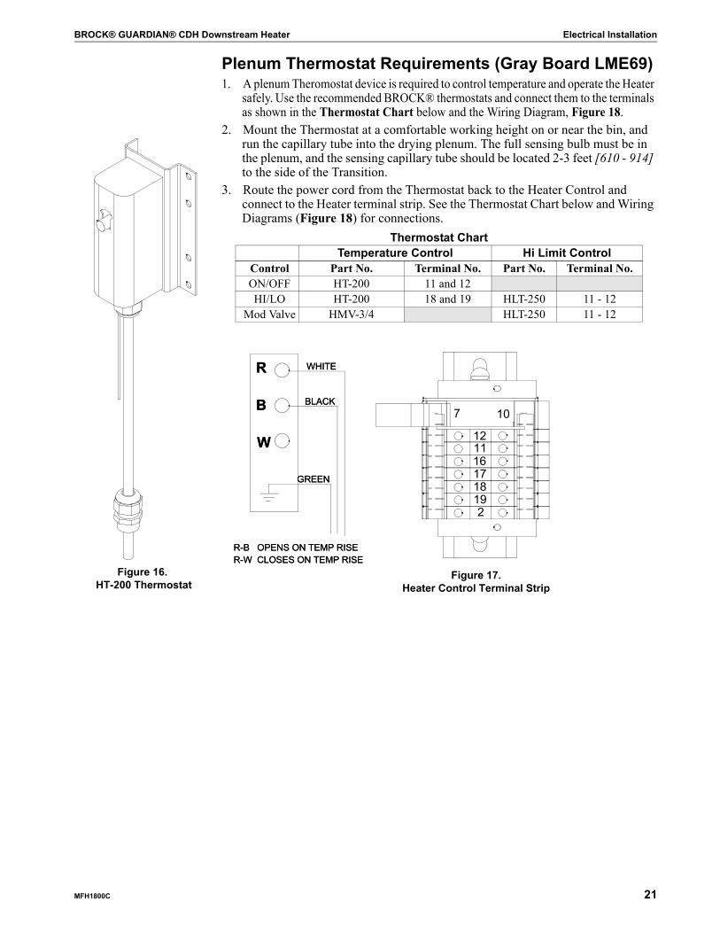
Plenum Thermostat Requirements (Gray Board LME69)1. A plenum Theromostat device is required to control temperature and operate the Heater
safely. Use the recommended BROCK® thermostats and connect them to the terminals as shown in the Thermostat Chart below and the Wiring Diagram, Figure 18.
2. Mount the Thermostat at a comfortable working height on or near the bin, and run the capillary tube into the drying plenum. The full sensing bulb must be in the plenum, and the sensing capillary tube should be located 2-3 feet [610 - 914] to the side of the Transition.
3. Route the power cord from the Thermostat back to the Heater Control and connect to the Heater terminal strip. See the Thermostat Chart below and Wiring Diagrams (Figure 18) for connections.
Thermostat ChartTemperature Control Hi Limit Control
Control Part No. Terminal No. Part No. Terminal No.ON/OFF HT-200 11 and 12HI/LO HT-200 18 and 19 HLT-250 11 - 12
Mod Valve HMV-3/4 HLT-250 11 - 12
R
B
W
R-B OR-W C
R
B
W
R-B OR-W CFigure 16.
HT-200 Thermostat
R
B
W
GREEN
WHITE
BLACK
R-B OPENS ON TEMP RISER-W CLOSES ON TEMP RISE
R
B
W
GREEN
WHITE
BLACK
R-B OPENS ON TEMP RISER-W CLOSES ON TEMP RISE
HITE
ACK
HITE
ACK
107
2191817161112
Figure 17.Heater Control Terminal Strip

Electrical Installation BROCK® GUARDIAN® CDH Downstream Heater
22 MFH1800C
Figure 18. 0-48714 Wiring
Heater Wiring Diagram

BROCK® GUARDIAN® CDH Downstream Heater Gas Connection
MFH1800C 23
General1. Gas connections should be made by a qualified gas service person according to
local fuel code for the appropriate fuel connection.2. When using propane fuel, be sure the Tank is located away from the Burner the
minimum distance required by all applicable local, state and national codes. Consult your fuel supplier.
3. Check all installations for leaks using a soap solution. Correct problems before operating equipment.
4. The Heater unit is equipped with a liquid-filled Gauge. On certain brands, it is necessary to open the Vent Valve on top of the Gauge to obtain accurate readings. Check the instructions on the Gauge for this procedure.
Liquid Propane1. Liquid propane models are equipped with an internal Vaporizer and should be
connected to the propane tank for liquid draw.2. Be sure that line size is adequate and line restrictions are minimized to prevent
pre-vaporization. See fuel specifications in the Fuel Specifications Chart on Pages 29-30. Do not use a pressure regulator in the liquid supply line.
3. Be sure propane supply tanks are clean. Tanks that have been used for vapor draw may contain oils which must be purged. Tanks that have previously been used for ammonia must be properly purged and converted. Consult your fuel supplier.
4. The customer must supply a fuel shutoff and strainer just ahead of the connection to the 1/4'' npt liquid solenoid valve on the Heater.
Propane Vapor1. N/PV models can be operated on either natural gas or propane vapor. They are
shipped from the factory with the propane vapor orifice installed. A larger natural gas orifice is attached to the shutoff valve and should removed from the unit.
2. For propane vapor operation, connect to the propane supply tank for vapor draw or to an external vaporizer unit. The tank size must be large enough to provide adequate fuel vaporization capacity to supply the Burner rate. The vaporization capacity will vary with ambient temperature. Consult your fuel supplier.
3. A fuel pressure regulator must be installed at the tank to reduce pressure to a range of 10-15 psi.
4. A shutoff valve is supplied on the Heater unit. The customer should supply a fuel strainer at the 3/4'' npt valve connection.
Natural Gas1. N/PV models can be operated on either natural gas or propane vapor. They are
shipped from the factory with the propane vapor orifice installed. A larger natural gas orifice is attached to the shutoff valve and must be installed before operation.
2. Be sure that line size is adequate and line restrictions are minimized. See fuel specifications in the Fuel Specifications Chart on Pages 29-30.
3. A shutoff valve is supplied on the Heater unit. The customer should supply a fuel strainer at the 3/4'' npt valve connection.
Gas Connection

Operation: Initial Startup Checks BROCK® GUARDIAN® CDH Downstream Heater
24 MFH1800C
Initial Startup CheckDANGER! Electricity can kill! Startup inspections MUST be done with the MAIN
POWER LOCKED OUT. Failure to follow these instructions will result in serious injury or death.
IMPORTANT! With MAIN POWER LOCKED OUT, inspect electrical controls and wire connections for TIGHTNESS.Turn Main Power ON and check control voltage before starting the unit to prevent possible damage to controls.
CAUTION! DO NOT OPERATE the Heater on an empty bin. To do so can sometimes dislodge floor supports.Disconnect Main Power when tests are completed.
Fan and Heater Pre-Check1. Initial inspection must be done with the main power locked out and gas supply
turned OFF.2. Check Fan and Heater unit for any loose hardware or any obstructions inside or
outside the housing. 3. Check electrical controls for any loose wiring.4. Turn gas ON and check for any leaks from the supply to the Heater Solenoid Valve.5. Be sure that the bin roof vents are open.
CAUTION! DO NOT OPERATE the Fan on an empty bin. To do so can sometimes dislodge Floor Supports.
Heater Control Lockout Check1. Turn main electrical power ON. With Heater Selector Switch in the OFF
position, check the Fan for proper rotation.
WARNING! Check the Fan for proper rotation. Refer to your Fan Manual. Incorrect rotation may cause flame to be pulled into the Fan Motor and may cause damage to the Fan and Heater units.2. With the gas still OFF, and with the Fan running, turn the Burner Switch to ON.
The green POWER ON light should illuminate, indicating that the Thermostat is connected and the Flame Control is powered.
3. In twenty-five (25) seconds, the Solenoid Valves should open. A spark should be observed through the RH Inspection Port.
4. In ten (10) seconds, the spark should go off, the Solenoid Valves close and the Burner should lockout as indicated by the red FAULT light.
Operation: Initial Startup Checks
OFF ON POWER ON FAULT
Figure 19. Heater Control Location

BROCK® GUARDIAN® CDH Downstream Heater Operation: Initial Startup Checks
MFH1800C 25
Ignition Check1. Turn the Gas Valve ON and reset the Burner by holding down the illuminated
button on the LME 69 board. Hold down for one (1) second but less than three (3) seconds. After the button is pressed, the light will change from solid red to a solid yellow and will start the purge and trial for ignition cycles. If you hold the button down for three (3) seconds or longer, the LME 69 board will go into a diagnostic mode, which is shown by a fast flashing red light. To get out of this diagnostic mode, press the button again for three (3) seconds to return to normal cycle.
2. In twenty-five (25) seconds the Solenoids should open; a pressure should be indicated on the Pressure Gauge and ignition should take place. Be sure to immediately set the Burner pressure to the appropriate operating range for the Heater. See the Fuel Specifications Chart.
Plenum Temperature Controlling Thermostat Check1. Turn the Thermostat down. The Heater should turn off for ON/OFF control or
decrease to low pressure for HI/LO Control. Set the LO pressure to the appropriate value at this time (approximately 1/2 to 1/3 the high pressure setting, but not lower than the minimum operating pressure shown in the Fuel Specifications Chart on Pages29-30). Too low of a setting will cause the Burner to lockout or fail to ignite.
2. Turn the Thermostat up. The Burner should relight for ON/OFF control or should go to high fire for HI/LO control.
Hi-Limit Thermostat Check1. On units equipped with HLT-250 High Limit Controls, turn the setting down.
Then the Heater should shut off. 2. Turn the HLT Thermostat setting up. The green POWER ON Light should not
come on, and the Heater will not relight.3. Push the HLT Thermostat Manual Reset Button. The Heater green POWER ON
Light should illuminate and begin a new ignition cycle.
Fan and Heater Shut Down1. With the Burner operating, shut off the fuel supply at the source. On propane
tanks, shut off at the tank and allow the fuel to burn out of the line. The Burner will lockout.
2. Turn the Burner Switch OFF.3. Turn the Fan OFF.4. Disconnect the main electrical power.
Operation BROCK® GUARDIAN® CDH Downstream Heater
26 MFH1800C
DANGER! DO NOT OPERATE the Heater with the Guard off. Failure to follow these instructions will result in death or serious injury.Severe personal injury may result if equipment is operated without the Guard properly installed/latched.
DANGER! Do not allow the Heater to run while any adjustments are being made. Failure to shut it off will lead to personal injury or death. Disconnect electrical power BEFORE inspecting or servicing equipment unless maintenance instructions specifically state otherwise. Failure to do so will result in death or serious injury.Before restarting a Heater that has been stopped because of an emergency, an inspection of the Heater shall be made and the cause of the stoppage determined. The starting device shall be locked or tagged out before any attempt is made to remove the cause of the stoppage.
Flame Control
The Burner Control has the following cycles:
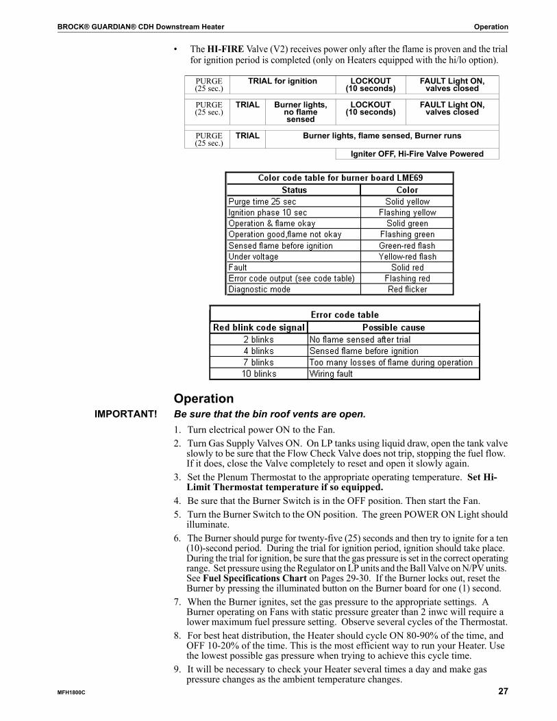
• The PURGE time of twenty-five (25) seconds clears any accumulated gas from the Heater and Drying Plenum prior to ignition. It begins when the Fan is run-ning, the Burner Switch is ON, the Housing High Limit Thermostat is closed, and the Thermostat is calling for heat. The green POWER ON Light indicates these conditions are satisfied (Terminal 12 has 115v power). After the tempera-ture requirement has been achieved, the Heater will shut off. When the thermo-stat again calls for heat, the PURGE cycle will be skipped and will go directly into the TRIAL for ignition cycle.During the PURGE time the LME 69 board will show a solid yellow light.
• The TRIAL for ignition is allowed for ten (10) seconds. During this period, the Igniter, Vapor Valve (V1), and Liquid Valve (LV) are powered. Ignition should take place during this period.During the TRIAL for ignition time, the LME 69 board will show a flashing yellow light.
• LOCKOUT occurs if a flame is not sensed for any consecutive (10) ten-second period following the TRIAL cycle. The red FAULT Light will indicate a lockout and all Solenoid Valves will close. The green POWER ON Light will still be illuminated.During LOCKOUT the LME 69 board will show a solid red light.
• RESET the Control by holding down the illuminated button on the LME 69 board. Hold down for one (1) second but less than three (3) sconds. After the button is pressed, the light will change from solid red to a solid yellow and will start the PURGE and TRIAL for ignition cycles. If you hold down for three (3) seconds or longer, the LME 69 board will go into a diagnostic mode which is shown by a fast flashing red light. To get out of his diagnostic mode, press the button again for three (3) seconds to return to normal cycle.
Operation
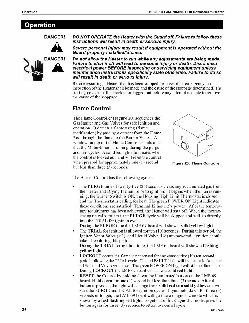
Figure 20. Flame Controller
The Flame Controller (Figure 20) sequences the Gas Igniter and Gas Valves for safe ignition and operation. It detects a flame using (flame rectification) by passing a current from the Flame Rod through the flame to the Burner Vanes. A window on top of the Flame Controller indicates that the Motor/timer is running during the purge and trial cycles. A solid red light illuminates when the control is locked out, and will reset the control when pressed for approximately one (1) second but less than three (3) seconds.
BROCK® GUARDIAN® CDH Downstream Heater Operation
MFH1800C 27
• The HI-FIRE Valve (V2) receives power only after the flame is proven and the trial for ignition period is completed (only on Heaters equipped with the hi/lo option).
OperationIMPORTANT! Be sure that the bin roof vents are open.
1. Turn electrical power ON to the Fan.2. Turn Gas Supply Valves ON. On LP tanks using liquid draw, open the tank valve
slowly to be sure that the Flow Check Valve does not trip, stopping the fuel flow. If it does, close the Valve completely to reset and open it slowly again.
3. Set the Plenum Thermostat to the appropriate operating temperature. Set Hi-Limit Thermostat temperature if so equipped.
4. Be sure that the Burner Switch is in the OFF position. Then start the Fan.5. Turn the Burner Switch to the ON position. The green POWER ON Light should
illuminate.6. The Burner should purge for twenty-five (25) seconds and then try to ignite for a ten
(10)-second period. During the trial for ignition period, ignition should take place. During the trial for ignition, be sure that the gas pressure is set in the correct operating range. Set pressure using the Regulator on LP units and the Ball Valve on N/PV units. See Fuel Specifications Chart on Pages 29-30. If the Burner locks out, reset the Burner by pressing the illuminated button on the Burner board for one (1) second.
7. When the Burner ignites, set the gas pressure to the appropriate settings. A Burner operating on Fans with static pressure greater than 2 inwc will require a lower maximum fuel pressure setting. Observe several cycles of the Thermostat.
8. For best heat distribution, the Heater should cycle ON 80-90% of the time, and OFF 10-20% of the time. This is the most efficient way to run your Heater. Use the lowest possible gas pressure when trying to achieve this cycle time.
9. It will be necessary to check your Heater several times a day and make gas pressure changes as the ambient temperature changes.
PURGE(25 sec.)
TRIAL for ignition LOCKOUT(10 seconds)
FAULT Light ON, valves closed
PURGE(25 sec.)
TRIAL Burner lights, no flame sensed
LOCKOUT(10 seconds)
FAULT Light ON, valves closed
PURGE(25 sec.)
TRIAL Burner lights, flame sensed, Burner runs
Igniter OFF, Hi-Fire Valve Powered
Operation BROCK® GUARDIAN® CDH Downstream Heater
28 MFH1800C
ControlsON/OFF Control - The Burner should periodically cycle ON and OFF. Increasing the fuel pressure will reduce the percentage of ON time. Reducing the fuel pressure will increase the percentage of ON time. If the Burner is ON all the time, the Thermostat temperature is not being satisfied and the fuel pressure should be increased.
IMPORTANT! DO NOT EXCEED the maximum operating fuel pressure shown in the Fuel Specifications Chart beginning on the opposite Page.HI-LO Control - The Burner should periodically cycle from a hi-fire to low fire. • Set the high fire pressure using the regulator on LP units or the Ball Valve on
Natural Gas and Propane Vapor units. Increasing the Hi fuel pressure will reduce the percentage of High fire time. Reducing the fuel pressure will increase the percentage of High fire time. If the Burner is in Hi-Fire all the time, the Thermostat temperature is not being satisfied and the high fire fuel pressure should be increased. Do not exceed the maximum operating fuel pressure shown in the Fuel Specifications Chart.
• The low fire fuel pressure is set using the Bypass Needle Valve on the Hi-Lo Valve. The typical setting is 1/2 to 1/3 the setting of the high fire pressure. If the Burner is in low fire all the time, the low fire fuel pressure is set too high and should be reduced.
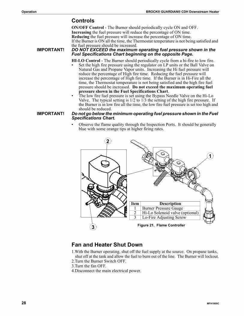
IMPORTANT! Do not go below the minimum operating fuel pressure shown in the Fuel Specifications Chart. • Observe the flame quality through the Inspection Ports. It should be generally
blue with some orange tips at higher firing rates.
Fan and Heater Shut Down1.With the Burner operating, shut off the fuel supply at the source. On propane tanks,
shut off at the tank and allow the fuel to burn out of the line. The Burner will lockout.2.Turn the Burner Switch OFF.3.Turn the fan OFF.4.Disconnect the main electrical power.
Item Description1 Burner Pressure Gauge2 Hi-Lo Solenoid valve (optional)3 Lo-Fire Adjusting Screw
Figure 21. Flame Controller
1
2
3
BROCK® GUARDIAN® CDH Downstream Heater Operation
MFH1800C 29
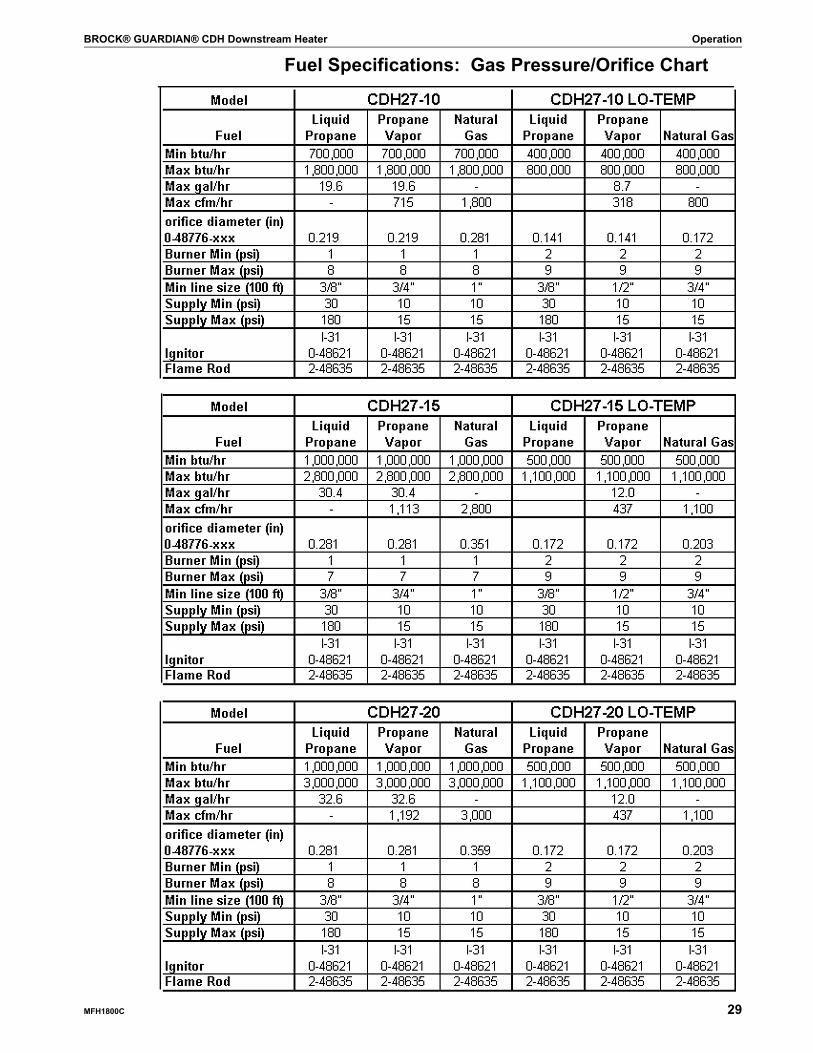
Fuel Specifications: Gas Pressure/Orifice Chart
Operation BROCK® GUARDIAN® CDH Downstream Heater
30 MFH1800C
BROCK® GUARDIAN® CDH Downstream Heater Maintenance and Service
MFH1800C 31
SAFETY RemindersService and maintenance of Heaters must be done only by a qualified technician.
DISCONNECT POWER prior to maintaining or cleaning the Heater!DANGER! Electricity can kill! Inspections MUST be done with the MAIN POWER
LOCKED OUT. Failure to follow these instructions (allowing the Heater to start automatically) will result in serious injury or death.
CAUTION! Because of the danger of falling or flying debris, protective eyewear/safety glasses MUST be worn during assembly, installation, maintenance or servicing of this Heater. Failure to do so may result in minor or moderate injury.
Yearly Startup ChecksDANGER! Electricity can kill! Yearly startup checks MUST be done with the MAIN
POWER LOCKED OUT. Failure to follow these instructions will result in serious injury or death.
CAUTION! Because of the danger of falling or flying debris, protective eyewear/safety glasses MUST be worn during assembly, installation, maintenance or servicing of this Heater. Failure to do so may result in minor or moderate injury.• Check the Heater-transition-bin connection for proper seal. Replace any caulk-
ing or gasket as needed.• Check electrical components and connections.• Check bin roof doors for any obstructions that would cause ventilation restrictions.
Maintenance and Service
Trouble Shooting BROCK® GUARDIAN® CDH Downstream Heater
32 MFH1800C
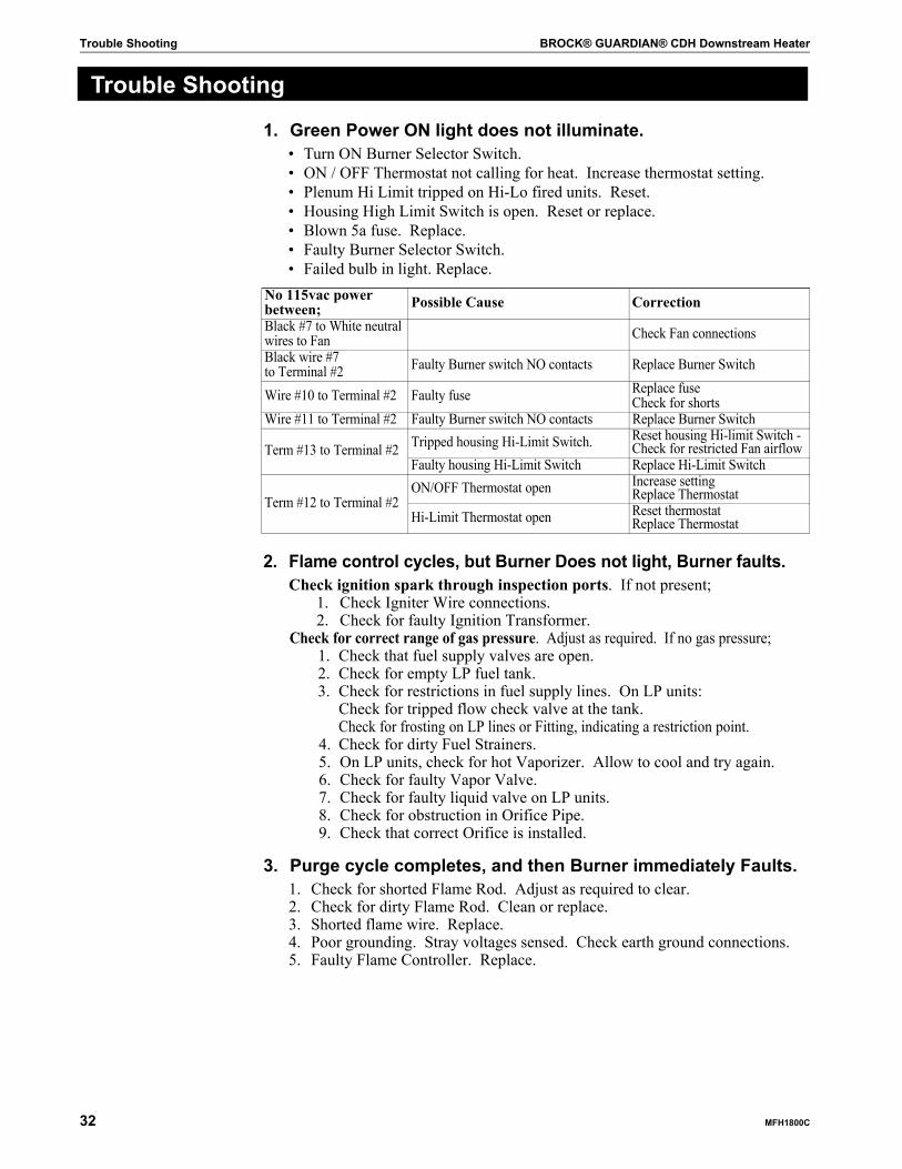
1. Green Power ON light does not illuminate.• Turn ON Burner Selector Switch.• ON / OFF Thermostat not calling for heat. Increase thermostat setting.• Plenum Hi Limit tripped on Hi-Lo fired units. Reset.• Housing High Limit Switch is open. Reset or replace.• Blown 5a fuse. Replace.• Faulty Burner Selector Switch.• Failed bulb in light. Replace.
2. Flame control cycles, but Burner Does not light, Burner faults.Check ignition spark through inspection ports. If not present;
1. Check Igniter Wire connections.2. Check for faulty Ignition Transformer.
Check for correct range of gas pressure. Adjust as required. If no gas pressure;1. Check that fuel supply valves are open.2. Check for empty LP fuel tank.3. Check for restrictions in fuel supply lines. On LP units:
Check for tripped flow check valve at the tank.Check for frosting on LP lines or Fitting, indicating a restriction point.
4. Check for dirty Fuel Strainers.5. On LP units, check for hot Vaporizer. Allow to cool and try again.6. Check for faulty Vapor Valve.7. Check for faulty liquid valve on LP units.8. Check for obstruction in Orifice Pipe.9. Check that correct Orifice is installed.
3. Purge cycle completes, and then Burner immediately Faults. 1. Check for shorted Flame Rod. Adjust as required to clear.2. Check for dirty Flame Rod. Clean or replace.3. Shorted flame wire. Replace.4. Poor grounding. Stray voltages sensed. Check earth ground connections.5. Faulty Flame Controller. Replace.
Trouble Shooting
No 115vac power between; Possible Cause CorrectionBlack #7 to White neutral wires to Fan Check Fan connectionsBlack wire #7 to Terminal #2 Faulty Burner switch NO contacts Replace Burner Switch
Wire #10 to Terminal #2 Faulty fuse Replace fuseCheck for shorts
Wire #11 to Terminal #2 Faulty Burner switch NO contacts Replace Burner Switch
Term #13 to Terminal #2 Tripped housing Hi-Limit Switch. Reset housing Hi-limit Switch -Check for restricted Fan airflow
Faulty housing Hi-Limit Switch Replace Hi-Limit Switch
Term #12 to Terminal #2ON/OFF Thermostat open Increase setting
Replace ThermostatHi-Limit Thermostat open Reset thermostat
Replace Thermostat

BROCK® GUARDIAN® CDH Downstream Heater Trouble Shooting
MFH1800C 33
4. Burner lights, runs 10 (ten) seconds, and then Faults.1. Burner pressure too low / high to sense fire.
Adjust pressure to appropriate range.2. Flame wire not connected. Reconnect.3. Ground to Burner is poor.
Check for ground screw connection on Burner Control base.Check for loose ground connections on Burner green ground wire.Poor flame quality. See below.Poor Flame Rod positioning. See illustrations showing proper position.
5. Flame Control runs continuously in the Purge cycle (solid yellow light).Check the wire connection to Terminal #6.
6. Green Power On Light illuminated, but Flame Control does not run1. Be sure the Flame Control is fully snapped into the base.2. Check for good wire connections on Terminal 12 and 2 of the base.3. Replace the Flame Control.
7. Burner blows a fuse:1. Immediately when the Burner Switch is turned ON
• Shorted housing High Limit Switch• Shorted ON/OFF or Plenum Hi-Limit Thermostat or Thermostat wires.• Shorted Flame Board
2. Immediately following the 25-second Purge cycle• Shorted Ignition Transformer• Shorted Gas Valve Coil• Shorted Vapor Hi-Limit on LP unit.
3. Immediately following the 15-second trial for ignition cycle (35 seconds after turning on)
• Shorted Hi/Lo Thermostat or Thermostat wires• Shorted Hi/Lo Valve Coil
8. Extremely yellow or sooty flame1. Gas pressure is too high.
• Reduce gas pressure to an appropriate range.• Check that the Vent is open on the Fuel Pressure Gauge.• Check for correct orifice sizing.
2. Too low an airflow velocity.• High static pressure on the Fan is causing the Fan to stall.
Reduce gas pressure.Reduce grain depth in the in.The Fan is too large for bin size and depth. Grain crusted over. Core the bin.The Drying Floor is plugged.
• Insufficient airflow performance from the Fan.3. Restricted airflow in Burner Venturi Casting or Diffuser. Remove the Burner
Cup and check for obstructions.4. Connected to a Fan without air straightening vanes. Install air straightening
vanes or replace the Fan.5. Incorrect Diffuser sizing. Check fuel specifications. See Fuel Specifications
Chart on Pages 29-30.
Parts List BROCK® GUARDIAN® CDH Downstream Heater
34 MFH1800C
Housing
Parts List
CDH Housing Package CDH27-10-HP
CDH27-15-HP
CDH27-20-HP
CDH30-HP
CDH33-40-HP
CDH33-50-HP
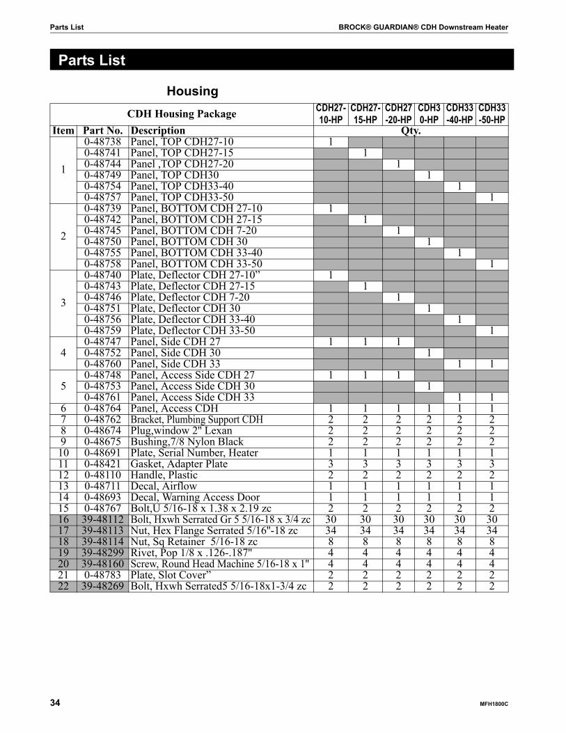
Item Part No. Description Qty.
1
0-48738 Panel, TOP CDH27-10 10-48741 Panel, TOP CDH27-15 10-48744 Panel ,TOP CDH27-20 10-48749 Panel, TOP CDH30 10-48754 Panel, TOP CDH33-40 10-48757 Panel, TOP CDH33-50 1
2
0-48739 Panel, BOTTOM CDH 27-10 10-48742 Panel, BOTTOM CDH 27-15 10-48745 Panel, BOTTOM CDH 7-20 10-48750 Panel, BOTTOM CDH 30 10-48755 Panel, BOTTOM CDH 33-40 10-48758 Panel, BOTTOM CDH 33-50 1
3
0-48740 Plate, Deflector CDH 27-10” 10-48743 Plate, Deflector CDH 27-15 10-48746 Plate, Deflector CDH 7-20 10-48751 Plate, Deflector CDH 30 10-48756 Plate, Deflector CDH 33-40 10-48759 Plate, Deflector CDH 33-50 1
40-48747 Panel, Side CDH 27 1 1 10-48752 Panel, Side CDH 30 10-48760 Panel, Side CDH 33 1 1
50-48748 Panel, Access Side CDH 27 1 1 10-48753 Panel, Access Side CDH 30 10-48761 Panel, Access Side CDH 33 1 1
6 0-48764 Panel, Access CDH 1 1 1 1 1 17 0-48762 Bracket, Plumbing Support CDH 2 2 2 2 2 28 0-48674 Plug,window 2'' Lexan 2 2 2 2 2 29 0-48675 Bushing,7/8 Nylon Black 2 2 2 2 2 210 0-48691 Plate, Serial Number, Heater 1 1 1 1 1 111 0-48421 Gasket, Adapter Plate 3 3 3 3 3 312 0-48110 Handle, Plastic 2 2 2 2 2 213 0-48711 Decal, Airflow 1 1 1 1 1 114 0-48693 Decal, Warning Access Door 1 1 1 1 1 115 0-48767 Bolt,U 5/16-18 x 1.38 x 2.19 zc 2 2 2 2 2 216 39-48112 Bolt, Hxwh Serrated Gr 5 5/16-18 x 3/4 zc 30 30 30 30 30 3017 39-48113 Nut, Hex Flange Serrated 5/16''-18 zc 34 34 34 34 34 3418 39-48114 Nut, Sq Retainer 5/16-18 zc 8 8 8 8 8 819 39-48299 Rivet, Pop 1/8 x .126-.187'' 4 4 4 4 4 420 39-48160 Screw, Round Head Machine 5/16-18 x 1'' 4 4 4 4 4 421 0-48783 Plate, Slot Cover” 2 2 2 2 2 222 39-48269 Bolt, Hxwh Serrated5 5/16-18x1-3/4 zc 2 2 2 2 2 2

BROCK® GUARDIAN® CDH Downstream Heater Parts List
MFH1800C 35
Figure 22.
Figure 23. Housing
Housing Assembly
Parts List BROCK® GUARDIAN® CDH Downstream Heater
36 MFH1800C
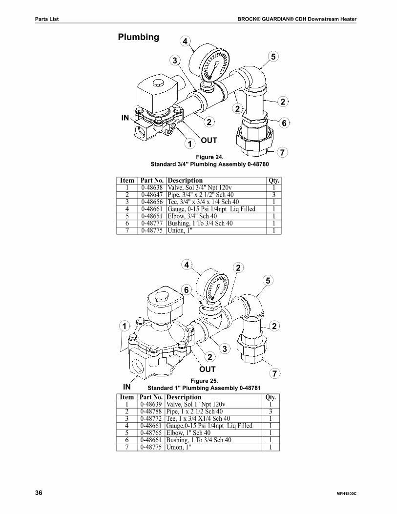
Item Part No. Description Qty.1 0-48638 Valve, Sol 3/4'' Npt 120v 12 0-48647 Pipe, 3/4'' x 2 1/2'' Sch 40 33 0-48656 Tee, 3/4'' x 3/4 x 1/4 Sch 40 14 0-48661 Gauge, 0-15 Psi 1/4npt Liq Filled 15 0-48651 Elbow, 3/4'' Sch 40 16 0-48777 Bushing, 1 To 3/4 Sch 40 17 0-48775 Union, 1'' 1
Figure 24. Standard 3/4'' Plumbing Assembly 0-48780
1
2
5
4
3
26
7
2
Plumbing
IN
OUT
Item Part No. Description Qty.1 0-48639 Valve, Sol 1'' Npt 120v 12 0-48788 Pipe, 1 x 2 1/2 Sch 40 33 0-48772 Tee, 1 x 3/4 X1/4 Sch 40 14 0-48661 Gauge,0-15 Psi 1/4npt Liq Filled 15 0-48765 Elbow, 1'' Sch 40 16 0-48661 Bushing, 1 To 3/4 Sch 40 17 0-48775 Union, 1'' 1
Figure 25. Standard 1'' Plumbing Assembly 0-48781
7
23
25
4
2
6
1
IN
OUT

BROCK® GUARDIAN® CDH Downstream Heater Parts List
MFH1800C 37
Item Part No. Description Qty.1 0-48636 Valve, Sol 1/4 Npt 120v (Liquid) 12 0-48658 Nipple, 1/4 X 1 1/2 Sch 80 13 0-48654 Bushing, 1/2 To 1/4 Sch 80 14 0-48655 Tee, 1/2 X 1/2 X 1/4 Sch 80 15 0-48648 Pipe, 1/2 X 2 Sch 80 16 0-48652 Elbow, 1/2 Sch 80 17 0-48643 Valve, Relief 1/4 Npt 300 psi 1
Item Part No. Description Qty.1 0-48642 Regulator, 1/2 npt 30 psi 12 0-48648 Pipe, 1/2 x 2 Sch 80 13 0-48657 Tee, 1/2 x 1/2 x 1/2 Sch 080 14 0-48680 Thermostat, Hi-Limit 210F 1/2 npt x 1.2 npt 15 0-48682 Coupling, 1/2 Sch 40 1
Figure 26. Intake Plumbing Assembly 0-48709
4
7
2 3
1
5
6
OUT
IN
1
54
32
Figure 27. Regulator Assembly 0-48789
Parts List BROCK® GUARDIAN® CDH Downstream Heater
38 MFH1800C
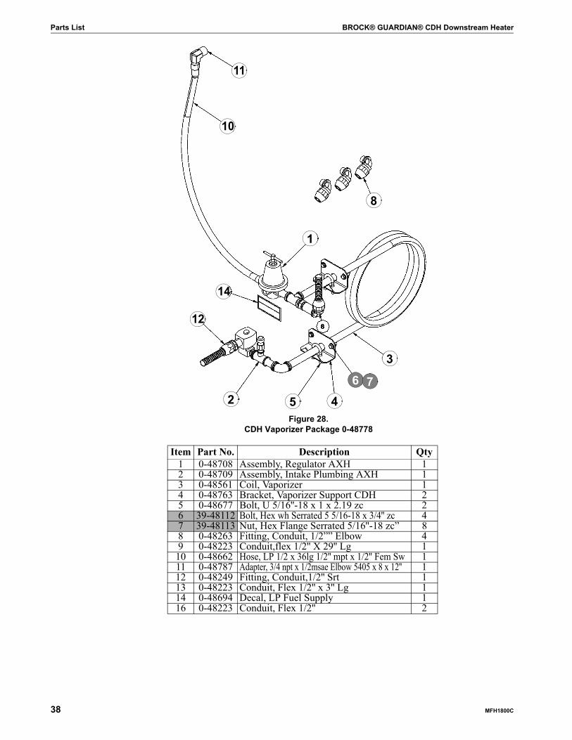
Item Part No. Description Qty1 0-48708 Assembly, Regulator AXH 12 0-48709 Assembly, Intake Plumbing AXH 13 0-48561 Coil, Vaporizer 14 0-48763 Bracket, Vaporizer Support CDH 25 0-48677 Bolt, U 5/16''-18 x 1 x 2.19 zc 26 39-48112 Bolt, Hex wh Serrated 5 5/16-18 x 3/4'' zc 47 39-48113 Nut, Hex Flange Serrated 5/16''-18 zc” 88 0-48263 Fitting, Conduit, 1/2”” Elbow 49 0-48223 Conduit,flex 1/2'' X 29'' Lg 1
10 0-48662 Hose, LP 1/2 x 36lg 1/2'' mpt x 1/2'' Fem Sw 111 0-48787 Adapter, 3/4 npt x 1/2msae Elbow 5405 x 8 x 12'' 112 0-48249 Fitting, Conduit,1/2'' Srt 113 0-48223 Conduit, Flex 1/2'' x 3'' Lg 114 0-48694 Decal, LP Fuel Supply 116 0-48223 Conduit, Flex 1/2'' 2
Figure 28. CDH Vaporizer Package 0-48778
1
8
11
10
14
45
6 7
3
2
12
BROCK® GUARDIAN® CDH Downstream Heater Parts List
MFH1800C 39
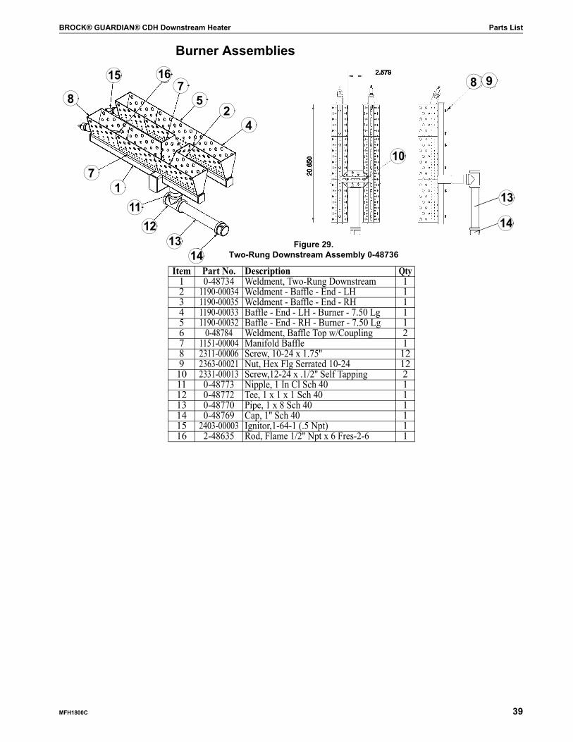
Item Part No. Description Qty1 0-48734 Weldment, Two-Rung Downstream 12 1190-00034 Weldment - Baffle - End - LH 13 1190-00035 Weldment - Baffle - End - RH 14 1190-00033 Baffle - End - LH - Burner - 7.50 Lg 15 1190-00032 Baffle - End - RH - Burner - 7.50 Lg 16 0-48784 Weldment, Baffle Top w/Coupling 27 1151-00004 Manifold Baffle 18 2311-00006 Screw, 10-24 x 1.75'' 129 2363-00021 Nut, Hex Flg Serrated 10-24 12
10 2331-00013 Screw,12-24 x .1/2'' Self Tapping 211 0-48773 Nipple, 1 In Cl Sch 40 112 0-48772 Tee, 1 x 1 x 1 Sch 40 113 0-48770 Pipe, 1 x 8 Sch 40 114 0-48769 Cap, 1'' Sch 40 115 2403-00003 Ignitor,1-64-1 (.5 Npt) 116 2-48635 Rod, Flame 1/2'' Npt x 6 Fres-2-6 1
13
1615
17
8
12
52
4
14
13
14
Figure 29. Two-Rung Downstream Assembly 0-48736
13
Burner Assemblies
8 9
14
7
10
14
11

Parts List BROCK® GUARDIAN® CDH Downstream Heater
40 MFH1800C
Item Part No. Description Qty1 0-48735 Weldment, Three-Rung Downstream 12 1190-00034 Weldment - Baffle - End - LH 13 1190-00027 Weldment - Baffle - Short - End 14 1190-00035 Weldment - Baffle - End - RH 15 1190-00032 Baffle - End - RH - Burner - 7.50 Lg 16 1190-00026 Baffle - Short - End - Burner 17 1190-00033 Baffle - End - LH - Burner - 7.50 Lg 18 0-48784 Weldment, Baffle Top w/Coupling 29 0-48786 Weldment, Baffle Top” 1
10 1151-00004 Manifold Baffle 211 2311-00006 Screw,10-24 x 1.75'' 212 2311-00006 Screw,10-24 x 1.75'' 1613 2331-00013 Screw,12-24 x .5 Self Tapping 414 2363-00021 Nut, Hx Flg Serrated 10-24 1615 0-48773 Nipple, 1 In Cl Sch 40 116 0-48772 Tee, 1 x 1 x 1 Sch 40 117 0-48770 Pipe, 1 x 8 Sch 40” 118 0-48769 Cap, 1'' Sch 40 119 2403-00003 Ignitor,1-64-1 (.5 Npt) 120 2-48635 Rod, Flame 1/2 Npt X 6 Fres-2-6 1
3
Above: Figure 30. Three-Rung Downstream Assembly 0-48737
4
72
10
8
9 156
11 14
115
16
17
18
13
1920

BROCK® GUARDIAN® CDH Downstream Heater Parts List
MFH1800C 41
20
76
23
514 9 13 11 13 35 36
25
34
2224
25
Controls
Section A-A Detail
Figure 31. Control Assembly 0-48779
21
33
3834
Section A Detail
14
18
17
16
18
1929
1
2
398 10 12
Item Part No. Description Qty1 0-48094-3 Box, Elec Ax 12 0-48095 Lid, Elec Box 14x16 Blk 13 0-48627 Panel, Elec. Mounting, AXH 14 2502-00001 Xfmr, Ign 175va 120v-60000v
60h 15 0-48620 Base, Burner Control 16 0-48696 Control, Burner 115v Flame
Rect LME69 17 0-48698 Switch, Assy Selector 2nc, 1no 18 0-48664 Nameplate, OFF/ON 19 0-48667 Operator, Pilot Light Green 110 0-48665 Nameplate, Power ON 111 0-48668 Operator, Pilot Light Red 112 0-48666 Nameplate, FAULT 113 0-48669 Lamp, Led 120 V White 214 0-48233 Terminal, Fuse 15a 1/4 x 1 1/4'' 115 0-48236 Fuse,5a 250v 1/4 x 1-1/4'' 116 0-48234 Terminial, 20a 26-12ga 817 0-48235 Barrier, End Terminial 118 0-48237 Clamp, End 35mm 219 0-48704 Track, 35mm x 3.88'' 120 0-48328 Lug, Ground 6-14ga 221 0-48272 Plug, Liquid Tight Knock-seal 7/8'' 122 0-48675 Bushing, Snap Heyco 1/2'' 223 0-48679 Thermostat, Hi Limit 200f Man
Reset 124 0-48223 Conduit, Flex 1/2'' 80''25 0-48263 Fitting, Conduit, 1/2'' Elbow 226 0-48357 Wire 10 Ga Green Thhn 100''27 0-48361 Wire 16ga Black Thw 100''28 0-48360 Wire 16ga White Thw 100''29 0-48670 Label,white Unprinted (10) 5 mm 230 0-48692 Decal, Diagram Heater 131 0-48354 Decal, Electrical Hazard 132 0-48187 Decal, BROCK® 12'' 133 39-48300 Screw, Pan #8-32 x 1/2'' 834 39-48301 Screw, Pan 10-32 x 3/8'' 1335 30862 Latch, Box (Grey) 236 30863 Pivot, Latch (Grey) 237 34767 Seal, Neop Closed Cell .125'' 5 ft38 6723 Wshr, .203 x .625 x .044 c/z 439 0-48502 Gasket, 1/4 x 1/2 x 35ft Pvc Foam 63''40 0-48360 Wire 16ga White Thw 60''41 0-48359 Wire 16ga Red Thw 60''
Parts List BROCK® GUARDIAN® CDH Downstream Heater
42 MFH1800C
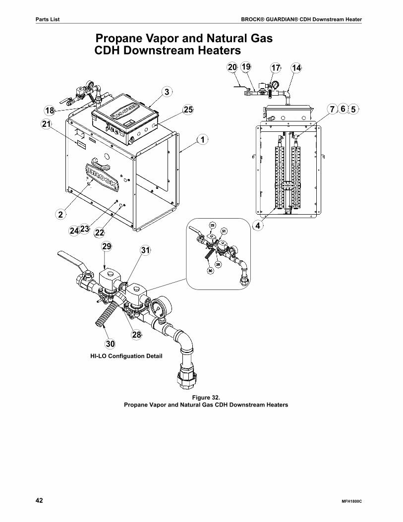
Propane Vapor and Natural Gas CDH Downstream Heaters
Figure 32. Propane Vapor and Natural Gas CDH Downstream Heaters
7
20
25 5
29
3
1
18
2
141719
6
31
HI-LO Configuation Detail
2830
4
21
222324

BROCK® GUARDIAN® CDH Downstream Heater Parts List
MFH1800C 43
Propane Vapor and Natural Gas CDH Downstream HeatersItem Part No. Description Qty.
1
CDH27-10-HP Pkg, Heater Housing CDH27-10 1 1CDH27-15-HP Pkg, Heater Housing CDH27-15 1 1CDH27-20-HP Pkg, Heater Housing CDH27-20 1 1
CDH30-HP Pkg, Heater Housing CDH30 1 1CDH33-40-HP Pkg, Heater Housing CDH33-40 1 1CDH33-50-HP Pkg, Heater Housing CDH33-50 1 1
2 0-48188 Decal, BROCK® 16'' 2 2 2 2 2 2 2 2 2 2 2 23 0-48779 Assembly, Control Box CDH 1 1 1 1 1 1 1 1 1 1 1 14 0-48736 Assembly, Burner Two-rung Downstream 1 1 1 1 1 1
0-48737 Assembly, Burner Three-rung Downstream 1 1 1 1 1 15 0-48671 Conduit, 3/8'' Flex Alum 1.6' 1.6' 1.6' 1.6' 1.6' 1.6' 1.6' 1.6' 1.6' 1.6' 1.6' 1.6'
0-48671 Conduit, 3/8'' Flex Alum 1.6' 1.6' 1.6' 1.6' 1.6' 1.6' 1.6' 1.6' 1.6' 1.6' 1.6' 1.6'6 0-48672 Fitting, Str 3/8'' Flex Alum Conduit 4 4 4 4 4 4 4 4 4 4 4 47 2403-00013 Cap, Spark Plug 2 2 2 2 2 2 2 2 2 2 2 28 0-48361 Wire 16ga Black Thw 25'' 25'' 25'' 25'' 25'' 25'' 25'' 25'' 25'' 25'' 25'' 25''9 2518-00001 Wire, Ignition 2' 2' 2' 2' 2' 2' 2' 2' 2' 2' 2' 2'10 0-48366 Terminal, Fork #8 18-14ga Insul 1 1 1 1 1 1 1 1 1 1 1 111 0-48357 Wire 10 Ga Green Thhn 13'' 13'' 13'' 13'' 13'' 13'' 13'' 13'' 13'' 13'' 13'' 13''12 0-48368 Terminal, Ring 5/16 #10-12ga 2 2 2 2 2 2 2 2 2 2 2 213 0-48342 Tie, Wire 2 2 2 2 2 2 2 2 2 2 2 214 0-48780 Assembly, Standard Plumbing CDH 3/4'' 1 1 1 1 1 1
0-48781 Assembly, Standard Plumbing CDH 1'' 1 1 1 1 1 1
15
0-48776-141 Orifice,.141 x3/4 npt Brass 1 10-48776-172 Orifice, .172 x 3/4 npt Brass 1 1 1 1 1 10-48776-203 Orifice, .203 x 3/4 npt Brass 1 1 1 1 1 10-48776-219 Orifice, .219 x 3/4 npt Brass 1 10-48776-250 Orifice, .250 x 3/4 npt Brass 1 1 1 1 1 10-48776-281 Orifice, .281 x 3/4 npt Brass 1 1 1 1 1 10-48776-313 Orifice, .313 x 3/4 npt Brass 1 1 1 1 1 10-48776-344 Orifice, .344 x 3/4 npt Brass 1 10-48776-359 Orifice, .359 x 3/4 npt Brass 1 1 1 10-48776-375 Orifice, .375 x 3/4 npt Brass 1 10-48776-406 Orifice, .406 x 3/4 npt Brass 1 10-48776-438 Orifice, .438 x 3/4 npt Brass 1 10-48776-469 Orifice, .469 x 3/4 npt Brass 1 1
16 0-48223 Conduit, Flex 1/2'' 33'' 33'' 33'' 33'' 33'' 33'' 33'' 33'' 33'' 33'' 33'' 33''17 0-48263 Fitting, Conduit, 1/2'' Elbow 2 2 2 2 2 2 2 2 2 2 2 218 0-48771 Pipe, 1 x 24 Sch 80 3/4'' npt Tap One End 1 1 1 1 1 1 1 1
0-48785 Pipe, 1 x 30 Sch 80 3/4 HI/LO Tap One End 1 1 1 119 0-48647 Pipe, 3/4 x 2 1/2'' Sch 40 1 1 1 1 1 1
0-48788 Nipple, 1 x 2 1/2 Sch 40 1 1 1 1 1 120 0-48684 Valve, Ball 3/4 '' Cga 1 1 1 1 1 1
0-48746 Valve, Ball 1''Cga 1 1 1 1 1 121 0-48695 Decal, PV/N Fuel Supply 1 1 1 1 1 1 1 1 1 1 1 122 0-48690 Plug, 1 1/8'' Nylon Black 2 2 2 2 2 2 2 2 2 2 2 223 39-48112 Bolt, HXWH Serrated 5/16-18 x 3/4'' zc Gr.5 4 4 4 4 4 4 4 4 4 4 4 424 39-48113 Nut, Hex Flange Serrated 5/16-18 zc” 4 4 4 4 4 4 4 4 4 4 4 425 0-48272 Plug, Liquid Tight Knock-seal 7/8'' 3 2 3 2 3 2 3 2 3 2 3 2
HI-LO Fire
28 0-48647 Pipe, 3/4 x 2 1/2'' Sch 40 1 1 10-48788 Nipple, 1 x 2 1/2'' Sch 40 1 1 1
29 0-48640 Valve, Sol HI/LO 3/4 npt 120v 1 1 10-48641 Valve, Sol HI/LO 1 npt 120v 1 1 1
30 0-48223 Conduit, Flex 1/2'' 33'' 33'' 33'' 33'' 33'' 33''31 0-48263 Fitting, Conduit, 1/2''Elbow 2 2 2 2 2 2
32 0-48324 Carton, AX24 / AX26 / AX28 1 1 1 1 1 1 1 1 1 1 1 133 0-48325 Lid, Ax24 / Ax26 / AX28 1 1 1 1 1 1 1 1 1 1 1 134 0-48427 Skid, AX24 / AX26 / AX28 1 1 1 1 1 1 1 135 0-48586 Skid, Centrifugal Fans 1 1 1 1
CDH2
-10-
N/7P
V
CDH2
7-10-N
/PV-HL
CDH2
7-15
-N/P
V
CDH2
7-15-N
/PV-HL
CDH2
7-20
-N/P
V
CDH2
7-20-N
/PV-HL
CDH3
0-N/
PV
CDH3
0-N/
PV-H
L
CDH3
3-40
-N/P
V
CDH3
3-40-N
/PV-HL
CDH3
3-50
-N/P
V
CDH3
3-50
-N/P
V-
Parts List BROCK® GUARDIAN® CDH Downstream Heater
44 MFH1800C
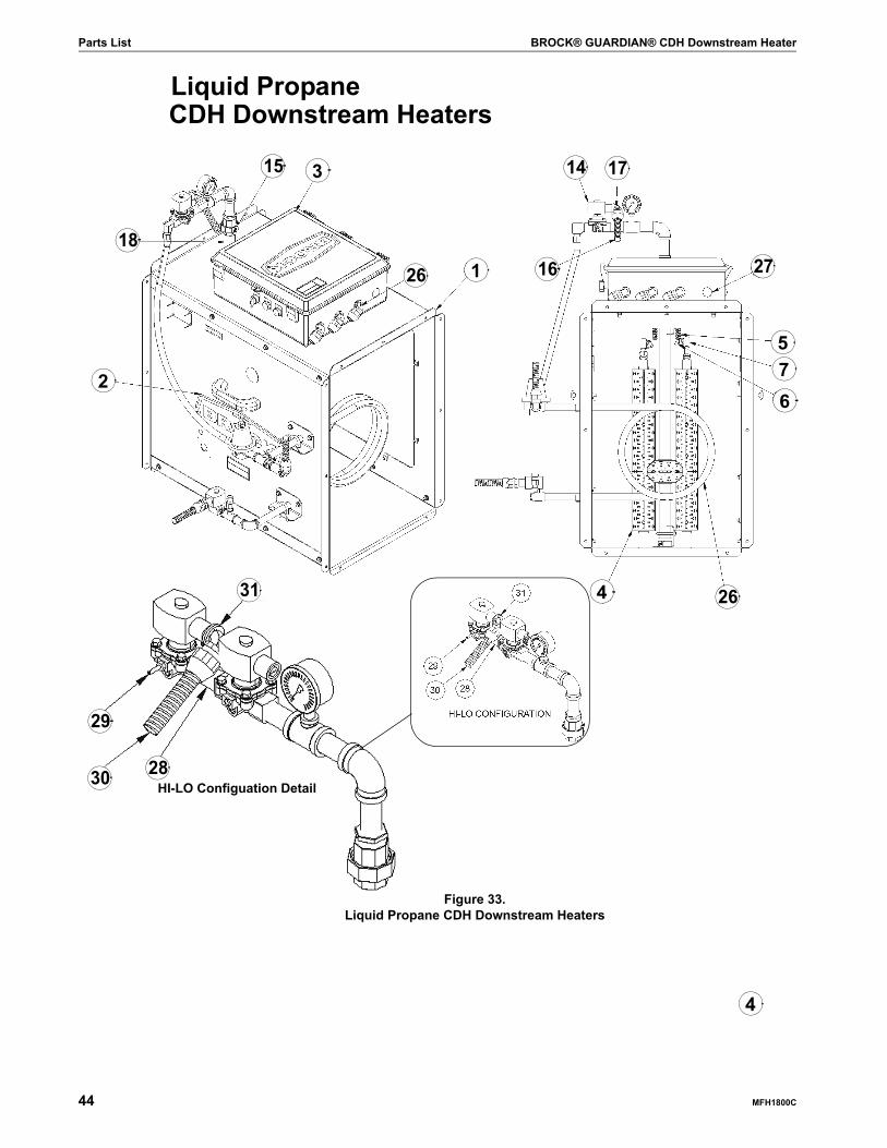
CDH Downstream Heaters
Figure 33. Liquid Propane CDH Downstream Heaters
Liquid Propane
7
1626
5
29
3
1
15
18
2
14 17
27
6
4 2631
HI-LO Configuation Detail2830
4
BROCK® GUARDIAN® CDH Downstream Heater Parts List
MFH1800C 45
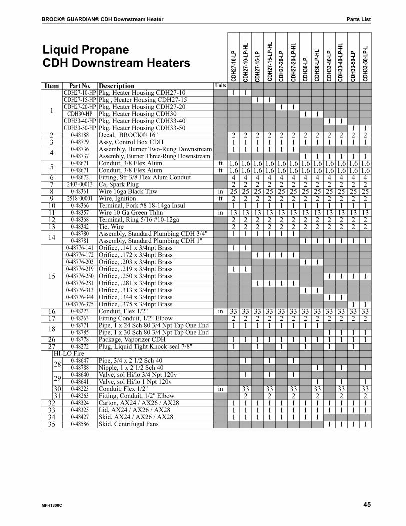
Liquid Propane CDH Downstream Heaters
Item Part No. Description Units
1
CDH27-10-HP Pkg, Heater Housing CDH27-10 1 1CDH27-15-HP Pkg , Heater Housing CDH27-15 1 1CDH27-20-HP Pkg, Heater Housing CDH27-20 1 1
CDH30-HP Pkg, Heater Housing CDH30 1 1CDH33-40-HP Pkg, Heater Housing CDH33-40 1 1CDH33-50-HP Pkg, Heater Housing CDH33-50 1 1
2 0-48188 Decal, BROCK® 16'' 2 2 2 2 2 2 2 2 2 2 2 23 0-48779 Assy, Control Box CDH 1 1 1 1 1 1 1 1 1 1 1 14 0-48736 Assembly, Burner Two-Rung Downstream 1 1 1 1 1 1
0-48737 Assembly, Burner Three-Rung Downstream 1 1 1 1 1 15 0-48671 Conduit, 3/8 Flex Alum ft 1.6 1.6 1.6 1.6 1.6 1.6 1.6 1.6 1.6 1.6 1.6 1.6
0-48671 Conduit, 3/8 Flex Alum ft 1.6 1.6 1.6 1.6 1.6 1.6 1.6 1.6 1.6 1.6 1.6 1.66 0-48672 Fitting, Str 3/8 Flex Alum Conduit 4 4 4 4 4 4 4 4 4 4 4 47 2403-00013 Ca, Spark Plug 2 2 2 2 2 2 2 2 2 2 2 28 0-48361 Wire 16ga Black Thw in 25 25 25 25 25 25 25 25 25 25 25 259 2518-00001 Wire, Ignition ft 2 2 2 2 2 2 2 2 2 2 2 2
10 0-48366 Terminal, Fork #8 18-14ga Insul 1 1 1 1 1 1 1 1 1 1 1 111 0-48357 Wire 10 Ga Green Thhn in 13 13 13 13 13 13 13 13 13 13 13 1312 0-48368 Terminal, Ring 5/16 #10-12ga 2 2 2 2 2 2 2 2 2 2 2 213 0-48342 Tie, Wire 2 2 2 2 2 2 2 2 2 2 2 214 0-48780 Assembly, Standard Plumbing CDH 3/4'' 1 1 1 1 1 1
0-48781 Assembly, Standard Plumbing CDH 1'' 1 1 1 1 1 1
15
0-48776-141 Orifice, .141 x 3/4npt Brass 1 10-48776-172 Orifice, .172 x 3/4npt Brass 1 1 1 10-48776-203 Orifice, .203 x 3/4npt Brass 1 10-48776-219 Orifice, .219 x 3/4npt Brass 1 10-48776-250 Orifice, .250 x 3/4npt Brass 1 1 1 10-48776-281 Orifice, .281 x 3/4npt Brass 1 1 1 10-48776-313 Orifice, .313 x 3/4npt Brass 1 10-48776-344 Orifice, .344 x 3/4npt Brass 1 10-48776-375 Orifice, .375 x 3/4npt Brass 1 1
16 0-48223 Conduit, Flex 1/2'' in 33 33 33 33 33 33 33 33 33 33 33 3317 0-48263 Fitting Conduit, 1/2'' Elbow 2 2 2 2 2 2 2 2 2 2 2 218 0-48771 Pipe, 1 x 24 Sch 80 3/4 Npt Tap One End 1 1 1 1 1 1 1 1
0-48785 Pipe, 1 x 30 Sch 80 3/4 Npt Tap One End 1 1 1 126 0-48778 Package, Vaporizer CDH 1 1 1 1 1 1 1 1 1 1 1 127 0-48272 Plug, Liquid Tight Knock-seal 7/8'' 1 1 1 1 1 1
HI-LO Fire
28 0-48647 Pipe, 3/4 x 2 1/2 Sch 40 1 1 10-48788 Nipple, 1 x 2 1/2 Sch 40 1 1 1
29 0-48640 Valve, sol Hi/lo 3/4 Npt 120v 1 1 10-48641 Valve, sol Hi/lo 1 Npt 120v 1 1 1
30 0-48223 Conduit, Flex 1/2'' in 33 33 33 33 33 3331 0-48263 Fitting, Conduit, 1/2'' Elbow 2 2 2 2 2 2
32 0-48324 Carton, AX24 / AX26 / AX28 1 1 1 1 1 1 1 1 1 1 1 133 0-48325 Lid, AX24 / AX26 / AX28 1 1 1 1 1 1 1 1 1 1 1 134 0-48427 Skid, AX24 / AX26 / AX28 1 1 1 1 1 1 1 135 0-48586 Skid, Centrifugal Fans 1 1 1 1
CDH2
7-10
-LP
CDH2
7-10
-LP-
HL
CDH2
7-15
-LP
CDH2
7-15
-LP-
HL
CDH2
7-20
-LP
CDH2
7-20
-LP-
HL
CDH3
0-LP
CDH3
0-LP
-HL
CDH3
3-40
-LP
CDH3
3-40
-LP-
HL
CDH3
3-50
-LP
CDH3
3-50
-LP-
L

Models and Specifications BROCK® GUARDIAN® CDH Downstream Heater
46 MFH1800C
Heater DimensionsSee Page 16 in this Manual.
Models and Specifications
*Thermostat Control is required to operate all Heaters.HT-200 Heater Theromostat Control for all Heater operationsHLT-250 Hi-Limit Thermostat Control (To be used with Hi-Lo and Modulating Valve Heaters)HMV-3/4 Moldulating Valves (can be added in the field or factory-installed) (Add to the list price)Liquid Propane Heater comes standard with an Internal Vaporizer.Regulators are not included with Natural Gas or Propane Vapor Heaters.Heaters are designed for a 115-volt connection. If the Fan does not have 115-volt controls, a Step-down Transformer may be required.BROCK® Fans are equipped with a 100va Control Transformer. 460v and 575v BROCK® Fans: the Transformer must be changed to a 250va.

BROCK® GUARDIAN® CDH Downstream Heater Models and Specifications
MFH1800C 47

Different by Design™
BROCK GRAIN SYSTEMSA Division of CTB Inc.
Grain Conditioning Division1750 W. State Road 28 • Frankfort IN 46041Phone (765) 654-8517 • Fax (765) 654-8510
Toll Free (800) 541-7900e-mail: [email protected] • Internet: www.graindryers.com
andP.O. Box 2000 • Milford, Indiana 46542-2000 • U.S.A.
Phone (574) 658-4191 • Fax (574) 658-4133e-mail: [email protected] • Internet: http//www.brockmfg.com
and7400 East Thirteenth Street • Kansas City, Missouri 64126 • U.S.A.
Phone (816) 968-6101 Fax (816) 968-6272 TLX: 6841105
Printed in the U.S.A.
All specifications subject to change without notice.
Changes this issue:Most changes are a result of the new Burner Board 0-48696 LME69.
Changes last issue: updated to Owner/Operator’s Manual.
MFH1800COctober 2007