gsm network structure and network...
TRANSCRIPT
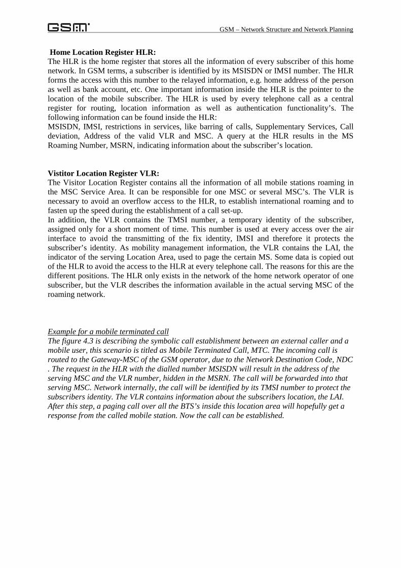
GSM – Network Structure and Network Planning
GSM Network Structure and Network Planning
Dipl.- Ing. Reiner Stuhlfauth, ROHDE & SCHWARZ; Training Centre
Contents:
1. Geographical structures in a GSM network
2. Methods of network planning
2.1. Principles of cellular networks
2.2. Cluster method
2.2.1. Cluster with sectorised cells
2.3. Analytical method
3. Radio cells
3.1. Antennas for mobile communication networks
3.2. Classes of radio cells
3.3. Radio cells optimisation and configuration
3.4. Capacity of the network
4. GSM – Network structure
4.1. Mobile Station, MS
4.2. Base Station Subsystem, BSS
4.3. Switching and Management Subsystem, SMSS
4.4. Operation and Maintenance Subsystem, OMSS
GSM – Network Structure and Network Planning
1. Geographical structures in a mobile communication network
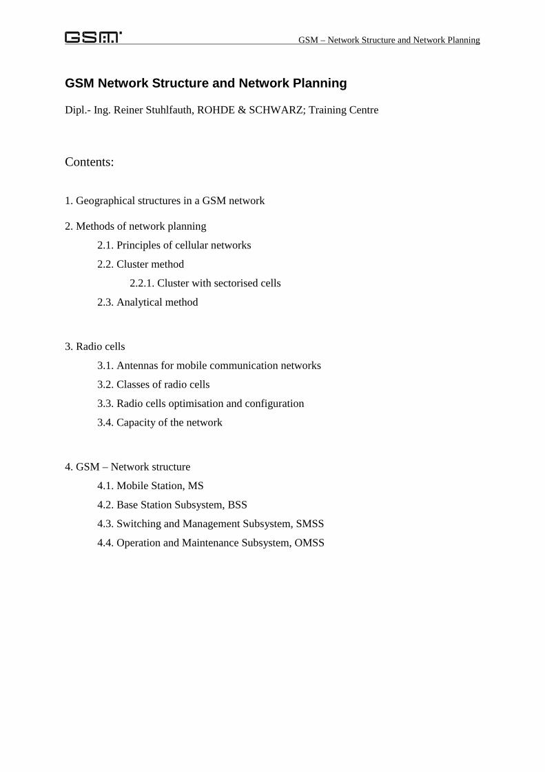
GSM is a world-wide standard for mobile communication with an extensive coverage. Due tothe mobility of the subscribers, the organisational structure must be subdivided into differentprocessing elements. The defined areas are necessary to establish point-to-point connections.
Figure: Geographical structures in GSM
GSM Service Area: This highest area describes the whole world of GSM; all realisednetwork elements are part of this area.
PLMN Service Area: The defined area of the Public Land Mobile Network is the servicearea of one network operator. The borders are not necessarily the political borders of onecountry, furthermore it is possible to define on-duty areas of different operators.
MSC Service Area: Depending on the offered network capacity, one operator is subdividinghis network into smaller service area, built up by one MSC. The MS is part of the switchingnetwork, responsible for connecting telephone calls. It possesses access to different databases, containing the information about the subscribers profile, location and securityfunctions. One MSC is the lowest switching level, it is forwarding the call into differentnetworks. Two mobile stations inside one MSC Service Area establishing one connection areconnected via the MSC, therefore it is forming the lowest switching level in the GSM world.
Location Area: Inside the GSM Area, the location area is the lowest existing level of thelocation information of one subscriber. The mobility management layer only knows in whichlocation area one subscriber is located. Each location area is identified by a so called LAI,Location Area Identity and belongs to exactly one MSC. A mobile station is allowed to roamwithin one location area without sending location information to the network. Only in case ofchanging the location area must the Mobile Station update the mobility managementinformation. This procedure is called location update.
Cell Area: The lowest area in the geographical layers is formed by one radio cell. The radiocell is stretched out by the radio coverage of one Base Transceiver Station, BTS and has arange between a few hundred metres up to a maximum of 35km. The Cell area forms theaccess point for the subscriber. After establishing a radio link to the BTS, the subscriber getsaccess to the whole backbone network of the mobile communication network. One radio cellis identified by its BSIC, the Base Station Identity Code. This code is broadcast in a periodic
GSM Service AreaPLMN Service AreaMSC Service AreaLocation AreaCell Area
GSM – Network Structure and Network Planning
manner to enable on the MS side a periodic survey of link strength and quality to both servingcell and neighbour cells.The whole network coverage is guaranteed by placing BTS’s over the network area andequipping them with the certain capacity to deal with the expected traffic. The followingpages describe strategies of network planning and optimisation.
2. Methods of radio network planning
2.1. Principle of cellular networks:
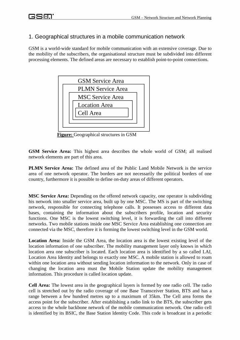
In comparison to a cable based telephone network, in a mobile communication network thetransfer of speech or data is performed by a radio link. This radio link will at least beestablished between the mobile station and the base station.The first existing radio networks were characterised by some features:Radio coverage, or serving cell area of about 60km radius.Radio link only within one serving cell, at the moment of leaving this serving cell, the callwas terminated.Switching-by-hand, no automatic routing of the call to the endpoint
A cellular network offers some further features to the user:Automatic mobility management and call routing: the network has a knowledge of subscriberslocation information that will be updated automatically.Calls are routed automatically to one subscriber, the mobile station is able to receive those so-called paging calls.The radio cells are overlapping, in case of transfer of one radio cell into another, the call willbe handed over. This procedure is then called handover.As a simplified model of cellular networks, the cell area is painted as a hexagonal structure.
Figure 2.1.1.: Conventionalnetwork, Radius < 60km
Figure 2.1.2.: Cellular network,Radius maximal 35km, typically 5– 8 km.
GSM – Network Structure and Network Planning
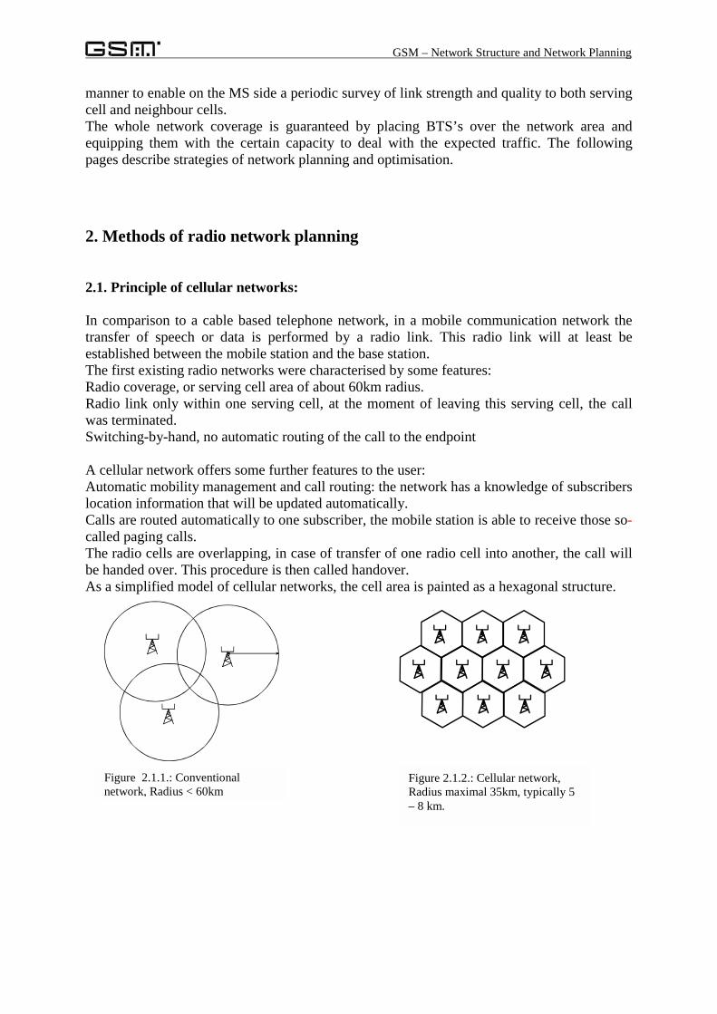
To establish the radio communication, every BTS gets a certain number of duplex frequencychannels assigned. This assignment offers a fix capacity to each cell. To enhance the capacity,the philosophy is not a small number of large radio cells with lots of frequency channels, it israther a big number of small radio cells with few frequency channels each. Every radio cellgets a certain number of duplex frequency channels assigned, depending on the expectedtraffic that must be conveyed.It is obvious, that the allowed frequency channels are assigned to multiple base stationsseveral times, getting into consequences, that every frequency channel is superimposed on thesame frequency channel, transmitted by another BTS. The network operators have to avoidinterference due to a skilful frequency planning to avoid common channel interference as wellas adjacent channel interference.
Figure: Origin of interference in a mobile communication network
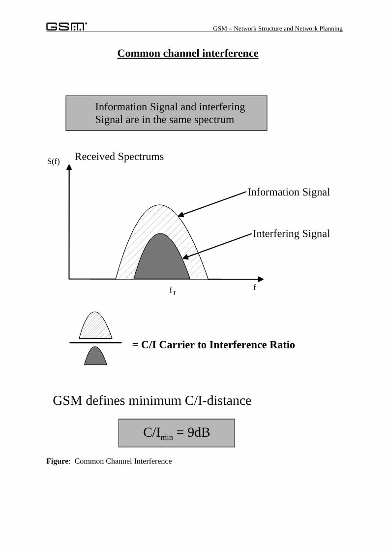
In GSM we calculate a tolerated minimum of Common Channel Interference level of C/Imin= 9dB.
Interference signals
Interferences in cellular Mobile Radio Systems
Informationsignal
Informationsignal
GSM – Network Structure and Network Planning
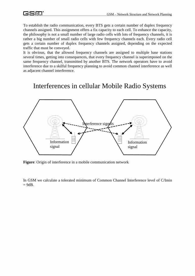
Figure: Common Channel Interference
fTf
S(f)
Common channel interference
= C/I Carrier to Interference Ratio
Received Spectrums
C/Imin = 9dB
GSM defines minimum C/I-distance
Information Signal and interfering Signal are in the same spectrum
Information Signal
Interfering Signal
GSM – Network Structure and Network Planning
2.2 Cluster method:
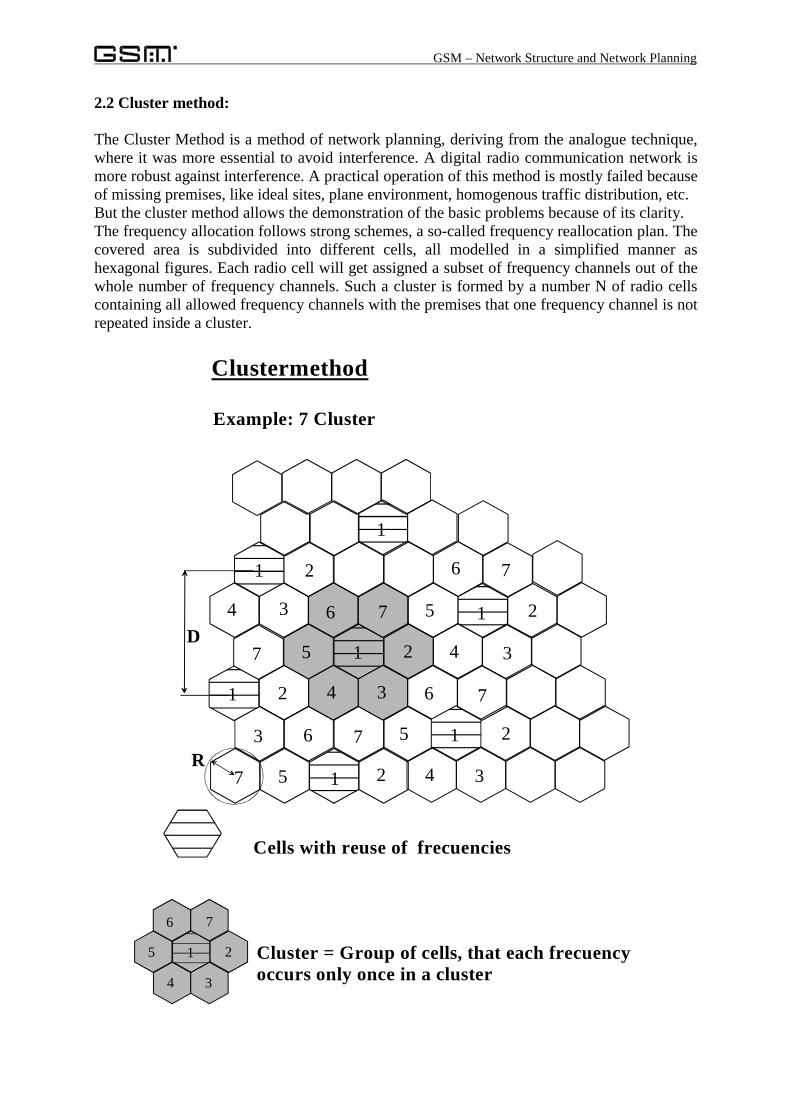
The Cluster Method is a method of network planning, deriving from the analogue technique,where it was more essential to avoid interference. A digital radio communication network ismore robust against interference. A practical operation of this method is mostly failed becauseof missing premises, like ideal sites, plane environment, homogenous traffic distribution, etc.But the cluster method allows the demonstration of the basic problems because of its clarity.The frequency allocation follows strong schemes, a so-called frequency reallocation plan. Thecovered area is subdivided into different cells, all modelled in a simplified manner ashexagonal figures. Each radio cell will get assigned a subset of frequency channels out of thewhole number of frequency channels. Such a cluster is formed by a number N of radio cellscontaining all allowed frequency channels with the premises that one frequency channel is notrepeated inside a cluster.
R
Clustermethod
Example: 7 Cluster
Cells with reuse of frecuencies
Cluster = Group of cells, that each frecuencyoccurs only once in a cluster
1 2
34
5
6 7
34
1 25
76
34
1 25
6 7
1
1
2
5 2
6 73
7
1
7
4 3
21
1 2
34
5
6 7
D
GSM – Network Structure and Network Planning
The important magnitude delimiting the cluster size is the Signal to Noise Ratio that can becalculated approximately:
( )24
3NRD
IC
=
≈
The table delivers some typical values for different cluster sizes:N C/I C/I in dB3 81 19,14 144 21,65 441 26,46 729 28,6
Apart from the cell radius, the network capacity is forming an essential parameter as well. Thesmaller the cluster, the more users can be supplied.
2.2.1. Cluster with sectorised cells
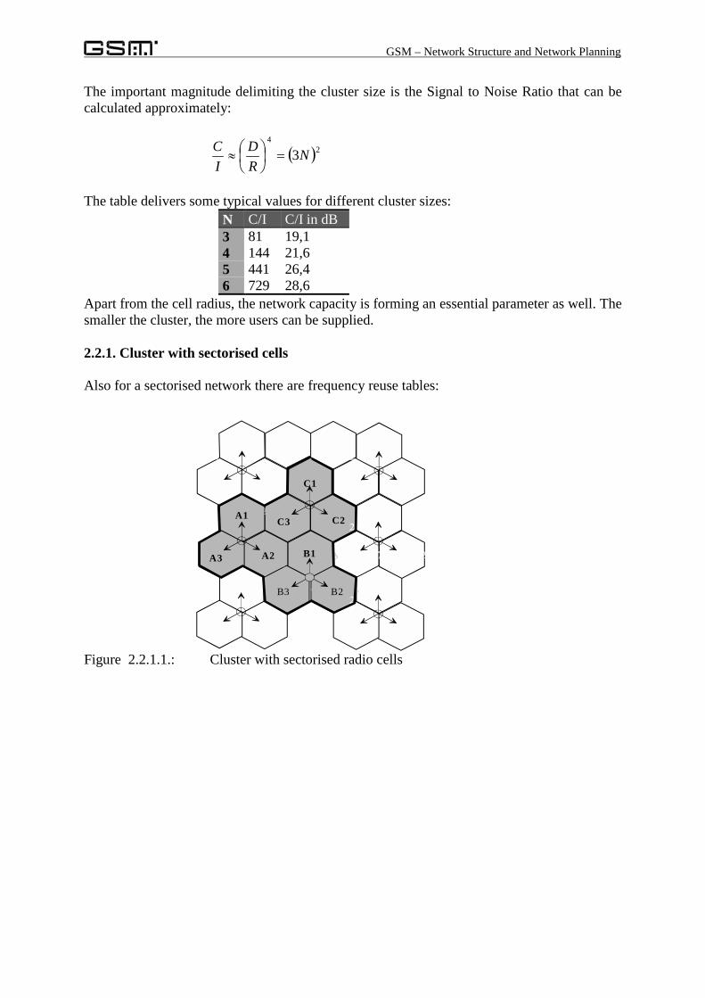
Also for a sectorised network there are frequency reuse tables:
Figure 2.2.1.1.: Cluster with sectorised radio cells
3
1
34
2 3
12
2A2A3 B1
B2
C1
C2C3A1
B3
GSM – Network Structure and Network Planning
2.3. Analytical Method:
The cluster method is requesting a lot of premises that can’t be found in a realistic scenario.The used method of network planning by real network operators is hardly differing from thescenarios just described. In reality, we can find the following, contradictory effects for thecluster method:
• No flat ground: equidistant placing of BTS’s would have as a consequence that the radiowave ranges would differ a lot and some BTS’s would have to be placed at impossiblesites, e.g. at the bottom of a valley.
• Inhomogeneous traffic distribution: For every cell the network operator must provide acertain traffic capacity level. A standardised traffic per cell would lead to the effect, thatthe high-traffic-cells would be in congestion state for a long time and in low-traffic-areas,the investments would be wasted.
• Different site density: High populated areas would have the same BTS density as lowpopulated areas.
• Different propagation of radio waves: The propagation of radio waves depends fromtopographic and topologic conditions.
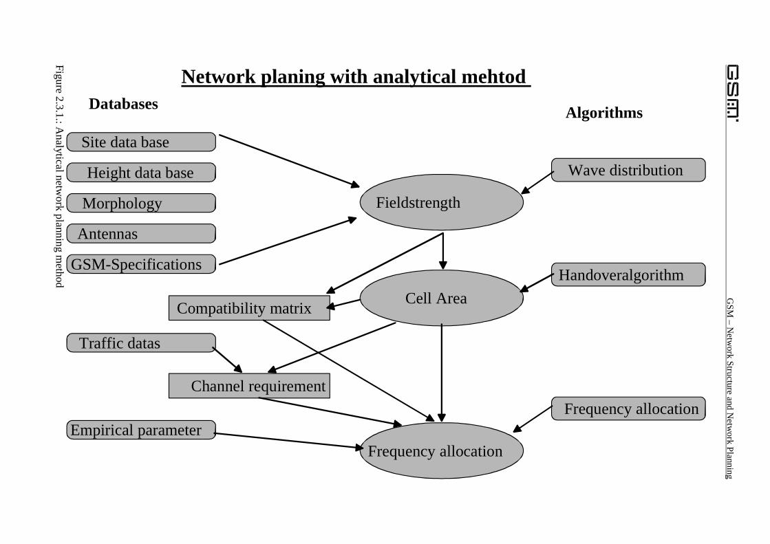
In reality, computer based methods are used for the planning and implementing of BaseTransceiver Stations, taking into account the real conditions like: buildings and cultivation,expected air time, population, wave propagation, etc. Prerequisites of this model are computerbased data bases responsible to build the expert knowledge.
• Site data base: Contains all geographical and technical details of the configuration ofBase Transceiver Stations.
• Altitude: Knows the altitude deployment of the environment of the BTS• Morphology: Cultivation of the ground: water, forests, rivers, etc.• Expected traffic: Because of known measured traffic over the air interface, the network
operator is able to forecast the expected development of the traffic inside his network.This database allows the planning of the dimensions of the network.
• Antennas: The skilful configuration of antennas allows the modification of the wavepropagation over the air. This data base permits an optimisation of the existing network inreal life or in advance of the realisation.
• System parameter: The GSM-Specifications are well known in the calculation algorithmsto allow prediction of the coverage with radio wave field strength and radio link quality.
• Empirical parameters: Most time, network planning is computer work, all the parametersare derived out of simulations. But they can’t replace the reality, the existing knowledgeof the real network is placed inside this data base to enhance the prediction with aid of thesimulation.
• Wave propagation: There are several calculation models to perform the calculation of thewave propagation. Most models are based on 2-dimension, but there are 3-dimensioncalculation algorithms too.
• Handover algorithm: If the computer wants to calculate the cell area sizes it has tosimulate the handover from one cell into the neighbour cell. This algorithm allows thesimulation of handover.
• Frequency allocation: Given by the optimisation problem, to assign a maximum numberof frequency channels to all base station under consideration of the existing assumptionsand conditions.
GSM
– Netw
ork Structure and Netw
ork Planning
Figure 2.3.1.: Analytical netw
ork planning method
Network planing with analytical mehtod Databases Algorithms
Site data base
Height data base
Morphology
Antennas
GSM-Specifications
Empirical parameter
Traffic datas
Compatibility matrix
Channel requirement
Frequency allocation
Fieldstrength
Cell Area
Wave distribution
Handoveralgorithm
Frequency allocation
GSM – Network Structure and Network Planning
Because of the inhomogeneous supply area, in reality, the number of frequency channels percell will differ a lot, depending on the traffic and the cell size. The frequency channels will beassigned among need. The compatibility matrix is presenting the relation and compatibility ofthe radio cells. It contains the guard distance in unit of frequency channels that must beobeyed. E.g. two radio cells have a common channel prohibition, that means, that both cellsare not allowed to use the same frequency channel. Manual entries in this compatibilitymatrix can extend the information gained out of simulation with real knowledge gained out ofmeasurements.
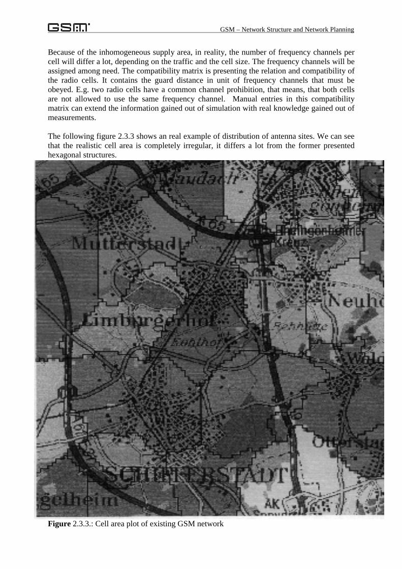
The following figure 2.3.3 shows an real example of distribution of antenna sites. We can seethat the realistic cell area is completely irregular, it differs a lot from the former presentedhexagonal structures.
Figure 2.3.3.: Cell area plot of existing GSM network
GSM – Network Structure and Network Planning
3. Radio Cells
In chapter 1 about the geographical structures within a GSM network it is already mentionedthat one radio cell forms the smallest defined area in the structure and the access point into thenetwork for the users. If the network operator performs a skilful planning of radio cells he canprovide the needed coverage with field strength and capacity. The main job of the radioplanning engineers is the distribution, configuration and optimisation of radio cells. The nextchapter is describing the configuration of every single radio cell, in comparison to the alreadydescribed relating of multiple radio cells.
One radio cell is stretched out by one Base Transceiver Station, BTS, consisting of atransceiver unit combined with an antenna.
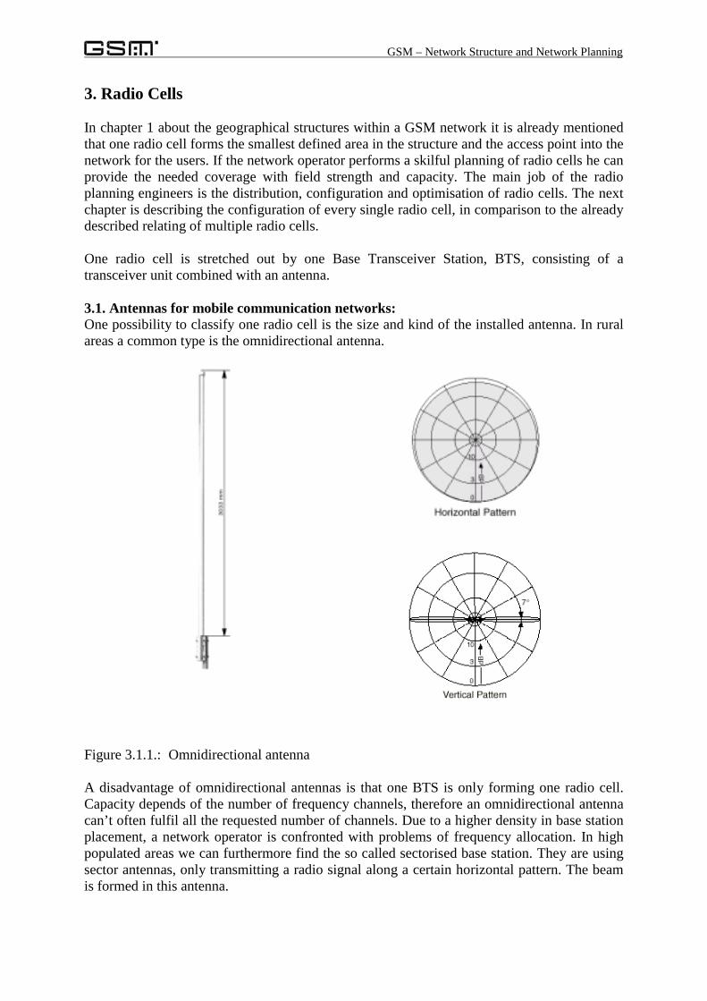
3.1. Antennas for mobile communication networks:One possibility to classify one radio cell is the size and kind of the installed antenna. In ruralareas a common type is the omnidirectional antenna.
Figure 3.1.1.: Omnidirectional antenna
A disadvantage of omnidirectional antennas is that one BTS is only forming one radio cell.Capacity depends of the number of frequency channels, therefore an omnidirectional antennacan’t often fulfil all the requested number of channels. Due to a higher density in base stationplacement, a network operator is confronted with problems of frequency allocation. In highpopulated areas we can furthermore find the so called sectorised base station. They are usingsector antennas, only transmitting a radio signal along a certain horizontal pattern. The beamis formed in this antenna.
GSM – Network Structure and Network Planning
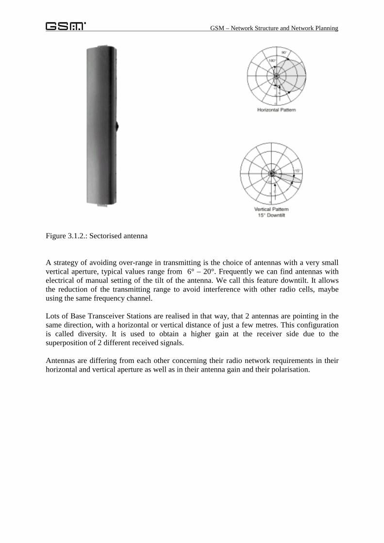
Figure 3.1.2.: Sectorised antenna
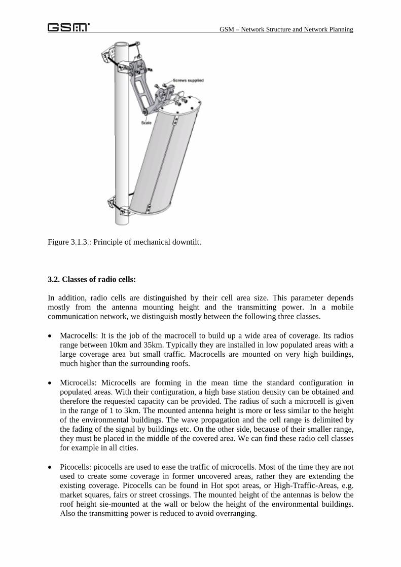
A strategy of avoiding over-range in transmitting is the choice of antennas with a very smallvertical aperture, typical values range from 6° – 20°. Frequently we can find antennas withelectrical of manual setting of the tilt of the antenna. We call this feature downtilt. It allowsthe reduction of the transmitting range to avoid interference with other radio cells, maybeusing the same frequency channel.
Lots of Base Transceiver Stations are realised in that way, that 2 antennas are pointing in thesame direction, with a horizontal or vertical distance of just a few metres. This configurationis called diversity. It is used to obtain a higher gain at the receiver side due to thesuperposition of 2 different received signals.
Antennas are differing from each other concerning their radio network requirements in theirhorizontal and vertical aperture as well as in their antenna gain and their polarisation.
GSM – Network Structure and Network Planning
Figure 3.1.3.: Principle of mechanical downtilt.
3.2. Classes of radio cells:
In addition, radio cells are distinguished by their cell area size. This parameter dependsmostly from the antenna mounting height and the transmitting power. In a mobilecommunication network, we distinguish mostly between the following three classes.
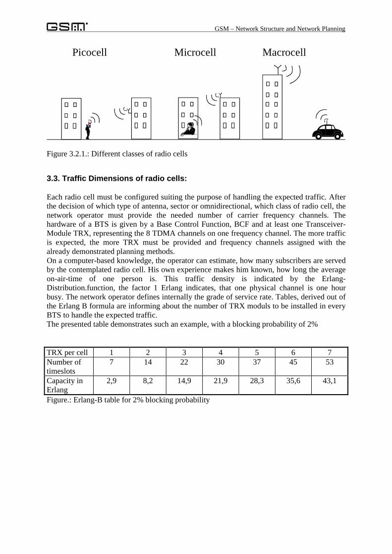
• Macrocells: It is the job of the macrocell to build up a wide area of coverage. Its radiosrange between 10km and 35km. Typically they are installed in low populated areas with alarge coverage area but small traffic. Macrocells are mounted on very high buildings,much higher than the surrounding roofs.
• Microcells: Microcells are forming in the mean time the standard configuration inpopulated areas. With their configuration, a high base station density can be obtained andtherefore the requested capacity can be provided. The radius of such a microcell is givenin the range of 1 to 3km. The mounted antenna height is more or less similar to the heightof the environmental buildings. The wave propagation and the cell range is delimited bythe fading of the signal by buildings etc. On the other side, because of their smaller range,they must be placed in the middle of the covered area. We can find these radio cell classesfor example in all cities.
• Picocells: picocells are used to ease the traffic of microcells. Most of the time they are notused to create some coverage in former uncovered areas, rather they are extending theexisting coverage. Picocells can be found in Hot spot areas, or High-Traffic-Areas, e.g.market squares, fairs or street crossings. The mounted height of the antennas is below theroof height sie-mounted at the wall or below the height of the environmental buildings.Also the transmitting power is reduced to avoid overranging.
GSM – Network Structure and Network Planning
Figure 3.2.1.: Different classes of radio cells
3.3. Traffic Dimensions of radio cells:
Each radio cell must be configured suiting the purpose of handling the expected traffic. Afterthe decision of which type of antenna, sector or omnidirectional, which class of radio cell, thenetwork operator must provide the needed number of carrier frequency channels. Thehardware of a BTS is given by a Base Control Function, BCF and at least one Transceiver-Module TRX, representing the 8 TDMA channels on one frequency channel. The more trafficis expected, the more TRX must be provided and frequency channels assigned with thealready demonstrated planning methods.On a computer-based knowledge, the operator can estimate, how many subscribers are servedby the contemplated radio cell. His own experience makes him known, how long the averageon-air-time of one person is. This traffic density is indicated by the Erlang-Distribution.function, the factor 1 Erlang indicates, that one physical channel is one hourbusy. The network operator defines internally the grade of service rate. Tables, derived out ofthe Erlang B formula are informing about the number of TRX moduls to be installed in everyBTS to handle the expected traffic.The presented table demonstrates such an example, with a blocking probability of 2%
TRX per cell 1 2 3 4 5 6 7Number oftimeslots
7 14 22 30 37 45 53
Capacity inErlang
2,9 8,2 14,9 21,9 28,3 35,6 43,1
Figure.: Erlang-B table for 2% blocking probability
Picocell Microcell Macrocell
GSM – Network Structure and Network Planning
3.4. Network capacity aspects
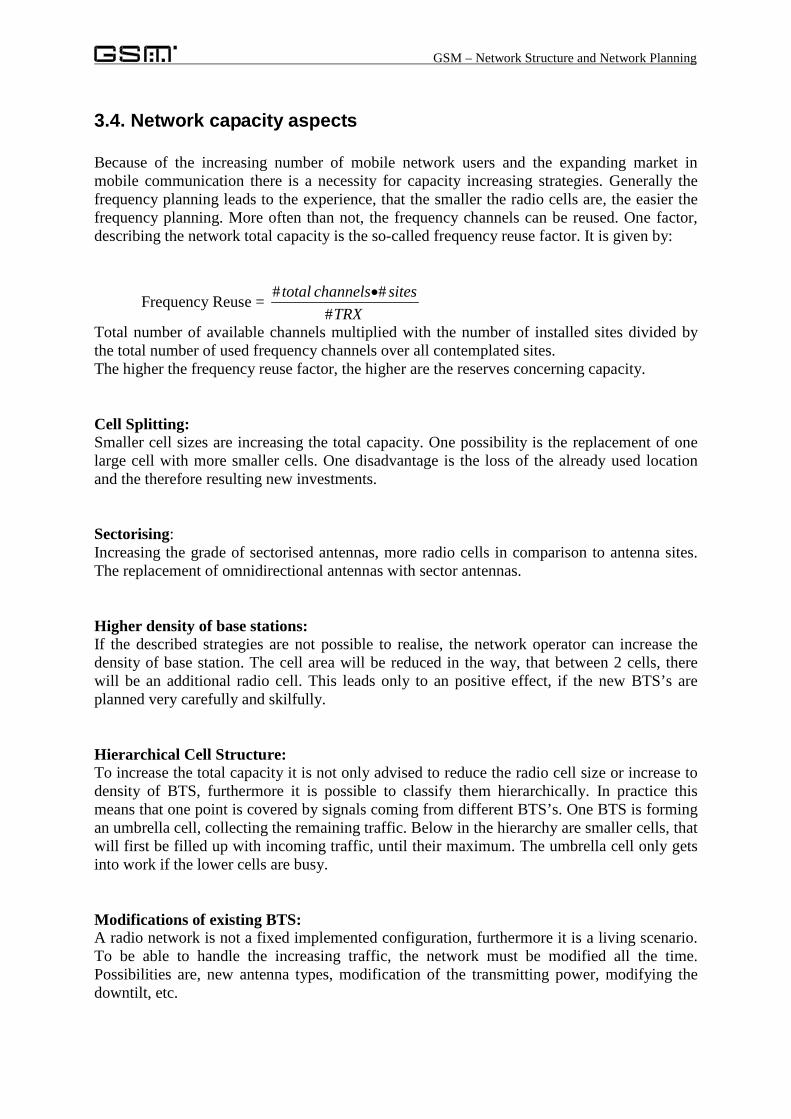
Because of the increasing number of mobile network users and the expanding market inmobile communication there is a necessity for capacity increasing strategies. Generally thefrequency planning leads to the experience, that the smaller the radio cells are, the easier thefrequency planning. More often than not, the frequency channels can be reused. One factor,describing the network total capacity is the so-called frequency reuse factor. It is given by:
Frequency Reuse = TRX
siteschannelstotal#
## •
Total number of available channels multiplied with the number of installed sites divided bythe total number of used frequency channels over all contemplated sites.The higher the frequency reuse factor, the higher are the reserves concerning capacity.
Cell Splitting:Smaller cell sizes are increasing the total capacity. One possibility is the replacement of onelarge cell with more smaller cells. One disadvantage is the loss of the already used locationand the therefore resulting new investments.
Sectorising:Increasing the grade of sectorised antennas, more radio cells in comparison to antenna sites.The replacement of omnidirectional antennas with sector antennas.
Higher density of base stations:If the described strategies are not possible to realise, the network operator can increase thedensity of base station. The cell area will be reduced in the way, that between 2 cells, therewill be an additional radio cell. This leads only to an positive effect, if the new BTS’s areplanned very carefully and skilfully.
Hierarchical Cell Structure:To increase the total capacity it is not only advised to reduce the radio cell size or increase todensity of BTS, furthermore it is possible to classify them hierarchically. In practice thismeans that one point is covered by signals coming from different BTS’s. One BTS is formingan umbrella cell, collecting the remaining traffic. Below in the hierarchy are smaller cells, thatwill first be filled up with incoming traffic, until their maximum. The umbrella cell only getsinto work if the lower cells are busy.
Modifications of existing BTS:A radio network is not a fixed implemented configuration, furthermore it is a living scenario.To be able to handle the increasing traffic, the network must be modified all the time.Possibilities are, new antenna types, modification of the transmitting power, modifying thedowntilt, etc.
GSM – Network Structure and Network Planning
Optimising method at the real networkBecause of the choice and definition of some parameters in the Operation MaintenanceCenter, OMC, it is possible to control the running operation of the network. Some examplesare:
Frequency Hopping:The transfer is not only performed on one timeslot of always the same carrier frequency. Thiscarrier frequency is changed rapidly over the time, it is hopping over different frequencychannels. Possible interference are smoothed regarding their influence. A total reduction ofthe allowed interference level leads to a higher number of assigned frequency channels. Thisstrategy is then called:
TFR, Tighter Frequency Reuse:The principle is, that the in case of frequency hopping, the global carrier to interference ratiocan be reduced, possible interference is distributed over multiple subscribers. In thecompatibility matrix this reduction effects the deleting of some common or adjacent channelinterference relations and the better assignment of frequency channels. The total frequencyreuse factor is smaller-> the total capacity is higher.
Base Station Power Control:New BTS’s are equipped with the ability to control the transmitting power dynamically. In amean or average contemplation, the transmitted power is reduced because of this feature. Thismeans that the network operator can also reduce the active interference potential of theconsidered base station and delete some simulated interference scenarios.
GSM – Network Structure and Network Planning
4. GSM-Network Structure:
The GSM Standard is defining the whole network infrastructure, consisting of hardwarecomponents and protocols between the certain entities. Whole network means that it ispossible to implement a network completely based on the GSM standard, permitting an end-to-end communication. For example, the DECT-standard only describes the interface betweena mobile station and a home based base station. Interfaces and transitions into foreignnetworks out of the GSM network are optional, but they must be implemented to guaranteethe overall availability. This implementation is done by the adaptation of some protocols inthe Interworking Functions, IWF.
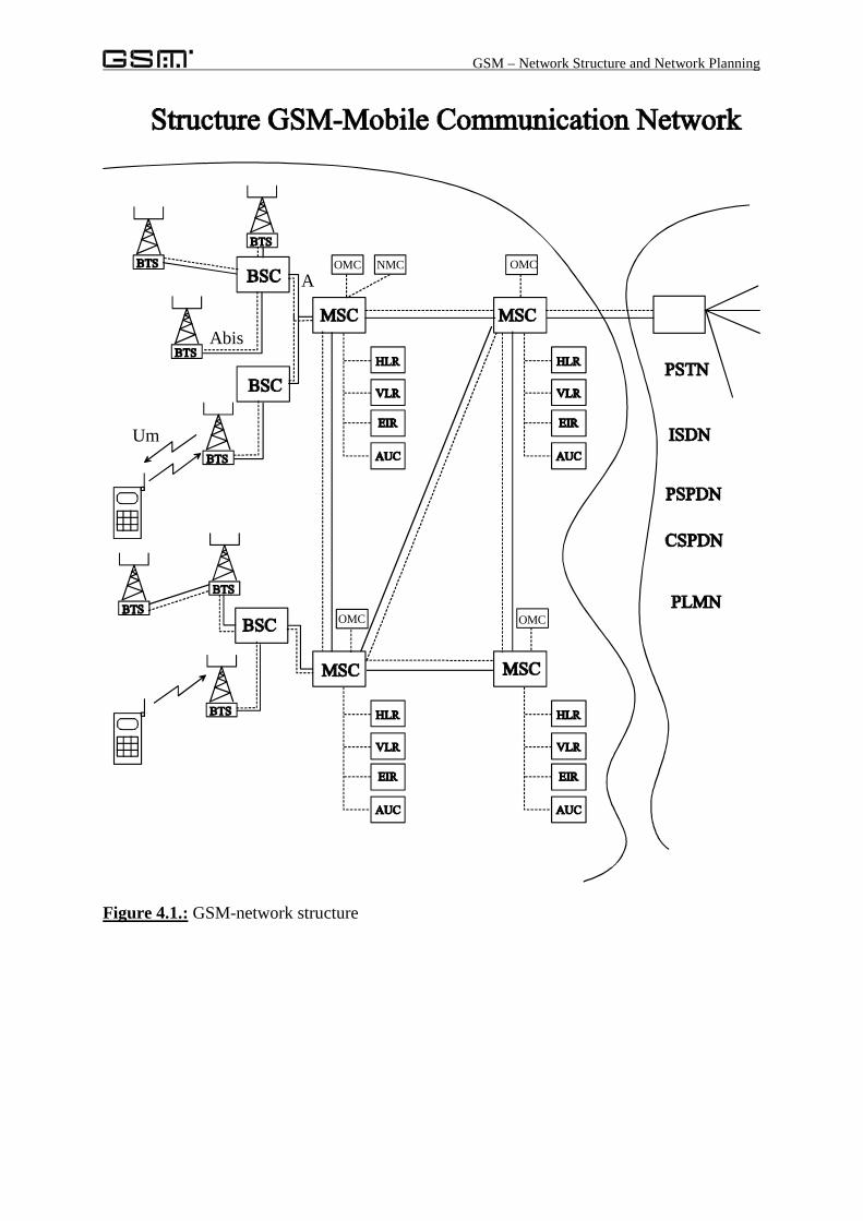
GSM-mobile communication networks are building a hybrid network, consisting of 2subnetworks, a radio network and a core network. There is only one interface that is alwaysrealised as a radio link, the connection between a Mobile Station MS and the fix implementedBase station, BTS.The fix installed GSM network can be subdivided into 3 subnetworks: Base StationSubsystem BSS, Switching and Management Subsystem SMSS and at least the Operation andMaintenance Subsystem OMSS.
4.1. The Mobile Station, MS:Mobile Stations are the electronic devices used by the subscribers to get access to the GSMnetwork. They are also called „Handy“; „Mobile“, „Telefonino“ etc. and they are representingthe mobile part in the Mobile Communication Network. Such an MS is subdivided into 2different parts, a Subscriber Identity Module SIM and a Mobile Equipment ME. The usage ofsuch a SIM card allows the differentiation between subscriber and equipment, the SIM cardpersonalises the Mobile Station and controls the access to the network. A Mobile Station mustperform the complete functions for data transfer over the air interface, e.g. A/D conversion,speech coding, interleaving, modulation, ciphering as well as time and frequencysynchronised transmitting and receiving.We distinguish, regarding the MS the two states: attached and detached, i.e. switched on oroff. In case of a MS that is switched on, we distinguish between idle and dedicated mode, i.e.waiting for a connection or the busy state. A MS can be characterised with its identitynumber, IMEI and the subscriber identities IMSI and MSISDN. There is another chapter:„Tasks of a Mobile Station“, describing all these functions in detail.
GSM – Network Structure and Network Planning
Figure 4.1.: GSM-network structure
OMC NMC OMC
OMC OMC
A
Abis
Um
GSM – Network Structure and Network Planning
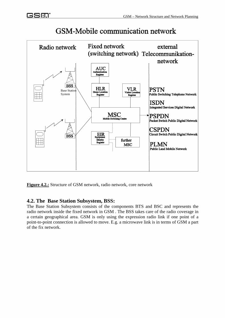
Figure 4.2.: Structure of GSM network, radio network, core network
4.2. The Base Station Subsystem, BSS:The Base Station Subsystem consists of the components BTS and BSC and represents theradio network inside the fixed network in GSM . The BSS takes care of the radio coverage ina certain geographical area. GSM is only using the expression radio link if one point of apoint-to-point connection is allowed to move. E.g. a microwave link is in terms of GSM a partof the fix network.
Base StationSystem
GSM – Network Structure and Network Planning
The Base Transceiver Station BTS:A radio cell is stretched out by a Base Transceiver Station, providing at least one frequencychannel for communication via the air interface. In simplified terms, a BTS consists of aControl and Management Unit an antenna. For each frequency channel, the BTS needs oneTransceiver, TRX. The BCF-Block (Base Control Function) controls all the multipleTransceivers. On the network side, the BTS is representing the air interface. One strategy is toreduce the complexity of the equipment that is installed several times. This is one reason whythe most used functions for control and management are shifted into the BSC.
The Base Station Controller,BSC:The BSC controls and surveys at least one, in real network several BTS’s and is forming theinterface to the MSC. For example, the Handover-scenario is deployed into the BSC, all themanagement of the radio links is implemented in the BSC and the BSC decides about theavailability of radio resources.
4.3. The Switching and Management Subsystem, SMSS:The Switching and Management Subsystem consists of the Mobile Switching Centre MSC ,and the databases: HLR, VLR, AUC and EIR, responsible for the supply of necessaryinformation about subscribers location, profile, authentication and used equipment. This layerperforms the management of the connection. The MSC is responsible that one subscriber getsa connection with another Mobile Station or with another subscriber in a external network.There is a strong separation between BSS and SMSS:
• The Switching Subsystem will never get into a direct connection with an MS, this willalways be performed through to the BSS.
• A Base Station System will never get a connection with external telecommunicationnetworks.
• There is an assignment of one or more BSS’s to every MSC. The conveying of data betweenSMSS and BSS is done via interfaces of the core network, implemented either as cable basedor as microwave links.
The Mobile Switching Centre, MSC:If we want to replace the verb „switching“ with „connecting“ we get the main functionality ofthe MSC. It is responsible for forwarding the call, or connecting the incoming call with theoutcome to guarantee that the two endpoints are connected. It offers, as well, interfaces intoforeign or external networks and connections to other MSC’s of the same network. Incomparison to switching nodes of a fixed communication network, the MSC has to take intoconsideration the assigned physical resource, the mobility of the subscriber and securityfunctions. Each MSC is responsible for the underlying MSC Service Area and is onlyresponsible for the underlying BSC’s and BTS’s that are put in charge of it. To enable theinterworking between the GSM network and the external networks like ISDN, PSTN,PSPDN, the MSC is extended by a so-called Interworking Function, IWF, that is mapping thedifferent protocols onto each other and offers a relay functionality.
GSM – Network Structure and Network Planning
Home Location Register HLR:The HLR is the home register that stores all the information of every subscriber of this homenetwork. In GSM terms, a subscriber is identified by its MSISDN or IMSI number. The HLRforms the access with this number to the relayed information, e.g. home address of the personas well as bank account, etc. One important information inside the HLR is the pointer to thelocation of the mobile subscriber. The HLR is used by every telephone call as a centralregister for routing, location information as well as authentication functionality’s. Thefollowing information can be found inside the HLR:MSISDN, IMSI, restrictions in services, like barring of calls, Supplementary Services, Calldeviation, Address of the valid VLR and MSC. A query at the HLR results in the MSRoaming Number, MSRN, indicating information about the subscriber’s location.
Vistitor Location Register VLR:The Visitor Location Register contains all the information of all mobile stations roaming inthe MSC Service Area. It can be responsible for one MSC or several MSC’s. The VLR isnecessary to avoid an overflow access to the HLR, to establish international roaming and tofasten up the speed during the establishment of a call set-up.In addition, the VLR contains the TMSI number, a temporary identity of the subscriber,assigned only for a short moment of time. This number is used at every access over the airinterface to avoid the transmitting of the fix identity, IMSI and therefore it protects thesubscriber’s identity. As mobility management information, the VLR contains the LAI, theindicator of the serving Location Area, used to page the certain MS. Some data is copied outof the HLR to avoid the access to the HLR at every telephone call. The reasons for this are thedifferent positions. The HLR only exists in the network of the home network operator of onesubscriber, but the VLR describes the information available in the actual serving MSC of theroaming network.
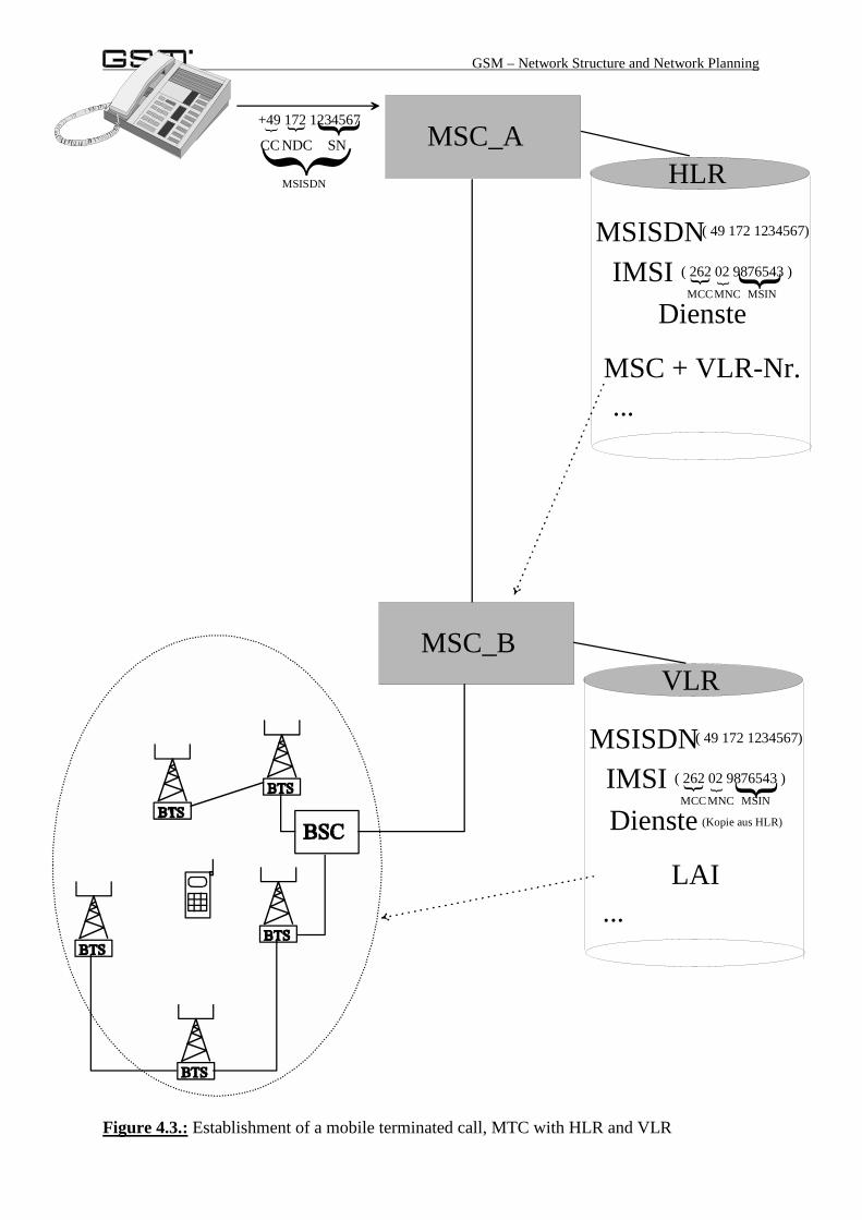
Example for a mobile terminated callThe figure 4.3 is describing the symbolic call establishment between an external caller and amobile user, this scenario is titled as Mobile Terminated Call, MTC. The incoming call isrouted to the Gateway-MSC of the GSM operator, due to the Network Destination Code, NDC. The request in the HLR with the dialled number MSISDN will result in the address of theserving MSC and the VLR number, hidden in the MSRN. The call will be forwarded into thatserving MSC. Network internally, the call will be identified by its TMSI number to protect thesubscribers identity. The VLR contains information about the subscribers location, the LAI.After this step, a paging call over all the BTS’s inside this location area will hopefully get aresponse from the called mobile station. Now the call can be established.
GSM – Network Structure and Network Planning
Figure 4.3.: Establishment of a mobile terminated call, MTC with HLR and VLR
Dienste
MSC + VLR-Nr.
MSC_AHLR
+49 172 1234567{ {{
CC NDC SN
MSISDN( 49 172 1234567)
IMSI ( 262 02 9876543 ){ {{
MCCMNC MSIN
MSISDN
LAI
MSC_BVLR
MSISDN( 49 172 1234567)
IMSI ( 262 02 9876543 ){ {{
MCCMNC MSIN
Dienste (Kopie aus HLR)
...
...
GSM – Network Structure and Network Planning
Authentication Center AUC:The Authentication Centre store secret keys and authentication algorithms assigned to everysingle subscriber. These keys are called Ki, Kc, and the algorithms are called A3 and A8. Thechapter talking about security aspects will give further information about these algorithms.The AUC is calculating in one query step a number of parameter settings that will be storedtemporarily in the HLR and VLR.
Equipment Identity Register EIR:This register is an optional register and its usage depends on the certain network operators. Itcan store in a black, white or grey list all stolen mobile phones, all admitted phones or allphones put into a certain observation. It can be used to avoid theft of Mobile Stations, orallow the adding of special taxes onto Mobile Stations.
4.4. Operation and Maintenance Subsystem OMSS:The current operation of the network is controlled and managed away from the OMSS. TheOperation and Maintenance Centre, OMC survey and controls the whole network. Somefunctions are:• Management and commercial operation (subscriber, terminals, billing, statistic functions,
charging data records, etc.)• Security functionality• Network configuration, network operation and Performance Management• Maintenance and repair of network elements
The control of the whole network can be centralised in one single Network-Management-Centre NMC. The OMSS forms the central Control- and Observation instance to allow thetechnical staff of the operator the whole control and maintenance of the GSM network.