gsm multi function controller and monitoring system...
TRANSCRIPT
GSM MULTI FUNCTION CONTROLLER
AND MONITORING SYSTEM
Model: GSM-220
GSM-220 User Manual (V1.1)
2 | P a g e
Table of Contents
About the Product……………………………………………..…………………………………………4
Product Specification……………………………………………………………………………………4
Package Contents……………………………………………………………………………..………….5
Device Design……………………………………………………………………….………………………5
Installation Diagram……………………………………………………………………………………..5
Connection Details…………………………………………………………………………………….…6
Setup Instruction………………………………………………………………………………………….6
1 Administrator
1.1 Temporary Administrator Privilege……………………………………………………………………………………….7
1.2 Changing a Password…………………………………………………………………………………………………………….7
1.3 Add an Administrator Number……………………………………………………………………………………..……….8
1.4 Enquiry to Administrator Numbers in the list………………………………………………………………………..8
1.5 Delete Administrator Number in the list……………………………………………………………………………….8
1.6 Enquiry Signal Strength………………………………………………………………………………………………………...8
1.7 Enquiry Time for the System………………………………………………………………………………………………...8
1.8 Set Time for the System…………………………………………………………………………………………..……………8
1.9 Switch ON/OFF for SMS Text Message………………………………………………………………………………….9
1.10 Switch ON/OFF for Call…………………………………………………………………………………………………….……9
1.11 Time Schedule to send SMS reminder to the Administrator…………………………………………….…...9
1.12 SMS Text Message / Call when System Start………………………………………………………………………...9
1.13 Input Message for the System Start / Time Schedule SMS Reminder…………………………………..10
1.14 Input Message for Command Control………………………………………………………………………………….10
1.15 Enquiry Input Message for Command Control……………………………………………………………….……10
1.16 Restart System………………………………………………………………………………………………………………….…11
2 Relay Programming
2.1 Relay 1 Control (Main Relay)……………………………………………………………………………………………….11
2.1.1 Main control of the relay for a pre-determined time…………………………………………………………..11
2.2 Enquiry Relay Status (Main Relay, Sub Relay)………………………………………………………………………11
2.3 Received SMS Report when Control Relay is activated. Not receiving a SMS report when
Control Relay is off………………………………………………………………………………………………………………11
2.4 Time Delay For Main Relay………………………………………………………………………………………………....12
2.5 Time Delay For Relay 2 (Sub Relay)………………………………………………..……………………………………12
2.6 Relay Working Method………………………………………………………….……………………………………………12

GSM-220 User Manual (V1.1)
3 | P a g e
2.7 Sub Relay Control………………………………………………………………..………………………………………………13
2.7.1 Control of the sub relay for a predetermined time ……..……..………………………………………………14
2.8 Control Master Alarm Alert For System…………………………………………………….…………………………14
2.9 Enquiry For Master Alarm Alert Status………………………………………………………………………………..14
2.10 Call Alert For Trigger Type Alarm………………………………………………………………………….……………..14
2.11 Trigger Type Alarm Link with Relay……………………………………………………………………………..………15
3 Power Outage Alert Programming
3.1 Power Outage Delay Time………………………………………………………………………………………………..…15
3.2 Input Message For the Power Outage Alert……………………………………………………….……………….16
3.3 Reset to Default Message for the Power Outage Alert………………………………………….…………….16
3.4 Input Message for the Recovery from Power Outage………………………………………………………....16
3.5 Reset to Default Message for the Recovery from Power Outage…………………………………………16
4 Input Programming
4.1 Input Trigger Mode………………………………………………………………………………………………………..……16
4.2 Input Alarm Delay Time………………………………………………………………………………………………………17
4.3 Alarm Text For Inputs………………………………………………………………………………………………………….17
4.4 Recover Text For Inputs………………………………………………………………………………………………………17
5 Programming And Maintenance Of The Guest List
5.1 Create a Group Under The Guest List ……………………………………………………….…………………..……17
5.2 To Add Phone Number To a Group……………………………………………………………………………………..17
5.3 Check Numrer In a Group ………………………………………….……………………………………………………….18
5.4 Delete Phone Number In a group ……………………………………………………………………………….………18
5.5 Delete a group ……………………………………………………………………………………………………………………18
5.6 Delete Complete Guest List ………………………………………………..………………………………………………18
5.7 Change Group Name …………………………………………………………………………………………………….……18
5.8 Checking guest access …………………………………………………………..……………………………………………18
GSM-220 User Manual (V1.1)
4 | P a g e
About Product
This system incorporates 2 digital inputs, they can be set to give alarm when a short circuit or when they
break, you have here the opportunity to make delay of alarms by up to 6553 seconds. The unit will also
let you know when an alarm disappears. Alarms can be given in the form of text messages and or call for
administrators. The relays can also be controlled by alarms on input, so you have the opportunity to use
them for different control purposes.
2 relays Max. 24 Volt 1 Amp. with NC / NO function; the relays can be controlled via calls to the device,
via text messages and alarms from temperature part as well as digital input.
The unit also includes AC Loss alarm, it will send alarm to the administrator if a power failure occurs, the
alarm can be delayed with Max. 6553 seconds, the alarm can be given as SMS and or call, and by activating
relays.
The device is equipped with 7.2 Volt Lion backup battery, it will keep the unit running in 6-10 hours when
the battery drops below 20% it will notify administrators such via SMS.
The unit can have up to 5 administrators who want to get alarms, and will be able to make the
programming of the unit, these administrators can be changed via SMS messages.
All administrator always has full access to the device.
For service personnel, they can use the device for the temporary Administrator rights by sending the SMS
with the device's password so that you will obtain administrator rights for 10 minutes, very useful for
installers, etc.
Power supply 12 Volt DC.
Product Specification
• Operation Voltage: 12VDC
• Operating Current: Max. 300mA, typically 35mA
• Number Of I/O: 2 Dry Contact Input, 2 Relay Output
• Relay Contacts Capacity: NC: 1A@24VDC, NO: 2A@120VAC/24VDC
• GSM Frequency: GSM900/1800Mhz (Optional GSM850/900/1800/1900Mhz)
• Humidity: Less Than 80% RH
• Operating Temperature: -20°C to 55°C
• Casing: DIN Rail Casing
• Physical Casing Dimension: 88mm X 72mm X 59mm
GSM-220 User Manual (V1.1)
5 | P a g e
Package Contents
The package contains the following items;
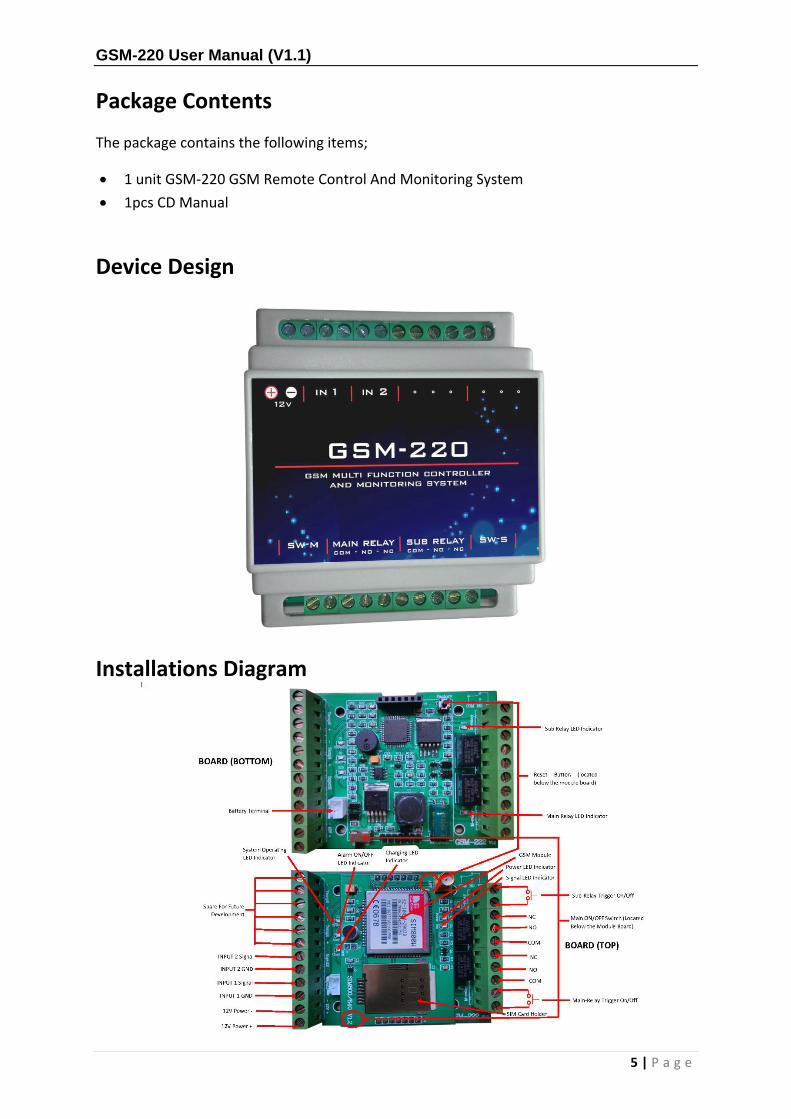
1 unit GSM-220 GSM Remote Control And Monitoring System
1pcs CD Manual
Device Design
Installations Diagram

GSM-220 User Manual (V1.1)
6 | P a g e
The two screw terminals on each side of the relay connection is to control Main relay, and
Sub relay at a short circuit terminal, the relay will cut at the time which you have programmed
it to under point 2.4
Connection Details
Co
nn
ect
or
12
Spare For Future Development
11
Sub Relay Trigger On/Off
13
Co
nn
ecto
r
10
14
9
Sub Relay NC
15
8
Sub Relay NO
16
7
Sub Relay COM
17
6
INPUT 2 Signal Main Relay NC
18
5
INPUT 2 GND
Main Relay NO
19
4
INPUT 1 Signal
Main Relay COM
20
3
INPUT 1 GND
Main Relay Trigger On/Off
21
2
12V POWER - 2
2
1
12V POWER +
Setup Instructions
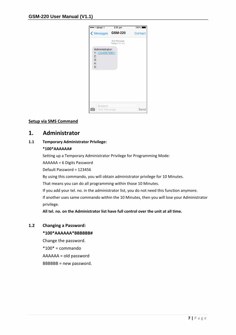
Setup Administrator by phone call
The GSM-220 is easy to setup by just insert the SIM card, switch on the power, and using your
mobile phone to call to the unit. The first called mobile phone number to the unit will
automatically become a registered first Administrators
This can be done each time the device has been "factory reset"
Example you are using the phone number: 12345678901 to call to the GSM-220.
Replied SMS message from the unit as per below;
GSM-220 User Manual (V1.1)
7 | P a g e
Setup via SMS Command
1. Administrator
1.1 Temporary Administrator Privilege:
*100*AAAAAA#
Setting up a Temporary Administrator Privilege for Programming Mode:
AAAAAA = 6 Digits Password
Default Password = 123456
By using this commando, you will obtain administrator privilege for 10 Minutes.
That means you can do all programming within those 10 Minutes.
If you add your tel. no. in the administrator list, you do not need this function anymore.
If another uses same commando within the 10 Minutes, then you will lose your Administrator
privilege.
All tel. no. on the Administrator list have full control over the unit at all time.
1.2 Changing a Password:
*100*AAAAAA*BBBBBB#
Change the password.
*100* = commando
AAAAAA = old password
BBBBBB = new password.

GSM-220 User Manual (V1.1)
8 | P a g e
1.3 Add an Administrator Number:
*101*A*BBBBBB#
Add administrators to the Administrator List
*101* commando
A = Administrator no- (1 – 5)
BBBBBBBB = Tel. no. of new administrator.
You can add a Minimum of 3 digits and a maximum of 20 digits.
1.4 Enquiry to the Administrator Numbers in the list:
*102#
Check administrator list
It will reply with a full list of all administrators on the list.
1.5 Delete Administrator Number in the list:
*103*A#
Deleting administrator tel. no. on the list
*103* = commando
A = administrator no. (1 – 5)
1.6 Enquiry Signal Strength:
*104#
Check signal strength on the GSM connection
Enquiry for Signal Strength
CSQ = 0 – 10 (Weak Signal)
CSQ = 11- 20 (Average Signal)
CSQ = 21 – 30 (Good Signal)
CSQ = Above 30 (Excellent Signal)
1.7 Enquiry Time for the System:
*105#
Check time already stored in the unit.
1.8 Set Time for the System:
*106#
By sending *106# the unit will be updated with the same time as in the SMS text.
GSM-220 User Manual (V1.1)
9 | P a g e
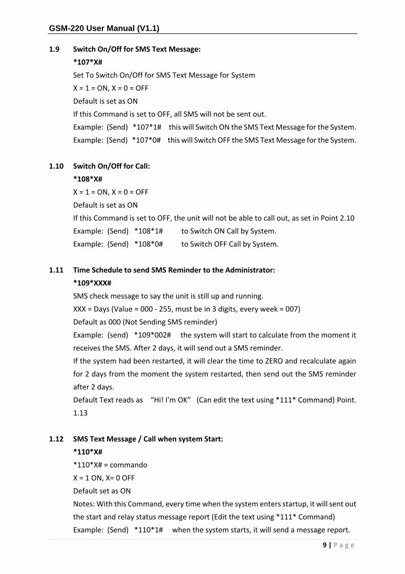
1.9 Switch On/Off for SMS Text Message:
*107*X#
Set To Switch On/Off for SMS Text Message for System
X = 1 = ON, X = 0 = OFF
Default is set as ON
If this Command is set to OFF, all SMS will not be sent out.
Example: (Send) *107*1# this will Switch ON the SMS Text Message for the System.
Example: (Send) *107*0# this will Switch OFF the SMS Text Message for the System.
1.10 Switch On/Off for Call:
*108*X#
X = 1 = ON, X = 0 = OFF
Default is set as ON
If this Command is set to OFF, the unit will not be able to call out, as set in Point 2.10
Example: (Send) *108*1# to Switch ON Call by System.
Example: (Send) *108*0# to Switch OFF Call by System.
1.11 Time Schedule to send SMS Reminder to the Administrator:
*109*XXX#
SMS check message to say the unit is still up and running.
XXX = Days (Value = 000 - 255, must be in 3 digits, every week = 007)
Default as 000 (Not Sending SMS reminder)
Example: (send) *109*002# the system will start to calculate from the moment it
receives the SMS. After 2 days, it will send out a SMS reminder.
If the system had been restarted, it will clear the time to ZERO and recalculate again
for 2 days from the moment the system restarted, then send out the SMS reminder
after 2 days.
Default Text reads as “Hi! I'm OK” (Can edit the text using *111* Command) Point.
1.13
1.12 SMS Text Message / Call when system Start:
*110*X#
*110*X# = commando
X = 1 ON, X= 0 OFF
Default set as ON
Notes: With this Command, every time when the system enters startup, it will sent out
the start and relay status message report (Edit the text using *111* Command)
Example: (Send) *110*1# when the system starts, it will send a message report.

GSM-220 User Manual (V1.1)
10 | P a g e
Example: (Send) *110*0# when the system starts, it will not send a message report.
1.13 Input Message for the System Start / Time Schedule SMS Reminder:
*111*AAAAAAAAA#
*111* = commando
AAAAAAAAAA = the text that will be send when unit startup, and/if was send a remind
message, saying unit is still up and running.
Example: (Send) *111*I'm alive# once the system starts, “I'm alive” message will be
sent to the Administrator. When using the Time Schedule Function, it will send “Hi!
I'm alive” to the Administrator.
Notes: the Message without “Hi” Will be the message for System Start. Message with
“Hi” Will be the message for Time Schedule SMS Reminder under *109*
1.14 Input Message for Command Control:
*112*XX*”AAA””BBB”
Change commandos to user specified commands.
So *112* = commando
XX is command no, there is 32 available 01-32
“AAAAA” is existing commando
“BBBBB” is new commando.
For an example: change Check signal strength. (Send) *104# to just signal!
Then you have to send the following message. (Send) *112*01*”*104#””signal”
01 = commando no. 1
“*104#” = existing commando for check signal strength.
“signal” = new commando for check signal strength.
To delete this simple wording replacement command, you can (send)
*112*01*”*104#””” or *112*01*”””” or *112*01*”””signal” the group 01 will now
become blank.
1.15 Enquiry Input Message for command Control:
*113*XX#
Check the commandos there have been changed.
Enquiry Input Message for Controller
XX = Group (Value 01 – 32, must be in 2 digits)
Example: 03 is group 03.

GSM-220 User Manual (V1.1)
11 | P a g e
1.16 Restart System
*114#
This is for restarting the system,
Remember: “Hi I´m OK” this system message will be RESET and start counting days
again beginning with 1.
2. RELAY programming
2.1 Relay 1 control (Main relay)
*200*X#
X = 0 or 1 (0 = OFF, 1 = ON)
Example: (Send) *200*1# the relay will be set to ON, and Recover text for Inputs:
Example: (Send) *200*0# the relay will be set to Off and a report message will be
sent.
Notes: Relay working mode for 01, 02, 03, 06, 07, 08 which work together with
Command *205*
2.1.1 Main control of the relay for a pre-determined time
*2001*XXXX#
XXXX = time in seconds (0001 – 6553 seconds, always 4 digits, 10 seconds = 0010 etc.)
For example, You want Main relay to activate for 5 minutes, then sends *2001*0300#,
the Main relay activate for 5 minutes and then automatically off again.
Notes: Relay working mode for 04, 05, 09, 10 which work together with Command
*205*
2.2 Enquiry Relay Status (Main relay, Sub relay)
*201#
Get an SMS with the status of Main Relay and Sub Relay
2.3 Received SMS Report when activated. Not receive SMS report when Control Relay is
off.
*202*X#
X = 0 or 1 (0 = OFF, 1 = ON)
Default is 1
1 = receive SMS when call unit for activate relay 1
0 = not receive SMS when call unit for activate relay 1

GSM-220 User Manual (V1.1)
12 | P a g e
2.4 Time Delay for Main relay:
*203*XXXX#
XXXX = time in seconds (0001 – 6553 seconds, always 4 digits)
Default is 0001 (1 second)
Notes: Relay working mode for 04,05,09, 10 work together with Command *205*
Notes: When the relay as not yet returned back to actual status, there is another
trigger. The time delay will be: previous actual delay time + current delay time
Example: When working on 04 or 05 status, the delay is for 25 seconds. The system
will calculate up to 24 seconds, it then receives another call, total delay time will be
(24 + 25 = 49 seconds), and the relay will then go back to its actual status.
2.5 Time Delay for Sub Relay
*204*1*XXXX#
*204*1* = (is the commando)
XXXX = time in seconds (0001 – 6553 seconds, is always 4 digits)
Default is 0001 (1 second)
Notes: Relay working mode for 09, 10 work together with Command *205*
Example: (Send) *204*1*0005# which means relay 2 delays for 5 seconds and then
returns back to normal status. One phone call, the system will answer, press 1 key, the
relay will delay for 5 seconds and then return back to normal status.
2.6 Relay Working Method
*205*XX#
XX = Working Condition (Value 01 - 12)
Default is 03
Explanation for Working Condition
01 = After System Start, Relay Condition as ON Status. When receive Call, System will
terminal the Call, and Relay will trigger
02 = After System Start, Relay Condition as OFF Status. When receive Call, System will
terminal the Call, and Relay will trigger
03 = After System Start, Relay Condition as LAST Action before the system OFF. When
receive Call, System will terminal the Call, and Relay will trigger
04 = After System Start, Relay Condition as OFF Status. When receive Call, System will
terminal the Call, and Relay will ON, After Delay Time (N will depend on *203*
command), then relay will OFF
05 = After System Start, Relay Condition as ON Status. When receive Call, System will
terminal the Call, and Relay will OFF, After Delay Time (N will depend on *203*
command), then relay will ON

GSM-220 User Manual (V1.1)
13 | P a g e
06 = After System Start, Relay Condition as ON Status. When receive Call, System will
answer the Call, Press 0-N, the corresponding number of Relay will trigger
07 = After System Start, Relay Condition as OFF Status. When receive Call, System will
answer the Call, Press 0-N, the corresponding number of Relay will trigger
08 = After System Start, Relay Condition as LAST Action before the system OFF. When
receive Call, System will answer the Call, Press 0-N, the corresponding number of Relay
will trigger
09 = After System Start, Relay Condition as OFF Status. When receive Call, System will
answer the Call, Press 0-N, the corresponding number of Relay will ON, After Delay
Time (N will depend on *203* command), then relay will OFF
10 = After System Start, Relay Condition as ON Status. When receive Call, System will
answer the Call, Press 0-N, the corresponding number of Relay will OFF, After Delay
Time (N will depend on *203* command), then relay will ON
11 = After System Start, Relay Condition as OFF Status. Relay will be Control by the
Sensor (Depend on the Setting of Command of *304*). Cannot Manually Control the
Relay
12 = After System Start, Relay Condition as ON Status. Relay will be Control by the
Sensor (Depend on the Setting of Command of *304*). Cannot Manually Control the
Relay"
NOTEs: activating by calling subject to Main Relay only except under Mode 9 and Mode
10
2.7 Sub Relay Control:
*207*A#
*207* = (is the Commando)
A = 0 or 1 (0 = OFF, 1 = ON)
Example: (send) *207*1# which means the Sub relay is ON
Example: (send) *207*0# which means the Sub relay is OFF
Notes: Work together with Command *205* of 01, 02, 03, 06, 07, 08
GSM-220 User Manual (V1.1)
14 | P a g e
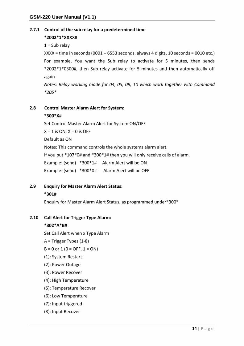
2.7.1 Control of the sub relay for a predetermined time
*2002*1*XXXX#
1 = Sub relay
XXXX = time in seconds (0001 – 6553 seconds, always 4 digits, 10 seconds = 0010 etc.)
For example, You want the Sub relay to activate for 5 minutes, then sends
*2002*1*0300#, then Sub relay activate for 5 minutes and then automatically off
again
Notes: Relay working mode for 04, 05, 09, 10 which work together with Command
*205*
2.8 Control Master Alarm Alert for System:
*300*X#
Set Control Master Alarm Alert for System ON/OFF
X = 1 is ON, X = 0 is OFF
Default as ON
Notes: This command controls the whole systems alarm alert.
If you put *107*0# and *300*1# then you will only receive calls of alarm.
Example: (send) *300*1# Alarm Alert will be ON
Example: (send) *300*0# Alarm Alert will be OFF
2.9 Enquiry for Master Alarm Alert Status:
*301#
Enquiry for Master Alarm Alert Status, as programmed under*300*
2.10 Call Alert for Trigger Type Alarm:
*302*A*B#
Set Call Alert when x Type Alarm
A = Trigger Types (1-8)
B = 0 or 1 (0 = OFF, 1 = ON)
(1): System Restart
(2): Power Outage
(3): Power Recover
(4): High Temperature
(5): Temperature Recover
(6): Low Temperature
(7): Input triggered
(8): Input Recover
GSM-220 User Manual (V1.1)
15 | P a g e
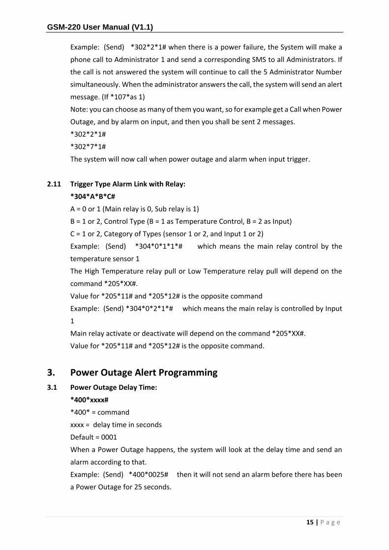
Example: (Send) *302*2*1# when there is a power failure, the System will make a
phone call to Administrator 1 and send a corresponding SMS to all Administrators. If
the call is not answered the system will continue to call the 5 Administrator Number
simultaneously. When the administrator answers the call, the system will send an alert
message. (If *107*as 1)
Note: you can choose as many of them you want, so for example get a Call when Power
Outage, and by alarm on input, and then you shall be sent 2 messages.
*302*2*1#
*302*7*1#
The system will now call when power outage and alarm when input trigger.
2.11 Trigger Type Alarm Link with Relay:
*304*A*B*C#
A = 0 or 1 (Main relay is 0, Sub relay is 1)
B = 1 or 2, Control Type (B = 1 as Temperature Control, B = 2 as Input)
C = 1 or 2, Category of Types (sensor 1 or 2, and Input 1 or 2)
Example: (Send) *304*0*1*1*# which means the main relay control by the
temperature sensor 1
The High Temperature relay pull or Low Temperature relay pull will depend on the
command *205*XX#.
Value for *205*11# and *205*12# is the opposite command
Example: (Send) *304*0*2*1*# which means the main relay is controlled by Input
1
Main relay activate or deactivate will depend on the command *205*XX#.
Value for *205*11# and *205*12# is the opposite command.
3. Power Outage Alert Programming
3.1 Power Outage Delay Time:
*400*xxxx#
*400* = command
xxxx = delay time in seconds
Default = 0001
When a Power Outage happens, the system will look at the delay time and send an
alarm according to that.
Example: (Send) *400*0025# then it will not send an alarm before there has been
a Power Outage for 25 seconds.

GSM-220 User Manual (V1.1)
16 | P a g e
3.2 Input Message for the Power Outage Alert:
*401*AAAAAAAAAAAA#
*401* = command
AAAAAAAAAAAAAAA = text for power outage alarm (max 100 characters)
The alarm text Administrators will receive when there is a Power Outage alarm
Example: (Send) *401*Power cut# when power outage, “Power cut” message will be
sent to the administrators.
3.3 Reset to Default Message for the Power Outage Alert:
*401*#
The commandos to Reset Power Outage alarm will text back to Default.
Default text is “AC power down”
3.4 Input Message for the Recovery from Power Outage:
*402*AAAAAAAAAAAAAA#
*402* = commando
AAAAAAAAAAAAAAA = text for power recover
Example: (Send) *402*Power recover# when power supply recover happens,
“Power recover” message will be sent to the administrators.
3.5 Reset to Default Message for the Recovery from Power Outage:
*402*#
Reset Power recovery alarm will be text to Default
Default text (AC power up)
4. Input Programming
4.1 Input Trigger Mode:
*700*XX#
XX = working mode 0 or 1
0 = terminals when connected, will send an alarm.
1 = terminals when disconnected, will send an alarm.
Example: (Send) *700*10# this means that when both terminals in Input 1 are
connected, then suddenly they are disconnected, it will send out an Alarm. When both
terminals in Input 2 are disconnected, then suddenly they are connected, it will send
out an Alarm.

GSM-220 User Manual (V1.1)
17 | P a g e
4.2 Input Alarm Delay Time:
*702*A*BBBB#
A = Input 1 or 2
BBBB = time in seconds, Max. 6553 seconds. (Always in 4 figures, 1 second = 0001)
This function will delay the alarm, from when an input is triggered, and until it sends
the Alarm.
Example: (Send) *702*1*0025# when Input 1 is triggered, it will not send an alarm,
until 25 seconds after.
4.3 Alarm Text for Inputs:
*703*A*BBBBBBBBBBBBB#
A = Input 1 or 2
BBBBBBBBBB = the text there will be sent when an input is triggered.
Example: (send) *703*1*Tank full# when input 1 is triggered a message will be
sent saying “tank full”.
4.4 Recover Text for Inputs:
*704*A*BBBBBBBBBB#
A = Input 1 or 2
BBBBBBBBB = a text will be sent when an input recovery happens.
Example: (send) *704*1*Tank not full# when input 1 is not triggered a message
will be sent saying “tank not full”.
5. Programming And Maintenance Of The Guest List
5.1 Create a Group Under The Guest List
*800*XXXXXXX*YYYYYYYY#
XXXXXXX = Name of the group(Max: 7 char)
YYYYYYYY = telephone NO. (Min: 3 digits, Max: 15 digits)
For example, Send *800*001*12345678# then there will be a new group called 001.
And first number in the Group 001 is 12345678
5.2 To Add Phone Number To a Group
Then you use the same command
*800*001*YYYYYYYY#
So, this is the second (2) number in the Group 001
GSM-220 User Manual (V1.1)
18 | P a g e
5.3 Check Numrer In a Group
*801*XXXXXXX#
XXXXXXX = the Group Name
For example, To check number In the Group 001, you send *801*001#
Then the system will send an SMS with all No. programmed in Group 001
5.4 Delete Phone Number In a group
*802*XXXXXXX*Z#
XXXXXXX = the group name
Z = Number On the list (1-8)
For example, Send *802*001*1# then the system will delete telephone number for
the list number 1 in the group 001.
When all numbers in a group is deleted, the system will automatically delete the
group.
5.5 Delete a group
*803*XXXXXXX#
XXXXXXX = Group Name
For example, Send *803*001# then the whole group 001 with any telephone number
will be delete.
5.6 Delete Complete Guest List
*804#
For example, Send *804# then the entire guest list will be deleted in the system,
including all groups.
5.7 Change Group Name
*805*XXXXXXX*YYYYYYY#
XXXXXXX = Old Name
YYYYYYY = new name (Max: 7 char)
For example, Send *805*001*Club# will Group 001 now called Club
5.8 Checking guest access
*208*X#
X = 1 or 0
0 = "open mode" all callers to the unit will activate the Main relay.
1 = "safe mode" only the call from administrators and phone number on the guest list
can activate the main relay.
GSM-220 User Manual (V1.1)
19 | P a g e
NOTEs
Phone number on the guest list can call the system and activate the Main relay
programmed in section 2.4 of section 2.6
The guest list can contain up to 125 groups.
Each group can contain up to 8 telephone no. (Min. 3 digits, Max. 15 digits)
If you try to send more than 8 phone numrer to a group, the system will announce full.
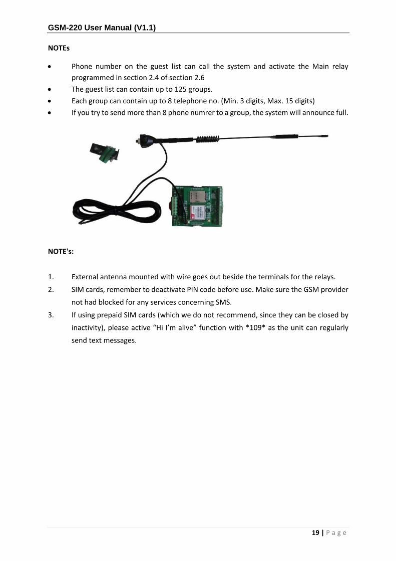
NOTE's:
1. External antenna mounted with wire goes out beside the terminals for the relays.
2. SIM cards, remember to deactivate PIN code before use. Make sure the GSM provider
not had blocked for any services concerning SMS.
3. If using prepaid SIM cards (which we do not recommend, since they can be closed by
inactivity), please active “Hi I’m alive” function with *109* as the unit can regularly
send text messages.