gsi online for leica tpsw3.leica-geosystems.com/media/new/product_solution/gsi...a simple command...
TRANSCRIPT

Advanced User GuideGeosystems
GSI ONLINE for Leica TPSM. Mueller

2
Introduction
Controlling electronic Total Stations with remote interface devices opens a big, newsection in the world of surveying applications. Exchanging data and configurationsbetween instruments and computers or transferring data directly to a data loggerhighly enhances the flexibility and functionality of Leica’s sensors. The latest TPSTotal Stations, as well as previous series support a large set of interfacing com-mands, to allow direct user access via RS232 serial interface.
The Leica Geo Serial Interface (GSI) is a general purpose, serial data interface forbi-directional communication between TPS Total Stations and computers. GSI usesa simple command structure to read/write values from/to the sensor. Global and in-strument specific word indexes (WI) are used to specify various data types. De-pending on the type of Total Station used, GSI provides a specific set of commandsconsidering the instrument series functionality.
In addition to the former online reference guide „WILD INSTRUMENTS ONLINE“,this User Guide focuses the latest Leica Series of Total Stations -TPS100/300/700/1000/1100. We have designed this guide as a simple commandlisting and therefore basic aspects of serial data communications will not be covered.For detailed information and advice on GSI communication, we strongly recommendto consult the „WILD INSTRUMENTS ONLINE“.
Marco MuellerBusiness Area TPS

3
Table of contents
GSI Data Format............................................................................................. 4
GSI Block Information ..................................................................................... 5
Online Command Structure............................................................................. 6
TPS100 Commands........................................................................................ 7
SET ..................................................................................................... 8
CONF ................................................................................................ 10
PUT ................................................................................................... 12
GET................................................................................................... 13
Remote Stake out.............................................................................. 14
Warning and Errors ........................................................................... 15
TPS300/700 Commands............................................................................... 16
SET ................................................................................................... 17
CONF ................................................................................................ 20
PUT ................................................................................................... 23
GET................................................................................................... 25
Warning and Errors ........................................................................... 27
TPS1000/1100 Commands........................................................................... 28
SET ................................................................................................... 29
CONF ................................................................................................ 31
PUT ................................................................................................... 33
GET................................................................................................... 34
Telescope positioning ........................................................................ 36
Warning and Errors ........................................................................... 37

GSI Data Format
4
GSI Data Format
Data transmitted trough GSI interface is composed in a sequence of blocks, ending with a terminator(CR or CR/LF). Every block (see the GSI8 example below) starts with a two character WI code, speci-fying the data type within this block. So far, a GSI8 block consists of totally 15 characters, including 7information characters (e.g. WI, sign) and 8 (GSI8) data characters. Since data had become largerthan 8 characters, we have introduced an enhanced 16 character data format, called GSI16. This newformat size considers large scaled values, such as UTM coordinates, large alphanumeric codes, attrib-utes or pointnumbers. Following, a GSI8 example showing a sequence of three blocks, containingpointnumber (11), easting coordinate (81) and northing coordinate (82). Example 2, shows a GSI16block sequence with pointnumber (11), horizontal (21) and vertical (22) angle.
Example GSI8:
110001+0000A110 81..00+00005387 82..00-00000992110002+0000A111 81..00+00007586 82..00-00003031110003+0000A112 81..00+00007536 82..00-00003080110004+0000A113 81..00+00003839 82..00-00003080110005+0000A114 81..00+00001241 82..00-00001344 ← 8ch.→
GSI8 Datablock Structure:
Pos.1-2: Word Index (WI) e.g. “11”; WI codePos.3-6: Information related to data e.g. “0002”; number of linesPos.4: Sign e.g. + or -Pos.8-15: GSI8 data (8 digits) e.g. “0000A113”; PointnumberPos.16: Blank (=separating character)
Example GSI16:
110001+000000000PNC0055 21.002+0000000013384650 22.002+0000000005371500110002+000000000PNC0056 21.002+0000000012802530 22.002+0000000005255000110003+000000000PNC0057 21.002+0000000011222360 22.002+0000000005433800110004+000000000PNC0058 21.002+0000000010573550 22.002+0000000005817600110005+000000000PNC0059 21.002+0000000009983610 22.002+0000000005171400 ← 16 char. →
GSI16 Datablock Structure:
Pos.1-2: Word Index (WI) e.g. “11”; WI codePos.3-6: Information related to data e.g. “0002”; number of linesPos.4: Sign e.g. + or -Pos.8-23: GSI16 data (16 digits) e.g. “000000000PNC0058”; PointnumberPos.16/24: Blank (=separating character)

GSI Bock Information
5
GSI Block Information
Position Explanation Applicable for
3 No significance All words4 AUTOMATIC INDEX INFORMATION
0: Automatic index OFF1: Automatic index OPERATING3: Automatic index OPERATING
All words containingangle information
5 INPUT MODE0: Original measured values transferred
from the instrument1: Manual input from keyboard2: Measured value, Hz-Correction ON3: Measured value, Hz-Correction OFF4: Result of special function
Measured data
6 UNITS0: Meter (last digit: 1mm)1: Feet (last digit: 1/1000ft)2: 400 gon3: 360° decimal4: 360° sexagesimal5: 6400 mil6: Meter (last digit: 1/10mm)7: Feet (last digit: 1/10‘000ft)8: Meter (last digit: 1/100mm)
Measured data
7 SIGN+: Positive value-: Negative value
Measured data
8-15(8-23)
DATAData includes a sequence of 8(16) numerical or al-phanumerical characters.
Note that certain data blocks are allowed to carrymore than 1 value (e.g. PPM/MM). Those data areautomatically transferred with a sign before eachsingle value.
Measured data
16(24)
SEPARATING CHARACTER_: Blank
All words
[Tab.1]; [Source: WILD INSTRUMENTS ONLINE; 1988]

Online Command Structure
6
Online Command Structure
GSI online commands represent a simple syntax structure consisting of four basic commands. Toaccess a wide range of settings or values, commands can be enhanced with a limited sequence ofword indexes (WI) and parameters. Following, a short summary explaining the meaning of the basiccommands continued with some examples.
• SET Set instrument parameters• CONF Read internal parameter settings• PUT Write/change values within the Total station• GET/I/… Get instant values from the Total Station (last valid value)• GET/M/… Release measurement and get measured values from the Total Station
Examples:
SET commandsSYNTAX: SET/<set spec>/<parameter><CR/LF>EXAMPLE: SET/30/0RESPONSE: ?
Instrument BEEP: SET/30/0 OFF (disable)SET/30/1 ON (enable)
CONF commandsSYNTAX: CONF/<conf spec><CR/LF>EXAMPLE: CONF/30RESPONSE: 0030/000
Above CONF/30 reads theBEEP setting
0030/0000 Beep disabled0030/0001 Beep enabled
PUT commandsSYNTAX: PUT/<put spec> <Value>_<CR/LF>EXAMPLE: PUT/11… .+00000012RESPONSE: ?CONFIRMATION: <CR/LF>
Writes Pointnumber PUT/11… .+00000012 è PtNo “1234”
F Make sure you put a space (_), behind <Value>!
GET commandsSYNTAX: GET/n/WI<get spec><CR/LF>EXAMPLE: GET/M/WI21RESPONSE: 21.102+12149400
Read Hz-Angle value GET/I/WI21 è 21.104+12149400Read Hz-,and V-Angles GET/I/WI21/WI22; è 21.104+12149400
è 22.104+08832420

TPS100
7
TPS100 Series
The TPS100 Series were introduced in 1996/97. These Total Stations were the first series supportingan enhanced set of GSI interfacing commands. The additional functionality conducted to increasingoperational benefit, compared to its predecessor TC500 which is described in the WILDINSTRUMENTS ONLINE, Appendix E.
Supported Instruments:• TC403L, TC600, TC800 (Firmware Version 2.13 and higher)• TC605/L, TC805/L TC905/L (collectively the “TCx05” series)
The following command listing is split into separate sections for each basic command (SET, CONF,PUT, GET). Some of the listed features may require specially equipped instruments (e.g. instrumentswith Laser Plummet or EGL). For detailed description of single functions, we recommend to consult thecorresponding User Manual.
Low Level commandsSYNTAX: <command>CR/LFRESPONSE: ?
<Command>: abc
Powers on the instrumentPowers off the instrumentClears a distance measurement
Restrictions:1) Applies to TCx05 instruments only2) Applies to TCx00/403 instruments only3) Applies to instruments equipped with EGL (Electronic Guide Light) only4) Applies to instruments equipped with Laser Plummet only

TPS100
8
SET Syntax: SET/<SET SPEC>/<Parameter><CR/LF>
<SET SPEC> FUNCTION <PARAMETER> SETTING
30 BEEP 01
OFFON
32 Display contrast 0123
Low contrastMedium contrastMedium to high contrastHigh contrast
34 BEEP @ 90° 01
OFFON
40 Angle UNIT 012
GONDegree decimalDegree sexagesimal
41 Distance UNIT 01
MeterFeet
44 V angle READING 012
ZenithHorizontalSlope in percent
49 1) Time/Date format 01
Form 1 (am/pm)Form 2 (24 hours)
50 Angle rounding 012
LowMediumHigh(è refer to manual)
70 Baudrate 012345
300 Baud600 Baud1200 Baud2400 Baud4800 Baud9600 Baud
71 Parity 012
NoneOddEven
73 Terminator 01
CRCR/LF
76 Data recordingdevice
01
Internal MemoryRS232
80 3) EGL activity 01
OFFON
81 3) EGL intensity 012
PoorMediumStrong
95 AutoOFF 01
OFFON
102 4) Laser plummet 01
OFFON
[… cont.]

TPS100
9
<SET SPEC> FUNCTION <PARAMETER> SETTING
103 4) Laser plummetavailibility
01
NoYes
135 RS232 recordingmask
01
Mask1 (11, 21, 22, … .)Mask2 (11,… ., 81, 82, 83)
136 Data transfer outputformat
0123
Mask1Mask2Activates user format #1Activates user format #2(è refer to manual)
137 RS232 formatlength
01
GSI8GSI16
138 1) Quick coderecording
01
Before measurementAfter measurement
149 Display MASK 012
31)
WI 11, 21, 22, 31WI 21, 22, 32, 33WI 11, 81, 82, 83WI 11, 41, 32, 87
160 Setting measureddistance to invalid
0 Set distance (WI31,32,33)and coordinates(WI81,82,83) to invalid
171 Direction of hori-zontal circle reading(Hz-Angle)
01
ClockwiseCounterclockwise
177 Compensator 01
OFFON
178 1) Hz compensator 01
OFFON(è refer to manual)
179 1) Hz collimation 01
OFFON(è refer to manual)
[Tab.2]
Example:Intended action: Change Display contrast to “HIGH” contrastCommand: SET/32/3<CR/LF>Response: ?

TPS100
10
CONF Syntax: CONF/<CONF SPEC><CR/LF>
<CONF SPEC> FUNCTION RESPONSE CONFIGURATION
30 BEEP 0030/00000030/0001
OFFON
32 Display contrast 0032/00000032/00010032/00020032/0003
Low contrastMedium contrastMedium to high contrastHigh contrast
34 BEEP @ 90° 0034/00000034/0001
OFFON
40 Angle UNIT 0040/00000040/00010040/0002
GONDegree decimalDegree sexagesimal
41 Distance UNIT 0041/00000041/0001
MeterFeet
44 V angle READING 0044/00000044/00010044/0002
ZenithHorizontalSlope in percent
49 1) Time/Date format 0049/00000049/0001
Form1Form2(è refer to manual)
50 Angle rounding 0050/00000050/00010050/0002
lowmediumhigh
70 Baudrate 0070/00000070/00010070/00020070/00030070/00040070/0005
300 Baud600 Baud1200 Baud2400 Baud4800 Baud9600 Baud
71 Parity 0071/00000071/00010071/0002
NONEODDEVEN
73 Terminator 0073/00000073/0001
CRCR/LF
76 Data recordingdevice
0076/00000076/0001
Internal MemoryRS232
80 3) EGL activity 0080/00000080/0001
OFFON
813) EGL intensity 0081/00000081/00010081/0002
poormediumstrong
90 Battery level 0090/000n N[1=empty..9=full]91 Instr. Temperature 0091/00nn nn<100: Temp in °C
nn>200: nn-255= tem-perature in -°C
[… cont.]

TPS100
11
<CONF SPEC> FUNCTION RESPONSE CONFIGURATION
95 AutoOFF 0095/00000095/0001
OFFON
102 4) Laser plummet 0102/00000102/0001
OFFON
103 4) Laser plummetavailability
0103/00000103/0001
Not availableAvailable
135 RS232 recordingmask
0135/00000135/0001
Mask1 (11, 21, 22, … .)Mask2 (11,… ., 81, 82, 83)
136 Data transfer outputformat
0136/00000136/00010136/00020136/0003
Mask1Mask2Activates user format #1Activates user format #2(è refer to manual)
FORM/n Check formatname; n:[1..4]
“Format_1”“Format_n”
e.g. CONF/FORM/1 ->„GSI 2“
137 RS232 formatlength
0137/00000137/0001
GSI8GSI16
138 1) Quick coderecording
0138/00000138/0001
Before measurementAfter measurement
149 Display MASK 0149/00000149/00010149/0002
0149/00031)
WI 11, 21, 22, 31WI 21, 22, 32, 33WI 11, 81, 82, 83WI 11, 41, 32, 87
160 Validity of meas-ured distance
0160/00000160/0001
Invalid DISTValid DIST
161 EDM measuringmode
0161/00000161/0001
IR Fine modeIR Rapid mode
171 Direction of hori-zontal circle reading(Hz-Angle)
0171/00000171/0001
ClockwiseCounterclockwise
177 Compensator 0177/00000177/0001
OFFON
178 Hz compensator 0178/00000178/0001
OFFON
179 Hz collimation 0179/00000179/0001
OFFON)
180 Instrument Series 0180/00040180/00060180/00080180/0009
TC403TC600/605TC800/805TC905
181 Instrument Type 0181/00000181/0001
T (Theodolite)TC (Total Station)
182 Firmware version 0182/0217 e.g. Version 2.17
[Tab.3]

TPS100
12
PUT Syntax: SET/<PUT SPEC>/<Parameter>_<CR/LF>
<PUT SPEC> FUNCTION Access/Example
11 Set Pointnumber PUT/11… .+00001234_<CR/LF>è puts PtID “1234”
21 Hz Angle PUT/21… n+10000000_<CR/LF>n[2..4]; angle units must be specifiedè for n=2; puts Hz=”100.0000 gon”
58 Prism const PUT/58… .+00000200_<CR/LF>è puts reflector constant to “20mm”
59 PPM PUT/59.… +02200000_<CR/LF>è puts PPM correction to “220”
84 Station Easting PUT/84… n+00100000_<CRLF>n[0..1]; distance unit must be specifiedè for n=0; puts Easting=”100.000 m”
85 Station Northing PUT/85… n+00100000_<CRLF>n[0..1]; distance unit must be specifiedè for n=0; puts Northing=”100.000 m”
86 Station Elevation PUT/86… n+00045000_<CRLF>n[0..1]; distance unit must be specifiedè for n=0; puts Elevation=”45.000 m”
87 Reflector height PUT/87… n+00001700_<CRLF>n[0..1]; distance unit must be specifiedè for n=0; puts hr=”1.700 m”
88 Instrument height PUT/88… n+00001500_<CRLF>n[0..1]; distance unit must be specifiedè for n=0; puts hi=”1.500 m”
[Tab.4]

TPS100
13
GET Syntax: GET/n/WI<GET SPEC>/<Parameter><CR/LF>
<GET SPEC> FUNCTION Access/Example
11 Pointnumber GET/M/WI11<CR/LF>; e.g. 11… .+00000H66è PtNo=“H66“
21 Hz Angle GET/M/WI21<CR/LF>; e.g. 21.102+17920860è Hz „179.086“ gon
22 Vertical Angle GET/M/WI22<CR/LF>; e.g. 22.102+07567500è V: „75.675“ gon
31 Slope distance GET/M/WI31<CR/LF>; e.g. 31..00+00003387è Sdist: „3.387“ m
32 Horizontal distance GET/M/WI32<CR/LF>; e.g. 32..00+00003198è Hdist: „3.198“ m
33 Height difference GET/M/WI33<CR/LF>; e.g. 33..00+00001119è Hdiff: „1.119“ m
51 PPM and Prismconstant
GET/I/WI51; e.g. 51… .+0220+002è PPM „220“ and Prism const „2“ mm
58 Prism constant GET/I/WI58; e.g. 58..16+00000020è Prism „2“ mm
59 PPM GET/I/WI59; e.g. 59..16+02200000è PPM „220“
81 Target Easting(E)
GET/M/WI81; e.g. 81..00+01999507è E: “1999.507”m
82 Target Northing (N) GET/M/WI82; e.g. 82..00-00213159è N: “-2139.159”m
83 Target Elevation(H)
GET/M/WI83; e.g. 83..00+00032881è H: “32.881”m
84 Station Easting(E0)
GET/I/WI84; e.g. 84..11+00393700è E: “393.700”m
85 Station Northing(N0)
GET/I/WI85; e.g. 85..11+06561220è N: “6561.220”m
86 Station Height(H0)
GET/I/WI86; e.g. 86..11+00065618è H: “65.618”m
87 Reflector height(hr)
GET/I/WI87; e.g. 87..11+00001700è hr: “1.700” m
88 Instrument height(hi)
GET/I/WI88; e.g. 88..11+00001550è hi: “1.550” m
GETDATE 1) read date GETDATE; (dd:mm:yy)è 07/02/00
GETTIME 1) read time GETTIME; (hh:mm:ss)è 04:06:58p
[Tab.5]

TPS100
14
Remote Stake Out
The TCx05 series support a remote set-out method for surveyors using handheld or external recordingdevices. Stake out data can be transferred from via RS232 interface to the instrument’s onboard Re-mote Stake Out application. The following procedure describes a possible way for successful fieldstake out. [Note: “_” represents a space character]
• Remote Set Station
Start Remote S/O SETOUT<CR/LF> Calls onbard S/OSet Station Pointnumber PUT/16… .+000S7000_<CRLF> e.g. “S7000”Set Station Easting PUT/84… 0+00100000_<CRLF> e.g. “100.000“[m]Set Station Northing PUT/85… 0+00100000_<CRLF> e.g. “100.000“[m]SetStation Height PUT/86… 0+00050000_<CRLF> e.g. “50.000“[m]Set Instrument Height PUT/88… 0+00001500_<CRLF> e.g. “1.500” [m]
• Remote Set Orientation
Set Hz-Orientation PUT/21… 2+00000000_<CRLF> e.g. “0.000” gon (re-spectively Hz=0)
• Remote Target Point setting out
Set Target Pointnumber PUT/11… .+000S7000_<CRLF> e.g. “S7000”Set stakeout bearing PUT/24… 2+00102000_<CRLF> e.g. “102.000“[m]Set stakeout distance PUT/34… 0+00103000_<CRLF> e.g. “103.000“[m]Set stakeout height PUT/83… 0+00053000_<CRLF> e.g. “53.000“[m]Set Reflector height PUT/87… .+00001500_<CRLF> e.g. “1.500” [m]Release DIST or ALL key to measure a distanceTerminating remote S/O X<CR/LF> Quits remote S/O
For further information, please refer to the corresponding instrument manual.Refer also to „Basic Knowledge“ BK99/44.

TPS100
15
Warnings/Errors
Message ID Meaning Possible reasons
@W100 Instrument busy Any other device is still interfacing the instru-ment; check interfacing priorities
@W127 Invalid command The string sent to the TC could not be decodedproperly or does not exist; check the syntax, or…Input buffer overflow (max. 100 characters)
@W139 EDM error The EDM could not proceed the requestedmeasurement; no or weak signal; Check EDMmode and target
@W158 One of the instrumentssensor correctionscould not be assigned.
Instrument is not stable or levelled; Tilt is out ofrange (e.g. when tilt sensor is out of range)
@E101 Value out of range Check parameter range@E103 Invalid Value No valid value; Check parameter range@E112 Battery low Low Battery; check voltage@E114 Invalid command No valid command; check the syntax@E117 Initialisation error Contact service@E119 Temperature out of
rangeRefer to manual for temperature range
@E121 Parity error Wrong parity set; check Com-Port settings@E122 RS232 time-out The instrument was waiting for a response for
the last 2 seconds@E124 RS232 overflow RS232 overflow; check Com-Port settings@E151 Compensator error Inclination Error; check instrument setup or
switch of the compensator@E155 EDM intensity Weak signal; target is most likely outside the
field of view@E156 EDM system error Contact service@E158 One of the instruments
sensor correctionscould not be assigned.
Instrument is not stable, not levelled or suffer-ing of vibration; Tilt is out of range (e.g. whentilt sensor is out of range); Level instrument orswitch off compensator
@E190 General hardwareerror
Contact service
@E197 Initialization error Contact service
[Tab.6]

TPS300/700
16
TPS300/700 Series
The TPS300 and TPS700 series were introduced in 1998/99. Featuring the latest generation technol-ogy, these instruments have further increased their interfacing capabilities. Considering the new firm-ware and application platform, lots of new commands have been added or existing commands beingchanged compared to its predecessors, the TPS100 Total Stations. However, basic functions use thesame commands and therefore most of the existing TPS100 interfacing applications will still supportthe new TPS300/700 series.
Supported Instruments:• TC302, TC303, TC305, TC307• TCR302, TCR303, TCR305, TCR307• TC702, TC703, TC705• TCR702, TCR703, TCR705
The following command listing is split into separate sections for each basic command (SET, CONF,PUT, GET). Some of the listed features may require specially equipped instruments (e.g. ReflectorlessEDM è RL). For detailed description of single functions, we recommend to consult the correspondingUser Manual.
Low Level commandsSYNTAX: <command>CR/LFSYNTAX: BEEP/<value>
<Command>: abc
Powers on the instrumentPowers off the instrumentClears a distance measurement
<Value>: BEEP/0BEEP/1BEEP/2
Short beepLong beepAlarm beep (short beep, 3 times)
Restrictions:1) TCR models ONLY2) Instruments equipped with EGL3 only

TPS300/700
17
SET Syntax: SET/<SET SPEC>/<Parameter><CR/LF>
<SET SPEC> FUNCTION <PARAMETER> SETTING
30 BEEP 012
OFFMediumLoud
31 Display illumination 0123
OffLowMediumHigh
32 Display contrast [0..100]0
50100
è [range]Low contrastMedium contrastHigh contrast
34 BEEP @ 90° 01
OFFON
352) EGL activity 0123
OFFLowMediumHigh
361) Laser Pointer 01
OFFON
40 Angle UNIT 01234
GONDegree decimalDegree sexagesimalMilsradiant
41 Distance UNIT 01234
MeterUS Feet, decimalIntl. Feet, decimalUS Feet/InchIntl. Feet/Inch
42 Temperature UNIT 01
Degree CelciusDegree Fahrenheit
43 Pressure UNIT 0123456
hPaMmHgMbarPSIInchHgAtmTorr
50 Angle; displayeddecimals
01234
,0000,n000,nn00,nnn0,nnnn
[… cont.]

TPS300/700
18
<SET SPEC> FUNCTION <PARAMETER> SETTING
51 Distance; displayeddecimals
01234
,000,n00,nn0,nnn,nnn(n)
55 Angle rounding [0..10] e.g. n=3: 0.3, 0.6, 0.9, …55 Distance rounding [0..10] e.g. n=3: 0.3, 0.6, 0.9, …70 Baudrate 0
123456
300 Baud600 Baud1200 Baud2400 Baud4800 Baud9600 Baud19200 Baud
71 Parity 012
NoneOddEven
73 Terminator 01
CRCR/LF
75 Protocol 01
OffOn
76 Data recordingdevice
01
Internal MemoryRS232
78 Timeout delay [0..50] Increase of 10ms/unit95 AutoOFF 0
12
OffOnSleep mode
102 Laser plummet 01
OffOn
104 Laser plummetpulse rate
[0..100]0
100
[range]permanentHigh pulse rate
105 Laser plummetintensity
[0..100]0
100
[range]Lowbright
106 Display heat 01
OffOn
120 Orientation facedefinition
01
Face IFace II
135 Recording mask [0..8] [range](è refer to manual)
136 Output formatnumber
[0..127] [range](è refer to manual)
137 RS232 formatlength
01
GSI8GSI16
[… cont.]

TPS300/700
19
<SET SPEC> FUNCTION <PARAMETER> SETTING
138 Quick coderecording
01
Before measurementAfter measurement
160 Setting measureddistance to invalid
0 Setting WI31,32,33 andcoordinates WI81,82,83 toinvalid; (CONT variablesonly; contact a TPS prod-uct manager)
161 EDM modes(SET/161/n)
012345
61)
71)
891)
10
IR StandardIR Fastn.a.n.a.n.a.IR TrackingRL Long (with prisms)RL Shortn.a.RL TrackingIR Tape
171 Direction of hori-zontal circle reading(Hz-Angle)
01
ClockwiseCounterclockwise
173 Compensator 01
OFFON
178 Standing axis cor-rection
01
OFF (1-Axis)ON (2-Axis)(è refer to manual)
179 Hz collimation 01
OFFON(è refer to manual)
[Tab.7]

TPS300/700
20
CONF Syntax: CONF/<CONF SPEC><CR/LF>
<CONF SPEC> FUNCTION RESPONSE CONFIGURATION
30 BEEP 0030/00000030/00010030/0002
OffNormalLoud
31 Display illumination 0031/00000031/00010031/00020031/0003
OffLowMediumHigh
32 Display contrast 0032/0nnn n:[0..100]0: lowest contrast50: Medium contrast100: Highest contrast
34 BEEP @ 90° 0034/00000034/0001
OffOn
352) EGL activity 0035/00000035/00010035/00020035/0003
OffLowMediumHigh
361) Laser Pointer 0036/00000036/0001
OffOn
40 Angle UNIT 0040/00000040/00010040/00020040/00030040/0004
GonDegree decimalDegree sexagesimalMilRadiant
41 Distance UNIT 0041/00000041/00010041/00020041/00030041/0004
MeterUS Feet, decimalIntl. Feet, decimalUS Feet/InchIntl. Feet/Inch
42 Temperature UNIT 0042/00000042/0001
Degree CelciusDegree Fahrenheit
43 Pressure UNIT 0043/00000043/00010043/00020043/00030043/00040043/00050043/0006
hPammHgmBarPSIInchHgAtmTorr
50 Angle; displayeddecimals
0050/00000050/00010050/00020050/00030050/0004
,0000,n000,nn00,nnn0,nnnn
[… cont.]

TPS300/700
21
<CONF SPEC> FUNCTION RESPONSE CONFIGURATION
51 Distance; displayeddecimals
0051/00000051/00010051/00020051/00030051/0004
,000,n00,nn0,nnn,nnn(n)
55 Angle rounding 0055/00nn N:[1..10]56 Distance rounding 0056/00nn N:[1..10]70 Baudrate 0070/0000
0070/00010070/00020070/00030070/00040070/00050070/0006
300 Baud600 Baud1200 Baud2400 Baud4800 Baud9600 Baud19200 Baud
71 Parity 0071/00000071/00010071/0002
NONEODDEVEN
73 Terminator 0073/00000073/0001
CRCR/LF
75 Protocol 0075/00000075/0001
OffOn
76 Data recordingdevice
0076/00000076/0001
Internal MemoryRS232
78 Timeout delay [0..50] Increase of 10ms/unit90 Battery level 0090/00nn n:[0..10]
0: Empty10: Full
91 Temperature 0091/0nnn [0..±100] °C95 Auto-OFF 0095/0000
0095/0001OffOn
102 Laser plummet 0102/00000102/0001
OffOn
103 Laser plummetavailability
0103/00000103/0001
Not availableAvailable
104 Laser plummetpulse rate
0104/0nnn N: [0..100]0: Permanent100: High pulse rate
105 Laser plummetintensity
0105/0nnn N: [0..100]0: Low100: bright
106 Display heat 0106/00000106/0001
OffOn
120 Orientation facedefinition
0120/00000120/0001
Face IFace II
[… cont.]

TPS300/700
22
<CONF SPEC> FUNCTION RESPONSE CONFIGURATION
122 Orientation facestatus (face of lastmeasurement)
0122/00000122/0001
Face IFace II(è refer to manual)
135 RS232 recordingmask
0135/000n N: [0..8]
136 Output formatnumber
0136/0nnn n: [0..127]
137 RS232 recordinglength
0137/00000137/0001
GSI8GSI16
138 Quick code re-cording
0138/00000138/0001
Before measurementAfter measurement
138 Display MASK 0138/000n N: [0..8]160 Validity of meas-
ured distance0160/00000160/0001
Distance invalidDistance valid
161 EDM modes(SET/161/n)
0161/00000161/00010161/0005
0161/00061)
0161/00071)
0161/00091)
0161/0010
IR StandardIR FastIR TrackingRL Long (with prisms)RL ShortRL TrackingIR Tape
170 Detect current face 0170/00000170/0001
Face IFace II(è refer to manual)
171 Direction of hori-zontal circle reading(Hz-Angle)
0171/00000171/0001
ClockwiseCounterclockwise
173 Compensator 0173/00000173/0001
OFFON
178 Standing axis cor-rection
0178/00000178/0001
OFF (1-Axis)ON (2-Axis)(è refer to manual)
179 Hz collimation 0179/00000179/0001
OFFON(è refer to manual)
[Tab.8]

TPS300/700
23
PUT Syntax: SET/<PUT SPEC>/<Parameter>_<CR/LF>
<PUT SPEC> FUNCTION Access/Example
11 Set Pointnumber PUT/11… .+00001234_<CR/LF>è puts PtID “1234”
16 Station Pointnum-ber
PUT/16....+0000A100_<CR/LF>è puts StNr “A100”
21 Hz Angle PUT/21… n+10000000_<CR/LF>n[2..4]; angle units must be specifiedè for n=2; puts Hz=”100.0000 gon”
41 Code-Block ID PUT/41....+0000TREE_<CR/LF>è puts code value “TREE”
42 Information 1 PUT/42....+000012.4_<CR/LF>è puts info value “12.4”
43 Information 2 PUT/43....+0000CAT2_<CR/LF>è puts info value “CAT2”
44 Information 3 PUT/44....+000000NN_<CR/LF>è puts info value “NN”
45 Information 4 PUT/45....+000000NN_<CR/LF>è puts info value “NN”
46 Information 5 PUT/46....+000000NN_<CR/LF>è puts info value “NN”
47 Information 6 PUT/47....+000000NN_<CR/LF>è puts info value “NN”
48 Information 7 PUT/48....+000000NN_<CR/LF>è puts info value “NN”
49 Information 8 PUT/49....+000000NN_<CR/LF>è puts info value “NN”
58 Prism const PUT/58… .+00000200_<CR/LF>è puts reflector constant to “20mm”
59 PPM PUT/59.… +02200000_<CR/LF>è puts PPM correction to “220”
84 Station Easting PUT/84… n+00100000_<CRLF>n[0..1]; distance unit must be specifiedè for n=0; puts Easting=”100.000 m”
85 Station Northing PUT/85… n+00100000_<CRLF>n[0..1]; distance unit must be specifiedè for n=0; puts Northing=”100.000 m”
86 Station Elevation PUT/86… n+00045000_<CRLF>n[0..1]; distance unit must be specifiedè for n=0; puts Elevation=”45.000 m”
87 Reflector height PUT/87… n+00001700_<CRLF>n[0..1]; distance unit must be specifiedè for n=0; puts hr=”1.700 m”
[… cont.]

TPS300/700
24
<PUT SPEC> FUNCTION Access/Example
88 Instrument height PUT/88… n+00001500_<CRLF>n[0..1]; distance unit must be specifiedè for n=0; puts hi=”1.500 m”
560 Time: [hh.mm.ss] PUT/560..6+00113059_<CRLF>è “11:30:59”
561 Date: [mm.dd] PUT /561..6+00020800_<CRLF>è February 8th 2000
562 Year: [yyyy] PUT/562...+00002000_<CRLF>è year “2000”
912 Station Pointnum-ber
PUT/912...+0000ST15_<CRLF>è puts Station PtID “ST15”
[Tab.9]

TPS300/700
25
GET Syntax: GET/n/WI<GET SPEC>/<Parameter><CR/LF>
<GET SPEC> FUNCTION Access/Example
11 Pointnumber GET/M/WI11<CR/LF>; e.g. 11… .+00000H66è PtNo=“H66“
12 Serial number GET/I/WI12<CR/LF>; e.g. 12....+00640054è S.No. “640054”
13 Instrument type GET/I/WI13<CR/LF>; 13....+00TCR305è Instr. “TCR305”
16 Station Pointnum-ber
GET/I/WI16; e.g. 16....+00000100”è St.No. “100”
17 Date[DD.MM.YYYY]
GET/I/WI17; e.g. 17....+08022000è “Feb. 8th 2000”
19 Time[MM.DD.hh.mm]
GET/I/WI19; e.g. 19....+02081029è “Feb. 8th ; 10:29”
21 Horizontal Angle GET/M/WI21<CR/LF>; e.g. 21.102+17920860è Hz „179.086“ gon
22 Vertical Angle GET/M/WI22<CR/LF>; e.g. 22.102+07567500è V: „75.675“ gon
31 Slope distance GET/M/WI31<CR/LF>; e-g. 31..00+00003387è Sdist: „3.387“ m
32 Horizontal distance GET/M/WI32<CR/LF>; e.g. 32..00+00003198è Hdist: „3.198“ m
33 Height difference GET/M/WI33<CR/LF>; e.g. 33..00+00001119è Hdiff: „1.119“ m
41 Code-Block ID GET/I/WI41<CR/LF>; e.g. 41....+00000013è Code: „13“ m
42 Information 1 GET/I/WI42<CR/LF>; e.g. 42....+000TREESè Info1: „TREES“
43 Information 2 GET/I/WI43<CR/LF>; e.g. 43....+000004.5è Info2: „4.5“
44 Information 3 GET/I/WI44<CR/LF>; e.g. 44....+00CAT.02è Info3: „CAT.02“
45 Information 4 GET/I/WI45<CR/LF>; e.g. 45....+000000NNè Info4: „NN“
46 Information 5 GET/I/WI46<CR/LF>; e.g. 46....+000000NNè Info5: „NN“
47 Information 6 GET/I/WI47<CR/LF>; e.g. 47....+000000NNè Info6: „NN“
48 Information 7 GET/I/WI48<CR/LF>; e.g. 48....+000000NNè Info7: „NN“
49 Information 8 GET/I/WI49<CR/LF>; e.g. 49....+000000NNè Info8: „NN“
58 Prism constant GET/I/WI58; e.g. 58..16+00000020è Prism „2“ mm
59 PPM GET/I/WI59; e.g. 59..16+02200000è PPM „220“
[… cont.]

TPS300/700
26
<GET SPEC> FUNCTION Access/Example
81 Target Easting (E) GET/M/WI81; e.g. 81..00+01999507è E: “1999.507”m
82 Target Northing (N) GET/M/WI82; e.g. 82..00+00213159è N: “2139.159”m
83 Target Elevation(H)
GET/M/WI83; e.g. 83..00-00032881è H: “32.881”m
84 Station Easting (E0) GET/I/WI84; e.g. 84..11+00393700è E: “393.700”m
85 Station Northing(N0)
GET/I/WI85; e.g. 85..11+06561220è N: “6561.220”m
86 Station Height (H0) GET/I/WI86; e.g. 86..11+00065618è H: “65.618”m
87 Reflector height (hr) GET/I/WI87; e.g. 87..11+00001700è hr: “1.700” m
88 Instrument height(hi)
GET/I/WI88; e.g. 88..11+00001550è hi: “1.550” m
531 Atmos. correction:pressure
GET/I/WI531; e.g. 531.16+10130000è “1013”
538 Coefficient of re-fraction
GET/I/WI538; e.g. 538.16+00001300è “1.300”
560 Time: [hh.mm.ss] GET/I/WI560; e.g. 560..6+00105018è “10:50:18”
561 Date: [mm.dd] GET/I/WI561; e.g. 561..6+00020800è “2.8.2000”
562 Year: [yyyy] GET/I/WI562; e.g. 562...+00002000è year “2000”
590 SW-Version: Appli-cation
GET/I/WI590; e.g. 590..6+00021000è “V2.10”
591 SW-Version: Oper-ating system
GET/I/WI591; e.g. 591..6+00020000è “V2.00”
592 SW-Version: OSinterface
GET/I/WI592; e.g. 592..6+00010000è “V1.00”
593 SW-Version:GEOCOM
GET/I/WI593; e.g. 593..6+00022000è “V2.20”
594 SW-Version: Gsicommunication
GET/I/WI594; e.g. 594..6+00010000è “V1.00”
595 SW-Version: EdmDevice
GET/I/WI595; e.g. 595..6+00011100è “V1.11”
913 Job GET/I/WI913; e.g. 913...+BLDG.A12è “BLDG.A12”
914 Operator GET/I/WI914; e.g. 914...+0MM-3519è “MM-3519”
[Tab.10]

TPS300/700
27
Warnings/Errors
Message ID Meaning Possible reasons
@W100 Instrument busy Any other device is still interfacing the instru-ment; check interfacing priorities
@W127 Invalid command The string sent to the TC could not be decodedproperly or does not exist; check the syntax, or…Input buffer overflow (max. 100 characters)
@E139 EDM error The EDM could not proceed the requestedmeasurement; no or weak signal; Check EDMmode and target
@E158 One of the instrumentssensor correctionscould not be assigned.
Instrument is not stable, not levelled or suffer-ing of vibration; Tilt is out of range (e.g. whentilt sensor is out of range); Level instrument orswitch off compensator
[Tab.11]

TPS1000/1100
28
TPS1000/1100 Series
The TPS1000 and its successor TPS1100 series represent the very high end level of Leica’s TotalStation products. Functionality has increased and instruments do more and more support customizedremote control options. Thus controlling instruments with GSI commands has come to a technical limit.However, to provide access to all implemented functions, a new interfacing tool has been developed,called GEOBASIC. As GEOBASIC will not be covered within this reference guide, we kindly ask you toconsult the corresponding GEOBASIC USER MANUAL, for further information on GEOBASIC. You willfind the manual on every CD-ROM’s delivered with TPS Total Stations. Following, the complete set ofGSI ONLINE commands providing access to TPS1000/1100 GSI functions.
Supported Instruments (TPS1000 Series)• TC1100/L, TC1500/L, TC1700/L, TC1800/L• TCM1100/L, TCM1800/L• TCA1100/L, TCA1800/L
Supported Instruments (TPS1100 Series)• TC1101, TC1102, TC1103, TC1105• TCR1101, TCR1102, TCR1103, TCR1105• TCM1101, TCM1102, TCM1103, TCM1105• TCRM1101, TCRM1102, TCRM1103, TCRM1105• TCA1101, TCA1102, TCA1103, TCA1105• TCRA1101, TCRA1102, TCRA1103, TCRA1105
For standard recording, the instrument needs to be activated in any “Measure&Record” mode. Toavoid unnecessary miscommunication, we therefore recommend to enable the autostart function forremote control applications.
Low Level commandsSYNTAX: <command>CR/LFSYNTAX: BEEP/<value>
<Commands>: abc
Powers on the instrumentPowers off the instrumentClears a distance measurement
Example: BEEP/0BEEP/1BEEP/2
Short beepLong beepAlarm beep (TPS1000 series only!)

TPS1000/1100
29
SET Syntax: SET/<SET SPEC>/<Parameter><CR/LF>
<SET SPEC> FUNCTION <PARAMETER> SETTING
30 BEEP 012
OFFMediumLoud
31 Display (DSP) andCrosshairs(X-hairs)-illumination
0123
OffDSP on, X-hairs lowDSP on, X-hairs mediumDSP on, X-hairs bright
32 Display contrast 0123
LowLow-MediumMedium-HighHigh
35 EGL 01
OffOn
40 Angle UNIT 0123
GonDegree decimalDegree, sexagesimalMils
41 Distance UNIT 01234
MeterUS Feet, decimalIntl. Feet, decimalUS Feet/InchIntl. Feet/Inch
42 Temperature UNIT 01
°C°F
43 Pressure UNIT 01234
hPammHgmbarPSIinchHg
50 Angle; displayeddecimals
234
123.12123.123123.1234 or …max. accuracy
51 Distance; displayeddecimals
012345
123.123.1123.12123.123123.1234123.12345
71 Parity 012
NoneOddEven
73 Terminator 01
CRCR/LF
[… cont.]

TPS1000/1100
30
<SET SPEC> FUNCTION <PARAMETER> SETTING
75 Protocol 01
WithoutGSI
76 Data recordingdevice
01
Memory cardRS232 interface
95 AutoOFF 01
OffOn
137 RS232 formatlength
01
GSI8GSI16
160 Setting measureddistance to invalid
0 Setting WI31,32,33 andcoordinates WI81,82,83 toinvalid
161 EDM modes(SET/161/n)
012345679
101112
IR StandardIR FastIR AverageIR Precise1)/Standard2)
IR TrackingIR Rapid trackingRL Stand. long range2)
RL Standard2)
RL Tracking2)
IR Tape1)
RL Average long range2)
RL Average2)
173 Compensator 01
OffOn
[Tab.12]
1) TPS1000 only2) TPS1100 only

TPS1000/1100
31
CONF Syntax: CONF/<CONF SPEC><CR/LF>
<CONF SPEC> FUNCTION RESPONSE CONFIGURATION
30 BEEP 0030/00000030/00010030/0001
OFFMediumLoud
31 Display (DSP) andCrosshairs(X-hairs)-illumination
0031/00000031/00010031/00020031/0003
OffDSP on, X-hairs lowDSP on, X-hairs mediumDSP on, X-hairs bright
32 Display contrast 0032/00000032/00010032/00020032/0003
LowLow-MediumMedium-HighHigh
35 EGL 0035/00000035/0001
OffOn
40 Angle UNIT 0040/00000040/00010040/00020040/0003
GonDegree decimalDegree, minute, secondMil
41 Distance UNIT 0041/00000041/00010041/00020041/00030041/0004
MeterUS Feet, decimalIntl. Feet, decimalUS Feet/InchIntl. Feet/Inch
42 Temperature UNIT 0042/00000042/0001
°C°F
43 Pressure UNIT 0043/00000043/00010043/00020043/00030043/0004
hPammHgmBarPSIInchHg
50 Angle; displayeddecimals
0050/00020050/00030050/0004
123.12123.123123.1234 or …max. accuracy
51 Distance; displayeddecimals
0051/00000051/00010051/00020051/00030051/0004
123.123.1123.12123.123123.1234 or …max. accuracy
70 Baudrate 0070/00030070/00040070/00050070/0006
2400 Baud4800 Baud9600 Baud19200 Baud
[… cont.]

TPS1000/1100
32
<CONF SPEC> FUNCTION RESPONSE CONFIGURATION
71 Parity 0071/00000071/00010071/0002
NoneOddEven
73 Terminator 0073/00000073/0001
CRCR/LF
75 Protocol 0075/00000075/0001
WithoutGSI
76 Data recordingdevice
0076/00000076/0001
Memory cardSerial interface
90 Battery level 0090/000n N:[1..9]; n=1: low
95 AutoOFF 0095/00000095/00010095/0002
OffOnSleep
135 Recording mask 0135/0000 Mask 1137 RS232 format
length0137/00000137/0001
GSI8GSI16
149 Display MASK 0149/0001 Mask 1160 Validity of meas-
ured distance0160/00000160/0001
Distance/Coords invalidDistance/Coords valid
161 EDM modes(SET/161/n)
0161/00000161/00010161/00020161/00030161/00040161/00050161/00060161/00070161/00090161/00100161/00110161/0012
IR StandardIR FastIR AverageIR Precise1)/Standard2)
IR TrackingIR Rapid trackingRL Stand. long range2)
RL Standard2)
RL Tracking2)
IR Tape1)
RL Average long range2)
RL Average2)
170 Detect current face 0170/00000170/0001
Face IFace II(è refer to manual)
171 Direction of hori-zontal circle reading(Hz-Angle)
0171/00000171/0001
ClockwiseCounterclockwise
173 Compensator 0173/00000173/0001
OFFON
182 Software version 0182/00nn Version n.n184 Active application
running0184/00000184/0001
NoYes
[Tab.13]

TPS1000/1100
33
PUT Syntax: SET/<PUT SPEC>/<Parameter>_<CR/LF>
<PUT SPEC> FUNCTION Access/Example
11 Set Pointnumber PUT/11… .+00001234_<CR/LF>è puts PtID “1234”
21 Hz Angle PUT/21… n+10000000_<CR/LF>n[2..4]; angle units must be specifiedè for n=2; puts Hz=”100.0000 gon”
58 Prism const PUT/58… .+00000200_<CR/LF>è puts reflector constant to “20mm”
59 PPM PUT/59.… +02200000_<CR/LF>è puts PPM correction to “220”
71 Remark 1(or Attribute 1)
PUT/71....+000012.4_<CR/LF>è puts info value “12.4”
72 Remark 2(or Attribute 2)
PUT/72....+0000CAT2_<CR/LF>è puts info value “CAT2”
73 Remark 3(or Attribute 3)
PUT/73....+000000NN_<CR/LF>è puts info value “NN”
74 Remark 4(or Attribute 4)
PUT/74....+000000NN_<CR/LF>è puts info value “NN”
75 Remark 5(or Attribute 5)
PUT/78....+000000NN_<CR/LF>è puts info value “NN”
76 Remark 6(or Attribute 6)
PUT/76....+000000NN_<CR/LF>è puts info value “NN”
77 Remark 7(or Attribute 7)
PUT/77....+000000NN_<CR/LF>è puts info value “NN”
78 Remark 8(or Attribute 8)
PUT/78....+000000NN_<CR/LF>è puts info value “NN”
79 Remark 9(or Attribute 9)
PUT/79....+000000NN_<CR/LF>è puts info value “NN”
84 a) Station Easting PUT/84… n+00100000_<CRLF>è for n=0; puts Easting=”100.000 m”
85 a) Station Northing PUT/85… n+00100000_<CRLF>è for n=0; puts Northing=”100.000 m”
86 a) Station Elevation PUT/86… n+00045000_<CRLF>è for n=0; puts Elevation=”45.000 m”
87 a) Reflector height PUT/87… n+00001700_<CRLF>è for n=0; puts hr=”1.700 m”
88 a) Instrument height PUT/88… n+00001500_<CRLF>è for n=0; puts hi=”1.500 m”
[Tab.14]
a) For WI84-88; distance unit must be specified with n[0..1]; please refer to page 5.

TPS1000/1100
34
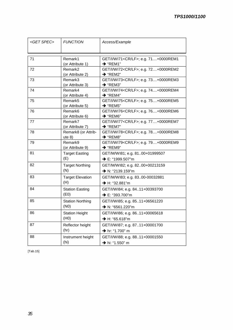
GET Syntax: GET/n/WI<GET SPEC>/<Parameter><CR/LF>
<GET SPEC> FUNCTION Access/Example
11 Pointnumber GET/M/WI11<CR/LF>; e.g. 11… .+00000H66è PtNo=“H66“
12 Serial number GET/I/WI12<CR/LF>; e.g. 12....+00640054è S.No. “640054”
13 Instrument type GET/I/WI13<CR/LF>; 13....+00TCR305è Instr. “TCR305”
19 Time[MM.DD.hh.mm]
GET/I/WI19; e.g. 19....+02081029è “Feb. 8th ; 10:29”
21 Horizontal Angle GET/M/WI21<CR/LF>; e.g. 21.102+17920860è Hz „179.086“ gon
22 Vertical Angle GET/M/WI22<CR/LF>; e.g. 22.102+07567500è V: „75.675“ gon
31 Slope distance GET/M/WI31<CR/LF>; e-g. 31..00+00003387è Sdist: „3.387“ m
32 Horizontal distance GET/M/WI32<CR/LF>; e.g. 32..00+00003198è Hdist: „3.198“ m
33 Height difference GET/M/WI33<CR/LF>; e.g. 33..00+00001119è Hdiff: „1.119“ m
41 Code-Block ID GET/I/WI41<CR/LF>; e.g. 41....+00000013è Code: „13“ m
42 Information 1 GET/I/WI42<CR/LF>; e.g. 42....+000TREESè Info1: „TREES“
43 Information 2 GET/I/WI43<CR/LF>; e.g. 43....+000004.5è Info2: „4.5“
44 Information 3 GET/I/WI44<CR/LF>; e.g. 44....+00CAT.02è Info3: „CAT.02“
45 Information 4 GET/I/WI45<CR/LF>; e.g. 45....+000000NNè Info4: „NN“
46 Information 5 GET/I/WI46<CR/LF>; e.g. 46....+000000NNè Info5: „NN“
47 Information 6 GET/I/WI47<CR/LF>; e.g. 47....+000000NNè Info6: „NN“
48 Information 7 GET/I/WI48<CR/LF>; e.g. 48....+000000NNè Info7: „NN“
49 Information 8 GET/I/WI49<CR/LF>; e.g. 49....+000000NNè Info8: „NN“
51 PPM/mm GET/I/WI51<CR/LF>; e.g. 51..1.+0000+034è “0”ppm; “34”mm
58 Prism constant GET/I/WI58; e.g. 58..16+00000020è Prism „2“ mm
59 PPM GET/I/WI59; e.g. 59..16+02200000è PPM „220“
[… cont.]
TPS1000/1100
35
<GET SPEC> FUNCTION Access/Example
71 Remark1(or Attribute 1)
GET/I/WI71<CR/LF>; e.g. 71....+0000REM1è “REM1”
72 Remark2(or Attribute 2)
GET/I/WI72<CR/LF>; e.g. 72....+0000REM2è “REM2”
73 Remark3(or Attribute 3)
GET/I/WI73<CR/LF>; e.g. 73....+0000REM3è “REM3”
74 Remark4(or Attribute 4)
GET/I/WI74<CR/LF>; e.g. 74....+0000REM4è “REM4”
75 Remark5(or Attribute 5)
GET/I/WI75<CR/LF>; e.g. 75....+0000REM5è “REM5”
76 Remark6(or Attribute 6)
GET/I/WI76<CR/LF>; e.g. 76....+0000REM6è “REM6”
77 Remark7(or Attribute 7)
GET/I/WI77<CR/LF>; e.g. 77....+0000REM7è “REM7”
78 Remark8 (or Attrib-ute 8)
GET/I/WI78<CR/LF>; e.g. 78....+0000REM8è “REM8”
79 Remark9(or Attribute 9)
GET/I/WI79<CR/LF>; e.g. 79....+0000REM9è “REM9”
81 Target Easting(E)
GET/M/WI81; e.g. 81..00+01999507è E: “1999.507”m
82 Target Northing(N)
GET/M/WI82; e.g. 82..00+00213159è N: “2139.159”m
83 Target Elevation(H)
GET/M/WI83; e.g. 83..00-00032881è H: “32.881”m
84 Station Easting(E0)
GET/I/WI84; e.g. 84..11+00393700è E: “393.700”m
85 Station Northing(N0)
GET/I/WI85; e.g. 85..11+06561220è N: “6561.220”m
86 Station Height(H0)
GET/I/WI86; e.g. 86..11+00065618è H: “65.618”m
87 Reflector height(hr)
GET/I/WI87; e.g. 87..11+00001700è hr: “1.700” m
88 Instrument height(hi)
GET/I/WI88; e.g. 88..11+00001550è hi: “1.550” m
[Tab.15]

TPS1000/1100
36
Telescope positioning (TM, TCM and TCA models only)
Command FunctionPASSWORD Allows the use of the following commands. It must
be sent at least once after the instrument isswitched on
CFACE Turns the telescope to the opposite facePOSIT/<spec>Hz/V Turns the telescope to the given direction horizon-
tally and vertically. Hz and V are given in the unit setin the instruments
List of <spec>A Absout positioning to the giben valuesR Relative positioning from the current positionP Turn the telescope to the direction of the last dis-
tance measurementS Search for a reflector in the giben range from the
Current positon (only valid for TCA)
Example:POSIT/A/123.4567/99.8754 Turns the telescope to the circle reading 123.4567
gon Hz and 99.8754 gon Vertical.POSIT/R/20/0 Turns the telescope 20 units clockwise.POSIT/P/1/-1 Tuns to the last position where a distance has been
measured with 1 gon offset horizontal and vertical.POSIT/S/2/2 Searches for a reflector in the range of 2 gons Hori-
zontal and vertical.

TPS1000/1100
37
Warnings/Errors
Errors, initiated by an interface command are not always transferred to the interface. Instead of theerror message the warning @W127 will be sent and the TPS will be ready to receive the next com-mand.
Message ID Meaning Possible reasons
@W100 Instrument busy Any other device is still interfacing the instru-ment; check interfacing priorities
@W127 Invalid command The string sent to the TC could not be decodedproperly or does not exist; check the syntax,or…Input buffer overflow (max. 100 characters)
@E112 Battery low Low Battery; check voltage@E117 Initialization error Contact service@E119 Temperature out of
rangeRefer to manual for temperature range
@E139 EDM error The EDM could not proceed the requestedmeasurement; no or weak signal; Check EDMmode and target
@E144 V or Hz collimationerror
Check calibration data
@E150 Angle error Call service@E158 One of the instruments
sensor correctionscould not be assigned.
Instrument is not stable, not levelled or suffer-ing of vibration; Tilt is out of range (e.g. whentilt sensor is out of range); Level instrument orswitch off compensator
@E182 Telescope positionout of range
Positioning timeout; Instrument could not posi-tion; Try again
@E190 General motorisationError
If frequently occurs call service
@E191 Data error Check record mask@E194 General error If frequently occurs call service@E197 ATR error ATR not enabled; check ATR function
[Tab.16]

Illustrations, descriptions and technical data are not binding and may be changed.
Printed in Switzerland. Copyright Leica Geosystems AG, Heerbrugg, Switzerland, 1999
722 835en – VI.00 – INT
Geosystems