gs200 dc voltage/current source user's manual
TRANSCRIPT

IM GS210-01EN8th Edition
DC Voltage/Current SourceGS200

User RegistrationYOKOGAWA provides registered users with useful information and services. Please allow us to serve you best by completing the user registration form accessible from our website.
https://tmi.yokogawa.com/support/
Contact UsIf you want to resolve a technical support issue or need to contact YOKOGAWA, please fill out the inquiry form on our website.
https://tmi.yokogawa.com/contact/
PIM 103-06E

Thank you for purchasing the GS200 DC voltage/current source.This user’s manual explains the features, operating procedures, and handling precautions of the GS200. To ensure correct use, please read this manual thoroughly before beginning operation. Keep this manual in a safe place for quick reference in the event a question arises.
List of ManualsThe following manuals, including this one, are provided as manuals for the GS200. Please read all manuals.
Manual Title Manual No. DescriptionGS200 DC Voltage/Current Source User’s Manual
IM GS210-01EN This manual. The manual explains the handling precautions, features, specifications, communication interfaces, how to operate the GS200, and so on.
GS200 DC Voltage/Current Source
IM GS210-92Z1 Document for China
Safety Instruction Manual IM 00C01C01-01Z1 Safety manual (European languages)
The “EN” and “Z1” in the manual numbers are the language codes.
Contact information of Yokogawa offices worldwide is provided on the following sheet.
Document No. DescriptionPIM 113-01Z2 List of worldwide contacts
Notes• The contents of this manual are subject to change without prior notice as a result
of continuing improvements to the instrument’s performance and functionality. The figures given in this manual may differ from those that actually appear on your screen.
• Every effort has been made in the preparation of this manual to ensure the accuracy of its contents. However, should you have any questions or find any errors, please contact your nearest YOKOGAWA dealer.
• Copying or reproducing all or any part of the contents of this manual without YOKOGAWA’s permission is strictly prohibited.
• The TCP/IP software of this product and the document concerning the TCP/IP software have been developed/created by YOKOGAWA based on the BSD Networking Software, Release 1 that has been licensed from University of California.
Trademarks• Microsoft, Internet Explorer, MS-DOS, Windows, and Windows XP are either
registered trademarks or trademarks of Microsoft Corporation in the United States and/or other countries.
• Adobe and Acrobat are trademarks of Adobe Systems Incorporated.• In this manual, the ® and TM symbols do not accompany their respective registered
trademark or trademark names.• Other company and product names are registered trademarks or trademarks of their
respective holders.
8th Edition: November 2021 (YMI)All Rights Reserved, Copyright ©2009, Yokogawa Electric CorporationAll Rights Reserved, Copyright ©2012, Yokogawa Test & Measurement Corporation
iIM GS210-01EN

Revisions• 1st Edition : December 2009• 2nd Edition: July 2012• 3rd Edition: September 2013• 4th Edition: March 2016• 5th Edition: October 2017• 6th Edition: August 2019• 7th Edition: March 2021• 8th Edition: November 2021
ii IM GS210-01EN

Checking the Contents of the Package
After receiving the product and opening the package, check the items described below. If the wrong items have been delivered, if items are missing, or if there is a problem with the appearance of the items, contact your nearest YOKOGAWA dealer.
GS200Check that the model name and suffix code given on the name plate on the side panel are the same as those on your order.
Yokogawa Test & Measurement Corporation
Yokogawa Test & Measurement Corporation
MODEL and SUFFIX CodesModel Suffix Code1 DescriptionGS210 DC voltage/current source (front panel output terminals)GS211 DC voltage/current source (rear panel output terminals)Supply voltage -1 100 VAC, 50/60 Hz
-4 120 VAC, 50/60 Hz-7 230 VAC, 50/60 Hz
Power cord2 -D UL/CSA Standard Power Cord (Part No.: A1006WD)[Maximum rated voltage: 125 V; Maximum rated current: 7A]
-F VDE Standard Power Cord (Part No.: A1009WD)[Maximum rated voltage: 250 V; Maximum rated current: 10 A]
-Q BS Standard Power Cord (Part No.: A1054WD)[Maximum rated voltage: 250 V; Maximum rated current: 10 A]
-R AS Standard Power Cord (Part No.: A1024WD)[Maximum rated voltage: 250 V; Maximum rated current: 10 A]
-H GB Standard Power Cord (Part No.: A1064WD)[Maximum rated voltage: 250 V; Maximum rated current: 10 A]
-N Brazilian Standard Power Cord (Part No.: A1088WD)[Maximum rated voltage: 250 V; Maximum rated current: 10 A]
-T Taiwanese Standard Power Cord (Part No.: A1100WD)[Maximum rated voltage: 125 V; Maximum rated current: 10 A]
-B Indian Standard Power Cord (Part No.: A1101WD)[Maximum rated voltage: 250 V; Maximum rated current: 10 A]
-U IEC Plug Type B Power Cord (Part No.: A1102WD)[Maximum rated voltage: 250 V; Maximum rated current: 7 A]
-Y No power cord included.3
Options /MON Voltage and current monitoring/C10 Ethernet interface
1 For products whose suffix code contains “Z,” an exclusive manual may be included. Please read it along with the standard manual.
2 Make sure that the attached power cord meets the designated standards of the country and area that you are using it in.
3 Prepare a power cord that complies with the standard specified by the country or region that the instrument will be used in.
NO. (Instrument Number)When contacting the dealer from which you purchased the instrument, please tell them the instrument number.
iiiIM GS210-01EN

Checking the Contents of the Package
Standard AccessoriesThe standard accessories below are supplied with the instrument.
Name Model or Part No. Quantity NotesPower cord1 See the previous
page1 —
Rubber feet A9088ZM 1 Two rubber feet in one set.Spare power supply fuse
Power cord suffix code-1 or -4 A1109EF 1 250 V, 1 A, time lag.-7 A1108EF 1 250 V, 0.5 A, time lag.
Measurement lead 758933 1 set Safety terminal cable. Red and black, 1 pc each.Only included with the GS210.
Alligator clip adapter 758922 1 set Safety terminal-to-alligator clip adapter. Red and black, 1 pc each.Only included with the GS210.
Terminal plug A2006JT 1 Only included with the GS211.Manuals IM GS210-01EN 1 User’s Manual (this manual).
IM GS210-92Z1 1 Document for China IM 00C01C01-01Z1 1 Safety manual (European languages)PIM 113-01Z2 1 List of worldwide contacts
Standard accessories are not covered by warranty.
D F RQ H
Brazilian StandardA1088WD
Taiwanese StandardA1100WD
Indian StandardA1101WD
IEC plug Type BA1102WD
T UBN
Rubber feetA9088ZM
Manuals• IM GS210-01EN (this manual)• IM GS210-92Z1• IM 00C01C01-01Z1• PIM 113-01Z2
Measurement lead2
758933
Alligator clip adaptor set2
758922
Spare power supply fuseA1109EF or A1108EF
Terminal plug3
A2006JT
UL, CSA StandardA1006WD
VDE StandardA1009WD
BS StandardA1054WD
AS StandardA1024WD
One of these power cords1 is supplied according to the suffix code.
GB StandardA1064WD
1 Make sure that the attached power cord meets the designated standards of the country and area that you are using it in. If the suffix code is -Y, a power cord is not included.
2 Only included with the GS210.3 Only included with the GS211.
iv IM GS210-01EN

Checking the Contents of the Package
Optional Accessories (Sold separately)The optional accessories below are available for purchase separately.
Name Model/ Part No.
Min. Q’ty Notes Manual No.
Measurement lead 758917 1 set Safety terminal cable with 2 leads (red and black) in a set. Length: 0.75 m. Rating: 1000 V, 32 A.
—
758933 1 set Safety terminal cable with 2 leads (red and black) in a set. Length: 1 m. Rating: 1000 V, 19 A.
—
Alligator clip adapter (small)
758922 1 set Safety terminal-to-alligator clip adapter. Red and black, 1 pc each. Rating: 300 V, 15 A.
—
Alligator clip adapter (large)
758929 1 set Safety terminal-to-alligator clip adapter. Red and black, 1 pc each. Rating: 1000 V, 32 A.
—
Fork terminal adapter 758921 1 set Safety terminal-to-fork terminal adapter. Red and black, 1 pc each. Rating: 1000 V, 20 A
—
Conversion adapter 758924 1 Safety BNC-to- banana adapter. Rating: 500 V. —BNC cable 366924 1 BNC-BNC. Length: 1 m. Rating: 42 V. —
366925 1 BNC-BNC. Length: 2 m. Rating: 42 V. —Safety terminal adapter 758923 1 set Spring clamp type. Red and black, 1 pc. each.
Rating: 600 V, 10 A—
758931 1 set Screw-in type. Red and black, 1 pc. each.Rating: 1000 V, 36 A
—
Terminal plug A2006JT 1 For use with the GS211 rear panel terminals. —Synchronous operation cable
758960 1 RJ-11 cable, 6 pins. Length: 1 m —
Accessories (sold separately) are not covered by warranty.
WARNING• Use the accessories specified in this manual. Moreover, use the accessories of
this product only with Yokogawa products that specify them as accessories.• Use the accessories of this product within the rated range of each accessory.
When using several accessories together, use them within the specification range of the accessory with the lowest rating.
• Due to the structure of the product, it is possible to touch the metal parts of the fork terminal adapter 758921. Be careful as this constitutes an electric shock hazard.
CAUTIONUse BNC cables 366924 and 366925 for the BNC I/O terminals.
French
AVERTISSEMENT• Utiliser les accessoires spécifiés dans ce manuel. En outre, utiliser les
accessoires de ce produit uniquement avec des produits Yokogawa pour lesquels ils sont spécifiés comme accessoires.
• Utilisez les accessoires de ce produit en fonction des valeurs nominales de chacun. Lorsque vous employez plusieurs accessoires en même temps, utilisez les valeurs de l’accessoire ayant les valeurs nominales les plus faibles.
• Compte tenu de la structure du produit, il est possible de toucher les pièces métalliques de l’adaptateur de borne à fourche 758921. Procédez avec soin, car cette opération présente un risque de choc électrique.
vIM GS210-01EN

Checking the Contents of the Package
ATTENTIONUtiliser les câbles BNC 366924 et 366925 pour les bornes E/S BNC.
vi IM GS210-01EN

Safety Precautions
This product is designed to be used by a person with specialized knowledge.This instrument is an IEC safety class I instrument (provided with a terminal for protective earth grounding). The general safety precautions described herein must be observed during all phases of operation. If the instrument is used in a manner not specified in this manual, the protection provided by the instrument may be impaired. This manual is part of the product and contains important information. Store this manual in a safe place close to the instrument so that you can refer to it immediately. Keep this manual until you dispose of the instrument. YOKOGAWA assumes no liability for the customer’s failure to comply with these requirements.
The following symbols are used on this instrument. Warning: handle with care. Refer to the user’s manual or service manual.
This symbol appears on dangerous locations on the instrument which require special instructions for proper handling or use. The same symbol appears in the corresponding place in the manual to identify those instructions.
Ground (earth) or functional ground terminal (do not use this terminal as a protective ground terminal).
Alternating current
ON (power)
OFF (power)
In-position of a bi-stable push control
Out-position of a bi-stable push control
French
Avertissement : À manipuler délicatement. Toujours se reporter aux manuels d’utilisation et d’entretien. Ce symbole a été apposé aux endroits dangereux de l’instrument pour lesquels des consignes spéciales d’utilisation ou de manipulation ont été émises. Le même symbole apparaît à l’endroit correspondant du manuel pour identifier les consignes qui s’y rapportent.
Borne de terre ou borne de terre fonctionnelle (ne pas utiliser cette borne comme prise de terre.)
Courant alternatif
Marche (alimentation)
Arrêt (alimentation)
Marche
Veille
viiIM GS210-01EN
Safety Precautions
Failure to comply with the precautions below could lead to injury or death or damage to the instrument.
WARNINGUse the Instrument Only for Its Intended PurposeThe GS200 is a generator that can generate DC voltage and current. Do not use this instrument for anything other than as a DC voltage and current generator.
Check the Physical AppearanceDo not use the instrument if there is a problem with its physical appearance.
Use the Correct Power SupplyMake sure that the power supply voltage matches the instrument’s rated supply voltage and that it does not exceed the maximum voltage range of the power cord to use.
Use the Correct Power Cord and PlugTo prevent the possibility of electric shock or fire, be sure to use the power cord for the instrument. The main power plug must be plugged into an outlet with a protective earth terminal. Do not disable this protection by using an extension cord without protective earth grounding. Further, do not use this power cord with other instruments.Do not use the power cord in a bundled condition. If you use a power plug with foreign substance on it, insulation may be compromised by humidity or other factors and may cause a fire. Clean the power plug regularly.
Connect the Protective Grounding TerminalBe sure to connect the protective earth to prevent electric shock before turning ON the power. The power cord that you can use for the instrument is a three-prong cord. Connect the power cord to a properly grounded three-prong outlet.
Do Not Impair the Protective GroundingNever cut off the internal or external protective earth wire or disconnect the wiring of the protective earth terminal. Doing so poses a potential shock hazard.
Do Not Use When the Protection Functions Are DefectiveBefore using this instrument, check that the protection functions, such as the protective grounding and fuse, are working properly. If you suspect a defect, do not use the instrument.
Do Not Operate in an Explosive AtmosphereDo not operate the instrument in the presence of flammable gasses or vapors. Operation in such an environment constitutes a safety hazard.
Do Not Remove the Covers or Disassemble or Alter the InstrumentOnly qualified YOKOGAWA personnel may remove the covers and disassemble or alter the instrument. The inside of the instrument is dangerous because parts of it have high voltages.
Ground the Instrument before Making External ConnectionsSecurely connect the protective grounding before connecting to the item under measurement or to an external control unit. Before touching the target device, turn off this instrument and check that there is no voltage or current being output.
viii IM GS210-01EN

Safety Precautions
Measurement CategoryThe measurement category of the GS200 signal input terminals is Other (O). Do not use it to measure the main power supply or for Measurement Categories II, III, and IV.
Installation Location• This instrument is designed to be used indoors. Do not install or use it outdoors.• Install the instrument so that you can immediately remove the power cord if an
abnormal or dangerous condition occurs.
Using in a Floating Condition• Depending on the connected external device, dangerous voltage may appear
at the terminals if the instrument is used in a floating condition. Be careful of electric shock and electric discharge.
• To prevent electric shock, remove rings, watches, and other metallic accessories and jewelry before operation.
Wiring CorrectlyDangerous voltage may appear at the terminals if the instrument is used in a floating condition. If you do not connect the devices correctly, not only will it damage the instrument or the target device, it may also lead to electric shock or fire. Be careful when you connect the lead wires, and be sure to check the following points.• When using the instrument in a floating condition, make sure that the electric
potential of each output terminal is within ±250 Vpeak relative to the ground.
Before output (before turning on the output), check that:• Lead wires are connected to the instrument’s output terminals correctly.• Lead wires are connected to the target device correctly.
During output, check that:• Never touch the terminals and the connected lead wires when the item under
measurement is on.
CAUTIONOperating Environment LimitationsThis product is classified as Class A (for use in industrial environments). Operation of this product in a residential area may cause radio interference, in which case the user will be required to correct the interference.
ixIM GS210-01EN

French
AVERTISSEMENTUtiliser l’instrument aux seules fins pour lesquelles il est prévuGS200 est un générateur qui peut générer une tension et un courant CC. Ne pas utiliser l’instrument à d’autres fins que celles prévues.
Inspecter l’apparence physiqueNe pas utiliser l’instrument si son intégrité physique semble être compromise.
Vérifier l’alimentationAssurez-vous que la tension d’alimentation correspond à la tension d’alimentation nominale de l’appareil et qu’elle ne dépasse pas la plage de tension maximale du cordon d’alimentation à utiliser.
Utiliser le cordon d’alimentation et la fiche adaptésPour éviter tout risque de choc électrique, utiliser exclusivement le cordon d’alimentation prévu pour cet instrument. La fiche doit être branchée sur une prise secteur raccordée à la terre. En cas d’utilisation d’une rallonge, celle-ci doit être impérativement reliée à la terre. Par ailleurs, ne pas utiliser ce cordon d’alimentation avec d’autres instruments.N’utilisez pas le cordon d’alimentation en faisceau. Si vous utilisez un cordon d’alimentation sur lequel se trouve une substance étrangère, l’isolation risque d’être compromise par l’humidité ou d’autres facteurs, ce qui peut provoquer un incendie. Nettoyez la fiche du cordon d’alimentation régulièrement.
Brancher la prise de terreAvant de mettre l’instrument sous tension, penser à brancher la prise de terre pour éviter tout choc électrique. Le cordon d’alimentation que vous utilisez pour l’instrument est un cordon à trois broches. Brancher le cordon d’alimentation sur une prise de courant à trois plots et mise à la terre.
Ne pas entraver la mise à la terre de protectionNe jamais neutraliser le fil de terre interne ou externe, ni débrancher la borne de mise à la terre. Cela pourrait entraîner un choc électrique ou endommager l’instrument.
Ne pas utiliser lorsque les fonctions de protection sont défectueusesAvant d’utiliser l’instrument, vérifier que les fonctions de protection, telles que le raccordement à la terre et le fusible, fonctionnent correctement. En cas de dysfonctionnement possible, ne pas utiliser l’instrument.
Ne pas utiliser dans un environnement explosifNe pas utiliser l’instrument en présence de gaz ou de vapeurs inflammables. Cela pourrait être extrêmement dangereux.
Ne pas retirer le capot, ni démonter ou modifier l’instrumentSeul le personnel YOKOGAWA qualifié est habilité à retirer le capot et à démonter ou modifier l’instrument. Certains composants à l’intérieur de l’instrument sont à haute tension et par conséquent, représentent un danger.
Relier l’instrument à la terre avant de le brancher sur des connexions externesToujours relier l’instrument à la terre avant de le brancher aux appareils à mesurer ou à une commande externe. Avant de toucher un circuit, mettre l’instrument hors tension et vérifier l’absence de tension. Pour éviter tout risque de choc électrique, brancher la terre de la sonde et du connecteur d’entrée sur la terre de l’appareil à mesurer.
Safety Precautions
x IM GS210-01EN

Catégorie de mesureLa catégorie de mesure des terminaux d’entrée de signal du GS200 est Autre (O). Ne pas l’utiliser pour mesurer l’alimentation électrique, ni pour les catégories de mesure II, III et IV.
Installer et utiliser l’instrument aux emplacements appropriés• Ne pas installer, ni utiliser l’instrument à l’extérieur ou dans des lieux exposés à
la pluie ou à l’eau.• Installer l’instrument de manière à pourvoir immédiatement le débrancher du
secteur en cas de fonctionnement anormal ou dangereux.
Utilisation d’une condition de flottement• Selon le dispositif extérieur raccordé, une tension dangereuse peut survenir sur
les bornes si l’instrument est utilisé en condition de flottement. Faites attention au choc électrique et à la décharge électrique.
• To prevent electric shock, remove rings, watches, and other metallic accessories and jewelry before operation.
Câblage correctUne tension dangereuse peut survenir sur les bornes si l’instrument est utilisé en condition de flottement. Si vous ne raccordez pas correctement les appareils, non seulement cela risque d’endommager l’équipement ou l’appareil cible, mais en plus cela risque d’entraîner un choc électrique ou un incendie. Branchez toujours les câbles en plomb correctement et vérifiez les points suivants.• Lorsque l’instrument est utilisé en condition de flottement, veiller à ce que le
potentiel électrique de chaque borne de sortie soit inférieur à ± 250 V de crête par rapport à la masse.
Avant le sortie (avant la mise sous tension), vérifier que :• Les câbles en plomb sont correctement raccordés aux bornes de sortie de
l’équipement.• Les câbles en plomb sont correctement raccordés à l’appareil cible.
Pendant la sortie, vérifier que :• Ne jamais toucher les bornes et les câbles branchés lorsque l’appareil à
mesurer est sous tension.
ATTENTIONLimitations relatives à l’environnement opérationnelCe produit est classé dans classe A (pour utilisation dans des environnements industriels). L’utilisation de ce produit dans un zone résidentielle peut entraîner une interférence radio que l’utilisateur sera tenu de rectifier.
Safety Precautions
xiIM GS210-01EN

Regulations and Sales in Various Countries and Regions
Waste Electrical and Electronic Equipment (WEEE)
(EU WEEE Directive valid only in the EEA* and UK WEEE Regulation in the UK) This product complies with the WEEE marking requirement. This marking
indicates that you must not discard this electrical/electronic product in domestic household waste. When disposing of products in the EEA or UK, contact your local Yokogawa office in the EEA or UK respectively.
* EEA: European Economic Area
Batteries and Waste Batteries
(EU Battery Directive/Regulation valid only in the EEA and UK Battery Regulation in the UK)
Batteries are included in this product. This marking indicates they shall be sorted out and collected as ordained in the EU battery Directive/Regulation and UK battery Regulation.
Battery type: Lithium battery When you need to replace batteries, contact your local Yokogawa office in the
EEA or UK respectively.
Authorized Representative in the EEAYokogawa Europe B.V. is the authorized representative of Yokogawa Test & Measurement Corporation for this product in the EEA. To contact Yokogawa Europe B.V., see the separate list of worldwide contacts, PIM 113-01Z2.
關於在台灣銷售This section is valid only in Taiwan.關於在台灣所販賣的符合其相關規定的電源線A1100WD的限用物質含量信息,請至下麵
的網址進行查詢
https://tmi.yokogawa.com/support/service-warranty-quality/product-compliance/
DisposalWhen disposing of YOKOGWA products, follow the laws and ordinances of the country or region where the product will be disposed of.
xii IM GS210-01EN
Symbols and Notations Used in This Manual
Safety MarkingsThe following markings are used in this manual.
Improper handling or use can lead to injury to the user or damage to the instrument. This symbol appears on the instrument to indicate that the user must refer to the user’s manual for special instructions. The same symbol appears in the corresponding place in the user’s manual to identify those instructions. In the manual, the symbol is used in conjunction with the word “WARNING” or “CAUTION.”
WARNING Calls attention to actions or conditions that could cause serious or fatal injury to the user, and precautions that can be taken to prevent such occurrences.
French
AVERTISSEMENT Attire l’attention sur des gestes ou des conditions susceptibles de provoquer des blessures graves (voire mortelles), et sur les précautions de sécurité pouvant prévenir de tels accidents.
CAUTION Calls attention to actions or conditions that could cause light injury to the user or damage to the instrument or user’s data, and precautions that can be taken to prevent such occurrences.
French
ATTENTION Attire l’attention sur des gestes ou des conditions susceptibles deprovoquer des blessures légères ou d’endommager l’instrument ou lesdonnées de l’utilisateur, et sur les précautions de sécurité susceptiblesde prévenir de tels accidents.
Note Calls attention to information that is important for proper operation of the instrument.
xiiiIM GS210-01EN
Notations Used in the Procedural ExplanationsOn pages that describe the operating procedures in chapters 3 through 15 and the appendix, the following symbols are used to distinguish the procedures from their explanations.
Procedure Carry out the procedure according to the step numbers. All procedures are written under the assumption that you are starting operation at the beginning of the procedure, so you may not need to carry out all the steps in a procedure when you are changing the settings.
Explanation This section describes the setup items and the limitations regarding the procedures. It may not give a detailed explanation of the feature. For a detailed explanation of the feature, see chapter 2.
<<Corresponding Command Mnemonic>>Indicates a communication command that corresponds to the feature described on the procedural explanation page.
Characters and Terminology Used in Procedural ExplanationsKeysBold characters used in the procedural explanations indicate characters that are marked on the panel keys.
NUM LOCK + or This means the following: press the NUM LOCK key to make it illuminate, and then press the or key. When the instrument is in this state, you can use the and keys to directly access the items that are marked above and below these keys (numbers 0 to 9, period, and BS).
Symbols and Notations Used in This Manual
xiv IM GS210-01EN

Contents
List of Manuals ...................................................................................................................................iChecking the Contents of the Package............................................................................................ iiiSafety Precautions .......................................................................................................................... viiRegulations and Sales in Various Countries and Regions .............................................................. xiiSymbols and Notations Used in This Manual ................................................................................ xiii
Chapter 1 Component Names and Functions1.1 Front Panel ....................................................................................................................... 1-11.2 Rear Panel ....................................................................................................................... 1-21.3 Display Mode and Displayed Contents ............................................................................ 1-31.4 Keys ................................................................................................................................. 1-5
Chapter 2 Features2.1 SystemConfiguration ....................................................................................................... 2-1
ProductFeaturesandSystemConfiguration ................................................................ 2-12.2 Source Feature and Measurement Feature (Monitoring feature; /MON option) ............... 2-3
2.3 Source .............................................................................................................................. 2-6Source Range ............................................................................................................... 2-6Source Function ............................................................................................................ 2-7Source Action ................................................................................................................ 2-7Output ON/OFF ............................................................................................................. 2-8DUT Protection Using Limiters ...................................................................................... 2-8Local Sense and Remote Sense ............................................................................... 2-10Guard Terminal Feature .............................................................................................. 2-10
2.4 Programs .........................................................................................................................2-11Program Feature ..........................................................................................................2-11Program Interval Time ..................................................................................................2-11Program Slope Time ....................................................................................................2-11Repeating Programs ................................................................................................... 2-12Program Triggers ........................................................................................................ 2-12Program Files .............................................................................................................. 2-13Executing Programs .................................................................................................... 2-14
2.5 Measurement (Monitoring feature; /MON option) ........................................................... 2-16Measurement Function and Measurement Range ...................................................... 2-16Measurement ON/OFF ............................................................................................... 2-16Measurement Operation ............................................................................................. 2-16Measurement Delay .................................................................................................... 2-17Highly Accurate Measurement and High-Speed Measurement .................................. 2-17NULL Computation ...................................................................................................... 2-17Store/Recall (Statistical Computation Value Display).................................................. 2-18
2.6 Triggering ....................................................................................................................... 2-20Overview ..................................................................................................................... 2-20Program Triggers ........................................................................................................ 2-20Measurement Triggers (/MON option) ....................................................................... 2-21Trigger Block Diagram ................................................................................................ 2-22Trigger Output ............................................................................................................. 2-23Trigger Hold ................................................................................................................ 2-23Sampling Error ............................................................................................................ 2-23
3
2
1
4
5
6
7
8
9
10
11
12
13
14
15
App
Index
xvIM GS210-01EN
2.7 Synchronization .............................................................................................................. 2-24Synchronization .......................................................................................................... 2-24External I/O ................................................................................................................. 2-24
2.8 Other Features ............................................................................................................... 2-25USB Storage Feature .................................................................................................. 2-25USB Communication (USB-TMC command control) .................................................. 2-26Ethernet Communications (/C10 option) ..................................................................... 2-27GP-IB Communications .............................................................................................. 2-27Saving, Loading, and Deleting Setup Data ................................................................. 2-27Selecting the Settings Applied at Power-On ............................................................... 2-27
Chapter 3 Instrument Preparation and Common Operations3.1 Handling Precautions ....................................................................................................... 3-1
3.2 Installation ........................................................................................................................ 3-3 3.3 Connecting the Power Supply .......................................................................................... 3-73.4 TurningthePowerSwitchOnandOff .............................................................................. 3-9
3.5 Wiring Precautions ..........................................................................................................3-113.6 Wiring the GS211 Rear Panel Terminal Plug .................................................................. 3-143.7 SettingtheDate,Time,andtheTimeDifferencefromGMT(GreenwichMeanTime) ... 3-15
Chapter 4 Common Settings4.1 Basic Key Operations and How to Enter Values .............................................................. 4-1
4.2 Selecting the Wiring System (Remote Sense or Local Sense) ........................................ 4-34.3 Setting the Guard Terminal ............................................................................................... 4-54.4 USB Storage Feature ....................................................................................................... 4-7
Chapter 5 Source5.1 Setting the Source Function ............................................................................................. 5-15.2 Setting the Source Range ................................................................................................ 5-25.3 Setting the Source Level .................................................................................................. 5-35.4 Setting the Limiter ............................................................................................................ 5-45.5 TurningtheOutputOnandOff ......................................................................................... 5-5
Chapter 6 Programs6.1 TurningProgramRepetitionModeOnandOff ................................................................. 6-16.2 Setting the Program Interval Time .................................................................................... 6-26.3 Setting the Program Slope Time ...................................................................................... 6-36.4 Setting the Program Trigger (/MON option) ...................................................................... 6-46.5 Creating and Editing Programs ........................................................................................ 6-56.6 Saving and Loading Programs ......................................................................................... 6-86.7 Executing Programs ....................................................................................................... 6-12
Chapter 7 Measurement (Option)7.1 TurningMeasurementOnandOff .................................................................................... 7-17.2 Setting the Integration Time ............................................................................................. 7-27.3 Setting the Measurement Delay ....................................................................................... 7-37.4 Selecting the Measurement Trigger ................................................................................. 7-47.5 Setting the Measurement Timer ....................................................................................... 7-57.6 TurningtheNULLComputationOnandOff ..................................................................... 7-67.7 Zero Calibration (Zero reference measurement) .............................................................. 7-77.8 Storing Measured Results ................................................................................................ 7-87.9 Performing Statistical Computations on Measured Values (Recall) ............................... 7-10
Contents
xvi IM GS210-01EN
Contents
Chapter 8 Synchronous Operation 8.1 Synchronous Operation Using the BNC I/O Terminals (IN and OUT) .............................. 8-18.2 Using the RJ-11 Connectors (SYNC IN and SYNC OUT) to Perform Synchronous
Operation .......................................................................................................................... 8-5
Chapter 9 Other Features9.1 Initializing Setup Data ....................................................................................................... 9-19.2 Saving, Loading, and Deleting Setup Data ...................................................................... 9-29.3 Selecting the Settings Applied at Power-On ..................................................................... 9-49.4 SelectingtheDisplayBrightness,TurningtheDisplayOff,andTurningtheBeepSoundOn
andOff .............................................................................................................................. 9-59.5 Selecting the CSV File Format ......................................................................................... 9-69.6 Error Log Display .............................................................................................................. 9-7
Chapter 10 USB Interface10.1 USBInterfaceFeaturesandSpecifications .................................................................... 10-110.2 Setting the USB Interface Mode ..................................................................................... 10-210.3 Viewing the VISA Setup Information............................................................................... 10-3
Chapter 11 Ethernet Interface (Option)11.1 EthernetInterfaceFeaturesandSpecifications ..............................................................11-111.2 Connecting to a Network .................................................................................................11-211.3 ConfiguringNetworkSettings(TCP/IP) ...........................................................................11-311.4 Viewing the Network Settings ..........................................................................................11-611.5 Web Server Feature ........................................................................................................11-7
Chapter 12 GP-IB Interface12.1 GP-IBInterfaceFeaturesandSpecifications ................................................................. 12-112.2 Connecting the GP-IB Cable .......................................................................................... 12-212.3 Setting the GP-IB Address and Command Mode ........................................................... 12-312.4 7651-Compatible Mode .................................................................................................. 12-412.5 Responses to Interface Messages ................................................................................. 12-512.6 About the IEEE 488.2-1992 Standard ............................................................................ 12-7
Chapter 13 Communication Commands13.1 Program Format ............................................................................................................. 13-1
13.1.1 Symbols Used in the Syntax ............................................................................ 13-113.1.2 Messages ........................................................................................................ 13-113.1.3 Commands ...................................................................................................... 13-313.1.4 Responses ....................................................................................................... 13-513.1.5 Data ................................................................................................................. 13-5
13.2 Commands ..................................................................................................................... 13-713.2.1 List of Commands ............................................................................................ 13-713.2.2 Output Commands (OUTPut group) .............................................................. 13-1013.2.3 Source Commands (SOURce group) .............................................................13-1113.2.4 Program Commands (PROGram group) ....................................................... 13-1313.2.5 Measurement Commands (SENSe group) .................................................... 13-1513.2.6 Measured Value Read Commands (INITiate, FETCh, READ, and MEASure
groups)........................................................................................................... 13-1713.2.7 Store/Recall Commands (TRACe group) ...................................................... 13-1813.2.8 External I/O Commands (ROUTe group) ....................................................... 13-2013.2.9 System Commands (SYSTem group) ............................................................ 13-21
3
2
1
4
5
6
7
8
9
10
11
12
13
14
15
App
Index
xviiIM GS210-01EN
13.2.10 Status Commands (STATus group) ............................................................... 13-2313.2.11 Common Commands ..................................................................................... 13-24
13.3 Status Reports .............................................................................................................. 13-2613.3.1 Status Reports ............................................................................................... 13-2613.3.2 Status Byte .................................................................................................... 13-2813.3.3 Standard Event Register................................................................................ 13-2913.3.4 Extended Event Register ............................................................................... 13-3013.3.5 Output Queue and Error Queue .................................................................... 13-31
Chapter 14 Troubleshooting and Maintenance14.1 Troubleshooting .............................................................................................................. 14-114.2 Error Code Descriptions and Corrective Actions ............................................................ 14-314.3 Self-Test ......................................................................................................................... 14-614.4 Viewing the Product Information..................................................................................... 14-814.5 Updating the System Firmware ...................................................................................... 14-9
14.6 Changing the Power Fuse .............................................................................................14-1114.7 Recommended Replacement Parts and Maintenance ................................................. 14-13
Chapter 15 Specifications15.1 Source Section ............................................................................................................... 15-115.2 Measurement Section (On models with the /MON option) ............................................. 15-315.3 Features ......................................................................................................................... 15-315.4 External I/O Section (BNC (IN/OUT) and I/O for synchronous operation (SYNC IN/OUT)) ...
15-415.5 Interface ......................................................................................................................... 15-515.6 GeneralSpecifications ................................................................................................... 15-615.7 External Dimensions ...................................................................................................... 15-8
AppendixAppendix 1 Factory Default Settings .....................................................................................App-1Appendix 2 Block Diagram ....................................................................................................App-2
Index
Contents
xviii IM GS210-01EN
3
2
1
4
5
6
7
8
9
10
11
12
13
14
15
App
Index
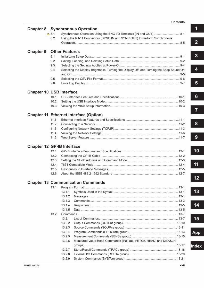
1.1 Front Panel
GS200 DC VOLTAGE/CURRENT SOURCE
SAMPLE ERROR
REPEAT
STORE
REMOTE
ERROR
LOCAL
ESC
POWER NUM LOCK
1 2 3 4 5 BS RANGE
6 7 8 9 0
UTILITY SETUP LIMIT MEASURE
PROGRAM END
DEL
HOLD
STEP
RUN
PROGRAM
OUTPUT
V
mV
mA
SRQ
ENTER
SENSE OUTPUT
32V MAX
0.5V MAX
32V 200mA MAX
Hi
Lo
42V 10mA PEAK
G
G TERM 250 V PEAK TO
Power switch → Section 3.4
Handle Used to carry the GS200. → Section 3.2
Output terminals (only on the GS210)Used to connect the included measurement leads.→ Sections 3.5, 4.2, and 4.3
Soft keys, and keys, and the keypad• Use the soft keys to select items on the soft key menus that appear during configuration.• Use the and keys to increase and decrease each digit of the displayed value during
numeric input.• Use the keypad to specify a value directly during numeric input.→ Section 4.1
ESC (LOCAL) keySwitches the display or clears a soft key menu → Section 4.1
Setup and execution keys These keys are used to change settings or execute operations. Press a setup key to show the respective setup item. → Sections 1.4 and 4.1
Remote indicatorIlluminates when the GS200 is in remote mode (controlled through communications) → Section 12.1
Store indicator Illuminates when store mode is turned on → Section 7.8
Sampling error indicatorIlluminates when a sampling error occurs in a program or measurement trigger → Sections 6.4 and 7.4
Repeat indicatorIlluminates when the program’s repeat mode is turned on → Section 6.1
Output control keyPress to turn the source on and off. → Section 5.5
Error indicatorIlluminates when there are errors in the error log → Section 14.2
1-1IM GS210-01EN
Com
ponent Nam
es and Functions
Chapter 1 Component Names and Functions

1.2 Rear Panel
LINK ACT
ETHERNET 100BASE-TX
IN OUT USB
SYNC
IN OUT
100V AC 80 VA MAX 50/60 Hz FUSE 250 V T 1A
GP-IB (IEEE 488)
Cooling fan → Section 3.2
USB portUsed to connect the GS200 to a PC that has a USB interface and to access the GS200 as USB storage or to control the GS200 through USB-TMC commands.→ Sections 4.4 and 10.2
I/O terminals for synchronous operationUsed to connect multiple GS200s and perform synchronous operation. → Section 8.2
Ethernet portUsed to connect the GS200 to a network. → Section 11.2
BNC I/O terminalsUsed to receive and transmit trigger, output state, and source change completion signals. → Section 8.1
Power inletConnects to a power supply → Section 3.3
GP-IB connector Used when controlling the GS200 with commands through the GP-IB interface. → Section 12.2
Output terminal (only on the GS211)Used to connect the DUT cable. → Sections 3.5, 3.6, 4.2, and 4.3
*
* Only on models with the Ethernet option (/C10).
1-2 IM GS210-01EN

3
2
1
4
5
6
7
8
9
10
11
12
13
14
15
App
Index
1.3 Display Mode and Displayed Contents
Display ModeMain Screen
Limiter indicatorsH: High limiterL: Low limiter
LimitMeasured value1
Source level
Source range
Program execution status
Measurement sample indicator1
1 This is displayed on models with the monitoring (/MON) option.
Menu Screen
Source level
Menu items
Displayed ContentsSource LevelThe source level that is being produced is displayed here.
Measurement Sample Indicator (On models with the /MON option)During measurement, an asterisk illuminates. When the measurement completes, the asterisk turns off. If you are performing sequential measurements that have a short integration time, the asterisk illuminates and turns off once every 100 ms.
Measured Value (On models with the /MON option)When the source function is set to voltage, this displays the measured current. When the source function is set to current, this displays the measured voltage. When there is no measured value, “-------” is displayed. When the source range is set to 10 mV or 100 mV, you cannot use the measurement (monitoring) feature. In these situations, the message “Cannot measure in mV source range” is displayed. When the measurement feature is turned off, “Off” is displayed.On models without the monitoring (/MON) option, nothing is displayed in the measured value area.
1-3IM GS210-01EN
Com
ponent Nam
es and Functions
LimitsWhen the source function is set to voltage, this displays the current limit. When the source function is set to current, this displays the voltage limit. When the source range is set to 10 mV or 100 mV, the limit is fixed to 200 mA (you cannot change this value). In these situations, “------mA” is displayed for the limit.
NoteIn voltage source mode’s 10 mV and 100 mV ranges, the output resistance is approximately 2 Ω. Therefore, these ranges are not suitable when the GS200 is connected to a load that allows current to flow (a low-impedance load). Connect a load that allows as little current to flow as possible (a high-impedance load).
Limiter Indicators• is displayed when the high limiter is activated.• is displayed when the low limiter is activated.
Program Execution StatusWhen a program is running, the following items are displayed.• Steps: The step number that is currently being executed.• Time: The remaining interval time (minutes:seconds.tenths of seconds).
Source RangeThe source range that is currently in use is displayed here.
1-4 IM GS210-01EN
1.3 Display Mode and Displayed Contents
3
2
1
4
5
6
7
8
9
10
11
12
13
14
15
App
Index
1-5IM GS210-01EN
Com
ponent Nam
es and Functions
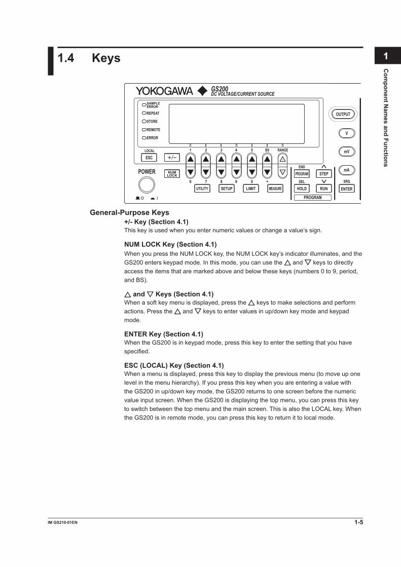
1.4 Keys
GS200 DC VOLTAGE/CURRENT SOURCE
SAMPLE ERROR
REPEAT
STORE
REMOTE
ERROR
LOCAL
ESC
POWER NUM LOCK
1 2 3 4 5 BS RANGE
6 7 8 9 0
UTILITY SETUP LIMIT MEASURE
PROGRAM END
DEL
HOLD
STEP
RUN
PROGRAM
OUTPUT
V
mV
mA
SRQ
ENTER
General-Purpose Keys+/- Key (Section 4.1)This key is used when you enter numeric values or change a value’s sign.
NUM LOCK Key (Section 4.1)When you press the NUM LOCK key, the NUM LOCK key’s indicator illuminates, and the GS200 enters keypad mode. In this mode, you can use the and keys to directly access the items that are marked above and below these keys (numbers 0 to 9, period, and BS).
and Keys (Section 4.1)When a soft key menu is displayed, press the keys to make selections and perform actions. Press the and keys to enter values in up/down key mode and keypad mode.
ENTER Key (Section 4.1)When the GS200 is in keypad mode, press this key to enter the setting that you have specified.
ESC (LOCAL) Key (Section 4.1)When a menu is displayed, press this key to display the previous menu (to move up one level in the menu hierarchy). If you press this key when you are entering a value with the GS200 in up/down key mode, the GS200 returns to one screen before the numeric value input screen. When the GS200 is displaying the top menu, you can press this key to switch between the top menu and the main screen. This is also the LOCAL key. When the GS200 is in remote mode, you can press this key to return it to local mode.

1-6 IM GS210-01EN
Source KeysV Key (Sections 5.2 and 5.3)If you press this key when the GS200 is in up/down key mode and is displaying the main screen, the source function is set to voltage, and the source range is set to 1 V. If you press this key when the GS200 is in keypad mode and is displaying the main screen, the voltage source level that you specified is fixed, the source function is set to voltage, and the source range is set to the most appropriate range greater than or equal to the 1 V range.
mV Key (Sections 5.2 and 5.3)If you press this key when the GS200 is in up/down key mode and is displaying the main screen, the source function is set to voltage, and the source range is set to 10 mV (the circuit that produces the 10 mV range uses the voltage divider). If you press this key when the GS200 is in keypad mode and is displaying the main screen, the voltage source level that you specified is fixed, the source function is set to voltage, and the source range is set to the most appropriate range.
mA Key (Sections 5.2 and 5.3)If you press this key when the GS200 is in upd/down key mode and is displaying the main screen, the source function is set to current and the source range is set to 1 mA. If you press this key when the GS200 is in keypad mode and is displaying the main screen, the current source level that you specified is fixed, the source function is set to current, and the source range is set to the most appropriate range.
RANGE Keys (Section 5.2)Press these keys to change the source range. Press the key to increase the source range by one. Press the key to decrease the source range by one. When a menu is displayed, you can use the key as a menu selection soft key. You cannot change the range continuously by holding these keys down.Depending on the operation menu, these keys may be used to scroll the screen. In these situations, you can scroll the screen by holding these keys down.
LIMIT Key (Section 5.4)Press this key to display the limit input screen. If you press this key in keypad mode when you are entering a limit, the limit that you specified is discarded, and the GS200 returns to the main screen.
OUTPUT Key (Section 5.5)Output turns on and off each time that you press the OUTPUT key. When output is turned on, this key illuminates in red. When output is turned off, this key turns off. When you turn output on, the display switches to the main screen.
1.4 Keys
3
2
1
4
5
6
7
8
9
10
11
12
13
14
15
App
Index
1-7IM GS210-01EN
Com
ponent Nam
es and Functions
Program KeysPROGRAM Key (Chapter 6)Press this key to display the program menu. If you press this key while you are editing a program, program editing finishes.
RUN Key (Section 6.7)Press this key to execute the program from its first step.
STEP Key (Section 6.7)Press this key to execute just one of the program’s steps.
HOLD Key (Section 6.7)Press this key to pause the program that is running. If you press this key while the program execution is paused, the program resumes executing.
If you execute a program by pressing the RUN, STEP, or HOLD key, the display switches to the main screen.
Measurement (Monitoring) Key (Option)MEASURE Key (Chapter 7)Press this key to display the measurement setup menu. On models without the monitoring (/MON) option, if you press the MEASURE key, “Not Available” appears.
Setup Information KeySETUP Key (Sections 9.1, 9.2, and 9.3)Press this key to list setup files and display the SETUP menu.
Communication, System Setup, and Other KeysUTILITY KeyPress this key to display the UTILITY menu. Use the UTILITY menu to access the following settings and features:• Communication settings (section 4.4 and chapters 10, 11, and 12).• Terminal settings (sections 4.2, 4.3, and 8.1).• System settings (sections 3.7, 4.4, and 15.5, and chapter 9).• Self-test (section 15.3).• Product information (section 15.4).• Error log (section 9.6).
1.4 Keys

2.1 System Configuration
Product Features and System Configuration
GS200 Features• The GS200 uses dual D/A conversion to produce voltage and current with high
accuracy and resolution. It can produce stable current or voltage whether it is used for a short or long period of time and maintains superb linearity over all the ranges. You can also use the GS200 to produce voltage and current that has low noise.
• The GS200 can perform four-quadrant operation by operating as a current source or a current sink in the range of ±32 V and ±200 mA.
• The GS200 has an optional voltage and current measurement feature (monitoring feature). The GS200 can measure current in voltage source mode and measure voltage in current source mode. The display resolution is 4½ digits.
• By using the program feature, you can specify up to 10000 steps, each of which controls the generation of voltage or current. You can also generate ramp waveforms by using the slope setting.
• You can use the external I/O BNC connector on the rear panel to control multiple GS200s or other measuring instruments by synchronizing them to actions such as the source action and the output action.
• The I/O terminals for synchronous operation (SYNC IN/OUT) of multiple GS200s can be connected in a daisy chain to allow synchronization of output control and triggers. This increases the number of channels that can be controlled.
• The GS200 has a built-in 4 MB non-volatile storage disk (GS200ROM) for storing various settings and a 16 MB volatile storage disk (GS200RAM) for storing data such as measurement results. If you use USB to connect the GS200 to a PC, you can access these storage disks as the PC’s external drives. Because settings and results are saved to general text files or .CSV files, you can use software such as a text editor or a general-purpose spreadsheet application to edit these files or use them to display graphs on your PC.
In addition to the storage feature, the USB interface can be used to perform command control by way of the USB-TMC protocol. Furthermore, command control can be performed by way of other communication interfaces such as GP-IB, and Ethernet (VXI-11 protocol/7655 command socket).
You can also use the Ethernet interface to access the GS200’s internal disks through FTP (the FTP server feature) and to display the GS200’s information and control it from a Web browser by accessing the GS200 through HTTP (the HTTP server feature).
Chapter 2 Features
2-1IM GS210-01EN
Features
3
2
1
4
5
6
7
8
9
10
11
12
13
14
15
App
Index

System Configuration Diagram
GP-
IB
USB
( USB
-TM
C)
Ethe
r (VX
I-11)
GS200 RAM
GS200 ROM
Internal storage
High
GS200
Low
TRIG OUTPUT
TRIG OUTPUT
Use the USB storage feature to connect the GS200 to a PC as the PC’s external disk.
PC
Command control
Communication line
SYNC OUT
Analog I/O
SYNC IN OUTPUT
High Low SENSE
DUT
BNC OUT BNC IN TRIG OUTPUT
TRIGOUTPUTREADY
READY
Synchronous Operation by Connecting the I/O Terminals for Synchronous Operation (SYNC IN/OUT)
GS200 GS200 GS200
SYNC IN OUT
SYNC IN OUT
SYNC IN OUT
2.1 System Configuration
2-2 IM GS210-01EN

2.2 Source Feature and Measurement Feature (Monitoring feature; /MON option)
This section explains the basic features of the GS200: the source feature and the measurement feature (monitoring feature).
Generating Voltage and CurrentThe GS200 uses dual D/A conversion and a highly accurate power amplifier. This enables you to set the voltage and current at a resolution of 5½ digits.
Voltage SourceThe GS200 has 10 mV, 100 mV, 1 V, 10 V, and 30 V ranges. You can specify and generate a positive or negative voltage of up to 32 V.Current SourceThe GS200 has 1 mA, 10 mA, 100 mA, and 200 mA ranges. You can specify and generate a positive or negative current of up to 200 mA.
The 1 V, 10 V, and 30 V voltage source ranges enable you to generate a positive or negative output current of up to 200 mA with a low output resistance. These ranges are well-suited to situations such as the evaluation of devices that require current.When you select the 10 mV or 100 mV range, the GS200 uses a voltage divider that consists of a pair of resistors. This enables you to use the GS200 to generate low voltages at resolutions as low as 100 nV or as a 3 μVp-p*, low-noise voltage signal source. These ranges are well-suited to providing simulated signals to instruments such as sensors.In current source mode, you can generate a positive or negative output voltage of 30 V on all of the current ranges. Current source mode is well-suited to evaluating the charge/discharge characteristics of rechargeable batteries and other devices.
* 10 mV range, DC to 10 Hz
+
−
+−
1n
+ V, mA V, mA
mV mV
V, mV
mA
Voltage divider
Power amplifierDual D/A converter
Hi
Lo
Shunt resistor
Most significant bits D/A
Least significantbits D/A
2-3IM GS210-01EN
Features
3
2
1
4
5
6
7
8
9
10
11
12
13
14
15
App
Index

Source and Sink OperationsThe GS200 can perform four-quadrant operation by operating as a current source or a current sink in the range of ±32 V and ±200 mA.During sink operation, the GS200 operates in the same quadrants as it does during source operation, so you can use it not just as a true constant voltage source but also as a highly accurate electronic load.
Voltage ranges: 1 V, 10 V, and 30 VMaximum output current: ±200 mA (at 1 V, 10 V, and 30 V ranges)
Current ranges: 1 mA, 10 mA, 100 mA, and 200 mAMaximum output voltage: ±30 V
Voltage and Current Generation Region
200 mA
–32 V 32 V
–200 mA
Current
Voltage
Source Sink
SinkSource
Voltage source
GS200
Load
Source Operation Example
I
Current source
GS200
Battery
Sink Operation Example
I
Bipolar OutputBecause the GS200 inverts the signal polarity and produces the signal without the use of a mechanical contact, no abnormal voltage (or current) is generated when the polarity is inverted. Therefore, the GS200 can generate continuous, variable output ranging from the maximum negative value to the maximum positive value. This is effective when you want to invert the polarity to generate program output or evaluate zero-crossing comparators. Additionally, when you change settings within the same range, glitches are not generated.
2.2 Source Feature and Measurement Feature (Monitoring feature; /MON option)
2-4 IM GS210-01EN
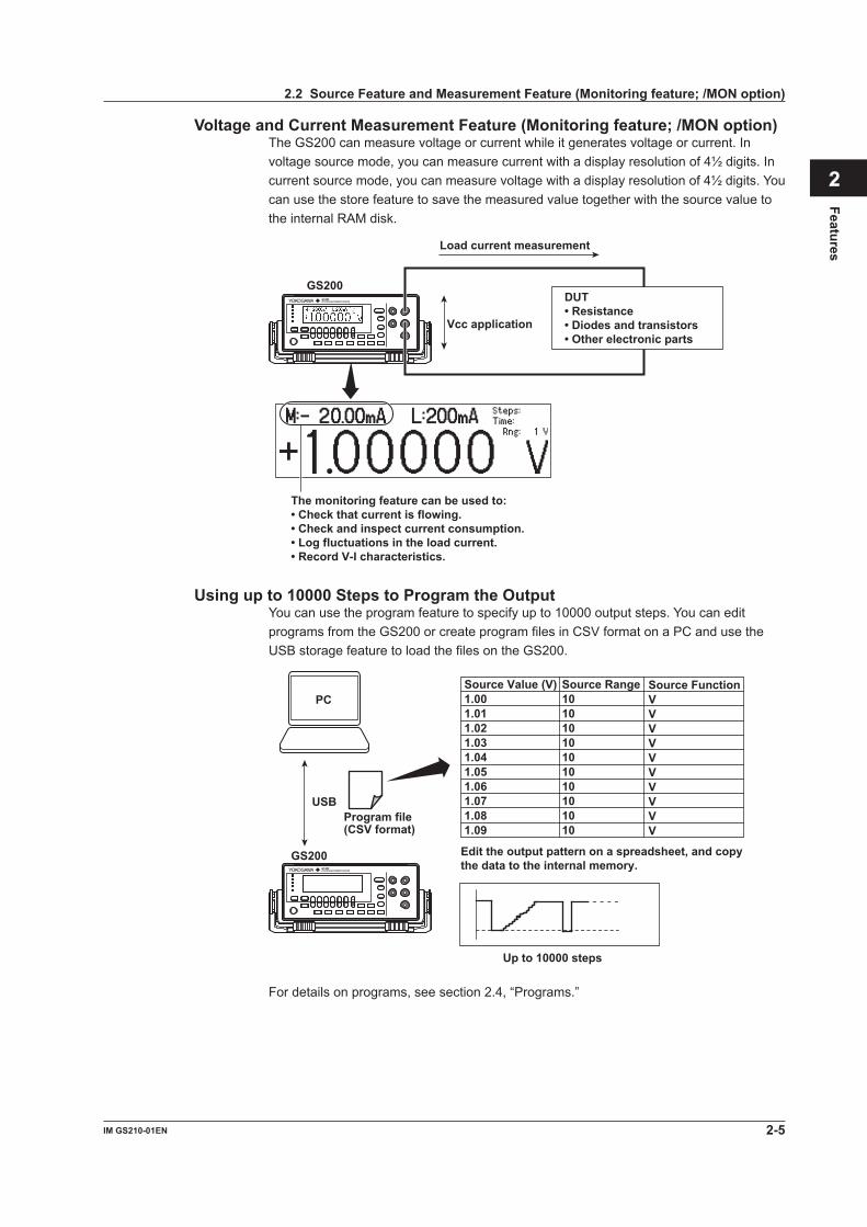
Voltage and Current Measurement Feature (Monitoring feature; /MON option)The GS200 can measure voltage or current while it generates voltage or current. In voltage source mode, you can measure current with a display resolution of 4½ digits. In current source mode, you can measure voltage with a display resolution of 4½ digits. You can use the store feature to save the measured value together with the source value to the internal RAM disk.
The monitoring feature can be used to:• Check that current is flowing.• Check and inspect current consumption.• Log fluctuations in the load current.• Record V-I characteristics.
Load current measurement
GS200
Vcc application
DUT• Resistance• Diodes and transistors• Other electronic parts
Using up to 10000 Steps to Program the OutputYou can use the program feature to specify up to 10000 output steps. You can edit programs from the GS200 or create program files in CSV format on a PC and use the USB storage feature to load the files on the GS200.
Edit the output pattern on a spreadsheet, and copy the data to the internal memory.
GS200
USB
PC
Program file (CSV format)
Up to 10000 steps
Source Value (V) 1.00 1.01 1.02 1.03 1.04 1.05 1.06 1.07 1.08 1.09
Source Range 10 10 10 10 10 10 10 10 10 10
Source FunctionVVVVVVVVVV
For details on programs, see section 2.4, “Programs.”
2.2 Source Feature and Measurement Feature (Monitoring feature; /MON option)
2-5IM GS210-01EN
Features
3
2
1
4
5
6
7
8
9
10
11
12
13
14
15
App
Index

2.3 Source
Source RangeSource RangeThe following figure indicates the range that the GS200 can generate.
200 mA
–32 V 32 V
–200 mA
Current
Voltage
Voltage Source Range (See section 5.2 for the procedure)The following voltage source ranges are available.
V
I
30 V/200 mA range
10 V/200 mA range
1 V/200 mArange
Range Source Range Resolution Max. Load Current10 mV ±12.0000 mV 100 nV --------*
100 mV ±120.000 mV 1 µV --------*
1 V ±1.20000 V 10 µV ±200 mA10 V ±12.0000 V 100 µV ±200 mA30 V ±32.000 V 1 mV ±200 mA
* In voltage source mode’s 10 mV and 100 mV ranges, because the GS200 uses a voltage divider, the output resistance is approximately 2 Ω. Therefore, these ranges are not suitable when the GS200 is connected to a load that allows current to flow (a low-impedance load). Depending on the load current, the output voltage may decrease. Also, four-terminal connection does not function for these voltage ranges. You must use the two-terminal connection instead. Connect a high-impedance load, a load that is sufficiently larger than the output resistance.
2-6 IM GS210-01EN
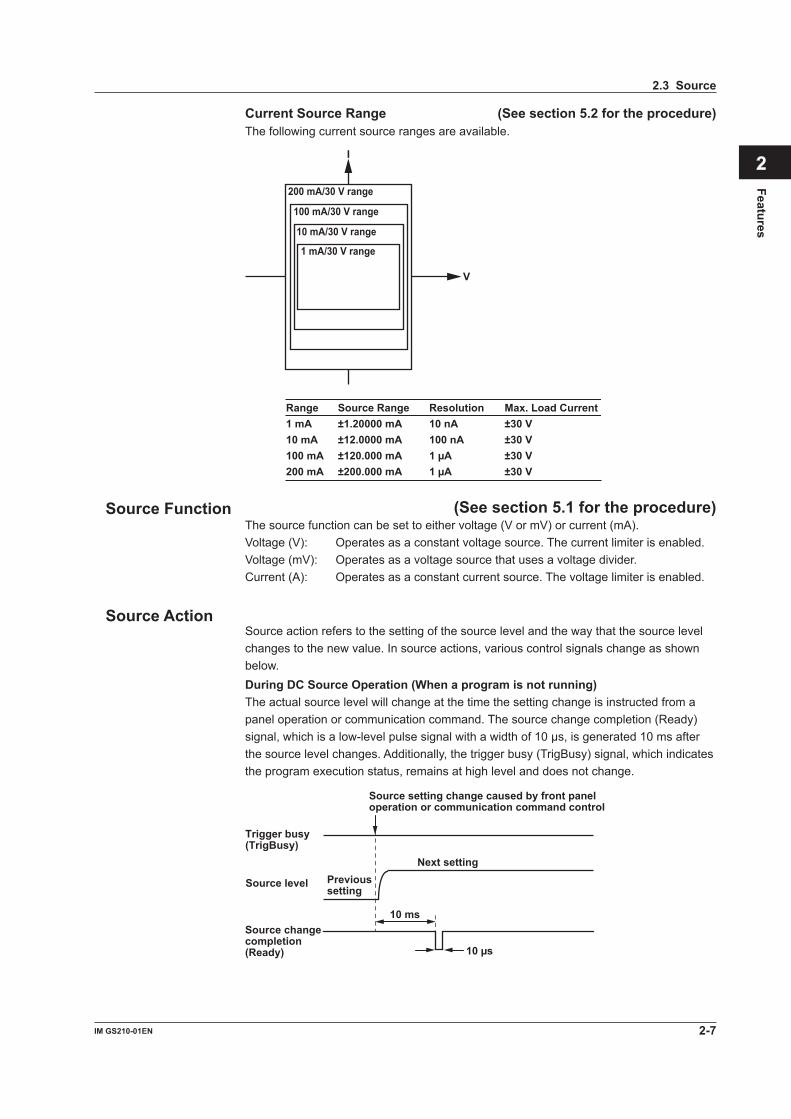
Current Source Range (See section 5.2 for the procedure)The following current source ranges are available.
V
I
100 mA/30 V range
10 mA/30 V range
1 mA/30 V range
Range Source Range Resolution Max. Load Current 1 mA ±1.20000 mA 10 nA ±30 V 10 mA ±12.0000 mA 100 nA ±30 V 100 mA ±120.000 mA 1 µA ±30 V 200 mA ±200.000 mA 1 µA ±30 V
200 mA/30 V range
Source Function (See section 5.1 for the procedure)The source function can be set to either voltage (V or mV) or current (mA).Voltage (V): Operates as a constant voltage source. The current limiter is enabled.Voltage (mV): Operates as a voltage source that uses a voltage divider.Current (A): Operates as a constant current source. The voltage limiter is enabled.
Source ActionSource action refers to the setting of the source level and the way that the source level changes to the new value. In source actions, various control signals change as shown below.During DC Source Operation (When a program is not running)The actual source level will change at the time the setting change is instructed from a panel operation or communication command. The source change completion (Ready) signal, which is a low-level pulse signal with a width of 10 μs, is generated 10 ms after the source level changes. Additionally, the trigger busy (TrigBusy) signal, which indicates the program execution status, remains at high level and does not change.
Source setting change caused by front panel operation or communication command control
Trigger busy (TrigBusy)
Source change completion (Ready)
Source level Previous setting
Next setting
10 ms
10 µs
2.3 Source
2-7IM GS210-01EN
Features
3
2
1
4
5
6
7
8
9
10
11
12
13
14
15
App
Index

During Program ExecutionWhen you execute a program, the trigger busy signal is set to low level, and the source level changes. The source change completion (Ready) signal, which is a low-level pulse signal, is generated 10 ms after the source level changes. When each program interval time completes, the trigger busy signal is set to high level. The program proceeds from step to step by repeating this pattern.
RUN key
Trigger busy (TrigBusy)
Source change completion (Ready)
Source level
Ti Ti
Ti: Program interval time
10 ms
Output ON/OFF (See section 5.5 for the procedure)There are two output modes: OFF or ON.OFF: The output is disconnected, and the specified source level is not generated. In
this mode, program and measurement functions are disabled.ON: The output is connected, and the specified source level is generated. In this
mode, program and measurement functions are enabled.
NoteA mechanical relay operates when the GS200 switches between output on and output off. Note the following points when using the GS200.
• It takes approximately 20 ms for the relay to stabilize.• As the number of on/off operations increases, effects begin to appear such as the relay
taking longer to stabilize. Though dependent on the load, the electrical life of the relay is around 100,000 operations.
DUT Protection Using Limiters (See section 5.4 for the procedure)
CAUTIONIf a current source that exceeds the current limiter setting is connected in voltage source mode; if a voltage source that exceeds the voltage limiter setting is connected in current source mode; or if a load that exceeds the source range listed above is connected, an abnormal load is detected, and the output is turned off (the output trips). Do not connect these types of loads to the GS200. Doing so may damage the instrument.
2.3 Source
2-8 IM GS210-01EN

French
ATTENTIONSi vous raccordez une source de courant en mode source de tension dépassant le paramètre du limiteur de courant, ou une source de tension en mode source de courant dépassant le paramètre du limiteur de tension, ou encore une charge dépassant la plage de la source ci-dessus, une charge anormale est détectée et la sortie est mise hors tension. Ne connectez pas ces types de charge au GS200, ce dernier risquerait de ne pas fonctionner correctement.
Voltage Limiter and Current LimiterIf a limiter is set, an additional limit can be placed within the source range. This limit can prevent damage to the connected device due to overcurrent or overvoltage. In voltage source mode, the current limiter is enabled. In current source mode, the voltage limiter is enabled.
Limiter Operation in Voltage Source Mode
I
V
Source voltage level High limit value
Low limit value
Operating range
Limiter Operation in Current Source Mode
I
V
High limit value Low limit value
Operating range
Source current level
A limiter has an operating range which is defined by a positive value and a negative value in relation to 0. The positive value is the high limit. The negative value is the low limit.If the high limiter is activated, the high limiter indicator (H) is displayed. If the low limiter is activated, the low limiter indicator (L) is displayed.
2.3 Source
2-9IM GS210-01EN
Features
3
2
1
4
5
6
7
8
9
10
11
12
13
14
15
App
Index

Tripping the OutputIf the GS200’s output exceeds the high limiter or falls below the low limiter, the output is automatically turned off. If this occurs, the error indicator illuminates, and the event is written to the error log.
Local Sense and Remote Sense (See section 4.2 for the procedure)Two wiring systems, 2W (two-terminal connection or local sense) and 4W (four-terminal connection or remote sense) are available. In voltage source mode, when the current flowing through the load becomes large, the voltage drop in the lead wire can no longer be ignored. If this occurs, you can select the four-terminal connection and connect the SENSE terminal near the DUT so that the voltage at the connected location is adjusted to the specified voltage. This alleviates the effects from lead wire resistance, and the desired voltage can be applied to the DUT.
Guard Terminal Feature (See section 4.3 for the procedure)If the GS200 and the DUT are far apart or if the GS200 shares its power source with electric motors, common mode noise may be superimposed on the power source signal supplied to the DUT. If common mode noise is superimposed on the signal between the GS200’s Hi and Lo terminals, the noise current enters the internal source circuit from the output terminals and changes the generated signal. To reduce this effect, a shield for the source circuit is connected to the guard terminal of the GS200. If you connect the noise source to the guard terminal, the noise current passes through the guard and is grounded, bypassing the internal source circuit. This reduces the amount of noise that enters the circuit from the connected power source. Use the guard terminal when a large amount of common mode noise is superimposed on the power source signal.
2.3 Source
2-10 IM GS210-01EN

2.4 Programs
Program Feature (See section 6.1 for the procedure)The program feature enables you generate the source data pattern that you specified as a program in advance. Each step in the program is executed in order, and each step has a fixed execution time. You can also set the slope time, so you can generate step responses, ramp responses, and various waveforms such as triangular waveforms.
To create and load programs you can:• Create and edit programs from the GS200 screen.• Create programs on a PC, save them to the GS200’s internal memory (GS200ROM)
as program files in CSV format, and load them from the internal disk.
Source data that programs can contain:• The source level.• The source range.• The source function.
Programs can contain up to 10000 steps. If the number of steps exceeds 10000, only the first 10000 steps are loaded.
Program Interval Time (See section 6.2 for the procedure)The program interval time specifies the execution interval for each step in the program.
1 V
4 V
2 V 1 V
5 V
7 V
Ti Ti: Program interval time
Ti Ti Ti Ti Ti
Program Slope Time (See section 6.3 for the procedure)The program slope time specifies the amount of time that the GS200 takes to linearly change (increase or decrease) the current step’s source level to the next step’s source level from the beginning of the step. The slope of this linear line is calculated as follows:
Program slope time
Next step’s source level – current step’s source level
2-11IM GS210-01EN
Features
3
2
1
4
5
6
7
8
9
10
11
12
13
14
15
App
Index

Ts: Program slope timeTi: Program interval time* The TrigBusy signal’s state transitions shown here assume that the program
trigger is set to Norm.
Ti Ti
Ts < Ti
Ti Ti
Ts = 0
Ti Ti
Ts > Ti
Ti Ti
Ts = Ti
Ts
Ts
RUN key
TrigBusy
Ready
TrigBusy
Ready
RUN key
RUN key RUN key
When Ts is greater than Ti, the situation shown in the bottom right section of the figure above occurs, so be sure to make Ts less than or equal to Ti.
Repeating Programs (See section 6.1 for the procedure)If you specify to repeat programs, after the last step in a program finishes, the first step in the program begins executing.
Program Triggers (See section 6.4 for the procedure)Depending on the program trigger setting, there are the following two types of program operation.When Program Triggers Are Set to Normal (Norm)You can use the RUN, STEP, and HOLD keys and external triggers to control the program execution.
RUN key: Executes the program from step 1.STEP key: Executes only one program step.HOLD key: Pauses the program execution or resumes execution of a paused program.
The program interval time specifies the execution interval for each step in the program.
When Program Triggers Are Set to Measurement End (M.End; only on models with the /MON option)The program executes the source and measurement operations of each step in the minimum time required. The RUN, STEP, and HOLD keys and external triggers are disabled. Additionally, the program interval setting is ignored.
2.4 Programs
2-12 IM GS210-01EN
Program FilesYou can use the USB storage feature (see page 2-25) to store programs in the PROGRAM folder in the GS200’s non-volatile disk (GS200ROM).Prgm01.csv and Prgm02.csv that are stored in the PROGRAM folder when the GS200 is sent from the factory or when you format its disk are program file samples. You can check the contents of program files on the display.
Program File Contents (See section 6.5 for the procedure)Program files are text files that have been created and edited in spreadsheet applications or text editors. Each file contains multiple lines, and each line represents one step in the program.
1 V
4 V
2 V1 V
5 V
7 V1,10,V 4,10,V2,10,V1,10,V5,10,V7,10,V
Program file
Source level, source range, source function
Ti Ti: Program interval time
Ti Ti Ti Ti Ti
LineA line is a string of text that is delimited with line-feed codes (LF or CR+LF). Each line defines the following items (from left to right).• The source level: Defined with an integer or a real number.
Examples: 1, 0.485, –12E–3• The source range: Defined with an integer or a real number.
Examples: The same as the examples given above.• The source function: Defined with a character (V or I).
Make the program file a .CSV file by using a separator (choose either a comma or a semicolon) to separate each item. You can also include white space (space or tab characters) before and after each item.You can omit the source range and source function. If any items are omitted, the same item from the previous step is used. If the source function is not defined in the program’s first step, the source function that the GS200 was using when the program file was loaded is used. If the source range is not defined in the program’s first step, the source range is set to the most appropriate range for the source level that is defined in the program’s first step.
CommentsYou can include comments in program files. A comment consists of any text between “//” and a line-feed code or the end of the file. The GS200 ignores comments when it loads program files.
2.4 Programs
2-13IM GS210-01EN
Features
3
2
1
4
5
6
7
8
9
10
11
12
13
14
15
App
Index
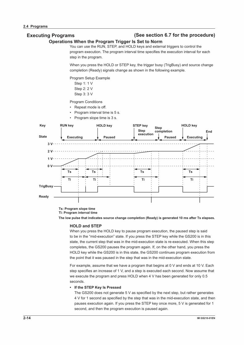
Executing Programs (See section 6.7 for the procedure)Operations When the Program Trigger Is Set to Norm
You can use the RUN, STEP, and HOLD keys and external triggers to control the program execution. The program interval time specifies the execution interval for each step in the program.
When you press the HOLD or STEP key, the trigger busy (TrigBusy) and source change completion (Ready) signals change as shown in the following example.
Program Setup Example Step 1: 1 V Step 2: 2 V Step 3: 3 V
Program Conditions• Repeat mode is off.• Program interval time is 5 s.• Program slope time is 3 s.
Ts: Program slope timeTi: Program interval time
Ti Ti
RUN key
TrigBusy
Ready
HOLD key STEP key HOLD key
Ts Ts Ts Ts
Ti Ti
Executing Paused
Step execution
Paused Executing End
Step completion
State
Key
0 V
1 V
2 V
3 V
The low pulse that indicates source change completion (Ready) is generated 10 ms after Ts elapses.
HOLD and STEPWhen you press the HOLD key to pause program execution, the paused step is said to be in the “mid-execution” state. If you press the STEP key while the GS200 is in this state, the current step that was in the mid-execution state is re-executed. When this step completes, the GS200 pauses the program again. If, on the other hand, you press the HOLD key while the GS200 is in this state, the GS200 continues program execution from the point that it was paused in the step that was in the mid-execution state.
For example, assume that we have a program that begins at 0 V and ends at 10 V. Each step specifies an increase of 1 V, and a step is executed each second. Now assume that we execute the program and press HOLD when 4 V has been generated for only 0.5 seconds.• If the STEP Key Is Pressed The GS200 does not generate 5 V as specified by the next step, but rather generates
4 V for 1 second as specified by the step that was in the mid-execution state, and then pauses execution again. If you press the STEP key once more, 5 V is generated for 1 second, and then the program execution is paused again.
2.4 Programs
2-14 IM GS210-01EN
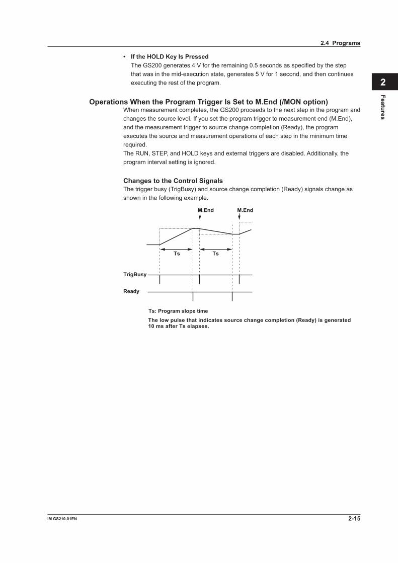
• If the HOLD Key Is Pressed The GS200 generates 4 V for the remaining 0.5 seconds as specified by the step
that was in the mid-execution state, generates 5 V for 1 second, and then continues executing the rest of the program.
Operations When the Program Trigger Is Set to M.End (/MON option)When measurement completes, the GS200 proceeds to the next step in the program and changes the source level. If you set the program trigger to measurement end (M.End), and the measurement trigger to source change completion (Ready), the program executes the source and measurement operations of each step in the minimum time required.The RUN, STEP, and HOLD keys and external triggers are disabled. Additionally, the program interval setting is ignored.
Changes to the Control SignalsThe trigger busy (TrigBusy) and source change completion (Ready) signals change as shown in the following example.
Ts: Program slope time
M.End
TrigBusy
Ready
Ts
M.End
Ts
The low pulse that indicates source change completion (Ready) is generated10 ms after Ts elapses.
2.4 Programs
2-15IM GS210-01EN
Features
3
2
1
4
5
6
7
8
9
10
11
12
13
14
15
App
Index
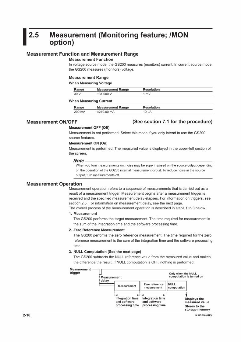
2.5 Measurement (Monitoring feature; /MON option)
Measurement Function and Measurement RangeMeasurement FunctionIn voltage source mode, the GS200 measures (monitors) current. In current source mode, the GS200 measures (monitors) voltage.
Measurement RangeWhen Measuring Voltage
Range Measurement Range Resolution30 V ±31.000 V 1 mV
When Measuring CurrentRange Measurement Range Resolution200 mA ±210.00 mA 10μA
Measurement ON/OFF (See section 7.1 for the procedure)Measurement OFF (Off)Measurement is not performed. Select this mode if you only intend to use the GS200 source features.Measurement ON (On)Measurement is performed. The measured value is displayed in the upper-left section of the screen.
NoteWhen you turn measurements on, noise may be superimposed on the source output depending on the operation of the GS200 internal measurement circuit. To reduce noise in the source output, turn measurements off.
Measurement OperationMeasurement operation refers to a sequence of measurements that is carried out as a result of a measurement trigger. Measurement begins after a measurement trigger is received and the specified measurement delay elapses. For information on triggers, see section 2.6. For information on measurement delay, see the next page.The overall process of the measurement operation is described in steps 1 to 3 below.1. Measurement The GS200 performs the target measurement. The time required for measurement is
the sum of the integration time and the software processing time.2. Zero Reference Measurement The GS200 performs the zero reference measurement. The time required for the zero
reference measurement is the sum of the integration time and the software processing time.
3. NULL Computation (See the next page) The GS200 subtracts the NULL reference value from the measured value and makes
the difference the result. If NULL computation is OFF, nothing is performed.
Measurement trigger
Measurement delay
Displays the measured valueStores to the storage memory
NULLcomputation
Integration time and software processing time
Measurement Zero reference measurement
Integration time and software processing time
Only when the NULL computation is turned on
2-16 IM GS210-01EN

Note• If you change GS200 settings while measurements are being performed, those
measurements are invalid. The measured result display shows “-----,” and you cannot store the results.
• Software processing time is less than 1 ms.
Measurement Delay (See section 7.3 for the procedure)Measurement delay is the wait time from when a measurement trigger is applied to when the measurement operation is carried out. You can adjust the timing between the measurement trigger and the measurement operation by changing this setting. For example, you can set the time needed for the DUT to stabilize after source change completion to the measurement trigger, so that measurement is performed when the DUT has stabilized.
Highly Accurate Measurement and High-Speed MeasurementDepending on the settings, the following measurement conditions enable you to perform highly accurate measurements or high-speed measurements.
Local Sense and Remote Sense (See section 4.2 for the procedure)Two wiring systems, 2W (two-terminal connection or local sense) and 4W (four-terminal connection or remote sense) are available (see page 2-10). When the DUT allows a large output current to flow, the voltage drops due to wire resistance. 4W is effective in this kind of situation. In voltage source mode, you can minimize the effect of wire resistance and measure the voltage that is applied to the DUT. In current source mode, you can minimize the effect of wire resistance and measure the voltage that the DUT generates.
Integration Time (See section 7.2 for the procedure)An integrating A/D converter is used for measurements. If you set a long integration time, the measurement takes longer, but the stability of the measured values increases.
Offset Calibration FeatureZero Calibration (Manual Zero) Feature (See section 7.7 for the procedure)If zero calibration is executed from the GS200’s operation menu, output is automatically turned off, the zero reference is measured, and the zero reference is applied to subsequent measured results. The zero point may change due to the passage of time, the GS200 being in an environment where the temperature changes drastically, or due to other factors. By executing zero calibration, the zero point is calibrated, and this enables the GS200 to generate more accurate output.
NULL Computation (See section 7.6 for the procedure)In NULL computation, the GS200 can display a difference from a given measured value. When you turn NULL computation on, the next measured value is taken to be the NULL value. For subsequent measured values, the measured results are obtained by subtracting this NULL value.
Measured result = measured value – NULL value
2.5 Measurement (Monitoring feature; /MON option)
2-17IM GS210-01EN
Features
3
2
1
4
5
6
7
8
9
10
11
12
13
14
15
App
Index
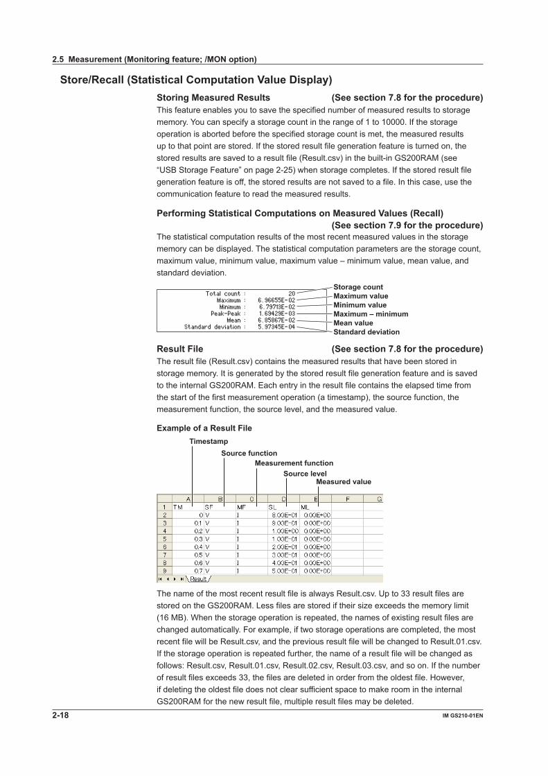
Store/Recall (Statistical Computation Value Display)Storing Measured Results (See section 7.8 for the procedure)This feature enables you to save the specified number of measured results to storage memory. You can specify a storage count in the range of 1 to 10000. If the storage operation is aborted before the specified storage count is met, the measured results up to that point are stored. If the stored result file generation feature is turned on, the stored results are saved to a result file (Result.csv) in the built-in GS200RAM (see “USB Storage Feature” on page 2-25) when storage completes. If the stored result file generation feature is off, the stored results are not saved to a file. In this case, use the communication feature to read the measured results.
Performing Statistical Computations on Measured Values (Recall)(See section 7.9 for the procedure)
The statistical computation results of the most recent measured values in the storage memory can be displayed. The statistical computation parameters are the storage count, maximum value, minimum value, maximum value – minimum value, mean value, and standard deviation.
Maximum – minimumMean valueStandard deviation
Minimum valueMaximum valueStorage count
Result File (See section 7.8 for the procedure)The result file (Result.csv) contains the measured results that have been stored in storage memory. It is generated by the stored result file generation feature and is saved to the internal GS200RAM. Each entry in the result file contains the elapsed time from the start of the first measurement operation (a timestamp), the source function, the measurement function, the source level, and the measured value.
Example of a Result File
Timestamp Source function
Source level Measurement function
Measured value
The name of the most recent result file is always Result.csv. Up to 33 result files are stored on the GS200RAM. Less files are stored if their size exceeds the memory limit (16 MB). When the storage operation is repeated, the names of existing result files are changed automatically. For example, if two storage operations are completed, the most recent file will be Result.csv, and the previous result file will be changed to Result.01.csv. If the storage operation is repeated further, the name of a result file will be changed as follows: Result.csv, Result.01.csv, Result.02.csv, Result.03.csv, and so on. If the number of result files exceeds 33, the files are deleted in order from the oldest file. However, if deleting the oldest file does not clear sufficient space to make room in the internal GS200RAM for the new result file, multiple result files may be deleted.
2.5 Measurement (Monitoring feature; /MON option)
2-18 IM GS210-01EN

GS200RAM Containing Result Files
Newest result file
Third newest result fileSecond newest result file
Result File Numbering
Result.csv
Result.01.csv
Result.csv Result.01.csv
Result.csv
Result.02.csv
Newest result file
The file names are automatically updated.
The file names are automatically updated.
When the first storage operation completes
When the second storage operation completes
When the third storage operation completes
Past
Current
Result files stored in the GS200RAM
Reading the Storage Result through Communications(See section 7.9 for the procedure)
You can use the communication feature to read the storage result directly. You can set the format used to read the data to ASCII or binary.In addition, statistical computation values can also be read using the communication feature.
2.5 Measurement (Monitoring feature; /MON option)
2-19IM GS210-01EN
Features
3
2
1
4
5
6
7
8
9
10
11
12
13
14
15
App
Index

2.6 Triggering
OverviewThe GS200 uses program triggers, which are used to start and pause programs, and measurement triggers, which are used to start measurements.
Program Triggers (See section 6.4 for the procedure)This trigger is used to drive programs (see section 2.4). On models with the monitoring (/MON) option, you can select the normal (Norm) or measurement end (M.End) trigger source. On models without the monitoring (/MON) option, only the normal (Norm) trigger source is available.
Normal (Norm)You can use the following four triggers to execute programs.• RUN key Press this key to begin program execution from step 1. The program proceeds one
step each time the program interval time elapses.
• STEP key Press this key to execute only the current step. When the program interval time
elapses, program execution stops.
• HOLD key Press this key to pause the program that is running. If you press this key when a
program is paused, program execution begins again from the exact point in the step that it was previously paused.
• External triggers (External) The falling edge of a signal applied to TRIG IN of the input terminal for synchronous
operation (SYNC IN, see section 8.2) or TRIG IN of the BNC I/O terminal (see section 8.1) on the rear panel is used as a trigger. This trigger performs the same function as the STEP key on the front panel.
Measurement End (M.End; only on models with the /MON option)When the trigger source is set to measurement end, program execution proceeds from one step to the next as soon as the current step’s measurement completes, regardless of the program interval time. You can execute programs at their optimal speed, but program execution always requires the specified integration time (measurement time). However, you have to set the measurement trigger to source change completion (Ready).When the program trigger is M.End, the RUN, STEP, and HOLD keys are disabled, and the program interval time is ignored.
2-20 IM GS210-01EN
Measurement Triggers (/MON option) (See section 7.4 for the procedure)This trigger is used to start a measurement operation (see section 2.5). Select any of the following trigger sources.
• Measurement timer (Timer) You can set the constant period timer to a period from 0.1 seconds to 3600.0 seconds.
The timer is reset when you turn the output on.
• Measurement completion (immediate; Immed) The end of one measurement triggers the beginning of the next measurement. This is
used in situations such as when you need to repeat measurements at high speeds.
• Source change completion (Ready) This is generated 10 ms after the source level is changed.
• Communication commands (Comm) You can use the communication command "*TRG" to start measurements.
2.6 Triggering
2-21IM GS210-01EN
Features
3
2
1
4
5
6
7
8
9
10
11
12
13
14
15
App
Index

Trigger Block Diagram
Meas Trig
Meas Busy
MEASURE
PROGRAM
TrigIn TrigOut
ProgramTrig
TrigBusy
P.In
terv
al
Exte
rnal
Step
M.E
nd
Imm
edTi
mer
Rea
dy
Meas.Timer
P.Interval TimerSTEP
HOLD
RUN
Ready
Com
m
“*TRG”
2.6 Triggering
2-22 IM GS210-01EN
Trigger Output (See sections 8.1 and 8.2 for the procedures)The GS200 can output the program trigger signal from the SYNC OUT terminal (I/O terminals for synchronous operation) or the BNC output terminal to the subsequent GS200s that are connected.TrigOutTrigOut transmits the trigger busy signal.• When program triggers are set to normal (Norm) When a program trigger is generated, this signal is set to low level. When the program
interval time elapses, this signal is set to high level.• When program triggers are set to measurement end (M.End) When a program trigger is generated, this signal is set to low level. Regardless of the
program interval time, this signal is immediately set back to high level.
Trigger HoldYou can pause program execution by pressing the HOLD key on the front panel or by transmitting the communication command “:PROGram:HOLD” or “:PROGram:PAUSe.” To resume program execution, press the HOLD key again, or transmit the communication command “:PROGram:HOLD” or “:PROGram:CONTinue.”
Sampling ErrorIf one of the following invalid triggers occurs, the sampling error indicator on the front panel illuminates.• A new measurement trigger occurred while a measurement operation was in progress.• The RUN or STEP key was pressed or an external trigger signal was received while a
program was running.
NoteIf sampling errors occur, the trigger generation timing may be too fast. If the sampling error indicator illuminates, check settings such as the selected trigger source and timer period.
2.6 Triggering
2-23IM GS210-01EN
Features
3
2
1
4
5
6
7
8
9
10
11
12
13
14
15
App
Index

2.7 Synchronization
SynchronizationYou can connect multiple GS200s and synchronize switching of the output between on and off and their program execution.
External I/OThere are two types of external I/O terminals on the GS200: the I/O terminals for synchronous operation (SYNC In/OUT) and the BNC I/O terminals (IN and OUT).
RJ-11 Connector (I/O terminals for synchronous operation; SYNC IN/OUT)(See section 8.2 for the procedure)
By using the I/O terminals for synchronous operation (SYNC IN/OUT) on the rear panel, you can synchronize the operation of multiple connected GS200s. Use synchronous operation cables (758960) that are sold separately to connect the GS200s in a daisy chain. The first unit is connected to the second unit, the second unit is connected to the third unit, and so on. You can synchronize the operation of program triggers and the output state (output on and off).
BNC I/O (IN and OUT) (See section 8.1 for the procedure)You can use the BNC connectors at the top of the rear panel to apply and transmit any of the following signals as external signals. You can use these connectors for synchronous operation and other purposes.• Output state (output on and off) I/O• Program trigger I/O• Source change completion (Ready) output
2-24 IM GS210-01EN
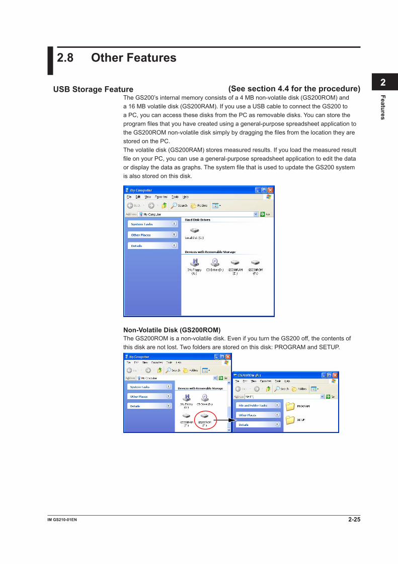
2.8 Other Features
USB Storage Feature (See section 4.4 for the procedure)The GS200’s internal memory consists of a 4 MB non-volatile disk (GS200ROM) and a 16 MB volatile disk (GS200RAM). If you use a USB cable to connect the GS200 to a PC, you can access these disks from the PC as removable disks. You can store the program files that you have created using a general-purpose spreadsheet application to the GS200ROM non-volatile disk simply by dragging the files from the location they are stored on the PC.The volatile disk (GS200RAM) stores measured results. If you load the measured result file on your PC, you can use a general-purpose spreadsheet application to edit the data or display the data as graphs. The system file that is used to update the GS200 system is also stored on this disk.
Non-Volatile Disk (GS200ROM)The GS200ROM is a non-volatile disk. Even if you turn the GS200 off, the contents of this disk are not lost. Two folders are stored on this disk: PROGRAM and SETUP.
2-25IM GS210-01EN
Features
3
2
1
4
5
6
7
8
9
10
11
12
13
14
15
App
Index

PROGRAMThis folder contains all the program output pattern files. All the files in this folder can be used as program files.When the GS200 is sent from the factory, two sample program files are stored in this folder. These sample program files are also created when you format the disk.
SETUPThis folder contains all the panel setup files. Any of the files in this folder can be selected as a setup file.When the GS200 is sent from the factory, a sample setup file is stored in this folder. This sample setup file is also created when you format the disk.
Volatile Disk (GS200RAM)The GS200RAM is a volatile disk. When you turn the GS200 on, this disk is automatically formatted. During storage, the result file (Result.csv) is created on this disk.This disk is normally used to transfer files that the GS200 generates to your PC. However, a system file is transferred from your PC to this disk when you update the system firmware. For details, see section 14.5, “Updating the System Firmware.”
NoteYou can create files and folders on the GS200RAM, but be sure that the disk does not become full. The data on this disk is lost when the GS200 is turned off.
Formatting the DiskYou can format the disk if you want to reset the GS200ROM to the factory default conditions, if the non-volatile or volatile disk cannot be detected by your PC, or if you believe the data on the disk is corrupt.
USB Communication (USB-TMC command control)(See chapter 10 for the procedures)
The GS200 has a USB2.0 device interface. This interface allows access to the USB storage feature as well as allows command control from a VISA (Virtual Instrument Software Architecture) library using a VISA USB-TMC device driver as defined by the VXI Plug&Play System Alliance.
2.8 Other Features
2-26 IM GS210-01EN
Ethernet Communications (/C10 option) (See chapter 11 for the procedures)The GS200 has a LAN interface with auto switching between 10 Mbps and 100 Mbps. You can assign a static IP address or obtain an address dynamically from a DHCP server. The following four features are available.Command Control Using VXI-11The GS200 has an Ethernet VXI-11 device driver. This allows command control from a VISA library.Panel Control Using a Browser (See section 11.5 for the procedure)The GS200 has a Web server feature. This allows you to display the front panel image of the GS200 on a PC’s Web browser and remotely control the GS200 from the Web browser.File Transfer with FTP ClientsUp to five clients can establish FTP connections by way of the anonymous FTP server function. The non-volatile disk (GS200ROM) and volatile disk (GS200RAM) can be handled as a PC file server. Files such as program files can be transferred, and measured result data can be loaded onto a PC through the use of the FTP protocol.For information on the GS200ROM and GS200RAM, see “USB Storage Feature,” on page 2-25.Command Control Using Port 7655The GS200 has a command mnemonic stream parsing server that can connect up to five clients. The terminator (CR, LF, or CR+LF) can be specified.
Because each server feature is independent, you can for example, control the GS200 using commands while it is transferring files using FTP.
GP-IB Communications (See chapter 12 for the procedures)The GS200 has an interface that is used to control the GS200 using commands. You can specify the same settings as you would using the front panel keys of the GS200 and output setup data and measured data. Because the command control of the GS200 is mutually independent, other communication features can be used while you are using GP-IB to control the GS200.
Saving, Loading, and Deleting Setup Data (See section 9.2 for the procedure)The current settings can be saved to a setup file (Setup01.txt to Setup04.txt) on the non-volatile disk (GS200ROM). The saved setup data can be loaded to restore the settings.The setup file is a text file that contains communication commands. This file can be edited later on your PC.For information on the GS200ROM and GS200RAM, see “USB Storage Feature,” on page 2-25.
Selecting the Settings Applied at Power-On (See section 9.3 for the procedure)The GS200 settings at power-on can be changed from the default settings to the settings selected by the user.If the selected file is deleted or renamed, the GS200 will start with its default settings.
2.8 Other Features
2-27IM GS210-01EN
Features
3
2
1
4
5
6
7
8
9
10
11
12
13
14
15
App
Index

3.1 Handling Precautions
Read the Safety PrecautionsSafety PrecautionsIf you are using the GS200 for the first time, make sure to read “Safety Precautions,” on pages vii and xi.
Do Not Remove the CaseDo not remove the case from the instrument. Some sections inside the instrument have high voltages that are extremely dangerous. For internal inspection and adjustment, contact your nearest YOKOGAWA dealer.
Unplug If Abnormal Behavior OccursIf you notice smoke or unusual odors coming from the instrument, immediately turn off the power and unplug the power cord. If these symptoms occur, contact your nearest YOKOGAWA dealer.
Correct the Problem If Output Is Forcibly Turned OffIf the GS200 detects an internal circuit error due to an excessive external input or electrical oscillation, the output is forcibly turned off, the ERROR indicator illuminates, and the error message “An abnormal load is connected” is displayed. If this happens, remove the cause of the problem, such as the external load, and turn the output on again. If the output still turns off after you have corrected the problem, the GS200 may be malfunctioning. Contact your nearest YOKOGAWA dealer. Note that even if the GS200 is returned to normal, the error display remains until you manually clear it (see section 9.6, “Error Log Display”) or use communication commands to read the error information.
Turn the Power Switch Off If Overheat is DetectedIf the GS200 detects an overheat condition such as when the inlet or vent holes for the cooling fan are obstructed or the fan is stopped, the GS200 forcibly turns the output off, displays an “Abnormal Temperature” warning, and produces intermittent beeps. If this happens, immediately turn the power switch off. Check that there is adequate space around the GS200, and check for and remove any foreign objects that are caught in the cooling fan on the rear panel. If the same warning appears when you turn the power switch on after waiting a sufficient amount of time, the GS200 may be malfunctioning. Contact your nearest YOKOGAWA dealer.
Handle the Power Cord with CareNothing should be placed on top of the power cord. The power cord should also be kept away from any heat sources. When unplugging the power cord from the outlet, never pull by the cord itself. Be sure to hold and pull by the plug. If the power cord is damaged or if you are using the instrument in a location where the power supply specifications are different, purchase a power cord that matches the specifications of the region that the instrument will be used in.
Operating Environment and ConditionsThis instrument complies with the EMC standard under specific operating environment and operating conditions. If the installation, wiring, and so on are not appropriate, the compliance conditions of the EMC standard may not be met. In such cases, the user will be required to take appropriate measures.
Chapter 3 Instrument Preparation and Common Operations
3-1IM GS210-01EN
Instrument Preparation and C
omm
on Operations
3
2
1
4
5
6
7
8
9
10
11
12
13
14
15
App
Index
General Handling PrecautionsDo Not Place Objects on Top of the InstrumentNever place objects such as other instruments or objects that contain water on top of the instrument. Doing so may damage the instrument. For details on the installation conditions of the GS200, see section 3.2.
Do Not Apply Shock or VibrationDo not apply shock or vibration. Doing so may damage the instrument. In addition, applying shock to the input/output terminal or the connected cables can cause electrical noise to enter or be generated from the instrument.
Keep Electrically Charged Objects Away from the InstrumentKeep electrically charged objects away from the input and output connectors. They may damage the internal circuitry.
During Extended Periods of Non-UseTurn off the power switch, and remove the power cord from the outlet.
When Carrying the InstrumentFirst, remove the power cord and connection cables. The instrument weighs approximately 5 kg. To carry the instrument, use the handle as shown in the figure below, and move the instrument carefully.
When Cleaning the InstrumentWhen cleaning the case or the operation panel, turn off the power switch, and remove the power cord from the outlet. Then, wipe the instrument lightly with a clean dry cloth. Do not use volatile chemicals such as benzene or thinner for cleaning, as they may lead to discoloration or deformation.
3.1 Handling Precautions
3-2 IM GS210-01EN
3.2 Installation
Installation Orientation
WARNING• To prevent fire, never use the instrument with the rear panel facing down. There
are vent holes for the cooling fan on the rear panel. Placing the instrument with the rear panel facing down may cause a fire when the instrument malfunctions.
• This instrument is designed to be used indoors. Do not install or use it outdoors.• Install the instrument so that you can immediately remove the power cord if an
abnormal or dangerous condition occurs.
CAUTIONIf you block the inlet or outlet holes on the GS200, the GS200 will become hot and may break down.
French
AVERTISSEMENT• Pour éviter tout incendie, n’utilisez jamais l’instrument lorsque le panneau
arrière est orienté vers le bas. En effet, le panneau arrière comprend des orifices destinés au ventilateur de refroidissement. S’il est orienté vers le bas, un incendie risque de survenir en cas de dysfonctionnement de l’instrument.
• L’instrument est prévu pour une utilisation en intérieur. Ne pas l’installer, ni l’utiliser à l’extérieur.
• Installer l’instrument de manière à pourvoir immédiatement le débrancher du secteur en cas de fonctionnement anormal ou dangereux.
ATTENTIONNe pas boucher les orifices d’entrée ou de sortie du GS200 pour éviter toute surchauffe et panne éventuelle.
3-3IM GS210-01EN
Instrument Preparation and C
omm
on Operations
3
2
1
4
5
6
7
8
9
10
11
12
13
14
15
App
Index
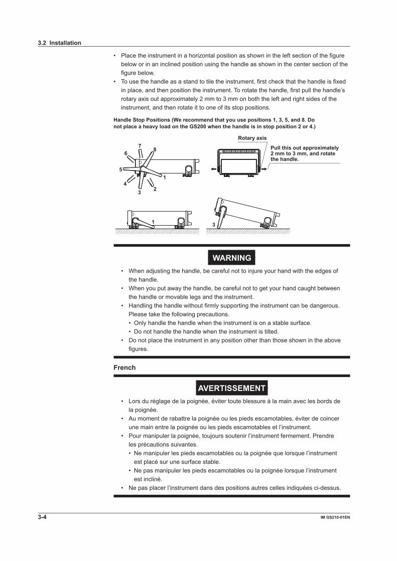
• Place the instrument in a horizontal position as shown in the left section of the figure below or in an inclined position using the handle as shown in the center section of the figure below.
• To use the handle as a stand to tile the instrument, first check that the handle is fixed in place, and then position the instrument. To rotate the handle, first pull the handle’s rotary axis out approximately 2 mm to 3 mm on both the left and right sides of the instrument, and then rotate it to one of its stop positions.
Rotary axis
Handle Stop Positions (We recommend that you use positions 1, 3, 5, and 8. Do not place a heavy load on the GS200 when the handle is in stop position 2 or 4.)
Pull this out approximately 2 mm to 3 mm, and rotate the handle.
1
234
5
67 8
31
WARNING• When adjusting the handle, be careful not to injure your hand with the edges of
the handle.• When you put away the handle, be careful not to get your hand caught between
the handle or movable legs and the instrument.• Handling the handle without firmly supporting the instrument can be dangerous.
Please take the following precautions. • Only handle the handle when the instrument is on a stable surface. • Do not handle the handle when the instrument is tilted.• Do not place the instrument in any position other than those shown in the above
figures.
French
AVERTISSEMENT• Lors du réglage de la poignée, éviter toute blessure à la main avec les bords de
la poignée.• Au moment de rabattre la poignée ou les pieds escamotables, éviter de coincer
une main entre la poignée ou les pieds escamotables et l’instrument.• Pour manipuler la poignée, toujours soutenir l’instrument fermement. Prendre
les précautions suivantes. • Ne manipuler les pieds escamotables ou la poignée que lorsque l’instrument
est placé sur une surface stable. • Ne pas manipuler les pieds escamotables ou la poignée lorsque l’instrument
est incliné.• Ne pas placer l’instrument dans des positions autres celles indiquées ci-dessus.
3.2 Installation
3-4 IM GS210-01EN
Installation ConditionsInstall the instrument in a place that meets the following conditions.Ambient Temperature and HumidityUse the instrument in the following environment.• Ambient temperature: 5°C to 40°C However, when you want to generate output with high accuracy, operate the
instrument in the 23°C ± 5°C temperature range.• Ambient humidity: 20% RH to 80% RH No condensation should be present.
NoteCondensation may form when moving the GS200 from a low temperature or humidity environment to a high temperature or humidity environment, or when there is a sudden change in temperature. In these kinds of circumstances, wait for at least an hour before using the GS200, to acclimate it to the surrounding environment. If you transport the instrument in its packing box, to prevent condensation, allow it to adjust to the new ambient temperature for at least an hour before taking it out of the box.
Flat and Even LocationPlace the instrument on a flat, even surface. Do not place the instrument on an unstable or sloped surface.
Well-Ventilated LocationThere are inlet holes on the bottom side of the instrument. In addition, there are vent holes for the cooling fan on the rear panel. To prevent internal overheating, allow for enough space around the instrument (see the figure below), and do not block the inlet and vent holes.
10 cm or more
5 cm or more 5 cm or more
10 cm or more
Provide adequate space around the GS200.
3.2 Installation
3-5IM GS210-01EN
Instrument Preparation and C
omm
on Operations
3
2
1
4
5
6
7
8
9
10
11
12
13
14
15
App
Index
Do Not Install the Instrument in the Following Places• Outdoors• In direct sunlight or near sources of heat• Where the instrument is exposed to water or other liquids• Where an excessive amount of soot, steam, dust, or corrosive gas is present• Near sources of strong magnetic fields• Near high-voltage equipment or power lines• In an environment that is subject to large levels of mechanical vibration• On an unstable surface
Storage LocationWhen storing the instrument, avoid the following places.• Where the relative humidity is 80% or higher• In direct sunlight• Where the temperature is 60°C or higher• Near a strong source of heat or moisture• Where the level of mechanical vibration is high• Where there are corrosive or explosive gasses• Where an excessive amount of soot, dust, salt, or iron is present• Where water, oil, or chemicals may splashWe recommend that the instrument be stored in an environment where the temperature is between 5°C and 40°C and the relative humidity is between 20% RH and 80% RH.
Rack MountTo mount the instrument in a rack, use the separately sold rack mount kit. For the procedure to rack mount the GS200, see the instructions that are included with the rack mount kit.
Name Model NoteRack mount kit 751533-E2 For EIA single mountRack mount kit 751534-E2 For EIA dual mountRack mount kit 751533-J2 For JIS single mountRack mount kit 751534-J2 For JIS dual mount
3.2 Installation
3-6 IM GS210-01EN

3.3 Connecting the Power Supply
Before Connecting the Power SupplyTo prevent electric shock and damage to the instrument, follow the warnings below.
WARNING• Make sure that the power supply voltage matches the instrument’s rated supply
voltage and that it does not exceed the maximum voltage range of the power cord to use.
• Connect the power cord after checking that the power switch of the instrument is turned OFF.
• To prevent electric shock or fire, use the power cord for the instrument.• Make sure to connect protective earth grounding to prevent electric shock.
Connect the power cord to a three-prong power outlet with a protective earth terminal.
• Do not use an extension cord without protective earth ground. The protective features of the instrument will be rendered ineffective.
• If there is no AC outlet that is compatible with the power cord that you will be using and you cannot ground the instrument, do not use the instrument.
French
AVERTISSEMENT• Assurez-vous que la tension d’alimentation correspond à la tension d’alimentation
nominale de l’appareil et qu’elle ne dépasse pas la plage de tension maximale du cordon d’alimentation à utiliser.
• Brancher le cordon d’alimentation après avoir vérifié que l’interrupteur de l’instrument est sur OFF.
• Pour éviter tout risque de choc électrique, utiliser exclusivement le cordon d’alimentation prévu pour cet instrument.
• Relier l’instrument à la terre pour éviter tout risque de choc électrique. Brancher le cordon d’alimentation sur une prise de courant à trois plots reliée à la terre.
• Toujours utiliser une rallonge avec broche de mise à la terre, à défaut de quoi l’instrument ne serait pas relié à la terre.
• Si une sortie CA conforme au câble d’alimentation fourni n’est pas disponible et que vous ne pouvez pas relier l’instrument à la terre, ne l’utilisez pas.
3-7IM GS210-01EN
Instrument Preparation and C
omm
on Operations
3
2
1
4
5
6
7
8
9
10
11
12
13
14
15
App
Index

Connecting the Power Cord1. Check that the instrument’s power switch is off.
2. Connect the instrument’s power cord to the power inlet on the rear panel.
3. Connect the other end of the cord to an outlet that meets the conditions below. The AC outlet must be of a three-prong type with a protective earth ground terminal.
Item SpecificationsSuffix Code -1 -4 -7Rated power supply voltage 100 VAC 120 VAC 230 VACPermitted power supply voltage range 90 VAC to 110 VAC 108 VAC to 132 VAC 207 VAC to 253 VAC Rated power supply frequency 50/60 HzPermitted power supply 48 Hz to 63 Hz frequency rangeMaximum power consumption Approx. 80 VA* The supply voltage that the GS200 can use differs depending on its suffix code. Check that the voltage
supplied to the instrument is less than or equal to the maximum rated voltage of the power cord that you will be using before use.
Three-prong outlet
Power cord
3.3 Connecting the Power Supply
3-8 IM GS210-01EN
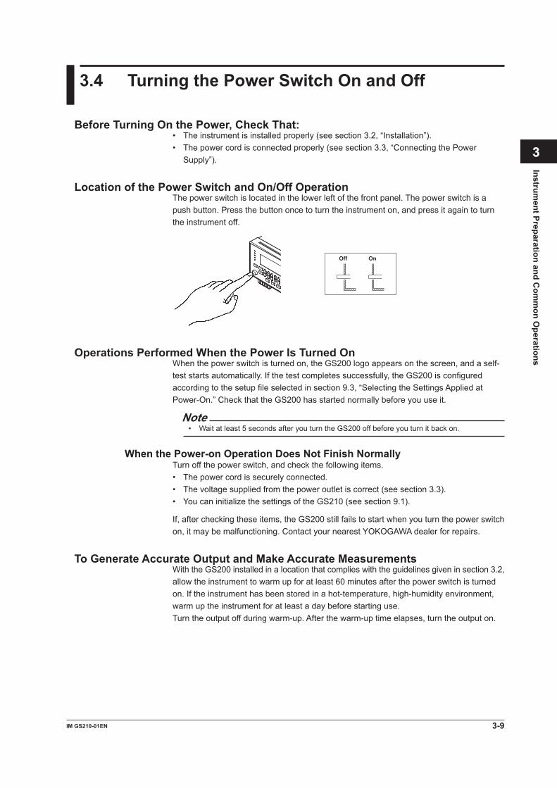
3.4 Turning the Power Switch On and Off
Before Turning On the Power, Check That:• The instrument is installed properly (see section 3.2, “Installation”).• The power cord is connected properly (see section 3.3, “Connecting the Power
Supply”).
Location of the Power Switch and On/Off OperationThe power switch is located in the lower left of the front panel. The power switch is a push button. Press the button once to turn the instrument on, and press it again to turn the instrument off.
Off On
Operations Performed When the Power Is Turned OnWhen the power switch is turned on, the GS200 logo appears on the screen, and a self-test starts automatically. If the test completes successfully, the GS200 is configured according to the setup file selected in section 9.3, “Selecting the Settings Applied at Power-On.” Check that the GS200 has started normally before you use it.
Note• Wait at least 5 seconds after you turn the GS200 off before you turn it back on.
When the Power-on Operation Does Not Finish NormallyTurn off the power switch, and check the following items.• The power cord is securely connected.• The voltage supplied from the power outlet is correct (see section 3.3).• You can initialize the settings of the GS210 (see section 9.1).
If, after checking these items, the GS200 still fails to start when you turn the power switch on, it may be malfunctioning. Contact your nearest YOKOGAWA dealer for repairs.
To Generate Accurate Output and Make Accurate MeasurementsWith the GS200 installed in a location that complies with the guidelines given in section 3.2, allow the instrument to warm up for at least 60 minutes after the power switch is turned on. If the instrument has been stored in a hot-temperature, high-humidity environment, warm up the instrument for at least a day before starting use.Turn the output off during warm-up. After the warm-up time elapses, turn the output on.
3-9IM GS210-01EN
Instrument Preparation and C
omm
on Operations
3
2
1
4
5
6
7
8
9
10
11
12
13
14
15
App
Index

Operations Performed When the Power Is Turned OffThe setup data and measured results immediately before the power switch is turned off are not retained. The same is true when the power cord is disconnected from the outlet. We recommend that you save important setup data to the SETUP folder on the non-volatile disk (GS200ROM). See sections 2.8, “USB Storage Feature” and 9.2.
NoteThe GS200 may produce a momentary beeping sound, but this sound does not indicate an error.
CAUTIONDo not turn off the power when the instrument’s output is turned on. Doing so can damage the GS200. It can also cause damage to the devices connected to the GS200. Turn the output off first, and the turn off the power.
French
ATTENTIONNe pas tourner l’appareil hors tension quand la sortie de l’instrument est activée. Cela peut endommager le GS200. Il peut aussi endommager les appareils connectés à la GS200.Tourner la sortie première et la coupez l’alimentation.
3.4 Turning the Power Switch On and Off
3-10 IM GS210-01EN

3.5 Wiring Precautions
WARNINGBefore Wiring• Ground the instrument before connecting the instrument to the target device.
The power cord to use is a three-prong type power cord. Insert the power cord into a grounded three-prong outlet.
• Be sure to turn the GS200 output off before you connect the device that you are generating output for.
Wiring• Only use cables whose conductive parts are covered for connecting to the
output terminals. Exposed conductive parts can lead to electric shock.• Do not use cables whose conductive parts are exposed due to tears in the
insulation or broken cables as they may lead to a short circuit or electric shock.• Do not connect a voltage source in voltage source mode or a current source in
current source mode. An incorrect connection may damage the GS200.• Do not connect a load that exceeds ±32 V or ±200 mA across the OUTPUT Hi
and OUTPUT Lo terminals or across the SENSE Hi and SENSE Lo terminals.• The maximum allowable voltage between the case and each terminal is ±250
Vpeak. Applying a voltage that exceeds this value may damage the GS200.• Keep the voltage that is generated across OUTPUT Hi and SENSE Hi and
across OUTPUT Lo and SENSE Lo to less than or equal to ±0.5 Vpeak.• When making a four-terminal connection, be careful that the connection to
the SENSE terminals does not get cut. If the voltage is not sensed correctly, abnormal voltage may be generated across the OUTPUT Hi and OUTPUT Lo terminals.
• When making a two-terminal connection, use the OUTPUT terminals. If the SENSE terminals are used, the current flows through the SENSE line. This prohibits the GS200 from generating correct output and can damage the GS200.
• If you are using the instrument in a floating condition and there is a risk of dangerous voltage, only use lead wires that have safety terminals that cover their conductive parts. Using a terminal with bare conductive parts (such as a banana plug) can be dangerous if the terminal comes loose.
• If you are using the instrument in a floating condition and there is a risk of dangerous voltage, do not use the fork terminal adapter set 758921. Due to the structure of the product, it is possible to touch the metal parts of the fork terminal adapter 758921. Be careful as this constitutes an electric shock hazard.
• Use the accessories of this product within the rated range of each accessory (see page v). When using several accessories together, use them within the specification range of the accessory with the lowest rating.
CAUTION• Use conducting wires that have adequate margins of withstand voltage and
current capacity with respect to the voltage or current to be used.
3-11IM GS210-01EN
Instrument Preparation and C
omm
on Operations
3
2
1
4
5
6
7
8
9
10
11
12
13
14
15
App
Index

• To prevent oscillations due to stray capacitance and lead inductance, use twisted-pair lead wires to connect to the OUTPUT Hi and OUTPUT Lo terminals. Likewise, use twisted-pair lead wires to connect to the SENSE Hi and SENSE Lo terminals. In particular, wire the lead wires short in the case of a high-capacity load in a four-terminal connection in voltage source mode.
• When using the 10 mV or 100 mV range, do not apply external voltage or current. Also, do not connect to charged capacitive loads.
If you output high voltage or if the voltage limiter is activated while outputting current when a capacitive load is connected, be careful as the capacitor will be charged with high voltage. Applying external voltage or current may damage the voltage divider inside the GS200.
French
AVERTISSEMENTAvant le câblage• Relier l’instrument à la terre avant de le brancher sur l’appareil cible. Le cordon
d’alimentation à utiliser est un cordon d’alimentation à trois broches. Brancher le cordon d’alimentation sur une prise de courant à trois plots mise à la terre.
• Veillez à mettre le GS200 hors tension lorsque vous connectez le dispositif à tester.
Câblage• Utilisez seulement des câbles en plomb dont les pièces conductrices
sont recouvertes pour un raccordement aux bornes de sortie. Des pièces conductrices exposées peuvent entraîner une choc électrique.
• N’utilisez pas de câble de plomb dont les pièces conductrices sont exposées, en raison de traces d’usure de l’isolation ou de câbles cassés, car ceci risque d’entraîner un court-circuit ou un choc électrique.
• Ne raccordez pas une source de tension en mode source de tension ou une source de courant en mode source de courant. Un raccordement incorrect risque d’endommager le GS200.
• Ne connectez pas une charge supérieure à ± 32 V ou ± 200 mA entre les bornes OUTPUT Hi et OUTPUT Lo ou entre les bornes SENSE Hi et SENSE Lo.
• La tension maximale autorisée entre le boîtier et chacune des bornes est de ±250 Vcrête. L’application d’une tension dépassant cette valeur risque d’endommager le GS200.
• Maintenez une tension entre les bornes OUTPUT Hi et SENSE Hi et OUTPUT Lo et SENSE Lo inférieure ou égale à ±0,5 Vcrête.
• Lors d’une connexion aux quatre bornes, veillez à ce que la connexion aux bornes SENSE ne soit pas coupée. Si la tension n’est pas correctement détectée, une tension anormale est générée entre les bornes OUTPUT Hi et OUTPUT Lo.
• Lors d’une connexion à deux bornes, utilisez les bornes OUTPUT. Si vous utilisez les bornes SENSE, les courants circulant dans la ligne SENSE empêchent le GS200 de fonctionner normalement et entraînent des dommages.
• Si l’instrument est utilisé en condition de flottement et qu’un risque de tension dangereuse est présent, n’utiliser que des câbles en plomb dotés de bornes sécurisées capables de couvrir les éléments conducteurs. L’utilisation d’une borne dotée d’éléments conducteurs nus (comme une fiche banane) serait dangereuse si la borne venait à se détacher.
3.5 Wiring Precautions
3-12 IM GS210-01EN
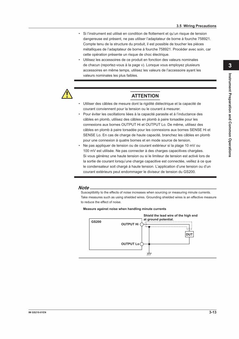
• Si l’instrument est utilisé en condition de flottement et qu’un risque de tension dangereuse est présent, ne pas utiliser l’adaptateur de borne à fourche 758921. Compte tenu de la structure du produit, il est possible de toucher les pièces métalliques de l’adaptateur de borne à fourche 758921. Procéder avec soin, car cette opération présente un risque de choc électrique.
• Utilisez les accessoires de ce produit en fonction des valeurs nominales de chacun (reportez-vous à la page v). Lorsque vous employez plusieurs accessoires en même temps, utilisez les valeurs de l’accessoire ayant les valeurs nominales les plus faibles.
ATTENTION• Utiliser des câbles de mesure dont la rigidité diélectrique et la capacité de
courant conviennent pour la tension ou le courant à mesurer.• Pour éviter les oscillations liées à la capacité parasite et à l’inductance des
câbles en plomb, utilisez des câbles en plomb à paire torsadée pour les connexions aux bornes OUTPUT Hi et OUTPUT Lo. De même, utilisez des câbles en plomb à paire torsadée pour les connexions aux bornes SENSE Hi et SENSE Lo. En cas de charge de haute capacité, branchez les câbles en plomb pour une connexion à quatre bornes et en mode source de tension.
• Ne pas appliquer de tension ou de courant extérieur si la plage 10 mV ou 100 mV est utilisée. Ne pas connecter à des charges capacitives chargées.
Si vous générez une haute tension ou si le limiteur de tension est activé lors de la sortie de courant lorsqu’une charge capacitive est connectée, veillez à ce que le condensateur soit chargé à haute tension. L’application d’une tension ou d’un courant extérieurs peut endommager le diviseur de tension du GS200.
NoteSusceptibility to the effects of noise increases when sourcing or measuring minute currents. Take measures such as using shielded wires. Grounding shielded wires is an effective measure to reduce the effect of noise.
Measure against noise when handling minute currents
GS200 OUTPUT Hi
OUTPUT Lo
DUT
Shield the lead wire of the high end at ground potential.
3.5 Wiring Precautions
3-13IM GS210-01EN
Instrument Preparation and C
omm
on Operations
3
2
1
4
5
6
7
8
9
10
11
12
13
14
15
App
Index

3.6 Wiring the GS211 Rear Panel Terminal Plug
Follow the procedure below to wire the rear panel terminal plug on a GS211, which has rear panel output terminals. To prevent electric shock and damage to the instrument, follow the warnings given in section 3.5, “Wiring Precautions.”
1. Unscrew the screws on the left and right of the terminal plug, and remove the terminal plug from the GS211.
Screw (2)
2. Loosen the screws on the top of the terminal plug (these screws are used to fix cables in place), and insert stripped cables into the holes.
Screw used to fix the cable in place
Cable SENSEHi
SENSELo
OUTPUTLo
GOUTPUTHi
Terminal plug pinout
• Length of stripped cable: 7 mm• Rated connecting capacity
Single wire: 0.2 mm2 to 2.5 mm 2
Twisted wire: 0.2 mm2 to 2.5 mm 2
AWG: 24 to 12
3. Tighten the screws to fix the cables in place (screw tightening torque: 0.5 N•m to 0.6 N•m).
4. Tighten the screws on the left and right of the terminal plug to attach it to the GS211 (screw tightening torque: 0.2 N•m to 0.3 N•m).
3-14 IM GS210-01EN

3.7 Setting the Date, Time, and the Time Difference from GMT (Greenwich Mean Time)
Procedure1. Press UTILITY to display the following menu.
2. Press the Sys Config soft key to display the following menu.
3. Press the Adjust Time soft key.
Setting the Date and Time4. Press the Clock soft key to display the date/time setup screen.
5. Press the Edit soft key.
6. Press a soft key from Year to Second that corresponds to the setting that you want to set.
7. In up/down key mode, press the and keys to set the date and time. In keypad mode, press NUM LOCK + or to set the date and time (see section 4.1).
8. Press the Set soft key to set the value.
Synchronizing the Clock9. Press the Adjust Zero soft key to synchronize the clock by resetting the seconds
to zero.If the seconds value is greater than or equal to 30 seconds, the minutes value increases by 1 minute, and the seconds value is set to 0.
3-15IM GS210-01EN
Instrument Preparation and C
omm
on Operations
3
2
1
4
5
6
7
8
9
10
11
12
13
14
15
App
Index

Setting the Time Difference from GMT (Greenwich Mean Time)4. Press the Time Zone soft key.
5. Press the Edit soft key.
6. Press the Hour or Minute soft key to set the corresponding setting.
7. In up/down key mode, press the and keys to set the date and time. In keypad mode, press NUM LOCK + or to set the date and time.
8. Press the Set soft key to set the value.
ExplanationSetting the Date and Time• Date (Year/Month/Day) The year is displayed according to the Gregorian calendar.• Time (Hour/Minute/Second) The hour can be set to a value from 0 to 23.
Note• The date and time settings are backed up with the internal lithium battery when the power is
turned off.• The instrument has leap-year information.
Setting the Time Difference from GMT (Greenwich Mean Time)Set the time difference in the range of –12 hours 00 minutes to 13 hours 00 minutes.For example, Japan standard time is ahead of GMT by 9 hours. In this case, set Hour to 9 and Minute to 00.
Checking the Standard TimeUsing one of the methods below, check the standard time of the region where you are using the GS200.• Check the date and time setting on your PC.• Check the website at the following URL:http://www.worldtimeserver.com/
NoteThe GS200 does not support Daylight Saving Time. To set the time to Daylight Saving Time, reset the time difference from Greenwich Mean Time.
<<Corresponding Command Mnemonic>>:SYSTem:CLOCk:DATE <character string>:SYSTem:CLOCk:TIME <character string>:SYSTem:CLOCk:TZONe <character string>:SYSTem:CLOCk:ADJust
3.7 Setting the Date, Time, and the Time Difference from GMT (Greenwich Mean Time)
3-16 IM GS210-01EN

3
2
1
4
5
6
7
8
9
10
11
12
13
14
15
App
Index
4.1 Basic Key Operations and How to Enter Values
Basic Key OperationsSetting KeysPress a setting key such as UTILITY or MEASURE to display a soft key menu at the bottom of the screen.
Soft KeysPress a soft key to make a choice on the soft key menu or to execute an operation.
Soft keys
GS200DC VOLTAGE/CURRENT SOURCE
SAMPLEERROR
REPEAT
STORE
REMOTE
ERROR
LOCAL
ESC
POWER NUMLOCK
1 2 3 4 5 BS RANGE
6 7 8 9 0
UTILITY SETUP LIMIT MEASURE
PROGRAMEND
DEL
HOLD
STEP
RUN
PROGRAM
OUTPUT
V
mV
mA
SRQ
ENTER
SENSE OUTPUT
32VMAX
0.5VMAX
32V200mA MAX
Hi
Lo
42V10mA PEAK
G
G TERM 250 V PEAK TO
How to Enter ValuesThere are two modes for entering values: up/down key mode and keypad mode.
Entering Values in Up/Down Key Mode1. Press the and keys below each digit that is shown on the display to enter
the value.
Increases the corresponding digit
Press the +/– key to change the value’s sign.
Decreases the corresponding digit
The NUM LOCK key is off in up/down key mode.
NUM LOCK
1 2 3 4 5 BS
6 7 8 9 0
Entering Values in Keypad Mode1. Press NUM LOCK. The NUM LOCK key illuminates.
2. Press the and keys below the display to enter numbers 0 to 9 and the period.
Press the +/– key to change the value’s sign.
The NUM LOCK key illuminates in keypad mode.
1 2 3 4 5 Deletes one character
6 7 8 9 0 . (decimal point)
NUM LOCK
1 2 3 4 5 BS
6 7 8 9 0
Chapter 4 Common Settings
4-1IM GS210-01EN
Com
mon Settings

In keypad mode, the value that you are entering blinks.
Example: Entering “4.5”
This part of the display blinks.
3. Press ENTER to enter the value that you have specified.
How to Operate Setup Menus
1. Press a key to display a corresponding setup menu.
2. Press a soft key corresponding to an item.
B A C
A: The selected setting switches each time you press the soft key. The currently selected setting is underlined.
B: A numeric setting screen appears when you press the soft key. Enter the value in up/down key mode or keypad mode.
C: A selection menu appears when you press the soft key. Press the soft key that corresponds to the selection you want to make.
How to Clear Setup MenusPress ESC (LOCAL) to clear the setup menu. If the menu that is shown is under multiple menu levels, press ESC (LOCAL) to move up a level in the menu hierarchy.
NoteProcedures in this manual do not include steps for clearing the setup menu.
4.1 Basic Key Operations and How to Enter Values
4-2 IM GS210-01EN

3
2
1
4
5
6
7
8
9
10
11
12
13
14
15
App
Index
4.2 Selecting the Wiring System (Remote Sense or Local Sense)
Procedure1. Press UTILITY to display the following menu.
2. Press the Wire soft key to select 4W or 2W.
ExplanationThere are two methods for connecting the GS200: 2W and 4W.2W: Two-terminal connection (local sense)4W: Four-terminal connection (remote sense)The connection diagrams are given on the next page.
NoteThe four-terminal connection does not function for the 10 mV and 100 mV ranges in voltage source mode. You must use the two-terminal connection instead.
WARNING• When making a four-terminal connection, be careful that the connection to
the SENSE terminals does not get cut. If the voltage is not sensed correctly, abnormal voltage may appear across the OUTPUT Hi and OUTPUT Lo terminals.
• When making a two-terminal connection, use the OUTPUT terminals. If the SENSE terminals are used, the GS200 will be prohibited from generating the correct output, and it may be damaged.
French
AVERTISSEMENT• Lors d’une connexion aux quatre bornes, veillez à ce que la connexion aux
bornes SENSE ne soit pas coupée. Si la tension n’est pas correctement détectée, une tension anormale est générée entre les bornes OUTPUT Hi et OUTPUT Lo.
• Lors d’une connexion à deux bornes, utilisez les bornes OUTPUT. Si vous utilisez les bornes SENSE, le GS200 n’est pas capable de générer correctement la tension ou le courant, et risque de provoquer un court-circuit.
When the GS200 is measuring voltage in current source mode and the current becomes large, the voltage drop in the lead wire can no longer be ignored. In such a case, you can measure the voltage with reduced effects of the lead wire resistance by selecting the four-terminal connection (4W) and connecting the SENSE terminals near the DUT. The effects of the lead wires also appear in voltage source mode. In this case as well, using the four-terminal connection (4W) enables the GS200 to apply the specified voltage to the DUT with reduced effects of the lead wire resistance.
4-3IM GS210-01EN
Com
mon Settings

Two-terminal connection
Four-terminal connection
GS200
ADC
SourceDAC
R1 R2
Power Amp
Vsns
CurrentSense
Rs
VoltageSense
OUTPUT Hi
SENSE Hi
SENSE Lo
OUTPUT Lo
r2
r1
DUT Vd Id
-
+
- +
- +
ADC
SourceDAC
R1 R2
Power Amp
Vsns
CurrentSense
Rs
22
22 VoltageSense
OUTPUT Hi
SENSE Hi
SENSE Lo
OUTPUT Lo
r2
r1
DUT Vd Id
- +
- +
- +
r3
r4
GS200
1 MΩ
1 MΩ
r1 to r4: Lead wire resistance Id: Current flowing through the DUT Vd: Voltage applied to the DUT Vsns: Voltage sensed by the GS200 (= voltage source level and measured current value)
A difference of Id × (r1 + r2) appears across Vd and Vsns.This difference cannot be ignored if Id is large even if r1 and r2 are small.
A difference of
appears across Vd and Vsns, but this difference can be ignoredif r1 to r4 are small.
Id × + r1 . (r3 + 22 Ω)1 MΩ + r3 + 22 Ω + r1
r2 . (r4 + 22 Ω)1 MΩ + r4 + 22 Ω + r2
Note• If 4W (four-terminal connection) is used, the source voltage across the OUTPUT Hi and
OUTPUT Lo terminals will be larger than the voltage generated on the load. If the voltage across the OUTPUT-SENSE terminals exceeds 0.5 V, the GS200 will not be able to generate the voltage correctly, and abnormal load detection may be activated and cause the output to turn off. Be sure that the voltage across the OUTPUT-SENSE terminals does not exceed 0.5 V.
• The four-terminal connection does not function for the 10 mV and 100 mV ranges in voltage source mode. You must use the two-terminal connection instead. Because the output resistanceisapproximately2Ωforthesevoltageranges,theyarenotsuitablewhentheGS200 is connected to a load that allows current to flow (a low-impedance load). Connect a high-impedance load, a load that is sufficiently larger than the output resistance.
• To prevent oscillations due to stray capacitance and lead inductance, use twisted-pair lead wires to connect to the OUTPUT Hi and OUTPUT Lo terminals. Likewise, use twisted-pair lead wires to connect to the SENSE Hi and SENSE Lo terminals. In particular, wire the lead wires short in the case of a high-capacity load in a four-terminal connection in voltage source mode.
<<Corresponding Command Mnemonic>>:SENSe:REMote 1|0|ON|OFF
4.2 Selecting the Wiring System (Remote Sense or Local Sense)
4-4 IM GS210-01EN

3
2
1
4
5
6
7
8
9
10
11
12
13
14
15
App
Index
4.3 Setting the Guard Terminal
Procedure1. Press UTILITY to display the following menu.
2. Press the Guard soft key to select On or Off.
4-5IM GS210-01EN
Com
mon Settings

ExplanationIf common mode noise is superimposed on the signal passing through the GS200’s output terminals, the noise current enters the internal source circuit from the output terminals and changes the generated signal, as shown in figure (a).To reduce this effect, a guard is furnished on the GS200’s source circuit and is connected to the guard terminal, as shown in figure (b). If you connect the noise source to the guard terminal, the noise current passes through the guard and is grounded, bypassing the internal source circuit. In this way, you can reduce the amount of noise that enters the circuit from the connected power source.When the DUT is connected to the ground (it is directly connected to the noise source), you can reduce the effect of common mode noise by turning the guard feature on. When you do so, the connection becomes like the connection shown in figure (b). When the DUT is not connected to the ground, as shown in figure (c), you can reduce the effect of common mode noise by turning the guard feature off and directly connecting the DUT’s ground (noise source) to the guard terminal.
Source circuit
GS200
C
Chassis
R
DUT
Hi
Common noise
(a) (b)
Lo
Noise current
Source circuit
GS200 Chassis
DUT
Hi
Common noise
Lo
Noise current
Guard
G
Guard is on
C: Stray capacitance R: Insulation resistance
(c)
Source circuit
GS200 Chassis
DUT
Hi
Common noise
Lo
Noise current
Guard
G
Guard is off
Circuit
<<Corresponding Command Mnemonic>>:SENSe:GUARd 1|0|ON|OFF
4.3 Setting the Guard Terminal
4-6 IM GS210-01EN

3
2
1
4
5
6
7
8
9
10
11
12
13
14
15
App
Index
4.4 USB Storage Feature
ProcedureSetting the USB Storage Feature
1. Press UTILITY to display the following menu.
2. Press the Remot I/F soft key to display the following menu.
3. Press the USB soft key to display the following menu.
4. Press the Storag soft key.
Connection CableUse a USB cable that has a type B connector (receptacle).
How to Connect the USB Cable1. Connect a USB cable to the USB port on the GS200 rear panel.
LINK ACT
ETHERNET 100BASE-TX
IN OUT USB
SYNC
IN OUT
100V AC 80 VA MAX 50/60 Hz FUSE 250 V T 1A
GP-IB (IEEE 488)
USB port
2. Connect the other end of the cable to the USB port on your PC.
Note• Be sure to insert the USB cable connectors firmly into the USB ports.• Only insert the USB cable into the USB port. Inserting a USB cable into other I/O terminals
may damage the GS200.• You cannot use the USB storage feature if the USB-TMC command control feature (see
section 10.2, “Setting the USB Interface Mode”) has been selected.
4-7IM GS210-01EN
Com
mon Settings
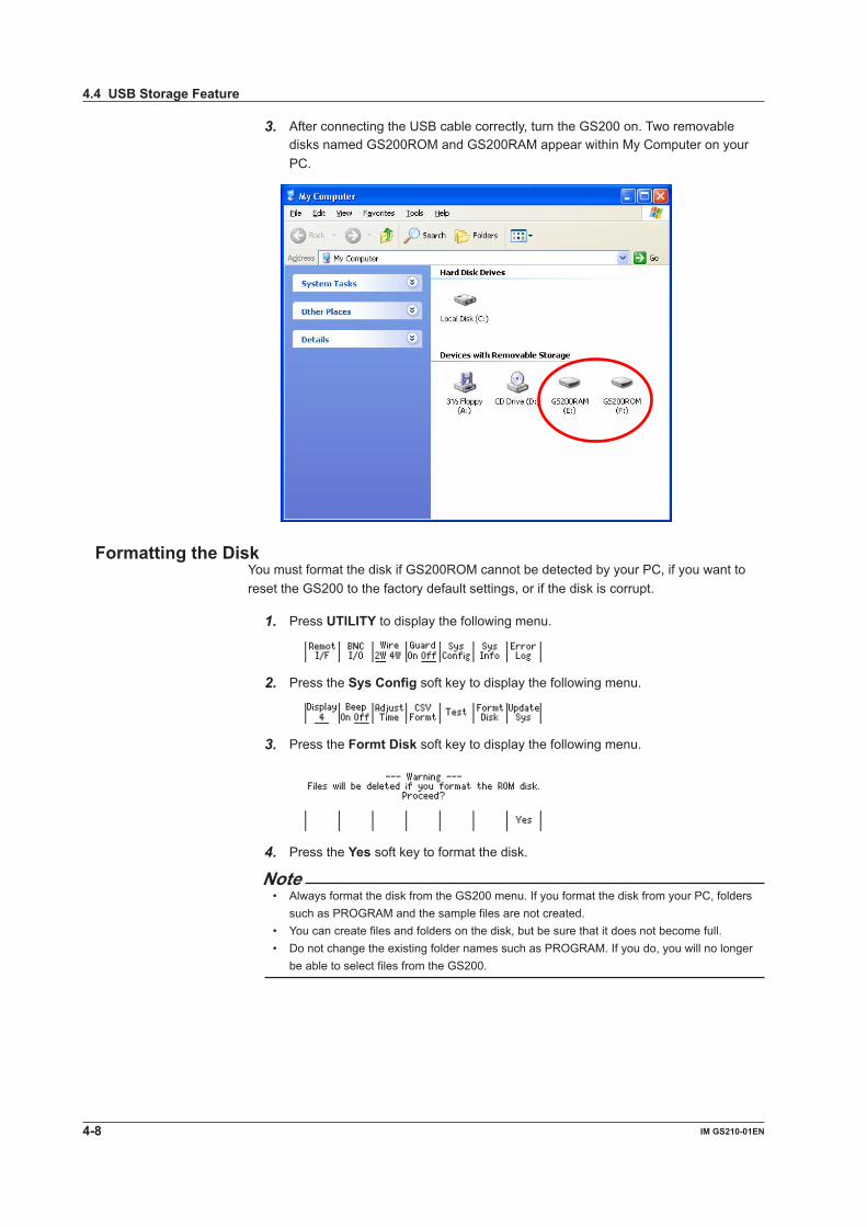
3. After connecting the USB cable correctly, turn the GS200 on. Two removable disks named GS200ROM and GS200RAM appear within My Computer on your PC.
Formatting the DiskYou must format the disk if GS200ROM cannot be detected by your PC, if you want to reset the GS200 to the factory default settings, or if the disk is corrupt.
1. Press UTILITY to display the following menu.
2. Press the Sys Config soft key to display the following menu.
3. Press the Formt Disk soft key to display the following menu.
4. Press the Yes soft key to format the disk.
Note• Always format the disk from the GS200 menu. If you format the disk from your PC, folders
such as PROGRAM and the sample files are not created.• You can create files and folders on the disk, but be sure that it does not become full.• Do not change the existing folder names such as PROGRAM. If you do, you will no longer
be able to select files from the GS200.
4.4 USB Storage Feature
4-8 IM GS210-01EN
3
2
1
4
5
6
7
8
9
10
11
12
13
14
15
App
Index
ExplanationUSB Storage Feature
For details on the USB storage feature, see section 2.8.
GS200ROMGS200ROM is a 4 MB non-volatile disk with preset folders for different purposes. Files are stored in the appropriate folders.• PROGRAM The PROGRAM folder stores program files that you can select when you want to
execute a program. When the GS200 is sent from the factory or when the disk is formatted, two sample
program files are stored in this folder.• SETUP The SETUP folder stores the GS200 panel setup data that is selected when settings
are loaded. When the GS200 is sent from the factory or when the disk is formatted, a sample
setup file is stored in this folder.
GS200RAMGS200RAM is a 16 MB RAM disk that is automatically formatted when the power is turned on. It is a volatile disk that is used to exchange files with a PC. The result file (Result.csv) is stored on this disk when the storage operation is carried out. Saved result files can be read from a PC.When you update the system firmware, system files are written to GS200RAM from your PC. For details, see section 14.5, “Updating the System Firmware.”
4.4 USB Storage Feature
4-9IM GS210-01EN
Com
mon Settings

5.1 Setting the Source Function
ProcedurePress V, mV, or mA.
ExplanationFor details on the source function, see section 2.3.
Display Example of Source Function
Voltage source (mV)
The relationship between the keys and the source function is as follows:• V key: Sets the source function to voltage and the source range to 1 V.• mV key: Sets the source function to voltage and the source range to 10 mV (the
circuit that produces the 10 mV range uses the voltage divider).• mA key: Sets the source function to current and the source range to 1 mA.
Note• When you change the source function from voltage (V or mV) to current (mA) or when you
change the source function from current (mA) to voltage (V or mV), the source level setting (the value) is retained. When you switch the source function, output is turned off.
• When you switch the voltage source function between mV and V, the source level is retained if it is within the range determined by the new source range. However, the fractional part of the source level that is outside of the range determined by the new source range is discarded. If the output was on before the voltage source function was changed, it remains on. If the source level is outside of the range determined by the new source range, the source level is set to 0.
<<Corresponding Command Mnemonic>>:SOURce:FUNCtion VOLTage|CURRent
Chapter 5 Source
5-1IM GS210-01EN
Source
3
2
1
4
5
6
7
8
9
10
11
12
13
14
15
App
Index
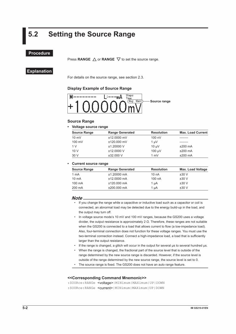
5.2 Setting the Source Range
ProcedurePress RANGE or RANGE to set the source range.
ExplanationFor details on the source range, see section 2.3.
Display Example of Source Range
Source range
Source Range• Voltage source range
Source Range Range Generated Resolution Max. Load Current10 mV ±12.0000 mV 100 nV --------100 mV ±120.000 mV 1 µV --------1 V ±1.20000 V 10 µV ±200 mA10 V ±12.0000 V 100 µV ±200 mA30 V ±32.000 V 1 mV ±200 mA
• Current source rangeSource Range Range Generated Resolution Max. Load Voltage1 mA ±1.20000 mA 10 nA ±30 V10 mA ±12.0000 mA 100 nA ±30 V100 mA ±120.000 mA 1 µA ±30 V200 mA ±200.000 mA 1 µA ±30 V
Note• If you change the range while a capacitive or inductive load such as a capacitor or coil is
connected, an abnormal load may be detected due to the energy build-up in the load, and the output may turn off.
• In voltage source mode’s 10 mV and 100 mV ranges, because the GS200 uses a voltage divider, the output resistance is approximately 2 Ω. Therefore, these ranges are not suitable when the GS200 is connected to a load that allows current to flow (a low-impedance load). Also, four-terminal connection does not function for these voltage ranges. You must use the two-terminal connection instead. Connect a high-impedance load, a load that is sufficiently larger than the output resistance.
• If the range is changed, a glitch will occur in the output for several µs to several hundred µs.• When the range is changed, the fractional part of the source level that is outside of the
range determined by the new source range is discarded. However, if the source level is outside of the range determined by the new source range, the source level is set to 0.
• The source range is fixed. The GS200 does not have an auto range feature.
<<Corresponding Command Mnemonic>>:SOURce:RANGe <voltage>|MINimum|MAXimum|UP|DOWN:SOURce:RANGe <current>|MINimum|MAXimum|UP|DOWN
5-2 IM GS210-01EN
5.3 Setting the Source Level
ProcedureIn up/down key mode, press the and keys to set the source level. In keypad mode, press NUM LOCK + or to set the source level.
Note• You can also change the source level when output is on.• If you enter a source level that exceeds the specified range, a beep sound (see section 9.4,
“Turning the Beep Sound On and Off”) is generated (only if the beep sound is on).
ExplanationRange of the Source LevelSee the Range Generated column in the tables under Source Range in section 5.2, “Setting the Source Range.”
When you enter the source level in keypad mode, the appropriate source range is applied for the specified source level, as shown in the table below.
Key SettingsV The source function is set to voltage, and the source range is set to the most
appropriate range greater than or equal to 1 V.mV The source function is set to voltage, and the source range is set to the most
appropriate range (the circuit that produces the most appropriate range uses the voltage divider).
mA The source function is set to current, and the source range is set to the most appropriate range.
ENTER The source function and source range do not change.
NoteBecause an output capacitance of approximately 500 pF exists between the GS200’s OUTPUT Hi and OUTPUT Lo terminals:• If the load changes drastically such as when a short circuit occurs in voltage source mode, a
large transient discharge current is generated from the output capacitance.• If a voltage source (such as a power supply, amplifier, or signal generator) is connected as a
load, the load voltage source may be unstable due to the output capacitance.
<<Corresponding Command Mnemonic>>:SOURce:LEVel[:FIX] <voltage>|MINimum|MAXimum:SOURce:LEVel[:FIX] <current>|MINimum|MAXimum:SOURce:LEVel:AUTO <voltage>|MINimum|MAXimum:SOURce:LEVel:AUTO <current>|MINimum|MAXimum
5-3IM GS210-01EN
Source
3
2
1
4
5
6
7
8
9
10
11
12
13
14
15
App
Index

5.4 Setting the Limiter
Procedure1. Press LIMIT to display the limiter setup screen.
Example of setting the current limiter in voltage source mode
2. In up/down key mode, press the and keys to set the limit. In keypad mode, press NUM LOCK + or to set the limit.
ExplanationFor details on the limiter, see section 2.3.
Setting LimitsIn voltage source mode, the current limiter is enabled. In current source mode, the voltage limiter is enabled.When you set the limiter, a high limit and a low limit are set. The absolute value of these limits is the same, but their polarities are different. Example High limit: +200 mA Low limit: –200 mA
Limiter Range Resolution Enabled WhenCurrent limiter 1 mA to 200 mA 1 mA Voltage is being generated.Voltage limiter 1 V to 30 V 1 V Current is being generated.
When the source range is set to 10 mV or 100 mV, the limit is fixed to 200 mA (you cannot change this value). In this situation, the limit displays “---mA,” as shown in the following figure.
Display When a Limiter Is ActivatedWhen the high limiter is activated: When the low limiter is activated:
High limiter display example:
<<Corresponding Command Mnemonic>>:SOURce:PROTection:VOLTage <voltage>|MINimum|MAXimum:SOURce:PROTection:CURRent <current>|MINimum|MAXimum
5-4 IM GS210-01EN

5.5 Turning the Output On and Off
ProcedurePress OUTPUT. The OUTPUT key illuminates while the output is on.If you press OUTPUT while the output is on, the output will stop. When the output stops, the OUTPUT key turns off.
ExplanationTurning the Output On and OffThe output relay switches between on and off.
Note• When the output relay operates, the source level changes as follows.
• When Output Is Turned On The output relay turns on with the source level set to zero. After the output relay
switches, the source level is changed to the specified source level.• When Output is Turned Off The source level is set to zero, and then the output relay is turned off.
• When output is off, you cannot execute programs (see chapter 6) or perform measurements (see chapter 7).
• At the 10 V and 30 V ranges, when you turn the output on, an internal process to reduce the zero-point error takes place for 0.4 second. However, the internal process does not take place in the following situations.• If the output is turned on within 1 second after it is turned off.• If output is turned on within 5 minutes after the power is turned on.
The Relationship between Capacitive and Inductive Loads and Output• When a capacitive load is connected to the GS200 in voltage source mode, the
response time may become longer. Also, if the load has a capacitance of 10 µF or greater, oscillation may occur.
• If you change the output settings drastically under the usage conditions listed above, the limiter may be activated due to the inrush current.
• When an inductive load is connected to the GS200 in current source mode, the response time may become longer. Also, if the load has an inductance of 1 mH or greater, oscillation may occur.
<<Corresponding Command Mnemonic>>:OUTPut[:STATe] 1|0|ON|OFF
5-5IM GS210-01EN
Source
3
2
1
4
5
6
7
8
9
10
11
12
13
14
15
App
Index

6.1 Turning Program Repetition Mode On and Off
Procedure1. Press PROGRAM to display the following menu.
2. Press the Repeat soft key to select On or Off.If you select On, the REPEAT indicator illuminates.If you select Off, the REPEAT indicator turns off.
ExplanationProgram Repetition ModeIf you set Repeat to On, when the final step in the program completes, the GS200 will return to the first step in the program and repeat it. You cannot set the number of times that the program is repeated.
<<Corresponding Command Mnemonic>>:PROGram:REPeat[:STATe] 1|0|ON|OFF
Chapter 6 Programs
6-1IM GS210-01EN
Programs
3
2
1
4
5
6
7
8
9
10
11
12
13
14
15
App
Index
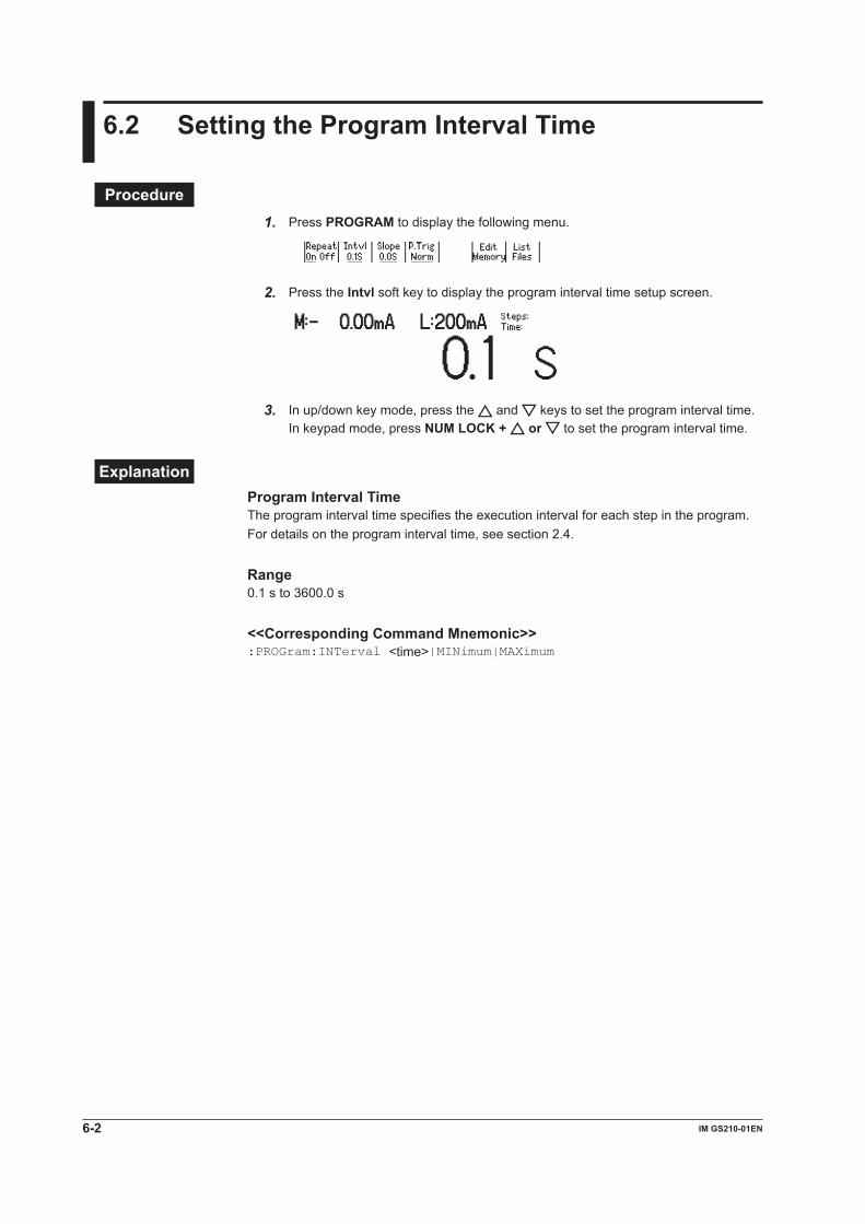
6.2 Setting the Program Interval Time
Procedure1. Press PROGRAM to display the following menu.
2. Press the Intvl soft key to display the program interval time setup screen.
3. In up/down key mode, press the and keys to set the program interval time. In keypad mode, press NUM LOCK + or to set the program interval time.
ExplanationProgram Interval TimeThe program interval time specifies the execution interval for each step in the program. For details on the program interval time, see section 2.4.
Range0.1 s to 3600.0 s
<<Corresponding Command Mnemonic>>:PROGram:INTerval <time>|MINimum|MAXimum
6-2 IM GS210-01EN
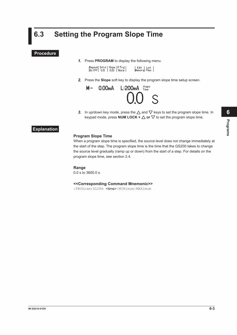
6.3 Setting the Program Slope Time
Procedure1. Press PROGRAM to display the following menu.
2. Press the Slope soft key to display the program slope time setup screen.
3. In up/down key mode, press the and keys to set the program slope time. In keypad mode, press NUM LOCK + or to set the program slope time.
ExplanationProgram Slope TimeWhen a program slope time is specified, the source level does not change immediately at the start of the step. The program slope time is the time that the GS200 takes to change the source level gradually (ramp up or down) from the start of a step. For details on the program slope time, see section 2.4.
Range0.0 s to 3600.0 s
<<Corresponding Command Mnemonic>>:PROGram:SLOPe <time>|MINimum|MAXimum
6-3IM GS210-01EN
Programs
3
2
1
4
5
6
7
8
9
10
11
12
13
14
15
App
Index

6.4 Setting the Program Trigger (/MON option)
Procedure1. Press PROGRAM to display the following menu.
2. Press the P.Trig soft key to display the following menu.
3. Press the Norm or M.End soft key to set the program trigger.
ExplanationOn models with the /MON option, you can select Norm or M.End for the program trigger. On models without the /MON option, the program trigger is fixed to Norm, and this menu is not displayed.
• Norm (Normal) You can use the RUN, STEP, and HOLD keys and external triggers to control the
program execution. The program interval time specifies the execution interval for each step in the program.
• M.End (Measurement end; only on models with the /MON option) When you turn output on, the program executes automatically. If you set the program
trigger to M.End, and the measurement trigger to Ready (source change completion; see section 7.4), the program executes the source and measurement operations of each step in the minimum time required. The RUN, STEP, and HOLD keys and external triggers are disabled. Additionally, the program interval setting is ignored.
<<Corresponding Command Mnemonic>>:PROGram:TRIGger NORMal|MEND
6-4 IM GS210-01EN

6.5 Creating and Editing Programs
ProcedureCreating and Editing Programs from the GS200
1. Press PROGRAM to display the following menu.
2. Press the Edit Memory soft key to display the program editing screen.
Source range
Number of the step that is currently being edited
Source function Source level
Displayed when this is a new step
Setting the Source Function3. Press V, mV, or mA.
Setting the Source Range4. Press RANGE or RANGE to set the source range.
Setting the Source Level5. In up/down key mode, press the and keys to set the source level. In keypad
mode, press NUM LOCK + or to set the source level.
Confirming the Settings6. Press ENTER to confirm the settings for that step and increase the number of the
step that is being edited by one.
NoteIf the number of the step that is currently being edited is 10000, this number is not increased.
7. Repeat steps 3 to 6 to edit all the steps in the program.
Re-Editing Selected Steps in the Program8. Press STEP ( ) or RUN ( ) to select the step that you want to edit.
9. Repeat steps 3 to 6 to edit all the steps in the program.
6-5IM GS210-01EN
Programs
3
2
1
4
5
6
7
8
9
10
11
12
13
14
15
App
Index
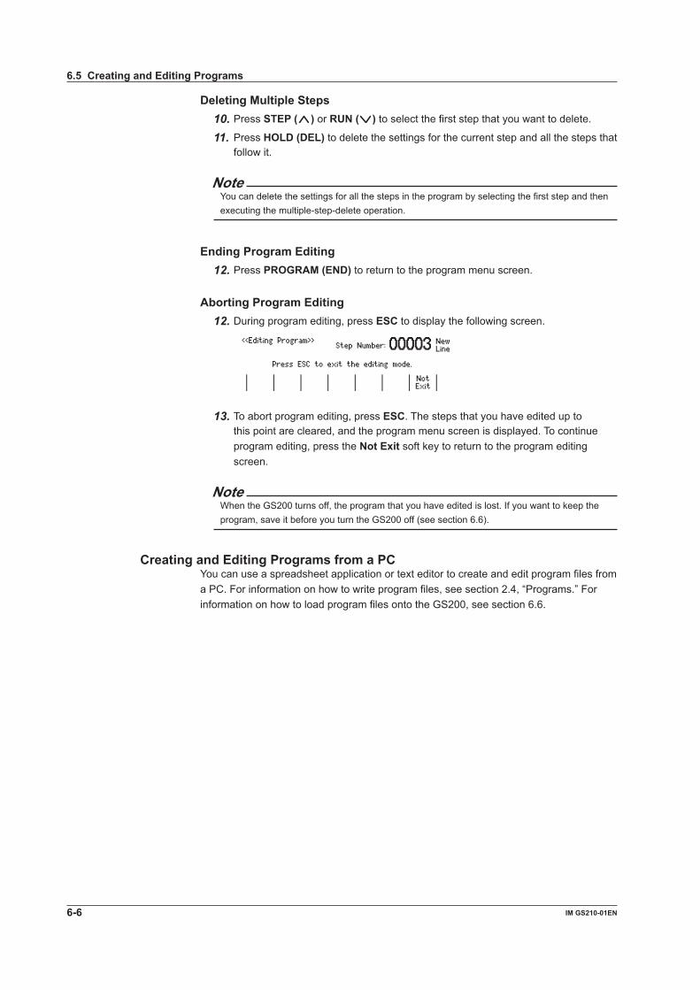
Deleting Multiple Steps10. Press STEP ( ) or RUN ( ) to select the first step that you want to delete.
11. Press HOLD (DEL) to delete the settings for the current step and all the steps that follow it.
NoteYou can delete the settings for all the steps in the program by selecting the first step and then executing the multiple-step-delete operation.
Ending Program Editing12. Press PROGRAM (END) to return to the program menu screen.
Aborting Program Editing12. During program editing, press ESC to display the following screen.
13. To abort program editing, press ESC. The steps that you have edited up to this point are cleared, and the program menu screen is displayed. To continue program editing, press the Not Exit soft key to return to the program editing screen.
NoteWhen the GS200 turns off, the program that you have edited is lost. If you want to keep the program, save it before you turn the GS200 off (see section 6.6).
Creating and Editing Programs from a PCYou can use a spreadsheet application or text editor to create and edit program files from a PC. For information on how to write program files, see section 2.4, “Programs.” For information on how to load program files onto the GS200, see section 6.6.
6.5 Creating and Editing Programs
6-6 IM GS210-01EN
ExplanationYou can create and edit programs from:• The GS200.• A PC.
Creating and Editing Programs from the GS200
The Program Editing ScreenNew LineThis is displayed when you are currently editing a new step (the step after the last step). You can add new steps to the program by editing this step.
Creating a New ProgramWhen you create a new program, the initial source level value is 0 V or 0 mA.
Editing ProgramsWhen you create a program on the GS200, the program is displayed on the screen. When you load an existing program onto the GS200, the program is displayed on the screen.
Creating and Editing Programs from a PCNumber of StepsA program can contain up to 10000 steps. If you use a PC to create a program that contains more than 10000 steps, the GS200 will only load the first 10000 steps.
<<Corresponding Command Mnemonic>>:PROGram:EDIT:STARt
:PROGram:EDIT:END
:SOURce:FUNCtion VOLTage|CURRent
:SOURce:RANGe <voltage>|MINimum|MAXimum|UP|DOWN
:SOURce:RANGe <current>|MINimum|MAXimum|UP|DOWN
:SOURce:LEVel[:FIX] <voltage>|MINimum|MAXimum
:SOURce:LEVel[:FIX] <current>|MINimum|MAXimum
:SOURce:LEVel:AUTO <voltage>|MINimum|MAXimum
:SOURce:LEVel:AUTO <current>|MINimum|MAXimum
6.5 Creating and Editing Programs
6-7IM GS210-01EN
Programs
3
2
1
4
5
6
7
8
9
10
11
12
13
14
15
App
Index

6.6 Saving and Loading Programs
Procedure1. Press PROGRAM to display the following menu.
2. Press the List Files soft key to display the currently saved files and the following menu.
Saving Programs3. Press the Save File soft key to display the following menu.
Using a Soft Key to Directly Specify the Program from Pgrm01 to Pgrm04
4. Press a soft key from Pgrm01 to Pgrm04 to save the corresponding program. While the program is being saved, the soft key that you pressed is highlighted.When the file save operation completes, an asterisk is displayed to the left of the name of the file that was saved. Return to the menu that was shown in step 2.
Using the File List to Specify the File to Overwrite
4. Press the soft key to move the cursor (underline) up and down and select the file that you want to overwrite.
5. Press the Over Write soft key. When a file is being saved, “Over Write” is highlighted.When the file save operation completes, an asterisk is displayed to the left of the name of the file that was saved. Return to the menu that was shown in step 2.
6-8 IM GS210-01EN

Loading Files That Were Created on a PC onto the GS2001. Follow the procedures listed in section 4.4, “Setting the USB Storage Feature”
and “How to Connect the USB Cable” to connect the GS200 and a PC using a USB cable.
2. Copy the program that you created on the PC to the PROGRAM folder on the GS200’s GS200ROM disk.
Loading Programs1. Press PROGRAM to display the following menu.
2. Press the List Files soft key to display the currently saved files and the following menu.
3. Press the soft key to move the cursor (underline) up and down and select the file that you want to load.
4. Press the Load File soft key.The program file is loaded. An asterisk is displayed to the left of the file that was loaded.
Deleting Programs3. Press the soft key to move the cursor (underline) up and down and select the
file that you want to delete.
4. Press the Delete File soft key to display the following menu.
6.6 Saving and Loading Programs
6-9IM GS210-01EN
Programs
3
2
1
4
5
6
7
8
9
10
11
12
13
14
15
App
Index

5. To delete the file, press the Yes soft key.The file is deleted.
Displaying Program Contents3. Press the soft key to move the cursor (underline) up and down and select the
file that you want to display the contents of.
4. Press the View File soft key.The contents of the program are displayed.
5. Press RANGE or RANGE to scroll the display.
ExplanationProgram ListThe program that was last loaded has an asterisk displayed to the left of its file name.
Saving ProgramsPrograms are saved as program files (Prgm01.csv to Prgm04.csv) in the GS200ROM’s PROGRAM folder. If you save a program number that already exists, the existing program file is overwritten.
Note• Program files are text files. You can change their contents from a PC.• You can change the names of the files that are stored in the GS200ROM’s PROGRAM
folder from a PC.
Loading Files That Were Created on a PC onto the GS200You can use the USB storage feature to load program files that were created on a PC onto the GS200.
Loading ProgramsYou can load a saved program file to restore the program.
NoteIf the GS200 cannot read program files correctly, its CSV-format settings may not match the program files. Check the CSV-format settings (see section 9.5).
6.6 Saving and Loading Programs
6-10 IM GS210-01EN

Deleting ProgramsYou can delete program files that you no longer need.
Displaying Program ContentsYou can check the contents of program files.
<<Corresponding Command Mnemonic>>:PROGram:SAVE <character string>:PROGram:LOAD <character string>:PROGram:DELete <character string>:PROGram:CATalog?
:PROGram:MEMory <character string>|<block data>:PROGram:DEFine <character string>,<character string>|<block data>
6.6 Saving and Loading Programs
6-11IM GS210-01EN
Programs
3
2
1
4
5
6
7
8
9
10
11
12
13
14
15
App
Index
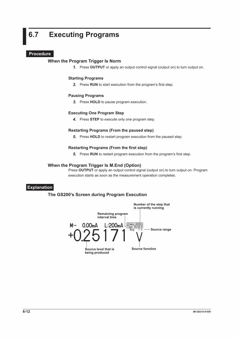
6.7 Executing Programs
ProcedureWhen the Program Trigger Is Norm
1. Press OUTPUT or apply an output control signal (output on) to turn output on.
Starting Programs2. Press RUN to start execution from the program’s first step.
Pausing Programs3. Press HOLD to pause program execution.
Executing One Program Step4. Press STEP to execute only one program step.
Restarting Programs (From the paused step)5. Press HOLD to restart program execution from the paused step.
Restarting Programs (From the first step)5. Press RUN to restart program execution from the program’s first step.
When the Program Trigger Is M.End (Option)Press OUTPUT or apply an output control signal (output on) to turn output on. Program execution starts as soon as the measurement operation completes.
ExplanationThe GS200’s Screen during Program Execution
Source range
Number of the step that is currently running
Source function Source level that is being produced
Remaining program interval time
6-12 IM GS210-01EN
Changing SettingsWhile a program is executing, you can:• Turn output off.• Turn program repetition on and off.• Turn measurement on and off.• Turn NULL on and off.• Turn storage on and off.• Turn storage file creation on and off.• Turn the display on and off.
Executing ProgramsFor details on executing programs, see section 2.4.
Operations When the Program Trigger Is Set to NormYou can use the RUN, STEP, and HOLD keys and external triggers to control the program execution. The program interval time specifies the execution interval for each step in the program.If you press the RUN or STEP key during program execution, a sampling error occurs.
Operations When the Program Trigger Is Set to M.End (Option)When measurement completes, the GS200 proceeds to the next step in the program and changes the source level. If you set the program trigger to measurement end (M.End), and the measurement trigger to source change completion (Ready), the program executes the source and measurement operations of each step in the minimum time required.The RUN, STEP, and HOLD keys and external triggers are disabled. Additionally, the program interval setting is ignored.
NoteIf you use a PC to copy or delete files on the GS200 during program execution, the timing of the program operations may be affected.
<<Corresponding Command Mnemonic>>:PROGram:RUN
:PROGram:STEP
:PROGram:HOLD
:PROGram:PAUSe
:PROGram:CONTinue
:PROGram:COUNt <integer>|MINimum|MAXimum
6.7 Executing Programs
6-13IM GS210-01EN
Programs
3
2
1
4
5
6
7
8
9
10
11
12
13
14
15
App
Index

7.1 Turning Measurement On and Off
Procedure1. Press MEASURE to display the following menu.
2. Press the Meas soft key to select On or Off.
ExplanationOn (Measurement on)When the source function is set to voltage, the GS200 measures current. When the source function is set to current, the GS200 measures voltage. The GS200 performs measurement when output is on. The measured value is displayed in the upper-left section of the screen.
Measured value
When the source range is set to 10 mV or 100 mV, you cannot use the measurement feature. The measured value area displays “Cannot measure in mV source range.”
If the measured value is greater than the positive limit of the measurement range, the measured value area displays “+OVER.” If the measured value is lower than the negative limit of the measurement range, the measured value area displays “–OVER.”
Off (Measurement off)Measurement is not performed. The measured value area displays “Off.”
Note• When you turn measurements on, noise may be superimposed on the source output
depending on the operation of the GS200 internal measurement circuit. To reduce noise in the source output, turn measurements off.
• When measurements are being performed, the timing of measurements may be affected if you:• Change a setting that is saved when the GS200 turns off (see appendix 1).• Copy or delete files from a PC.
• On GS200s without the measurement (monitoring; /MON) option, nothing is displayed in the measured value area.
<<Corresponding Command Mnemonic>>:SENSe[:STATe] 1|0|ON|OFF
Chapter 7 Measurement (Option)
7-1IM GS210-01EN
Measurem
ent (Option)
3
2
1
4
5
6
7
8
9
10
11
12
13
14
15
App
Index

7.2 Setting the Integration Time
Procedure1. Press MEASURE to display the following menu.
2. Press the Meas Config soft key to display the following menu.
3. Press the Integ soft key to display the integration time setup screen.
4. In up/down key mode, press the and keys to set the integration time. In keypad mode, press NUM LOCK + or to set the integration time.
ExplanationIntegration TimeThe stability of measured values increases as the integration time is set longer. However, the measurement time will be longer. Set the integration time to an integer multiple of the power line cycle (nPLC). The line frequency is measured automatically inside the GS200. You can use the communication command “:SYSTem:LFRequency?” to check the measured line frequency.
Range1 PLC to 25 PLC (PLC stands for Power Line Cycles. One PLC is equivalent to one period of the power source signal.)
NoteIn one measurement operation, the output value and the zero reference value are both measured. Therefore, the time for one measurement operation is: ((measurement delay + integration time) × 2) + software processing time (see section 2.5). For example, in an environment where the power supply frequency is 50 Hz (1 PLC = 20 ms), if the measurement delay is set to 0 ms and the integration time is set to 25 PLC (500 ms), the time required for one measurement is the sum of approximately 1 second and the software processing time. Software processing time is less than 1 ms.
<<Corresponding Command Mnemonic>>:SENSe:NPLC <integer>|MINimum|MAXimum
7-2 IM GS210-01EN

7.3 Setting the Measurement Delay
Procedure1. Press MEASURE to display the following menu.
2. Press the Meas Config soft key to display the following menu.
3. Press the Delay soft key to display the measurement delay setup screen.
4. In up/down key mode, press the and keys to set the measurement delay. In keypad mode, press NUM LOCK + or to set the measurement delay.
ExplanationMeasurement DelayThe measurement delay is the time that the GS200 waits from when the measurement trigger is generated until measurement actually starts. Set this delay if you want to insert a delay after the source level is changed until the measurement is actually started to allow the DUT to stabilize. For details on the measurement delay, see section 2.5.
Range0 ms to 999999 ms
NoteThe time from when the source trigger is applied to when the source level stabilizes varies depending on the load, source range, and limiter level. When you adjust the length of the measurement delay, keep these in mind in addition to the time needed for the DUT to stabilize after the source level is applied.
<<Corresponding Command Mnemonic>>:SENSe:DELay <time>|MINimum|MAXimum
7-3IM GS210-01EN
Measurem
ent (Option)
3
2
1
4
5
6
7
8
9
10
11
12
13
14
15
App
Index

7.4 Selecting the Measurement Trigger
Procedure1. Press MEASURE to display the following menu.
2. Press the Meas Config soft key to display the following menu.
3. Press the soft key that corresponds to the measurement trigger that you want to use.
ExplanationFor details on measurement triggers, see section 2.6.
The measurement trigger is a signal source that is used to start measurement. You can set the trigger source to one of the settings below.Timer (see “Measurement Timer” in section 7.5)Immed: Measurement completion (immediate)Ready: Source change completionComm: Communication commands
NoteA sampling error occurs if a new measurement trigger is generated while a measurement is in progress.
<<Corresponding Command Mnemonic>>:SENSe:TRIGger READy|TIMer|COMMunicate|IMMediate
7-4 IM GS210-01EN
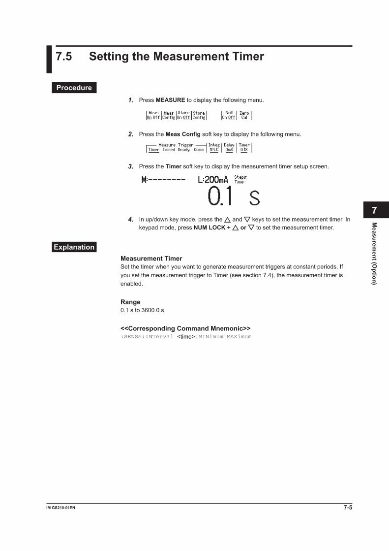
7.5 Setting the Measurement Timer
Procedure1. Press MEASURE to display the following menu.
2. Press the Meas Config soft key to display the following menu.
3. Press the Timer soft key to display the measurement timer setup screen.
4. In up/down key mode, press the and keys to set the measurement timer. In keypad mode, press NUM LOCK + or to set the measurement timer.
ExplanationMeasurement TimerSet the timer when you want to generate measurement triggers at constant periods. If you set the measurement trigger to Timer (see section 7.4), the measurement timer is enabled.
Range0.1 s to 3600.0 s
<<Corresponding Command Mnemonic>>:SENSe:INTerval <time>|MINimum|MAXimum
7-5IM GS210-01EN
Measurem
ent (Option)
3
2
1
4
5
6
7
8
9
10
11
12
13
14
15
App
Index
7.6 Turning the NULL Computation On and Off
Procedure1. Press MEASURE to display the following menu.
2. Press the Null soft key to select On or Off.
ExplanationNULL ComputationWhen you turn NULL computation on, the NULL value will be set to the next measured value. While NULL computation is on, the measured result is calculated by subtracting the NULL value from the measured value.
<<Corresponding Command Mnemonic>>:SENSe:NULL[:STATe] 1|0|ON|OFF
7-6 IM GS210-01EN

7.7 Zero Calibration (Zero reference measurement)
Procedure1. Press MEASURE to display the following menu.
2. Press the Zero Cal soft key to execute the zero reference measurement.While the zero reference is being measured, the Zero Cal soft key is highlighted.
ExplanationFor details on the zero calibration feature, see section 2.5.
Zero CalibrationIf zero calibration is executed, output is automatically turned off, the zero reference is measured, and the zero reference is applied to subsequent measured results. The zero point may change due to the passage of time, the GS200 being in an environment where the temperature changes drastically, or due to other factors. By executing zero calibration, the zero point is calibrated, and this enables the GS200 to generate more accurate output measurement.
<<Corresponding Command Mnemonic>>:SENSe:ZERO:EXECute
7-7IM GS210-01EN
Measurem
ent (Option)
3
2
1
4
5
6
7
8
9
10
11
12
13
14
15
App
Index

7.8 Storing Measured Results
Procedure1. Press MEASURE to display the following menu.
2. Press the Store Config soft key to display the following menu.
Setting the Storage Count3. Press the Count soft key to display the storage count setup screen.
4. In up/down key mode, press the and keys to set the storage count. In keypad mode, press NUM LOCK + or to set the storage count.
Turning the Result File (Result.csv) Generation Feature On and Off3. Press the File soft key to select On or Off.
Starting the Storage Operation2. Press the Store soft key to start the storage operation. The STORE indicator
illuminates.
Forcibly Stopping the Storage Operation3. When the storage operation is in progress, press the Store soft key once more to
forcibly stop the storage operation. The STORE indicator turns off.
7-8 IM GS210-01EN

ExplanationFor details on the storage feature, see section 2.5.
Storage CountThe storage count specifies the number of measured results that are stored.Range: 1 to 10000
Turning the Result File (Result.csv) Generation Feature On and OffIf you turn the result file generation feature on, when the storage operation finishes, the GS200 stores a result file that contains a list of all the contents of storage memory. The result file (Result.csv) is a text file in CSV format. It is stored on the GS200RAM disk. If the number of measurements that are performed exceeds the storage count, this file only contains results from as many measurements as the storage count specifies.
Note• GS200RAM is a volatile-memory disk. The files that are stored on it are lost when you turn
off the GS200. If there are result files that you want to retain, move them to the connected PC before you turn off the GS200.
• If the measured value is greater than the positive limit of the measurement range, “+INF” is written to the measured value section of the result file. If the measured value is lower than the negative limit of the measurement range, “–INF” is written to the measured value section of the result file.
Stopping the Storage OperationThe storage operation stops automatically when the specified number of results have been stored.
Forcibly Stopping the Storage OperationWhen the storage operation is in progress, press the Store soft key to forcibly stop the storage operation. The results that have been stored up to this point are stored on the GS200RAM disk as a result file.
<<Corresponding Command Mnemonic>>:TRACe[:STATe] 1|0|ON|OFF
:TRACe:FILE:CREate 1|0|ON|OFF
:TRACe:POINts <integer>|MINimum|MAXimum
7.8 Storing Measured Results
7-9IM GS210-01EN
Measurem
ent (Option)
3
2
1
4
5
6
7
8
9
10
11
12
13
14
15
App
Index

7.9 Performing Statistical Computations on Measured Values (Recall)
Procedure1. Press MEASURE to display the following menu.
2. Press the Store Config soft key to display the following menu.
3. Press the Recall soft key to display statistical computations of the measured values that were most recently stored.
ExplanationFor details on the statistical computation feature, see section 2.5.
Statistical ComputationsThe following statistical computations are displayed. If no measured results have been stored, each computation displays “-----------.”
Maximum – minimum Mean value Standard deviation
Minimum value Maximum valueStorage count
<<Corresponding Command Mnemonic>>:TRACe:DATA:STATistics?
Using Communications to Load Stored ResultsYou can use the communication feature to read the storage result directly.
<<Corresponding Command Mnemonic>>:TRACe:ACTual?
:TRACe:DATA:FORMat ASCii|BINary
:TRACe:DATA:ENDian BIG|LITTle
:TRACe:DATA:READ? [TM|SF|SL|MF|ML]
7-10 IM GS210-01EN

8.1 Synchronous Operation Using the BNC I/O Terminals (IN and OUT)
Procedure1. Press UTILITY to display the following menu.
2. Press the BNC I/O soft key to display the following menu.
3. Set the BNC OUT terminal’s signal by selecting Trig, Output, or Ready on the BNC Out menu.
4. Set the BNC IN terminal’s signal by selecting Trig or Output on the BNC In menu.
ExplanationFor details on the BNC I/O terminals, see section 2.7.
The GS200 can transmit or receive the following signals through the BNC I/O terminals on the rear panel.• Output terminal (OUT)
Trig: The TrigBusy signal (see section 2.4) Output: An output signal (see section 5.5) Ready: The source change completion signal (see section 2.6)
• Input terminal (IN) Trig: The STEP trigger for program execution (see section 6.4) Output: An output signal
BNC I/O Terminals
Input terminal
Output terminal
IN OUT
Chapter 8 Synchronous Operation
8-1IM GS210-01EN
Synchronous Operation
3
2
1
4
5
6
7
8
9
10
11
12
13
14
15
App
Index
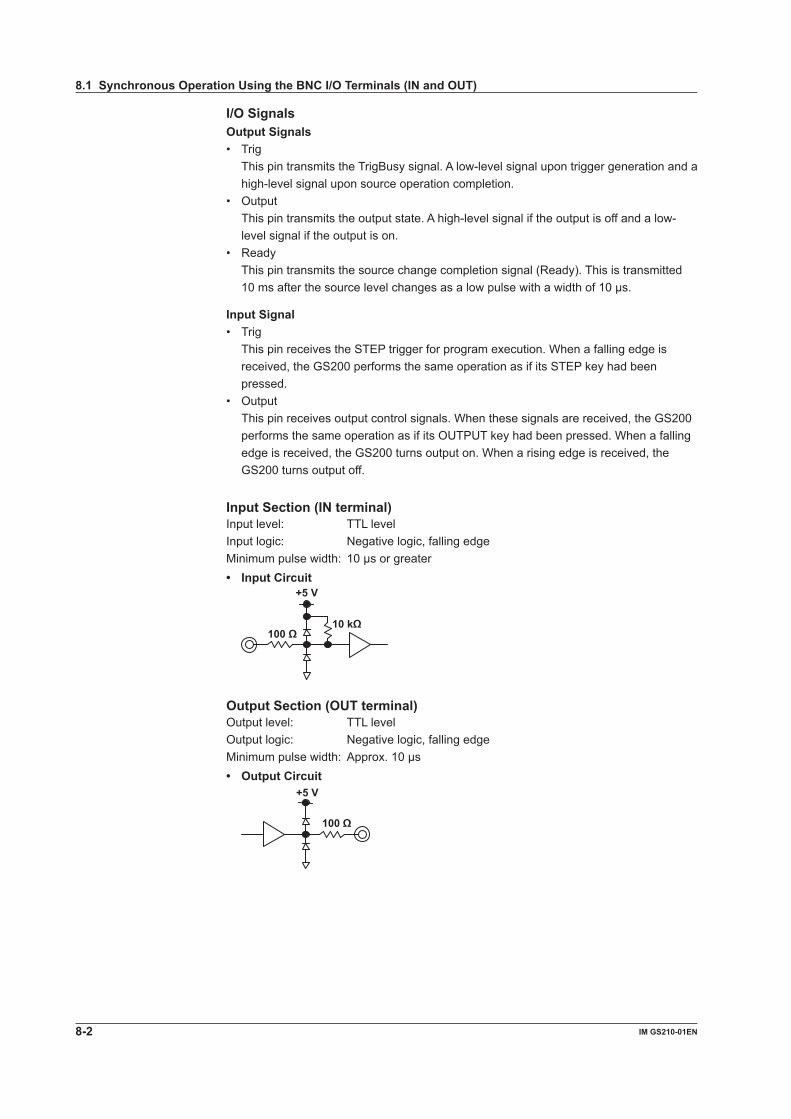
I/O SignalsOutput Signals• Trig This pin transmits the TrigBusy signal. A low-level signal upon trigger generation and a
high-level signal upon source operation completion.• Output This pin transmits the output state. A high-level signal if the output is off and a low-
level signal if the output is on.• Ready This pin transmits the source change completion signal (Ready). This is transmitted
10 ms after the source level changes as a low pulse with a width of 10 µs.
Input Signal• Trig This pin receives the STEP trigger for program execution. When a falling edge is
received, the GS200 performs the same operation as if its STEP key had been pressed.
• Output This pin receives output control signals. When these signals are received, the GS200
performs the same operation as if its OUTPUT key had been pressed. When a falling edge is received, the GS200 turns output on. When a rising edge is received, the GS200 turns output off.
Input Section (IN terminal)Input level: TTL levelInput logic: Negative logic, falling edgeMinimum pulse width: 10 µs or greater• Input Circuit
+5 V
10 kΩ100 Ω
Output Section (OUT terminal)Output level: TTL levelOutput logic: Negative logic, falling edgeMinimum pulse width: Approx. 10 µs• Output Circuit
+5 V
100 Ω
8.1 Synchronous Operation Using the BNC I/O Terminals (IN and OUT)
8-2 IM GS210-01EN

CAUTION• Only apply a voltage that is within the range of 0 V to 5 V to the input.• Do not short or apply external voltage to the output.
French
ATTENTION• Appliquer uniquement une tension comprise dans la plage de 0 V à 5 V à l’entrée.• Ne court-circuitez pas la sortie et n’appliquez par de tension externe à cette
dernière.
Using the BNC Terminals to Perform Synchronous Operation with Multiple GS200sYou can synchronize the output (turning on and off) and program execution of multiple GS200s by connecting their OUTPUT OUT and OUTPUT IN or TRIG OUT and TRIG IN signals.
Example of Synchronizing Program Execution
GS210
Master
IN OUT
GS210
Slave
Trig
IN OUT
GS210
Slave
IN OUT
Trig Trig
Note• The maximum delay from TRIG IN to TRIG OUT is less than or equal to 1 µs.• The maximum delay from OUTPUT IN to OUTPUT OUT is less than or equal to 20 ms.• If you are using both the RJ-11 connectors and BNC terminals, do not apply the same signal
to them at the same time. Doing so may cause errors.
8.1 Synchronous Operation Using the BNC I/O Terminals (IN and OUT)
8-3IM GS210-01EN
Synchronous Operation
3
2
1
4
5
6
7
8
9
10
11
12
13
14
15
App
Index

Using the BNC Terminals to Perform Synchronous Operation with the GS200 and Other DevicesYou can control the GS200’s output (turning on and off) and program execution by applying OUTPUT IN or TRIG IN signals that are transmitted from a device such as a controller.Additionally, if you connect the GS200’s READY OUT signal to the measurement trigger input of an external DMM, you can start measurements when the output source stabilizes.
Controller
Source change
GS210
IN OUT
DMM Measurement trigger
Ready
Trig
DUT
Current source
Voltage measurement
<<Corresponding Command Mnemonic>>:ROUTe:BNCO TRIGger|OUTPut|READy
:ROUTe:BNCI TRIGger|OUTPut
8.1 Synchronous Operation Using the BNC I/O Terminals (IN and OUT)
8-4 IM GS210-01EN

8.2 Using the RJ-11 Connectors (SYNC IN and SYNC OUT) to Perform Synchronous Operation
If you connect the I/O terminals for synchronous operation on the rear panel of multiple GS200s, you can operate them in sync.I/O Terminals for Synchronous OperationThere are two RJ-11 connectors, one for input and another for output.
6NC
5NC
4GND
3TRIG
IN
2NC
1OUTPUT
IN
SYNC IN6*
5READYOUT
4GND
3TRIGOUT
2NC
1OUTPUTOUT
SYNC OUT
IN OUTSYNC
Synchronous input
Synchronous output
Pinout
Pin No. SYNC IN (Synchronous Input) SYNC OUT (Synchronous Output)1 OUTPUT IN (output control input) OUTPUT OUT (output control output)2 NC NC3 TRIG IN (trigger input) TRIG OUT (trigger output)4 GND GND5 NC READY OUT (source change completion output)6 NC *
* This pin is used for servicing the GS200. Do not use it.
Connecting the GS200sUse a synchronous operation cable (sold separately; 758960; 6-wire) to connect two GS200s. You can make synchronous operation possible by connecting the synchronous operation output of a higher level GS200 to the synchronous operation input of a lower level GS200.
NoteDo not use other commercially available cables. Only use the synchronous operation cable described above to connect GS200s.
8-5IM GS210-01EN
Synchronous Operation
3
2
1
4
5
6
7
8
9
10
11
12
13
14
15
App
Index

SignalsOUTPUT IN (Output control input)This pin receives output control signals. When these signals are received, the GS200 performs the same operation as if its OUTPUT key had been pressed. When a falling edge is received, the GS200 turns output on. When a rising edge is received, the GS200 turns output off.
OUTPUT OUT (Output control output)This pin transmits the output state. A high-level signal if the output is off and a low-level signal if the output is on.
TRIG IN (Trigger input)This pin receives the STEP trigger for program execution. When a falling edge is received, the GS200 performs the same operation as if its STEP key had been pressed.
TRIG OUT (Trigger output)This pin transmits the TrigBusy signal. A low-level signal upon trigger generation and a high-level signal upon source operation completion.
READY OUT (Source change completion output)This pin transmits the source change completion signal (Ready). This is transmitted 10 ms after the source level changes as a low pulse with a width of 10 µs.
10 µs
Note
GS210
Master
SYNC IN OUT
GS210
Slave
SYNC IN OUT
GS210
Slave
SYNC IN OUT
The maximum delay from TRIG IN to TRIG OUT is less than or equal to 1 µs.The maximum delay from OUTPUT IN to OUTPUT OUT is less than or equal to 20 ms.
8.2 Using the RJ-11 Connectors (SYNC IN and SYNC OUT) to Perform Synchronous Operation
8-6 IM GS210-01EN

9.1 Initializing Setup Data
Procedure1. Press SETUP to display the currently saved files and the following menu.
2. Press the Init Setup soft key to initialize the setup data.While the setup data is being initialized, the Init Setup soft key is highlighted.
ExplanationWhen you initialize the setup data, the GS200 is returned to its factory default settings. For information on the factory default settings, see appendix 1, “Factory Default Settings.”
<<Corresponding Command Mnemonic>>*RST
Chapter 9 Other Features
9-1IM GS210-01EN
Other Features
3
2
1
4
5
6
7
8
9
10
11
12
13
14
15
App
Index
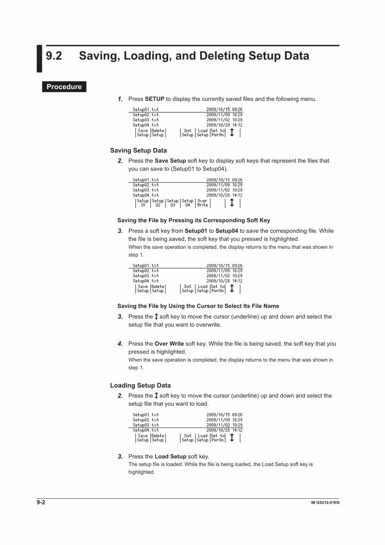
9.2 Saving, Loading, and Deleting Setup Data
Procedure1. Press SETUP to display the currently saved files and the following menu.
Saving Setup Data2. Press the Save Setup soft key to display soft keys that represent the files that
you can save to (Setup01 to Setup04).
Saving the File by Pressing its Corresponding Soft Key
3. Press a soft key from Setup01 to Setup04 to save the corresponding file. While the file is being saved, the soft key that you pressed is highlighted.When the save operation is completed, the display returns to the menu that was shown in step 1.
Saving the File by Using the Cursor to Select Its File Name
3. Press the soft key to move the cursor (underline) up and down and select the setup file that you want to overwrite.
4. Press the Over Write soft key. While the file is being saved, the soft key that you pressed is highlighted.When the save operation is completed, the display returns to the menu that was shown in step 1.
Loading Setup Data2. Press the soft key to move the cursor (underline) up and down and select the
setup file that you want to load.
3. Press the Load Setup soft key.The setup file is loaded. While the file is being loaded, the Load Setup soft key is highlighted.
9-2 IM GS210-01EN
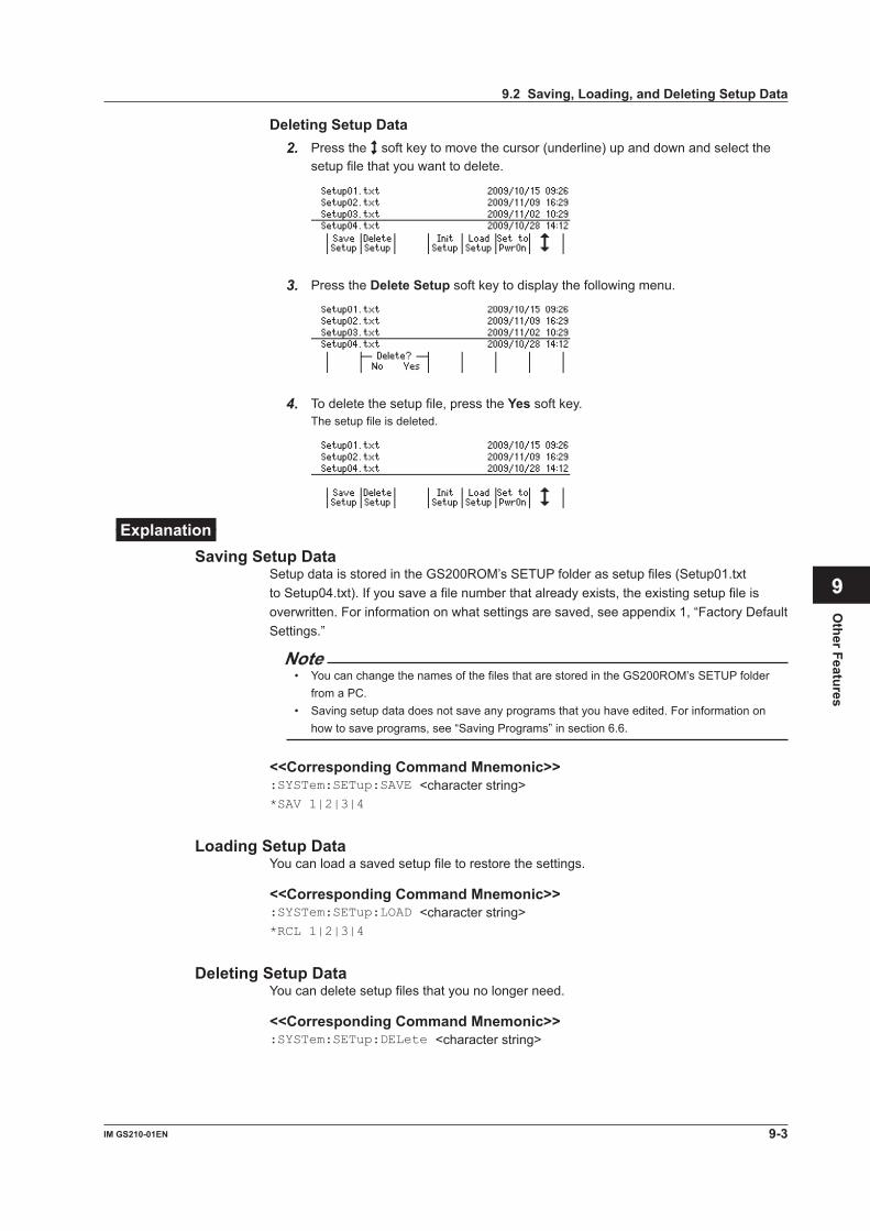
Deleting Setup Data2. Press the soft key to move the cursor (underline) up and down and select the
setup file that you want to delete.
3. Press the Delete Setup soft key to display the following menu.
4. To delete the setup file, press the Yes soft key.The setup file is deleted.
ExplanationSaving Setup Data
Setup data is stored in the GS200ROM’s SETUP folder as setup files (Setup01.txt to Setup04.txt). If you save a file number that already exists, the existing setup file is overwritten. For information on what settings are saved, see appendix 1, “Factory Default Settings.”
Note• You can change the names of the files that are stored in the GS200ROM’s SETUP folder
from a PC.• Saving setup data does not save any programs that you have edited. For information on
how to save programs, see “Saving Programs” in section 6.6.
<<Corresponding Command Mnemonic>>:SYSTem:SETup:SAVE <character string>*SAV 1|2|3|4
Loading Setup DataYou can load a saved setup file to restore the settings.
<<Corresponding Command Mnemonic>>:SYSTem:SETup:LOAD <character string>*RCL 1|2|3|4
Deleting Setup DataYou can delete setup files that you no longer need.
<<Corresponding Command Mnemonic>>:SYSTem:SETup:DELete <character string>
9.2 Saving, Loading, and Deleting Setup Data
9-3IM GS210-01EN
Other Features
3
2
1
4
5
6
7
8
9
10
11
12
13
14
15
App
Index

9.3 Selecting the Settings Applied at Power-On
ProcedureSelecting the Settings Applied at Power-On
1. Press SETUP to display the following menu.
2. Press the soft key to move the cursor (underline) up and down and select the setup file that you want to load the settings from when the GS200 turns on.
3. Press the Set to PwrOn soft key.An asterisk is displayed to the left of the setup file that you selected.
Clearing the Settings Applied at Power-On2. Press the soft key to move the cursor (underline) up and down and select the
setup file that has an asterisk displayed to the left of its file name.
3. Press the Clear PwrOn soft key.The asterisk disappears.
ExplanationIf you select the settings applied at power-on, the selected setup file is loaded automatically when the GS200 turns on. If you clear the settings applied at power-on, the factory default settings are loaded each time that the GS200 turns on. For information on the factory default settings, see appendix 1, “Factory Default Settings.”
<<Corresponding Command Mnemonic>>:SYSTem:SETup:PON <character string>
9-4 IM GS210-01EN
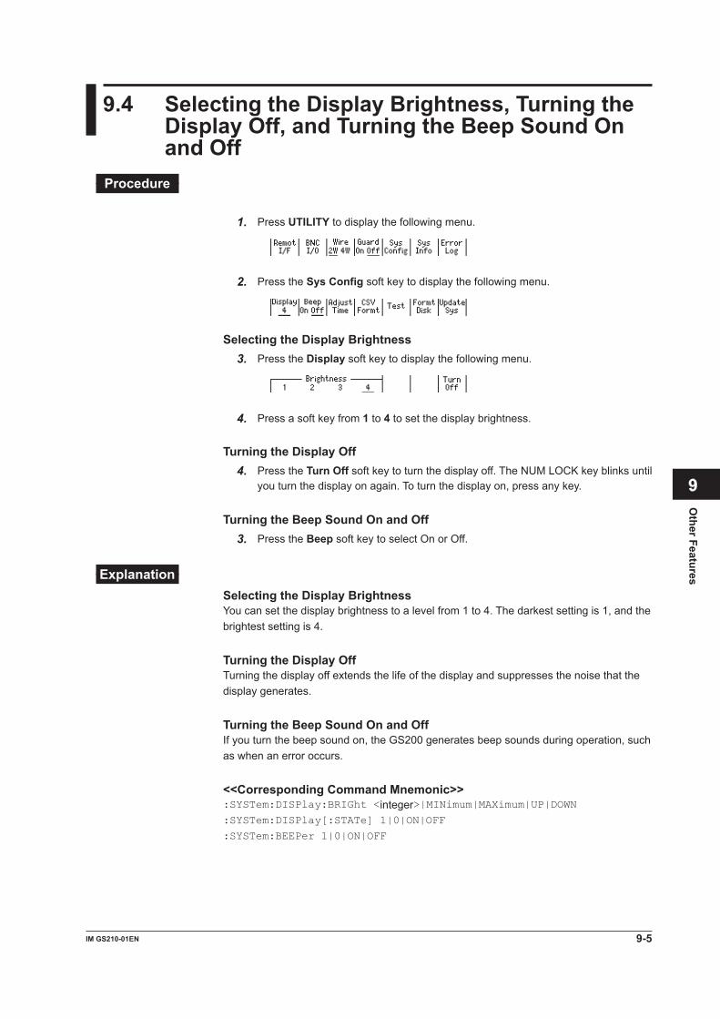
9.4 Selecting the Display Brightness, Turning the Display Off, and Turning the Beep Sound On and Off
Procedure
1. Press UTILITY to display the following menu.
2. Press the Sys Config soft key to display the following menu.
Selecting the Display Brightness3. Press the Display soft key to display the following menu.
4. Press a soft key from 1 to 4 to set the display brightness.
Turning the Display Off4. Press the Turn Off soft key to turn the display off. The NUM LOCK key blinks until
you turn the display on again. To turn the display on, press any key.
Turning the Beep Sound On and Off3. Press the Beep soft key to select On or Off.
ExplanationSelecting the Display BrightnessYou can set the display brightness to a level from 1 to 4. The darkest setting is 1, and the brightest setting is 4.
Turning the Display OffTurning the display off extends the life of the display and suppresses the noise that the display generates.
Turning the Beep Sound On and OffIf you turn the beep sound on, the GS200 generates beep sounds during operation, such as when an error occurs.
<<Corresponding Command Mnemonic>>:SYSTem:DISPlay:BRIGht <integer>|MINimum|MAXimum|UP|DOWN:SYSTem:DISPlay[:STATe] 1|0|ON|OFF
:SYSTem:BEEPer 1|0|ON|OFF
9-5IM GS210-01EN
Other Features
3
2
1
4
5
6
7
8
9
10
11
12
13
14
15
App
Index

9.5 Selecting the CSV File Format
Procedure1. Press UTILITY to display the following menu.
2. Press the Sys Config soft key to display the following menu.
3. Press the CSV Formt soft key to display the following menu.
4. Press the Point or Sep soft key to select the CSV file format.The two soft keys are linked.
ExplanationThe following format combinations are available.• The decimal point is a period, and the separator is a comma.• The decimal point is a comma, and the separator is a semicolon.The default setting is the period and comma combination.
9-6 IM GS210-01EN

9.6 Error Log Display
ProcedureError Log Display
1. Press UTILITY to display the following menu.
2. Press the Error Log soft key to display the error log.
Error description
Displayed when the error log contains six lines or more.
3. If the error log contains six lines or more, press the soft key to scroll the display.
Clearing the Error Log Display4. Press the Clear soft key to clear the error log.
ExplanationThe ERROR indicator illuminates if an error such as a runtime error or communication command error is stored in the error memory.The error log displays errors and messages. An error has an associated error number, and a message does not.A message is displayed in the error log until the problem indicated by the message is resolved. It is not cleared even if the Clear soft key is pressed.For the meaning of errors and their corrective actions, see section 14.2, “Error Code Descriptions and Corrective Actions.”
Note• The error memory is also cleared if you use a communication command
(“:SYSTem:ERRor?”) to read errors, or if the GS200 is turned off. You can also clear the error memory by sending the *CLS communication command.
• If the error memory becomes full, “–350: Queue overflow” is entered as the last error indicating that any additional errors will be discarded. When the error memory is cleared, the ERROR indicator turns off.
<<Corresponding Command Mnemonic>>:SYSTem:ERRor?
:STATus:ERRor?
*CLS
9-7IM GS210-01EN
Other Features
3
2
1
4
5
6
7
8
9
10
11
12
13
14
15
App
Index

10-1IM GS210-01EN
USB
Interface
10.1 USB Interface Features and Specifications
USB Interface FeaturesUSB Storage FeatureYou can access the two disks, GS200ROM and GS200RAM as external removable disks on your PC (see section 4.4, “USB Storage Feature”).
USB-TMC Command Control FeatureYou can control the GS200 by using commands from a VISA (Virtual Instrument Software Architecture) library.To perform USB-TMC command control, you must first install a VISA library on your PC.
USB Interface SpecificationsElectrical and mechanical specifications: Conforms to USB 2.0Connector: Type B connector (receptacle)Number of ports: 1Power supply: Self-powered
Connecting to a NetworkConnection CableUse a USB cable that has a type B connector (receptacle). For the connection procedure, see section 4.4, “USB Storage Feature.”
Chapter 10 USB Interface
3
2
1
4
5
6
7
8
9
10
11
12
13
14
15
App
Index

10-2 IM GS210-01EN
10.2 Setting the USB Interface Mode
Procedure1. Press UTILITY to display the following menu.
2. Press the Remot I/F soft key to display the following menu.
Setting the USB Interface Mode3. Press the USB soft key to display the following menu.
4. Press the soft key that corresponds to the USB interface mode that you want to use.
ExplanationSetting the USB Interface ModeStorag (Storage)Select Storag to use the USB storage feature (see section 4.4, “USB Storage Feature”).
TMC (USB-TMC)Select TMC to perform command control from a VISA library.

10-3IM GS210-01EN
USB
Interface
10.3 Viewing the VISA Setup Information
Procedure1. Press UTILITY to display the following menu.
2. Press the Remot I/F soft key to display the following menu.
Viewing the VISA Information3. Press the VISA Info soft key to display the network setup information that is
necessary for communications using a VISA library.
ExplanationThe VISA information contains a character string that is passed to viOpen() to open a device using a VISA library.GPIB: The character string that is passed to viOpen() when using the GP-IB
interface.USB: The character string that is passed to viOpen() when using the USB-TMC
protocol.LAN: The character string that is passed to viOpen() when using the Ethernet VXI-
11 protocol.
3
2
1
4
5
6
7
8
9
10
11
12
13
14
15
App
Index

11-1IM GS210-01EN
Ethernet Interface (Option)
11.1 Ethernet Interface Features and Specifications
Ethernet Interface FeaturesVXI-11 Server FeatureThe VXI-11 server feature is a command mnemonic stream parsing server based on the VXI-11 protocol that allows up to five clients to connect to it on port 111.
Command Control Server FeatureThe command control server feature is a command mnemonic stream parsing server that allows up to five clients to connect to it on port 7655.The terminator (CR, LF, or CR+LF) can be specified.
FTP Server FeatureThe FTP server feature is an anonymous FTP server that allows up to five clients to connect to it on port 21.
HTTP Server Feature The HTTP server feature (connected to on port 80) enables you to use a Web browser to display various GS200 information and control the GS200 remotely.
Ethernet Interface SpecificationsConnector: RJ-45Number of ports: 1Electrical and mechanical specifications: Conforms to IEEE 802.3Transmission system: 100BASE-TX/10BASE-TMaximum data rate: 100 MbpsProtocol: TCP/IP
Chapter 11 Ethernet Interface (Option)
3
2
1
4
5
6
7
8
9
10
11
12
13
14
15
App
Index
11-2 IM GS210-01EN
11.2 Connecting to a Network
Connect a UTP (Unshielded Twisted-Pair) cable or an STP (Shielded Twisted-Pair) cable that is connected to a hub or other network device to the 100BASE-TX port on the GS200 rear panel.
RJ-45 modular jack
ETHERNET port
LINK indicator Illuminates when a link is established between the GS200 and another device and the devices are capable of communicating with each other
ACT indicator Blinks when packet transmission is in progress
LINK
ETHERNET
ACT
100BASE-TX
Connection CableUse one of the following cables to connect the GS200 to a network.• A UTP (unshielded twisted pair) cable (category 5 or better)• An STP (shielded twisted pair) cable (category 5 or better)
To Connect to a PC over a Network
GS200
Hub or router that supports 100BASE-TX
UTP or STP cable (straight cable)
Network card
PC
To Connect to a PC through a Hub or Router
GS200
Hub or router that supports 100BASE-TX
UTP or STP cable (straight cable)
Network card
PC
Note• Use straight UTP or STP cables that are category 5 or better.• Do not connect the GS200 to a PC directly. Direct communication without a hub or router is
not guaranteed to work.

11-3IM GS210-01EN
Ethernet Interface (Option)
11.3 Configuring Network Settings (TCP/IP)
Procedure1. Press UTILITY to display the following menu.
2. Press the Remot I/F soft key to display the following menu.
3. Press the LAN soft key to display the following menu.
Turning DHCP On and Off4. Press the DHCP soft key to select On or Off.
Setting the IP AddressYou can only set the IP address when DHCP is off.
5. Press the IP Adrs soft key to display the IP address setup screen.The NUM LOCK key illuminates, and the GS200 changes to keypad mode.
6. Press the and keys that correspond to numbers 0 to 9 and the period to set the IP address.
7. Press the Enter soft key to confirm the setting.
Setting the Subnet MaskYou can only set the subnet mask when DHCP is off.
5. Press the Subnet Mask soft key to display the subnet mask setup screen.The NUM LOCK key illuminates, and the GS200 changes to keypad mode.
6. Press the and keys that correspond to numbers 0 to 9 and the period to set the subnet mask.
3
2
1
4
5
6
7
8
9
10
11
12
13
14
15
App
Index

11-4 IM GS210-01EN
7. Press the Enter soft key to confirm the setting.
Setting the Default GatewayYou can only set the default gateway when DHCP is off.
5. Press the Defalt Gatwy soft key to display the default gateway setup screen.The NUM LOCK key illuminates, and the GS200 changes to keypad mode.
6. Press the and keys that correspond to numbers 0 to 9 and the period to set the default gateway.
7. Press the Enter soft key to confirm the setting.
Setting the Transmission Terminator5. Press the Term soft key to display the following menu.
6. Press the soft key that corresponds to the terminator that you want to use.
Restarting the GS200You must restart the GS200 to apply any new or changed network settings other than the transmission terminator setting.
ExplanationTo use the GS200’s network features, you must configure the TCP/IP settings.
DHCP (Dynamic Host Configuration Protocol)DHCP is a protocol that temporarily allocates necessary information to a computer so that it can connect to the Internet. If DHCP is turned on, the following settings will be automatically assigned.• IP address• Subnet mask• Default gateway
• To use DHCP, the network must have a DHCP server. Consult your network administrator to see if DHCP is available.
• Different information may be assigned to the GS200 each time it is turned on. When you are using a PC to access the GS200, you must check the GS200 IP address and other network settings each time you turn the GS200 on.
11.3 Configuring Network Settings (TCP/IP)

11-5IM GS210-01EN
Ethernet Interface (Option)
IP Address (Internet Protocol Address)• An IP address is a 32-bit value that is expressed using four octets. Each octet is
separated by a period and has a value from 0 to 255, as in “192.168.111.24.”• Obtain an IP address from your network administrator.• The IP address is automatically assigned in networks that use DHCP.
Subnet Mask• Consult your network administrator for the subnet mask address. You may not need to
set the subnet mask.• The subnet mask address is automatically assigned in networks that use DHCP.
Default GatewayThe default gateway setting is necessary to communicate between different subnets.• Consult your network administrator for the default gateway address. You may not
need to set the default gateway.• The default gateway address is automatically assigned in networks that use DHCP.
Transmission TerminatorYou can set the terminator that is used to send data from the command control server at port 7655.• Select CR, LF, or CR+LF.• The GS200 handles CR, LF, or CR+LF as the terminator when receiving data.
Note• You must restart the GS200 to apply any changed network settings other than the
transmission terminator setting.• You must also specify network settings, such as the IP address, on your PC. For information
on these settings, check your PC’s manual (help file) or consult your network administrator.
Viewing the VISA InformationThe VISA information contains a character string that is passed to viOpen() to open a device using a VISA library.For information on how to view the VISA information, see section 10.3.
11.3 Configuring Network Settings (TCP/IP)
3
2
1
4
5
6
7
8
9
10
11
12
13
14
15
App
Index
11-6 IM GS210-01EN
11.4 Viewing the Network Settings
Procedure1. Press UTILITY to display the following menu.
2. Press the Remot I/F soft key to display the following menu.
3. Press the LAN soft key to display the LAN menu.
Viewing the Network Settings4. Press the Over-view soft key to display the currently active network settings. Any
changes that you have made to these settings are not displayed until you restart the GS200.
ExplanationYou can view the following network settings.• MAC address The MAC address is a unique 48-bit address assigned to the GS200.• IP address (see section 11.3)• Subnet mask (see section 11.3)• Default gateway (see section 11.3)
NoteIf DHCP is enabled, “0.0.0.0” will be displayed for the IP address, subnet mask, and default gateway until an address is assigned to the GS200. If the display does not change even after 30 seconds elapses after the GS200 is turned on, the DHCP address assignment may have failed. If this happens, check that the Ethernet cable is connected correctly and that the LINK indicator of the 100BASE-TX port on the rear panel is illuminated, and then restart the GS200.

11-7IM GS210-01EN
Ethernet Interface (Option)
11.5 Web Server Feature
The GS200 Web server feature links the Web browser on your PC to the GS200 and enables you to control the GS200 from your Web browser window. The GS200 Web server provides you with the following features.• Remote panel feature You can use the keys on the remote panel to set or operate the GS200.• Command control feature You can send communication commands from the command control screen to set or
query the GS200.• Communication environment display You can view the communication settings on the status display.• FTP server feature You can view the files on the GS200’s volatile disk (GS200RAM) and non-volatile disk
(GS200ROM) and transmit or copy files to your PC.
Environment on the GS200Use the Ethernet interface to connect the GS200 to a network. For the connection procedure, see section 11.2. For details on network settings, see section 11.3.
3
2
1
4
5
6
7
8
9
10
11
12
13
14
15
App
Index
11-8 IM GS210-01EN
Preparations on Your PCLogging into the Web Server (GS200)
1. Start Internet Explorer.
2. Type the IP address of the GS200 in the Address box, and press ENTER. IP address example: http://10.0.159.30/
3. If a connection to the GS200 Web server is established, the top page of the GS200 Web Service is displayed.
Web Server Window
FTP server featureCommunication environment display
Command control featureRemote panel feature
Link to the YOKOGAWA website’s top page
Link to the YOKOGAWA website’s GS200 page
11.5 Web Server Feature

11-9IM GS210-01EN
Ethernet Interface (Option)
Using the Web Server FeatureRemote Panel FeatureClick the “Remote Panel” link in the Web server window to display an image of the GS200 front panel.
Click to update the remote panel to reflect the operations carried out on the GS200
Click to automatically update the remote panel to reflect the operations carried out on the GS200
Set the update interval
You can control the GS200 in the same manner as if you were using the actual keys on the GS200. Use your mouse to click the keys that you want to operate. Operations that you perform on the remote panel are immediately applied to the GS200. To update the remote panel so that it accurately reflects the current operations of the GS200, click Update Panel. Click Start Auto Update to automatically apply the operations on the GS200 to the remote panel at the interval specified in the Interval box.
11.5 Web Server Feature
3
2
1
4
5
6
7
8
9
10
11
12
13
14
15
App
Index

11-10 IM GS210-01EN
Command Control FeatureClick the “Command Control” link in the Web server window to display the command control page.
Command transmission area
Response display area
Send the command
You can send communication commands from the command control page to set or query the GS200. Type the communication command in the command transmission area, and click submit. The response to the transmitted communication command is displayed in the response display area.
Displaying the Communication EnvironmentClick the “Status” link in the Web server window to display the communication environment page.
The communication environment of the GS200 is displayed. Click Refresh to update the displayed information.
11.5 Web Server Feature
11-11IM GS210-01EN
Ethernet Interface (Option)
FTP Server FeatureClick the “FTP” link in the Web server window to display the FTP page.
The GS200 volatile disk (GS200RAM) and non-volatile disk (GS200ROM) are displayed. You can view, duplicate, delete, or transfer these files to your PC from the FTP page. For details on the volatile disk (GS200RAM) and non-volatile disk (GS200ROM), see “USB Storage Feature” on page 2-25.
11.5 Web Server Feature
3
2
1
4
5
6
7
8
9
10
11
12
13
14
15
App
Index

12-1IM GS210-01EN
GP-IB
Interface
12.1 GP-IB Interface Features and Specifications
GP-IB Interface FeaturesListener Capability• You can use the GP-IB interface to specify the same settings that you can using
the front panel keys. You cannot use it to turn the GS200 on and off or change communication settings.
• The GP-IB interface receives output requests for setup data and measured data from the controller.
• The interface can also receive commands such as status report commands.
Talker CapabilityThe GP-IB interface transmits setup data, waveform data, and other types of data.
NoteTalk-only, listen-only, and controller capabilities are not available on the GS200.
Switching between Remote and Local ModesWhen Switching from Local to Remote ModeThe GS200 switches to remote mode when it is in local mode and it receives a REN (Remote Enable) message from the controller.• The REMOTE indicator illuminates (see section 1.1).• All keys other than the LOCAL key are locked.• Settings entered in local mode are retained even when the GS200 switches to remote
mode.
When Switching from Remote to Local ModeThe GS200 switches to local mode when it is in remote mode and you press the LOCAL key.• The REMOTE indicator turns off.• Key operations are enabled.• Settings entered in remote mode are retained even when the GS200 switches to local
mode.
GP-IB Interface Specifications• Electrical and mechanical specifications: Conforms to IEEE St’d 488-1987• Mechanical specifications: See the table below.• Used codes: ISO (ASCII) codes• Mode: Addressable mode• Address selection: On the GP-IB Address menu, set the GP-IB address
setting (see section 12.3) to an address from 0 to 30.• Clearing remote mode: Clear remote mode by pressing LOCAL. However, key
operations are invalid when Local Lockout is enabled by the controller.
Feature Subset Name DescriptionSource handshaking SH1 Full source handshaking capability.Acceptor handshaking AH1 Full acceptor handshaking capability.Talker T6 Basic talker capability, serial polling, and untalk on
MLA (My Listen Address). No talk-only capability.Listener L4 Basic listener capability and unlisten on MTA (My
Talk Address). No listen-only capability.Service request SR1 Full service request capability.Remote local RL1 Full remote/local capability.Parallel polling PP0 No parallel polling capability.Device clear DC1 Full device clear capability.Device trigger DT1 Device trigger capability.Controller C0 No controller capability.Electric characteristics E1 Open collector.
Chapter 12 GP-IB Interface
3
2
1
4
5
6
7
8
9
10
11
12
13
14
15
App
Index

12-2 IM GS210-01EN
12.2 Connecting the GP-IB Cable
GP-IB CableThe GS200 is equipped with an IEEE St’d 488-1987 24-pin GP-IB connector. Use a GP-IB cable that conforms to this standard.
Connection ProcedureConnect the cable as shown below.
GP-IB connector
GP-IB cable
Precautions to Be Taken When Connecting the Cable• Firmly tighten the screws on the GP-IB cable connector.• Multiple devices can be connected in a single GP-IB system. However, the maximum
number of devices that can be connected in any such system (including the controller) is 15.
• When connecting multiple devices, you must assign a unique address to each device.• Use cables that are 2 m or shorter in length to connect devices.• Make sure the total length of all cables does not exceed 20 m.• When devices are communicating, have at least two-thirds of the devices on the bus
turned on.• To connect multiple devices, wire them in a daisy-chain or star configuration as shown
below. You can also mix these configurations. Loop configuration is not allowed.

12-3IM GS210-01EN
GP-IB
Interface
12.3 Setting the GP-IB Address and Command Mode
Procedure1. Press UTILITY to display the following menu.
2. Press the Remot I/F soft key to display the following menu.
3. Press the GPIB soft key to display the following menu.
Setting the GP-IB Address4. Press the Adrs soft key.
5. In up/down key mode, press the and keys to set the GP-IB address. In keypad mode, press NUM LOCK + or to set the GP-IB address.
Setting the GP-IB Command Mode4. Press the GS200 or 7651 soft key to set the GP-IB command mode.
ExplanationGP-IB AddressEach device that is connected by GP-IB has its own unique address in the GP-IB system. This address is used to distinguish between different devices. When you connect the GS200 to a controller such as a PC, specify the GS200’s GP-IB address on the controller.Range: 0 to 30
GP-IB Command ModeGS200 ModeGS200 mode enables you to use protocol commands that conform to IEEE St’d 488.2-1992. For details on commands, see chapter 13.
7651 Mode7651 mode enables you to use the same commands that are available for the YOKOGAWA 7651 Programmable DC Source. For details on these commands, see section 12.4.
Viewing the VISA InformationThe VISA information contains a character string that is passed to viOpen() to open a device using a VISA library.For information on how to view the VISA information, see section 10.3.
3
2
1
4
5
6
7
8
9
10
11
12
13
14
15
App
Index

12-4 IM GS210-01EN
12.4 7651-Compatible Mode
You can use the same communication commands with the GS200 that are available for the YOKOGAWA 7651 Programmable DC Source. This is useful when you replace the 7651 with the GS200 or if you want to use both the GS200 and the 7651 in the same system and control them using the same commands.
NoteYou can only use the 7651-compatible mode with GP-IB communication. You cannot use it with communication through other communication interfaces.
Setting the GP-IB Command ModeFollow the procedure in section 12.3 to set the GP-IB command mode to 7651 mode.
Communication Commands That You Can Use in 7651 ModeSee the 7651 User’s Manual, IM7651-01E.However, there are the following limitations.• The following commands are not supported.
• IC memory card initialization (CI)• Calibration feature commands (YZPm, YZSm, YZW, YZE, and YZO)• RS-232-C-specific commands (<ESC>R, <ESC>L, <ESC>S, and <ESC>C)
• In the return value of the status output command (OC):• The CAL switch bit and the normal/calibration mode bit are always 0.• The IC memory card bit is always 1.
• If parameters are not included for communication commands that require parameters, a communication error occurs.
• The semicolon terminator is not supported.
The 7651-Mode Status ByteIn 7651 mode, the status byte is also 7651-compatible. For details, see the 7651 User’s Manual, IM7651-01E.
Using Keys to Issue SRQ InterruptionsIf you press the ENTER key when the GP-IB command mode is set to 7651, the status byte’s SRQ SW bit is set to 1. The GS200 issues an SRQ interruption if it is set to use the SRQ SW bit as an interruption source. For details, see the 7651 User’s Manual, IM7651-01E.

12-5IM GS210-01EN
GP-IB
Interface
12.5 Responses to Interface Messages
What Are Interface Messages?Interface messages are also referred to as interface commands or bus commands. They are commands that are issued by the controller. They are classified as follows:
Uni-line MessagesA single control line is used to transmit uni-line messages. The following three types of messages are available.IFC (Interface Clear), REN (Remote Enable), and IDY (Identify)
Multi-line MessagesEight data lines are used to transmit multi-line messages. The messages are classified as follows:• Address Commands These commands are valid when the instrument is designated as a listener or as a
talker. The following five commands are available.• Commands that are valid on an instrument that is designated as a listener GTL (Go To Local), SDC (Selected Device Clear), PPC (Parallel Poll Configure),
and GET (Group Execute Trigger)• A command that is valid on an instrument that is designated as a talker TCT (Take Control)
• Universal Commands These commands are valid on all instruments regardless of their listener or talker
designation. The following five commands are available. LLO (Local Lockout), DCL (Device Clear), PPU (Parallel Poll Unconfigure), SPE (Serial
Poll Enable), and SPD (Serial Poll Disable)
Other Interface MessagesListener address, talker address, and secondary commands are also considered interface messages.
Difference between SDC and DCLIn multi-line messages, SDC messages are those that require talker or listener designation and DCL messages are those that do not require a designation. Therefore, SDC messages are directed at a particular instrument while DCL messages are directed at all instruments on the bus.
3
2
1
4
5
6
7
8
9
10
11
12
13
14
15
App
Index
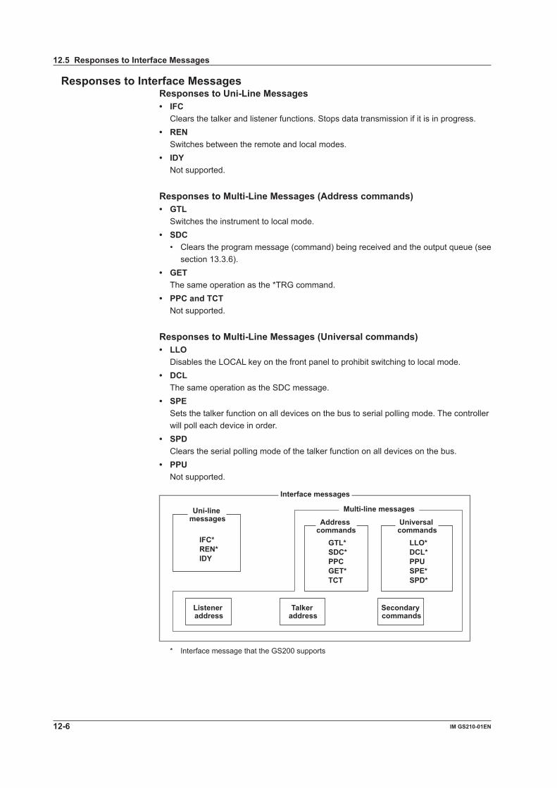
12-6 IM GS210-01EN
Responses to Interface MessagesResponses to Uni-Line Messages• IFC Clears the talker and listener functions. Stops data transmission if it is in progress.• REN Switches between the remote and local modes.• IDY Not supported.
Responses to Multi-Line Messages (Address commands)• GTL Switches the instrument to local mode.• SDC
• Clears the program message (command) being received and the output queue (see section 13.3.6).
• GET The same operation as the *TRG command.• PPC and TCT Not supported.
Responses to Multi-Line Messages (Universal commands)• LLO Disables the LOCAL key on the front panel to prohibit switching to local mode.• DCL The same operation as the SDC message.• SPE Sets the talker function on all devices on the bus to serial polling mode. The controller
will poll each device in order.• SPD Clears the serial polling mode of the talker function on all devices on the bus.• PPU Not supported.
Interface messages
Uni-line messages Address
commandsUniversal commands
IFC*REN*IDY
GTL*SDC*PPCGET*TCT
LLO*DCL*PPUSPE*SPD*
Listener address
Talker address
Secondary commands
Multi-line messages
* Interface message that the GS200 supports
12.5 Responses to Interface Messages

12-7IM GS210-01EN
GP-IB
Interface
12.6 About the IEEE 488.2-1992 Standard
The GS200’s GP-IB interface conforms to the IEEE 488.2-1992 standard. This standard specifies that the following 23 items be stated in the document. This section describes these items.
(1) Of the IEEE 488.1 interface functions, the subsets that are supported See “GP-IB Interface Specifications” on page 12-1.
(2) The operation of the device when it is assigned an address outside the 0 to 30 range.
The address of this instrument cannot be set to an address outside the 0 to 30 range.
(3) Reaction of the device when the user changes the address The address change is detected when the address is set on the GP-IB Address
menu (see section 12.3). The new address is valid until the next time it is changed.
(4) Device settings at power-up. The commands that can be used at power-up. The settings selected in section 9.3, “Selecting the Settings Applied at Power-On.”
If you issue the RST common command, the GS200 always returns to the factory default settings.
(5) Message exchange options (a) Input buffer size 64 KB. (b) Queries that return multiple response messages See the example of the commands given in section 13.2. (c) Queries that create response data when the command syntax is being analyzed All queries create response data when the command syntax is analyzed. (d) Queries that create response data during reception There are no queries of which the response data are created upon receiving a
send request from the controller. (e) Commands that have parameters that restrict one another See the example of the commands given in section 13.2.
(6) Items that are included in the functional or composite header elements constituting a command
See sections 13.1 and 13.2.
(7) Buffer sizes that affect block data transmission The buffer size of block data is 2 MB.
(8) A list of program data elements that can be used in equations and their nesting limitations
Equations cannot be used.
(9) Syntax of the responses to queries See the example of the commands given in section 13.2.
(10) Communication between devices that do not follow the response syntax Not supported.
3
2
1
4
5
6
7
8
9
10
11
12
13
14
15
App
Index
12-8 IM GS210-01EN
(11) Size of the response data block 2 MB maximum.
(12) A list of supported common commands See section 13.2.11, “Common Commands.”
(13) Device condition after a successful calibration The settings return to the conditions that existed before the calibration,
measurements are terminated, and previous measured data are invalidated.
(14) The maximum length of block data that can be used for the *DDT trigger macro definition
Not supported.
(15) The maximum length of the macro label for defining macros, the maximum length of block data that can be used for the macro definition, and the process when recursion is used in macro definitions
Macro functions are not supported.
(16) Reply to the *IDN? query See section 13.2.11, “Common Commands.”
(17) Size of storage area for protected user data for PUD and *PUD? *PUD and *PUD? are not supported.
(18) The length of the *RDT and *RDT? resource names *RDT and *RDT? are not supported.
(19) The change in the status due to *RST, *LRN?, *RCL, and *SAV *RST, *RCL, and *SAV See section 13.2.11, “Common Commands.” *LRN? This common command is not supported.
(20) The extent of the self-test using the *TST? command Performs a test that is equivalent to the self-test that is executed from the front
panel. Returns 0 if successful, otherwise returns an error code. The self-test consists of the RAM test, ROM test, and digital test.
(21) The structure of the extended return status See section 13.3.
(22) Whether each command is processed in an overlapped manner or sequentially All commands are sequential commands.
(23) The description of the execution of each command See the functional and procedural explanations given in chapters 1 to 12 and 14.
12.6 About the IEEE 488.2-1992 Standard

13.1 Program Format
13.1.1 Symbols Used in the SyntaxThe following table contains the symbols that are used in the syntax discussed mainly in section 13.2. For details on the data, see pages 13-5 and 13-6.
Symbol Meaning Example| Exclusive OR SOURce:FUNCtion VOLTage|CURRent
Example SOURce:FUNCTION VOLTage[] Can be omitted OUTPut[:STATe]
... Can be repeated
13.1.2 Messages
MessagesMessages are used to exchange information between the controller and the GS200. Messages that are sent from the controller to the GS200 are called program messages, and messages that are sent from the GS200 back to the controller are called response messages.If a program message contains a message unit that requests a response (a query), the GS200 returns a response message upon receiving the program message. The GS200 returns a single response message in response to a single program message.
Program MessagesData that is sent from the controller to the GS200 is called a program message. The program message format is shown below.
<PMT>
;
<Program message unit>
<Program Message Unit>A program message consists of one or more program message units; each unit corresponds to one command. The GS200 executes the commands in the order that they are received.Separate each program message unit with a semicolon.For details on the syntax of program message units, see the next section.
Example
Unit Unit
:SOURce:FUNCtion VOLTage;RANGe 100E-3<PMT>
Chapter 13 Communication Commands
13-1IM GS210-01EN
Com
munication C
omm
ands
3
2
1
4
5
6
7
8
9
10
11
12
13
14
15
App
Index

<PMT><PMT> is a program message terminator. The following three types of program terminators are available.• NL (New line) Same as LF (line feed). ASCII code “0AH.”• ^END The END message (EOI signal) as defined in
IEEE488.1. (The data byte that is sent with the END message is the last data of the program message.)
• NL^END NL with an END message attached. (NL is not
included in the program message.)
Program Message Unit SyntaxThe program message unit syntax is shown below.
,
<Program header> <Program data>Space
<Program Header>The program header indicates the command type. For details, see page 13-3.
<Program Data>Attach program data if there are conditions that are required to execute a command. Separate the program data from the header with a space (ASCII code 20H). If there are multiple sets of program data, separate each set with a comma.For details, see page 13-5.
Example
Header Data
:SOURce:FUNCtion VOLTage<PMT>
Response MessagesData that is sent from the GS200 to the controller is called a response message. The response message syntax is shown below.
<RMT>
;
<Response message unit>
<Response Message Unit>A response message consists of one or more response message units; each response message unit corresponds to one response.Separate each response message unit with a semicolon.For details on the syntax of response message units, see the next section.
Example
Unit Unit
:SOURce:FUNCtion VOLTage;RANGe 100E-3<RMT>
<RMT>RMT is a response message terminator. It is NL^END.
Response Message Unit SyntaxThe response message unit syntax is shown below.
,
<Response data>
<Response Header>A response header sometimes precedes the response data. Separate the data from the header with a space. For details, see page 13-5.
<Response Data>Response data contains the content of the response. If there are multiple sets of response data, separate each set with a comma.
Example50.0E-3<RMT>1,256<RMT>VOLT<RMT>
If there are multiple queries in a program message, responses are returned in the same order that the queries were received in. In most cases, a single query returns a single response message unit, but there are a few queries that return multiple units. The first response message unit always corresponds to the first query, but the nth response unit may not necessarily correspond to the nth query. Therefore, if you want to make sure that every response is retrieved, divide the program messages into individual messages.
13.1 Program Format
13-2 IM GS210-01EN

Precautions to Be Taken when Sending and Receiving Messages• If the controller sends a program message that does
not contain a query, the controller can send the next program message at any time.
• If the controller sends a program message that contains a query, the controller must finish receiving the response message before it can send the next program message. If the controller sends the next program message before receiving the response message in its entirety, an error will occur. A response message that is not received in its entirety will be discarded.
• If the controller tries to receive a response message when there is none, an error will occur. If the controller tries to receive a response message before the transmission of the program message is complete, an error will occur.
• If the controller sends a message that contains multiple message units, and the message contains an incomplete unit, any program units that follow the incomplete one will not be processed.
DeadlockThe GS200 can store at least 64 KB of messages in its transmit and receive buffers (the number of available bytes varies depending on the operating conditions). If both the transmit and receive buffers become full at the same time, the GS200 will no longer be able to operate. This condition is called a deadlock. If this happens, you can resume operation by discarding response messages.Deadlock will not occur if the program message (including the <PMT>) is kept below 64 KB. Program messages that do not contain queries never cause deadlocks.
13.1.3 Commands
CommandsThere are three types of commands (program headers) that a controller may send to the GS200. The commands differ in their program header formats.
Common Command HeaderCommands that are defined in IEEE 488.2-1987 are called common commands. The common command header syntax is shown below. Be sure to include an asterisk (*) at the beginning of a common command.
* <Mnemonic> ?
Example *CLS
Compound HeaderCommands, other than common commands, that are specific to the GS200 are classified and arranged in a hierarchy according to their functions. The compound header syntax is shown below. Be sure to use a colon to specify a lower hierarchical level.
:
<Mnemonic> ?:
Example :SOURce:FUNCtion
Simple HeaderThese commands are functionally independent and are not contained within a hierarchy. The simple header syntax is shown below.
<Mnemonic> ?:
Example :INITiate
Note A <mnemonic> is an alphanumeric character string.
13.1 Program Format
13-3IM GS210-01EN
Com
munication C
omm
ands
3
2
1
4
5
6
7
8
9
10
11
12
13
14
15
App
Index
When Concatenating CommandsCommand GroupsA command group is a group of commands that have common compound headers arranged in a hierarchy. A command group may contain sub-groups.
Example Group of commands related to source:SOURce:FUNCtion
:SOURce:RANGe
:SOURce:LEVel:FIX
:SOURce:LEVel:AUTO
:SOURce:PROTection:VOLTage
:SOURce:PROTection:CURRent
When Concatenating Commands of the Same GroupThe GS200 stores the hierarchical level of the command that is currently being executed and processes the next command on the assumption that it belongs to the same level. Therefore, the common header section can be omitted for commands that belong to the same group.
Example:SOURce:FUNCtion VOLTage;
RANGe 100E-3<PMT>
When Concatenating Commands of Different GroupsIf the subsequent command does not belong to the same group, place a colon in front of its header.
Example:SOURce:FUNCtion VOLTage;:SENSe:
TRIGger READy<PMT>
When Concatenating Simple HeadersIf a simple header follows another command, place a colon in front of the simple header.
Example:SOURce:FUNCtion VOLTage;:INITiate<PMT>
When Concatenating Common CommandsCommon commands that are defined in IEEE 488.2-1992 are independent of hierarchy. A colon is not needed before a common command.
Example:SOURce:FUNCtion VOLTage;*CLS<PMT>
When Separating Commands with <PMT>If you separate two commands with a terminator, two program messages will be sent. Therefore, the common header must be specified for each command even when commands belonging to the same command group are being concatenated.
Example:SOURce:FUNCtion VOLTage<PMT>:SOURce:
FUNCtio RANGe 100E-3<PMT>
Header Interpretation RulesThe GS200 interprets the header that it receives according to the rules below.• Mnemonics are not case sensitive. Example SOURce can also be written as
source or Source.• The lower-case characters of mnemonics can be
omitted. Example SOURce can also be written as
source or sour.• The question mark at the end of a header indicates
that it is a query. You cannot omit the question mark. Example The shortest abbreviation for
OUTPut? is OUTP?.• If the <x> (value) at the end of a mnemonic is
omitted, it is interpreted as a 1. Example If FILT is specified for FILTer<x>, it means FILTer1.• Parts of commands and parameters enclosed in
square brackets ([ ]) can be omitted. Example OUTPut[:STATe] 1
can be written as OUTPut 1.
13.1 Program Format
13-4 IM GS210-01EN
13.1.4 Responses
When the controller sends a message unit that has a question mark in its program header (a query), the GS200 returns a response message to the query.
13.1.5 Data
DataData contains conditions and values that are written after the header. A space separates the data from the header. Data is classified as follows:
Notation Meaning Example<Integer> — 125 –1
<Fixed-point number> — 125.0 –.90
<Floating-point number> — 125.0E+0 –9E–1
<Value> <Integer>, <Fixed-point number>, or <Floating-point number>
<Voltage> A <Value> to which a voltage unit (V) can be attached.
–1.25mV
<Current> A <Value> to which a current unit (A) can be attached.
–75.1E–2A
<Time> A <Value> to which a time unit (S) can be attached.
360S
<Resistance> A <Value> to which a resistance unit (ohm) can be attached.
4.7kohm
<Binary/Octal/Hexadecimal> A binary number following #B, an octal number following #Q, or a hexadecimal number following #H.
#B1101 #Q706 #H9F3C
<Character string> A character string enclosed by double or single quotation marks.
"Hello"
* In a <floating-point number>, the + sign after E can be omitted.
<Block Data><Block data> is any 8-bit data. It is only used in response messages on the GS200. The syntax is as follows: Syntax Example #N<N-digit decimal number><data byte sequence>
#800000010ABCDEFGHIJ• #N Indicates that the data is <block data>. “N” indicates
the number of succeeding data bytes (digits) in ASCII code.
• <N-digit decimal number> Indicates the number of bytes of data (example:
00000010 = 10 bytes).• <Data byte sequence> Expresses the actual data (example: ABCDEFGHIJ).• Data is comprised of 8-bit values (0 to 255). This
means that the ASCII code “0AH,” which stands for “NL,” can also be included in the data. Hence, care must be taken when programming the controller.
13.1 Program Format
13-5IM GS210-01EN
Com
munication C
omm
ands
3
2
1
4
5
6
7
8
9
10
11
12
13
14
15
App
Index

<Multiplier>The table below lists the <multipliers> that can be added after a <value>.
Symbol Word MultiplierYO Yotta 1024
ZE Zetta 1021
EX Exa 1018
PE Peta 1015
T Tera 1012
G Giga 109
MA Mega 106
K Kilo 103
M Milli 10–3
U Micro 10–6
N Nano 10–9
P Pico 10–12
F Femto 10–15
A Atto 10–18
Z Zepto 10–21
Y Yocto 10–24
13.1 Program Format
13-6 IM GS210-01EN

13.2 Commands
13.2.1 List of CommandsCommand Function Page
Output Commands (OUTPut group):OUTPut
[:STATe]/? Sets or queries the output state (on/off). 13-10
Source Commands (SOURce group):SOURce
:FUNCtion/? Sets or queries the source function (voltage/current). 13-11:RANGe/? Sets or queries the source range. 13-11:LEVel
[:FIX]/? Sets or queries the source level in terms of the range that is being used. 13-11:AUTO/? Sets or queries the source level in terms of the most appropriate range. 13-12
:PROTection:VOLTage/? Sets or queries the voltage limiter level. 13-12:CURRent/? Sets or queries the current limiter level. 13-12
Program Commands (PROGram group):PROGram
:REPeat[:STATe]/? Sets or queries the program execution repetition mode (on/off). 13-13
:INTerval/? Sets or queries the program execution timer’s period. 13-13:SLOPe/? Sets or queries the program slope time. 13-13:TRIGger/? Sets or queries the program trigger. 13-13:EDIT
:STARt Starts program memory editing. 13-13:END Ends program memory editing. 13-13
:SAVE Saves the program memory as a program file. 13-13:LOAD/? Loads a program file into program memory. 13-13:DELete Deletes a program file. 13-14:DEFine Creates a program file. 13-14:MEMory Writes a program file to program memory. 13-14:CATalog? Queries the list of program files. 13-14:RUN Executes a program (RUN execution). 13-14:STEP Executes a program (STEP execution). 13-14:HOLD Pauses and resumes program execution. 13-14:PAUSe Pauses program execution. 13-14:CONTinue Resumes program execution. 13-14:COUNt/? Sets or queries the step that the current program begins execution at. 13-14
Measurement Commands (SENSe group):SENSe
[:STATe]/? Sets or queries the measurement feature (on/off). 13-15:NPLC/? Sets or queries the measurement integration time in terms of PLC. 13-15:DELay/? Sets or queries the measurement delay time. 13-15:TRIGger/? Sets or queries the measurement trigger. 13-15:INTerval/? Sets or queries the measurement timer’s period. 13-16:NULL
[:STATe]/? Sets or queries the NULL computation feature (on/off). 13-16:ZERO
:EXECute Executes measurement zero calibration. 13-16:REMote/? Sets or queries the wiring system (on = 4W/off = 2W). 13-16:GUARd/? Sets or queries the guard state (on/off). 13-16
13-7IM GS210-01EN
Com
munication C
omm
ands
3
2
1
4
5
6
7
8
9
10
11
12
13
14
15
App
Index

Command Function Page
Measured Value Read Commands (INITiate, FETCh, READ, and MEASure groups):INITiate Clears the measured value and prepares the GS200 to perform the next measurement. 13-17:FETCh? Queries the measured result. 13-17:READ? Clears the measured value, prepares the GS200 to perform the next measurement, and queries the measured result. 13-17:MEASure? Clears the measured value, prepares the GS200 to perform the next measurement, generates a measurement trigger, and queries the measured result. 13-17
Store/Recall Commands (TRACe group):TRACe
[:STATe]/? Sets or queries the storage state (on/off). 13-18:FILE
:CREate/? Sets or queries the result file generation feature (on/off). 13-18:POINts/? Sets or queries the storage count. 13-18:ACTual? Queries the number of stored results. 13-18:DATA
:FORMat/? Sets or queries the load format for stored data. 13-18:ENDian/? Sets or queries the byte order for when the load format for stored data is binary. 13-18:READ? [TM|SF|SL|MF|ML] Loads stored data. 13-19:STATistics? Loads statistical values for stored data. 13-19
External I/O Commands (ROUTe group):ROUTe
:BNCO/? Sets or queries the output BNC signal. 13-20:BNCI/? Sets or queries the input BNC signal. 13-20
System Commands (SYSTem group):SYSTem
:SETup
:SAVE Saves setup data. 13-22:LOAD Restores setup data. 13-22:DELete Deletes a setup file. 13-22:CATalog? Queries the list of setup files. 13-22:PON/? Sets or queries the setup data at power-on. 13-22
:DISPlay
[:STATe]/? Sets or queries the display state (on/off). 13-21:BRIGht/? Sets or queries the display brightness. 13-21:TEXT/? Displays or queries the user message. 13-21
:CLEar Clears the user message display. 13-21:NORMal Displays the main screen. 13-21
:BEEPer/? Sets or queries the beep sound (on/off). 13-22:CLOCk
:TZONe/? Sets or queries the time zone. 13-21:DATE/? Sets or queries the date. 13-21:TIME/? Sets or queries the time. 13-21:ADJust Corrects the time by ±30 seconds. 13-22
:ERRor? Queries and clears the most recent error information. 13-22:LOCal Switches the GS200 to local mode. 13-22:REMote Switches the GS200 to remote mode. 13-22:LFRequency? Queries the line frequency. 13-22
13.2 Commands
13-8 IM GS210-01EN

13.2 Commands
13-9IM GS210-01EN
Com
munication C
omm
ands
3
2
1
4
5
6
7
8
9
10
11
12
13
14
15
App
Index
Command Function Page
Status Commands (STATus group):STATus
:CONDition? Queries the condition register. 13-23:EVENt? Queries and clears the extended event register. 13-23:ENABle/? Sets or queries the extended event enable register. 13-23:ERRor? Queries and clears the most recent error information. 13-23
Common Commands*CLS Clears the event register, extended event register, and error queue. 13-24*IDN? Queries the device information. 13-24*OPT? Queries the option information. 13-24*RST Initializes the settings. 13-24*SAV Saves setup data. 13-24*RCL Restores setup data. 13-24*TRG Generates a measurement trigger. 13-24*TST? Performs a self-test and queries the result. 13-24*STB? Queries the status byte. 13-24*SRE/? Sets or queries the service request enable register. 13-24*ESR? Queries and clears the standard event register. 13-24*ESE/? Sets or queries the standard event enable register. 13-24*OPC Generates a standard event OPC when all previous commands complete. 13-25*OPC? Returns 1 when all previous commands complete. 13-25

13.2 Commands
13-10 IM GS210-01EN
:OUTPut[:STATe]/?Function Sets or queries the output state (on/off).Syntax :OUTPut[:STATe] 1|0|ON|OFF
1 or ON Turns the output on. 0 or OFF Turns the output off. :OUTPut[:STATe]?
→ 1 The output is on. → 0 The output is off.Example :OUTP ON
:OUTP:STAT 0
:OUTP?
13.2.2 Output Commands (OUTPut group)
13.2 Commands
13-11IM GS210-01EN
Com
munication C
omm
ands
3
2
1
4
5
6
7
8
9
10
11
12
13
14
15
App
Index
13.2.3 Source Commands (SOURce group)
:SOURce:FUNCtion/?Function Sets or queries the source function (voltage/
current).Syntax :SOURce:FUNCtion VOLTage|CURRent
VOLTage Sets the function to voltage. CURRent Sets the function to current. :SOURce:FUNCtion?
→VOLT Thefunctionbeingusedisvoltage.
→ CURR The function being used is current.
Example :SOUR:FUNC VOLT
:SOUR:FUNC?
Description During program editing, this command sets or queries the current step’s source function.
:SOURce:RANGe/?Function Sets or queries the source range.Syntax :SOURce:RANGe <voltage>|<current>|
MINimum|MAXimum|UP|DOWN
<voltage> Specify a voltage range. The smallest range that
includes the specified voltage is selected.
You have to set the source function to voltage before sending this command.
<current> Specify a current range. The smallest range that
includes the specified current is selected.
You have to set the source function to current before sending this command.
MINimum Sets the range to the minimum range.
MAXimum Sets the range to the maximum range.
UP Increases the range by one level.
DOWN Decreases the range by one level.
:SOURce:RANGe? [MINimum|MAXimum]
MINimum → The minimum range. MAXimum → The maximum range. → 1E-3 The range that is being
used is 1 mA. → 10E-3 The range that is being
used is 10 mV or 10 mA. → 100E-3 The range that is being
used is 100 mV or 100 mA. → 200E-3 The range that is being
used is 200 mA.
→ 1E+0 The range that is being used is 1 V.
→ 10E+0 The range that is being used is 10 V.
→30E+0 Therangethatisbeingused is 30 V.
Example :SOUR:RANG 100E-3
:SOUR:RANG?
Description During program editing, this command sets or queries the current step’s source range.
:SOURce:LEVel[:FIX]/?Function Sets or queries the source level in terms of the
range that is being used.Syntax :SOURce:LEVel[:FIX] <voltage>|<current>|
MINimum|MAXimum
<voltage> Specify a voltage level. You have to set the source
function to voltage before sending this command.
<current> Specify a current level. You have to set the source
function to current before sending this command.
MINimum Sets the level to the minimum value possible with the range that is being used.
MAXimum Sets the level to the maximum value possible with the range that is being used.
:SOURce:LEVel[:FIX]?
[MINimum|MAXimum]
MINimum→ The minimum level possible with the range that is being used.
MAXimum→ Themaximumlevelpossible with the range that is being used.
→<voltage>|<current> Thesourcelevelthatis being produced.
Example :SOUR:LEV 1.5
:SOUR:LEV?
Description During program editing, this command sets or queries the current step’s source level. If you set the current step’s source level, program editing will proceed to the next step.

13.2 Commands
13-12 IM GS210-01EN
:SOURce:LEVel:AUTO/?Function Sets or queries the source level in terms of the
most appropriate range.Syntax :SOURce:LEVel:AUTO <voltage>|<current>|
MINimum|MAXimum
<voltage> Specify a voltage level. The source level is set to
the smallest source range that includes the specified voltage.
You have to set the source function to voltage before sending this command.
<current> Specify a current level. The source level is set to
the smallest source range that includes the specified current.
You have to set the source function to current before sending this command.
MINimum Sets the source range to the maximum range and the source level to the minimum value.
MAXimum Sets the source range to the maximum range and the source level to the maximum value.
:SOURce:LEVel:AUTO?
[MINimum|MAXimum]
MINimum→ The minimum level. MAXimum→ The maximum level. →<voltage>|<current> Thesourcelevelthat
is being produced.Example :SOUR:LEV:AUTO 1.5
:SOUR:LEV:AUTO?
Description During program editing, this command sets or queries the current step’s source level. If you set the current step’s source level, program editing will proceed to the next step.
:SOURce:PROTection:VOLTage/?Function Sets or queries the voltage limiter level.Syntax :SOURce:PROTection:VOLTage <voltage>|
MINimum|MAXimum
<voltage> Specify a voltage limiter level.
MINimum Sets the voltage limiter level to ±1 V.
MAXimum Sets the voltage limiter level to ±30 V.
:SOURce:PROTection:VOLTage?
[MINimum|MAXimum]
MINimum → +1E+0 MAXimum → +30E+0 → <voltage> The voltage limiter level
that is being used.Example :SOUR:PROT:VOLT 14
:SOUR:PROT:VOLT?
:SOURce:PROTection:CURRent/?Function Sets or queries the current limiter level.Syntax :SOURce:PROTection:CURRent <current>|
MINimum|MAXimum
<current> Specify a current limiter level.
MINimum Sets the current limiter level to ±1 mA.
MAXimum Sets the current limiter level to ±200 mA.
:SOURce:PROTection:CURRent?
[MINimum|MAXimum]
MINimum → +1E-3 MAXimum → +200E-3 → <current> The current limiter level
that is being used.Example :SOUR:PROT:CURR 13E-3
:SOUR:PROT:CURR?

13.2 Commands
13-13IM GS210-01EN
Com
munication C
omm
ands
3
2
1
4
5
6
7
8
9
10
11
12
13
14
15
App
Index
13.2.4 Program Commands (PROGram group)
:PROGram:TRIGger/?Function Sets or queries the program trigger.Syntax :PROGram:TRIGger NORMal|MEND
NORMal Sets the trigger normal. MEND Sets the trigger to
measurement end. :PROGram:TRIGger?
→ NORM The normal trigger is being used.
→ MEND The measurement end trigger is being used.
Example :PROG:TRIG MEND
:PROG:TRIG?
Description This command is only valid on models with the /MON option.
:PROGram:EDIT:STARtFunction Starts program memory editing.Syntax :PROGram:EDIT:STARt
Example :PROG:EDIT:STAR
Description Program memory is cleared the moment that you begin editing.
Use the :SOURce:FUNCtion, :SOURce:RANGe, :SOURce:LEVel[:FIX], and :SOURce:LEVel:AUTO commands to configure the program steps.
:PROGram:EDIT:ENDFunction Ends program memory editing.Syntax :PROGram:EDIT:END
Example :PROG:EDIT:END
:PROGram:SAVEFunction Saves the program memory as a program file.Syntax :PROGram:SAVE <character string> <character string> The name of the program
file that you want to save.Example :PROG:SAVE "Test1.csv"
:PROGram:LOAD/?Function Loads a program file into program memory.Syntax :PROGram:LOAD <character string> <character string> The name of the program
file that you want to load. :PROGram:LOAD?
→<characterstring>Thenameoftheprogramfile that has been loaded.
Example :PROG:LOAD "Test1.csv"
:PROG:LOAD?
:PROGram:REPeat[:STATe]/?Function Sets or queries the program execution repetition
mode (on/off).Syntax :PROGram:REPeat[:STATe] 1|0|ON|OFF
1 or ON Turns repetition mode on. 0 or OFF Turns repetition mode off. :PROGram:REPeat[:STATe]?
→ 1 The repetition mode is currently on.
→ 0 The repetition mode is currently off.
Example :PROG:REP ON
:PROG:REP 0
:PROG:REP?
:PROGram:INTerval/?Function Sets or queries the program execution timer’s
period.Syntax :PROGram:INTerval <time>|MINimum|
MAXimum
<time> Specify a timer period. MINimum Sets the timer period to 0.1
seconds. MAXimum Sets the timer period to
3600.0 seconds. :PROGram:INTerval? [MINimum|MAXimum]
MINimum → +0.1E+0 MAXimum → +3600.0E+0 → <time> The timer period that is
being used.Example :PROG:INT 0.5
:PROG:INT?
:PROGram:SLOPe/?Function Sets or queries the program slope time.Syntax :PROGram:SLOPe
<time>|MINimum|MAXimum <time> Specify a slope time. MINimum Sets the slope time to 0.0
seconds. MAXimum Sets the slope time to
3600.0 seconds. :PROGram:SLOPe? [MINimum|MAXimum]
MINimum → +0.0E+0 MAXimum → +3600.0E+0 → <time> The slope time that is being
used.Example :PROG:SLOP 0.5
:PROG:SLOP?

13.2 Commands
13-14 IM GS210-01EN
:PROGram:DELeteFunction Deletes a program file.Syntax :PROGram:DELete <character string> <character string> The name of the program
file that you want to delete.Example :PROG:DEL "Test1.csv"
:PROGram:DEFineFunction Creates a program file.Syntax :PROGram:DEFine
<character string 1>, <character string 2>|<block data> <character string 1> The name of the program
file that you want to create. <character string 2> The contents of the
program file that you want to create.
<block data> The contents of the program file that you want to create.
Example :PROG:DEF "Test1.csv","1.0,1.0,V"
:PROGram:MEMoryFunction Writes a program file to program memory.Syntax :PROGram:MEMory
<character string>|<block data> <character string> The contents of the
program file that you want to write to program memory.
<block data> The contents of the program file that you want to write to program memory.
Example :PROG:MEM "1.0,1.0,V"
:PROGram:CATalog?Function Queries the list of program files.Syntax :PROGram:CATalog?
→ <character string>,... The list of program file names.
Example :PROG:CAT?
:PROGram:RUNFunction Executes a program (RUN execution).Syntax :PROGram:RUN
Example :PROG:RUN
:PROGram:STEPFunction Executes a program (STEP execution).Syntax :PROGram:STEP
Example :PROG:STEP
:PROGram:HOLDFunction Pauses and resumes program execution.Syntax :PROGram:HOLD
Example :PROG:HOLD
Description If a program is running, this command pauses the program execution. If a program is paused, this command resumes the program execution.
:PROGram:PAUSeFunction Pauses program execution.Syntax :PROGram:PAUSe
Example :PROG:PAUS
Description If this command is received while a program is paused, an error will occur.
:PROGram:CONTinueFunction Resumes program execution.Syntax :PROGram:CONTinue
Example :PROG:CONT
Description If this command is received while a program is running, a sampling error will occur.
:PROGram:COUNt/?Function Sets or queries the step that the current program
begins execution at.Syntax :PROGram:COUNt
<integer>|MINimum|MAXimum <integer> Specify a step to begin
execution at. MINimum The step to begin execution
at is set to step 1. MAXimum The step to begin execution
at is set to step 10000. :PROGram:COUNt? [MINimum|MAXimum]
MINimum → 1 MAXimum → 10000 → <integer> The step that is being
executed.Example :PROG:COUN 2
:PROG:COUN?
Description If you specify a step number that is outside of the range designated by 1 and the total number of steps that the specified program contains, an error will occur.
13.2 Commands
13-15IM GS210-01EN
Com
munication C
omm
ands
3
2
1
4
5
6
7
8
9
10
11
12
13
14
15
App
Index
:SENSe[:STATe]/?Function Sets or queries the measurement feature (on/
off).Syntax :SENSe[:STATe] 1|0|ON|OFF
1 or ON Turns the measurement feature on.
0 or OFF Turns the measurement feature off.
:SENSe[:STATe]?
→ 1 The measurement feature is on.
→ 0 The measurement feature is off.
Example :SENS ON
:SENS:STAT 0
:SENS?
Description This command is only valid on models with the /MON option.
:SENSe:NPLC/?Function Sets or queries the measurement integration
time in terms of PLC.Syntax :SENSe:NPLC
<integer>|MINimum|MAXimum <integer> Specify an integration time
in terms of PLC. MINimum Sets the integration time to
1 PLC. MAXimum Sets the integration time to
25 PLC. :SENSe:NPLC? [MINimum|MAXimum]
MINimum → 1 MAXimum → 25 → <integer> The integration time that
is being used in terms of PLC.
Example :SENS:NPLC 10
:SENS:NPLC?
Description This command is only valid on models with the /MON option. For details on PLC, see section 7.2.
:SENSe:DELay/?Function Sets or queries the measurement delay time.Syntax :SENSe:DELay
<time>|MINimum|MAXimum <time> Specify a measurement
delay time. MINimum Sets the measurement
delay time to 0 ms. MAXimum Sets the measurement
delay time to 999999 ms. :SENSe:DELay? [MINimum|MAXimum]
MINimum → +0E-3 MAXimum → +999999E-3 → <time> The delay time that is being
used.Example :SENS:DEL 0.5
:SENS:DEL?
Description This command is only valid on models with the /MON option.
:SENSe:TRIGger/?Function Sets or queries the measurement trigger.Syntax :SENSe:TRIGger READy|TIMer|
COMMunicate|IMMediate
READy Sets the measurement trigger to the READY signal.
TIMer Sets the measurement trigger to the measurement timer.
COMMunicate Sets the measurement trigger to the *TRG communication command.
IMMediate Sets the trigger to immediate.
:SENSe:TRIGger?
→ READ The measurement trigger is the READY signal.
→TIM Themeasurementtriggeristhe measurement timer.
→ COMM The measurement trigger is the *TRG communication command.
→ IMM The measurement trigger is immediate.
Example :SENS:TRIG IMM
:SENS:TRIG?
Description This command is only valid on models with the /MON option.
13.2.5 Measurement Commands (SENSe group)

13.2 Commands
13-16 IM GS210-01EN
:SENSe:INTerval/?Function Sets or queries the measurement timer’s period.Syntax :SENSe:INTerval <time>|MINimum|
MAXimum
<time> Specify a timer period. MINimum Sets the timer period to 0.1
seconds. MAXimum Sets the timer period to
3600.0 seconds. :SENSe:INTerval? [MINimum|MAXimum]
MINimum → +0.1E+0 MAXimum → +3600.0E+0 → <time> The timer period that is
being used.Example :SENS:INT 0.5
:SENS:INT?
Description This command is only valid on models with the /MON option.
:SENSe:NULL[:STATe]/?Function Sets or queries the NULL computation feature
(on/off).Syntax :SENSe:NULL[:STATe] 1|0|ON|OFF
1 or ON Turns the NULL computation feature on.
0 or OFF Turns the NULL computation feature off.
:SENSe:NULL[:STATe]?
→ 1 The NULL computation feature is on.
→ 0 The NULL computation feature is off.
Example :SENS:NULL ON
:SENS:NULL:STAT 0
:SENS:NULL?
Description This command is only valid on models with the /MON option.
:SENSe:ZERO:EXECuteFunction Executes measurement zero calibration.Syntax :SENSe:ZERO:EXECute
Example :SENS:ZERO:EXEC
Description This command is only valid on models with the /MON option.
:SENSe:REMote/?Function Sets or queries the wiring system (on = 4W/off =
2W).Syntax :SENSe:REMote 1|0|ON|OFF
1 or ON Sets the wiring system to remote sense (4W).
0 or OFF Sets the wiring system to local sense (2W).
:SENSe:REMote?
→ 1 The wiring system being used is remote sense (4W).
→ 0 The wiring system being used is local sense (2W).
Example :SENS:REM ON
:SENS:REM 0
:SENS:REM?
:SENSe:GUARd/?Function Sets or queries the guard state (on/off).Syntax :SENSe:GUARd 1|0|ON|OFF
1 or ON Turns the guard state on. 0 or OFF Turns the guard state off. :SENSe:GUARd?
→ 1 The guard state is on. → 0 The guard state is off.Example :SENS:GUAR ON
:SENS:GUAR 0
:SENS:GUAR?

13.2 Commands
13-17IM GS210-01EN
Com
munication C
omm
ands
3
2
1
4
5
6
7
8
9
10
11
12
13
14
15
App
Index
:INITiateFunction Clears the measured value and prepares the
GS200 to perform the next measurement.Syntax :INITiate
Example :INIT
:FETCh?Function Queries the measured result.Syntax :FETCh?
→ <real number> The measured result.Example :FETC?
:READ?Function Clears the measured value, prepares the GS200
to perform the next measurement, and queries the measured result.
Syntax :READ?
→ <real number> The measured result.Example :READ?
Description This command is the same as :INIT;:FETC?. If this command is received when the GS200 is not performing measurements, no result is returned.
:MEASure?Function Clears the measured value, prepares the GS200
to perform the next measurement, generates a measurement trigger, and queries the measured result.
Syntax :MEASure?
→ <real number> The measured result.Example :MEAS?
Description This command is the same as :INIT;*TRG;:FETC?.
13.2.6 Measured Value Read Commands (INITiate, FETCh, READ, and MEASure groups)
The commands in this group are only valid on models with the /MON option.
13.2 Commands
13-18 IM GS210-01EN
13.2.7 Store/Recall Commands (TRACe group)The commands in this group are only valid on models with the /MON option.
:TRACe[:STATe]/?Function Sets or queries the storage state (on/off).Syntax :TRACe[:STATe] 1|0|ON|OFF
1 or ON Starts the storage operation.
0 or OFF Stops the storage operation.
:TRACe[:STATe]?
→ 1 The storage operation is in progress.
→ 0 The storage operation is not in progress.
Example :TRAC ON
:TRAC:STAT 0
:TRAC?
:TRACe:FILE:CREate/?Function Sets or queries the result file generation feature
(on/off).Syntax :TRACe:FILE:CREate 1|0|ON|OFF
1 or ON Turns the result file generation feature on.
0 or OFF Turns the result file generation feature off.
:TRACe:FILE:CREate?
→ 1 The result file generation feature is on.
→ 0 The result file generation feature is off.
Example :TRAC:FILE:CRE ON
:TRAC:FILE:CRE 0
:TRAC:FILE:CRE?
:TRACe:POINts/?Function Sets or queries the storage count.Syntax :TRACe:POINts
<integer>|MINimum|MAXimum <integer> Specify a storage count. MINimum Sets the storage count to 1. MAXimum Sets the storage count to
10000. :TRACe:POINts? [MINimum|MAXimum]
MINimum → 1 MAXimum → 10000 → <integer> The storage count that is
being used.Example :TRAC:POIN 2
:TRAC:POIN?
:TRACe:ACTual?Function Queries the number of stored results.Syntax :TRACe:ACTual?
→ <integer> The number of stored results.
Example :TRAC:ACT?
:TRACe:DATA:FORMat/?Function Sets or queries the load format for stored data.Syntax :TRACe:DATA:FORMat ASCii|BINary
ASCii Sets the load format to ASCII.
BINary Sets the load format to binary.
:TRACe:DATA:FORMat?
→ ASC The load format that is being used is ASCII.
→ BIN The load format that is being used is binary.
Example :TRAC:DATA:FORM BIN
:TRAC:DATA:FORM?
:TRACe:DATA:ENDian/?Function Sets or queries the byte order for when the load
format for stored data is binary.Syntax :TRACe:DATA:ENDian LITTle|BIG
LITTle Sets the byte order to little endian.
BIG Sets the byte order to big endian.
:TRACe:DATA:ENDian?
→ LITTle The byte order that is being used is little endian.
→ BIG The byte order that is being used is big endian.
Example :TRAC:DATA:END BIG
:TRAC:DATA:END?
13.2 Commands
13-19IM GS210-01EN
Com
munication C
omm
ands
3
2
1
4
5
6
7
8
9
10
11
12
13
14
15
App
Index
:TRACe:DATA:READ? [TM|SF|SL|MF|ML]Function Loads stored data.Syntax :TRACe:DATA:READ? [TM|SF|SL|MF|ML]
TM Loads a timestamp. SF Loads the source function. SL Loads the source level. MF Loads the measurement
function.ML Loads only the measured
value. → For each stored result that is contained
in the stored data, the time stamp, source function, measurement function, source level, and measured value are returned in that order. Subsequent stored results are separated by the control code <CR><LF>.
Example :TRAC:DATA:READ?
Description Stored data is loaded as described below. N represents the number of stored results. n
represents an arbitrary stored result. 1 byte equals 1 octet.
• When the load format is ASCII • With no parameters TM,SF,MF,SL,ML<CR><LF><ASCII data set
1>...<ASCII data set N> <ASCII data set n> consists of <time stamp n>,<source function
n>,<measurement function n>,<source level n>,<measured result n>,
and there is a <CR><LF> between <ASCII data set n – 1> and <ASCII data set n>.
• With parameters For example, if the parameter TM is specified: <time stamp 1>,...<time stamp N> • When the load format is binary • With no parameters #8<data size><binary data set 1>...<binary
data set N> <data size> represents the total number of
bytes from <binary data set 1> to <binary data set N> in 8 digits. For example, 24 bytes is represented as “00000024.”
<binary data set n> consists of <time stamp n>,<source function
n>,<measurement function n>,<source level n>,<measured result n>,
where <time stamp n> is
an IEEE754 double-precision, 8-byte floating-point number
<source function n> is one byte of data: 0 for voltage and 1 for
current <measurement function n> is one byte of data: 0 for voltage and 1 for
current
<source level n> is an IEEE754 double-precision, 8-byte
floating-point number <measured value n> is an IEEE754 double-precision, 8-byte
floating-point number • With parameters For example, if the parameter TM is specified: #8<time size><time stamp 1>...<time stamp
n> <data size> represents the total number of
bytes from <time stamp 1> to <time stamp N> in 8 digits. For example, 24 bytes is represented as “00000024.”
If this command is received when the storage operation is in process, “NONE” is returned.
:TRACe:DATA:STATistics?Function Loads statistical values for stored data.Syntax :TRACe:DATA:STATistics?
→ MIN,MAX,MEAN,STDDEV<CR><LF><real number>,<real number>,<real number>,<real number>
Returns the statistical values in the following order: minimum value, maximum value, mean, and standard deviation.
If there is no stored data, “NAN,NAN,NAN,NAN” is returned.
Example :TRAC:DATA:STAT?
13.2 Commands
13-20 IM GS210-01EN
13.2.8 External I/O Commands (ROUTe group)
:ROUTe:BNCO/?Function Sets or queries the output BNC signal.Syntax :ROUTe:BNCO TRIGger|OUTPut|READy
TRIGger Sets the output BNC signal to the program trigger signal.
OUTPut Sets the output BNC signal to the output state signal.
READy Sets the output BNC signal to the READY signal.
:ROUTe:BNCO?
→ TRIG The output BNC signal is the program trigger signal.
→ OUTP The output BNC signal is the output state signal.
→ READ The output BNC signal is the READY signal.
Example :ROUT:BNCO READ
:ROUT:BNCO?
:ROUTe:BNCI/?Function Sets or queries the input BNC signal.Syntax :ROUTe:BNCI TRIGger|OUTPut
TRIGger Sets the input BNC signal to the program trigger signal.
OUTPut Sets the input BNC signal to the output state signal.
:ROUTe:BNCI?
→ TRIG The input BNC signal is the program trigger signal.
→ OUTP The input BNC signal is the output state signal.
Example :ROUT:BNCI OUTP
:ROUT:BNCI?

13.2 Commands
13-21IM GS210-01EN
Com
munication C
omm
ands
3
2
1
4
5
6
7
8
9
10
11
12
13
14
15
App
Index
13.2.9 System Commands (SYSTem group)
:SYSTem:SETup:SAVEFunction Saves setup data.Syntax :SYSTem:SETup:SAVE <character string> <character string> The name of the setup data
file that you want to save.Example :SYST:SET:SAVE "XY_Test.txt"
:SYSTem:SETup:LOADFunction Restores setup data.Syntax :SYSTem:SETup:LOAD <character string> <character string> The name of the setup data
file that you want to restore.Example :SYST:SET:LOAD "XY_Test.txt"
:SYSTem:SETup:DELeteFunction Deletes a setup file.Syntax :SYSTem:SETup:DELete <character string> <character string> The name of the setup file
that you want to delete.Example :SYST:SET:DEL "XY_Test.txt"
:SYSTem:SETup:CATalog?Function Queries the list of setup files.Syntax :SYSTem:SETup:CATalog?
→ <character string>,... The list of setup file names.
Example :SYST:SET:CAT?
:SYSTem:SETup:PON/?Function Sets or queries the setup data at power-on.Syntax :SYSTem:SETup:PON <character string> <character string> The name of the setup file
to load at power-on. :SYSTem:SETup:PON?
→ <character string> The name of the setup file that is being loaded at power-on.
Example :SYST:SET:PON "XY_Test.txt"
:SYST:SET:PON?
:SYSTem:DISPlay[:STATe]/?Function Sets or queries the display state (on/off).Syntax :SYSTem:DISPlay[:STATe] 1|0|ON|OFF
1 or ON Turns the display on. 0 or OFF Turns the display off. :SYSTem:DISPlay[:STATe]?
→ 1 The display is on. → 0 The display is off.Example :SYST:DISP ON
:SYST:DISP:STAT 0
:SYST:DISP?
:SYSTem:DISPlay:BRIGht/?Function Sets or queries the display brightness.Syntax :SYSTem:DISPlay:BRIGht <integer>|MINim
um|MAXimum|UP|DOWN
<integer> Specify a brightness level from 1 to 4.
MINimum Sets the brightness level to 1 (brightest).
MAXimum Sets the brightness level to 4 (darkest).
UP Increases the brightness level by 1.
DOWN Decreases the brightness level by 1.
:SYSTem:DISPlay:BRIGht? [MINimum|
MAXimum]
MINimum → 1 MAXimum → 4 → <integer> The current display
brightness.Example :SYST:DISP:BRIG 4
:SYST:DISP:BRIG?
:SYSTem:DISPlay:TEXT/?Function Displays or queries the user message.Syntax :SYSTem:DISPlay:TEXT <character string> <character string> Specify the user message. :SYSTem:DISPlay:TEXT?
→ <character string> The user message that is currently displayed.
Example :SYST:DISP:TEXT "User Message"
:SYST:DISP:TEXT?
:SYSTem:DISPlay:TEXT:CLEarFunction Clears the user message display.Syntax :SYSTem:DISPlay:TEXT:CLEar
Example :SYST:DISP:TEXT:CLE
:SYSTem:DISPlay:NORMalFunction Displays the main screen.Syntax :SYSTem:DISPlay:NORMal
Example :SYST:DISP:NORM

13.2 Commands
13-22 IM GS210-01EN
:SYSTem:BEEPer/?Function Sets or queries the beep sound (on/off).Syntax :SYSTem:BEEPer 1|0|ON|OFF
1 or ON Enables the beep sound. 0 or OFF Disables the beep sound. :SYSTem:BEEPer?
→ 1 The beep sound is enabled. → 0 The beep sound is disabled.Example :SYST:BEEP ON
:SYST:BEEP 0
:SYST:BEEP?
:SYSTem:CLOCk:TZONe/?Function Sets or queries the time zone.Syntax :SYSTem:CLOCk:TZONe <character string> <character string> Specify the time difference
from GMT as a character string in the format “h:m.”
h = hours (–12 to 13) m = minutes (0 to 59) :SYSTem:CLOCk:TZONe?
→ <character string> The time difference from GMT that is being used as a character string in the format “h:m.”
Example :SYST:CLOC:TZON "9:00"
:SYST:CLOC:TZON?
:SYSTem:CLOCk:DATE/?Function Sets or queries the date.Syntax :SYSTem:CLOCk:DATE <character string> <character string> Specify the date as a
character string in the format “y/m/d.”
y = year (2001 to 2099) m = month (1 to 12) d = day (1 to 31) :SYSTem:CLOCk:DATE?
→ <character string> The date as a character string in the format “y/m/d.”
Example :SYST:CLOC:DATE "2009/12/24"
:SYST:CLOC:DATE?
:SYSTem:CLOCk:TIME/?Function Sets or queries the time.Syntax :SYSTem:CLOCk:TIME <character string> <character string> Specify the time as a
character string in the format “h:m:s.”
h = hours (0 to 23) m = minutes (0 to 59) s = seconds (0 to 59) :SYSTem:CLOCk:TIME?
→ <character string> The time as a character string in the format “h:m:s.”
Example :SYST:CLOC:TIME "12:34:56"
:SYST:CLOC:TIME?
:SYSTem:CLOCk:ADJustFunction Corrects the time by ±30 seconds.Syntax :SYSTem:CLOCk:ADJust
Example :SYST:CLOC:ADJ
:SYSTem:ERRor?Function Queries and clears the most recent error
information.Syntax :SYSTem:ERRor?
→ <integer>,<character string> The error code and error message.
Example :SYST:ERR?
Description This command is the same as :STATus:ERRor?.
:SYSTem:LOCalFunction Switches the GS200 to local mode.Syntax :SYSTem:LOCal?
Example :SYST:LOC?
:SYSTem:REMoteFunction Switches the GS200 to remote mode.Syntax :SYSTem:REMote?
Example :SYST:REM?
:SYSTem:LFRequency?Function Queries the line frequency.Syntax :SYSTem:LFRequency?
→ 50 The line frequency is 50 Hz.
→ 60 The line frequency is 60 Hz.
Example :SYST:LFR?

13.2 Commands
13-23IM GS210-01EN
Com
munication C
omm
ands
3
2
1
4
5
6
7
8
9
10
11
12
13
14
15
App
Index
13.2.10 Status Commands (STATus group)
:STATus:CONDition?Function Queries the condition register.Syntax :STATus:CONDition?
→ <integer> The current value of the condition register.
Example :STAT:COND?
:STATus:EVENt?Function Queries and clears the extended event register.Syntax :STATus:EVENt?
→ <integer> The current value of the extended event register.
Example :STAT:EVEN?
:STATus:ENABle/?Function Sets or queries the extended event enable
register.Syntax :STATus:ENABle?<integer> <integer> Specify an integer from 0 to
65535. :STATus:ENABle?
→ <integer> The current value of the extended event enable register.
Example :STAT:ENAB 7
:STAT:ENAB?
:STATus:ERRor?Function Queries and clears the most recent error
information.Syntax :STATus:ERRor?
→ <integer>,<character string> The error code and error message.
Example :STAT:ERR?
Description This command is the same as :SYSTem:ERRor?.

13.2 Commands
13-24 IM GS210-01EN
13.2.11 Common Commands
*TRGFunction Generates a measurement trigger.Syntax *TRG
Example *TRG
Description This command is only valid on models with the /MON option.
*TST?Function Performs a self-test and queries the result.Syntax *TST?
→ 0 Normal completion. → 1 RAM test failed. → 2 ROM test failed. → 3 RAM test and ROM test
failed. → 4 CPU board test failed. → 5 RAM test and CPU board
test failed. → 6 ROM test and CPU board
test failed. → 7 RAM test, ROM test, and
CPU board test failed.Example *TST?
*STB?Function Queries the status byte.Syntax *STB?
→ <character string> The current status byte value.
Example *STB?
*SRE/?Function Sets or queries the service request enable
register.Syntax *SRE <integer> <integer> Specify an integer from 0 to
255. *SRE?
→ <integer> The current value of the service request enable register.
Example *SRE 3
*SRE?
*ESR?Function Queries and clears the standard event register.Syntax *ESR?
→ <integer> The current value of the standard event register.
Example *ESR?
*CLSFunction Clears the event register, extended event
register, and error queue.Syntax *CLS
Example *CLS
*IDN?Function Queries the device information.Syntax *IDN?
→ <character string> Device information in the following format: “manufacturer,model name,serial number,firmware version.”
Example *IDN?
*OPT?Function Queries the option information.Syntax *OPT?
→ <character string> The option code.Example *OPT?
Description If this command is received by models with no options installed, “NONE” is returned.
*RSTFunction Initializes the settings.Syntax *RST
Example *RST
Description For information on the initial values, see appendix 1, “Factory Default Settings.”
*SAVFunction Saves setup data.Syntax *SAV 1|2|3|4
1 Saves the setup data to “Setup01.txt.” 2 Saves the setup data to “Setup02.txt.” 3 Saves the setup data to “Setup03.txt.” 4 Saves the setup data to “Setup04.txt.”Example *SAV 2
*RCLFunction Restores setup data.Syntax *RCL 1|2|3|4
1 Restores setup data from “Setup01.txt.”
2 Restores setup data from “Setup02.txt.”
3 Restores setup data from “Setup03.txt.”
4 Restores setup data from “Setup04.txt.”
Example *RCL 2

13-25IM GS210-01EN
Com
munication C
omm
ands
3
2
1
4
5
6
7
8
9
10
11
12
13
14
15
App
Index
*ESE/?Function Sets or queries the standard event enable
register.Syntax *ESE <integer> <integer> Specify an integer from 0 to
255. *ESE?
→ <integer> The current value of the standard event enable register.
Example *ESE 6
*ESE?
*OPCFunction Generates a standard event OPC when all
previous commands complete.Syntax *OPC?
Example *OPC?
*OPC?Function Returns 1 when all previous commands
complete.Syntax *OPC?
→ 1Example *OPC?
13.2 Commands
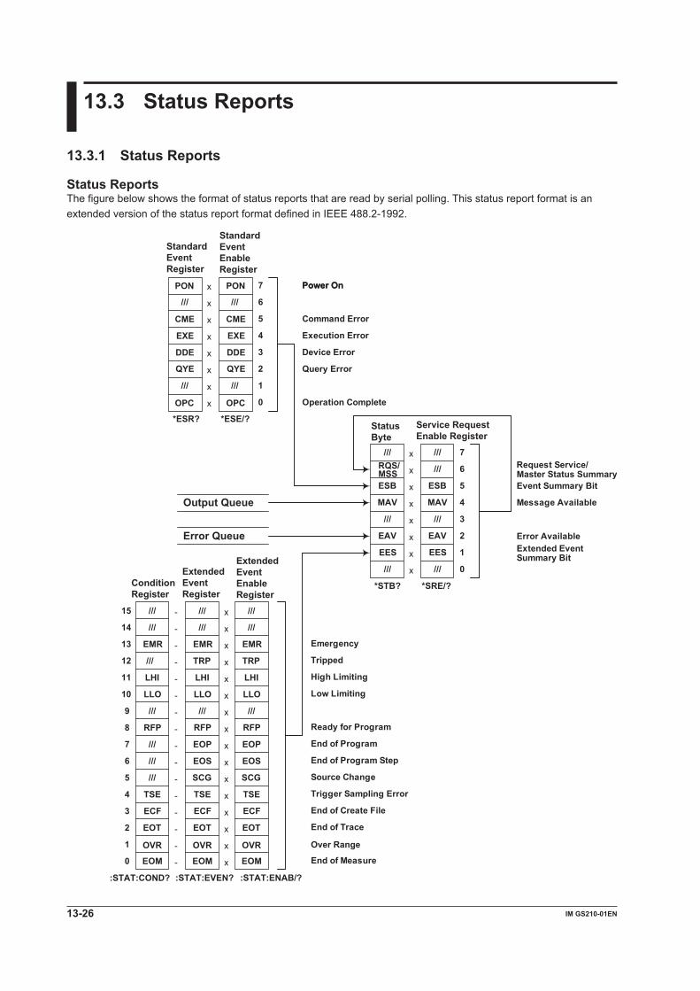
13-26 IM GS210-01EN
13.3 Status Reports
13.3.1 Status Reports
Status ReportsThe figure below shows the format of status reports that are read by serial polling. This status report format is an extended version of the status report format defined in IEEE 488.2-1992.
PON
///
CME
EXE
DDE
QYE
///
OPC
PON
///
CME
EXE
DDE
QYE
///
OPC
x
x
x
x
x
x
x
x
///RQS/MSSESB
MAV
///
EAV
EES
x
x
x
x
x
x
x
x
*ESR? *ESE/?
7
6
5
4
3
2
1
0
///
ESB
MAV
///
EAV
EES
7
6
5
4
3
2
1
0
Output Queue
Error Queue
*STB? *SRE/?
///
EMR
TRP
LHI
LLO
EOP
x
x
x
x
x
x
x
x
EOS
///
EMR
TRP
LHI
LLO
EOP
EOS
///
EMR
///
LHI
LLO
RFP
///
///
-
-
-
-
-
-
-
-
15
9
8
x
x
x
x
x
x
x
x
TSE
ECF
///
EOT-
-
-
-
-
-
-
-
7
6
5
4
3
2
1
0
:STAT:EVEN? :STAT:ENAB/?
Power On
///
EOM
TSE
ECF
///
EOT
///
EOM
TSE
ECF
///
EOT
///
EOM
10
11
12
14
13
RFP RFP
/// SCG SCG
///
///
///ConditionRegister
Extended Event Register
Extended EventEnableRegister
StatusByte
Service RequestEnable Register
Standard EventRegister
Standard EventEnable Register
:STAT:COND?
OVR OVR OVR
Emergency
Tripped
High Limiting
Low Limiting
Ready for Program
End of Program
Power On
Command Error
Execution Error
Device Error
Query Error
Operation Complete
Trigger Sampling Error
End of Trace
End of Measure
Request Service/Master Status SummaryEvent Summary Bit
Message Available
Error AvailableExtended EventSummary Bit
End of Program Step
Source Change
End of Create File
Over Range

13-27IM GS210-01EN
Com
munication C
omm
ands
3
2
1
4
5
6
7
8
9
10
11
12
13
14
15
App
Index
Overview of Registers and QueuesName Function Write ReadStatus byte — Serial polling (RQS),
*STB? (MSS)Service request enable register Status byte mask *SRE *SRE?Standard event register Indicates device status changes — *ESR?Standard event enable register Standard event register mask *ESE *ESE?Extended event register Indicates device status changes — :STATus:EVENt?Extended event enable register Extended event register mask :STATus:ENABle :STATus:ENABle?Condition register Current device status — :STATus:CONDition?Output queue Stores response messages for queries Query commands Same as leftError queue Stores error codes and error messages — :STATus:ERRor?
:SYSTem:ERRor?
Registers and Queues That Affect the Status ByteThe following registers affect the status byte bits.
Register Affected Status Byte BitStandard event register Bit 5 (ESB)Output queue Bit 4 (MAV)Error queue Bit 2 (EAV)Extended event register Bit 1 (EES)
Enable RegistersThe following registers are used to mask a bit so that the bit will not affect the status byte even when it is set to 1.
Masked Register Mask RegisterStatus byte Service request enable registerStandard event register Standard event enable registerExtended event register Extended event enable register
Reading and Writing to RegistersFor example, use the *ESE command to set the standard event enable register bits to 1 and 0. Use the *ESR? command to query whether the standard event register bits are 1 or 0. For details on these commands, see section 13.2.11.
13.3 Status Reports

13.3 Status Reports
13-28 IM GS210-01EN
13.3.2 Status Byte
Status Byte
7 6 5 4 3 2 1 0 RQS
MSS ESB MAV EAV EES
Bits 0, 3, and 7Not used (always 0)Bit 1 EES (Extended Event Summary Bit)This bit is set to 1 when the logical AND of the extended event register and the extended event enable register is 1. For details, see page 13-30.Bit 2 EAV (Error Available)This bit is set to 1 when the error queue is not empty. For details, see page 13-31.Bit 4 MAV (Message Available)This bit is set to 1 when the output queue is not empty. For details, see page 13-31.Bit 5 ESB (Event Summary Bit)This bit is set to 1 when the logical AND of the standard event register and the standard event enable register is 1. For details, see page 13-29.Bit 6 RQS (Request Service)/MSS (Master
Status Summary)This bit is set to 1 when the logical AND of the status byte excluding bit 6 and the service request enable register is 1. RQS is set to 1 when the MSS bit changes from 0 to 1 and is cleared when serial polling is carried out or when the MSS bit changes to 0.
Bit MaskingTo mask a bit in the status byte so that it does not cause an SRQ, set the corresponding bit of the service request enable register to 0.For example, to mask bit 2 (EAV) so that service is not requested when an error occurs, set bit 2 of the service request enable register to 0. Do this using the *SRE command. To query whether each bit of the service request enable register is 1 or 0, use *SRE?. For details on the *SRE command, see section 13.2.11.
Status Byte OperationA service request is issued when bit 6 in the status byte becomes 1. Bit 6 is set to 1 when any other bit becomes 1 (when the corresponding bit of the service request enable register is also set to 1).For example, if an event occurs and the logical OR of a standard event register bit and its corresponding enable register bit is 1, then bit 5 (ESB) is set to 1. At this point, if bit 5 of the service request enable register is 1, bit 6 (MSS) is set to 1, and the GS200 requests service from the controller.You can check what type of event occurred by reading the contents of the status byte.
Reading the Status ByteThere are two ways to read the contents of the status byte.*STB? QueryBit 6 functions as MSS when a query is made using *STB?. This causes the MSS to be read. This query does not cause any of the status byte bits to be cleared after the status byte is read.Serial PollingSerial polling causes bit 6 to function as an RQS bit. This causes the RQS to be read. After the status byte is read, only the RQS bit is cleared. You cannot read the MSS bit when serial polling is used.
Clearing the Status ByteThere is no way to clear all the bits in the status byte. The bits that are cleared for each operation are shown below.*STB? QueryNone of the bits are cleared.Serial PollingOnly the RQS bit is cleared.When a *CLS command is receivedWhen a *CLS command is received, the status byte itself is not cleared, but the contents of the standard event register, which affects the bits in the status byte, are cleared. As a result, the corresponding status byte bits are cleared. Because the output queue is not cleared with a *CLS command, bit 4 (MAV) in the status byte is not affected. However, the output queue will also be cleared if the *CLS command is received just after a program message terminator.

13.3 Status Reports
13-29IM GS210-01EN
Com
munication C
omm
ands
3
2
1
4
5
6
7
8
9
10
11
12
13
14
15
App
Index
13.3.3 Standard Event Register
Standard Event Register6
PON 7 5 4 3 2 1 0
CME EXE DDE QYE OPC
Bits 1 and 6Not used (always 0)Bit 0 OPC (Operation Complete)After the GS200 receives the *OPC command (see section 13.2.11), this bit is set to 1 when the operation specified by the *OPC command completes.Bit 2 QYE (Query Error)This bit is set to 1 when a query command is received, but the output queue is empty or the data is lost.Bit 3 DDE (Device Error)This bit is set to 1 when a command cannot be executed for internal reasons other than a command syntax error or command execution error.Bit 4 EXE (Execution Error)This bit is set to 1 when the command syntax is correct, but the command cannot be executed in the current state.Bit 5 CME (Command Error)This bit is set to 1 when there is a command syntax error.Bit 7 PON (Power On)This bit is set to 1 when the GS200 turns on.
Bit MaskingTo mask a certain bit of the standard event register so that it does not cause bit 5 (ESB) in the status byte to change, set the corresponding bit of the standard event enable register to 0.For example, to mask bit 2 (QYE) so that ESB will not be set to 1 even if a query error occurs, set bit 2 of the standard event enable register to 0. Do this using the *ESE command. To query whether each bit of the standard event enable register is 1 or 0, use *ESE?. For details on the *ESE command, see section 13.2.11.
Standard Event Register OperationThe standard event register indicates six types of events that occur inside the GS200. When one of the bits in this register is 1 (and the corresponding bit of the standard event enable register is also 1), bit 5 (ESB) in the status byte is set to 1.Example
1. A query error occurs.2. Bit 2 (QYE) is set to 1.3. When bit 2 of the standard event enable register
is 1, bit 5 (ESB) in the status byte is set to 1.You can also check what type of event occurred in the GS200 by reading the contents of the standard event register.
Reading the Standard Event RegisterYou can use the *ESR? command to read the contents of the standard event register. The register is cleared after it is read.
Clearing the Standard Event RegisterThe standard event register is cleared in the following three cases.• When the contents of the standard event register
are read using the *ESR command.• When a *CLS command is received• When the GS200 is restarted.

13.3 Status Reports
13-30 IM GS210-01EN
13.3.4 Extended Event Register
Extended Event Register
EMR
EMR
LHI
LHI
LLO
LLO TRP RFP
ECF
ECF
EOT
EOT TSE EOM Extended Event Register :STATus:EVENt?
Condition Register :STATus:CONDition?
14 15 13 12 11 10 9 8
14 15 13 12 11 10 9 8 SCG
6 7 5 4 3 2 1 0
6 7 5 4 3 2 1 0
TSE
EOS EOP
RFP EOM OVR
OVR
Each bit in the extended event register that has a corresponding bit in the condition register is set to 1 when the corresponding bit in the condition register changes from 0 to 1.
Bits 9, 14, and 15Not used (always 0)Bit 0 EOM (End of measure)The condition register bit is set to 0 when the GS200 is performing measurement and set to 1 when the GS200 is not performing measurement.Bit 1 OVR (Over range)The condition register bit is set to 1 when the measured result is outside of the allowable range and set to 0 when the measured result is within the allowable range.Bit 2 EOT (End of trace)The condition register bit is set to 0 when the GS200 is performing storage and set to 1 when the GS200 is not performing storage.Bit 3 ECF (End of create file)The condition register bit is set to 0 when GS200 is creating the storage result file and set to 1 when the GS200 is not creating the storage result file.Bit 4 TSE (Trigger sampling error)The condition register bit is set to 0 when there is a trigger sampling error and set to 1 when there are no trigger sampling errors.Bit 5 SCG (Source change)The extended event register bit is set to 1 when the GS200’s source value changes.Bit 6 EOS (End of program step)The extended event register bit is set to 1 when a program step completes execution.Bit 7 EOP (End of program)The extended event register bit is set to 1 when a program completes execution.Bit 8 RFP (Ready for program)The condition register bit is set to 0 when the GS200 is getting ready to execute a program and set to 1 when the GS200 is not getting ready to execute a program.
Bit 10 LLO (Low limiter)The condition register bit is set to 1 when the GS200’s low limiter has activated and is set to 0 when the GS200’s low limiter has not activated.Bit 11 LHI (High limiter)The condition register bit is set to 1 when the GS200’s high limiter has activated and set to 0 when the GS200’s high limiter has not activated.Bit 12 TRP (Tripped)The extended event register bit is set to 1 when the GS200 output trips.Bit 13 EMR (Emergency)The condition register bit is set to 1 when an abnormal temperature has been detected and the GS200 needs to be turned off.
Bit MaskingTo mask a certain bit of the extended event register so that it does not cause bit 1 (ESS) in the status byte to change, set the corresponding bit of the extended event enable register to 0. Do this using the :STATus:ENABle command.
Extended Event Register and Condition Register OperationThe extended event register indicates thirteen types of events that occur inside the GS200. When one of the bits in this register is 1 (and the corresponding bit of the extended event enable register is also 1), bit 1 (EES) in the status byte is set to 1.Example
1. A program completes execution.2. Bit 7 (EOP) is set to 1.3. When bit 7 of the extended event enable register
is 1, bit 1 (EES) in the status byte is set to 1.You can also check what type of event occurred in the GS200 by reading the contents of the extended event register.The condition register indicates nine types of events that occur inside the GS200. You can check the internal condition of the GS200 by reading the contents of the condition register.

13.3 Status Reports
13-31IM GS210-01EN
Com
munication C
omm
ands
3
2
1
4
5
6
7
8
9
10
11
12
13
14
15
App
Index
Reading the Extended Event Register and Condition RegisterYou can use the :STATus:EVENt? command to read the contents of the extended event register. The register is cleared after it is read. You can use the :STATus:CONDition? command to read the contents of the condition register. The register does not change even if it is read.
Clearing the Extended Event RegisterThe extended event register is cleared in the following three cases.• When the contents of the extended event register
are read using the :STATus:EVENt? command.• When a *CLS command is received• When the GS200 is restarted.
13.3.5 Output Queue and Error Queue
Output QueueThe output queue stores query response messages.As shown below, data is stored in order and read from the oldest message first. The output queue is cleared in the following cases.• When a new message is received from the
controller.• When a deadlock occurs (see page 13-3).• When a device clear command (DCL or SDC) is
received.• When the GS200 is restarted.The *CLS command does not clear the output queue. You can determine whether or not the output queue is empty by checking bit 4 (MAV) in the status byte.
D1 D2 D1 D2
D1
Error QueueWhen an error occurs, the error queue stores the error number and message. For example, if the GS200 receives an incorrect program message from the controller, the error number (–113) and the error message (“Undefined header”) are stored in the error queue when the GS200 displays the error message.You can use the :SYSTem:ERRor? query to read the contents of the error queue. Like the output queue, the messages in the error queue are read from the oldest one first.If the error queue overflows, the last message is replaced with the following message: –350, “Queue overflow.”The error queue is cleared in the following cases.• When a *CLS command is received.• When the GS200 is restarted.You can determine whether or not the error queue is empty by checking bit 2 (EAV) in the status byte.
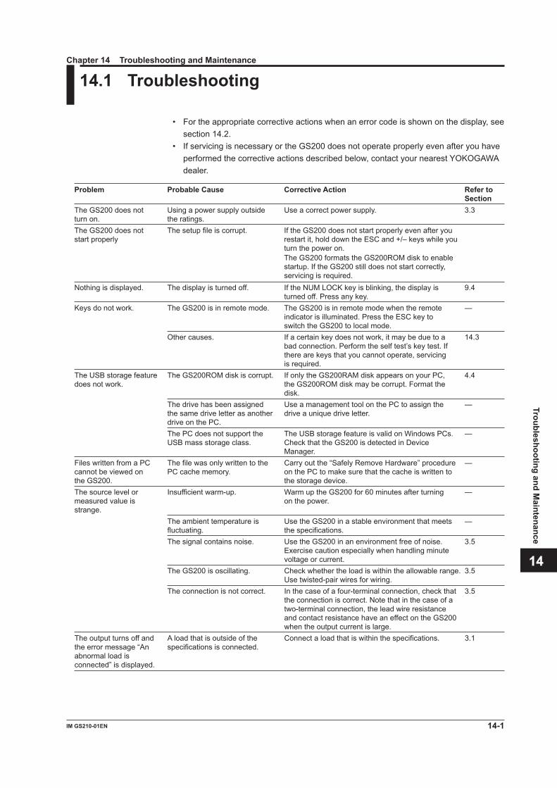
3
2
1
4
5
6
7
8
9
10
11
12
13
14
15
App
Index
14.1 Troubleshooting
• For the appropriate corrective actions when an error code is shown on the display, see section 14.2.
• If servicing is necessary or the GS200 does not operate properly even after you have performed the corrective actions described below, contact your nearest YOKOGAWA dealer.
Problem Probable Cause Corrective Action Refer to SectionThe GS200 does not Using a power supply outside Use a correct power supply. 3.3 turn on. the ratings. The GS200 does not The setup file is corrupt. If the GS200 does not start properly even after you start properly restart it, hold down the ESC and +/– keys while you turn the power on. The GS200 formats the GS200ROM disk to enable
startup. If the GS200 still does not start correctly, servicing is required.
Nothing is displayed. The display is turned off. If the NUM LOCK key is blinking, the display is 9.4 turned off. Press any key.
Keys do not work. The GS200 is in remote mode. The GS200 is in remote mode when the remote — indicator is illuminated. Press the ESC key to switch the GS200 to local mode.
Other causes. If a certain key does not work, it may be due to a 14.3 bad connection. Perform the self test’s key test. If there are keys that you cannot operate, servicing is required.
The USB storage feature The GS200ROM disk is corrupt. If only the GS200RAM disk appears on your PC, 4.4 does not work. the GS200ROM disk may be corrupt. Format the disk. The drive has been assigned Use a management tool on the PC to assign the — the same drive letter as another drive a unique drive letter. drive on the PC. The PC does not support the The USB storage feature is valid on Windows PCs. — USB mass storage class. Check that the GS200 is detected in Device Manager. Files written from a PC The file was only written to the Carry out the “Safely Remove Hardware” procedure — cannot be viewed on PC cache memory. on the PC to make sure that the cache is written to the GS200. the storage device. The source level or Insufficient warm-up. Warm up the GS200 for 60 minutes after turning — measured value is on the power. strange. The ambient temperature is Use the GS200 in a stable environment that meets — fluctuating. the specifications. The signal contains noise. Use the GS200 in an environment free of noise. 3.5 Exercise caution especially when handling minute voltage or current. The GS200 is oscillating. Check whether the load is within the allowable range. 3.5 Use twisted-pair wires for wiring. The connection is not correct. In the case of a four-terminal connection, check that 3.5 the connection is correct. Note that in the case of a two-terminal connection, the lead wire resistance and contact resistance have an effect on the GS200 when the output current is large. The output turns off and A load that is outside of the Connect a load that is within the specifications. 3.1 the error message “An specifications is connected. abnormal load is connected” is displayed.
Chapter 14 Troubleshooting and Maintenance
14-1IM GS210-01EN
Troubleshooting and Maintenance

Problem Probable Cause Corrective Action Refer to Section“Abnormal Temperature” The vent or inlet holes are Provide adequate space around the GS200. 3.1, 3.2 is displayed. blocked. Unable to save data to No free space on the disk. Delete unneeded files or format the disk. 4.4 the disk. Unable to use the Communication settings on Match the GS200’s communication settings with Chapters communication interface the GS200 and PC do not match. those on the PC. 10 to 12 to set the GS200.
14.1 Troubleshooting
14-2 IM GS210-01EN
3
2
1
4
5
6
7
8
9
10
11
12
13
14
15
App
Index
14.2 Error Code Descriptions and Corrective Actions
The following two types of messages can appear in the center of the display or the error log view.• Error messages (Error) Error messages are displayed when an inappropriate operation is carried out.• Confirmation messages Confirmation messages are not entered in the error queue, but they are displayed in
the error log.
Syntax Errors (–100 to –199)Error No. Error Message Corrective Action Page–100 Command error Check whether the command string is incorrect. —–101 Invalid_character Check whether invalid characters such as $ or & are — used in the command header or parameters. –102 Syntax_error Check that the syntax is correct. —–103 Invalid separator Check the use of the separator (comma). —–106 Parameter not allowed Check the command and the number of parameters. —–107 Missing parameter Check the command and the number of parameters. —–113 Undefined header Check the command mnemonic. —–121 Invalid character in number Check that the notation of the numeric parameter is 13-5 correct (for example, binary notation should not contain characters other than 0 and 1). –123 Exponent too large Check whether the exponent is within the range of — –127 to 127. –128 Numeric data not allowed Check the parameter format. —–131 Invalid suffix Check the unit that can be used for the parameter. —–138 Suffix not allowed Check the parameter format. —–141 Invalid character data Check the character data that can be used for the — parameter. –148 Character data not allowed Check the command and parameter format. —–150 String data error Check that all strings have closing quotation marks — (“ or ’).–151 Invalid string data Check that string parameters are in the correct format. —–158 String data not allowed Check the command and parameter format. —–160 Block data error Check that block data is correct. —–161 Invalid block data Check that block data is in the correct format. —–168 Block data not allowed Check the command and parameter format. —–170 Expression error Check the command and parameter format. —–178 Expression data not allowed Check the command and parameter format. —
14-3IM GS210-01EN
Troubleshooting and Maintenance

Execution Errors (–200 to –299)Error No. Error Message Corrective Action Page–203 Command Protected Check the command mnemonic. —–220 Parameter error Check the length of each parameter. —–222 Data out of range Check the range of the parameters. If the command — can use MINimum or MAXimum for its parameters, the range can also be queried. –224 Illegal parameter Check the parameter format. —–250 Mass storage error Format the ROM disk. If you cannot format the disk, 4-8 servicing is necessary. –256 Filename not found Check that the file exists. You can also use the 13-14, CATalog? command to query the list of files. 13-21–284 Program currently running Stop the program that is currently running. —–285 Program syntax error Check that the program file is in the correct format. 2-13–286 Program runtime error You cannot stop a program that has already been 6-12 stopped.
Device Errors (–300 to –399)Error No. Error Message Corrective Action Page–311 Memory error Restart the GS200. If the error still appears, servicing — is necessary. –320 Storage fault Format the disk. If you cannot format the disk, 4-8 servicing is necessary. –350 Queue overflow Use :SYSTem:ERRor? to read the error, or use 13-22, *CLS to clear the error queue. 13-24
Query Errors (–400 to –499)Error No. Error Message Corrective Action Page–410 Query INTERRUPTED Check the transmission and reception order. 13-3
14.2 Error Code Descriptions and Corrective Actions
14-4 IM GS210-01EN

3
2
1
4
5
6
7
8
9
10
11
12
13
14
15
App
Index
Instrument Errors (100 and higher)Error No. Error Message Corrective Action Page100 Program is not defined Select a different program file, or edit the program, 6-5 and then run it. 101 Program is not being edited You can only end program editing when a program 6-5 is being edited. 103 Program is being edited You cannot change GS200 settings or run a 6-5 program when a program is being edited. 104 Illegal file Check that the file is correct. 6-9, 9-2, 105 CSV format may be incorrect Check the CSV-format setting. 9-6106 Trigger source is M.End When the trigger is M.End, you cannot use RUN 6-4 and STEP to perform program execution. 107 Stopped because function has changed Change the source function to match the program, 6-5 and execute the program again. 108 Turn OUTPUT on to execute program Turn output on to execute the program. 6-12109 Illegal calibration Servicing is necessary. —110 Illegal program function Make sure that a program only contains the same — functions.111 Illegal zero calibration Servicing is necessary. —200 Power-on setup lost There is no setup file. Specify the setup file 9-4 correctly.201 Failed to read serial number Restart the GS200. — If the error still appears, servicing is necessary.202 Failed to read system parameters Settings such as the communication settings have — been reset to the factory default settings, so set them back to the correct settings. If the same error continues to appear, servicing is required. 203 Cannot save file Check that there is data to save and that the file is 9-2 not set to read-only. 204 Cannot load file Check that there is a file to load and that the 9-2 contents of the file are correct. 205 Cannot delete file Check that there is a file to delete and that the file 9-2 is not set to read-only. 300 An abnormal load is connected Connect a load that is within the specifications. —303 Low battery Request to have the battery replaced, because the — timestamp when creating files will not be correct. 304 Failed to detect the line frequency Make sure that the power source is stable, and — restart the GS200. 500 Storing has not finished yet Wait for the storage operation to complete (the 7-8 EOT bit becomes 1) before you start it again. 600 CPU board error Restart the GS200. If the error still appears, — 601 servicing is necessary. When you send the GS200 602 off for servicing, inform the service technician of 603 the error number. 604
14.2 Error Code Descriptions and Corrective Actions
14-5IM GS210-01EN
Troubleshooting and Maintenance

14.3 Self-Test
ProcedureDisplaying the Self-Test Menu
1. Press UTILITY to display the following menu.
2. Press the Sys Config soft key to display the following menu.
3. Press the Test soft key.
Executing the Display Test4. Press the Display Test soft key. The entire display and the SAMPLE ERROR
indicator illuminate.
5. Press RANGE to turn off the entire display. Press RANGE to illuminate the entire display.
6. When you press one of the keys that are below the display, the indicators at the top of the front panel illuminate in the following order. The indicators illuminate in the reverse order each time that you press one of the keys.
SAMPLE ERRORREPEATSTOREREMOTEERRORThe OUTPUT keyThe NUM LOCK key
7. Press ESC to end the test.
Executing the Key Test4. Press the Key Test soft key.
14-6 IM GS210-01EN
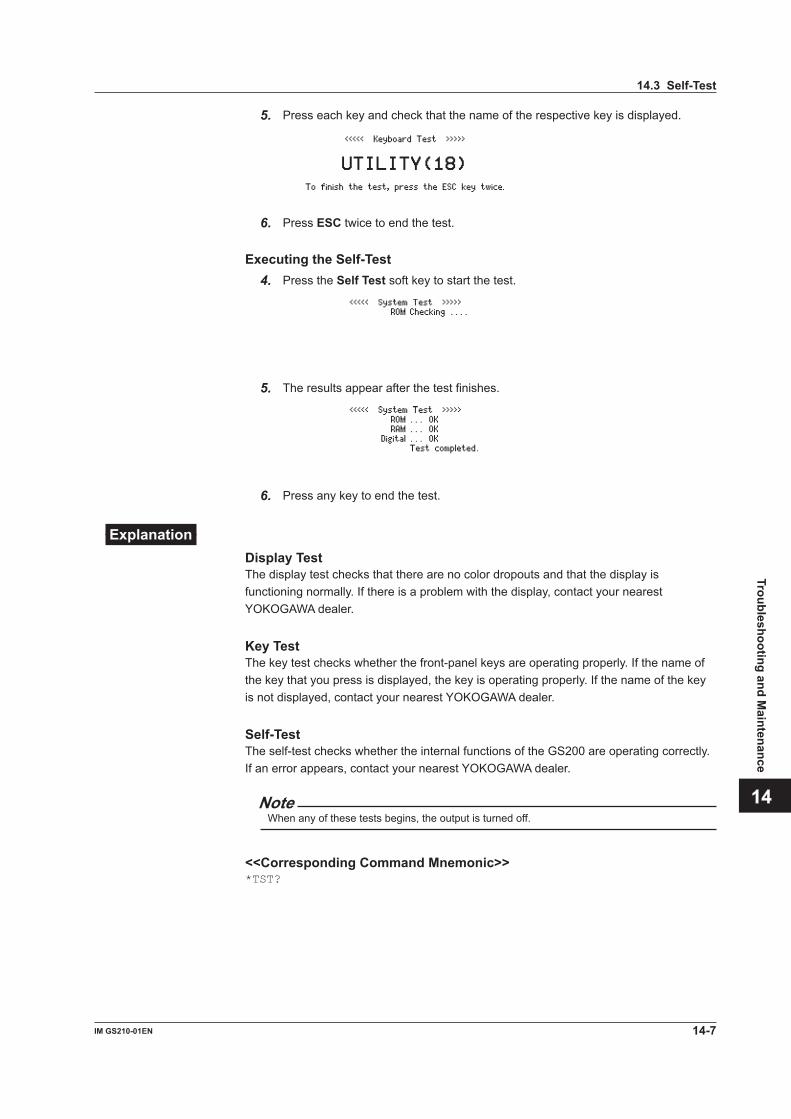
3
2
1
4
5
6
7
8
9
10
11
12
13
14
15
App
Index
5. Press each key and check that the name of the respective key is displayed.
6. Press ESC twice to end the test.
Executing the Self-Test4. Press the Self Test soft key to start the test.
5. The results appear after the test finishes.
6. Press any key to end the test.
ExplanationDisplay TestThe display test checks that there are no color dropouts and that the display is functioning normally. If there is a problem with the display, contact your nearest YOKOGAWA dealer.
Key TestThe key test checks whether the front-panel keys are operating properly. If the name of the key that you press is displayed, the key is operating properly. If the name of the key is not displayed, contact your nearest YOKOGAWA dealer.
Self-TestThe self-test checks whether the internal functions of the GS200 are operating correctly. If an error appears, contact your nearest YOKOGAWA dealer.
NoteWhen any of these tests begins, the output is turned off.
<<Corresponding Command Mnemonic>>*TST?
14.3 Self-Test
14-7IM GS210-01EN
Troubleshooting and Maintenance
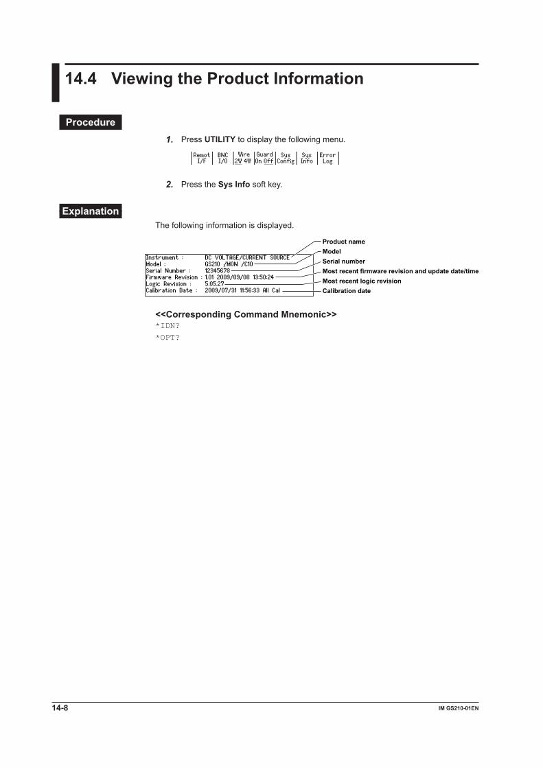
14.4 Viewing the Product Information
Procedure1. Press UTILITY to display the following menu.
2. Press the Sys Info soft key.
ExplanationThe following information is displayed.
Product name
Serial numberMost recent firmware revision and update date/timeMost recent logic revision
Model
Calibration date
<<Corresponding Command Mnemonic>>*IDN?
*OPT?
14-8 IM GS210-01EN
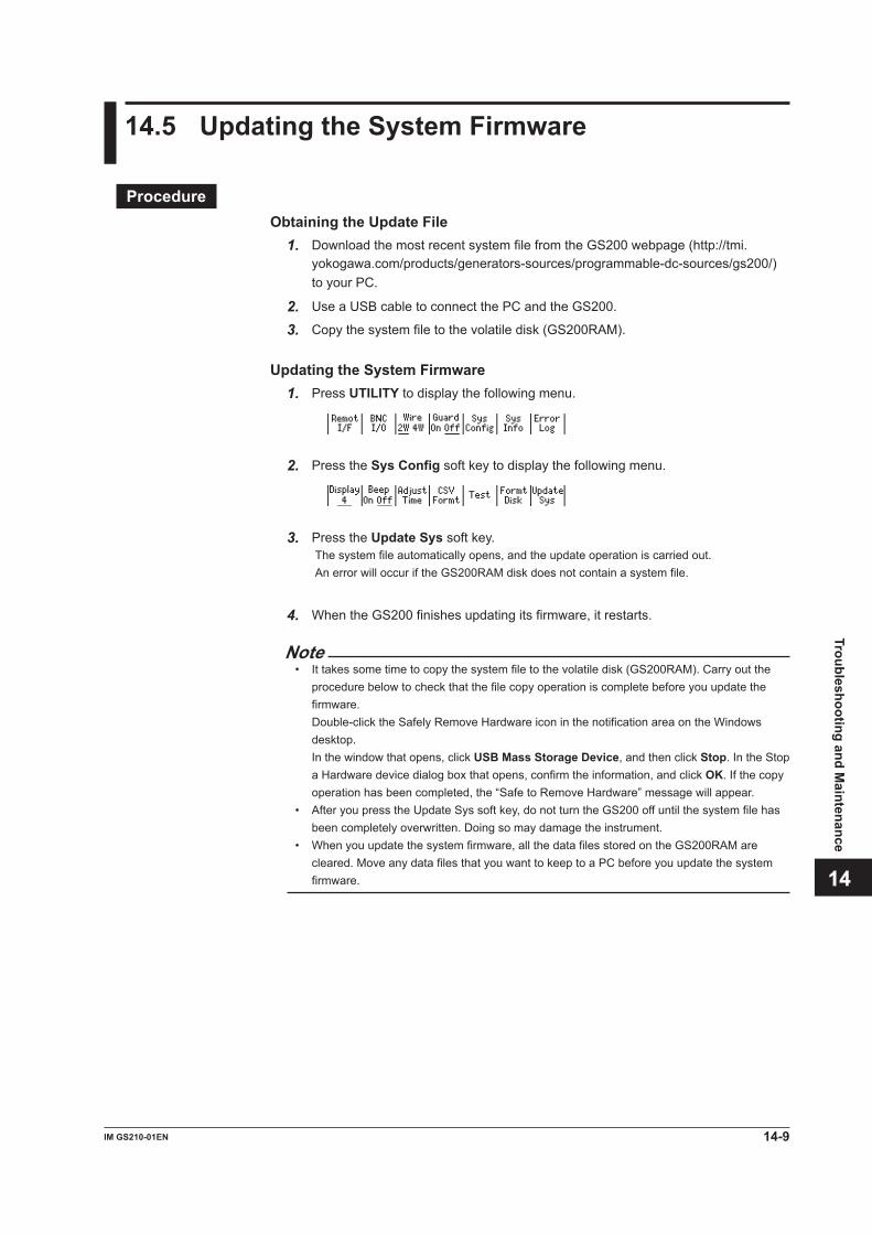
3
2
1
4
5
6
7
8
9
10
11
12
13
14
15
App
Index
14.5 Updating the System Firmware
ProcedureObtaining the Update File
1. Download the most recent system file from the GS200 webpage (http://tmi.yokogawa.com/products/generators-sources/programmable-dc-sources/gs200/) to your PC.
2. Use a USB cable to connect the PC and the GS200.
3. Copy the system file to the volatile disk (GS200RAM).
Updating the System Firmware1. Press UTILITY to display the following menu.
2. Press the Sys Config soft key to display the following menu.
3. Press the Update Sys soft key. The system file automatically opens, and the update operation is carried out. An error will occur if the GS200RAM disk does not contain a system file.
4. When the GS200 finishes updating its firmware, it restarts.
Note• It takes some time to copy the system file to the volatile disk (GS200RAM). Carry out the
procedure below to check that the file copy operation is complete before you update the firmware.
Double-click the Safely Remove Hardware icon in the notification area on the Windows desktop.
In the window that opens, click USB Mass Storage Device, and then click Stop. In the Stop a Hardware device dialog box that opens, confirm the information, and click OK. If the copy operation has been completed, the “Safe to Remove Hardware” message will appear.
• After you press the Update Sys soft key, do not turn the GS200 off until the system file has been completely overwritten. Doing so may damage the instrument.
• When you update the system firmware, all the data files stored on the GS200RAM are cleared. Move any data files that you want to keep to a PC before you update the system firmware.
14-9IM GS210-01EN
Troubleshooting and Maintenance
ExplanationYou must store the most recent system file on the GS200RAM before you update the system firmware.You can download the system file from the YOKOGAWA website at the following URL: http://tmi.yokogawa.com/products/generators-sources/programmable-dc-sources/gs200/
The webpage listed above also contains information about useful applications for use with the GS200.
14.5 Updating the System Firmware
14-10 IM GS210-01EN

3
2
1
4
5
6
7
8
9
10
11
12
13
14
15
App
Index
14.6 Changing the Power Fuse
WARNING• To prevent fire, only use a fuse that matches the designated rated values (current,
voltage, and type).• Always turn the GS200 off and remove the power cord before you change the
fuse.• Do not short the fuse holder.
French
AVERTISSEMENT• Pour éviter tout incendie, utiliser un fusible adapté aux valeurs nominales
indiquées (courant, tension et type).• Couper GS200 et débrancher le câble d’alimentation avant de remplacer le
fusible.• Ne jamais mettre le porte-fusible en court-circuit.
Designated Rated ValuesThe type of fuses that the GS200 uses are described below.
Suffix Code/Rated Supply Voltage: -1 (100 VAC) or -4 (120 VAC)• Maximum rated voltage: 250 V• Maximum rated current: 1 A• Type: Time lag• Standard: UL/VDE certification• Part number: A1109EF
Suffix Code/Rated Supply Voltage: -7 (230 VAC)• Maximum rated voltage: 250 V• Maximum rated current: 0.5 A• Type: Time lag• Standard: UL/VDE certification• Part number: A1108EF
14-11IM GS210-01EN
Troubleshooting and Maintenance
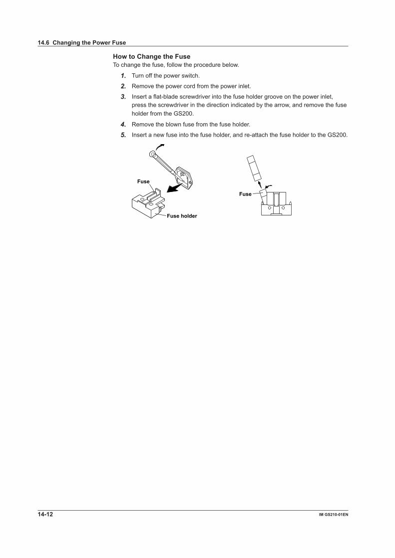
How to Change the FuseTo change the fuse, follow the procedure below.
1. Turn off the power switch.
2. Remove the power cord from the power inlet.
3. Insert a flat-blade screwdriver into the fuse holder groove on the power inlet, press the screwdriver in the direction indicated by the arrow, and remove the fuse holder from the GS200.
4. Remove the blown fuse from the fuse holder.
5. Insert a new fuse into the fuse holder, and re-attach the fuse holder to the GS200.
Fuse holder
Fuse
Fuse
14.6 Changing the Power Fuse
14-12 IM GS210-01EN
3
2
1
4
5
6
7
8
9
10
11
12
13
14
15
App
Index
14.7 Recommended Replacement Parts and Maintenance
Recommended Replacement PartsThe life and replacement period for expendable items varies depending on the conditions of use. Refer to the table below as a general guideline.For part replacement and purchase, contact your nearest YOKOGAWA dealer.
Part Name Recommended Replacement PeriodCooling fan 3 yearsBackup battery (lithium battery) 5 yearsVFD 3 yearsSource output relay Electrical life: Approximately 100,000 operations
CalibrationWe recommend that you calibrate the GS200 once a year to assure its accuracy. Contact your nearest YOKOGAWA dealer to have your GS200 calibrated.
14-13IM GS210-01EN
Troubleshooting and Maintenance

15.1 Source Section
DC Voltage SourceRange Range Resolution 24 h Stability 90-Day Stability 90-Day Accuracy 1-Year Accuracy Temperature Generated ±(% of setting ±(% of setting ±(% of setting ±(% of setting Coefficient + µV) + µV) + μV) + μV) ±(% of setting + μV)/°C10 mV ±12.0000 mV 100 nV 0.002 + 3 0.014 + 4 0.018 + 4 0.025 + 5 0.0018 + 0.7100 mV ±120.000 mV 1 μV 0.003 + 3 0.014 + 5 0.018 + 10 0.025 + 10 0.0018 + 0.71 V ±1.20000 V 10 μV 0.001 + 10 0.008 + 50 0.010 + 100 0.016 + 120 0.0009 + 710 V ±12.0000 V 100 μV 0.001 + 20 0.008 + 100 0.010 + 200 0.016 + 240 0.0008 + 1030 V ±32.000 V 1 mV 0.001 + 50 0.008 + 200 0.010 + 500 0.016 + 600 0.0008 + 3024 h stability is for 23°C ±1°C and when the voltage variation is within ±5%.90-day stability and 90-day and 1-year accuracy values are for 23°C ± 5°C.Add the temperature coefficient for 90-day and 1-year accuracy values for 5°C to 18°C and for 28°C to 40°C.
Range Maximum Output Current Output Resistance Output Noise DC to 10 Hz DC to 10 kHz (Reference)10 mV ---- Approx. 2 Ω 3 μVp-p 30 μVp-p100 mV ---- Approx. 2 Ω 5 μVp-p 30 μVp-p1 V ±200 mA 2 mΩ or less 15 μVp-p 60 μVp-p10 V ±200 mA 2 mΩ or less 50 μVp-p 100 μVp-p30 V ±200 mA 2 mΩ or less 150 μVp-p 200 μVp-pOutput noise is for when measurements are turned off.
Common mode rejection ratio: 120 dB or higher (DC, 50/60 Hz)(100 dB or higher for 30 V range)
DC Current SourceRange Range Resolution 24 h Stability 90-Day Stability 90-Day Accuracy 1-Year Accuracy Temperature Generated ±(% of setting ±(% of setting ±(% of setting ±(% of setting Coefficient + µA) + µA) + µA) + µA) ±(% of setting + µA)/°C1 mA ±1.20000 mA 10 nA 0.0015 + 0.03 0.016 + 0.1 0.02 + 0.1 0.03 + 0.1 0.0015 + 0.0110 mA ±12.0000 mA 100 nA 0.0015 + 0.3 0.016 + 0.5 0.02 + 0.5 0.03 + 0.5 0.0015 + 0.1100 mA ±120.000 mA 1 μA 0.004 + 3 0.016 + 5 0.02 + 5 0.03 + 5 0.002 + 1200 mA ±200.000 mA 1 μA 0.004 + 20 0.016 + 30 0.02 + 30 0.03 + 30 0.002 + 524 h stability is for 23°C ±1°C and when the voltage variation is within ±5%.90-day stability and 90-day and 1-year accuracy values are for 23°C ± 5°C.Add the temperature coefficient for 90-day and 1-year accuracy values for 5°C to 18°C and for 28°C to 40°C.
Range Maximum Output Voltage Output Resistance Output Noise DC to 10 Hz DC to 10 kHz (Reference)1 mA ±30 V 100 MΩ or higher 0.02 μAp-p 0.1 μAp-p10 mA ±30 V 100 MΩ or higher 0.2 μAp-p 0.3 μAp-p100 mA ±30 V 10 MΩ or higher 2 μAp-p 3 μAp-p200 mA ±30 V 10 MΩ or higher 10 μAp-p 15 μAp-pOutput noise is for when measurements are turned off.
Common mode rejection ratio: 100 nA/V or less (DC, 50/60 Hz)
Chapter 15 Specifications
15-1IM GS210-01EN
Specifications
3
2
1
4
5
6
7
8
9
10
11
12
13
14
15
App
Index

Item SpecificationsLimiter
Limiter Range ResolutionCurrent limiter (only in voltage source mode) 1 mA to 200 mA 1 mAVoltage limiter (only in current source mode) 1 V to 30 V 1 V
Response time (reference) 10 ms or less for all voltage source and current source ranges. The time for the output to reach within 0.1% of the final value after the output starts changing. Pure
resistive load. When the limiter is not enabled.LCload Capacitiveload:10μF.InductiveLoad:1mH.
15.1 Source Section
15-2 IM GS210-01EN

15.2 Measurement Section (On models with the /MON option)
DC Voltage MeasurementRange Measurement Resolution Input Resistance 1-Year Accuracy (1 PLC) Temperature Coefficient Range ±(% of reading + mV) ±(% of reading + mV)/°C30 V ±31.000 V 1 mV 10 MΩ or higher 0.02 + 2 0.002 + 0.1
DC Current MeasurementRange Measurement Resolution Input Resistance 1-Year Accuracy (1 PLC) Temperature Coefficient Range ±(% of reading + μA) ±(% of reading + μA)/°C200 mA ±210.00 mA 10 μA 2 mΩ or less 0.03 + 300 0.003 + 301 V, 10 V, 30 V source ranges only
15.3 Features
SourceItem SpecificationsFunction Voltage or current
ProgrammingItem SpecificationsMaximum number of steps 10000Program trigger External, internal timer, STEP key, or measurement end (M.End)Internal timer 0.1 s to 3600.0 sSlope 0 s to 3600.0 s
MeasurementItem SpecificationsFunction Voltage (current source mode) or current (voltage source mode)Integration time 1 PLC to 25 PLCTrigger Measurement timer (period: 0.1 s to 3600.0 s), measurement end, source change completion
(Ready), or communication commandMeasurement delay 0 ms to 999999 msStorage Up to 10000 resultsVoltage sense Two-wire system and four-wire systemAuto zero Measures the internal zero reference and uses it to correct the measured value for each
measurementNULL computation Displays the result obtained by subtracting the NULL value from the measured value
15-3IM GS210-01EN
Specifications
3
2
1
4
5
6
7
8
9
10
11
12
13
14
15
App
Index

15.4 External I/O Section (BNC (IN/OUT) and I/O for synchronous operation (SYNC IN/OUT))
BNC I/OItem SpecificationsConnector BNC connectorI/O level TTLI/O logic Negative logic, falling edgeMinimum pulse width 10 μsIN signal TRIG IN and OUTPUT INOUT signal TRIG OUT, OUTPUT OUT, and READY OUT
I/O for Synchronous OperationItem SpecificationsConnector RJ-11 connectorI/O level TTLMinimum pulse width 10 µsPinout
Pin No. SYNC IN SYNC OUT1 OUTPUT IN OUTPUT OUT2 NC NC3 TRIG IN TRIG OUT4 GND GND5 NC READY OUT6 NC *
* This pin is used for servicing the GS200. Do not use it.
15-4 IM GS210-01EN

15.5 Interface
GP-IB InterfaceItem SpecificationsElectrical and mechanical Conforms to IEEE St’d 488-1987 specificationsFunctional specifications SH1, AH1, T6, L4, SR1, RL1, PP0, DC1, DT1, and C0Protocol Conforms to IEEE St’d 488.2-1992Address 0 to 30
USB InterfaceItem SpecificationsNumber of ports 1Connector Type B connector (receptacle)Electrical and mechanical Conforms to USB 2.0 specificationsProtocol Mass storage class, USB-TMC
Ethernet InterfaceItem SpecificationsNumber of ports 1Connector RJ-45 connectorElectrical and mechanical Conforms to IEEE 802.3 specificationsTransmission system 100BASE-TX/10BASE-TData rate 100 Mbps/10 MbpsProtocol VXI-11 server, HTTP server, FTP server, DHCP client, and command socket
15-5IM GS210-01EN
Specifications
3
2
1
4
5
6
7
8
9
10
11
12
13
14
15
App
Index

15.6 General Specifications
Item SpecificationsDisplay 256 × 64 dots fluorescent tube (VFD)Internal memory GS200ROM: 4 MB (non-volatile; used to save setup files and program files) GS200RAM: 16 MB (volatile, cleared when the power is turned off; used to save the measured
results)Warm-up time Approx. 60 minutesStorage conditions Temperature –15°C to 60°C Humidity 20% RH to 80% RH (no condensation) Altitude 2000 m or lessOperating conditions Temperature 5°C to 40°C Humidity 20% RH to 80% RH (no condensation) Altitude 2000 m or lessRated supply voltage 100 VAC, 120 VAC, and 230 VACPermitted supply voltage Each rated voltage ± 10% rangeRated power supply 50/60 Hz frequencyPermitted power supply 48 Hz to 63 Hz frequency rangeMaximum allowable input Across OUTPUT Hi and OUTPUT Lo and across SENSE Hi and SENSE Lo ±32 Vpeakvoltage Across OUTPUT Lo and G terminal and across SENSE Lo and G terminal ±42 Vpeak Across each OUTPUT terminal and each SENSE terminal ±0.5 Vpeak Across G terminal and case ±250 VpeakMaximum power Approx. 80 VA consumptionMaximum common-mode Across each terminal and case ±250 Vpeak voltageExternal dimensions Approx. 213 (W) × 88 (H) × 379 (D) mm (excluding protrusions)Weight Approx. 5 kgRecommended calibration 1 year periodSafety standards Compliant standards EN 61010-1, EN 61010-2-030 Indoor use Measurement category Other (O) (250 Vpeak)1
Overvoltage category II2
Pollution degree 23
Emissions Compliant standards EN 61326-1 Class A EN 55011 Class A Group 1 EN 61000-3-2 EN 61000-3-3 EMC Regulatory Arrangement in Australia and New Zealand EN55011 Class A Group 1 Korea Electromagnetic Conformity Standard ( 한국 전자파적합성기준 ) This is a Class A product. Operation of this product in a residential area may cause radio interference in which case the
user is required to correct the interference. • Test conditions 1 V range, 1 V source, limit: ±200 mA, load resistance: 10 Ω, and local sense (2W) All other settings at factory default. Cable conditions • Output terminals Use the included measurement lead set (758933; red and black, one pc. each; length: 1 m) to
connect the OUTPUT terminals. We recommend that you use the same cables when connecting the SENSE terminals for four-
terminal connection. (Use cables that are 1 m in length or less.)
15-6 IM GS210-01EN

Item Specifications • BNC IN/OUT terminals Use cables that are at least equivalent to 1.5D-QEW cables when connecting the BNC
terminals.4
• ETHERNET port Use shielded (STP) LAN cables that are category 5 or better when connecting the
ETHERNET port. (Use cables that are 30 m in length or less.) • USB port Use cables that support USB 2.0 (Hi-speed USB) when connecting the USB port4
• GP-IB connector Use GP-IB cables (IEEE488) when connecting the GP-IB connector. • RJ-11 IN/OUT terminals Use shielded cables (758960, length: 1 m) when connecting the RJ-11 terminals.Immunity Compliant standards EN 61326-1 Table25
• Immunity influence Within the range specified by measured value ± 20% of range • Test conditions 1 V range, 1 V source, limit: ±200 mA, load resistance: 10 Ω, and local sense (2W) All other settings at factory default (the cable conditions were tested under the same
conditions as the emission test).Environmental standards6 EU RoHS Directive compliant* If you obtained this manual separately from the product, the specifications in this manual may differ from those of the product.1 The measurement category of the GS200 signal input terminals is Other (O). Do not use it to measure the main power supply
or for Measurement Categories II, III, and IV. Measurement category Other (O) applies to measurement of circuits that are not directly connected to a main power supply.
This category applies to measurement of secondary electric circuits in equipment across a transformer. The estimated transient overvoltage that may be applied to the GS200 signal input terminals is 1500 V.
Measurement category II applies to measurement of circuits, such as household electric appliances and portable electric tools, that are connected to low-voltage installations.
Measurement category III applies to measurement of facility circuits, such as distribution boards and circuit breakers. Measurement category IV applies to measurement of power source circuits, such as entrance cables to buildings and cable
systems, for low-voltage installations.2 The overvoltage category is a value used to define the transient overvoltage condition and includes the rated impulse
withstand voltage. Overvoltage category II applies to electrical equipment that is powered through a fixed installation, such as a switchboard.
3 Pollution Degree applies to the degree of adhesion of a solid, liquid, or gas which deteriorates withstand voltage or surface resistivity. Pollution Degree 2 applies to normal indoor atmospheres (with only non-conductive pollution).
4 Use cables of length 3 m or less.5 Immunity test requirements for equipment intended for use in industrial environments.6 For conformity to environmental regulations and/or standards other than EU, contact your nearest YOKOGAWA office (PIM113-
01Z2).
15.6 General Specifications
15-7IM GS210-01EN
Specifications
3
2
1
4
5
6
7
8
9
10
11
12
13
14
15
App
Index

15.7 External Dimensions
Unit : mm (approx. inch)
If not specified, the tolerance is ±3%. However, in cases of less than 10 mm, the tolerance is ±0.3 mm.
REAR VIEW
GS210
GS211
252.2 (9.93) 213
(8.39) 19.6
(0.77) (0.77)
( 178
.5)
( 7.0
3)
19.6
88
18.7
( 3
.46)
( 0
.74)
(2.89) (73.3) 350
(13.78) 28.5 (1.12)
Rack Mount (JIS) Panel Face 20
(0.79)
480±1
460±1
(18.90) (18.11)
( 3.9
0)
99 -0
.3
0
50 -0
.3
0
( 1.9
7)
Panel Face 20 (0.79)
( 3.9
0)
99 -0
.3
0
50 -0
.3
0
( 1.9
7)
24.5
( 0
.96)
24
.5
( 0.9
6)
480±1
460±1
(18.90) (18.11)
11
( 0.4
3)
6 ( 0
.24)
11
( 0
.43)
6 ( 0
.24)
482.6±1
460.3±1
(19.00) (18.12)
482.6±1
460.3±1
(19.00) (18.12)
7.1
( 0.2
8)
7.1
( 0.2
8)
20 (0.79)
20 (0.79)
Panel Face
Panel Face
( 3.4
6)
88 -0
.3
0
76.2
-0.3
0
( 3.0
0)
5.9
( 0.2
3)
( 3.4
6)
88 -0
.3
0
76.2
-0.3
0
( 3.0
0)
5.9
( 0.2
3)
Rack Mount (EIA)
15-8 IM GS210-01EN

Appendix 1 Factory Default Settings
Item Factory Default Setting
Saved When the GS200 Turns Off?
Saved to the Setup Data File?
SourceSource function Voltage No YesSource range 1 V No YesSource level 0 V No YesVoltage limiter 30 V No YesCurrent limiter 200 mA No YesOutput on/off Off No NoProgram file Unselected* No YesProgram repetition mode On No YesProgram interval time 0.1 s No YesProgram slope time 0.0 s No YesProgram trigger Norm No Yes
Measurement (Option)Measurement on/off On No YesMeasurement trigger Timer No YesMeasurement timer 0.1 s No YesIntegration time 1 PLC No YesMeasurement delay time 0 ms No YesNULL computation on/off Off No YesStorage on/off Off No NoStorage count 10000 No YesStorage file creation On No Yes
Wiring system 2W No YesGuard terminal Off No NoExternal I/O BNC IN terminal TRIG No Yes
BNC OUT terminal TRIG No YesCommunication
USB feature selection Storage* Yes NoGP-IB address 1* Yes NoGP-IB command mode GS200 mode* Yes NoDHCP on/off On* Yes NoIP address 0.0.0.0* Yes NoSubnet mask address 0.0.0.0* Yes NoDefault gateway address 0.0.0.0* Yes NoTransmission terminator CR+LF* Yes No
Other settingsFile that is loaded when the GS200 turns on
Unspecified* Yes No
Display brightness 4* Yes NoDisplay on/off On* No NoBeep sound on/off On* Yes NoDate and time Japan Standard
Time*Yes No
Time difference from GMT (Greenwich Mean Time)
+9:00* Yes No
CSV file format Decimal point: .* Yes NoDelimiter: ,* Yes No
* This setting is not initialized to its factory default setting when you initialize setup data (see section 9.1) or send the *RST command.
App-1IM GS210-01EN
Appendix
3
2
1
4
5
6
7
8
9
10
11
12
13
14
15
App
Index
Appendix

Appendix 2 Block Diagram
Analog sectionDigital section
VFD
LED
KEY
GP-IB I/F
LAN I/F
SYNC I/F
FPGA
SDRAM
CPU
DC/DC
Power SupplyAC/DC
USB I/F
AC/DC
ADC
+Limit DAC
-Limit DAC
Source DAC
PLD
Rs
DUTVo(VL)
Io(IL)
Power AMP
SW1 V
I
V
I
Vp
Vm
Vs
R1 R2
V/I
mV
V/I
mV
V/I V/I
mV mV
V/I
mV
SW2
SW2
R3
R4
FLASH ROM
SwitchControl
CurrentSense
VoltageSense
SENSE Hi
OUTPUT Hi
OUTPUT Lo
SENSE Lo
Limiter
The GS200 consists of a digital section that operates at ground potential and an analog section that is isolated from the digital section. The digital section consists of a CPU, FPGA, memory, and various interface circuits. A non-isolated DC-DC converter supplies power to the digital section. The digital section controls the display, keys, communications, and the analog section.The analog section consists of the voltage source’s D/A converters (DACs), an output amplifier, highly stable shunt resistors, and a limiter circuit. An isolated commercial transformer provides power to the analog section.Data that is sent from the digital section passes through a photocoupler and the PLD and controls each DAC and the various switches that are used for making range settings and other settings.When the GS200 is operating as a voltage source, SW1 is connected to V, and source voltage Vo is the product of source DAC value Vs and R2/R1. If load current IL increases positively and IL × Rs exceeds positive limiter DAC value Vp, the diode of the limiter circuit will turn on and suppress the load current to Vp/Rs. A similar operation takes place when the load current is negative.When the GS200 is operating as a current source, SW1 is connected to I, and source current Io is the product of source DAC value Vs and (R2/R1)/Rs. If load voltage VL exceeds positive limiter DAC value Vp, the diode of the limiter circuit will turn on and suppress the load voltage to Vp. A similar operation takes place when the load voltage is negative.The GS200 is equipped with a measurement circuit that is separate from the source and limiter circuits. In voltage source mode, the measurement circuit uses A/D converters (ADC) to measure the current that is received. In current source mode, the measurement circuit uses A/D converters (ADC) to measure the voltage that is received. Differing from the voltage and current source functions described above, when the mV range is selected in voltage source mode, SW2 is connected to mV. The source voltage Vo is voltage-divided by R3 and R4. In this situation, because the output resistance becomes R4 (2 Ω), if the DUT does not have a high impedance, the source voltage is reduced according to the DUT’s impedance. Additionally, because selecting mV causes the limiter and current measurement circuits to be disconnected by Rs and SW2 that are used for current sense, these circuits do not operate.
App-2 IM GS210-01EN

Index-1IM GS210-01EN
Index
3
2
1
4
5
6
7
8
9
10
11
12
13
14
15
App
Index
E Page
Edit Memory ........................................................................... 6-5ENTER ................................................................................... 1-5error code ............................................................................. 14-3Error Log................................................................................. 9-7error log display ...................................................................... 9-7ESC ................................................................................. 1-5, 4-2Ethernet ................................................................................ 2-27Ethernet interface ..................................................................11-1External ................................................................................ 2-20external dimensions.............................................................. 15-8external I/O ........................................................................... 2-24external trigger...................................................................... 2-20
F Page
factory default settings........................................................App-1firmware update .................................................................... 14-9Formt Disk .............................................................................. 4-8front panel............................................................................... 1-1FTP server feature .............................................2-27, 11-7, 11-11fuse ......................................................................................14-11fuse holder .......................................................................... 14-12
G Page
GP-IB address, setting ......................................................... 12-3GP-IB .................................................................................... 2-27GPIB ..................................................................................... 12-3GP-IB command mode ......................................................... 12-3GP-IB interface. .................................................................... 12-1Greenwich Mean Time.......................................................... 3-16GS200 .................................................................................. 12-3GS200RAM ................................................................... 2-26, 4-9GS200ROM ................................................................... 2-25, 4-9Guard...................................................................................... 4-5guard terminal................................................................ 2-10, 4-5
H Page
high limiter .............................................................................. 5-4HOLD............................................................................. 1-7, 6-12
I Page
Immed............................................................................ 2-21, 7-4initialization ............................................................................. 9-1Init Setup ................................................................................ 9-1installation conditions ............................................................. 3-5installation orientation ............................................................. 3-3integration time .............................................................. 2-17, 7-2Intvl ......................................................................................... 6-2IP address .............................................................................11-3IP Adrs ...................................................................................11-3
K Page
keypad mode .......................................................................... 4-1Key Test ................................................................................ 14-6
Index
Symbols Page
+/- ........................................................................................... 1-5
Numeric Page
2W .......................................................................................... 4-3two-terminal connection.......................................................... 4-34W .......................................................................................... 4-3four-terminal connection ......................................................... 4-37651...................................................................................... 12-3
A Page
accessories, optional ..................................................................vaccessories, standard................................................................ ivAdjust Time ........................................................................... 3-15Adjust Zero ........................................................................... 3-15Adrs ...................................................................................... 12-3
B Page
Beep ....................................................................................... 9-5beep sound ............................................................................. 9-5BNC IN ................................................................................... 8-1BNC I/O .................................................................................. 8-1BNC OUT ............................................................................... 8-1BNC I/O ................................................................................ 2-24BNC I/O terminals................................................................... 8-1
C Page
calibration ........................................................................... 14-13Clear ....................................................................................... 9-7Clear PwrOn ........................................................................... 9-4Clock..................................................................................... 3-15Comm ............................................................................ 2-21, 7-4commands, list of.................................................................. 13-7Count ...................................................................................... 7-8CSV Formt .............................................................................. 9-6CSV file format ....................................................................... 9-6current limiter ................................................................... 2-9, 5-4current source range ....................................................... 2-7, 5-2
D Page
Defalt Gatwy ..........................................................................11-4default gateway .....................................................................11-4default setting .....................................................................App-1Delay ...................................................................................... 7-3Delete File .............................................................................. 6-9Delete Setup ........................................................................... 9-3DHCP ....................................................................................11-3disk, formatting .............................................................. 2-26, 4-8Display .................................................................................... 9-5display brightness ................................................................... 9-5displayed contents .................................................................. 1-3display mode .......................................................................... 1-3Display Test .......................................................................... 14-6display, turning off ................................................................... 9-5

Index-2 IM GS210-01EN
L Page
LAN...............................................................................11-3, 11-6limit ......................................................................................... 5-4LIMIT ............................................................................... 1-6, 5-4limiter ............................................................................... 2-8, 5-4List Files .......................................................................... 6-8, 6-9Load File ................................................................................. 6-9Load Setup ............................................................................. 9-2LOCAL .................................................................................... 1-5local sense..................................................................... 2-10, 4-3low limiter ................................................................................ 5-4
M Page
mA ............................................................................1-6, 5-1, 6-5Meas ....................................................................................... 7-1Meas Config ......................................................7-2, 7-3, 7-4, 7-5MEASURE ............1-7, 7-1, 7-2, 7-3, 7-4, 7-5, 7-6, 7-7, 7-8, 7-10measured results .................................................................... 7-8measurement delay ....................................................... 2-17, 7-3measurement end.......................................................... 2-20, 6-4measurement end (immediate)...................................... 2-21, 7-4measurement function .......................................................... 2-16measurement operation........................................................ 2-16measurement range ............................................................. 2-16measurement timer.................................................2-21, 7-4, 7-5measurement trigger ............................................2-16, 2-21, 7-4measurement, turning off ........................................................ 7-1measurement, turning on........................................................ 7-1M.End ...................................................................2-12, 2-20, 6-4model ......................................................................................... iiimV ............................................................................1-6, 5-1, 6-5
N Page
network, connecting to...........................................................11-2network settings, viewing.......................................................11-6Norm .....................................................................2-12, 2-20, 6-4normal............................................................................ 2-20, 6-4Null ......................................................................................... 7-6NULL computation ................................................2-16, 2-17, 7-6NUM LOCK ...................................................................... 1-5, 4-1
O Page
offset calibration feature ....................................................... 2-17operating precautions ............................................................. 3-1OUTPUT .................................................................1-6, 5-5, 6-12output, on and off ............................................................. 2-8, 5-5output, tripping ...................................................................... 2-10OverView ...............................................................................11-6Over Write ....................................................................... 6-8, 9-2
P Page
PLC......................................................................................... 7-2Point ....................................................................................... 9-6power cord .............................................................................. 3-8power fuse ...........................................................................14-11power-on, settings applied at.................................................. 9-4power switch ........................................................................... 3-9product information, viewing ................................................. 14-8PROGRAM ...........................1-7, 6-1, 6-2, 6-3, 6-4, 6-5, 6-8, 6-9program contents, displaying................................................ 6-10program file........................................................................... 2-13PROGRAM folder ...................................................2-26, 4-9, 6-9program format ..................................................................... 13-1program interval time ..................................................... 2-11, 6-2program repetition ................................................................ 2-12program repetition mode ........................................................ 6-1
programs ...............................................................................2-11programs, creating.................................................................. 6-5programs, deleting .................................................................. 6-9programs, executing ............................................................. 6-12programs, loading ................................................................... 6-9program slope time ........................................................ 2-11, 6-3programs, saving .................................................................... 6-8program trigger ............................................2-12, 2-14, 2-20, 6-4P.Trig....................................................................................... 6-4
R Page
rack mount ..................................................................... 3-6, 15-8RANGE .....................................................................1-6, 5-2, 6-5range down key ...................................................................... 5-2Ready ..............................................................2-7, 2-21, 7-4, 8-6rear panel ............................................................................... 1-2recall ............................................................................ 2-18, 7-10Recall.................................................................................... 7-10recommended replacement parts ....................................... 14-13remote sense ................................................................. 2-10, 4-3Remot I/F ...................................4-7, 10-2, 10-3, 11-3, 11-6, 12-3Repeat .................................................................................... 6-1Result.csv ...................................................................... 2-18, 7-8result file ........................................................................ 2-18, 7-8RJ-11 ............................................................................. 2-24, 8-5RUN ............................................................................... 1-7, 6-12
S Page
sampling error.............................................................. 2-23, 6-13Save File................................................................................. 6-8Save Setup ............................................................................. 9-2self-test ................................................................................. 14-6Self Test ................................................................................ 14-7Sep ......................................................................................... 9-6Set to PwrOn .......................................................................... 9-4SETUP ...............................................................1-7, 9-1, 9-2, 9-4setup data, deleting ................................................................ 9-3setup data, loading ................................................................. 9-2setup data, saving .................................................................. 9-2SETUP folder ..........................................................2-26, 4-9, 9-3signals (SYNC IN/OUT) .......................................................... 8-6Slope ...................................................................................... 6-3soft keys ................................................................................. 4-1source action .......................................................................... 2-7source change completion...............................2-7, 2-21, 7-4, 8-6source function ................................................................ 2-7, 5-1source level ............................................................................ 5-3source range.................................................................... 2-6, 5-2statistical computation ................................................. 2-18, 7-10statistical computations ........................................................ 7-10status reports ...................................................................... 13-26STEP ............................................................................. 1-7, 6-12Storag ............................................................................ 4-7, 10-2storage........................................................................... 2-18, 7-8storage count .......................................................................... 7-8storage location ...................................................................... 3-6storage result, loading .......................................................... 2-19Store ....................................................................................... 7-8Store Config................................................................... 7-8, 7-10subnet mask ..........................................................................11-3SubNet Mask .........................................................................11-3suffix code ................................................................................. iiisynchronization.............................................................. 2-24, 8-1SYNC IN ................................................................................. 8-5SYNC IN/OUT ...................................................................... 2-24Sys Config .................................... 3-15, 4-8, 9-5, 9-6, 14-6, 14-9
Index

Index-3IM GS210-01EN
Index
3
2
1
4
5
6
7
8
9
10
11
12
13
14
15
App
Index
IndexSys Info................................................................................. 14-8system configuration diagram................................................. 2-2system update ...................................................................... 14-9
T Page
TCP/IP ...................................................................................11-3Term .......................................................................................11-4terminal plug ......................................................................... 3-14Test ....................................................................................... 14-6timer ........................................................................................ 7-4Timer ......................................................................2-21, 7-4, 7-5Time Zone ............................................................................ 3-16transmission terminator .........................................................11-4TrigBusy .......................................................................... 2-7, 8-6trigger block diagram ............................................................ 2-22trigger busy ............................................................................. 2-7trigger hold............................................................................ 2-23trigger output ........................................................................ 2-23TRIG IN .................................................................................. 8-6TrigOut .................................................................................. 2-23TRIG OUT .............................................................................. 8-6Turn Off................................................................................... 9-5
U Page
Update Sys ........................................................................... 14-9up/down key mode ................................................................. 4-1USB ............................................................................... 4-7, 10-2USB cable............................................................................... 4-7USB interface ....................................................................... 10-1USB-TMC ...........................................................2-26, 10-1, 10-2USB storage feature ......................................2-25, 4-7, 4-9, 10-1USB communication ............................................................. 2-26UTILITY 1-7, 3-15, 4-3, 4-5, 4-7, 4-8, 8-1, 9-5, 9-6, 9-7, 10-2, 10-
3, 11-3, 11-6, 12-3, 14-6, 14-8, 14-9
V Page
V 1-6, 5-1, 6-5View File ............................................................................... 6-10VISA...................................................................................... 10-1VISA Info............................................................................... 10-3VISA setup information ......................................................... 10-3voltage limiter .................................................................. 2-9, 5-4voltage source range ....................................................... 2-6, 5-2VXI-11 ................................................................................... 2-27VXI-11 server feature .............................................................11-1
W Page
Web server feature ...................................................... 2-27, 11-7Wire ........................................................................................ 4-3wiring precautions..................................................................3-11wiring system .......................................................................... 4-3
Z Page
Zero Cal .................................................................................. 7-7zero calibration ....................................................................... 7-7zero reference ........................................................................ 7-7zero reference measurement ............................................... 2-16