gs-sr114 series rackmount server system installation...
TRANSCRIPT

GS-SR114 series Rackmount Server
System Installation Manual
REV. 1.0, 4/1/2002


GS-SR114 System Installation Guide
1-i
Contents
1. SAFETY, CARE AND REGULATORY INFORMATION 1-1
2. INTRODUCTION 2-1
2.1. PREFACE 2-1 2.2. FEATURES 2-1
3. CONTENTS PACKAGE 3-1
4. SYSTEM INSTALLATION PROCEDURES 4-1
4.1. CHASSIS REMOVAL 4-1 4.2. CPU INSTALLATION 4-2 4.3. HEAT SINK INSTALLATION 4-2 4.4. MEMORY INSTALLATION 4-3 4.5. PCI EXPANSION CARD INSTALLATION 4-3 4.6. AIRFLOW DUCT INSTALLATION 4-4 4.7. REINSTALL TOP COVER 4-5 4.8. DOCK HANDLE INSTALLATION 4-6 4.9. HARD DISK DRIVE INSTALLATION 4-6 4.10. APPEARANCE OF GS-SR114 SERIES 4-8 4.10.1. FRONT VIEW OF GS-SR114 SERIES WITHOUT THE LCD PANEL 4-8 4.10.2. REAR VIEW OF GS-SR114 SERIES 4-8 4.10.3. LED INDICATORS 4-9 4.11. CONNECTOR ICONS 4-10
5. USING LCD CONSOLE (OPTIONAL) 5-1
5.1. INSTALLING LCD PANEL 5-1 5.2. LCD PANEL DRIVER INSTALLATION 5-2 5.3. UPGRADING THE EXISTING DRIVER 5-2 5.4. UN-INSTALLING THE EXISTING DRIVER 5-2 5.5. LCD PANEL SETTING INSTRUCTION 5-3 5.6. LCD DISPLAY INFORMATION (DISPLAY MODE) 5-3 5.7. USING THE LCD PANEL (SETTING MODE) 5-3
GS-SR114 Rack mount Server System Installation Manual
1-ii
5.8. BOOT SEQUENCE SELECTION 5-4 5.9. PASSWORD ENTERING AND RESETTING 5-4 5.9.1. PASSWORD ENTERING 5-5 5.9.2. PASSWORD SETTING 5-5 5.10. RETURN TO THE MAIN MENU 5-6 5.11. CONFIGURE LAN 1 (LAN 2) IP ADDRESS, NETMASK, GATEWAY AND DNS 5-6 5.12. WELCOME MESSAGE SETTING 5-8 5.13. DISPLAY TIME SETTING 5-9 5.14. COMPUTER INFORMATION MENU SETTING 5-9 5.15. SYSTEM TIME SETTING 5-10 5.16. REBOOTING (SYSTEM REBOOTING) 5-11 5.17. POWERING DOWN 5-11 5.18. APPEARANCE OF LCD PANEL 5-12
The author assumes no responsibility for any errors or omissions that may appear in
this document nor does the author make a commitment to update the information
contained herein.
Third-party brands and names are the property of their respective owners.

GS-SR114 Rack mount Server System Installation Manual
1-1
1. Safety, Care and Regulatory Information
Important safety information
Read and follow all instructions marked on the product and in the documentation before you operate your system. Retain all safety and operating instructions for future use. The product should be operated only from the type of power source
indicated on the rating label. If your computer has a voltage selector switch, make sure that the
switch is in the proper position for your area. The voltage selector switch is set at the factory to the correct voltage.
The plug-socket combination must be accessible at all times because it serves as the main disconnecting device.
All product shipped with a three-wire electrical grounding-type plug only fits into a grounding-type power outlet. This is a safety feature. The equipment grounding should be in accordance with local and national electrical codes. The equipment operates safely when it is used in accordance with its marked electrical ratings and product usage instructions
Do not use this product near water or a heat source. Set up the product on a stable work surface or so as to ensure
stability of the system. Openings in the case are provided for ventilation. Do not block or
cover these openings. Make sure you provide adequate space around the system for ventilation when you set up your work area. Never insert objects of any kind into the ventilation openings.
To avoid electrical shock, always unplug all power cables and modem cables from the wall outlets before removing covers.
Allow the product to cool before removing covers or touching internal components.
Precautions for Products With Laser Devices
Observe the following precautions for laser devices:
Do not open the CD-ROM drive, make adjustments, or perform procedures on a laser device other than those specified in the product’s documentation.

GS-SR114 Rack mount Server System Installation Manual
1-2
Only authorized service technicians should repair laser devices.
Precautions for Products With Modems, Telecommunications, or Local Area Network Options
Observe the following guidelines when working with options:
Do not connect or use a modem or telephone during a lightning storm. There may be a risk of electrical shock from lightning.
To reduce the risk of fire, use only No. 26 AWG or larger telecommunications line cord.
Do not plug a modem or telephone cable into the network interface controller (NIC) receptacle.
Disconnect the modem cable before opening a product enclosure, touching or installing internal components, or touching an uninsulated modem cable or jack.
Do not use a telephone line to report a gas leak while you are in the vicinity of the leak.
Federal Communications Commission (FCC) Statement
Note: This equipment has been tested and found to comply with the limits for a Class B
digital device, pursuant to Part 15 of the FCC Rules. These limits are designed to provide
reasonable protection against harmful interference when the equipment is operated in a
commercial environment. This equipment generates, uses, and can radiate radio frequency
energy and, if not installed and used in accordance with the instruction manual, may cause
harmful interference to radio communications. Operation of this equipment in a residential
area is likely to cause harmful interference in which case the user will be required to correct
the interference at his own expense.
Properly shielded and grounded cables and connectors must be used in order to meet FCC
emission limits. Neither the provider nor the manufacturer are responsible for any radio or
television interference caused by using other than recommended cables and connectors or
by unauthorized changes or modifications to this equipment. Unauthorized changes or
modifications could void the user's authority to operate the equipment.
This device complies with Part 15 of the FCC Rules. Operation is subject to the following two
conditions:
(1) this device may not cause harmful interference, and
(2) this device must accept any interference received, including interference that may cause
undesired operation.

GS-SR114 Rack mount Server System Installation Manual
1-3
FCC part 68 (applicable to products fitted with USA modems)
The modem complies with Part 68 of the FCC Rules. On this equipment is a label that
contains, among other information, the FCC registration number and Ringer Equivalence
Number (REN) for this equipment. You must, upon request, provide this information to your
telephone company.
If your telephone equipment causes harm to the telephone network, the Telephone
Company may discontinue your service temporarily. If possible, they will notify in
advance. But, if advance notice is not practical, you will be notified as soon as possible.
You will be informed of your right to file a complaint with the FCC.
Your telephone company may make changes in its facilities, equipment, operations, or
procedures that could affect proper operation of your equipment. If they do, you will be
notified in advance to give you an opportunity to maintain uninterrupted telephone service.
The FCC prohibits this equipment to be connected to party lines or coin-telephone service.
The FCC also requires the transmitter of a FAX transmission be properly identified (per FCC
Rules Part 68, Sec. 68.381 (c) (3)).
/ for Canadian users only / Canadian Department of Communications Compliance Statement This digital apparatus does not exceed the Class B limits for radio noise emissions from
digital apparatus as set out in the radio interference regulations of Industry Canada.
Le présent appareil numérique n'émet pas de bruits radioélectriques dépassant les limites
applicables aux appareils numériques de Classe B prescrites dans le règlement sur le
brouillage radioélectrique édicté par Industrie Canada.
DOC notice (for products fitted with an Industry Canada-compliant modem)
The Canadian Department of Communications label identifies certified equipment. This
certification means that the equipment meets certain telecommunications network protective,
operational and safety requirements. The Department does not guarantee the equipment will
operate to the user satisfaction.
Before installing this equipment, users ensure that it is permissible to be connected to the
facilities of the local Telecommunications Company. The equipment must also be installed
using an acceptable method of connection. The customer should be aware that compliance
with the above conditions might not prevent degradation of service in some situations.
Repairs to certified equipment should be made by an authorized Canadian maintenance
facility designated by the supplier. Any repairs or alterations made by the user to this
equipment, or equipment malfunctions, may give the telecommunications company cause to

GS-SR114 Rack mount Server System Installation Manual
1-4
request the user to disconnect the equipment.
Users should ensure for their own protection that the electrical ground connections of the
power utility, telephone lines and internal metallic water pipe system, if resent are connected
together. This precaution may be particularly important in rural areas.
Caution: Users should not attempt to make such connections themselves, but should
contact the appropriate electric inspection authority, or electrician, as appropriate.
NOTICE: The Load Number (LN) assigned to each terminal device denotes the percentage
of the total load to be connected to a telephone loop which is used by the device, to prevent
overloading. The termination on a loop may consist of any combination of devices subject
only to the requirement that the sum of the Load Numbers of all the devices does not
exceed 100.
/ for European users only /

GS-SR114 Rack mount Server System Installation Manual
1-5
European Community Directive Conformance Statement
This product is in conformity with the protection requirements of EC Council Low Voltage
Directive (Safety) 73/23/EEC, EMC Directive 89/336/EEC on the approximation of the
laws of the Member States relating to electro-magnetic compatibility.
R&TTE Directive (applicable to products fitted with European modems)
This modem does not require any physical and/or software additional switch settings
from the User and is suitable for use only on telephone lines provided with
Multi-Frequency Dialing facilities.
The equipment has been approved in accordance with Council Decision 99/5/EC on
radio equipment and terminal telecommunication equipment and the mutual recognition
of their conformity.


GS-SR114 Rack mount Server System Installation Manual
2-1
2. Introduction
2.1. Preface
This installation guide will assist you in installing all the essential components for rack mount server system. For your protection, please read and understand al of the safety and operating instructions regarding your Gigabyte Server and retain for future reference. In order to get the optimal usage of your server, please pay attention to the following tips: Go through the installation guide carefully before starting the system
installation processes. Keep the system away from static and magnetic field. Do not apply any cleaning solutions directly to the system.
2.2. Features
The Gigabyte GS-SR114 series is an ultra-thin rack-optimized server that offers superior performance and scalability to your networking system. It contains the several features that provide respective performance for your networking solutions. The key features of the server include:

GS-SR114 Rack mount Server System Installation Manual
2-2
Features Motherboard GIGABYTE GA-8IDXR (GS-SR114) GIGABYTE GA-8IRXRR (GS-SR114R) Processor Supported Support Single Intel P4 socket 478 processor
400MHz FSB BIOS Award BIOS on 4Mb flash RAM
Multiple boot options User setting for hardware monitoring DMI 2.0 compliant Support PXE
Memory Supported (GS-SR114)
3 x 25 degree angle DIMM sockets Supports up to 3GB PC100/133 SDRAM Supports ECC memory module No registered DIMM support
Memory Supported (GS-SR114R)
2 x 25 degree angle DIMM sockets Supports DDR-266 up to 2GB Supports ECC memory module No registered DIMM support
Network Interface Dual Intel 82550 PM 10/100Mbps Ethernet WOL Support Adapter Fault Tolerance (AFT) Adaptive Load Balancing (ALB)
Remote Administration Gigabyte MMC Utility Tools provide proactive
monitoring and altering plus easy troubleshooting to keep the server up and running.
Standard Supported IPMI v1.0
Integrated Winbond W83910F BMC chips 3pin fan speed monitoring headers 2pin chassis intrusion header CPU, Voltages and system temperature
monitoring Built-in Wake on Modem header

GS-SR114 Rack mount Server System Installation Manual
2-3
Mass Storage System One 3.5” FDD and slim type CD-ROM Support 2 IDE ATA-100 HDD


GS-SR114 Rack mount Server System Installation Manual
3-1
3. Contents Package
When opening the package, please ensure the system components are not damaged during the shipping. Using the following list as a checklist to verify the contents. If any component is missing or damaged in the system, please contact your vendor immediately. Component Content List System Chassis Power Supply (installed) GA-8IDXR/GA-8IRXRR Motherboard (installed) One slim type CD-ROM drive (installed) One slim type Floppy drive (installed) One CPU heat-sink Two Dock Handles, with two screws Driver & Application Floppy Disk Installation Manual LCD Panel (Optional) LCD Panel kit includes lockers and screws


GS-SR114 Rack mount Server System Installation Manual
4-1
4. System Installation Procedures This chapter will guide you the instruction of hardware installation. The procedures in this guidebook assume that you are a system or network administrator experienced in installing similar hardware.
Warning: Please remove the protective thin films (Top and Bottom)
from the system when installing.
4.1. Chassis Removal
Step 1. Unscrew the two thumbscrews from the back of the system (Fig-1).
Figure 1 Figure 2
Step 2. Standing at the front of the system. Gently apply force to the indentures with your thumbs and push toward the rear of the chassis for about 3/4 of an inch. Top cover may be lifted straight up (Fig-2). Step 3. After removing the top cover, you will see a plastic air duct over the CPU and Memory. Remove the air duct to install the CPU and Memory (Fig-3).
GS-SR114 Rack mount Server System Installation Manual
4-2
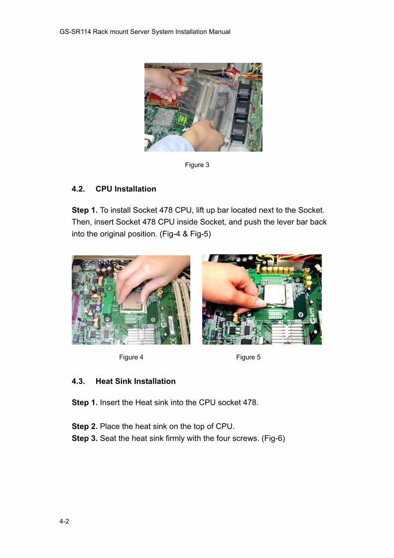
Figure 3
4.2. CPU Installation
Step 1. To install Socket 478 CPU, lift up bar located next to the Socket. Then, insert Socket 478 CPU inside Socket, and push the lever bar back into the original position. (Fig-4 & Fig-5)
Figure 4 Figure 5
4.3. Heat Sink Installation
Step 1. Insert the Heat sink into the CPU socket 478. Step 2. Place the heat sink on the top of CPU. Step 3. Seat the heat sink firmly with the four screws. (Fig-6)

GS-SR114 Rack mount Server System Installation Manual
4-3
Figure 6
4.4. Memory Installation
The motherboard contains three slanted DIMM (Dual Inline Memory Module) sockets. The systems BIOS will auto detect the size of the memory. To install memory, simply push the memory modules into the DIMM sockets. (Fig-7)
Figure 7
4.5. PCI Expansion Card Installation
GS SR114 series provide one PCI riser card with two slots, support 32bit/33MHz; one slot is for full-height PCI card; and another is for the dual LAN cards. To install the PCI expansion cards, please go through the following steps. Step 1. There are two screws holding the raiser bracket. First, remove the screw on the left of the bracket, then, remove another screws located at the rear of the server. (Fig-8).
GS-SR114 Rack mount Server System Installation Manual
4-4
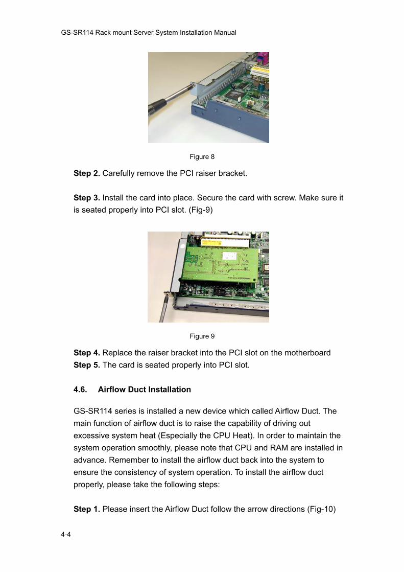
Figure 8
Step 2. Carefully remove the PCI raiser bracket. Step 3. Install the card into place. Secure the card with screw. Make sure it is seated properly into PCI slot. (Fig-9)
Figure 9
Step 4. Replace the raiser bracket into the PCI slot on the motherboard Step 5. The card is seated properly into PCI slot.
4.6. Airflow Duct Installation
GS-SR114 series is installed a new device which called Airflow Duct. The main function of airflow duct is to raise the capability of driving out excessive system heat (Especially the CPU Heat). In order to maintain the system operation smoothly, please note that CPU and RAM are installed in advance. Remember to install the airflow duct back into the system to ensure the consistency of system operation. To install the airflow duct properly, please take the following steps: Step 1. Please insert the Airflow Duct follow the arrow directions (Fig-10)

GS-SR114 Rack mount Server System Installation Manual
4-5
Figure 10
4.7. Reinstall Top Cover
When complete the installation of the entire essential components (from subsection 4.1 to 4.6), replace the transparent plastic air duct. This will secure the Airflow is inside the chassis. Failure to do so may cause CPU and Memory over heat. Replace the top cover, insuring that the thumbscrews are tightened. (Fig-11 & Fig-12)
Figure 11 Figure 12

GS-SR114 Rack mount Server System Installation Manual
4-6
4.8. Dock Handle Installation
Remove the dock handles from the package. Put two on each side of the chassis, secure with screws provided (Fig-13).
Figure 13
4.9. Hard Disk Drive Installation
Step 1. Then, remove the screw from the Hard Disk plate. (Fig-14)
Figure 14

GS-SR114 Rack mount Server System Installation Manual
4-7
Step 2. Carefully remove the Hard Disk plate follow the arrow direction. (Fig-15).
Figure 15
Step 3. Put Hard Disk Drive (Master mode) on to the Hard Disk plate and secure each hard disk drive with screws. (Fig-16)
Figure 16
Step 4. Re-install the Hard Disk plate with the Hard Drive into system and ensure it meets the IDE Hard Disk connectors. (Fig-17) Step 5. Secure each hard disk plate with screws. (Fig 18)
Figure 17 Figure 18
GS-SR114 Rack mount Server System Installation Manual
4-8
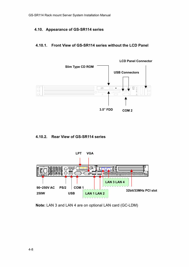
4.10. Appearance of GS-SR114 series
4.10.1. Front View of GS-SR114 series without the LCD Panel
4.10.2. Rear View of GS-SR114 series
Note: LAN 3 and LAN 4 are on optional LAN card (GC-LDM)
32bit/33MHz PCI slot
LAN 3 LAN 4
LAN 1 LAN 2
VGALPT
COM 1PS/2 USB
90~250V AC
250W
Slim Type CD ROM LCD Panel Connector
COM 23.5” FDD
USB Connectors
GS-SR114 Rack mount Server System Installation Manual
4-9
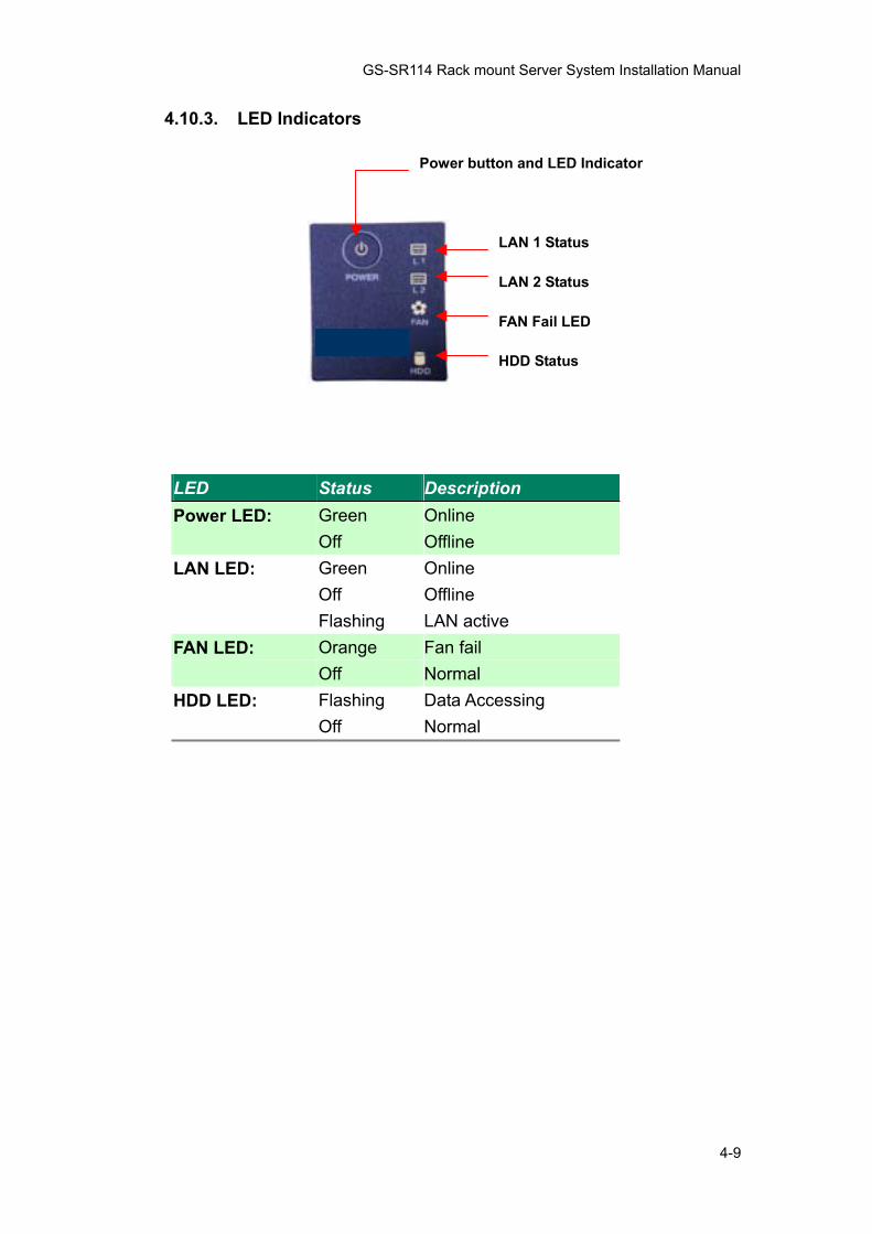
4.10.3. LED Indicators
LED Status Description Power LED: Green Online Off Offline LAN LED: Green Online Off Offline Flashing LAN active FAN LED: Orange Fan fail Off Normal HDD LED: Flashing Data Accessing Off Normal
Power button and LED Indicator
LAN 1 Status
LAN 2 Status
FAN Fail LED
HDD Status

GS-SR114 Rack mount Server System Installation Manual
4-10
4.11. Connector Icons
Suggested icons Description
Keyboard
VGA
Mouse
LAN
Parallel Port
Serial Port
USB

GS-SR114 Rack mount Server System Installation Manual
5-1
5. Using LCD Console (Optional) During startup, the liquid-crystal-display (LCD) screen on the front panel of the server displays status information about boot process itself. When setting up the SR-114, you can use LCD console to enter network configuration information for the SR-114.
5.1. Installing LCD Panel
Step 1. Please check the LCD panel kit is included in the component package, which contains LCD panel, locker and screws. (Fig-19) Step 2. Put the locker into the case. (Fig-20)
Figure 19 Figure 20
Step 3. Insert LCD panel cable into system connector. (Fig-21) Step 4. Secure LCD panel with two screws. (Fig-22)
Figure 21 Figure 22

GS-SR114 Rack mount Server System Installation Manual
5-2
5.2. LCD Panel Driver Installation
The installation procedures illustrated below indicating the installation
under Windows 2000 system. Step 1. To install driver for the LCD panel, double click “setup.exe” icon on the floppy disk. Note that after installing the driver, the front side COM2 port function will be disable automatically. Step 2. Installation Completed. Restart your computer.
5.3. Upgrading the Existing Driver
To upgrading the existing driver, please un-install the previous driver by following the procedures at 5.4 Un-installing the Existing Driver.
5.4. Un-installing the Existing Driver
To un-install LCD panel driver, go to Star > Programs > GBT LCD Service > Remove Gservice.exe. Then, Star > Programs > GBT LCD Service >Un-install shield. (Fig-23)
Figure 23
The driver is un-installed successfully.
GS-SR114 Rack mount Server System Installation Manual
5-3
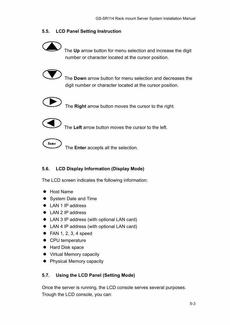
5.5. LCD Panel Setting Instruction
The Up arrow button for menu selection and increase the digit number or character located at the cursor position.
The Down arrow button for menu selection and decreases the digit number or character located at the cursor position.
The Right arrow button moves the cursor to the right.
The Left arrow button moves the cursor to the left.
The Enter accepts all the selection.
5.6. LCD Display Information (Display Mode)
The LCD screen indicates the following information: Host Name System Date and Time LAN 1 IP address LAN 2 IP address LAN 3 IP address (with optional LAN card) LAN 4 IP address (with optional LAN card) FAN 1, 2, 3, 4 speed CPU temperature Hard Disk space Virtual Memory capacity Physical Memory capacity
5.7. Using the LCD Panel (Setting Mode)
Once the server is running, the LCD console serves several purposes. Trough the LCD console, you can:

GS-SR114 Rack mount Server System Installation Manual
5-4
Input Password Configure the LAN 1 IP address, Netmask, Gateway, and DNS settings Configure the LAN 2 IP address, Netmask, Gateway, and DNS settings Configure the LAN 3 IP address, Netmask, Gateway, and DNS settings
(with optional LAN card) Configure the LAN 4 IP address, Netmask, Gateway, and DNS settings
(with optional LAN card) Welcome Message Setting Display time setting (Default 2 sec) Computer information menu: user can set the desired information
whether to be shown or not. System time setting Change Password Reboot System Power Down System Return to the main menu
5.8. Boot Sequence Selection
When the system is turned on, the LCD screen will display status information about the boot process itself. To make the Boot Sequence Selection: Step 1. The LCD screen displays: Boot from LAN? Press <Enter> Step 2. To boot form LAN, press the Enter button to select boot form LAN in 10 seconds. Or, not press any button, the system will follow the default setting of boot sequence from BIOS after 10 seconds.
5.9. Password Entering and Resetting
When user enter LCD console setting mode, user is required to enter password. Enter the default password “9999”.

GS-SR114 Rack mount Server System Installation Manual
5-5
For security consideration, please change the password after entering
the setting mode first time. Please well remember the changed password. If user forgets the changed password, un-install LCD Panel driver and re-install the driver again. 5.9.1. Password Entering Step 1. Press the Enter button, the LCD screen displays:
Input Password: 0**** Step 2. Use the ▲ button and the ▼ button to increase or decrease the digital number. Step 3. Use the ◄ button and the ►button to change cursor right or left. (The default password is “9999”) Step 4. Press the Enter button.
If user enters the incorrect password, the LCD screen will display the
message: “Password Error!” and returns to the display mode. 5.9.2. Password Setting Step 1. Press the Enter button and go through process 5.9.1 Password Entering Step 2. Use the ▲ button and the ▼ button to select “Change Password” and then press the Enter button. The LCD screen displays: New Password: 0*** Step 3. Use the ▲ button and the ▼ button to increase or decrease the desired digital number.

GS-SR114 Rack mount Server System Installation Manual
5-6
Step 4. Use the ◄ button and the ►button to change cursor right or left.
The new password is restrict with exact 4 digital numbers
Step 5. Press the Enter button. The LCD screen displays: “ Save change?” Step 6. Use the ▲ button and the ▼ button to select “Yes, Save!!” or “No, cancel” Step 7. By selecting “Yes, Save!!” The LCD screen displays: “Wait a moment!!” and return to setting mode. The password is changed successfully. Step 8. By selecting “No, Cancel!” the LCD screen will return to setting mode directly and the password is not changed.
5.10. Return to the Main Menu
When entering the setting mode successfully, user can use the▲ and the ▼button to select “Return??” and press the Enter button to return the display mode.
5.11. Configure LAN 1 (LAN 2) IP Address, Netmask, Gateway and DNS
Step 1. Press the Enter button and go through process 5.9.1 Step 2. Use the ▲ button and the ▼ button to select “ LAN 1(LAN 2) Setting? ” and press the Enter button. The LCD screen displays: “Use DHCP?” Step 3. Use the ▲ button and the ▼ button to select ‘Yes’ or ‘NO’
GS-SR114 Rack mount Server System Installation Manual
5-7
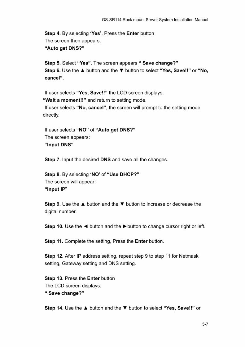
Step 4. By selecting ‘Yes’, Press the Enter button The screen then appears: “Auto get DNS?” Step 5. Select “Yes”. The screen appears “ Save change?” Step 6. Use the ▲ button and the ▼ button to select “Yes, Save!!” or “No, cancel”. If user selects “Yes, Save!!” the LCD screen displays:
“Wait a moment!!” and return to setting mode. If user selects “No, cancel”, the screen will prompt to the setting mode
directly. If user selects “NO” of “Auto get DNS?” The screen appears: “Input DNS” Step 7. Input the desired DNS and save all the changes. Step 8. By selecting ‘NO’ of “Use DHCP?” The screen will appear: “Input IP” Step 9. Use the ▲ button and the ▼ button to increase or decrease the digital number. Step 10. Use the ◄ button and the ►button to change cursor right or left. Step 11. Complete the setting, Press the Enter button. Step 12. After IP address setting, repeat step 9 to step 11 for Netmask setting, Gateway setting and DNS setting. Step 13. Press the Enter button The LCD screen displays: “ Save change?” Step 14. Use the ▲ button and the ▼ button to select “Yes, Save!!” or

GS-SR114 Rack mount Server System Installation Manual
5-8
“No, cancel”. If user selects “Yes, Save!!” the LCD screen displays: “Wait a moment!!” and return to setting mode. The IP address and Netmask is changed successfully. If user selects “No, Cancel!” the LCD screen will return to setting mode directly and all the required settings will not be changed.
5.12. Welcome Message Setting
Step 1. Press the Enter button and go through process 5.9.1 Step 2. Use the ▲ button and the ▼ button to select “ Welcome Message Setting? ” and press the Enter button Step 3. Use the ▲ button and the ▼ button to select character. Step 4. Use the ◄ button and the ►button to change cursor right or left. Step 5. Press the Enter button The LCD screen displays: “ Save change?” Step 6. Use the ▲ button and the ▼ button to select “Yes, Save!!” or “No, cancel”. If user selects “Yes, Save!!” The LCD screen displays: “Wait a moment!!” and return to setting mode. The Welcome Message is successfully changed. If user selects “No, Cancel!” the LCD screen will return to setting mode directly and all the required settings will not be changed.

GS-SR114 Rack mount Server System Installation Manual
5-9
5.13. Display Time Setting
Step 1. Press the Enter button and go through process 5.9.1 Step 2. Use the ▲ button and the ▼ button to select “ Display Time Setting? ” and press the Enter button Step 3. Use the ▲ button and the ▼ button to increase or decrease the digital number. Step 4. Use the ◄ button and the ►button to change cursor right or left. Step 5. Press the Enter button The LCD screen displays: “ Save change?” Step 6. Use the ▲ button and the ▼ button to select “Yes, Save!!” or “No, cancel”. If user selects “Yes, Save!!” The LCD screen displays: “Wait a moment!!” and return to setting mode. The Display Time is successfully changed. If user selects “No, Cancel!” the LCD screen will return to setting mode directly and all the required settings will not be changed.
5.14. Computer Information Menu Setting
The computer information menu setting is to a function for user to select which system information that desired to be displayed on the LCD screen. It contains information of Time, IP, Hardware Monitor, Disk Info and Memory Info. To start up Computer Information Setting: Step 1. Press the Enter button and go through process 5.9.1 Step 2. Use the ▲ button and the ▼ button to select “Computer Info Menu? ” and press the Enter button

GS-SR114 Rack mount Server System Installation Manual
5-10
The LCD screen displays Show this Info? Time * Step 3. Press Enter to make selection. Step 4. If user wants to select the certain item, press the Enter button. Then, the right hand side of the selected item on the screen will appear a “*” mark. Step 5. If user wants to cancel the certain item selection, press the Enter button again and the “*” mark will be disappeared. Step 6. Use the ▲ button and the ▼ button to select “OK and Return ” and press the Enter button to return the display mode.
5.15. System Time Setting
Step 1. Press the Enter button and go through process 5.9.1 Step 2. Use the ▲ button and the ▼ button to select “System Time Setting ” and press the Enter button Step 3. Use the ▲ button and the ▼ button to increase or decrease the digital number. Step 4. Use the ◄ button and the ►button to change cursor right or left. Step 5. Press the Enter button The LCD screen displays: “ Save change?” Step 6. Use the ▲ button and the ▼ button to select “Yes, Save!!” or “No, cancel”. If user selects “Yes, Save!!” The LCD screen displays: “Wait a moment!!” and return to setting mode. The System Time is successfully changed.

GS-SR114 Rack mount Server System Installation Manual
5-11
If user selects “No, Cancel!” the LCD screen will return to setting mode directly and all the required settings will not be changed.
5.16. Rebooting (System Rebooting)
Rebooting the server can sometimes cure problems with certain services and is required to recover from RAID failure. To reboot your server: Step 1. Press the Enter button and go through process 5.9.1 Step 2. Use the ▲ button and the ▼ button to select “Reboot ” and press the Enter button Step 3. The LCD screen displays “Are you sure?” Step 4. Use the ▲ button and the ▼ button to select ‘Yes!!’ or ‘No!’. If user selects “Yes!!” the system will reboot automatically. If user selected “No!” the LCD screen will return to display mode directly.
5.17. Powering Down
To prevent the potential loss of data, it is important to follow the proper
power-down procedures before turning off the server. Step 1. Press the Enter button and go through process 5.9.1 Step 2. Use the ▲ button and the ▼ button to select “Power Off ” and press the Enter button Step 3. The LCD screen displays “Are you sure?” Step 4. Use the ▲ button and the ▼ button to select ‘Yes!!’ or ‘No!’. If user selects “Yes!!” the Server shuts down the services currently running

GS-SR114 Rack mount Server System Installation Manual
5-12
and powers down. If user selects “No, Cancel!” the LCD screen will return to setting mode directly and all the required settings will not be changed.
5.18. Appearance of LCD Panel
LCD Panel Buttons and Indicators Description
Power On/Off
Button
LCD Panel
Operating Buttons
HDD
Status
Fan Fail LED LAN 1 Status
LAN 2 Status
Add LAN 3 / 4
Status LED