grundfos cr service manual - microsoft … cr service manual contents dismantling procedures page 2...
TRANSCRIPT

GRUNDFOS
CR SERVICE MANUAL
CONTENTSDismantling Procedures ................................................Page 2 When Should A Part Be Replaced ? ............................................ Page 10
Reassembly Procedures .............................................. Page 11 Setting The Coupling Height ....................................................... Page 18 Order of Stage Assembly: CR-H, CRN-H .................................... Page 20 Order of Stage Assembly: CR-H, CRN-H Low NPSH 10 ......... Page 21 Order of Stage Assembly: CR-H, CRN-H 15/20 ....................... Page 22 Order of Stage Assembly: CR-H, CRN-H Low NPSH 15/20 .. Page 23
CR-H, CRN-H 10•15•20Dismantling &
Reassembly
PositionNumber 7a Coupling Guard Screw ............................ 1.5 ft.-lbs./2 Nm
9 Coupling Hex Screw 5 mm M6 Screw ...................................10 ft.-lbs./13 Nm 6 mm M8 Screw ...................................23 ft.-lbs./31 Nm 8 mm M10 Screw ................................46 ft.-lbs./62 Nm
26b Strap Bolt 13 mm M8 x 25 mm ...........................11 ft.-lbs./15 Nm
28 Motor Bolt 9/16" UNC 3/8" Bolt ...........................10 ft.-lbs./13 Nm 3/4" UNC 1/2" Bolt..............................23 ft.-lbs./31 Nm
28g Allen Screw for Foot/Base.....................15 ft.-lbs./20 Nm 35 Allen Screw for Discharge Flange .......15 ft.-lbs./20 Nm
36 Staybolt Nut CR-H ........................................................59 ft.-lbs./80 Nm CRN-H .................................................. 74 ft.-lbs./100 Nm
56 c/e Allen Screw for Sleeve Flange ..............55 ft.-lbs./75 Nm
67 Shaft Lock Nut ...................................... 16.3 ft.-lbs./22 Nm
105 (a,b) Shaft Seal 41 mm Nut ............................................26 ft.-lbs./35 Nm 113 2.5 mm Set Screw ................................ 2 ft.-lbs./2.5 Nm
TORQUES

2
Remove the 5, 6 or 8 mm Hex Head Coupling Bolts (Pos. 9) from the Coupling Halves (Pos. 10a).
Dismantling Procedures CR-H, CRN-H 10•15•20
2
To free/remove remaining Coupling Half. Strike Coupling Half with a rubber mallet on upper edge. Remove shaft pin (Pos. 10).
NOTE: If you have multiple pumps, do not interchange coupling components...they are a matched set.
4
Remove Coupling Halves. Insert a slotted Screwdriver in Coupling gap and twist to free Coupling Half.
3
Depending on motor stool length, the
motor may need to be removed to
change out the shaft seal. For those
units, follow step 6. For the longer
motor stool, skip to step 7.
Units where you're changing out the
stack or dismantling the pump, step 6
will also have to be followed.
5
These instructions cover the complete
dismantling and repair of the pump
after the pump has been isolated from
the system. Before removing the pump
from the system, make sure all valves
are closed. Relieve any built up pressure
by opening the vent plug screw. The
power source should be turned off and
locked out before starting any work.
Removal of field wiring to the motor
wires may be required. Color coding
or numbering the wires will aid in
reinstallation.
Using a slotted Screwdriver or TORX® tip T20, remove Coupling Guard Screws (Pos. 7a). Then, remove the Coupling Guards (Pos. 7).
1
If only replacing the shaft seal, follow steps 1 - 7.
6
To remove the motor:Loosen and remove the 9/16" Head UNC 3/8" or 3/4" Head UNC 1/2" Motor Bolts (Pos. 28). Loosen the Slide Rail (Pos. 90d) connecting the motor to the Base (Pos. 90), then slide the motor backward on the base. If sliding provisions are not available on the base, then use a lifting device to lift and remove the motor assembly.

Loosen (but do not remove) the four 24 mm Staybolt Nuts (Pos. 36). These will be removed in step 12.
Remove the cartridge Shaft Seal (Pos. 105) by:
· Loosening the three 2.5 mm Shaft Seal Securing Allen Screws (Pos. 113) approximately 1/2 to 1 turn.
· Using the Specialty Tubular Box Spanner (00SV2107), a 41 mm ring spanner (00SV2101), or a deep socket, fully unscrew the Shaft Seal from the Motor Stool (Pos. 2) or Pump Head
(Pos. 77) on N models.
· Sliding the Shaft Seal up and off the Shaft (Pos. 51).
For Shaft Seal replacement only, go to Reassembly, steps 24 & 25. For full dismantling, continue to step 8.
7
9
Loosen and remove all the Sleeve Flange Nuts (Pos. 56e), Allen Screws (Pos. 56c), and Washers (Pos. 56d) from the Sleeve Flange (Pos. 55b).
10
Remove the plastic plugs from the threaded jacking holes. Next, use two of the sleeve flange allen screws and place into the threaded holes of the sleeve flange. Tightened diagonally, this will force the cartridge assembly (Pos. 80a) away from the Suction/Discharge Base (Pos. 6). Warning: Do not allow the cartridge assembly to fall.
To remove the Cartridge Assembly (Pos. 80a) from the Suction/Discharge Base (Pos. 6), grab the two top staybolts and slide outward (some rocking movement may be required). Warning: Cartridge assemblies are heavy – a lifting device may be required.
11
12
Move the cartridge assembly to a workbench. Then, finish removing the Staybolt Nuts (Pos. 36), Washers (Pos. 66a), and Support Plate (Pos. 90c). If needed, remove Coupling Guard Screws and Guard.
Remove the Motor Stool (Pos. 2) and Pump Head (Pos. 77) on N models. (Light upward blows with a rubber mallet may be required.)• If the pump is a standard unit, skip to Dismantling, step 28.• For Cool -Top® type/equipped pumps, see Dismantling, steps 14 to 18.• Pumps built with a Back-to-Back Seal, see Dismantling, steps 19 to 22.• Pumps built with Tandem/Quench Seal, see Dismantling, steps 23 to 27.
13
Dismantling Procedures CR-H, CRN-H 10•15•20
Continued...
3
8
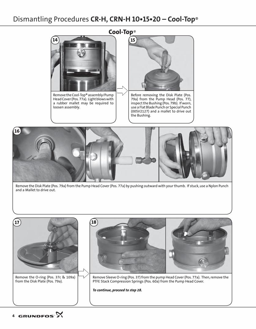
Dismantling Procedures CR-H, CRN-H 10•15•20 – Cool-Top®
Remove the Disk Plate (Pos. 79a) from the Pump Head Cover (Pos. 77a) by pushing outward with your thumb. If stuck, use a Nylon Punch and a Mallet to drive out.
Remove the Cool-Top® assembly/Pump Head Cover (Pos. 77a). Light blows with a rubber mallet may be required to loosen assembly.
Before removing the Disk Plate (Pos. 79a) from the Pump Head (Pos. 77), inspect the Bushing (Pos. 79b). If worn, use a Flat Blade Punch or Special Punch (00SV2127) and a mallet to drive out the Bushing.
Cool-Top®
16
Remove the O-ring (Pos. 37c & 109a) from the Disk Plate (Pos. 79a).
17
4
14 15
Remove Sleeve O-ring (Pos. 37) from the pump Head Cover (Pos. 77a). Then, remove the PTFE Stack Compression Springs (Pos. 60a) from the Pump Head Cover.
To continue, proceed to step 28.
18
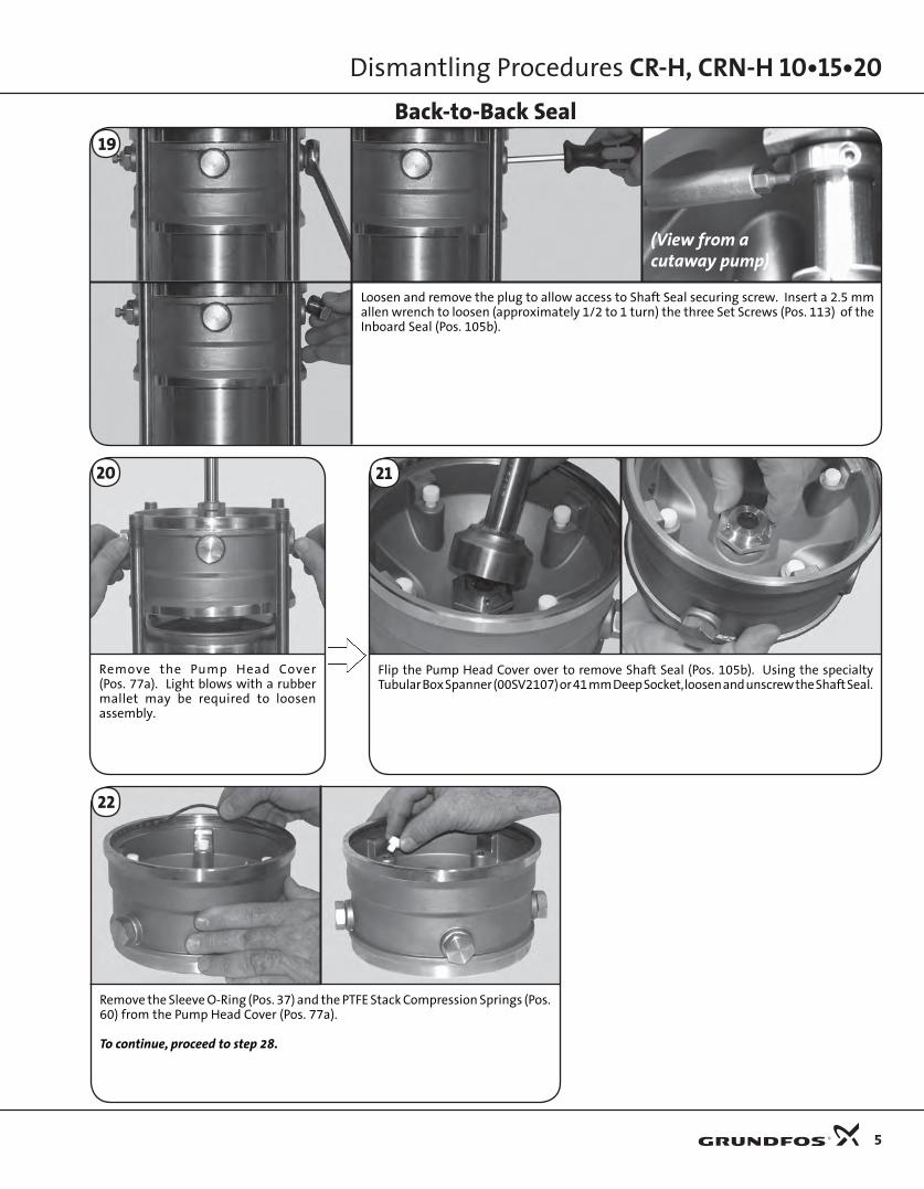
Dismantling Procedures CR-H, CRN-H 10•15•20
Loosen and remove the plug to allow access to Shaft Seal securing screw. Insert a 2.5 mm allen wrench to loosen (approximately 1/2 to 1 turn) the three Set Screws (Pos. 113) of the Inboard Seal (Pos. 105b).
Back-to-Back Seal
Remove the Sleeve O-Ring (Pos. 37) and the PTFE Stack Compression Springs (Pos. 60) from the Pump Head Cover (Pos. 77a).
To continue, proceed to step 28.
Flip the Pump Head Cover over to remove Shaft Seal (Pos. 105b). Using the specialty Tubular Box Spanner (00SV2107) or 41 mm Deep Socket, loosen and unscrew the Shaft Seal.
19
Remove the Pump Head Cover (Pos. 77a). Light blows with a rubber mallet may be required to loosen assembly.
20 21
22
(View from a cutaway pump)
5

Use specialty Tubular Box Spanner (00SV2107), a 41 mm Deep Socket, or an Open Ring Spanner to loosen.
Finish removal of Shaft Seal (Pos. 105b) from Pump Head Cover (Pos. 77a). Flip the Pump Head Cover over and go to step 27.
24
26
23
Loosen (approximately 1/2 to 1 turn) the three 2.5 mm Set Screws (Pos. 113) of the Inboard Seal (Pos. 105b).
Tandem Seal
Dismantling Procedures CR-H, CRN-H 10•15•20
Remove the Pump Head Cover (Pos. 77a). Light blows with a rubber mallet may be required to loosen assembly.
25
Remove the Sleeve O-Ring (Pos. 37) and the PTFE Stack Compression Springs (Pos. 60) from the Pump Head Cover (Pos. 77a).
27
To continue, proceed to step 28.
6

Move the shaft into a hole of the shaft holder through which it can pass freely. Screw the Punch for Dismantling Shaft (00SV0234) onto the threaded section of shaft. Using a hammer, drive punch down past the hub of the first impeller. Noting chart instructions in step 35, remove each impeller (Pos. 49a) and Chamber with bearing (Pos. 4a) and Chamber (Pos. 4).
Repeat these steps until you get down to the last impeller. At that time, gently knock the punch down through the hub area, make sure to catch the shaft as it falls free. Go to step 36.
Place the Holder for Shaft (00SV0040) in a vise. With the shaft pin inserted into the shaft, place the impeller stack into the shaft holder. Tighten vise. Using a 13 mm wrench, remove the Chamber Stack Strap Bolt (Pos. 26b), Washer (Pos. 26c), and Strap (Pos. 26a).
Lift the Impeller (Pos. 49a) off the shaft. If it comes off freely, proceed to step 34. If it is stuck and cannot be removed by hand, proceed to step 33.
29
32
33
Remove the
suction inlet
connector
(Pos. 44).
NOTE: This
may come
apart in two
pieces
(Pos. 44a &
44b).
30
Remove the Chamber with bearing (Pos. 4a) or Chamber (Pos. 4). If it is stuck to the rest of the stack, pry it loose by inserting a screwdriver between the chambers.
34
Using a 13 mm wrench, remove the Shaft Lock Nut (Pos. 67), Lock Washer (Pos. 66) and Splined Spacer (Pos. 64c).
31
Grab the shaft and lift Impeller Stack (Pos. 80) out of the pump. If it's stuck, a light blow with a rubber mallet may be needed to jolt the stack free. Go to the Reassembly section, step 12, for stack replacement instructions. If you need to disassemble the whole pump, proceed to steps 29-43.
28
Dismantling Procedures CR-H, CRN-H 10•15•20
7
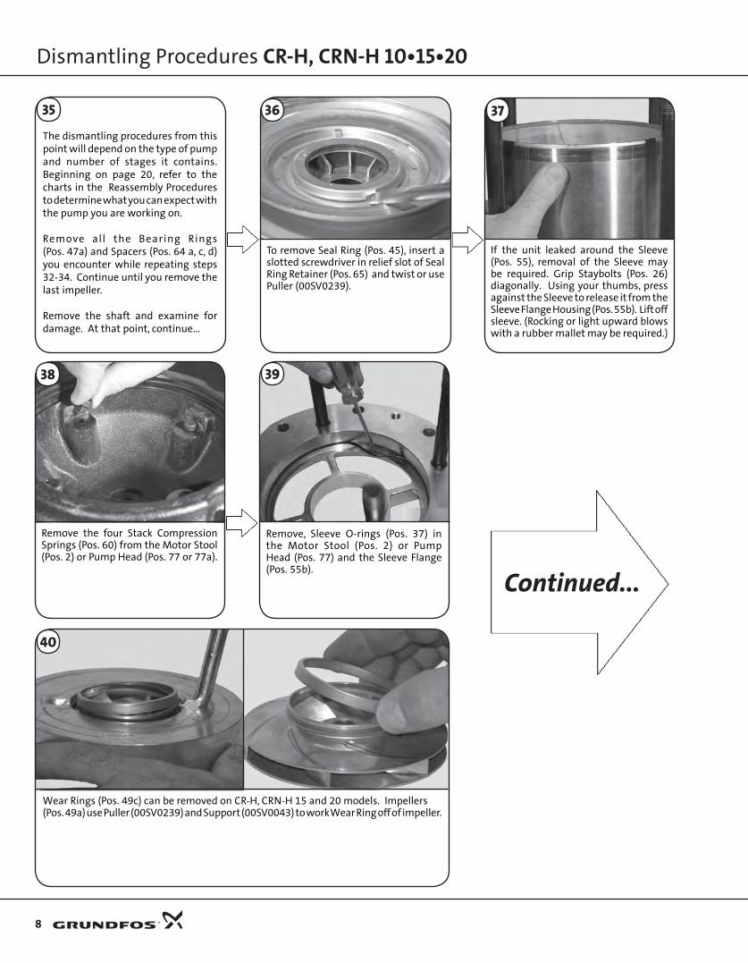
The dismantling procedures from this point will depend on the type of pump and number of stages it contains. Beginning on page 20, refer to the charts in the Reassembly Procedures to determine what you can expect with the pump you are working on.
Remove all the Bearing Rings(Pos. 47a) and Spacers (Pos. 64 a, c, d) you encounter while repeating steps 32-34. Continue until you remove the last impeller.
Remove the shaft and examine for damage. At that point, continue...
To remove Seal Ring (Pos. 45), insert a slotted screwdriver in relief slot of Seal Ring Retainer (Pos. 65) and twist or use Puller (00SV0239).
36
Remove the four Stack Compression Springs (Pos. 60) from the Motor Stool (Pos. 2) or Pump Head (Pos. 77 or 77a).
38
Remove, Sleeve O-rings (Pos. 37) in the Motor Stool (Pos. 2) or Pump Head (Pos. 77) and the Sleeve Flange (Pos. 55b).
39
If the unit leaked around the Sleeve (Pos. 55), removal of the Sleeve may be required. Grip Staybolts (Pos. 26) diagonally. Using your thumbs, press against the Sleeve to release it from the Sleeve Flange Housing (Pos. 55b). Lift off sleeve. (Rocking or light upward blows with a rubber mallet may be required.)
37
Dismantling Procedures CR-H, CRN-H 10•15•20
Wear Rings (Pos. 49c) can be removed on CR-H, CRN-H 15 and 20 models. Impellers (Pos. 49a) use Puller (00SV0239) and Support (00SV0043) to work Wear Ring off of impeller.
40
Continued...
8
35

Dismantling Procedures CR-H, CRN-H 10•15•20
Remove the Flange Allen Screws (Pos. 35).
Push the Flange Ring (Pos. 201[a]) down, use a screwdriver to remove the Retaining Ring (Pos. 203[a]), then remove the flange ring.
If the Discharge Adaptor Flange (12a) has leaked, the O-ring may need replacment. To remove, follow the next steps after removing the system discharge piping.
41 42
Remove the O-ring (Pos. 39b).
43
9
THE PUMP ISNOW COMPLETELY
DISASSEMBLED.
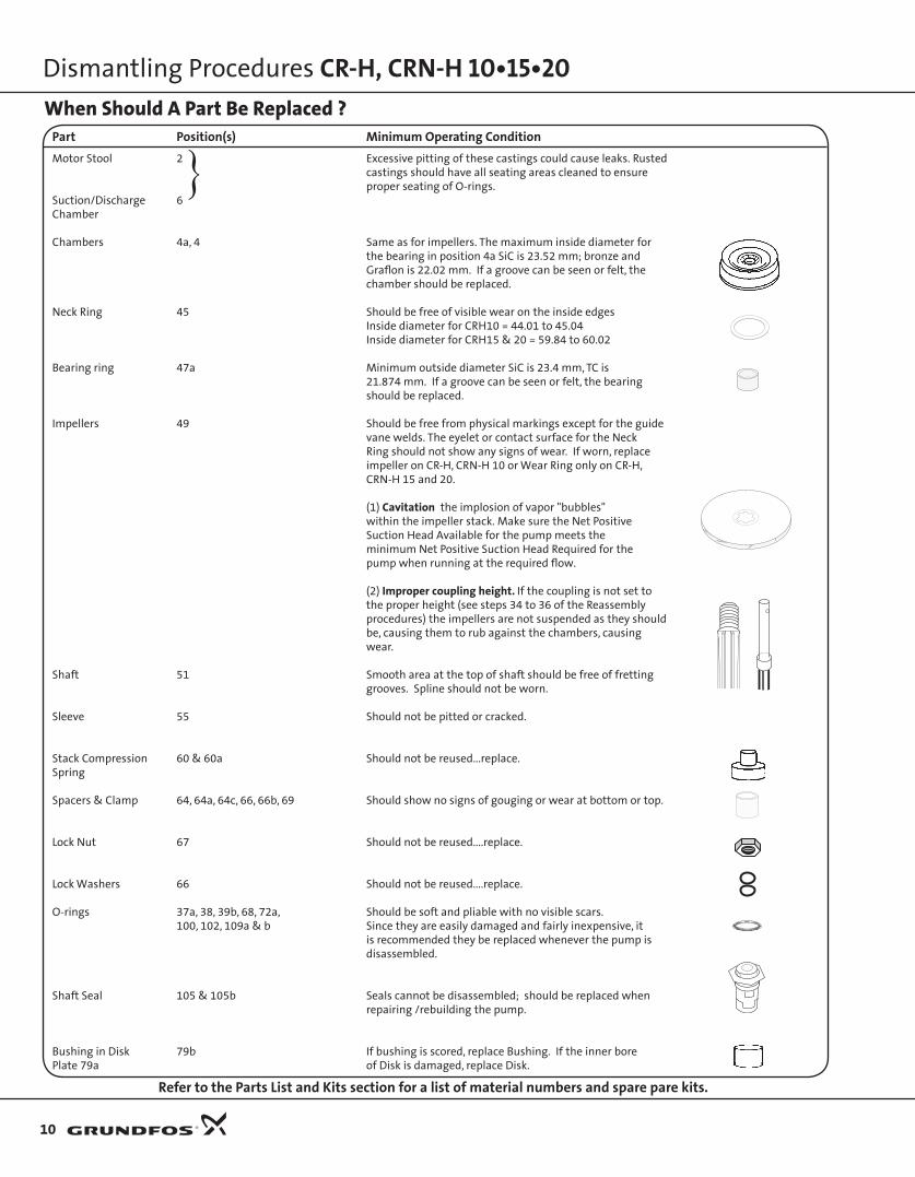
When Should A Part Be Replaced ?Part Position(s) Minimum Operating ConditionMotor Stool 2 Excessive pitting of these castings could cause leaks. Rusted
castings should have all seating areas cleaned to ensure proper seating of O-rings.
Suction/Discharge 6Chamber
Chambers 4a, 4 Same as for impellers. The maximum inside diameter for the bearing in position 4a SiC is 23.52 mm; bronze and
Graflon is 22.02 mm. If a groove can be seen or felt, the chamber should be replaced.
Neck Ring 45 Should be free of visible wear on the inside edges Inside diameter for CRH10 = 44.01 to 45.04 Inside diameter for CRH15 & 20 = 59.84 to 60.02
Bearing ring 47a Minimum outside diameter SiC is 23.4 mm, TC is 21.874 mm. If a groove can be seen or felt, the bearing
should be replaced.
Impellers 49 Should be free from physical markings except for the guide vane welds. The eyelet or contact surface for the Neck Ring should not show any signs of wear. If worn, replace impeller on CR-H, CRN-H 10 or Wear Ring only on CR-H,
CRN-H 15 and 20.
(1) Cavitation the implosion of vapor "bubbles" within the impeller stack. Make sure the Net Positive Suction Head Available for the pump meets the minimum Net Positive Suction Head Required for the pump when running at the required flow.
(2) Improper coupling height. If the coupling is not set to the proper height (see steps 34 to 36 of the Reassembly procedures) the impellers are not suspended as they should be, causing them to rub against the chambers, causing wear.
Shaft 51 Smooth area at the top of shaft should be free of fretting grooves. Spline should not be worn.
Sleeve 55 Should not be pitted or cracked.
Stack Compression 60 & 60a Should not be reused...replace.Spring
Spacers & Clamp 64, 64a, 64c, 66, 66b, 69 Should show no signs of gouging or wear at bottom or top.
Lock Nut 67 Should not be reused....replace.
Lock Washers 66 Should not be reused....replace.
O-rings 37a, 38, 39b, 68, 72a, Should be soft and pliable with no visible scars. 100, 102, 109a & b Since they are easily damaged and fairly inexpensive, it
is recommended they be replaced whenever the pump is disassembled.
Shaft Seal 105 & 105b Seals cannot be disassembled; should be replaced when repairing /rebuilding the pump.
Bushing in Disk 79b If bushing is scored, replace Bushing. If the inner borePlate 79a of Disk is damaged, replace Disk.
Refer to the Parts List and Kits section for a list of material numbers and spare pare kits.
10
Dismantling Procedures CR-H, CRN-H 10•15•20
}
Reassembly Procedures CR-H, CRN-H 10•15•20
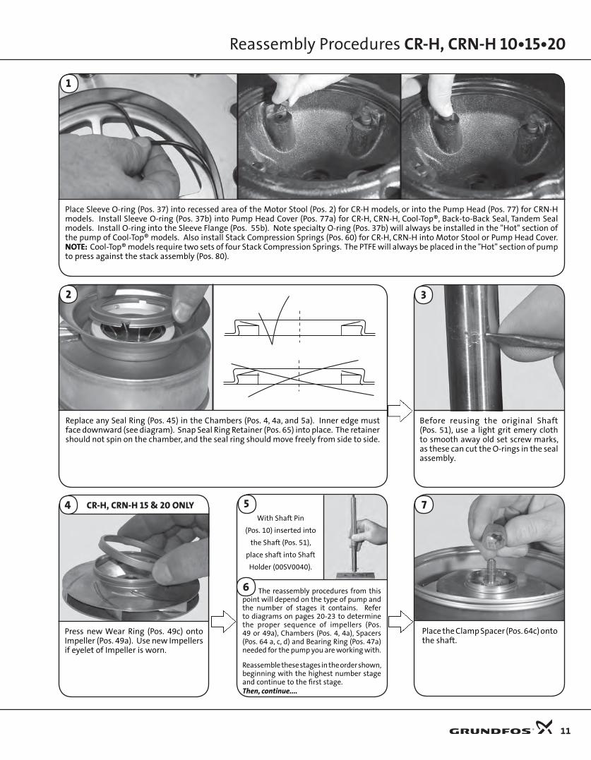
Place Sleeve O-ring (Pos. 37) into recessed area of the Motor Stool (Pos. 2) for CR-H models, or into the Pump Head (Pos. 77) for CRN-H models. Install Sleeve O-ring (Pos. 37b) into Pump Head Cover (Pos. 77a) for CR-H, CRN-H, Cool-Top®, Back-to-Back Seal, Tandem Seal models. Install O-ring into the Sleeve Flange (Pos. 55b). Note specialty O-ring (Pos. 37b) will always be installed in the "Hot" section of the pump of Cool-Top® models. Also install Stack Compression Springs (Pos. 60) for CR-H, CRN-H into Motor Stool or Pump Head Cover. NOTE: Cool-Top® models require two sets of four Stack Compression Springs. The PTFE will always be placed in the "Hot" section of pump to press against the stack assembly (Pos. 80).
1
Replace any Seal Ring (Pos. 45) in the Chambers (Pos. 4, 4a, and 5a). Inner edge must face downward (see diagram). Snap Seal Ring Retainer (Pos. 65) into place. The retainer should not spin on the chamber, and the seal ring should move freely from side to side.
The reassembly procedures from this point will depend on the type of pump and the number of stages it contains. Refer to diagrams on pages 20-23 to determine the proper sequence of impellers (Pos. 49 or 49a), Chambers (Pos. 4, 4a), Spacers (Pos. 64 a, c, d) and Bearing Ring (Pos. 47a) needed for the pump you are working with.
Reassemble these stages in the order shown, beginning with the highest number stage and continue to the first stage.Then, continue....
2
Place the Clamp Spacer (Pos. 64c) onto the shaft.
7
Before reusing the original Shaft (Pos. 51), use a light grit emery cloth to smooth away old set screw marks, as these can cut the O-rings in the seal assembly.
3
11
Press new Wear Ring (Pos. 49c) onto Impeller (Pos. 49a). Use new Impellers if eyelet of Impeller is worn.
With Shaft Pin
(Pos. 10) inserted into
the Shaft (Pos. 51),
place shaft into Shaft
Holder (00SV0040).
4 CR-H, CRN-H 15 & 20 ONLY
6
5

12
Reassembly Procedures CR-H, CRN-H 10•15•20
Place Suction Inlet Connector (Pos. 44a & b) onto Stack. Insert Straps (Pos. 26a) into slot in Top Chamber (Pos. 3). Place Washers (Pos. 26c) and Strap Bolt (Pos. 26b) on/into the Straps using a 13 mm Socket (00SV0091), and Torque Wrench (00SV0292), with Ratchet (00SV0295) to Torque Bolt to 11 ft.-lbs./15 Nm. Bolt should be lubricated with Gardolube.
10
Lubricate the threaded end of the shaft with Gardolube (00SV9995). Thread the Lock Nut (Pos. 67) onto the shaft and torque to 16.3 ft.-lbs./22 Nm. Use 13 mm Socket (00SV0091), Ratchet (00SV0295), and Torque Wrench, (00SV0269).
9
The Lock Washers (Pos. 66) come as a set. If they become separated, it is important the washers are repositioned correctly as noted in the diagram. The tabs should interlock while the serrated edges both point outward. Place the washers onto the shaft.
8
Lower new Stack Kit (Pos. 80) into the Sleeve
Flange. Make sure it seats fully into the
machined recess. (Chamber Straps must be
located as pictured, centered between the
staybolts.)
12
Lubricate the O-ring with Dow Corn-ing 111 or Rocol (Material Number 00RM2924) or spray soapy water on the Sleeve O-rings (Pos. 37). Then lower and press Sleeve (Pos. 55) firmly into place. This may require gentle taps with a rubber mallet. Vent sticker should line up with flat surface of sleeve flange.
11
Strap location viewed from the bottom
> Standard CR-H, CRN-H models skip to step 22
> Cool-Top® models skip to step 13
> Back-to-Back Seal models skip to step 17
> Tandem Seal models skip to step 19
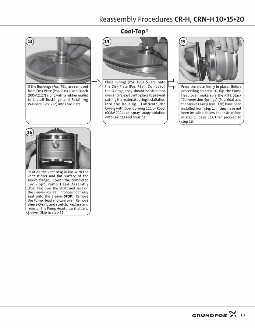
Place O-rings (Pos. 109a & 37c) onto the Disk Plate (Pos. 79a). Do not roll the O-rings; they should be stretched over and released into place to prevent cutting the material during installation into the housing. Lubricate the O-ring with Dow Corning 111 or Rocol (00RM2924) or spray soapy solution onto O-rings and housing.
Cool-Top®
Reassembly Procedures CR-H, CRN-H 10•15•20
13
If the Bushings (Pos. 79b) are removed from Disk Plate (Pos. 79a), use a Punch (00SV2127) along with a rubber mallet to install Bushings and Retaining Washers (Pos. 79c) into Disc Plate.
13
Press the plate firmly in place. Before proceeding to step 16, flip the Pump Head over; make sure the PTFE Stack "Compression Springs" (Pos. 60a) and the Sleeve O-ring (Pos. 37b) have been installed from step 1. If they have not been installed, follow the instructions in step 1 (page 11), then proceed to step 16.
15
16
Position the vent plug in line with the vent sticker and flat surface of the sleeve flange. Lower the completed Cool-Top® Pump Head Assembly (Pos. 77a) over the Shaft and seat on the Sleeve (Pos. 55). If it does not freely seat onto the Sleeve, STOP. Remove the Pump Head and turn over. Remove sleeve O-ring and stretch. Replace and reinstall the Pump Head onto Shaft and Sleeve. Skip to step 22.
14
Back-to-Back Seal
14
Reassembly Procedures CR-H, CRN-H 10•15•20
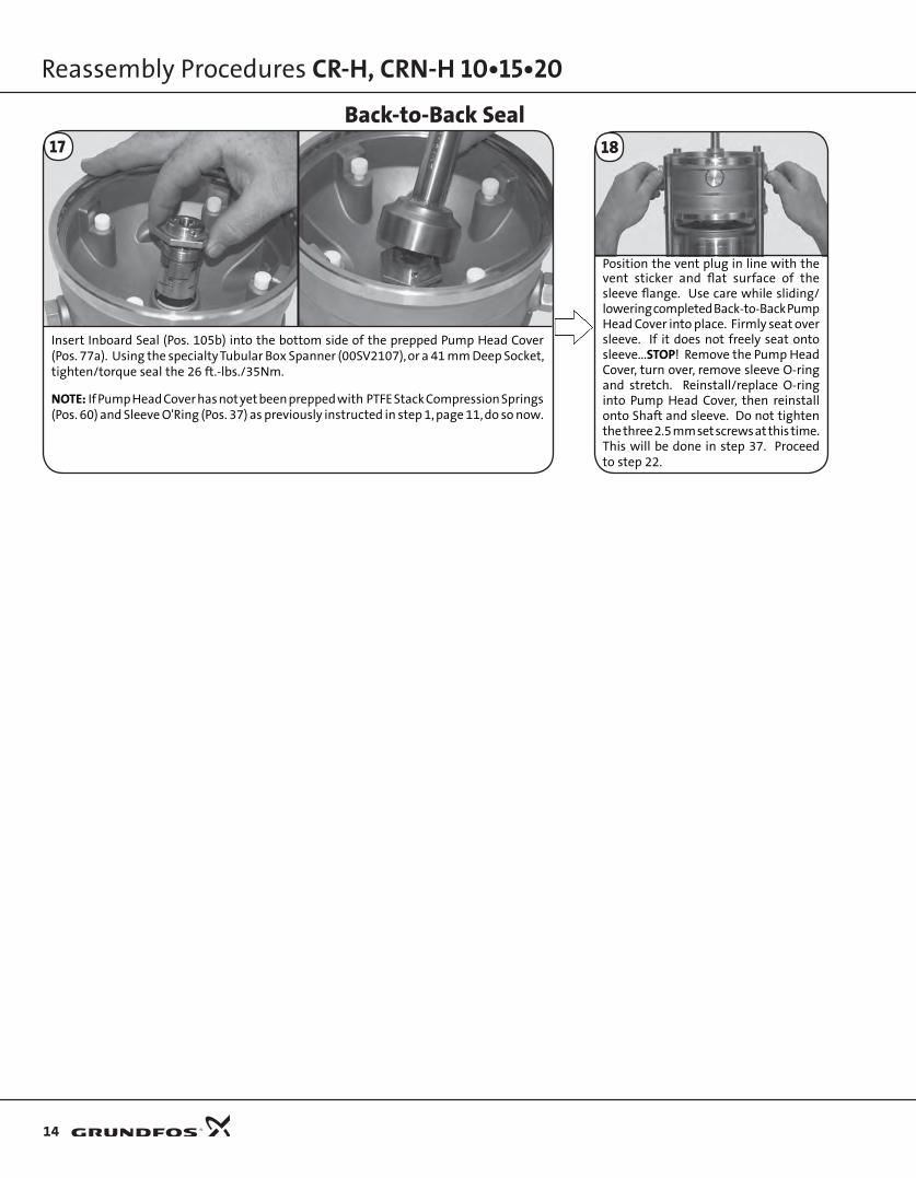
Position the vent plug in line with the vent sticker and flat surface of the sleeve flange. Use care while sliding/lowering completed Back-to-Back Pump Head Cover into place. Firmly seat over sleeve. If it does not freely seat onto sleeve...STOP! Remove the Pump Head Cover, turn over, remove sleeve O-ring and stretch. Reinstall/replace O-ring into Pump Head Cover, then reinstall onto Shaft and sleeve. Do not tighten the three 2.5 mm set screws at this time. This will be done in step 37. Proceed to step 22.
18
Insert Inboard Seal (Pos. 105b) into the bottom side of the prepped Pump Head Cover (Pos. 77a). Using the specialty Tubular Box Spanner (00SV2107), or a 41 mm Deep Socket, tighten/torque seal the 26 ft.-lbs./35Nm.
NOTE: If Pump Head Cover has not yet been prepped with PTFE Stack Compression Springs (Pos. 60) and Sleeve O'Ring (Pos. 37) as previously instructed in step 1, page 11, do so now.
17

Position the vent plug in line with the vent sticker and flat surface of the sleeve flange. Lower the completed Pump Head Assembly (Pos. 77a) over the shaft and seat on the Sleeve (Pos. 55). If it does not freely seat onto the sleeve...STOP. Remove the pump head and turn over. Remove sleeve O-ring and stretch. Replace and reinstall the pump head onto shaft and sleeve.
19
Slide the Inboard Seal (Pos. 105b) down the shaft and thread into the pump head. Use specialty Tubular Box Spanner (00SV2107), a 41 mm Open Ring Spanner (00SV2101) or a 41mm Deep Socket to torque the Inboard Seal to 26 ft.-lbs./35 Nm.
20
Tandem Seal
Reassembly Procedures CR-H, CRN-H 10•15•20
15
Push down on the coller area of the Seal, then lift Shaft to create a clearance of 123 mm from the top of the Shaft (Pos. 51) to the top of the Shaft Seal. Tighten the three 2.5 mm set screws to 2 ft.-lbs./2.5 Nm. Proceed to step 22.
21
An alternative to step 21 is when the special tool (00SV2078) and two 27.5 mm Spacers (96491537) are used with two Staybolt Nuts and Washers.
Place tool over Staybolts and seat against Pump Head Assembly (Pos. 77a). Slide 27 mm Spacers down Staybolts.
Place Washers and Nuts onto Staybolts and tighten diagonally to:
CR-H: 59 ft.-lbs./80 Nm CRN-H: 74 ft.-lbs./100 Nm
Push Shaft down, then tighten the three 2.5 mm Set Screws to 2 ft.-lbs./2.5 Nm. Remove Staybolt Nuts/Washers, 27 mm Spacers, and tool (00SV2078). Proceed to step 22.
Alternative to Step 21OR

Lubricate the O-ring with Dow Corning 111 or Rocol or spray soapy water on the Sleeve O-rings (Pos. 37) in the Motor Stool for CR-H or CRN-H Pump Head. Position the vent plug in line with the vent sticker and flat surface of the sleeve flange. Then lower and fully press in place.
22
Slide the cartridge Support Foot (Pos. 90c) over the staybolts opposite the vent plug. Place the Washers (Pos. 66a) over the Staybolts (Pos. 26). Then, lubricate with Gardolube (00SV9995), or Thread-Eze (96611372). Place the 24 mm Staybolt Nuts (Pos. 36) onto staybolts and loosely tighten. Do not torque at this time (torque at step 31).
23
16
Reassembly Procedures CR-H, CRN-H 10•15•20
If this was not done earlier, remove the old O-ring and clean the groove. Next, in four equally spaced areas, place a liberal amount of Dow Corning 111 or Rocol onto the ma-chined groove of the Suction/Discharge Base (Pos. 6). Fit the O-ring (Pos. 72a) into the groove, ensuring it is fully seated and does not move out of position.
27
Spray soapy water onto the Seal O-ring Seating Surface of the Pump Head and the Shaft (Pos. 51). (If reusing original Shaft, be sure to use Emery tool provided with Seal Kit to remove any burrs on the Shaft. Then, spray with soapy water.)
24
Pushing down on Shaft Seal collar (do not push down on Hex Nut), lower the new Shaft Seal (Pos. 105) over the Shaft. Use the specialty Tubular Spanner (00SV2107), a 41 mm Open Ring Spanner (00SV2101), or a 41 mm Deep Socket to tighten to 26 ft.-lbs./35 Nm.
Do not tighten the three set screws (Pos. 113) at this time, this will be done in step 33.
25
28
Place the first Coupling Guard with the support bracket. Install screws (pos. 7a) using a torque screwdriver with a slotted or Torx® tip T20, torque to 1.5 ft.-lbs./2 Nm. The cartridge assembly is now ready to take back to where the suction discharge volute is located.
26
Align the cartridge and slide it into the suction/discharge base, making sure that the O-ring from step 27 is still in place. Also, make sure the sleeve flange flat surface, venting label, and vent plug are facing upward.

29
Before installing the Screws (Pos. 56c), Washers (Pos. 56d), and Nuts (Pos. 56e) into the Sleeve Flange (Pos. 55b) ensure the flange is fully seated; there should not be any gap between the flange and the suction discharge base. If there is a gap, either the o-ring from step 27 has moved out of place and is pinched, or the flange is not properly engaged into the machined recess/register in the base (see the diagram above); repair before proceeding. If properly seated, apply Gardolube or Thread-eze to the screws, then torque diagonally to 55 ft.-lbs./75Nm.
Slide the motor assembly toward the Motor Stool and/or Spacer (Pos. 1), then install and tighten Motor Bolts (Pos. 28) diagonally to the proper torque.
17 ft.-lbs./23 Nm for UNC 3/8" bolts (9/16" Head), and 30 ft.-lbs./40 Nm for UNC 1/2” bolts (3/4" Head)
If the bolt holes do not align, slightly lifting and twisting the cartridge by the motor stool may be required to allow the motor stool register and holes to fully align/seat.
30
Place the Shaft Pin (Pos. 10) into the shaft (Pos. 51).
34
Reassembly Procedures CR-H, CRN-H 10•15•20
17
Torque the staybolt nuts diagonally to:
CR-H: 59 ft.-lbs./80 NmCRN-H: 74 ft.-lbs./100 Nm
31
Tighten the Slide Rail Screws (Pos. 90d) connecting the motor to the base.
32
Push the Shaft all the way down (for Tandem Seal models you must continue to apply downward force), then tighten the three 2.5 mm Shaft Seal Securing Allen Screws torque to 2 ft.-lbs./2.5 Nm.
33

Reassembly Procedures CR-H, CRN-H 10•15•20
Using a screwdriver, lift the Shaft upward. Insert two of the Spacer tools between Shaft Seal Collar and Hex Nut Outer Seal. Next, insert a 2.5 mm allen wrench through one of the lower vent port holes and torque the lower inboard seal securing screws to 2.0 ft.-lbs./2.5 Nm. Remove allen wrench and replace plugs (Pos. 23a) into the Pump Head Cover (Pos. 77a). Now remove one of the Spacer tools. From the Outer Seal, push the Shaft downward, ensuring the Seal Collar is resting on the tool. Then, tighten and torque the Coupling bolts to values in step 36.
Remove Spacer Tool, then spin the shaft by hand; proceed only if the shaft spins freely.
If the shaft does not spin freely: Stop and start over, inspecting the components for any cause of binding.
Place Shaft Seal Spacer tool(s) on to Coupling Guard(s).
39
Install the last Coupling Guard (Pos. 7) and the Screws (Pos. 7a). Using a Torque Screwdriver, with a slotted or a TORX® tip T20, torque to 1.5 ft.-lbs./2 Nm.
40
Spring tension from the seals may have already lifted the Shaft upward. If not, lift the Shaft upward. At this time insert the Shaft Seal Spacer tool. Remove the screwdriver. Ensure the Shaft has moved downward and shaft Seal Collar is resting on the tool. Tighten and torque the Coupling bolts to values in step 36.
Tandem Seal37 Back-to-Back Seal
18
Install the Coupling Halves (Pos. 10a). Apply Gardolube, Thread-eze, or spray a light machinery oil onto the Coupling Bolts (Pos. 9). Install loosely into the Couplings.
35
Using a screwdriver, lift the Shaft upward. Insert Shaft Seal Spacer tool between Shaft Seal Collar and Hex Nut. Remove the screwdriver and tighten and torque the Coupling Bolts.
Ensure the gap between the two Coupling Halves are even (see Diagram).
5 mm - M6 to 10 ft.-lbs./13 Nm 6 mm - M8 to 23 ft.-lbs./31 Nm 8 mm - M10 to 46 ft.-lbs/62 Nm
Standard Units and Cool Top®36
38
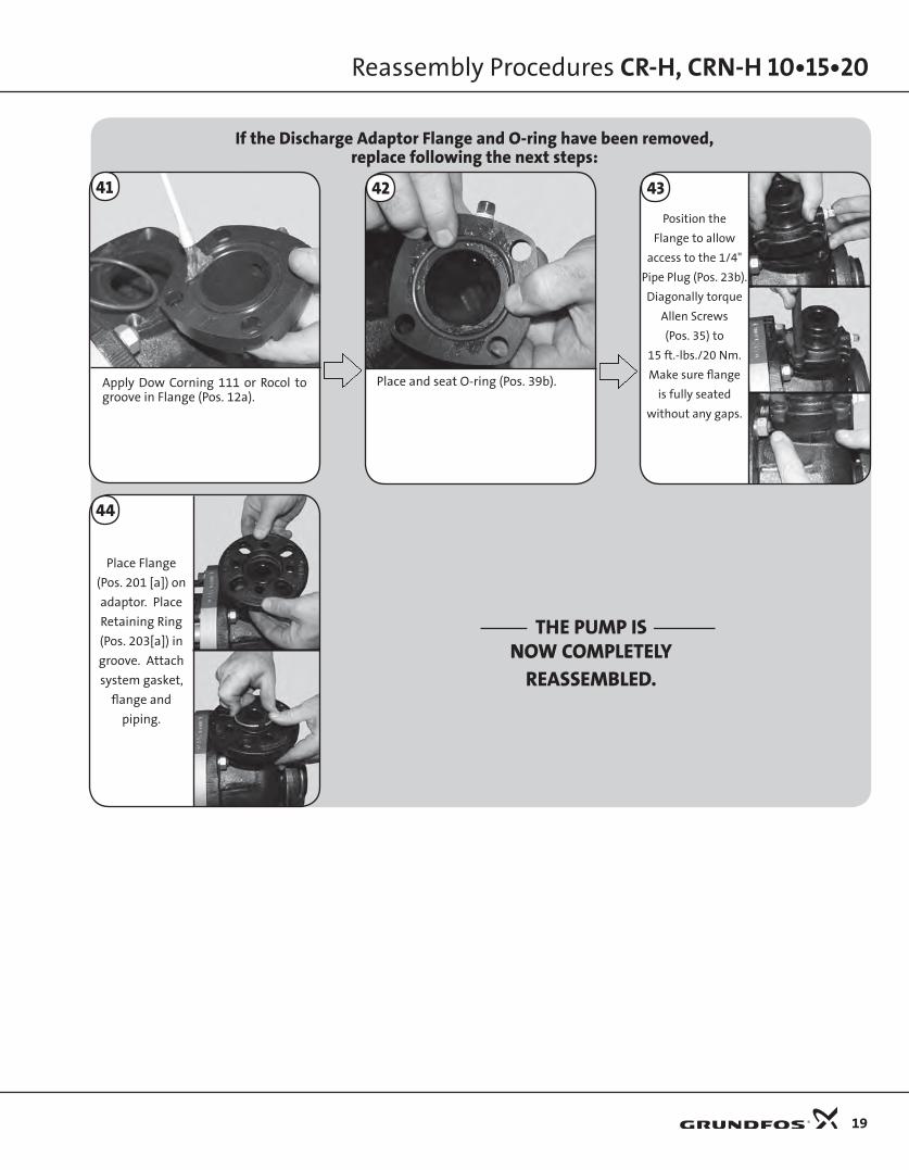
Place and seat O-ring (Pos. 39b).
If the Discharge Adaptor Flange and O-ring have been removed,replace following the next steps:
Position the
Flange to allow
access to the 1/4"
Pipe Plug (Pos. 23b).
Diagonally torque
Allen Screws
(Pos. 35) to
15 ft.-lbs./20 Nm.
Make sure flange
is fully seated
without any gaps.
43
THE PUMP ISNOW COMPLETELY
REASSEMBLED.
Place Flange
(Pos. 201 [a]) on
adaptor. Place
Retaining Ring
(Pos. 203[a]) in
groove. Attach
system gasket,
flange and
piping.
44
42
Reassembly Procedures CR-H, CRN-H 10•15•20
19
Apply Dow Corning 111 or Rocol to groove in Flange (Pos. 12a).
41
Reassembly Procedures CR-H, CRN-H 10•15•20
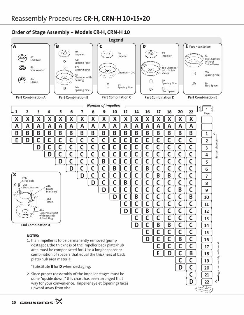
NOTES: 1. If an impeller is to be permanently removed (pump
destaged), the thickness of the impeller back plate/hub area must be compensated for. Use a longer spacer or combination of spacers that equal the thickness of back plate/hub area material.
*Substitute E for D when destaging.
2. Since proper reassembly of the impeller stages must be done "upside down," this chart has been arranged that way for your convenience. Impeller eyelet (opening) faces upward away from vise.
Legend
Part Combination A Part Combination B Part Combination C
Order of Stage Assembly – Models CR-H, CRN-H 10
Part Combination E
Beg
in r
eass
emb
ly o
n t
his
en
dB
otto
m c
ham
ber
1 2 3 4 5 6 7 8 9 10 12 14 16 17 18 20 22Number of impellers
BCC
AX
BD
BE
DD
D
AX
BAX
C CBAX
C
BAX
CCC
BAX
CCCC
BAX
CCCCCDD
DD
D
D
BAX
CCCCCC
BAX
CCCBCCC
BAX
CCCCBCCC
BAX
CCCCCCBCCC
CCD
BAX
CCCCCCCCBC
BAX
CCCCBCCCCC
BAX
CCCCCBCCCCCCB
BAX
CCCCCBCCCCCCB
C C CD C C
C C CE D C
BAX
CCCCCCCBCCCCCCB
BAX
CCCCCCCCBCCCCCCC
C CD C
CD
B
123456789
10111213141516171819202122
X
A
64Spacing Pipe
4Chamber - CPL
49Impeller
C
69aSpacing Pipe
E (*see note below)
69Spacing Pipe
DB
61Stop Spacer
Part Combination D
61Stop Spacer
End Combination X
66Star Washer
64cClamp
67Lock Nut
3aTop Chamberwithout Guide Vanes
26cStrap Washer
26bStrap Bolt
44bLower Inlet Part
44aUpper Inlet part with Retainer & Seal Ring
3Top Chamberwith GuideVanes
49Impeller
64aSpacing Pipe
64dSpacing Pipe
49Impeller
47aBearing Ring
4aChamber withBearing
26aStrap
20
Stages

Legend
Part Combination A Part Combination B- Part Combination B
Order of Stage Assembly – Models CR-H, CRN-H 10 (Low NPSH)
Part Combination D
3 4 5 6 7 8 9 10 12 14 16 17 18 20 22Nameplate number of impellers
A
64aSpacing Pipe
64dSpacing Pipe
49Impeller
3TopChamberwith Guide Vane
D
64Spacing Pipe
CB-
Part Combination C
Part Combination E
66Lock Washer
64cClamp
67Nut 49
Impeller
3aTopChamberwithout Guide Vane
69aSpacing Bush
4Chamber
49Impeller
4bChamber
49iImpeller Low NPSH
64eSpacing Pipe
61Stop Spacer
Reassembly Procedures CR-H, CRN-H 10•15•20
21
Stages
123456789
10111213141516171819202122
Beg
in r
eass
emb
ly o
n t
his
en
dB
otto
m c
ham
ber
NOTES: 1. If an impeller is to be permanently removed (pump destaged), the thickness of the
impeller back plate/hub area must be compensated for. Use a longer spacer or combination of spacers that equal the thickness of back plate/hub area material.
*Substitute E for D when destaging.
2. Since proper reassembly of the impeller stages must be done "upside down," this chart has been arranged that way for your convenience. Impeller eyelet (opening) faces upward away from vise.
3. Because the low NPSH chamber and impeller are twice the thickness of a standard chamber, it has the performance of two impellers. Physically, there is one less chamber in a stack than the number of stages listed on the pump label (example: CR-H 10-22 only has 21 chambers and impellers).
64bSpacing Pipe
4aChamber withBearing
47aBearing Ring
B
69Spacing Pipe
6Stop Spacer
X
End Combination X
26bScrew
26cWasher
26aStrap
44cInlet Part Upper
44bInlet Part Lower
44dSpacerRing
E (*see note below)
CBC
AX
B-BD
B-BE C
CDD
DD
DD
C
C
D
D
D
D
D
C
AX
B-AX
B BB-AX
C
B-AX
BCC
B-AX
BCCC
B-AX
BCBCCCC
CC
C
C
E
C
C
C
C
C
B-AX
BCCBCC
B-AX
BCCCCBC
B-AX
BCCCCCCB
B-AX
BCCCCCCCCB
CBC
B-AX
BCCCCBCCCC
B-AX
BCCCCBCCCC
B-AX
BCCCCCBCCCCCC
B-AX
BCCCCCCCBCCCC
C B CC C C
C BC
D
CC
C

Legend
Part Combination A
Order of Stage Assembly – Models CR-H, CRN-H 15 & 20
Reassembly Procedures CR-H, CRN-H 10•15•20
NOTES: 1. If an impeller is to be permanently removed (pump
destaged), the thickness of the impeller back plate/hub area must be compensated for. Use a longer spacer or combination of spacers that equal the thickness of back plate/hub area material.
*Substitute E for D when destaging.
2. Since proper reassembly of the impeller stages must be done "upside down," this chart has been arranged that way for your convenience. Impeller eyelet (opening) faces upward away from vise.
Part Combination A-
A-
66Lock Washer
64cClamp
67Nut
64dSpacing Pipe
A
66Star Washer
64cClamp
67Lock Nut
Part Combination B
B
64aSpacing Pipe
64dSpacing Pipe
49Impeller
47aBearing Ring
4aChamber withBearing
Part Combination C
64Spacing Pipe
4Chamber - CPL
49Impeller
C
Part Combination B-
B-
64fSpacing Pipe
64dSpacing Pipe
49Impeller
47aBearing Ring
4aChamber withBearing
Part Combination EPart Combination D
69aSpacing Pipe
E (*see note below)
69Spacing Pipe
D
61Stop Spacer
61Stop Spacer
3Top Chamberwith GuideVanes
49Impeller
X
End Combination X
26cStrap Washer
26bStrap Bolt
44bLower Inlet Part
44aUpper Inlet part with Retainer & Seal Ring
26aStrap
D
B-A-X
E DBA-X
BAX
CD
BA-X
CCD
BAX
CCCD
BA-X
CCCCD
BAX
CCBCCD
BA-X
CCCBCCD
BAX
CCCCBCCD
BAX
CCCCCBCCD
BA-X
CCCBCCCBCC
BAX
CCCCBCCCCBCCD
BAX
CCCCCCBCCCCCBCCD
1 2 3 4 5 6 8 9 10 12 14 177
Number of impellers
Stages
1234567891011121314151617B
egin
rea
ssem
bly
on
th
is e
nd
Bot
tom
ch
amb
er
22
3aTop ChamberwithoutGuide Vanes
-
C

Reassembly Procedures CR-H, CRN-H 10•15•20
Legend
Part Combination A Part Combination A- Part Combination A+
Order of Stage Assembly – Models CR-H, CRN-H 15 & 20 (low NPSH)
Part Combination B
A A-
Part Combination B-
NOTES: 1. If an impeller is to be permanently removed (pump destaged), the
thickness of the impeller back plate/hub area must be compensated for. Use a longer spacer or combination of spacers that equal the thickness of back plate/hub area material.
*Substitute E for D when destaging. 2. Since proper reassembly of the impeller stages must be done
"upside down," this chart has been arranged that way for your convenience. Impeller eyelet (opening) faces upward away from vise.
3. HM = Hard Metal - Tungsten Carbide 4. SiC = Sintered Silicon Carbide
A+
66Lock Washer
67Nut
64cClamp
64eSpacing Pipe
47aBearing Ring, HM
64eSpacing Pipe
64bSpacing Pipe
66Lock Washer
67Nut
64eSpacing Pipe
64cClamp
Part Combination EPart Combination D
69aSpacing Pipe
E (*see note below)
69Spacing Pipe
D
61Stop Spacer
61Stop Spacer
3Top Chamberwith GuideVanes
49Impeller
X
End Combination X
26cStrap Washer
26bStrap Bolt
44bLower Inlet Part
44a Upper Inlet part with Retainer & Seal Ring
26aStrap
D
B-A-X
E DB-A-X
B-A+X
CD
B-A-X
CCD
B-A+X
CCCD
B-A-X
CCCCD
B-A+X
CCBCCD
B-AX
CCCBCCD
B-AX
CCCCBCCD
B-A-X
CCCCCBCCD
B-A-X
CCCBCCCBCC
B-A-X
CCCCBCCCCBCCD
B-AX
CCCCCCBCCCCCBCCD
1 2 3 4 5 6 8 9 10 12 14 177
Number of impellers
Stages
1234567891011121314151617B
egin
rea
ssem
bly
on
th
is e
nd
Bot
tom
ch
amb
er
3aTop Chamberwithout Guide Vanes
64aSpacing Pipe
64bSpacing Pipe
49iImpellerLow NPSH
4aChamber withBearing
47aBearing Ring,SiC
B-
64aSpacing Pipe
64dSpacing Pipe
49Impeller
4aChamber withBearing
47aBearing Ring,SiC
B
47aBearing Ring, HM64eSpacing Pipe
66Lock Washer
67Nut
64cClamp
64eSpacing Pipe
64bSpacing Pipe
47aBearing Ring, HM
64eSpacing Pipe
23
- +-- A+ A

L-SM-DR-102 05/09PRINTED IN USA
Being responsible is our foundation
Thinking ahead makes it possibleInnovation is the essence
GRUNDFOS Pumps Corporation17100 W. 118th TerraceOlathe, Kansas 66062Phone: 913.227.3400Fax: 913.227.3500
www.grundfos.com
GRUNDFOS Canada, Inc.2941 Brighton RoadOakville, Ontario L6H 6C9 CanadaPhone: 905.829.9533Fax: 905.829.9512
Bombas GRUNDFOS de Mexico S.A. de C.V.Boulevard TLC No. 15Parque Industrial Stiva AeropuertoApodaca, N.L. Mexico 66600Phone: 52.81.8144.4000Fax: 52.81.8144.4010