growth of serpentine carbon nanotubes on quartz substrates and
TRANSCRIPT

Growth of Serpentine Carbon Nanotubes on QuartzSubstrates and Their Electrical Properties
Seokwoo Jeon1, 2, 3, Changgu Lee2, 3, Jinyao Tang1, 3, James Hone2, 3( ), and Colin Nuckolls1, 3( )
1 Department of Chemistry, Columbia University, New York, NY 10027, USA2 Department of Mechanical Engineering, Columbia University, New York, NY 10027, USA3 The Columbia University Nanoscale Science and Engineering Center, Columbia University, New York, NY 10027, USA
Received: 29 August 2008 / Revised: 25 September 2008 / Accepted: 25 September 2008
©Tsinghua Press and Springer-Verlag 2008. This article is published with open access at Springerlink.com
00427Nano Res (2008) 1: 427 433DOI 10.1007/s12274-008-8044-1 Research Article
Address correspondence to Colin Nuckolls, [email protected]; James Hone, [email protected]
ABSTRACT A simple method for high-yield, chemical vapor deposition (CVD) synthesis of serpentine carbon nanotubes, employing quartz substrates and a molecular cluster catalyst, is described. The growth mechanism is analyzed by controlled addition of nanoscale barriers, and by mechanical analysis of the curved sections. The serpentine structures are used to study the electrical transport properties of parallel arrays of identical nanotubes, which show three-terminal conductance that scales linearly with the number of nanotube segments.
KEYWORDSAligned carbon nanotube, chemical vapor deposition growth, quartz substrate, electronics
Carbon nanotubes (CNTs) are exceptional materials that possess superior electrical properties and chemical functionalities [1, 2]. Their small diameter and mechanical robustness render them useful for flexible and wearable electronics applications [35]. Recent studies using chemical vapor deposition (CVD) growth, using substrates such as sapphire [6, 7] and quartz [8], have demonstrated highly aligned CNTs over large areas, limited only by the size of substrates and the CVD chamber. Compared to sapphire, quartz substrates offer a much cheaper alternative that has the added advantage of having a more stable template along its [1120] step edge direction when the (1101) surface is exposed [8]. The growth gives dense, template assisted CNTs in a “wake-growth” mechanism where the metal
nanoparticles move in parallel to the step edge and leave the CNTs behind [9]. The average density and length of the aligned CNT depend on metal catalyst and growth parameter.
There are reports that template assisted growth of CNTs is not affected by the direction of the carbon feedstock flow gas [8, 9]. It is incongruous that the CNT growth would have the extreme sensitivity of step height to growth, but not to the direction of gas flow. In fact, we have observed various shapes of CNTs (serpentine, loop, etc.) when the quartz step edge direction does not parallel to the flow direction. Here we detail our studies of template assisted growth of serpentine CNTs and electrical measurements from those tubes. The method of making the serpentine CNTs is simple and the yield
428 Nano Res (2008) 1: 427 433
Nano Research
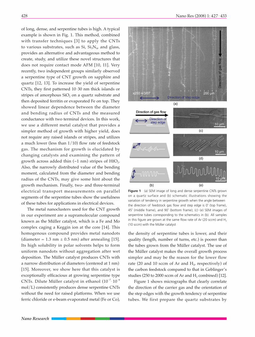
of long, dense, and serpentine tubes is high. A typical example is shown in Fig. 1. This method, combined with transfer techniques [3] to apply the CNTs to various substrates, such as Si, Si3N4, and glass, provides an alternative and advantageous method to create, study, and utilize these novel structures that does not require contact mode AFM [10, 11]. Very recently, two independent groups similarly observed a serpentine type of CNT growth on sapphire and quartz [12, 13]. To increase the yield of serpentine CNTs, they fi rst patterned 10 30 nm thick islands or stripes of amorphous SiO2 on a quartz substrate and then deposited ferritin or evaporated Fe on top. They showed linear dependence between the diameter and bending radius of CNTs and the measured conductance with two terminal devices. In this work, we use a different metal catalyst that provides a simpler method of growth with higher yield, does not require any raised islands or stripes, and utilizes a much lower (less than 1/10) fl ow rate of feedstock gas. The mechanism for growth is elucidated by changing catalysts and examining the pattern of growth across added thin (~1 nm) stripes of HfO2. Also, the narrowly distributed value of the bending moment, calculated from the diameter and bending radius of the CNTs, may give some hint about the growth mechanism. Finally, two- and three-terminal electrical transport measurements on parallel segments of the serpentine tubes show the usefulness of these tubes for applications in electrical devices.
The metal nanoclusters used for the CNT growth in our experiment are a supramolecular compound known as the Müller catalyst, which is a Fe and Mo complex caging a Keggin ion at the core [14]. This homogenous compound provides metal nanodots (diameter = 1.3 nm ± 0.5 nm) after annealing [15]. Its high solubility in polar solvents helps to form uniform nanodots without aggregation after wet deposition. The Müller catalyst produces CNTs with a narrow distribution of diameters (centered at 1 nm) [15]. Moreover, we show here that this catalyst is exceptionally effi cacious at growing serpentine type CNTs. Dilute Müller catalyst in ethanol (10 7 10 8 mol/L) consistently produces dense serpentine CNTs without the need for raised platforms. When we use ferric chloride or e-beam evaporated metal (Fe or Co),
Figure 1 (a) SEM image of long and dense serpentine CNTs grown on a quartz surface and (b) schematic illustrations showing the variation of tendency in serpentine growth when the angle betweenthe direction of feedstock gas fl ow and step edge is 0˚ (top frame), 45˚ (middle frame), and 90˚ (bottom frame); (c) (e) SEM images of serpentine tubes corresponding to the schematics in (b). All samples in this fi gure are grown at the same fl ow rate of Ar (20 sccm) and H2 (10 sccm) with the Müller catalyst
the density of serpentine tubes is lower, and their quality (length, number of turns, etc.) is poorer than the tubes grown from the Müller catalyst. The use of the Müller catalyst makes the overall growth process simpler and may be the reason for the lower flow rate (20 and 10 sccm of Ar and H2, respectively) of the carbon feedstock compared to that in Geblinger’s studies (250 to 2000 sccm of Ar and H2 combined) [12].
Figure 1 shows micrographs that clearly correlate the direction of the carrier gas and the orientation of the step edges with the growth tendency of serpentine tubes. We first prepare the quartz substrates by

429Nano Res (2008) 1: 427 433
cleaving them from a wafer (Hoffman Materials, Inc.) to the desired orientation and annealing them in air at 900 ˚C for ~8 h. The catalyst solution is quickly spread at one edge of the quartz substrate with a cotton swab and the sample is placed in a 1-inch quartz tube for oxidation for one hour at 500 °C. After purging with Ar, a mixture of 300 sccm Ar and 100 sccm H2 reduces the nanoparticles at 750 °C for 1 h. Once the temperature is raised to 880 °C, we pass 20 sccm of Ar and 10 sccm of H2 through an ethanol bubbler in an ice bath to supply the carbon source for the CNT growth for ~30 min. Figure 1(a) shows a typical scanning electron micrograph (SEM) from such a growth. Many of the CNTs are longer than 3 mm and contain both straight and serpentine segments. Depending on the angle between the direction of gas flow and the step edge of substrate (0˚ for Fig. 1(c), 45˚ for Fig. 1(d), and 90˚ for Fig. 1(e)), the shape and growth tendency of the serpentine CNTs are signifi cantly changed. More than 50 continuous turns of serpentine CNTs are frequently observed from 90˚samples, but it is rare to find more than 20 turns of continuous, regularly spaced ones from 45˚ samples and more than 2 turns from 0˚ samples. Also, the length of straight segments before the turns are ~5 15 μm for 90˚ samples and ~10 30 μm for 45˚ samples. These results strongly imply that growth mechanism is related to the fl ow of feedstock gas.
Geblinger and coworkers propose a “falling spaghetti” [12] growth mechanism for the serpentine tubes. In this mechanism, the CNT is tip-grown and becomes buoyant over the substrate along the direction of gas flow, which induces tension in the suspended CNT. After approaching a certain critical length, the CNT falls and initiates a rapid oscillatory motion, providing a competition between the flow-induced tension and the adhesion between the CNT and substrate. The morphology of some of the serpentines supports this mechanism. The straight segments of the serpentine tubes become wider, but the spacing of the straight segments becomes narrower along the direction of growth. The “falling spaghetti” mechanism explains this behavior because compared to the initial length of the buoyant CNTs, the shorter length of the suspended CNTs during serpentine motion decreases the tension from the gas
fl ow. Considering a laminar fl ow on the substrate, the loss of tension would be very fast at the end. We also frequently observe this correlation in our experiments, but as can be seen in Fig. 1 it is not universal. Because of this apparent inconsistency, we report here our investigation into the mechanism of the growth.
Tension from the buoyant part of CNTs during growth is a key to explain the mechanism of growth, and in particular explains why the serpentine CNTs always curve toward the flow direction. The turns of Fig. 1(c), are rather unexpected when the CNT is in tension toward the flow direction, but possible if the flow inside the quartz tube is not in steady state and the falling of the CNT is a fast, non-equilibrium phenomenon. It is also important to note that such turns are never observed from template assisted growth of dense, aligned CNTs [8, 9], which typically uses e-beam evaporated Fe or Co, indicating that catalyst concentration can affect the growth mechanism. The effects of catalyst density are shown explicitly in Fig. 2(a). CNTs in this sample are grown by the catalysis of a 1:10 solution of FeCl3 and ethanol. The diagonal white stripe in Fig. 2(a) is where ferric chloride is in high concentration due to aggregation during drying. Growth from the region of the concentrated catalyst is extremely straight and dense, similar to highly aligned tubes from a “wake-growth mechanism” [8, 9]. The growth of serpentine CNTs is mostly initiated from locations where catalyst is sparse and isolated. This observation explains why one cannot fi nd the effect of fl ow from normal aligned growth and such turns in Fig. 1(c). A well spaced catalyst such as the Müller catalyst does not make CNTs bundle and seems to promote the buoyancy of tip-grown tubes which is the initial step of the “spaghetti falling mechanism”.
To further understand the growth mechanism, we fabricated barriers on a quartz surface that are high enough to discourage growth parallel to the step edge but low enough not to affect the tip-growth of buoyant CNTs. HfO2 stripes with a width of 50 μm and height of 1 nm, and 150 μm pitch, were deposited parallel to the direction of the step edge through atomic layer deposition. If the growth of mechanism serpentines were solely from wake-growth, all the serpentine would stop growing at the barrier. Interestingly, the

430 Nano Res (2008) 1: 427 433
Nano Research
CNTs grow over the HfO2 layer. Figure 2(b) shows that a segment of serpentine loses its track at the boundary and Fig. 2(c) shows that serpentine tubes become straight on top of the HfO2 and then resume lateral undulation again. This behavior is strong support for the ”spaghetti falling mechanism” for serpentine CNTs. Another observation, which is consistent with the work of Geblinger and coworkers [12], is that higher fl ow rates (>100 sccm) under our growth conditions reduce the yield of serpentines. However, control experiments that change the
speed of gas fl ow after closing the feedstock bubbler seemingly do not affect the yield or overall shape of serpentine growth, in contrast to their observation.
Figure 3 presents results of atomic force microscopy (AFM) and SEM measurements of the CNT diameter (d) and the bending radius (R). As expected, we observe that the larger diameter CNTs give larger curvatures. More interestingly, the derived values of d3/2R , which is proportional to the internal bending moment of a curved cylindrical beam, are similar for many of the serpentines. The values of d3/2R are ~2 when the diameters of CNT are smaller than 2 nm (Table 1). However, the values jump to ~7 when the diameter is larger than 2 nm. This may imply the latter tubes are multi-wall tubes. The calculated energy to bend a floating CNT is ~1000 times smaller (~1 meV/nm, d=1.4 nm) than the van der Waals energy (2 eV/nm, d=1.4 nm) between the quartz substrate and the CNT [12]. We see similar behaviors when we measure the quartz surface with force displacement measurement using AFM. This fact again supports our observation that no serpentines, nor even a single turn, can be found from the growth modes of dense, aligned CNTs in Fig. 2(a); non-buoyant wake-growth tubes cannot overcome the strong adhesion energy to derail. From this, one may assume the internal bending moment plays a key role in determining the value of the bending radius. However, another interesting observation is the change of serpentine frequency even in a single tube. The change of serpentine frequency is abrupt not
Figure 2 (a) SEM image of CNTs grown from ferric chloride showing two distinctive modes of growth: highly straight growth along the direction of step edge and erratic growth along the direction of gas fl ow; (b), (c) SEM images of serpentine growth over the barrier of 1 nm thick HfO2 (gray stripes). A serpentine tube loses its motion of lateral undulation on the barrier (center stripe in (b)), or goes over the barrier and resumes serpentine movement (c)
Sample d (nm) 2R (µm) d3/(2R)
1 1.2 0.878 1.97
2 2.5 2.17 7.20
3 2.6 2.5 7.03
4 1.6 1.53 2.68
5 1.2 0.862 2.00
6 1.2/1.2 0.835/1.24 2.07/1.39
7 1.3/1.3 1.03/1.32 2.13/1.66
Table 1 Table of measured diameter (d) of CNTs from AFM and radius of bending (R) from SEM. Data for Sample 3 are measured from images of Fig. 3(a) and data of smaller bending radius in Sample 6 are from images of Fig. 3(b). Figure 3(c) corresponds to Sample 7. The bending radius obtained by SEM is the average value of more than 3 adjacent turns, and the diameter of CNT obtained by AFM is the average value of height measurement from more than 3 adjacent CNTs

431Nano Res (2008) 1: 427 433
components such as resistive heaters, resonant antennae, and many others if they can be transferred at specifi c locations on selected substrates. In addition, these structures allow us to address fundamental questions of device scaling and design. Specifically, because the theoretical limit of conductance through a single nanotube is low due to quantum resistance of CNTs (~6 kΩ/tube), many useful CNT devices will require parallel arrays of nanotubes [16] to minimize the device impedance. However, it has not been experimentally verifi ed that such arrays can be treated as a simple parallel circuit in which the conductances are simply added.
The inset to Fig. 4 shows three two-terminal devices consisting of multiple sections of a single serpentine CNT, fabricated directly on the quartz substrate by electron beam lithography and liftoff of Pd. As shown in Fig. 4, the device conductance scales linearly with the number of nanotube sections between the leads, with a constant two-terminal resistance of ~300 kΩ/tube for all three devices.
To examine the three-terminal behavior of these structures, serpentine CNTs were first transferred to a degenerately-doped silicon wafer with a 300- nm SiO2 epilayer, followed by device fabrication as described above (Fig. 5, inset). The transfer process consists of mechanically peeling off thin films of CNTs supported by ~50 nm gold and a fl exible water soluble polymer (PVA), contacting it to the Si wafer,
Figure 3 (a), (b) Representative SEM and AFM images of serpentine tubes with large (>2 µm) and small (<1 µm) diameter of bending; (c) SEM of CNT which significantly changes its bending diameter from 1.32 to 1.03 µm (from right to left)
Figure 4 I V plots from two-terminal devices made over a serpentine tube on a quartz substrate. Three different numbers (2, 5, and 14) of CNTs are bridging four contact leads (I, II, III, and IV) as shown in the inset image
gradual, as shown in Fig. 3(c). The left part has higher frequency of serpentine movement, and the right part has lower frequency. The sections have similar tube diameter within experimental error but differ in radius of curvature (Sample 7 in Table 1), by ~30 %;even still, the value of the curvature does not affect the value of d3/(2R) much as do the values for larger diameter CNTs (Samples 2 and 3 in Table 1). These observations mean that the internal bending moment has a certain contribution to the radius of curvature, but is not the determining factor because of non-steady nature of the serpentine growth as reported by Geblinger et al. [12].
The serpentines and rings shown in this paper can be useful for the fabrication of nanoelectronic

432 Nano Res (2008) 1: 427 433
Nano Research
and etching away the polymer and gold (details of the transfer method can be found elsewhere [3, 5]). Figure 5 shows a plot of the current vs gate voltage for three devices, with 5, 10, and 13 parallel sections, at a constant bias of 10 mV. All three devices show p-type semiconducting behavior, with good on-off ratio (>104), turn-on voltage around 2.5 V, and typical hysteresis between up- and down-sweeps [17]. Figure 5(b) shows the conductance per nanotube segment for all three devices. The 5- and 13-tube devices show virtually identical behavior (the estimated value of mobility [5] from these devices are 1000 cm2/(V·s)).
Figure 5 (a) Plot of gate sweep under 0.01 V of applied source to drain voltage from a back gate device. Three different numbers (5, 10, and 13) of CNTs are connected to four contact leads (I, II, III, and IV) as shown in the inset image of (b). The device mades of 10 bridged tubes cannot be turned off completely. (b) Normalized plot of (a) per tube value. Leakage current from the device of 10 bridged tubes is deducted for better comparison
The 10-tube device differs slightly, but this is likely due to the presence of a parasitic conduction channel through a spurious additional tube. The data confirm the expected scaling of device resistance with number of nanotube channels. In addition, the identical subthreshold behavior of the devices shows that all of the nanotube sections possess identical transfer characteristics (i.e., threshold voltage and transconductance), and demonstrates that parallel array CNT-FETs can achieve the same high performance as individual nanotubes. With this method, one can easily get many parallel CNTs with the same chirality and diameter. We have fabricated devices with on-state resistances as low as ~800 Ω in this manner.
In conclusion, combined effects from flow direction of carbon feedstock gas and step direction of quartz substrate can promote growth of various shapes of CNTs and the angles between those directions play an important role in determining the overall shapes of grown CNTs. The use of the Müller catalyst forms uniform and well distributed metal nanoparticles on a quartz surface that enables us to achieve long, high yield serpentine tubes. The dominant growth mechanism of serpentine tubes is not wake-growth, but a combination of buoyant growth and a falling mechanism. The observed narrow distribution of bending moments, obtained from the analysis of bending radius and diameter of the CNTs, supports the proposed growth mechanism. Electrical measurements on CNT arrays show linear scaling of the three-terminal electronic transport with the number of tubes, without any extrinsic broadening or other effects. The level of control over the growth and interesting electronic properties promise this technique will offer a useful tool to characterize electric and mechanical properties of CNTs and to fabricate new CNT-based devices.
Acknowledgements
This work is supported by the Nanoscale Science and Engineering Initiative of the National Science Foundation under NSF Award Number CHE-0117752 and by the New York State Office of Science, Technology, and Academic Research (NYSTAR).
433Nano Res (2008) 1: 427 433
References
[1] Jorio, A.; Dresselhaus, M. S.; Dresselhaus, G. Carbon
Nanotubes; Springer: New York, 2008.
[2] O'Connell, M. J. Carbon Nanotubes: Properties and
Applications; CRC Press: Boca Raton, 2006.
[3] Ahn, J. -H.; Kim, H. -S.; Lee, K. J.; Jeon, S.; Kang, S. J.;
Sun, Y.; Nuzzo, R. G.; Rogers, J. A. Heterogeneous three-
dimensional electronics by use of printed semiconductor
nanomaterials. Science 2006, 314, 1754 1757.
[4] Dondero, W.; Gorga, R. E. Carbon nanotubes. In
Handbook of Nanoscience, Engineering, and Technology,
2nd ed.; Goddard, W. A.; Brenner, D. W.; Lyshevski, S.
E.; Iafrate, G. J., Eds; CRC Press: Boca Raton, 2007, pp.
21/27 21/37.
[5] Kang, S. J.; Kocabas, C.; Ozel, T.; Shim, M.; Pimparkar,
N.; Alam, M. A.; Rotkin, S. V.; Rogers, J. A. High-
performance electronics using dense, perfectly aligned
arrays of single-walled carbon nanotubes. Nature
Nanotech. 2007, 2, 230 236.
[6] Ago, H.; Nakamura, K.; Ikeda K. -I.; Uehara, N.; Ishigami,
N.; Tsuji, M.; Aligned growth of isolated single-walled
carbon nanotubes programmed by atomic arrangement
of substrate surface. Chem. Phys. Lett. 2005, 408, 433
438.
[7] Ismach, A.; Kantorovich, D.; Joselevich, E. Carbon
nanotube graphoepitaxy: Highly oriented growth by
faceted nanosteps. J. Am. Chem. Soc. 2005, 127, 11554
11555.
[8] Kocabas, C.; Hur, S. -H.; Gaur, A.; Meitl, M. A.; Shim M.;
Rogers, J. A. Guided growth of large-scale, horizontally
aligned arrays of single-walled carbon nanotubes and
their use in thin-film transistors. Small 2005, 1, 1110
1116.
[9] Ding, L.; Yuan, D.; Liu J. Growth of high-density parallel
arrays of long single-walled carbon nanotubes on quartz
substrates. J. Am. Chem. Soc. 2008, 130, 5428 5429.
[10] Hertel, T.; Martel, R.; Avouris, P. Manipulation of
individual carbon nanotubes and their interaction with
surfaces. J. Phys. Chem. B 1998, 102, 910 915.
[11] Park J. -Y. Carbon nanotube fi eld-effect transistor with a
carbon nanotube gate electrode. Nanotechnology 2007,
18, 095202.
[12] Geblinger, N.; Ismach, A.; Joselevich, E. Self-organized
nanotube serpentines. Nature Nanotech. 2008, 3, 195
200.
[13] Kocabas, C.; Kang, S. J.; Ozel, T.; Shim, M.; Rogers, J.
A. Improved synthesis of aligned arrays of single-walled
carbon nanotubes and their implementation in thin fi lm
type transistors. J. Phys. Chem. C 2007, 111, 17879
17886.
[14] Müller, A.; Das, S. K.; Kögerler, P. ; Bögge, H.;
Schmidtmann, M.; Trautwein, A. X.; Schunemann, V.;
Krickemeyer, E.; Preetz, W. A new type of supramolecular
compound: Molybdenum-oxide-based composites
consisting of magnetic nanocapsules with encapsulated
Keggin-ion electron reservoirs cross-linked to a two-
dimensional network. Angew. Chem., Int. Ed. Engl.
2000, 39, 3414 3417.
[15] An, L.; Owens, J. M.; McNeil, L. E.; Liu, J. Synthesis of
nearly uniform single-walled carbon nanotubes using
identical metal-containing molecular nanoclusters as
catalysts. J. Am. Chem. Soc. 2002, 124, 13688 13689.
[16] Keshavarzi, A.; Raychowdhury, A.; Kurtin, J.; Roy, K.;
De, V. Carbon nanotube field-effect transistors for
high-performance digital circuits transient analysis,
parasitics, and scalability. IEEE Trans. Electron Devices
2006, 53, 2718 2726.
[17] Lee, J. S.; Ryu, S.; Yoo, K.; Choi, I. S.; Yun, W. S.; Kim, J.
Origin of gate hysteresis in carbon nanotube fi eld-effect
transistors. J. Phys. Chem. C 2007, 111, 12504 12507.