growth mechanism of carbon nanotubes deposited by electrochemical
TRANSCRIPT

Indian Journal of Pure & Applied Physics Vol. 43, October 2005, pp. 765-771
Growth mechanism of carbon nanotubes deposited by electrochemical technique
S K Mandal, S Hussain & A K Pal* Department of Instrumentation Science, Jadavpur University, Calcutta 700 032
Received 25 July 2005; accepted 25 August 2005
Understanding the nucleation and growth of carbon nanotubes at room temperature by a novel electrochemical process using acetonitrile as the electrolyte is investigated here. Microscopic insight into the nucleation process clearly reveals coalescence of amorphous carbon clusters in a branched network instigated mainly by dangling-bond induced relaxation and subsequent rearrangement of carbon atoms through a quasi-liquid state leading to the formation of multi-walled carbon nanotubes. Such a direct conversion of amorphous carbon into nanotubes is not abrupt, rather driven by a slow thermodynamical process that is inherent to the electrochemical process.
Keywords: Carbon nanotubes, Growth, Electrodeposition IPC Code: C25,B82B
1 Introduction The fascinating structural and electronic properties of carbon in its various forms like amorphous carbon, diamond like carbon, graphite, diamond etc. led to a flurry of research activities over the years1-6. The versatility of carbon in various phases stems from its ability to rehybridize between sp, sp2 and sp3 bonds. Amongst its various forms, the most fascinating one is the tubule one, called carbon nanotube, which is primarily thought of as a rolled-on graphene sheet with sp2 bonded carbon atoms. Since the pioneering work done by Iijima7, intense research activities were witnessed so far to understand the growth, structural and electronic aspects of carbon nanotubes having a variety of applications8-15. Generally, the synthesis of these tubes involved high temperature catalytic growth of carbon (graphite) achieved through various processes like carbon arc discharge11,16,17, laser ablation18,19, CVDs20,22 etc. Depending on the growth conditions, the tubes would evolve as single-walled, multi-walled, bundles with distribution in diameters, different chiralities, defects and kinks which in turn controlled their electronic features in metallic as well as in semiconducting phase. Despite a large number of theoretical and experimental investigations10,23-28 on the microscopic insight to the growth of single-walled as well as multi-walled carbon nanotubes, the issue is still not clearly understood and wide open for critical investigations. Nevertheless, there is a large consensus between theoretical models and experimental results.
In contrast to the conventional high temperature (~2000-4000°C) catalytic growth, we have recently reported an off-the-shelf approach to synthesis carbon nanotubes by a simple electrochemical process29. A key aspect of this novel approach was the growth of carbon nanotubes at room temperature without the presence of any metal catalysts and could be directly deposited onto suitable substrates. The process was not abrupt one, rather involved a number of phase transformations of carbon with electrodeposition time leading to the growth of carbon nanotubes which generated much curiosity. In this paper, an attempt is made to understand this unique growth process of the tubes through microscopic and spectroscopic investigations. It was observed that the initial nucleation layers consisted of amorphous carbon that subsequently converted into tubular form through a quasi-melting process. In the intermediate steps, various carbon structures like network of carbon flakes, aggregated carbon particles in cage like form were also found to occur. We describe here systematically how the coordination of carbon atoms results into sp2 bonded carbon network forming carbon tubes. The local fluctuations in thermal environment due to the dissociation of C-H bonds might possibly have a strong consequence in determining the growth of various carbon structures. 2 Experimental Details In the electrochemical approach29, acetonitrile (CH3CN, 1% in volume) in distilled water was used as the electrolyte. The deposition took place at room temperature under the application of a significantly
___________ *E mail: [email protected]
INDIAN J PURE & APPL PHYS, VOL 43, OCTOBER 2005
766
lower voltage of 16 V between the substrate and counter electrode (graphite). Both tin-oxide-coated glass and Si (001) were used as the substrate placed on the working electrode. The post-deposition growth of the films on the substrate was monitored by electron microscopy at an interval of one hour till the formation of carbon nanotube after a deposition period of four hours. The films obtained at intermediate duration were found to have carbon in its amorphous phase (a-C) which subsequently converted into carbon nanotube structures. We discuss this systematic growth of carbon nanotube from initial amorphous carbon layers at room temperature based on electron microscopic investigations. The in situ growth and nucleation of carbon nanotube films were characterized by Raman (Horiba U-1000), Fourier Transform Infrared (FTIR) Spectroscopy (Nicolet, MAGNA-IR-750), X-Ray Photoelectron Spectroscopy (XPS) (Perkin-Elmer, PHI-1257), Scanning Electron Microscope (SEM, Hitachi S-2300) and Transmission Electron Microscope (TEM, JEOL 2010F, UHR) respectively. 3 Results and Discussion Scanning electron microscopic (SEM) images of carbon structures on Si obtained at intervals of one hour since the deposition started (t=0) are presented in
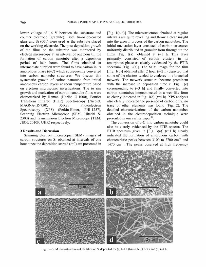
[Fig. 1(a-d)]. The microstructures obtained at regular intervals are quite revealing and throw a clear insight into the growth process of the carbon nanotubes. The initial nucleation layer consisted of carbon structures uniformly distributed in granular form throughout the films [Fig. 1(a)] obtained at t=1 h. This layer primarily consisted of carbon clusters in its amorphous phase as clearly evidenced by the FTIR spectrum [Fig. 2(a)]. The SEM image for the film [Fig. 1(b)] obtained after 2 hour (t=2 h) depicted that some of the clusters tended to coalesce in a branched network. The network structure became prominent with the increase in deposition time t [Fig. 1(c) corresponding to t=3 h] and finally converted into carbon nanotubes interconnected in a web-like form as clearly indicated in Fig. 1(d) (t=4 h). XPS analysis also clearly indicated the presence of carbon only, no trace of other elements was found (Fig. 2). The detailed characterizations of the carbon nanotubes obtained in the electrodeposition technique were presented in our earlier paper29. The conversion of a-C into carbon nanotube could also be clearly evidenced by the FTIR spectra. The FTIR spectrum given in [Fig. 3(a)] (t=1 h) clearly indicated the formation of amorphous carbon with characteristic peaks between 3100 to 2700 cm−1 and 1470 cm−1. The peaks observed at high frequency
Fig. 1—SEM microstructures of the films on Si deposited for (a) t=1 h (b) t=2 h (c) t=3 h and (d) t=4 h

MANDAL et al.: GROWTH MECHANISM OF CARBON NANOTUBES
767
(2931-3100 cm−1) were typical of sp2 hybridized carbon and were more intense than the peak at 2870 cm−1 corresponding to sp3 hybridized carbon. With the progress in deposition time, the peaks at the low frequency range becomes prominent corresponding to the vibrational modes of carbon nanotubes. The FTIR spectrum obtained for film after a deposition of t=4 h [Fig. 3(b)] indicated main features centered around 1060, 1411 and 1583 cm−1 in the lower frequency range. The broad peak at ~ 1060 cm−1 is a characteristic to Si-O-Si stretching vibrations30. The peaks centered at 1411 cm−1 and 1583 cm−1 along with other satellite peaks at 1475 cm−1, 1478 cm−1, 1606 cm−1 and 1630 cm−1 respectively may be attributed to the vibrational modes for carbon nanotubes31. Small peaks at 2854 and 2918 cm−1 in the higher frequency region of the spectra correspond to the C-H stretching vibrations of chemisorbed hydrogen and are quite weak in comparison to carbon nanotubes. The broad band centered at ~ 3400 cm−1 could be attributed to the presence of -OH groups and molecular water in the films. The growth was also critically found to be dependent on the substrate used and to ascertain the above, the films were deposited both on Si and SnO2 coated glass substrates retaining the other experimental conditions invariant. We present the SEM images of the growth of carbon structures on SnO2 coated glass substrate obtained at a regular interval of 1 hour as given in [Fig. 4(a-d)]. Although the initial nucleation layer is amorphous carbon for films deposited on Si and SiO2 substrates, the intermediate structures of the coatings on SnO2 coated
glass differed in morphology to some extent from that on silicon substrate. The whole process of conversion was not abrupt, rather involved a very slow thermodynamically or chemically motivated kinetics leading to the various carbon microstructures and finally to carbon nanotubes. The observed growth of carbon nanotubes from amorphous carbon clusters would raise some interesting issues on the aspects of carbon structures and its phase transitions into various allotropes: (i) what is the source of carbon here? (ii) How the amorphous carbon phase is converted into tubule structure even at room temperature? and (iii) How the tubes nucleate even without the presence of any metal catalysts?. In this case, the growth of carbon nanotubes occurred solely from the amorphous carbon clusters as the electrodeposition progressed. This clearly suggested a different growth mechanism. Even though the melting point of any type of carbon phase is quite high, we presumed that a quasi-melting process of the
Fig. 2—XPS spectrum obtained for films on Si after a period of t= 4 h indicating the presence of carbon only
Fig. 3—FTIR spectra obtained for films on Si after a period of (a) t= 1 h and (b) t= 4 h

INDIAN J PURE & APPL PHYS, VOL 43, OCTOBER 2005
768
carbon clusters might lead to the formation of the tubes. This presumption is supported here by in situ microscopic investigations during the growth of carbon nanotubes. The size of the clusters and their distribution obviously played the critical role in determining the diameter and its distribution, uniformity over the length of the carbon nanotubes etc. To unveil the intriguing kinetics of the growth of carbon nanotubes from amorphous carbon clusters, HRTEM images of the films grown at very early stages of the nucleation process came to our advantage. In Fig. 5, early nucleation phases are illustrated with the TEM images of the films obtained after t=1 h [Fig. 5(a)], t=1.5 h [Fig. 5(b)] and t=2 h [Fig. 5(c)] respectively. Figure 5(a) clearly indicated the dispersed carbon clusters of typical size ~ 10 nm distributed over the entire film. Quite interestingly, as the electrodeposition progressed, the coalescence of the carbon clusters in branched network is clearly visible in [Fig. 5(b)]. Expansion of this network with time is further evidenced by the microstructure obtained after 2 h of deposition as shown in [Fig. 5(c)]. A more clear insight of the formed network is also presented in [Fig. 5(d)]. Termination of the branch at any instant of time basically controls the length of nanotubes and the extension of the network. High resolution TEM images (Fig. 6) further
revealed the formation of the multi-walled nature of the tubes with typical diameters 100-250 nm after 4h of deposition. Thus, the microstructural information obtained from the SEM studies (Figs 1 and 4) are in conformity with those depicted from the TEM studies (Fig. 5). In conventional approach, carbon nanotubes are synthesized by enriching the graphite source with single metal or mixture of transition metal catalysts and the growth takes place from amorphous carbon of condensed phase or small carbon clusters of gas phase. It is conceived that the single-walled nanotubes are produced in the presence of transition metal catalysts, however, not required for producing multi-wall nanotubes. The exact role of catalysts although had been discussed by various researchers, still remains controversial. The issue of open- or close-ended growth of nanotubes had been investigated by different theoretical models32-34. The longitudinal growth of tubes by addition of C2 dimers or C3 trimers was largely influenced by pentagon or heptagon-pentagon defects in controlling termination of tube growth and also plays a crucial role in determining the size and distribution of the tubes. In electrodeposition technique described here, the source of carbon is obviously CH3
+ radicals dissociated from acetonitrile in the electrochemical process giving rise to the formation of amorphous
Fig. 4—SEM microstructures of the films on tin-oxide coated glass deposited for (a) t=1 h (b) t=2 h (c) t=3 h and (d) t=4 h

MANDAL et al.: GROWTH MECHANISM OF CARBON NANOTUBES
769
carbon in the form of very small clusters with unsaturated dangling bonds. The dehydrogenation of carbon from CH3 radicals could be predicted through the following reactions35,36: CH3CN+H2O = CH3
+ + CN- + H+ + OH−
CH3++ CH3
++2e → CH2=CH2+H2 nCH2=CH2 → [−CH2CH2 −]n [−CH2CH2 −]n → Cn+2nH2
The carbon atoms could form chains of highly distorted carbon atoms with four-fold coordination (sp3). This highly distorted four-fold site possibly
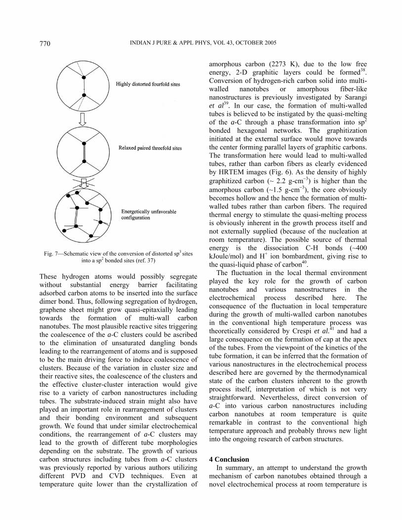
induced by surface diffusion, dangling-bond driven relaxation and topological defects etc. could relax to an undistorted sp2 configuration even at low temperature37 as shown schematically in Fig. 7. Reconfiguration of two distorted sp3 sites into a π-bonded pair was most likely to occur giving rise to the formation of graphite networks. The hydrogen may have an important role to facilitate the growth of nanotubes here. Transport of H+ ions to the cathode played an important role in the formation of initial layer of a-C phase during the growth. The presence of hydrogen at the cathode would facilitate the separation of chemically different bonded carbon regions minimizing the internal stress.
Fig. 5—TEM microstructures of the films in the electrochemical process deposited for (a) t=1 h (b) t=1.5 h (c) t= 2 h and (d) t=3 h
Fig. 6—HRTEM image of (a) a portion of multi-walled carbon nanotube (b) showing parallel fringes of the tube
INDIAN J PURE & APPL PHYS, VOL 43, OCTOBER 2005
770
These hydrogen atoms would possibly segregate without substantial energy barrier facilitating adsorbed carbon atoms to be inserted into the surface dimer bond. Thus, following segregation of hydrogen, graphene sheet might grow quasi-epitaxially leading towards the formation of multi-wall carbon nanotubes. The most plausible reactive sites triggering the coalescence of the a-C clusters could be ascribed to the elimination of unsaturated dangling bonds leading to the rearrangement of atoms and is supposed to be the main driving force to induce coalescence of clusters. Because of the variation in cluster size and their reactive sites, the coalescence of the clusters and the effective cluster-cluster interaction would give rise to a variety of carbon nanostructures including tubes. The substrate-induced strain might also have played an important role in rearrangement of clusters and their bonding environment and subsequent growth. We found that under similar electrochemical conditions, the rearrangement of a-C clusters may lead to the growth of different tube morphologies depending on the substrate. The growth of various carbon structures including tubes from a-C clusters was previously reported by various authors utilizing different PVD and CVD techniques. Even at temperature quite lower than the crystallization of
amorphous carbon (2273 K), due to the low free energy, 2-D graphitic layers could be formed38. Conversion of hydrogen-rich carbon solid into multi-walled nanotubes or amorphous fiber-like nanostructures is previously investigated by Sarangi et al39. In our case, the formation of multi-walled tubes is believed to be instigated by the quasi-melting of the a-C through a phase transformation into sp2 bonded hexagonal networks. The graphitization initiated at the external surface would move towards the center forming parallel layers of graphitic carbons. The transformation here would lead to multi-walled tubes, rather than carbon fibers as clearly evidenced by HRTEM images (Fig. 6). As the density of highly graphitized carbon (~ 2.2 g-cm−3) is higher than the amorphous carbon (~1.5 g-cm−3), the core obviously becomes hollow and the hence the formation of multi-walled tubes rather than carbon fibers. The required thermal energy to stimulate the quasi-melting process is obviously inherent in the growth process itself and not externally supplied (because of the nucleation at room temperature). The possible source of thermal energy is the dissociation C-H bonds (~400 kJoule/mol) and H+ ion bombardment, giving rise to the quasi-liquid phase of carbon40. The fluctuation in the local thermal environment played the key role for the growth of carbon nanotubes and various nanostructures in the electrochemical process described here. The consequence of the fluctuation in local temperature during the growth of multi-walled carbon nanotubes in the conventional high temperature process was theoretically considered by Crespi et al.41 and had a large consequence on the formation of cap at the apex of the tubes. From the viewpoint of the kinetics of the tube formation, it can be inferred that the formation of various nanostructures in the electrochemical process described here are governed by the thermodynamical state of the carbon clusters inherent to the growth process itself, interpretation of which is not very straightforward. Nevertheless, direct conversion of a-C into various carbon nanostructures including carbon nanotubes at room temperature is quite remarkable in contrast to the conventional high temperature approach and probably throws new light into the ongoing research of carbon structures. 4 Conclusion In summary, an attempt to understand the growth mechanism of carbon nanotubes obtained through a novel electrochemical process at room temperature is
Fig. 7—Schematic view of the conversion of distorted sp3 sites into a sp2 bonded sites (ref. 37)

MANDAL et al.: GROWTH MECHANISM OF CARBON NANOTUBES
771
presented here. The microscopic investigations at various stages of the growth clearly revealed a direct conversion of amorphous carbon into nanotubes and various nanostructures, which was solely instigated by the coalescence and subsequent quasi-melting of the carbon clusters. The quasi-liquid phase of the carbon clusters and kinetics of the consequent growth of carbon nanotubes even at room temperature revealed a new phenomenon from the thermodynamical point of view. The experimental observations and inferences would be more robust by theoretical understanding of the kinetics of the growth process, and hence to predict and control the microstructures to be obtained in the electrochemical technique. Acknowledgement The authors wish to thank the Defence Research and Development Organization (DRDO), Ministry of Defence, Government of India, for sanctioning financial assistance for executing this programme. Thanks are due to Prof. P V Satyam, Institute of Physics, Bhubaneswar, India for his assistance in recording the HRTEM micrographs. References
1 Shimakawa K & Miyake K, Phys Rev Lett, 61 (1988) 994. 2 Fink J, Muller-Heinzer-ling T, Pfluger J, Scheerer B, et al.,
Phys Rev B, 30 (1984) 4713. 3 Galli G, Martin R M, Car R & Parrinello M, Phys Rev Lett,
62 (1989) 555. 4 Geis M G, Proc IEEE, 79 (1991) 669. 5 Stephan U, Frauenheim Th, Blaudeck P & Jungnickel G,
Phys Rev B, 49 (1994) 1489. 6 Chakrabarti K, Chakrabarti R, Chaudhuri S & Pal A K, Dia
Rel Mater, 7 (1998) 1227. 7 Iijima S, Nature, 354 (1991) 56. 8 Saito S, Science, 278 (1997) 77. 9 Bachtold A, Hadley P, Nakanishi T & Dekker C, Science,
294 (2001) 1317. 10 Kwon Y -K, Lee Y H, Kim S -G, Jund P, et al., Phys Rev
Lett, 79 (1997) 2065. 11 Journet C, Maser W K, Bernier P, Loiseau A, et al., Nature,
388 (1997) 756. 12 Ajayan P M, Stephan O, Colliex C & Trauth D, Science, 265
(1994) 1212. 13 Kazaoui S, Mandal S K & Minami N, AIP Conf Proc, 633
(2002) 318.
14 Kazaoui S, Minami N, Jacquemin R, Kataura H & Achiba Y, Phys Rev B, 60 (1999) 13339.
15 Postma H W Ch, Jonge M de, Yao Z & Dekker C, Phys Rev B, 62 (2000) R10633.
16 Iijima S& Ichihashi T, Nature, 363 (1993) 603. 17 Bethune D S, Klang C H, Vries M S de, Gorman G, et al.,
Nature, 363 (1993) 605. 18 Thess A, Lee R, Nikolaev P, Dai H, et al., Science, 273
(1996) 483. 19 Cheng H M, Li F, Su G, Pan H Y, et al., Appl Phys Lett, 72
(1998) 3282. 20 Jong J, Cassell A M & Dai H, Chem Phys Lett, 292 (1998)
567. 21 Ge M & Sattler K, Science, 260 (1993) 515. 22 Yudasaka M, Tasaka K, Kikuchi R, Ohki Y & Yoshimura S,
J Appl Phys, 81 (1997) 7623. 23 Charlier J C & Iijima S, Topics Appl Phys, 80 (2001) 55 and
references therein. 24 Gavillet J, Loiseau A, Journet C, Willaime F, et al., Phys Rev
Lett, 87 (2001) 275504. 25 Kiang C –H & Goddard III W W, Phys Rev Lett, 76 (1996)
2515. 26 Maiti A, Brabec C J & Bernholc J, Phys Rev B, 55 (1997)
R6097. 27 Charlier J -C, De Vita A, Blasé X & Car R, Science, 275
(1997) 646. 28 Fan X, Buczko R, Puretzky A A, Geohegan D B, et al., Phys
Rev Lett, 90 (2003) 145501. 29 Pal A K, Roy R K, Mandal S K, Gupta S & Deb B, Thin
Solid Films, 2004 (in press). 30 Socrates G, Infrared Characteristics Group Frequencies:
Tables and Charts (John Wiley Chichester 1994). 31 Chen J, Hamon M A, Hu H, Chen Y, et al., Science, 282
(1994) 95. 32 Smalley R E, Mater Sci Eng B, 19 (1993) 1. 33 Saito R, Fujita M, Dresselhaus G & Dresselhaus M S, Mater
Sci Eng B, 19 (1993) 185. 34 Buongiorno Nardelli M, Brabec C, Maiti A, Toland C,
Bernholc J, Phys Rev Lett, 80 (1998) 313. 35 Fu Q, Jiu J -T, Wang H, Cao C –B & Zhu H S, Chem Phys
Lett, 301 (1999) 87. 36 Yan X B, Xu T, Yang S R & Xue Q J, J Phys D: Appl Phys,
37 (2004) 2416. 37 Tamor M A, Applications of Diamond Films and Related
Materials (Eds Feldman A, Tzeng Y, Yarbrough W A, Yoshikawa M, Murakawa M, NIST, Gaithensburg, p-691, 1995).
38 Abrahamson J, Carbon, 19 (1973) 217. 39 Sarangi D, Godon C, Granier A, Moalic R, et al., Appl Phys
A, 73 (2001) 765. 40 Murooka Y & Hearne K R, J Appl Phys, 43 (1972) 2656. 41 Crespi V H, Phys Rev Lett, 82 (1999) 2908.