growing architecture through mycelium and agricultural … · mycelium and agricultural waste based...
TRANSCRIPT

1
GROWING ARCHITECTURE THROUGH MYCELIUM AND AGRICULTURAL WASTE
Author: Eduardo Mayoral González Advisors: Edward Keller [email protected] Mitchell Joachim AAR, 2009_2010 Collaborator: Ecovative Design
Columbia University, GSAPP
Fig.1:
Mycelium and agricultural waste based biocomposite
0.
Abstract
Growing architectural shelters by manipulating plant growth is not a new design strategy. It is easy to find many examples in traditional architecture or arborsculpture and tree shaping. However there are more sophisticated ways of programming matter to grow 100% organic and disposable architectural devices or usable structures, not only generating cero waste, but also nutrients for the environment.
This work explores the possibilities of a material developed by Ecovative Design, which is actually being used for insulating and packaging purposes, to generate usable structures and shelters shifting its scale and slightly modifying its composition.
Keywords: growing architecture, biocomposite, Ecovative, Greensulate, insulation, structure, mycelium, agricultural waste, density, porosity, aggregation, active life cycle, re-cycling, positive impact.

2
1. Greensulate: a low-tech biocomposite. Greensulate (Fig.2) is a 100% compostable and biodegradable material made of mushroom roots (using mycelium as a resin), seed husks and agricultural waste. Eben Bayer and Gavin McIntyre, from Ecovative Design, developed this material to replace Styrofoam for packaging and insulating purposes. It uses local seeds and mushroom roots and it almost does not need energy to be fabricated since it naturally grows.
Fig.2: Greensulate Panel Ecovative Design
Greensulate performs as well as an EPS (Expanded Polystyrene) in thermal insulation terms if the thickness is increased the 15% in relation to a regular foam panel. For the same amount of material produced, it consumes about ten times less energy and produces eight times less CO2 emissions than EPS (considering fabrication and transportation processes). If it replaces foam panels for insulating purposes, the overall CO2 emission would decrease 25.000.000 Kg in two years. That means reducing energy consumption during production processes and environmental footprint as well (Tab.1).
Material 1m3 EPS 1m3 Greensulate C02 emitted 462 Kg 31 Kg
energy consumed 5000MJ 625 MJ
Tab.1: Energy consumption and CO2 emission data from Ecovative Design
A Greensulate panel has better structural properties than a foam one, since it is 20% stronger and its density is higher (Tab.2). It has a very low flammability and it resists longer than foam against fire. It does not emit toxic gases when it burns (Fig.3). Moreover it can be broken down into pieces and spread on a garden after used, being part of a biological metabolic active life cycle (Fig.4).
Fig.3: EPS and Greensulate fire prove Ecovative Design
Material EPS Greensulate Density 1-3 lbs/ft3 7 lbs/ft3 R-Value 3.5/in 3/in
Flammability High Very Low Strength 33 psi 54 psi Footprint Big Very Small
Cost 3-4 USD/ft3 2-3 USD/ft3
Tab.2: Greensulate characteristics from Ecovative Design
Fig.4: Greensulate active life cycle Ecovative Design

3
A sample of this material was sent to the Researching Technology and Innovation Centre of the University of Seville to be analyzed. The results show its composition is mainly organic (Tab.3) due to there are high calcination losses (95.53%). Diffractograms show the sample is made of 95% amorphous organic matter, and micro-textural analysis indicates it is a porous sample (Fig.5-8) (Tab.4-7).
elements K2O CaO SO3 P2O5 1,419 % 0,983 0,509 0,418
elements SiO2 MgO Cl Al2O3 0,395 % 0,285 0,230 0,090
elements Fe2O3 Na2O TiO2 BaO 0,080 % 0,037 0,008 0,004
Tab.3: Greensulate chemical composition from the Researching Technology and Innovation Centre of the University of Seville
Hence we can say the sample is biodegradable. It does not contain harmful elements for humans or the environment, and it releases a certain amount of nutrients for plant growing after used. It does not have a very long lasting life if it is placed outdoors unless it is treated and protected.
Fig.5: Greensulate diffractogram from the Researching Technology and Innovation Centre of the University of Seville
Element Weight% Atomic% C 50.42 65.89 O 27.60 27.08 Na 0.41 0.28 Mg 0.33 0.21 Al 0.24 0.14 Si 0.54 0.30 Cl 0.55 0.24 K 2.02 0.81 Ca 0.31 0.12 Fe 17.03 4.79
Totals 100.00
Element Weight% Atomic% C 58.14 71.32 O 25.21 23.22 Al 0.77 0.42 Si 0.25 0.13 K 0.48 0.18 Ca 1.18 0.44 Ti 13.98 4.30
Totals 100.00
Tab.4: Greensulate chemical composition from the Researching Technology and Innovation Centre of the University of Seville
Fig.6: Greensulate diffractogram from the Researching Technology and Innovation Centre of the University of Seville
Element Weight% Atomic% C 28.04 48.83 O 11.71 15.31 Al 24.91 19.31 Si 0.44 0.33 Cl 0.79 0.46 K 9.39 5.02 Ca 8.87 4.63 Ti 2.74 1.19 Fe 13.13 4.92
Totals 100.00 Element Weight% Atomic%
C 26.20 47.13 O 11.24 15.18 Al 23.92 19.15 Si 0.38 0.29 Cl 1.06 0.65 K 11.67 6.45 Ca 8.39 4.52 Fe 17.13 6.63
Totals 100.00
Tab.5: Greensulate chemical composition from the Researching Technology and Innovation Centre of the University of Seville

4
Fig.7: Greensulate diffractogram from the Researching Technology and Innovation Centre of the University of Seville
Element Weight% Atomic% C 5.35 11.58 O 28.32 46.06 Cl 0.28 0.21 K 1.33 0.88 Ca 62.97 40.88 Sn 1.76 0.39
Totals 100.00
Tab.6: Greensulate chemical composition from the Researching Technology and Innovation Centre of the University of Seville
Fig.8: Greensulate diffractogram from the Researching Technology and Innovation Centre of the University of Seville
Element Weight% Atomic% C 58.19 67.12 O 34.83 30.16 Na 0.57 0.34 Mg 0.36 0.21 Cl 0.88 0.34 K 5.17 1.83
Totals 100.00
Tab.7: Greensulate chemical composition from the Researching Technology and Innovation Centre of the University of Seville
The material grows inside molds in less than two weeks, preferably under moistly conditions in the dark. However people at Ecovative Design are now trying to develop a procedure using essential oils so that it can be grown outside and built in situ.
The regular set of steps needed for the material to grow consists of disinfecting the molds with hydrogen peroxide, filling them with previously boiled agricultural waste, spreading mushroom seeds on them, placing the molds inside plastic bags, and letting the mycelium grow to put all the components together. Once it is grown the only things left to do are removing the molds and drying the outcome (Fig.9).
Fig.9: Ecocradle pieces Ecovative Design
There is also the possibility to grow grass or some kind of plants on this material since it is organic. To do so it is convenient to spread some soil on top of it and then the seeds. If they are watered and maintained under the suitable conditions, some vegetal elements will start growing (Fig.10-11-12).
Fig.10: Greensulate material with seeds on it

5
Fig.11: Greensulate material with seeds on it inside bags
Fig.12: Grass growing on Greensulate material
Since we can genetically modify plants to make them glow (Fig.13), and there are also certain mushroom species that naturally glow (Fig.14), it would be possible to think about a kind of usable structure made of Greensulate that has a green-grass skin and emits a reasonable amount of light.
Fig.13: Genetically engineered tobacco plant Wood, K. (1986)
Fig.14: Panellus Stipticus Sporeworks
However the point being is to program living matter to get a composite material made of organic components showing amplified or shifted features, different than the ones the components show separately. This sort of composites can be named as biocomposites since they are made of organic components. They can be reinserted in a metabolic active life cycle after being used. In that sense, the Greensulate material could be consider a biocomposite susceptible of being improved by mixing different materials or modifying the relations between the components of the mixture. This kind of biocomposite allows designers to reconsider design and production means through low tech life manipulation strategies.
Shifting the scale of this material we can start thinking of producing a set of 100% disposable biodegradable, compostable outcomes, like 3D usable structures, inhabitable spaces, insulating façades, supports for vertical gardens… Furthermore this material can be combined with other organic elements like branches, so that the outcome performs structural features besides thermal insulating properties. Then it is possible to literally think about growing architecture instead of building it, or a mixture of the two.
This work presents two different approaches tackling these issues through the manipulation of Greensulate. The first one is a modular 3D usable structure conformed by an aggregation process, and the second one, an inhabitable growing dwelling.

6
2. Grown 3D usable structures.
The installation of a specific geometry and materiality in an empty space modifies the surrounding conditions in terms of lighting, solar access, thermal insulation, accessibility... Depending on the way the morphology is manipulated, different structural features that prevent the geometry from falling apart and maintain its internal organization can be achieved. Hence there is the chance to generate usable or inhabitable structures regulating these features.
This proposal explores that field of possibilities in-forming and re-in-forming the geometry and morphology of a single module that produces complex outcomes through aggregation processes. This module is made of Greensulate since it is a light organic disposable insulating material that has the suitable structural properties for this purpose. The module has a relatively small size and can be mass produced growing the material inside molds. Once having a significant number of them, several populations of modules with a higher order of complexity can be tested through software simulations to define usable spaces according to the feedback obtained.
The module is provided with two different topologies that can be parametrically modified. The first one is a branch line structure (Fig.15) where it is possible to modify the number of branches, their length, and the number of generations. The second one shows two different possibilities to determine the shape and the size of the branches. One generates a square prism around each branch (Fig.16) and controls the length and the width of the rectangle base. The other one generates twisted boxes along each branch (Fig.17) and controls their size, their number, and also scales them. The variations on the topology of the module determine the behavior of the whole outcome.
Fig.15: Branch-Line Topology
Fig.16: Prism Topology
Fig.17: Twisted Box Topology
Modifying these parameters affects the shape and the size of the module, meaning the variation of porosity, density and friction properties that determine the morphology of the overall structure. These variations establish different conditions for lighting, solar access, thermal insulation, accessibility... Following this protocol for geometry generation and aggregating the resulting modules, a whole range of populations of morphologies arises (Fig.18-27). These populations are tested running software simulations for solar access and lighting, and then they are re-informed according to the feedback obtained (Fig.28-39).
Fig.18: Regular Prism Module Geometry_One Generation

7
Fig.19: Irregular Prism Module Geometry_One Generation
Fig.20: Regular Prism Module Geometry_Two Generations
Fig.21: Irregular Prism Module Geometry_Two Generations
Fig.22: All Prism Modules Geometry
Fig.23: Regular Twisted Box Module Geometry_One Generation
Fig.24: Irregular Twisted Box Module Geometry_One Generation
Fig.25: Regular Twisted Box Module Geometry_Two Generations
Fig.26: Irregular Twisted Box Module Geometry_Two Generations
Fig.27: All Twisted Box Modules Geometry

8
Fig.28: Irregular Prism Module Geometry_One Generation
Fig.29: Irregular Prism Module Geometry_Two Generations

9
Fig.30: Irregular Twisted Box Module Geometry_One Generation
Fig.31: Irregular Twisted Box Module Geometry_Two Generations

10
Fig.32: All Prism Modules Geometry
Fig.33: All Twisted Box Modules Geometry
11
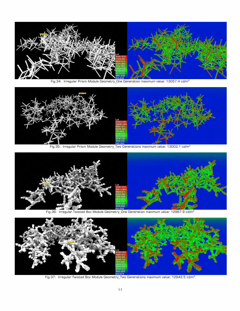
Fig.34: Irregular Prism Module Geometry_One Generation maximum value: 13057.4 cd/m
Fig.35: Irregular Prism Module Geometry_Two Generations maximum value: 13003.1 cd/m
2
Fig.36: Irregular Twisted Box Module Geometry_One Generation maximum value: 12967.9 cd/m
2
Fig.37: Irregular Twisted Box Module Geometry_Two Generations maximum value: 12943.5 cd/m
2
2

12
Fig.38: All Prism Modules Geometry maximum value: 18271.3 cd/m
Fig.39: All Twisted Box Modules Geometry maximum value: 12945.0 cd/m
2
2
The solar access test shows that the Irregular Prism One Generation model (Fig.28) performs very well in terms of solar insulation, reaching very low solar access values. However the pockets where the insulation is high are not really practicable because they are very small. This model also reaches quite homogeneous low solar access peaks. The Irregular Prism Two Generations model (Fig.29) does not achieve very low solar access values but it has a quite uniform distribution of insulation and average values. Very few low peaks are detected for this kind of geometry and the difference between them and the average is quite significant. The Irregular Twisted Box One Generation model (Fig.30) achieves the lowest solar access values distributed in a concentrated area. It also shows a medium-low range of average values surrounding the structure. It has very significant low peaks and there is a remarkable difference between them and the average values. The Irregular Twisted Box Two Generations model (Fig.31) performs really low values and shows a very well distributed insulation pattern, which makes it the best solution for solar insulation. It is also very important that there is an important area very well isolated relatively far away from the structure. It reaches low peaks and they are equally distributed along the structure.
Both the All Prism model (Fig.32) and the All Twisted Box model (Fig.33) perform mixed characteristics of the one and two generation prism and twisted box modules respectively. The curious aspect of it is that they achieve quite low punctual peaks distributed with certain order in a general pattern that shows a homogeneous average of values. Regarding the lighting analysis the maximum values the different populations show are slightly the same (they oscillate between 12943.5 cd/m2 and 1357.4 cd/m2) except for the case of the All Prism model (18271.3 cd/m2
) (Fig.38). The higher values are obviously located in the areas that have more solar access, which usually are the ones close to the perimeter of the structure. There the modules do not have other ones blocking light. In any case, there is a difference between the behavior of the prism geometries and the twisted box ones. In the first case, there are more areas with higher lighting values in the two generation model (Fig.35), whereas in the second one, that happens in the one generation model (Fig.36). Moreover the All Prism model (Fig.38) has more surfaces with higher lighting values than the All Twisted Box model (Fig.39).

13
Comparing the way different geometries gather together and their density, porosity, and friction features, we can conclude that the Irregular Prism One Generation model (Fig.19) reaches a high level of density and friction, and medium porosity standards (Tab.8). However a lot of modules are needed to achieve these properties. Otherwise it shows the lowest density and porosity values (Tab.9). The Irregular Prism Two Generations model (Fig.21) is the most porous and it achieves medium density and friction values (Tab.8-9). If the outcome is not made of many modules, the density is quite high and the friction reaches regular levels (Tab.9). The Irregular Twisted Box One Generation model (Fig.24) is the densest and the one that has more friction between elements, but only if an important amount of modules gather together (Tab.8). If this is not the case, the friction still keeps high values but the density decreases considerably (Tab.9). The Irregular Twisted Box Two Generations model (Fig.26)
has medium average density and porosity values and high friction values (Tab.8). However when taking into account the number of elements, it is the densest and the one that has more friction while its porosity is also quite high (Tab.9).
Models Density Porosity Friction
Fig.19 10.14 28.78 54.14
Fig.21 6.89 52.34 34.21
Fig.24 15.35 39.95 69.34
Fig.26 8.65 42.17 57.45
Tab.8: Density-Porosity-Friction in Model
Models
s
Density Porosity Friction
Fig.19 0.04 0.13 0.24
Fig.21 0.36 2.75 1.80
Fig.24 0.18 0.80 0.46
Fig.26 0.51 2.48 3.38
Tab.9: Density-Porosity-Friction in Models divided by the number of modules
To estimate the density of each model, the volume of an offset solid mass is calculated and then divided by the sum of all the volumes of every single module that conform the whole geometry. The porosity can be estimated calculating the volume of pockets or empty spaces in between the structural element. Finally, the friction calculation is based on the sum of the amount of the common surface that the modules share when they are in contact. All of these values can be divided by the
number of modules to get a result that does not depend on the amount of modules that are aggregated.
These conclusions draw a body of feedback that can be used to in-form different outcomes depending on design needs. Porosity, density, friction, solar access and lighting are determined by the geometry and morphology of the modules used. Hence it is up to the designer to manipulate the module and the way it is aggregated to get light or heavy structures able to insulate more or less, or to let light go through them or not, to design usable or inhabitable outcomes.
Fig.40: Irregular Prism One and Two Generations 3D printed modules
Fig.41: Irregular Prism One and Two Generations 3D printed model
14
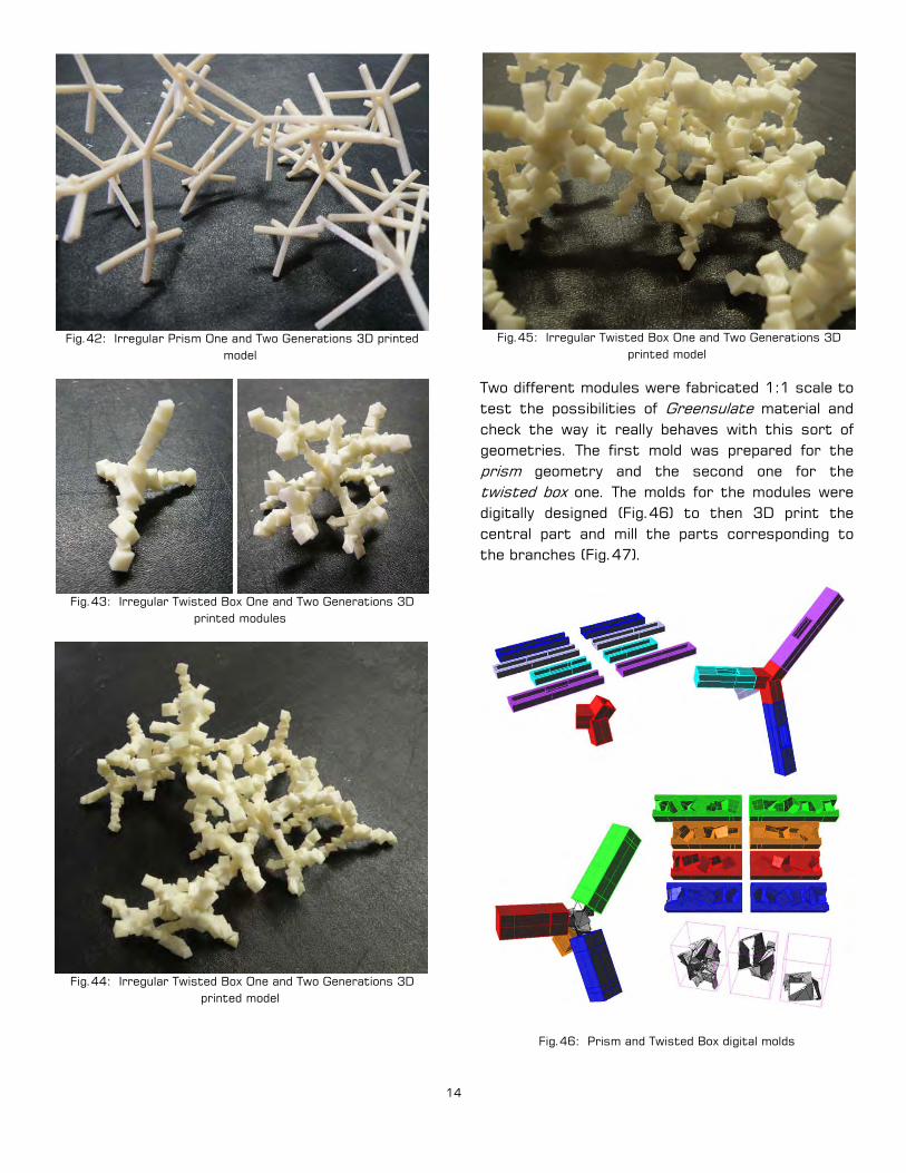
Fig.42: Irregular Prism One and Two Generations 3D printed model
Fig.43: Irregular Twisted Box One and Two Generations 3D printed modules
Fig.44: Irregular Twisted Box One and Two Generations 3D printed model
Fig.45: Irregular Twisted Box One and Two Generations 3D printed model
Two different modules were fabricated 1:1 scale to test the possibilities of Greensulate material and check the way it really behaves with this sort of geometries. The first mold was prepared for the prism geometry and the second one for the twisted box one. The molds for the modules were digitally designed (Fig.46) to then 3D print the central part and mill the parts corresponding to the branches (Fig.47).
Fig.46: Prism and Twisted Box digital molds
15
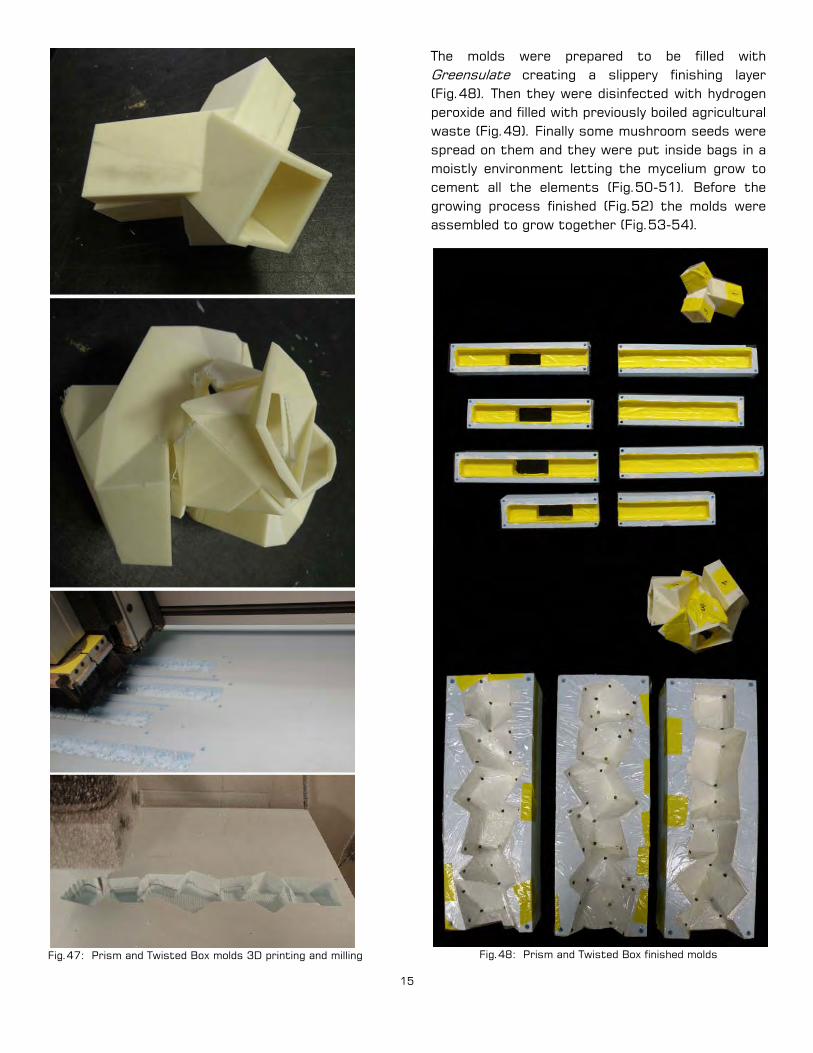
Fig.47: Prism and Twisted Box molds 3D printing and milling
The molds were prepared to be filled with Greensulate creating a slippery finishing layer (Fig.48). Then they were disinfected with hydrogen peroxide and filled with previously boiled agricultural waste (Fig.49). Finally some mushroom seeds were spread on them and they were put inside bags in a moistly environment letting the mycelium grow to cement all the elements (Fig.50-51). Before the growing process finished (Fig.52) the molds were assembled to grow together (Fig.53-54).
Fig.48: Prism and Twisted Box finished molds

16
Fig.49: Prism and Twisted Box molds filling process
Fig.50: Prism and Twisted Box central piece mold filled Fig.51: Prism and Twisted Box branches molds filled

17
Fig.52: Prism and Twisted Box molds growing
Fig.53: Prism and Twisted Box finished molds
Fig.54: Prism and Twisted Box molds assembled
The whole growing process took two weeks and finally the molds were removed and the outcome dried (Fig.55-58).

18
Fig.55: Prism mold outcome
Fig.56: Twisted Box mold outcome

19
Fig.57: Prism mold outcome details
Fig.58: Twisted Box mold outcome details
The modules came out very well but it would have worked better using plastic molds or slippery ones not to treat the surface before filling them. The outcome is resistant enough but the strength can be improved placing branches inside the molds before growing the material (Fig.59).
Fig.59: Branches used to improve structural features
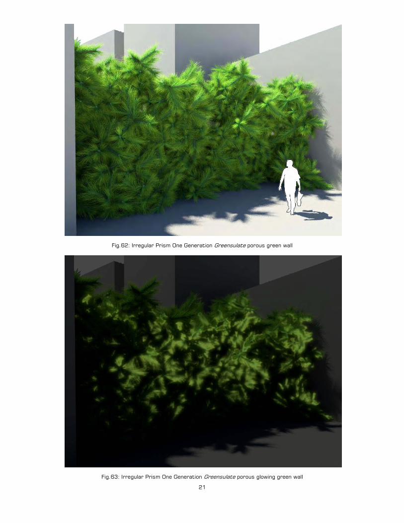
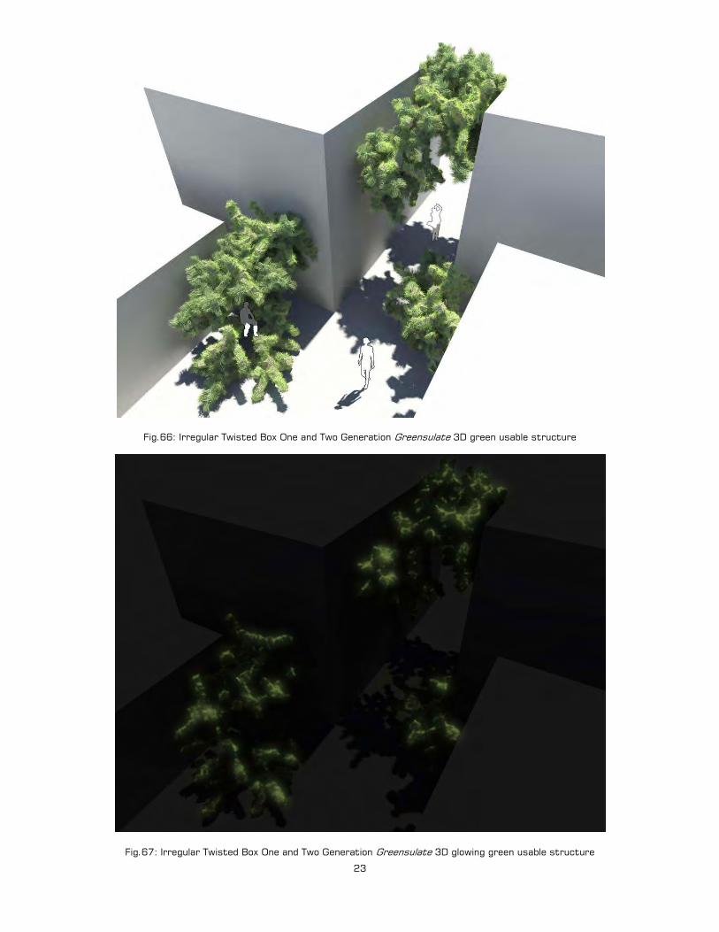
These kinds of geometries combined with the living intelligence of mycelium produce a usable structure that can be used to redefine pre-existing spaces in terms of lighting, insulation and solar access (Fig.58). It works indoors but also outdoors. In the second case the whole structure will not have a very long lasting life unless it is protected. These structures can work as public furniture pieces, devices to divide spaces, or supports for 3D-vertical gardens since grass and plants can grow on them (Fig.60-67). If the plants growing on them are genetically manipulated to glow or natural glowing mushrooms are used to produce the material, the structure will emit certain amount of light in the dark (Fig.63 and 67).

20
Fig.60: Irregular Prism One Generation Greensulate porous wall
Fig.61: Irregular Prism One Generation Greensulate porous green wall
21
Fig.62: Irregular Prism One Generation Greensulate porous green wall
Fig.63: Irregular Prism One Generation Greensulate porous glowing green wall

22
Fig.64: Irregular Twisted Box One and Two Generation Greensulate 3D usable structure
Fig.65: Irregular Twisted Box One and Two Generation Greensulate 3D green usable structure
23
Fig.66: Irregular Twisted Box One and Two Generation Greensulate 3D green usable structure
Fig.67: Irregular Twisted Box One and Two Generation Greensulate 3D glowing green usable structure

24
3. Grown Cultivated Habitat. Growing an architectural shelter is not a new idea. Manipulating vegetal elements like plants and trees for building purposes is a strategy that has been used since the beginning of times, either using them in a straight way or engineering the way they grow. Many approaches can be found in traditional architecture (Fig.68), arborsculpture (Fig.69), or more sophisticated contemporary approaches dealing with vegetal elements through digital tools (Fig.70-71).
Fig.68: Uros traditional reed houses
Fig.69: Basket-Tree Alex Erlandson
Fig.70: Habitary Topiary Noah Sherburn (2006)
Fig.71: Fab-Tree Hab Terreform1 (2006)
Anyway there is a good opportunity to rethink this issue considering a material like Greensulate, which performs very well in terms of insulation, and structural vegetal elements like branches. Since Greensulate is a biocomposite it will perfectly tolerate another organic component like branches. However the branches should be sprayed with hydrogen peroxide when filling the molds with agricultural waste and mushroom seeds not to contaminate the mixture, and to allow mycelium to grow properly. They can also be added when the mycelium has grown enough because the danger of contamination is almost zero then. Then we will get a biocomposite that performs structural features and insulating ones and that is 100% organic and disposable. Hence it would be easy to think about designing architectural shelters out of it.

25
Fig.72: Wall prototype mold
Fig.73: Wall prototype outcome
To fabricate a real sample of this biocomposite, another mold was filled with Greensulate and a structural mesh made of branches (Fig.72). Then an insulating and structural 100% organic wall prototype was achieved (Fig.73).
That would be the suitable biocomposite material to generate dwellings that could be placed in abandoned sites or rooftops to increase the density of cities without consuming blank ground. These spaces could host housing, studios, offices… (Fig.74-75). They could be used as an extension of a preexisting house or as a complement for it. They would allow people having a studio in the same building where they have their house but separated from it, or they could work as housing spaces placed in office buildings. They could be occupied by family members that might live apart but close to the family like teenagers or old people. This sort of inhabitable spaces could also be used for temporary inhabiting allowing people to live there for a while to then be dismantled. That would not be a problem since they are biodegradable.
This inhabiting system, which works as an organic prosthesis for the city, would minimize the number of displacements reducing pollution and fuel consumption. It would also avoid the waste of time produced by travelling inside the city.
Since Greensulate is made of organic materials it would allow the users to have cultivations or plants in their houses to grow food or just contribute to oxygen generation and air cleaning (Fig.77-78). Rooms like bathrooms, kitchens or storage spaces could be made of recycled plastic or rubber since they perform better for that purpose than Greensulate, even if it is improved with structural wooden branches (Fig.76). These boxes are conceived as independent spaces that can be aggregated or subtracted depending on user´s needs. However the rest of the house could be grown. These boxes could also storage water or be provided with devices to get clean energy to have a self-sufficient inhabitable space.
In addition, Greensulate could be used in public landscape surfaces hosting certain communal program or even for building insulating façades (Fig.75).

26
Fig.74: Grown Cultivated Habitat

27
Fig.75: Grown Cultivated public landscape and façade
Fig.76: Grown Cultivated Habitat structure and materials

28
Fig.77: Grown Cultivated Habitat
Fig.78: Grown Cultivated Habitat