group 17 propeller shafts - fmc · pdf filegroup 17 propeller shafts general: this group...
TRANSCRIPT

Group 17 Propeller Shafts
GENERAL: This group contains information on the propeller
shafts from the transmission to the differential,
and the differential to the rear drive wheels.
It also includes the axle shafts in the driving
hub.
SPECIFICS: As applicable
...Axle Shaft
...Axle Shaft Bearings
...Propeller Shafts and Universal Joints
•FMC FMC CorporationMotor Coach Division333 Brokaw Road Box 664 Santa Clara California 95052

REPAIR PARTS LIST17 Propeller ShaftsGROUP
MODEL 2900R
SD-1062
Figure 17-1. Propeller Shafts.
•FMC FMC CorporationMotor Coach Division333 Brokaw Road Box 664 Santa Clara California 95052
PAGE 17-1
ISSUED.
REVISED C4. 9/76

REPAIR PARTS LISTGROUP.
MODEL.
17
2900R
FIGNO.
ITEMNO. PART NUMBER ITEM DESCRIPTION QTY PER UNIT
7-1
1011
12131415
16
17
510010551001045100011-R221
5100041-R001
5100041-R0025100041-R0035100041-R0045100105-R0015100040
5100040-R0015100040-R0025100041-R005
5100041-R006
5100041-R0075100041-R0085100040-R0035107657
5100570-065100448M250015100447-01
5100446-11
5101294
SHAFT ASSY, Transmission todifferential (MJ-2A-4854)YOKE, Propeller shaft at transmission (MJ-3975J)NUT, Propeller shaft yoke to parking brake
(CCMI-9419656) (See Group 10)YOKE W/SLINGER, Prop shaft to differential
(RSD-A3280-P-5918)NUT,Yoke to differential (RSD-1227-C-939)WASHER, Yoke nut (RSD-1229-Z-2392)SLINGER, Yoke (RSD-2847-H-346)SCREW, Prop shaft attaching (MJ-3786J)SHAFT ASSY, Differential to fear wheels
(MJ-2A-22125-1)YOKE, Propeller shaft to rear wheel (MJ-25951J)SCREW, Propeller shaft to wheel yoke (MJ-9380J)YOKE, Propeller shaft to differential (MJ-7924)
(RSD-3280-H-1854)NUT,Propeller shaft yoke to differential
(RSD-14 x 57)WASHER, Propeller shaft yoke (RSD-1229-P-1030)COTTER, Propeller shaft yoke nut (RSD-K2416)SCREW, Propeller shaft yoke (MJ-3562J)AXLE SHAFT, Rear wheel drive (supersedes 5100061
and 5107639)WASHER, Axle shaft to yokeNUT, Axle shaft to yoke (SP-20-74-11)PIN, Axle shaft nut cotterSEAL, Axle shaft rear (CR-24911)
BEARING SET, Axle shaft (TRB-LM603049)(supersedes 5100446-05,5100446-^08, & 5100446-06)
NOTE: Above set consists of cones,cups, and spacer
RING, Axle shaft bearing cup retaining
•FMC FMC CorporationMotor Coach Division333 Brokaw Road Sox 664 Santa Clara California 95052
ISSUED
REVISED C4, 9/76
PAGE 17-2
REPAIR PARTS LISTGROUP.
SD-1045
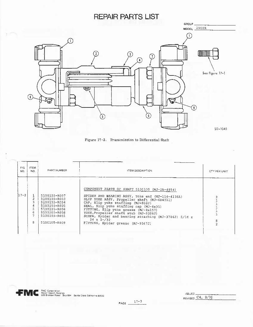
Figure 17-2. Transmission to Differential Shaft
FIGNO.
17-2
ITEMNO.
1234567
8
PART NUMBER
5100105-R0075100105-R0035100105-R0045100105-R0055100105-R0065100105-R0085100105-R001
5100105-R009
ITEM DESCRIPTION
COMPONENT PARTS OF SHAFT 5100105 (MJ-2A-4854)
SPIDER AND BEARING ASSY, Yoke end (MJ-114-4138A)SLIP YOKE ASSY, Propeller shaft (MJ-6D4011)CAP, Slip yoke stuffing (MJ-802J)SEAL, Slip yoke stuffing cap (MJ-6x35)FITTING, Slip yoke grease (MJ-8xl57)YOKE, Propeller shaft stub (MJ-5326J)SCREW, Spider and bearing attaching (MJ-3786J) 5/16 x
24 x 2-/32FITTING, Spider grease (MJ-9067J)
OTY PER UNIT
211111
82
-FMC FMC CorporationMotor Coach Division333 Brokaw Road Box 664 Santa Clara California 95052
ISSUED.
REVISED _C4, 9/76
PAGE17-3

REPAIR PARTS LISTGROUP 17 Propeller-Shafts
MODEL 2900R
WHEEL END
See figure 17-1
SD-1049
Figure 17-3. Differential to Rear Wheel Shaft
FIGNO.
17-3
ITEMNO.
12345678910
RVDPART NUMBER
5100040-R0045100040-R0055100040-R0065100040-R0075100105-R0095100040-R0035100040-R0085100040-R0095100040-R0105100105-R006
ITEM DESCRIPTION
COMPONENT PARTS OF SHAFT 5100040 (MJ-2A-22125-1)SPIDER AND BEARING ASSY, Stub yoke end (MJ-114-7205A)YOKE, Propeller shaft stub (MJ-26040J)YOKE, Propeller shaft slip (MJ-6D7004)SPIDER AND BEARING ASSY, Slip yoke end (MJ-114-7207A)FITTING, Spider grease (MJ-9067J)SCREW, Yoke to spider (MJ-3562J)CAP, Slip yoke (MJ-949J)WASHER, Slip yoke retainer (MJ-950J)WASHER, Slip yoke felt (MJ-6xlll)FITTING, Slip yoke grease (MJ-8X157)
QTYPER UNIT
22224162422
•FMCFMC CorporationMotor Coach Division333 Brokaw Road Box 664 Santa Clara California 95052
PAGE 17-4
ISSUED-4/73
REVISED ?4' V76

Group T-17
GROUP T-17
PROPELLER SHAFTSv
TABLE OF CONTENTS
PARAGRAPH PAGE
17-1 DESCRIPTION ' (T) 17-2
a. General (T) 17-2b. Transmission-to-Differential Propeller Shaft (T) 17-2c. Differential-to-Axle Propeller Shaft (T) 17-2d. Rear Wheel Axle Shafts (T) 17-2
17-2 TROUBLESHOOTING (T) 17-2
17-3 REMOVAL/INSTALLATION ;(T) 17-2
a. General (T) 17-2b. Transmission-to-Differential Propeller Shaft
Removal (T) 17-2c. Transmission-to-Differential Propeller Shaft
Installation (T) 17-2d. Differential-to-Axle Propeller Shaft Removal (T) 17-4e. Differential-to-Axle Propeller Shaft
Installation (T) 17-4f. Rear Axle Shaft Removal (T) 17-5g. Rear Axle Shaft Installation (T) 17-5
17-4 INSPECTION AND CLEANING (T) 17-6
a. General (T) 17-6b. Propeller Shaft Inspection (T) 17-6c. Cleaning (T) 17-6
17-5 GENERAL INFORMATION (T) 17-7
a. General (T) 17-7b. Torque Requirements (T) 17-7c. Lubrication of Propeller Shaft Spider/Bearings
and Slip and Stub Yoke Splines (T) 17-7d. Replacing Axle Shaft Matched-Set Bearing Cones (T) 17-7
Hot LaneParts Orders
(408) 779-3171
RECREATIONAL VEHICLE SERVICES INCRR2 Ml40 Monterey Rd.Morgan Hill, CA. 95037. T1</
408-779-3173

-
'

-
-RECREATIONAL VEHICLE SERVICES IN<TRR2 M140 Monterey Rd.Morgan Hill, CA. 95037
408-779-31Z328 2.9
DIFFERENTIAL (REF)
-v
LEGEND
1. BOLT (4)2. YOKE (INPUT)3. NUT4. LUBE FITTING*5. SHAFT ASSEMBLY
(TRANSMISSION-TO-DIFFERENTIAL)
6. SPIDER AND BEARING ASSY7. YOKE (STUB)8. YOKE (SLIP)9. BOLT (WITH LOCKWASHER) (4)
10. LUBE FITTING11. SPIDER AND BEARING ASSY12. COUPLING13. LUBE FITTING*14. NUT (4)
NOTE: ITEMS 15 THRU 29 REFLECTTHE LEFT SHAFT ASSEMBLYONLY, THE RIGHT SHAFT(NOT SHOWN) CONTAINSTHE SAME COMPONENTS.
15. SHAFT ASSEMBLY (DIFFERENTIAL-TO-REAR WHEEL SHAFT)
16. YOKE (OUTPUT)17. NUT18. BOLT (4)19. BOLT (4)20. YOKE21. COTTER PIN (FOR NUT 29)22. CONE WITH BEARINGS (2)23. SPACER (BETWEEN CONES)24. AXLE SHAFT25. CUP (BEARING) (2)26. RETAINING RING27. GREASE SEAL28. WASHER29. NUT
*DO NOT USE A HIGHPRESSURE GREASE GUNON THESE FITTINGS.
DRIVEFLANGE (REF)
PARKINGBRAKE
DRUM (REF)
TRANSMISSION (REF)
Hot Line
779-8173Figure 17-1. Propi'ller Shnlls
T17-2


Group T-'-!7
GROUP 17
PROPKl.LER SHAFT
17-1. DESCRIPTION
-L- fieneral (iig. 17-1). The coach drive linesystem contains three propeller shait assc-nibl:esand axle shafts. Engine torque ir» transmitted fromthe transmission output shaft to the input yokeof the differential by a single propoller shaft as-sembly; two identical propeller shau.« transmitthe output torque from tho .inferential to the rearwheel axle shafts. This group provides serviceinstructions for the propeller shaft asseuiDlios,
wore
For service information on the rear,s us pens! or; system, rtfer to Group 6;for the differential, refer to Group 13.When applicable, other groups are refer-enced in the text. For information onpart numbers anci procurement of re-placement parts; refer to Group 17 inthe Repair Farts. Catalog.
b. Transmission-h)-Differential PropellerShaft. The major components of theTrn-iSiciSoion-to-differential propeller .shaft consist of spiderbearing assemblies, a spiiued slip yoke, and asulinud stub yoke. The spider/bearing on the aftend of the propeller shaft is the two-' lock typewith four mounting holes through which four bolts(with spring-lock washers) are inserted into theparking brake drum uf the trans mission outputshaft. The forward spider/bearing is tne four-wing type and contains threaded holes thrcv.gh whichfour attaching bolts hold the shaft to the differentialinput yoke.
NOTE
The bearings of each spider/bcariTig arelubricated via internal passages in thespider body which interconnect with aLOW PRESSURE TYPE GREASE FIT-TING. The meshed splines of the slipand stub yokes are lubricated by agrease fitting installed in the slip yokehousing.
JL: Pifferential-to-Axle PropeU.'r Shafts^ Theinboard spider/bearing of each differential-to-axlepropeller shaft is attached by four bolts to thedifferential output yokos. The outboard spicier/
bearings are attached to the yoke installed over thesplined inboard ends of the axle by four bolts.Spider/bearings and slip and stub yokes are lubri-cated as described above.
i!.: Kear Wheel Axle Shafts. The rear wheel axleshaft meshes at the inboard side with the yoke ofthe propeller shaft leading to the differential. Atthe outboard side the axle shaft, mesheu with therear wheel drive flange to turn the wheel. The in-board yoke is secured: tc the axle shaft with a nutand cotiier -pin. (refer to Group 8 for «• heels). Theaxle shaft rides within the spindle of the trailingarm and votates on a matc.hed set of bearings atthe inboard end. The matched set of bearings isretaine:' within the housing by a spacer and retain-ing rin^s. A press-fit grease seal fits in a grooveon the inboard side of the trailing arm spindle.When replacing axle shaft bearings it is essentialto use a matched set of bearings and a new spacer,retaining riugy, and inboard seal.
17-2. TROUBLESHOOTING
Instructions for troubleshooting the propeller shaftsare contained in table 17-1. Prior to trouble-shooting, make a preliminary visual inspection toassist in locating the problem.
17-3. REMOVAL/INSTALLATIQN
£: General (fig. 17-1). Step-by-step instruc-tions for replacement of the propeller shafts andcomjjonents are provided in this section. Replace-ment parts should be procured from those listedin Group 17 of the Parts Catalog,
b. Transrmssion-to-DLffereirtiial PropellerShaft RernqyaY. To remove the traiisaiission-to-diSerential propeller shaft, proceed as follows:
( 5 ) Remove four bolts and lockwashcrs at-taching the aft end of shaft spider/bearing to thecoupling on the parking brake drum; retain bolts.
(2) Support shaft assembly, and remove foiubolts inserting through the yoke on the differentialinto the forward spider/beariug; retain bolts.
(3) Lower and remove shaft assembly.
c. Transraifision-to-Dlfferentlal Propeller
BULLETIN 2917-20002 T17-3

Group T-17-
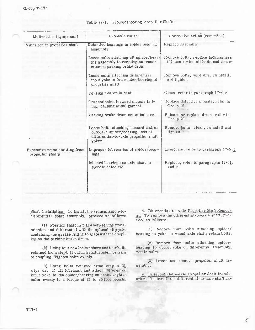
•Table 17-1. Troubleshooting Propeller Shafts
Malfunction (symptoms) Probable causes Corrective action (remedies)
Vibration in propeller shaft
Excessive noise emitting frompropeller shafts
Defective bearings in spider bearingassembly
Loose bolts attaching aft spider/bear-ing assembly to coupling on trans-mission parking brake drum
Loose bolts at taching d i f ferent ia linput yoke to fwd spider/bearing ofpropeller shaft
Foreign matter in shaft
Transmission forward mounts fail-ing, causing misalignment
Parking brake drum out of balance
Loose bolts attaching inboard and/oroutboard spider/bearing ends ofdifferential-to-axle propeller shaftyokes
Improper lubrication of spider/bear-ings
Inboard bearings on axle shaft inspindle defective
Replace assembly
Remove bolts, replace lockwashers(4) then re-install bolts and lighten
Remove bolls, wipe dry, reinstall,and tighten
Clean; refer to paragraph 17-4,£
Replace defective mounts; refer toGroup 16
Balance or replace drum; refer toGroup 10
Remove bolts, clean, reinstall andtighten
Lubricate; refer to paragraph 17-5,£
Replace; refer to paragraphs 17-3f_.and g_.
Shaft Installation. To install the transmission-to-differential shaft assembly, proceed as follows:
(1) Position shaft in place between the trans-mission and differential with the splined slip yokecontaining the grease fitting to mate with the coupl-ing on the parking brake drum.
(2) Using four new lockwashers and four boltsretained from stepb.(l), attach shaft spider/bearingto coupling. Tighten bolts evenly.
(3) Using bolts retained from step b.(2),wipe dry of all lubricant and attach differentialinput yoke to the spider/bearing on shaft. Tightenbolts evenly to a torque of 25 to 30 foot pounds.
- : ™
d. Differential-Jo-Axle Propeller Shaft Remov-al. To remove the differential-to-axle shaft, pro-ceed as follows:
(1) Remove four bolts attaching spider/bearing to yoke on wheel axle shaft; retain bolts.
(2) Remove four bolts attaching spider/bearing to output yoke on differential assembly;retain bolts.
(3) Lower and remove propeller shaft as-sembly.
e. Differential-to-Axle Propeller Shaft Insta.ll-ation. To install the differential-to-axle shaft as-
T17-4
c

Group T-17
sembly proceed as follows:
(1) Position shaft in place between the axleyoke and differential with the splined slip yokecontaining the grease fitting to mate with the yokeon the axle shaft end.
(2) Using four bolts retained from stepd.(l), wipe dry of all lubricant and attach outboardshaft spider/bearing to yoke on axle shaft. Tightenbolts evenly to a torque of 25,to 30 foot pounds.
(3) Using bolts retained from step d.(2),wipe dry of all lubricant and attach differentialoutput yoke to the inboard spider/bearing on shaft .Tighten bolts evenly to a torque of 25 to 30 footpounds.
t^ Rear Axle Shaft Removal. To remove rearaxle shaft, proceed as follows:
(1) Remove four bolts attaching propellershaft spider/bearing yoke on rear wheel axle shaftand lower end of propeller shaft to allow inboardmovement of axle shaft; retain bolts.
(2) Remove cotter pin, nut and washer frominboard end of axle shaft. Mark yoke potntion onshaft to aid in reinstallation, then remove splinedyoke; retain washer, nut and yoke.
(3) Remove wheel cover from outboard rearwheel.
(4) Remove hub cap.
(5) Remove eight nuts and lockwashers at-taching the drive flange to drive studs on hub,then remove drive flange; retain nuts and driveflange (if new lockwashers are available, discardold).
(6) Use bearing puller (with large jaws) andremove press-fit grease seal from inboard end ofaxle shaft.
NOTE
During following step, do not rotatepuller until the back of the bearing cupcan be inspected to determine at whatdegree the identification markings havebeen positioned. Note this position foruse during reinstallation procedures.This is important as cups do not rotateand consequently the load is concen-trated in a relatively small area. Byrotating the cups 90 degrees during rc-instillation, a new load zone is estab-lished and the life of the cup (and ben ringwhen reused) is prolonged.
(7) Use bearing puller (with large jaws) andremove inboard bearing cone and cup surroundingthe axle shaft from the I.D. of spindle. Retain cup(and bearing cone if it is to be reused).
(8) Remove bearing-cone spacer; retain.
(9) Use retaining pliers (internal type) andinsert into holes in the two lugs on the retainingring gapped ends. The retaining ring is seated ina groove and holds the inner bearing cone and cupin the spindle. Compress retaining ring until freeof groove edges, then pull out ring; retain ring.
NOTE
As shaft is removed from spindle duringfollowing step, do not rotate until theback of the bearing cup can be inspectedto determine at what degree the identi-fication markings have been positioned.Note tliis position for use during rein-stallation procedures. This is importantas cups do not rotate and consequentlythe load is concentrated in a relativelysmall area. By rotating the cups 90degrees during reinstallation in the spin-dle, a new load zone is established andthe life of the cup (and bearing whenreused) is prolonged.
(10) Install protector on splines of outboardend of axle shaft. Use load or soft-headed hammerto tap shaft and force shaft, bearing cone, andpress-fit bearing cup out the inboard side of thetrailing arm spindle. Check cup positioning perabove NOTE. Lower and remove shaft, then removebearing cone and cup from O.D. of shaft. Retainshaft and cup (and bearing cone if it is to be reused).
(11) Remove grease from I.D. of spindlecavity and flush or wipe clean, making sure noforeign material remains in internal groove forthe retaining ring.
(12) Clean and repack matched bearing coneset, as required, refer to paragraph 17-5,c_.
g. Rear Axle Shaft Installation. To install rearaxle shaft, bearings, grease seal and yoke, proceedas follows:
(1) Lubricate spindle outboard bearing cavityarea I.D. with sufficient pi-ease (NLG1 Grade 2)to form a dam around the bearing mount areas tohold the. grease in pl.iee and insert axle shaft.
T17-5
GroapT-17
into I.D. of spindle so that spanes on outboard endsof shaft just clear the outboard «nd -01 spindle.
The two bearing cones for th«3 axle shaftare a matched set and if one is defectiveit is necessary to replac e both to ensureequal load distribution and -wear.
(2) Insert repacked bearing cone in cup andposition assembly to enter the I.D. of spindle 00degrees clockwise from its previous position asnoted in step f.(9), and with back face of cupinboard and bearing cone protruding out of cuptoward outboard end of shaft. Install repackedoutboard bearing cone and cup assembly by usingsuitable device to press assembly in position a-round the axle shaft in I.D. of the spindle.
(3) Use retaining ring pliers (internal type)and insert into holes in the two lugs o/i the re-taining ring gapped ends. Compress ring and in-sert over axle shaft and seat in the grooves inspindle I.D. just inboard of previously installedbearing cup.
(4) Install bearing cone spacer over shaftand insert into I.D. of spindle to contact face ofthe bearing cup.
(5) Insert repacked bearing cone in cup andposition assembly to enter the I.D. of spindle 90degrees clockwise from its previous position asnoted in preceding step f.(6), and with back faceof cup outboard and bearing cone protruding out ofcup toward inboard end of shaft. Then h-stall re-packed inboard bearing cone and cup by usingsuitable device to press cup and bearing assemblyin position around the axle shaft in spindle I.D.
(0) Pack inboard bearing cavity areas ex-tending inboard to grease seal groove in spindlewith grease (NLG1 Grade 2).
(7) Install new grease seal in inboard groovein spindle; seal may be driven ;in with a woodenblock tapped with a hammer or with an arborpress.
(8) Lightly lubricate -ttireads of drive flangemounting studs with tlireadLube.
(9) Install new O-ring in drive flange groove.
(10) Secure drive flange with eight washersand nuts; tighten nuts 39 to 43 foot pounds.
(11) Install hub cap in flange over end of out-board end of axle shaft.
(12) Install wheel cover.
(13) Install yoke on inboardsplinedendof axleshaft in position marked during removal, usingcare not to damage grease seal.
(14) Secure yoke^on axle shaft end with wasiierand nut. Torque nut to ̂ f foot pounds to seat bear-ings, ther back nut off 1/6 to 1/4 turn and installnew cotter pin.
(15) Align propeller shaft spider/bearing withyoke mount holes and attach witti four bolts (wipebolts dry of all lubricant) retained daring removal;torque bolts 25 to 30 foot pounds.
17-4. INSPECTION AND CLEANING
a_. General. The following procedures provideinformation necessary for inspection and cleaningof the propeller shafts.
^i Propeller Shaft Inspection (fig. 17-1).
(1) With the engine shut down, parking brakeson, and the wheels securely blocked against move-ment, inspect the propeller shafts and yokes forevidence of loose parts, contamination, excessiveplay, cracks, and damaged parts. Clean foreignmatter from parts with water and/or compressedair. as necessary. Replace damaged parts.
(2) Check all fasteners for secure mountingusing torque wrench, where applicable.
c. Cleaning. Thorough cleaning of the propellershaft exterior is an essential prelude to any closeinspection, in order that the existence and extentof material defects can be determined. It is recom-mended that the propeller shafts be cleaned period-ically to remove mud, dirt, undercoating or rustproofing accumulations which could cause vibration.Conventional drive-in, do-it-yourself, high pres-sure spray type washing will normally providesufficient cleaning. Care must be taken not to directspray pressure on grease seals. Direct the sprayfrom under the coach up into liard-to-see spots.Do not spray areas other than the propeller shafts,differential, or transmission. Spraying witix a soapsolution should be followed by a water rinse to re-move all traces of the solution. Followingwashirtg,apply lubricant to gr«?:\se fittings (use low pres-sure grease gun), if needed; refer to paragraph 17-
.5,c.
T17-6BULLETIN 2917-20002

, i:,._ ,-.-..
Group T-17
17-5. GENERAL INFORMATION
a. General. This section contains general in-formation related to data contained in the previousparagraphs.
b. Torque Requirements. Torque requirementsfor the propeller shafts are specified Li table 17-2.
_£. Lubrication of Propeller Shaft Spider/Bear-ings and Slip and Stub Splines. The bearings "ofeach spider/bearing are supplied lubricant viainternal passages in the spider body which inter-connect with a low pressure type grease fitting.The meshed splines of the slip and .stub yokes aresupplied lubricant from a grease fitting installedin the slip yoke housing. Lubricate with grease,NLG1 Grade 2. Apply grease to fittings with a lowpressure hand-type grease gun or a high pressuregun with a low pressure adapter only.
Do not use a high pressure grease gunon spider/bearing grease fittings, asit will rupture the cork seals.
; Axle Shaft Matched-Set BearingCones. To repack axle shaft bearing cones, pro~ceed as follows:
(1) Using Croft T310 bearing packer, placesmall end of bearing cone to press down on toolcup.
(2) Position packer handle cone on top ofbearing.
(3) Press down on. handle to forca lubethrough bearing recesses.
NOTE
With bearing cone.in packer, apply onlymoderate pressure on handle to ensureeven grease flow into bearing recesses.
(4) Lift handle and slide bearing out overedge cf bearing cup.
j ,.-*-. ?~
(5) Repeat steps (1) through (4) for oppositebearing cone.
$000i
Table 17-2. Torque Requirernents
Part secured
Yoke to fwd spider/bearingon transmission-to-differ-entia! propeller shaft
Differential and axle yokesto spider/bearings ondifferential-to-axle pro-peller shaf t s
Drive flange to drive jstuds on hub
Yoke to spliued inboardend of axle shaft
Attaching part(s)
Bolts (4), dry, non-lubricated
Bolts (4 on each end) dry,non-lubricated
Nuts (4) and washers
Nut and washer
Torque(foot-pounds)
25 to 30
25 to 30
39 to 43
Ttcfer to paragraphg. , step (14)
17-3,
BULLETIN P917-20002T17-7